EP4556244A1 - Storage bag and printing apparatus - Google Patents
Storage bag and printing apparatus Download PDFInfo
- Publication number
- EP4556244A1 EP4556244A1 EP24213286.8A EP24213286A EP4556244A1 EP 4556244 A1 EP4556244 A1 EP 4556244A1 EP 24213286 A EP24213286 A EP 24213286A EP 4556244 A1 EP4556244 A1 EP 4556244A1
- Authority
- EP
- European Patent Office
- Prior art keywords
- surface portion
- convex
- storage bag
- coupling
- convex portion
- Prior art date
- Legal status (The legal status is an assumption and is not a legal conclusion. Google has not performed a legal analysis and makes no representation as to the accuracy of the status listed.)
- Pending
Links
Images



Classifications
-
- B—PERFORMING OPERATIONS; TRANSPORTING
- B41—PRINTING; LINING MACHINES; TYPEWRITERS; STAMPS
- B41J—TYPEWRITERS; SELECTIVE PRINTING MECHANISMS, i.e. MECHANISMS PRINTING OTHERWISE THAN FROM A FORME; CORRECTION OF TYPOGRAPHICAL ERRORS
- B41J2/00—Typewriters or selective printing mechanisms characterised by the printing or marking process for which they are designed
- B41J2/005—Typewriters or selective printing mechanisms characterised by the printing or marking process for which they are designed characterised by bringing liquid or particles selectively into contact with a printing material
- B41J2/01—Ink jet
- B41J2/17—Ink jet characterised by ink handling
- B41J2/175—Ink supply systems ; Circuit parts therefor
-
- B—PERFORMING OPERATIONS; TRANSPORTING
- B41—PRINTING; LINING MACHINES; TYPEWRITERS; STAMPS
- B41J—TYPEWRITERS; SELECTIVE PRINTING MECHANISMS, i.e. MECHANISMS PRINTING OTHERWISE THAN FROM A FORME; CORRECTION OF TYPOGRAPHICAL ERRORS
- B41J2/00—Typewriters or selective printing mechanisms characterised by the printing or marking process for which they are designed
- B41J2/005—Typewriters or selective printing mechanisms characterised by the printing or marking process for which they are designed characterised by bringing liquid or particles selectively into contact with a printing material
- B41J2/01—Ink jet
- B41J2/17—Ink jet characterised by ink handling
- B41J2/175—Ink supply systems ; Circuit parts therefor
- B41J2/17503—Ink cartridges
- B41J2/17513—Inner structure
-
- B—PERFORMING OPERATIONS; TRANSPORTING
- B41—PRINTING; LINING MACHINES; TYPEWRITERS; STAMPS
- B41J—TYPEWRITERS; SELECTIVE PRINTING MECHANISMS, i.e. MECHANISMS PRINTING OTHERWISE THAN FROM A FORME; CORRECTION OF TYPOGRAPHICAL ERRORS
- B41J2/00—Typewriters or selective printing mechanisms characterised by the printing or marking process for which they are designed
- B41J2/005—Typewriters or selective printing mechanisms characterised by the printing or marking process for which they are designed characterised by bringing liquid or particles selectively into contact with a printing material
- B41J2/01—Ink jet
-
- B—PERFORMING OPERATIONS; TRANSPORTING
- B41—PRINTING; LINING MACHINES; TYPEWRITERS; STAMPS
- B41J—TYPEWRITERS; SELECTIVE PRINTING MECHANISMS, i.e. MECHANISMS PRINTING OTHERWISE THAN FROM A FORME; CORRECTION OF TYPOGRAPHICAL ERRORS
- B41J2/00—Typewriters or selective printing mechanisms characterised by the printing or marking process for which they are designed
- B41J2/005—Typewriters or selective printing mechanisms characterised by the printing or marking process for which they are designed characterised by bringing liquid or particles selectively into contact with a printing material
- B41J2/01—Ink jet
- B41J2/17—Ink jet characterised by ink handling
- B41J2/175—Ink supply systems ; Circuit parts therefor
- B41J2/17503—Ink cartridges
- B41J2/17553—Outer structure
-
- B—PERFORMING OPERATIONS; TRANSPORTING
- B41—PRINTING; LINING MACHINES; TYPEWRITERS; STAMPS
- B41J—TYPEWRITERS; SELECTIVE PRINTING MECHANISMS, i.e. MECHANISMS PRINTING OTHERWISE THAN FROM A FORME; CORRECTION OF TYPOGRAPHICAL ERRORS
- B41J2/00—Typewriters or selective printing mechanisms characterised by the printing or marking process for which they are designed
- B41J2/005—Typewriters or selective printing mechanisms characterised by the printing or marking process for which they are designed characterised by bringing liquid or particles selectively into contact with a printing material
- B41J2/01—Ink jet
- B41J2/17—Ink jet characterised by ink handling
- B41J2/175—Ink supply systems ; Circuit parts therefor
- B41J2/17503—Ink cartridges
- B41J2/17559—Cartridge manufacturing
-
- B—PERFORMING OPERATIONS; TRANSPORTING
- B41—PRINTING; LINING MACHINES; TYPEWRITERS; STAMPS
- B41J—TYPEWRITERS; SELECTIVE PRINTING MECHANISMS, i.e. MECHANISMS PRINTING OTHERWISE THAN FROM A FORME; CORRECTION OF TYPOGRAPHICAL ERRORS
- B41J2/00—Typewriters or selective printing mechanisms characterised by the printing or marking process for which they are designed
- B41J2/005—Typewriters or selective printing mechanisms characterised by the printing or marking process for which they are designed characterised by bringing liquid or particles selectively into contact with a printing material
- B41J2/01—Ink jet
- B41J2/17—Ink jet characterised by ink handling
- B41J2/175—Ink supply systems ; Circuit parts therefor
- B41J2/17503—Ink cartridges
- B41J2/17513—Inner structure
- B41J2002/17516—Inner structure comprising a collapsible ink holder, e.g. a flexible bag
Definitions
- the present disclosure relates to a storage bag and a printing apparatus.
- Japanese Patent Laid-Open No. 2012-16825 has disclosed an ink pack (storage bag) comprising an upper-side gusset portion and a lower-side gusset portion.
- the rigidity of the lower-side gusset portion is greater than the rigidity of the upper-side portion, and therefore, while ink is being used, the lower-side gusset portion is folded up after the upper-side gusset portion is folded up.
- the configuration such as this while ink is being used, after the upper side of the ink pack is crushed, the lower side of the ink pack is crushed gradually, and therefore, the used-up property of ink is implemented.
- An object of the present disclosure is to provide a storage bag capable of suppressing the occurrence of a vertical fold at the gusset portion and improving the use-up property of ink.
- the present invention in its first aspect provides a storage bag (200) as specified in claims 1 to 16.
- the present invention in its second aspect provides a printing apparatus (100) as specified in claim 17.
- the carriage 104 reciprocates along the two guide rails 105.
- the printing medium 101 that receives liquid ejected from a liquid ejection unit (not shown schematically) of the print head 103 is conveyed by the conveyance roller 102 in the conveyance direction facing a liquid ejection surface of the print head 103 and perpendicular to the movement direction of the carriage 104.
- the liquid supply unit 106 comprises a pump mechanism (not shown schematically). It is possible for the pump mechanism to suck in liquid from the storage container 109 and send the liquid to the print head 103.
- FIG. 2 is an exploded perspective diagram of the storage bag 200 in the present embodiment.
- the storage bag 200 comprises a bag body 201 with flexibility capable of hermetically storing liquid and the discharge port 202 discharging liquid to the outside from the inside of the bag body 201.
- the discharge port 202 is manufactured by injection molding.
- the bag body 201 includes a top surface film 204 located on the top surface side and an undersurface film 205 opposite to the top surface film 204 and located on the undersurface side in a posture in which the bag body 201 is used.
- the bag body 201 includes a left surface film 206 connecting the end portion of the top surface film 204 and the end portion of the undersurface film 205.
- the storage bag 200 includes a right surface film 207 opposite to the left surface film 206 and connecting the end portion of the top surface film 204 and the end portion of the undersurface film 205.
- the top surface film 204, the left surface film 206, the undersurface film 205, and the right surface film 207 include a material suppressing leakage of liquid stored internally and likely to be coupled (in the present embodiment, likely to be thermally welded).
- the top surface film 204, the left surface film 206, the undersurface film 205, and the right surface film 207 may be coupled by an adhesive agent.
- each of the top surface film 204, the left surface film 206, the undersurface film 205, and the right surface film 207 there are polyethylene, polypropylene and the like.
- a multilayer film including a plurality of materials such as aluminum, PET (polyethylene terephthalate), nylon and the like.
- the top surface film 204 and the undersurface film 205 are coupled via the double-folded left surface film 206 and the double-folded right surface film 207.
- the left and right portions of the top surface film 204 and the undersurface film 205 are coupled via a first end portion 209 of a first folding line 208 in the left surface film 206 and a second end portion 211 of a second folding line 210 in the right surface film 207.
- the center portions of the top surface film 204 and the undersurface film 205 are coupled directly without the intervention of another film.
- the top surface film 204 and the undersurface film 205 are coupled in a state where the double-folded left surface film 206, the double-folded right surface film 207, and part of the discharge port 202 are sandwiched.
- the left and right portions of the top surface film 204 and the undersurface film 205 are coupled via a third end portion 212 of the first folding line 208 and a fourth end portion 213 of the second folding line 210.
- the center portions of the top surface film 204 and the undersurface film 205 are coupled directly in a state where part of the discharge port 202 is sandwiched.
- the hermetically sealed storage bag 200 is formed as described above.
- the left surface film 206 and the right surface film 207 function as a gusset portion.
- FIG. 3 is a diagram explaining the occurrence of a vertical fold 300.
- the storage bag 200 is shown in the posture in which the storage bag 200 is used (that is, posture in which the storage bag 200 is mounted on the liquid supply unit 106).
- liquid not less than 50% and not more than 80% of the maximum amount that can be stored is stored in the storage bag 200 before the start of its use (that is, in the initial state).
- the larger the amount of the remaining liquid in the storage bag 200 the more the storage bag 200 swells out.
- the more the storage bag 200 swells out the larger the angle formed by the upper side and the lower side with the first folding line 208 as a boundary becomes in the left surface film 206.
- the angle formed by the upper side and the lower side with the second folding line 210 (not shown schematically in FIG. 3 ) as a boundary becomes large .
- the liquid moves inside the storage bag 200 and the left surface film 206 and the right surface film 207 spread.
- the discharge port 202 is directed upward in the direction of gravity by a user.
- the liquid moves to a position distant from the discharge port 202 and accumulates at the position.
- the posture of the storage bag 200 changes as described above, the left surface film 206 and the right surface film 207 are pushed and spread from the inside of the bag body 201 toward the outside.
- the left surface film 206 and the right surface film 207 function as a gusset portion and are capable of increasing the capacity of the bag body 201.
- each of one end portion in the top surface film 204 and one end portion in the undersurface film 205 is coupled via each of the first end portion 209 and the second end portion 211.
- each of the other end portion in the top surface film 204 and the other end portion in the undersurface film 205 is coupled via each of the third end portion 212 and the fourth end portion 213. Consequently, the range is limited in which the left surface film 206 and the right surface film 207 can spread as a gusset portion.
- the vertical fold 300 substantially perpendicular to the first folding line 208 becomes more likely to occur.
- the vertical fold 300 substantially perpendicular to the second folding line 210 becomes more likely to occur.
- the vertical fold 300 serves as a resistance to the folding and blocks smooth shrinkage of the storage bag 200.
- each of the left surface film 206 and the right surface film 207 is folded up along each of the first folding line 208 and the second folding line 210 and the capacity of the storage bag 200 is reduced.
- the folding of the left surface film 206 and the right surface film 207 is blocked and it becomes difficult to use up the liquid.
- the shape of the coupling portion of each film is allowed to have a feature.
- the bag body 201 comprises the coupling portion 400 at which the top surface film 204, the left surface film 206, the right surface film 207, and the undersurface film 205 are coupled.
- the top surface film 204, the left surface film 206, the right surface film 207, and the undersurface film 205 are thermally welded at the coupling portion 400. That is, in the present embodiment, the coupling portion 400 is a welding area.
- the coupling portion 400 includes a first area 401 coupling the end portion of the left surface film 206 and the end portion of the top surface film 204 along the entire area in a first direction (Y-direction) and a first convex portion 402 configured to protrude toward the inside of the top surface film 204 from the first area 401.
- the coupling portion 400 includes a second area 403 coupling the end portion of the left surface film 206 and the end portion of the undersurface film 205 along the entire area in the first direction (Y-direction) and a second convex portion 404 configured to protrude toward the inside of the undersurface film 205 from the second area 403.
- the coupling portion 400 includes a third area 405 coupling the end portion of the right surface film 207 and the end portion of the top surface film 204 along the entire area in the first direction (Y-direction) and a third convex portion 406 configured to protrude toward the inside of the top surface film 204 from the third area 405.
- the coupling portion 400 includes a fourth area 407 coupling the end portion of the right surface film 207 and the end portion of the undersurface film 205 along the entire area in the first direction (Y-direction) and a fourth convex portion 408 configured to protrude toward the inside of the undersurface film 205 from the fourth area 407.
- the first direction (Y-direction) is the direction from the bottom portion of the bag body 201 toward the discharge port 202.
- the first convex portion 402, the second convex portion 404, the third convex portion 406, and the fourth convex portion 408 it is made easy to suppress the occurrence of the vertical fold 300 (see FIG. 3 ) extending along the Z-direction. As long as it is possible to suppress the occurrence of the vertical fold 300 (see FIG. 3 ), the position at which the first convex portion 402, the second convex portion 404, the third convex portion 406, and the fourth convex portion 408 are provided may not be the same position in the Y-direction.
- a coupling tool (not shown schematically) coupling these four films while pressing them together is used.
- a welding tool (not shown schematically) welding the top surface film 204, the left surface film 206, the right surface film 207, and the undersurface film 205 while pressing them together is used.
- a welding tool (not shown schematically) welding the top surface film 204, the left surface film 206, the right surface film 207, and the undersurface film 205 while pressing them together is used.
- the welding tool by designing part of the pressing surface of the welding tool the same shape as that of the first convex portion 402, the second convex portion 404, the third convex portion 406, and the fourth convex portion 408, it is possible to thermally weld these four films together while providing these four convex portions.
- the welding method such as this, it is possible to form the shape of the coupling portion 400 without increasing the number of processes.
- FIG. 5 is a diagram explaining the coupling portion 400 in the present embodiment.
- the first convex portion 402 in the coupling portion 400 has a first width 501, which is the length in the first direction (Y-direction), and a first protrusion amount 502, which is the length in a second direction (X-direction).
- the second convex portion 404 (not shown schematically in FIG. 5 ) also has a second width (not shown schematically in FIG. 5 ), which is the length in the first direction (Y-direction), and a second protrusion amount 605 (see FIG. 6C ) protruding in the second direction (X-direction) from the second area 403.
- the third convex portion 406 has a third width 503, which is the length in the first direction (Y-direction), and a third protrusion amount 504 protruding along the second direction (X-direction) from the third area 405.
- the fourth convex portion 408 (not shown schematically in FIG. 5 ) also has a fourth width (not shown schematically in FIG. 5 ), which is the length in the first direction (Y-direction), and a fourth protrusion amount (not shown schematically in FIG. 5 ) protruding in the second direction (X-direction) from the fourth convex portion 408.
- the first width 501, the second width, the third width 503, and the fourth width are not less than about 5 mm and not more than about 30 mm.
- the first protrusion amount 502, the second protrusion amount, the third protrusion amount 504, and the fourth protrusion amount are not less than about 5 mm and not more than about 30 mm.
- each of a plurality of the first convex portions 402 it is preferable for each of a plurality of the first convex portions 402 to be provided within a range not less than about 10 mm and not more than about 70 mm from each of the fist end portion 209 and the third end portion 212 toward the inside of the first folding line 208.
- each of a plurality of the second convex portions 404 (not shown schematically in FIG. 5 ) to be provided within a range not less than about 10 mm and not more than about 70 mm from each of the fist end portion 209 and the third end portion 212 toward the inside of the first folding line 208.
- each of a plurality of the third convex portions 406 it is preferable for each of a plurality of the third convex portions 406 to be provided within a range not less than about 10 mm and not more than about 70 mm from each of the second end portion 211 and the fourth end portion 213 toward the inside of the second folding line 210.
- each of a plurality of the fourth convex portions 408 (not shown schematically in FIG. 5 ) to be provided within a range not less than about 10 mm and not more than about 70 mm from each of the second end portion 211 and the fourth end portion 213 toward the inside of the second folding line 210.
- the reason is that by providing the above-described plurality of the convex portions within the above-described range, it is possible to efficiently suppress the occurrence of the vertical fold 300. For example, in a case where the bottom portion (end portion on the side in the -Y-direction) of the storage bag 200 is directed downward in the direction of gravity, the liquid gathers downward.
- FIG. 6A is a plan diagram showing an area VI in FIG. 5 .
- the first protrusion amount 502 in the first convex portion 402 is about two thirds or less of the shortest distance from the first area 401 to the first folding line 208.
- FIG. 6B is a cross-sectional diagram along a VIB-VIB line in FIG. 6A .
- the solid-line portion in FIG. 6B shows the posture in which the storage bag 200 is used (posture in which the storage bag 200 is placed horizontally).
- the broken-line portion in FIG. 6B shows the posture, which is moved from the posture in which the storage bag 200 is place horizontally, and in which the discharge port 202 (not shown schematically in FIG. 6B ) is held upright so as to face upward.
- the bag body 201 has a second distance 602 from the top surface film 204 to the undersurface film 205.
- the second distance 602 is greater than the first distance 601.
- the bag body 201 has a second angle 612 formed by the upper side and the lower side of the left surface film 206 with the first folding line 208 as a boundary.
- the second angle 612 is larger than the first angle 611.
- the ink within the bag body 201 moves in the direction of gravity. Because of this, at the bottom portion of the storage bag 200, the left surface film 206 swells out in the direction in which the left surface film 206 opens against the first folding line 208.
- the left surface film 206 opening as described above the second distance 602 from the top surface film 204 to the undersurface film 205 becomes greater than the first distance 601 before the left surface film 206 opens.
- FIG. 6C is a cross-sectional diagram along a VIC-VIC line in FIG. 6A .
- the solid-line portion in FIG. 6C shows the state where the storage bag 200 is used (state where the storage bag 200 is placed horizontally).
- the broken-line portion in FIG. 6C shows the posture after the storage bag 200 is moved from the posture in which the storage bag 200 is placed horizontally and the discharge port 202 (not shown schematically in FIG. 6C ) is held upright so as to face upward.
- the amount of remaining liquid in each of the solid-line portion and the broken-line portion is the same as the amount of remaining liquid in each of the solid-line portion and the broken-line portion shown in FIG. 6B .
- the bag body 201 has a third distance 603 from the top surface film 204 to the undersurface film 205. However, the first convex portion 402 and the second convex portion 404 are provided, and therefore, the third distance 603 is smaller than the first distance 601 (see FIG. 6B ). In the posture in which the storage bag 200 is used, the bag body 201 has a third angle 613 formed by the upper side and the lower side of the left surface film 206 with the first folding line 208 as a boundary.
- the bag body 201 has a fourth distance 604 from the top surface film 204 to the undersurface film 205.
- the fourth distance 604 is greater than the third distance 603.
- the first convex portion 402 and the second convex portion 404 are provided, and therefore, the fourth distance 604 is smaller than the second distance 602 (see FIG. 6B ).
- the left surface film 206 opens and the bag body 201 has a fourth angle 614 formed by the upper side and the lower side of the left surface film 206 with the first folding line 208 as a boundary.
- the fourth angle 614 is larger than the third angle 613.
- the portion at which the first convex portion 402 and the second convex portion 404 are provided has a movable area in the ⁇ Y-direction smaller than that of the portion at which the first convex portion 402 or the second convex portion 404 is not provided.
- the fourth distance 604 at the portion at which the first convex portion 402 and the second convex portion 404 are provided becomes smaller than the second distance 602 (see FIG. 6B ).
- the convex portion is provided at the coupling portion on the lateral face in the storage bag of the present embodiment.
- the movable area of the lateral face (gusset portion) is regulated at the portion at which the convex portion is provided compared to the portion at which the convex position is not provided, and therefore, the possibility of the occurrence of the vertical fold on the lateral face is suppressed.
- FIG. 7 is a diagram showing a variant example of the coupling portion 400 in the first embodiment.
- a plurality of the first convex portions 402, a plurality of the second convex portions 404 (not shown schematically in FIG. 7 ), a plurality of the third convex portions 406, and a plurality of the fourth convex portions 408 (not shown schematically in FIG. 7 ) to be provided concentratedly at positions at which the vertical fold 300 is likely to occur.
- the two first convex portions 402 and the two second convex portions 404 are provided within a range not less than about 10 mm and not more than about 70 mm from the first end portion 209 toward the inside of the first folding line 208.
- the two first convex portions 402 and the two second convex portions 404 are provided within a range not less than about 10 mm and not more than about 70 mm from the third end portion 212 toward the inside of the first folding line 208.
- the two third convex portions 406 and the two fourth convex portions 408 are provided.
- the two third convex portions 406 and the two fourth convex portions 408 are provided.
- the size of each of the first convex portion 402, the second convex portion 404, the third convex portion 406, and the fourth convex portion 408 is the same but the size of each of them may be changed.
- the protrusion amount of each of the first convex portion 402, the second convex portion 404, the third convex portion 406, and the fourth convex portion 408 may be changed, or the width of each of the first convex portion 402, the second convex portion 404, the third convex portion 406, and the fourth convex portion 408 may be changed.
- the influence of the vertical fold 300 that occurs at a position distant from the discharge port 202 on the used-up property of liquid is greater than that of the vertical fold 300 that occurs at a position close to the discharge port 202. Consequently, it may be possible to provide the first convex portion 402, the second convex portion 404, the third convex portion 406, and the fourth convex portion 408 only at positions distant from the discharge port 202 and it is not necessary to provide them in the vicinity of the discharge port 202.
- the spread of the left surface film 206 (not shown schematically in FIG. 7 ) and the right surface film 207 (not shown schematically in FIG. 7 ) is suppressed partially. Because of this, it is considered that the maximum amount of liquid that can be stored in the storage bag 200 is reduced.
- each of the first convex portion 402 and the second convex portion 404 is the above-described size and the number of first convex portions 402 and the number of second convex portions 404 are each five or less for the first folding line 208, there is not a great influence on the storage amount of liquid.
- the size of each of the third convex portion 406 and the fourth convex portion 408 is the above-described size and the number of third convex portions 406 and the number of fourth convex portions 408 are each five or less for the second folding line 210, there is not a great influence on the storage amount of liquid. That is, in a case where the number of convex portions at the coupling portion for one folding line is ten or less and the size of each of these convex portions is the above-described size, there is not a great influence on the storage amount of liquid.
- first convex portions 402 the number of second convex portions 404, the number of third convex portions 406, and the number of fourth convex portions 408 in accordance with the maximum amount of liquid that the storage bag 200 stores, the size of the gusset portion, the material of film and the like.
- an interval D between adjacent ones of the plurality of the first convex portions 402 an interval D between adjacent ones of the plurality of the second convex portions 404, an interval D between adjacent ones of the plurality of the third convex portions 406, and an interval D between adjacent ones of the plurality of the fourth convex portions 408 in accordance with the amount of liquid that is desired to be stored, or the like.
- FIG. 8 is a perspective diagram of a second storage bag 800, showing the coupling portion 400 of the bag body 201 in the present embodiment.
- the bag body 201 of the present embodiment comprises a bottom face film 801 functioning as a gusset portion.
- the material of the bottom face film 801 there are polyethylene, polypropylene and the like.
- a multilayer film including a plurality of materials such as aluminum, PET, and nylon.
- top surface film 204 and the undersurface film 205 are connected via the bottom face film 801 double-folded along a third folding line 802.
- the coupling portion 400 of the present embodiment includes a fifth area 803 coupling the end portion of the bottom face film 801 and the end portion of the top surface film 204 along the entire area in the second direction (X-direction) and a fifth convex portion 804 configured to protrude toward the inside of the top surface film 204 from the fifth area 803.
- the coupling portion 400 of the present embodiment includes a sixth area 805 coupling the end portion of the bottom face film 801 and the end portion of the undersurface film 205 along the entire area in the second direction (X-direction) and a sixth convex portion 806 configured to protrude toward the inside of the undersurface film 205 from the sixth area 805.
- the movable area of the portion at which the fifth convex portion 804 and the sixth convex portion 806 are provided is smaller than that of the portion at which the fifth convex portion 804 or the sixth convex portion 806 is not provided. That is, the distance from the top surface film 204 to the undersurface film 205 at the portion at which the fifth convex portion 804 and the sixth convex portion 806 are provided is shorter than the distance at the portion at which the fifth convex portion 804 or the sixth convex portion 806 is not provided.
- the results of the movable area being suppressed as in the case of the left surface film 206 and the right surface film 207, the occurrence of a vertical fold is suppressed.
- liquid is ink
- the liquid that can be applied to the technique of the present disclosure is not limited to ink. That is, it is possible to use various printing liquids including the processing liquid used for the purpose of improving the fixing property of ink, reducing gloss unevenness, improving scratch resistance in a printing medium, and so on.
- a vertical fold occurs because the discharge port is directed upward in the direction of gravity by a user in attaching a brand-new storage bag to a rigid case.
- a vertical fold may also occur in a case where the storage bag not used up yet is removed from the rigid case and the storage bag is stored temporarily by a user, and then the storage bag is mounted again on the rigid case.
- the storage bag of the present disclosure it is possible to suppress the occurrence of a vertical fold at the gusset portion.
Landscapes
- Engineering & Computer Science (AREA)
- Manufacturing & Machinery (AREA)
- Ink Jet (AREA)
Abstract
An object is to provide a storage bag (200) capable of suppressing the occurrence of a vertical fold at a gusset portion. The storage bag (200) includes a bag body (201) and a discharge port. The bag body (201) includes a first surface portion (204), a second surface portion (205), a third surface portion (206) configured to serve as a gusset portion, and a fourth surface portion (207) configured to serve as a gusset portion. The first surface portion (204) and the third surface portion (207) are coupled by a first coupling portion. (401) The first surface portion (204) and the fourth surface portion (207) are coupled by a second coupling portion (405). The first coupling portion (401) includes a first convex portion (402). The second coupling portion (405) includes a second convex portion (406).
Description
- The present disclosure relates to a storage bag and a printing apparatus.
-
Japanese Patent Laid-Open No. 2012-16825 Japanese Patent Laid-Open No. 2012-16825 - However, with the ink pack of
Japanese Patent Laid-Open No. 2012-16825 - An object of the present disclosure is to provide a storage bag capable of suppressing the occurrence of a vertical fold at the gusset portion and improving the use-up property of ink.
- The present invention in its first aspect provides a storage bag (200) as specified in
claims 1 to 16. - The present invention in its second aspect provides a printing apparatus (100) as specified in claim 17.
- Further features of the present disclosure will become apparent from the following description of exemplary embodiments with reference to the attached drawings.
-
-
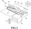
FIG. 1 is a schematic diagram of a printing apparatus that can be applied to one embodiment; -
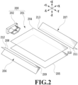
FIG. 2 is an exploded perspective diagram of a storage bag in one embodiment; -
FIG. 3 is a diagram explaining the occurrence of a vertical fold; -
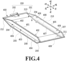
FIG. 4 is a perspective diagram of a storage bag, showing a coupling portion in one embodiment; -
FIG. 5 is a diagram explaining a coupling portion in one embodiment; -
FIG. 6A is a plan diagram showing part of an area VI inFIG. 5 ; -
FIG. 6B is a cross-sectional diagram along a VIB-VIB line inFIG. 6A ; -
FIG. 6C is a cross-sectional diagram along a VIC-VIC line inFIG. 6A ; -
FIG. 7 is a diagram showing a variant example of a coupling portion; and -
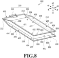
FIG. 8 is a perspective diagram of a storage bag, showing a coupling portion in one embodiment. -
FIG. 1 is a schematic diagram of aprinting apparatus 100 that can be applied to the present embodiment. - Coordinate axes in the drawings are explained. In the drawings referred to in the present specification, the X-direction and the Y-direction indicate two directions perpendicular to each other on a horizontal plane. The Z-direction indicates the vertical direction. The -Y-direction indicates the backward direction of the
printing apparatus 100, the +Y-direction indicates the forward direction, the -X-direction indicates the leftward direction in a case of being viewed from front, the +X-direction indicates the rightward direction, the +Z-direction indicates the upward direction, and the -Z-direction indicates the downward direction, respectively. The -Y-direction also indicates the downstream side in the conveyance direction of aprinting medium 101 and the +Y-direction also indicates the upstream side in the conveyance direction of theprinting medium 101. The Y-direction is called the conveyance direction and the X-direction is called the scanning direction of aprint head 103 as appropriate. The X-direction indicates the width of a storage bag 200 (seeFIG. 2 ) and the Y-direction corresponds to the length (depth) direction of thestorage bag 200 in a posture in which thestorage bag 200 is mounted on aliquid supply unit 106, to be described later, and the Z-direction corresponds to the height direction of thestorage bag 200. In the following explanation. unless described particularly, the upward, downward, leftward, and rightward directions indicate directions in the posture in which theprinting apparatus 100 and thestorage bag 200 are used in the normal state. - As shown in
FIG. 1 , theprinting apparatus 100 comprises aconveyance roller 102 conveying theprinting medium 101 in the conveyance direction. Theprinting apparatus 100 comprises theprint head 103 capable of ejecting liquid (for example, ink), acarriage 104 on which theprint head 103 can be mounted attachably and detachably, and twoguide rails 105 supporting thecarriage 104 slidably. Theprinting apparatus 100 comprises theliquid supply unit 106 for supplying liquid to theprint head 103, atube 107 connecting theprint head 103 and theliquid supply unit 106, and arestoration unit 108 for maintaining and restoring the performance of theprint head 103. - In the printing operation, the
printing apparatus 100 repeats the reciprocating movement (main scanning) of theprint head 103 and the conveyance (sub scanning) of theprinting medium 101 with each predetermined pitch. By causing theprint head 103 to selectively eject liquids of a plurality of colors and causing the liquids to land on theprinting medium 101 while in synchronization with these movements, printing for theprinting medium 101 is performed. - The
printing medium 101 is not limited as long as it is possible to cause liquid droplets to land on theprinting medium 101 and form an image thereon. For example, as theprinting medium 101, it is possible to use media of various materials and aspects, such as paper, cloth, optical disk label surface, plastic sheet, OHP sheet, and envelope. - By a drive unit (for example, motor not shown schematically, and the like) driving, the
carriage 104 reciprocates along the twoguide rails 105. Theprinting medium 101 that receives liquid ejected from a liquid ejection unit (not shown schematically) of theprint head 103 is conveyed by theconveyance roller 102 in the conveyance direction facing a liquid ejection surface of theprint head 103 and perpendicular to the movement direction of thecarriage 104. - The
print head 103 has a plurality of nozzle arrays for ejecting liquids of colors different from one another as a plurality of liquid ejection units. In accordance with the color of the liquid that is ejected from theprint head 103, a plurality ofindependent storage containers 109 having a discharge port 202 (seeFIG. 2 ) is mounted on theliquid supply unit 106 attachably and detachably. - The
storage container 109 includes afirst storage container 109A, asecond storage container 109B, athird storage container 109C, and afourth storage container 109D storing liquids of black, cyan, magenta, and yellow, respectively. The colors of liquid are not limited to the above-described four colors. In the following, in a case where it is not necessary to particularly distinguish thefirst storage container 109A, thesecond storage container 109B, thethird storage container 109C, and thefourth storage container 109D from one another, they are called thestorage container 109. - The
liquid supply unit 106 and theprint head 103 are connected by a plurality of thetubes 107 corresponding to each color. In the present embodiment, theliquid supply unit 106 and theprint head 103 are connected by the fourtubes 107 corresponding to each of the above-described four colors. - In the present embodiment, the
storage container 109 includes a rigid case and the storage bag 200 (seeFIG. 2 ) stored in the rigid case. Inside the rigid case, the storage bag 200 (seeFIG. 2 ) is positioned in a predetermined posture. - In the present embodiment, the shape of the rigid case is a tray type. The storage bag 200 (see
FIG. 2 ) is mounted in the tray-type rigid case attachably and detachably. However, the shape of the rigid case may be a box type. It is also possible to store the storage bag 200 (seeFIG. 2 ) inside the box-type rigid case attachably and detachably. - By a user advancing the rigid case of the
storage container 109 and mounting the rigid case on theliquid supply unit 106, it is made possible to independently supply the liquid of each color stored in the storage bag 200 (seeFIG. 2 ) to each nozzle array of theprint head 103. Theliquid supply unit 106 comprises a pump mechanism (not shown schematically). It is possible for the pump mechanism to suck in liquid from thestorage container 109 and send the liquid to theprint head 103. -
FIG. 2 is an exploded perspective diagram of thestorage bag 200 in the present embodiment. - As shown in
FIG. 2 , thestorage bag 200 comprises abag body 201 with flexibility capable of hermetically storing liquid and thedischarge port 202 discharging liquid to the outside from the inside of thebag body 201. Thedischarge port 202 is manufactured by injection molding. By the above-described pump mechanism driving, ink is sucked in from thedischarge port 202 and the ink is supplied to theprint head 103 via the tube 107 (seeFIG. 1 ). - The
bag body 201 includes atop surface film 204 located on the top surface side and anundersurface film 205 opposite to thetop surface film 204 and located on the undersurface side in a posture in which thebag body 201 is used. Thebag body 201 includes aleft surface film 206 connecting the end portion of thetop surface film 204 and the end portion of theundersurface film 205. Thestorage bag 200 includes aright surface film 207 opposite to theleft surface film 206 and connecting the end portion of thetop surface film 204 and the end portion of theundersurface film 205. - The
top surface film 204, theleft surface film 206, theundersurface film 205, and theright surface film 207 include a material suppressing leakage of liquid stored internally and likely to be coupled (in the present embodiment, likely to be thermally welded). Thetop surface film 204, theleft surface film 206, theundersurface film 205, and theright surface film 207 may be coupled by an adhesive agent. - As examples of the material of each of the
top surface film 204, theleft surface film 206, theundersurface film 205, and theright surface film 207, there are polyethylene, polypropylene and the like. By taking into consideration the gas-barrier property and the fastness property, it is also possible to use a multilayer film including a plurality of materials, such as aluminum, PET (polyethylene terephthalate), nylon and the like. - In a case where the
bag body 201 is formed, each of the top end portion of theleft surface film 206 and the top end portion of theright surface film 207 is coupled to each of the left and right end portions of thetop surface film 204. Then, each of the bottom end portion of theleft surface film 206 and the bottom end portion of theright surface film 207 is coupled to each of the left and right end portions of theundersurface film 205. As described above, in a case where thebag body 201 is formed, thetop surface film 204, theleft surface film 206, theundersurface film 205, and theright surface film 207 are coupled into the shape of a cylinder. - That is, at one of the openings (front side in
FIG. 2 ) in thebag body 201 coupled into the shape of a cylinder, thetop surface film 204 and theundersurface film 205 are coupled via the double-foldedleft surface film 206 and the double-foldedright surface film 207. Specifically, the left and right portions of thetop surface film 204 and theundersurface film 205 are coupled via afirst end portion 209 of afirst folding line 208 in theleft surface film 206 and asecond end portion 211 of asecond folding line 210 in theright surface film 207. On the other hand, the center portions of thetop surface film 204 and theundersurface film 205 are coupled directly without the intervention of another film. - At the other of the openings (depth side in
FIG. 2 ) in thebag body 201 coupled into the shape of a cylinder, thetop surface film 204 and theundersurface film 205 are coupled in a state where the double-foldedleft surface film 206, the double-foldedright surface film 207, and part of thedischarge port 202 are sandwiched. Specifically, the left and right portions of thetop surface film 204 and theundersurface film 205 are coupled via athird end portion 212 of thefirst folding line 208 and afourth end portion 213 of thesecond folding line 210. On the other hand, the center portions of thetop surface film 204 and theundersurface film 205 are coupled directly in a state where part of thedischarge port 202 is sandwiched. - In the present embodiment, the hermetically sealed
storage bag 200 is formed as described above. In thestorage bag 200, theleft surface film 206 and theright surface film 207 function as a gusset portion. -
FIG. 3 is a diagram explaining the occurrence of avertical fold 300. InFIG. 3 , thestorage bag 200 is shown in the posture in which thestorage bag 200 is used (that is, posture in which thestorage bag 200 is mounted on the liquid supply unit 106). - As shown in
FIG. 3 , in thestorage bag 200 before the start of its use (that is, in the initial state), in order to allow flexibility, liquid not less than 50% and not more than 80% of the maximum amount that can be stored is stored. The larger the amount of the remaining liquid in thestorage bag 200, the more thestorage bag 200 swells out. The more thestorage bag 200 swells out, the larger the angle formed by the upper side and the lower side with thefirst folding line 208 as a boundary becomes in theleft surface film 206. Also in theright surface film 207, as in theleft surface film 206, the angle formed by the upper side and the lower side with the second folding line 210 (not shown schematically inFIG. 3 ) as a boundary becomes large . - For example, in a case where the posture changes from the posture in which the
storage bag 200 is used to another different posture, it may happen sometimes that the liquid moves inside thestorage bag 200 and theleft surface film 206 and theright surface film 207 spread. Specifically, in a case where the brand-new storage bag 200 is mounted on the rigid case of the storage container 109 (seeFIG. 1 ), it may happen sometimes that thedischarge port 202 is directed upward in the direction of gravity by a user. In this case, inside thebag body 201, the liquid moves to a position distant from thedischarge port 202 and accumulates at the position. In a case where the posture of thestorage bag 200 changes as described above, theleft surface film 206 and theright surface film 207 are pushed and spread from the inside of thebag body 201 toward the outside. - As described above, the
left surface film 206 and theright surface film 207 function as a gusset portion and are capable of increasing the capacity of thebag body 201. However, each of one end portion in thetop surface film 204 and one end portion in theundersurface film 205 is coupled via each of thefirst end portion 209 and thesecond end portion 211. Then, each of the other end portion in thetop surface film 204 and the other end portion in theundersurface film 205 is coupled via each of thethird end portion 212 and thefourth end portion 213. Consequently, the range is limited in which theleft surface film 206 and theright surface film 207 can spread as a gusset portion. - In the
left surface film 206, as the angle of the fold toward the inside of thebag body 201 approaches 180 degrees (that is, as the fold disappears), thevertical fold 300 substantially perpendicular to thefirst folding line 208 becomes more likely to occur. On the other hand, in theright surface film 207 also, as the angle of the fold toward the inside of thebag body 201 approaches 180 degrees (that is, as the fold disappears), thevertical fold 300 substantially perpendicular to thesecond folding line 210 becomes more likely to occur. - In a case where the
vertical fold 300 occurs, while the liquid is being used and theleft surface film 206 and theright surface film 207 are being folded up, thevertical fold 300 serves as a resistance to the folding and blocks smooth shrinkage of thestorage bag 200. - Originally, as the amount of remaining liquid decreases, each of the
left surface film 206 and theright surface film 207 is folded up along each of thefirst folding line 208 and thesecond folding line 210 and the capacity of thestorage bag 200 is reduced. However, in a case where thevertical fold 300 occurs, the folding of theleft surface film 206 and theright surface film 207 is blocked and it becomes difficult to use up the liquid. In order to suppress the occurrence of thevertical fold 300 such as this, in the present embodiment, the shape of the coupling portion of each film is allowed to have a feature. -
FIG. 4 is a perspective diagram of thestorage bag 200, showing acoupling portion 400 of thebag body 201 in the present embodiment. - As shown in
FIG. 4 , thebag body 201 comprises thecoupling portion 400 at which thetop surface film 204, theleft surface film 206, theright surface film 207, and theundersurface film 205 are coupled. As described above, in the present embodiment, thetop surface film 204, theleft surface film 206, theright surface film 207, and theundersurface film 205 are thermally welded at thecoupling portion 400. That is, in the present embodiment, thecoupling portion 400 is a welding area. - The
coupling portion 400 includes afirst area 401 coupling the end portion of theleft surface film 206 and the end portion of thetop surface film 204 along the entire area in a first direction (Y-direction) and a firstconvex portion 402 configured to protrude toward the inside of thetop surface film 204 from thefirst area 401. Thecoupling portion 400 includes asecond area 403 coupling the end portion of theleft surface film 206 and the end portion of theundersurface film 205 along the entire area in the first direction (Y-direction) and a secondconvex portion 404 configured to protrude toward the inside of theundersurface film 205 from thesecond area 403. - The
coupling portion 400 includes athird area 405 coupling the end portion of theright surface film 207 and the end portion of thetop surface film 204 along the entire area in the first direction (Y-direction) and a thirdconvex portion 406 configured to protrude toward the inside of thetop surface film 204 from thethird area 405. Thecoupling portion 400 includes afourth area 407 coupling the end portion of theright surface film 207 and the end portion of theundersurface film 205 along the entire area in the first direction (Y-direction) and a fourthconvex portion 408 configured to protrude toward the inside of theundersurface film 205 from thefourth area 407. In the present embodiment, the first direction (Y-direction) is the direction from the bottom portion of thebag body 201 toward thedischarge port 202. - Further, it is preferable for the first
convex portion 402, the secondconvex portion 404, the thirdconvex portion 406, and the fourthconvex portion 408 to be provided at the same position in the Y-direction. According to this configuration, it is made easy to suppress the occurrence of the vertical fold 300 (seeFIG. 3 ) extending along the Z-direction. As long as it is possible to suppress the occurrence of the vertical fold 300 (seeFIG. 3 ), the position at which the firstconvex portion 402, the secondconvex portion 404, the thirdconvex portion 406, and the fourthconvex portion 408 are provided may not be the same position in the Y-direction. - Further, in a case where the
top surface film 204, theleft surface film 206, theright surface film 207, and theundersurface film 205 are coupled, a coupling tool (not shown schematically) coupling these four films while pressing them together is used. - In the present embodiment, as the coupling tool, a welding tool (not shown schematically) welding the
top surface film 204, theleft surface film 206, theright surface film 207, and theundersurface film 205 while pressing them together is used. Specifically, by designing part of the pressing surface of the welding tool the same shape as that of the firstconvex portion 402, the secondconvex portion 404, the thirdconvex portion 406, and the fourthconvex portion 408, it is possible to thermally weld these four films together while providing these four convex portions. According to the welding method such as this, it is possible to form the shape of thecoupling portion 400 without increasing the number of processes. -
FIG. 5 is a diagram explaining thecoupling portion 400 in the present embodiment. - As shown in
FIG. 5 , the firstconvex portion 402 in thecoupling portion 400 has afirst width 501, which is the length in the first direction (Y-direction), and afirst protrusion amount 502, which is the length in a second direction (X-direction). Like the firstconvex portion 402, the second convex portion 404 (not shown schematically inFIG. 5 ) also has a second width (not shown schematically inFIG. 5 ), which is the length in the first direction (Y-direction), and a second protrusion amount 605 (seeFIG. 6C ) protruding in the second direction (X-direction) from thesecond area 403. - As shown in
FIG. 5 , the thirdconvex portion 406 has athird width 503, which is the length in the first direction (Y-direction), and athird protrusion amount 504 protruding along the second direction (X-direction) from thethird area 405. Like the thirdconvex portion 406, the fourth convex portion 408 (not shown schematically inFIG. 5 ) also has a fourth width (not shown schematically inFIG. 5 ), which is the length in the first direction (Y-direction), and a fourth protrusion amount (not shown schematically inFIG. 5 ) protruding in the second direction (X-direction) from the fourthconvex portion 408. - The
first width 501, the second width, thethird width 503, and the fourth width are not less than about 5 mm and not more than about 30 mm. Thefirst protrusion amount 502, the second protrusion amount, thethird protrusion amount 504, and the fourth protrusion amount are not less than about 5 mm and not more than about 30 mm. - As shown in
FIG. 5 , it is preferable for each of a plurality of the firstconvex portions 402 to be provided within a range not less than about 10 mm and not more than about 70 mm from each of thefist end portion 209 and thethird end portion 212 toward the inside of thefirst folding line 208. Like the firstconvex portion 402, it is preferable for each of a plurality of the second convex portions 404 (not shown schematically inFIG. 5 ) to be provided within a range not less than about 10 mm and not more than about 70 mm from each of thefist end portion 209 and thethird end portion 212 toward the inside of thefirst folding line 208. - As shown in
FIG. 5 , it is preferable for each of a plurality of the thirdconvex portions 406 to be provided within a range not less than about 10 mm and not more than about 70 mm from each of thesecond end portion 211 and thefourth end portion 213 toward the inside of thesecond folding line 210. Like the thirdconvex portion 406, it is preferable for each of a plurality of the fourth convex portions 408 (not shown schematically inFIG. 5 ) to be provided within a range not less than about 10 mm and not more than about 70 mm from each of thesecond end portion 211 and thefourth end portion 213 toward the inside of thesecond folding line 210. - The reason is that by providing the above-described plurality of the convex portions within the above-described range, it is possible to efficiently suppress the occurrence of the
vertical fold 300. For example, in a case where the bottom portion (end portion on the side in the -Y-direction) of thestorage bag 200 is directed downward in the direction of gravity, the liquid gathers downward. In view of that theleft surface film 206 and theright surface film 207 spread at the end portion on the side in the Y-direction in thestorage bag 200 and thevertical fold 300 is likely to occur, by concentratedly providing each convex portion within the range not less than about 10 mm and not more than 70 mm from the bottom portion toward the inside of each of thefirst folding line 208 and thesecond folding line 210, it is possible to efficiently suppress the occurrence of thevertical fold 300. - The number of convex portions described above and the position of each convex portion are not limited to the example of the present embodiment. It is possible to determine the number of convex portions and the position thereof described above in accordance with the tendency of the position and the number at which and with which the
vertical fold 300 occurs. -
FIG. 6A is a plan diagram showing an area VI inFIG. 5 . - As shown in
FIG. 6A , it is desirable for thefirst protrusion amount 502 in the firstconvex portion 402 to be about two thirds or less of the shortest distance from thefirst area 401 to thefirst folding line 208. -
FIG. 6B is a cross-sectional diagram along a VIB-VIB line inFIG. 6A . InFIG. 6B , a state where the amount of remaining liquid is small is shown. The solid-line portion inFIG. 6B shows the posture in which thestorage bag 200 is used (posture in which thestorage bag 200 is placed horizontally). On the other hand, the broken-line portion inFIG. 6B shows the posture, which is moved from the posture in which thestorage bag 200 is place horizontally, and in which the discharge port 202 (not shown schematically inFIG. 6B ) is held upright so as to face upward. - As shown in the solid-line portion in
FIG. 6B , in the posture in which thestorage bag 200 is used, thebag body 201 has afirst distance 601 from thetop surface film 204 to theundersurface film 205. In the posture in which thestorage bag 200 is used, thebag body 201 has afirst angle 611 formed by the upper side and the lower side of theleft surface film 206 with thefirst folding line 208 as a boundary. - As shown in the broken-line portion in
FIG. 6B , in the state of thestorage bag 200 where thedischarge port 202 is held upright so as to face upward, thebag body 201 has asecond distance 602 from thetop surface film 204 to theundersurface film 205. Thesecond distance 602 is greater than thefirst distance 601. - In the state of the
storage bag 200 where thedischarge port 202 is held upright so as to face upward, theleft surface film 206 opens. Then, thebag body 201 has asecond angle 612 formed by the upper side and the lower side of theleft surface film 206 with thefirst folding line 208 as a boundary. Thesecond angle 612 is larger than thefirst angle 611. - For example, in a case where the posture in which the
storage bag 200 is used changes to the posture in which thedischarge port 202 is held upright so as to face upward, the ink within thebag body 201 moves in the direction of gravity. Because of this, at the bottom portion of thestorage bag 200, theleft surface film 206 swells out in the direction in which theleft surface film 206 opens against thefirst folding line 208. By theleft surface film 206 opening as described above, thesecond distance 602 from thetop surface film 204 to theundersurface film 205 becomes greater than thefirst distance 601 before theleft surface film 206 opens. -
FIG. 6C is a cross-sectional diagram along a VIC-VIC line inFIG. 6A . The solid-line portion inFIG. 6C shows the state where thestorage bag 200 is used (state where thestorage bag 200 is placed horizontally). On the other hand, the broken-line portion inFIG. 6C shows the posture after thestorage bag 200 is moved from the posture in which thestorage bag 200 is placed horizontally and the discharge port 202 (not shown schematically inFIG. 6C ) is held upright so as to face upward. InFIG. 6C , it is assumed that the amount of remaining liquid in each of the solid-line portion and the broken-line portion is the same as the amount of remaining liquid in each of the solid-line portion and the broken-line portion shown inFIG. 6B . - As shown in the solid-line portion in
FIG. 6C , at the portion at which the firstconvex portion 402 and the secondconvex portion 404 in theleft surface film 206 are provided, thebag body 201 has athird distance 603 from thetop surface film 204 to theundersurface film 205. However, the firstconvex portion 402 and the secondconvex portion 404 are provided, and therefore, thethird distance 603 is smaller than the first distance 601 (seeFIG. 6B ). In the posture in which thestorage bag 200 is used, thebag body 201 has athird angle 613 formed by the upper side and the lower side of theleft surface film 206 with thefirst folding line 208 as a boundary. - As shown in the broken-line portion in
FIG. 6C , in the state of thestorage bag 200 where thedischarge port 202 is held upright so as to face upward, thebag body 201 has afourth distance 604 from thetop surface film 204 to theundersurface film 205. However, thefourth distance 604 is greater than thethird distance 603. Then, the firstconvex portion 402 and the secondconvex portion 404 are provided, and therefore, thefourth distance 604 is smaller than the second distance 602 (seeFIG. 6B ). - In the state of the
storage bag 200 where thedischarge port 202 is held upright so as to face upward, theleft surface film 206 opens and thebag body 201 has afourth angle 614 formed by the upper side and the lower side of theleft surface film 206 with thefirst folding line 208 as a boundary. Thefourth angle 614 is larger than thethird angle 613. As described above, in theleft surface film 206, the portion at which the firstconvex portion 402 and the secondconvex portion 404 are provided has a movable area in the ±Y-direction smaller than that of the portion at which the firstconvex portion 402 or the secondconvex portion 404 is not provided. That is, as the results of theleft surface film 206 being suppressed from opening, thefourth distance 604 at the portion at which the firstconvex portion 402 and the secondconvex portion 404 are provided becomes smaller than the second distance 602 (seeFIG. 6B ). - As described above, as the angle of the
left surface film 206 approaches 180 degrees, the possibility that thevertical fold 300 occurs becomes strong. However, in theleft surface film 206, it is possible to make the distance from thetop surface film 204 to theundersurface film 205 at the portion at which the firstconvex portion 402 and the secondconvex portion 404 are provided shorter than that at the portion at which the firstconvex portion 402 or the secondconvex portion 404 is not provided. That is, it is possible to suppress the occurrence of the vertical fold 300 (not shown schematically inFIG. 6C ) by providing the firstconvex portion 402 and the secondconvex portion 404 so as to increase the strength of theleft surface film 206. - Further, also in the right surface film 207 (not shown schematically in
FIG. 6C ), as in theleft surface film 206, it is possible to suppress the occurrence of the vertical fold 300 (not shown schematically inFIG. 6C ). - As explained above, at the coupling portion on the lateral face in the storage bag of the present embodiment, the convex portion is provided. At the coupling portion on the lateral face, the movable area of the lateral face (gusset portion) is regulated at the portion at which the convex portion is provided compared to the portion at which the convex position is not provided, and therefore, the possibility of the occurrence of the vertical fold on the lateral face is suppressed.
- Consequently, according to the storage bag of the present embodiment, it is possible to suppress the occurrence of the vertical fold at the gusset portion.
-
FIG. 7 is a diagram showing a variant example of thecoupling portion 400 in the first embodiment. - As shown in
FIG. 7 , it is preferable for a plurality of the firstconvex portions 402, a plurality of the second convex portions 404 (not shown schematically inFIG. 7 ), a plurality of the thirdconvex portions 406, and a plurality of the fourth convex portions 408 (not shown schematically inFIG. 7 ) to be provided concentratedly at positions at which thevertical fold 300 is likely to occur. - In the present variant example, within a range not less than about 10 mm and not more than about 70 mm from the
first end portion 209 toward the inside of thefirst folding line 208, the two firstconvex portions 402 and the two second convex portions 404 (not shown schematically inFIG. 7 ) are provided. Within a range not less than about 10 mm and not more than about 70 mm from thethird end portion 212 toward the inside of thefirst folding line 208, the two firstconvex portions 402 and the two second convex portions 404 (not shown schematically inFIG. 7 ) are provided. - On the other hand, within a range not less than about 10 mm and not more than about 70 mm from the
second end portion 211 toward the inside of thesecond folding line 210, the two thirdconvex portions 406 and the two fourth convex portions 408 (not shown schematically inFIG. 7 ) are provided. Within a range not less than about 10 mm and not more than about 70 mm from thefourth end portion 213 toward the inside of thesecond folding line 210, the two thirdconvex portions 406 and the two fourth convex portions 408 (not shown schematically inFIG. 7 ) are provided. - In the example in
FIG. 7 , the size of each of the firstconvex portion 402, the secondconvex portion 404, the thirdconvex portion 406, and the fourthconvex portion 408 is the same but the size of each of them may be changed. For example, the protrusion amount of each of the firstconvex portion 402, the secondconvex portion 404, the thirdconvex portion 406, and the fourthconvex portion 408 may be changed, or the width of each of the firstconvex portion 402, the secondconvex portion 404, the thirdconvex portion 406, and the fourthconvex portion 408 may be changed. Of course, it may also be possible to provide the firstconvex portion 402, the secondconvex portion 404, the thirdconvex portion 406, and the fourthconvex portion 408 whose sizes are different in combination. - Further, the influence of the
vertical fold 300 that occurs at a position distant from thedischarge port 202 on the used-up property of liquid is greater than that of thevertical fold 300 that occurs at a position close to thedischarge port 202. Consequently, it may be possible to provide the firstconvex portion 402, the secondconvex portion 404, the thirdconvex portion 406, and the fourthconvex portion 408 only at positions distant from thedischarge port 202 and it is not necessary to provide them in the vicinity of thedischarge port 202. - By providing the first
convex portion 402 and the thirdconvex portion 406, the spread of the left surface film 206 (not shown schematically inFIG. 7 ) and the right surface film 207 (not shown schematically inFIG. 7 ) is suppressed partially. Because of this, it is considered that the maximum amount of liquid that can be stored in thestorage bag 200 is reduced. - However, in a case where the size of each of the first
convex portion 402 and the secondconvex portion 404 is the above-described size and the number of firstconvex portions 402 and the number of secondconvex portions 404 are each five or less for thefirst folding line 208, there is not a great influence on the storage amount of liquid. Similarly, also in a case where the size of each of the thirdconvex portion 406 and the fourthconvex portion 408 is the above-described size and the number of thirdconvex portions 406 and the number of fourthconvex portions 408 are each five or less for thesecond folding line 210, there is not a great influence on the storage amount of liquid. That is, in a case where the number of convex portions at the coupling portion for one folding line is ten or less and the size of each of these convex portions is the above-described size, there is not a great influence on the storage amount of liquid. - Consequently, it may be possible to appropriately determine the number of first
convex portions 402, the number of secondconvex portions 404, the number of thirdconvex portions 406, and the number of fourthconvex portions 408 in accordance with the maximum amount of liquid that thestorage bag 200 stores, the size of the gusset portion, the material of film and the like. - Further, it may also be possible to determine an interval D between adjacent ones of the plurality of the first
convex portions 402, an interval D between adjacent ones of the plurality of the secondconvex portions 404, an interval D between adjacent ones of the plurality of the thirdconvex portions 406, and an interval D between adjacent ones of the plurality of the fourthconvex portions 408 in accordance with the amount of liquid that is desired to be stored, or the like. - Further, it is preferable for the first
convex portion 402 and the secondconvex portion 404 to be provided at positions symmetric with respect to thefirst folding line 208 in a state where thestorage bag 200 is viewed from the left lateral face thereof. Similarly, it is preferable for the thirdconvex portion 406 and the fourthconvex portion 408 to be provided at positions symmetric with respect to thesecond folding line 210 in a state where thestorage bag 200 is viewed from the right lateral face thereof. - It may also be possible to provide the first
convex portion 402 and the secondconvex portion 404 at positions asymmetric with respect to thefirst folding line 208 in a state where thestorage bag 200 is viewed from the left lateral face thereof. Similarly, it may also be possible to provide the thirdconvex portion 406 and the fourthconvex portion 408 at positions asymmetric with respect to thesecond folding line 210 in a state where thestorage bag 200 is viewed from the right lateral face. - With the variant example of the storage bag as described above, it is possible to suppress the occurrence of a vertical fold at the gusset portion.
- In the above-described embodiment, explanation is given by supposing a case where a vertical fold occurs at the gusset portion on the left and right lateral faces, but a configuration in which the gusset portion is arranged at the bottom face may also be accepted. In a case where a vertical fold occurs at the gusset portion at the bottom face, it is also possible to apply the technique of the present disclosure. In the following explanation, to the configuration the same as or corresponding to that of the first embodiment, the same symbol is attached and at the same time explanation thereof is omitted and different points are explained mainly.
-
FIG. 8 is a perspective diagram of asecond storage bag 800, showing thecoupling portion 400 of thebag body 201 in the present embodiment. - As shown in
FIG. 8 , thebag body 201 of the present embodiment comprises abottom face film 801 functioning as a gusset portion. As examples of the material of thebottom face film 801, there are polyethylene, polypropylene and the like. In view of the gas-barrier property and the fastness property of thebottom face film 801, it is also possible to use a multilayer film including a plurality of materials, such as aluminum, PET, and nylon. By comprising thebottom face film 801, it is possible to make the capacity of thebag body 201 of the present embodiment larger than that of the first embodiment. - In the present embodiment, the
top surface film 204 and theundersurface film 205 are connected via thebottom face film 801 double-folded along athird folding line 802. - The
coupling portion 400 of the present embodiment includes afifth area 803 coupling the end portion of thebottom face film 801 and the end portion of thetop surface film 204 along the entire area in the second direction (X-direction) and a fifthconvex portion 804 configured to protrude toward the inside of thetop surface film 204 from thefifth area 803. Thecoupling portion 400 of the present embodiment includes asixth area 805 coupling the end portion of thebottom face film 801 and the end portion of theundersurface film 205 along the entire area in the second direction (X-direction) and a sixthconvex portion 806 configured to protrude toward the inside of theundersurface film 205 from thesixth area 805. - Depending on the posture of the
bag body 201, it is considered that a vertical fold occurs in thebottom face film 801. - However, according to the configuration of the present embodiment, in the
bottom face film 801, the movable area of the portion at which the fifthconvex portion 804 and the sixthconvex portion 806 are provided is smaller than that of the portion at which the fifthconvex portion 804 or the sixthconvex portion 806 is not provided. That is, the distance from thetop surface film 204 to theundersurface film 205 at the portion at which the fifthconvex portion 804 and the sixthconvex portion 806 are provided is shorter than the distance at the portion at which the fifthconvex portion 804 or the sixthconvex portion 806 is not provided. As above, in thebottom face film 801 of the present embodiment, as the results of the movable area being suppressed, as in the case of theleft surface film 206 and theright surface film 207, the occurrence of a vertical fold is suppressed. - Consequently, with the
second storage bag 800, even in a case where the bottom face functions as a gusset portion, it is possible to suppress the occurrence of a vertical fold in the bottom face. - In the above embodiments, explanation is given by supposing the case where liquid is ink, but the liquid that can be applied to the technique of the present disclosure is not limited to ink. That is, it is possible to use various printing liquids including the processing liquid used for the purpose of improving the fixing property of ink, reducing gloss unevenness, improving scratch resistance in a printing medium, and so on.
- In the above embodiments, explanation is given by supposing the case where a vertical fold occurs because the discharge port is directed upward in the direction of gravity by a user in attaching a brand-new storage bag to a rigid case. In addition to this, a vertical fold may also occur in a case where the storage bag not used up yet is removed from the rigid case and the storage bag is stored temporarily by a user, and then the storage bag is mounted again on the rigid case.
- Further, there is also a possibility that a vertical fold occurs in a case where a user replenishes the storage bag with liquid by injecting the liquid into the inside of the storage bag from the discharge port.
- According to the storage bag of the present disclosure, it is possible to suppress the occurrence of a vertical fold at the gusset portion.
- While the present disclosure has been described with reference to exemplary embodiments, it is to be understood that the disclosure is not limited to the disclosed exemplary embodiments. The scope of the following claims is to be accorded the broadest interpretation so as to encompass all such variations and equivalent structures and functions.
Claims (17)
- A storage bag (200) comprising a bag body (201) and a discharge port (202) for discharging liquid stored in the bag body (201), characterized in thatthe bag body (201) includes a first surface portion (204), a second surface portion (205) opposite to the first surface portion (204), a third surface portion (206) configured to serve as a gusset portion configured to connect the first surface portion (204) and the second surface portion (205), and a fourth surface portion (207) opposite to the third surface portion (206) and configured to serve as a gusset portion configured to connect the first surface portion (204) and the second surface portion (205),the first surface portion (204) and the third surface portion (206) are coupled by a first coupling portion (401) configured to extend in a first direction,the first surface portion (204) and the fourth surface portion (207) are coupled by a second coupling portion (405) configured to extend in the first direction,the first coupling portion (401) includes a first convex portion (402) configured to protrude toward the inside of the first surface portion (204) along a second direction intersecting the first direction,the second coupling portion (405) includes a second convex portion (406) configured to protrude toward the inside of the first surface portion (204) along the second direction,the second surface portion (205) and the third surface portion (206) are coupled by a third coupling portion (403) configured to extend in the first direction,the second surface portion (205) and the fourth surface portion (207) are coupled by a fourth coupling portion (407) configured to extend in the first direction,the third coupling portion (403) includes a third convex portion (404) configured to protrude toward the inside of the second surface portion (205) along the second direction,the fourth coupling portion (407) includes a fourth convex portion (408) configured to protrude toward the inside of the second surface portion (205) along the second direction,the first convex portion (402) and the third convex portion (404) are located at the same position in the first direction, andthe second convex portion (406) and the fourth convex portion (408) are located at the same position in the first direction.
- The storage bag (200) according to claim 1, characterized in thatat the first coupling portion (401), the first surface portion (204) and the third surface portion (206) are coupled by welding or an adhesive agent andat the second coupling portion (405), the first surface portion (204) and the fourth surface portion (207) are coupled by welding or an adhesive agent.
- The storage bag (200) according to claim 1 or 2, characterized in thatat the first coupling portion (401), a distance the first convex portion (402) extends in the first direction and in the second direction is not less than 5 mm and not more than 30 mm andat the second coupling portion (405), a distance the second convex portion (406) extends in the first direction and in the second direction is not less than 5 mm and not more than 30 mm.
- The storage bag (200) according to any one of claims 1 to 3, characterized in thatthe first convex portion (402) is provided within a range extending not less than 10 mm and not more than 70 mm in the first direction from the end portion (209) of the third surface portion (206) toward the inside of the third surface portion (206) andthe second convex portion (406) is provided within a range extending not less than 10 mm and not more than 70 mm in the first direction from the end portion (211) of the fourth surface portion (207) toward the inside of the fourth surface portion (207).
- The storage bag (200) according to any one of claims 1 to 4, characterized in thatat the third coupling portion (403), the second surface portion (205) and the third surface portion (206) are coupled by welding or an adhesive agent andat the fourth coupling portion (407), the second surface portion (205) and the fourth surface portion (207) are coupled by welding or an adhesive agent.
- The storage bag (200) according to any one of claims 1 to 5, characterized in thatat the third coupling portion (403), a distance the third convex portion (404) extends in the first direction and in the second direction is not less than 5 mm and not more than 30 mm andat the fourth coupling portion (407), a distance the fourth convex portion (408) extends in the first direction and in the second direction is not less than 5 mm and not more than 30 mm.
- The storage bag (200) according to any one of claims 1 to 6, characterized in thatthe third convex portion (404) is provided within a range extending not less than 10 mm and not more than 70 mm in the first direction from the end portion (209) of the third surface portion (206) toward the inside of the third surface portion (206) andthe fourth convex portion (408) is provided within a range extending not less than 10 mm and not more than 70 mm in the first direction from the end portion (211) of the fourth surface portion (207) toward the inside of the fourth surface portion (207).
- The storage bag (200) according to any one of claims 1 to 7, characterized in thatthe total number of the number of first convex portions (402) and the number of third convex portions (404) is ten or less andthe total number of the number of second convex portions (406) and the number of fourth convex portions (408) is ten or less.
- The storage bag (200) according to any one of claims 1 to 8, characterized in that
the first direction is a direction toward the discharge port (202) from a bottom portion of the bag body (201). - The storage bag (200) according to any one of claims 1 to 9, characterized in that
the first surface portion (204), the second surface portion (205), the third surface portion (206), and the fourth surface portion (207) are configured by a film including at least one of polyethylene, polypropylene, aluminum, polyethylene terephthalate, and nylon. - The storage bag (200) according to any one of claims 1 to 10, characterized in that
as liquid is discharged from the bag body (201), the third surface portion (206) and the fourth surface portion (207) are folded up along a folding line extending in the first direction. - The storage bag (200) according to any one of claims 1 to 11, characterized in thatthe bag body (201) further includes a fifth surface portion (801) configured to serve as a gusset portion configured to connect the first surface portion (204), the second surface portion (205), the third surface portion (206), and the fourth surface portion (207),the first surface portion (204) and the fifth surface portion (801) are coupled by a fifth coupling portion (803) configured to extend in the second direction,the second surface portion (205) and the fifth surface portion (801) are coupled by a sixth coupling portion (805) configured to extend in the second direction,the fifth coupling portion (803) includes a fifth convex portion (804) configured to protrude toward the inside of the first surface portion (204) along the first direction, andthe sixth coupling portion (805) includes a sixth convex portion (806) configured to protrude toward the inside of the first surface portion (204) along the first direction.
- The storage bag (200) according to claim 12, characterized in that
the fifth convex portion (804) and the sixth convex portion (806) are located at the same position in the second direction. - The storage bag (200) according to claim 12 or 13, characterized in thatat the fifth coupling portion (803), the first surface portion (204) and the fifth surface portion (801) are coupled by welding or an adhesive agent andat the sixth coupling portion (805), the second surface portion (205) and the fifth surface portion (801) are coupled by welding or an adhesive agent.
- The storage bag (200) according to any one of claims 12 to 14, characterized in that
the fifth surface portion (801) is configured by a film including at least one of polyethylene, polypropylene, aluminum, polyethylene terephthalate, and nylon. - The storage bag (200) according to any one of claims 12 to 15, characterized in that
as liquid is discharged from the bag body (201), the fifth surface portion (801) is folded up along a folding line extending in the second direction. - A printing apparatus (100) comprising:a mounting unit capable of mounting a storage bag (200) comprising a bag body (201) and a discharge port (202) for discharging liquid stored in the bag body (201); anda print head (103) capable of printing an image on a printing medium by ejecting liquid discharged from the discharge port (202), characterized in thatthe bag body (201) includes a first surface portion (204), a second surface portion (205) opposite to the first surface portion (204), a third surface portion (206) configured to serve as a gusset portion configured to connect the first surface portion (204) and the second surface portion (205), and a fourth surface portion (207) opposite to the third surface portion (206) and configured to serve as a gusset portion configured to connect the first surface portion (204) and the second surface portion (205),the first surface portion (204) and the third surface portion (206) are coupled by a first coupling portion (401) configured to extend in a first direction,the first surface portion (204) and the fourth surface portion (207) are coupled by a second coupling portion (405) configured to extend in the first direction,the first coupling portion (401) includes a first convex portion (402) configured to protrude toward the inside of the first surface portion (204) along a second direction intersecting the first direction,the second coupling portion (405) includes a second convex portion (406) configured to protrude toward the inside of the first surface portion (204) along the second direction,the second surface portion (205) and the third surface portion (206) are coupled by a third coupling portion (403) configured to extend in the first direction,the second surface portion (205) and the fourth surface portion (207) are coupled by a fourth coupling portion (407) configured to extend in the first direction,the third coupling portion (403) includes a third convex portion (404) configured to protrude toward the inside of the second surface portion (205) along the second direction,the fourth coupling portion (407) includes a fourth convex portion (408) configured to protrude toward the inside of the second surface portion (205) along the second direction,the first convex portion (402) and the third convex portion (404) are located at the same position in the first direction, andthe second convex portion (406) and the fourth convex portion (408) are located at the same position in the first direction.
Applications Claiming Priority (1)
| Application Number | Priority Date | Filing Date | Title |
|---|---|---|---|
| JP2023196475A JP2025082915A (en) | 2023-11-20 | 2023-11-20 | Storage bag and recording apparatus |
Publications (1)
| Publication Number | Publication Date |
|---|---|
| EP4556244A1 true EP4556244A1 (en) | 2025-05-21 |
Family
ID=93563648
Family Applications (1)
| Application Number | Title | Priority Date | Filing Date |
|---|---|---|---|
| EP24213286.8A Pending EP4556244A1 (en) | 2023-11-20 | 2024-11-15 | Storage bag and printing apparatus |
Country Status (5)
| Country | Link |
|---|---|
| US (1) | US20250162324A1 (en) |
| EP (1) | EP4556244A1 (en) |
| JP (1) | JP2025082915A (en) |
| KR (1) | KR20250074624A (en) |
| CN (1) | CN120019959A (en) |
Citations (3)
| Publication number | Priority date | Publication date | Assignee | Title |
|---|---|---|---|---|
| JP2012016825A (en) | 2010-07-06 | 2012-01-26 | Seiko Epson Corp | Liquid storage body and liquid storage container |
| US9333756B2 (en) * | 2014-06-30 | 2016-05-10 | Kyocera Document Solutions Inc. | Ink container and inkjet recording apparatus including the same |
| US20200094566A1 (en) * | 2018-09-21 | 2020-03-26 | Seiko Epson Corporation | Liquid housing container, liquid housing apparatus, and liquid ejecting apparatus |
-
2023
- 2023-11-20 JP JP2023196475A patent/JP2025082915A/en active Pending
-
2024
- 2024-11-14 US US18/948,382 patent/US20250162324A1/en active Pending
- 2024-11-15 EP EP24213286.8A patent/EP4556244A1/en active Pending
- 2024-11-15 CN CN202411630396.8A patent/CN120019959A/en active Pending
- 2024-11-19 KR KR1020240164796A patent/KR20250074624A/en active Pending
Patent Citations (3)
| Publication number | Priority date | Publication date | Assignee | Title |
|---|---|---|---|---|
| JP2012016825A (en) | 2010-07-06 | 2012-01-26 | Seiko Epson Corp | Liquid storage body and liquid storage container |
| US9333756B2 (en) * | 2014-06-30 | 2016-05-10 | Kyocera Document Solutions Inc. | Ink container and inkjet recording apparatus including the same |
| US20200094566A1 (en) * | 2018-09-21 | 2020-03-26 | Seiko Epson Corporation | Liquid housing container, liquid housing apparatus, and liquid ejecting apparatus |
Also Published As
| Publication number | Publication date |
|---|---|
| US20250162324A1 (en) | 2025-05-22 |
| KR20250074624A (en) | 2025-05-27 |
| JP2025082915A (en) | 2025-05-30 |
| CN120019959A (en) | 2025-05-20 |
Similar Documents
| Publication | Publication Date | Title |
|---|---|---|
| US11840087B2 (en) | Ink jet recording apparatus capable of suppressing overflow of ink from an absorber even if the apparatus is arranged at an angle | |
| US6840610B2 (en) | Liquid container, ink jet cartridge and ink jet printing apparatus | |
| US10239315B2 (en) | Liquid ejecting apparatus | |
| JP5176967B2 (en) | Ink cartridge and image forming apparatus | |
| KR102661718B1 (en) | Inkjet printing apparatus and ink tank | |
| US20080225093A1 (en) | Liquid storage container and refilling method using the same | |
| JP5621361B2 (en) | Liquid container and liquid container | |
| JP5720273B2 (en) | Ink container and image forming apparatus | |
| US9346278B2 (en) | Packaging tray and packaging body | |
| JP5353565B2 (en) | Liquid container and image forming apparatus | |
| JP5210149B2 (en) | Ink container and ink supply method | |
| US20250162324A1 (en) | Storage bag and printing apparatus | |
| JP5440264B2 (en) | Ink cartridge and image forming apparatus | |
| US11833824B2 (en) | Liquid storing container and printing apparatus | |
| US20220169043A1 (en) | Recording device | |
| JP5004121B2 (en) | Printer liquid bag mounting mechanism | |
| JP5201078B2 (en) | Recording agent container and image forming apparatus | |
| JP7268443B2 (en) | printer | |
| JP2011148255A (en) | Printer | |
| US20250282145A1 (en) | Liquid container production method, liquid container, and liquid ejection apparatus | |
| US11926164B2 (en) | Recording apparatus and recording head | |
| US20250346035A1 (en) | Ink container and liquid ejection apparatus | |
| JP2021084379A (en) | Ink pack, ink container comprising the same, and ink jet recording device | |
| US20250340063A1 (en) | Ink storage container and ink ejection apparatus | |
| JP2013086487A (en) | Liquid storage container and image forming device |
Legal Events
| Date | Code | Title | Description |
|---|---|---|---|
| PUAI | Public reference made under article 153(3) epc to a published international application that has entered the european phase |
Free format text: ORIGINAL CODE: 0009012 |
|
| STAA | Information on the status of an ep patent application or granted ep patent |
Free format text: STATUS: THE APPLICATION HAS BEEN PUBLISHED |
|
| AK | Designated contracting states |
Kind code of ref document: A1 Designated state(s): AL AT BE BG CH CY CZ DE DK EE ES FI FR GB GR HR HU IE IS IT LI LT LU LV MC ME MK MT NL NO PL PT RO RS SE SI SK SM TR |
|
| STAA | Information on the status of an ep patent application or granted ep patent |
Free format text: STATUS: REQUEST FOR EXAMINATION WAS MADE |
|
| 17P | Request for examination filed |
Effective date: 20251121 |