EP4556238A1 - Ink container, ink container set and printing system - Google Patents
Ink container, ink container set and printing system Download PDFInfo
- Publication number
- EP4556238A1 EP4556238A1 EP23209642.0A EP23209642A EP4556238A1 EP 4556238 A1 EP4556238 A1 EP 4556238A1 EP 23209642 A EP23209642 A EP 23209642A EP 4556238 A1 EP4556238 A1 EP 4556238A1
- Authority
- EP
- European Patent Office
- Prior art keywords
- key portion
- ink
- ink container
- key
- wall
- Prior art date
- Legal status (The legal status is an assumption and is not a legal conclusion. Google has not performed a legal analysis and makes no representation as to the accuracy of the status listed.)
- Granted
Links
Images








Classifications
-
- B—PERFORMING OPERATIONS; TRANSPORTING
- B41—PRINTING; LINING MACHINES; TYPEWRITERS; STAMPS
- B41J—TYPEWRITERS; SELECTIVE PRINTING MECHANISMS, i.e. MECHANISMS PRINTING OTHERWISE THAN FROM A FORME; CORRECTION OF TYPOGRAPHICAL ERRORS
- B41J2/00—Typewriters or selective printing mechanisms characterised by the printing or marking process for which they are designed
- B41J2/005—Typewriters or selective printing mechanisms characterised by the printing or marking process for which they are designed characterised by bringing liquid or particles selectively into contact with a printing material
- B41J2/01—Ink jet
- B41J2/17—Ink jet characterised by ink handling
- B41J2/175—Ink supply systems ; Circuit parts therefor
- B41J2/17503—Ink cartridges
- B41J2/17553—Outer structure
-
- B—PERFORMING OPERATIONS; TRANSPORTING
- B41—PRINTING; LINING MACHINES; TYPEWRITERS; STAMPS
- B41J—TYPEWRITERS; SELECTIVE PRINTING MECHANISMS, i.e. MECHANISMS PRINTING OTHERWISE THAN FROM A FORME; CORRECTION OF TYPOGRAPHICAL ERRORS
- B41J2/00—Typewriters or selective printing mechanisms characterised by the printing or marking process for which they are designed
- B41J2/005—Typewriters or selective printing mechanisms characterised by the printing or marking process for which they are designed characterised by bringing liquid or particles selectively into contact with a printing material
- B41J2/01—Ink jet
- B41J2/17—Ink jet characterised by ink handling
- B41J2/175—Ink supply systems ; Circuit parts therefor
- B41J2/17503—Ink cartridges
- B41J2/1752—Mounting within the printer
-
- B—PERFORMING OPERATIONS; TRANSPORTING
- B41—PRINTING; LINING MACHINES; TYPEWRITERS; STAMPS
- B41J—TYPEWRITERS; SELECTIVE PRINTING MECHANISMS, i.e. MECHANISMS PRINTING OTHERWISE THAN FROM A FORME; CORRECTION OF TYPOGRAPHICAL ERRORS
- B41J2/00—Typewriters or selective printing mechanisms characterised by the printing or marking process for which they are designed
- B41J2/005—Typewriters or selective printing mechanisms characterised by the printing or marking process for which they are designed characterised by bringing liquid or particles selectively into contact with a printing material
- B41J2/01—Ink jet
- B41J2/17—Ink jet characterised by ink handling
- B41J2/175—Ink supply systems ; Circuit parts therefor
- B41J2/17503—Ink cartridges
- B41J2/17543—Cartridge presence detection or type identification
- B41J2/1755—Cartridge presence detection or type identification mechanically
Definitions
- the present disclosure relates to an ink container that stores ink, to an ink container set and to a printing system.
- Patent Literature 1 discloses an inkjet recording apparatus including an ink container that stores ink of a certain color and a receiving station that receives the ink container.
- the ink container has a keying feature corresponding to a characteristic of the ink stored in the ink container.
- the keying feature is arranged so that an ink container that stores the other color is not erroneously attached to the receiving station and thereby the inks of the different colors are not mixed in the receiving station.
- the receiving station has a key receiving feature that is positioned to receive a respective keying feature of the ink container, which matches the key receiving feature.
- the ink container is attached to the receiving station having such key receiving feature corresponding to the keying feature of the ink container.
- the ink container cannot be attached to a receiving station having a key receiving feature that does not correspond to the keying feature. In this way, the ink container can be mechanically identified by the keying feature.
- An ink container of Patent Literature 1 has two distinct keying features in order to cope with an increase in the number of characteristics of the ink container to be identified.
- One of such keying features involves a unique configuration for each color of ink.
- the respective other keying feature has a unique configuration for each type of ink.
- the ink container can be attached to a receiving station that has key receiving features corresponding to the two keying features.
- Patent Literature 1 discloses a receiving station including an electrical interconnection portion electrically connected to an electrical contact of an ink container.
- Patent Literature 1 JP 2003-025608 A
- the keying features and the electrical contact are positioned below the fluid outlet in an attached state in which the ink container is attached to the inkjet recording apparatus. Therefore, ink is likely to adhere to the keying features and the electrical contact, and the ink jet recording apparatus is likely to be contaminated with ink.
- the present disclosure provides an ink container capable of reducing a possibility that ink adheres to a member for identifying the ink container or an electrical contact.
- an ink container which is configured to be insertable into an attachment space of an attachment unit in a forward direction parallel to a front-rear direction.
- the ink container comprises a main body and an electrical interface.
- the main body includes a chamber configured to store ink and an ink supply portion configured to supply ink from the chamber when the ink container is attached to the attachment space in an upright posture.
- the electrical interface has a contact surface facing upward in an up-down direction orthogonal to the front-rear direction.
- the ink supply portion includes a supply port defining a front end portion thereof and configured to receive a supply tube provided in the attachment space, the supply port facing the forward direction.
- the contact surface of the electrical interface is positioned above the supply port.
- the ink container has a first key portion and a second key portion.
- the first key portion has a shape and/or position at the main body which is associated with a corresponding first characteristic of the ink container and is configured to be received in a respective first receiving portion of the attachment unit.
- the first characteristic may correspond to, for example, a characteristic of the ink stored in the chamber of the ink container, such as ink colour or composition of ink.
- the second key portion has a shape and/or position at the main body which is associated with a corresponding second characteristic of the ink container, and is configured to be received in a respective second receiving portion of the attachment unit.
- the second characteristic may also correspond to, for example, a characteristic of the ink stored in the chamber of the ink container, such as ink colour, or composition of ink, dye or pigment, or the presence of processing agents.
- the composition of the ink means what kind of components the ink contains and/or how much amount of the components the ink contains. Examples of the components are a dye and a pigment.
- the second characteristic may the same as the first characteristic. However, according to preferred embodiments, the second characteristic is different form the first characteristic.
- first and/or second characteristics regarding the ink container are possible as well, in particular those which specify information about the capability of use of the ink container in a printing system at hand. Since the two kinds of key portions may have different characteristics for one and the same ink container, an increase of characteristics to be discriminated when using the ink container can be realized.
- the first key portion is positioned forward of the supply port, above the supply port, and below the contact surface of the electrical interface
- the second key portion is positioned above the supply port and above the contact surface of the electrical interface. Since the contact surface of the electrical interface, the first key portion, and the second key portion are all positioned above the supply port, the risk of ink adhering to the contact surface of the electrical interface, the first key portion, and the second key portion is reduced.
- the second key portion is above the contact surface of the electrical interface, even if the ink container is turned upside down and falls on the floor or the like, the second key portion collides with the floor before the electrical interface collides with the floor, and thus the risk of damage to the electrical interface is reduced.
- first key portion and the second key portion facilitate mechanical identification of the ink container in view of the respective characteristics by whether or not the first key portion and the second key portion can be received by the receiving portions, depending on shape and/or position of the first key portion and the second key portion. Hence, contamination of relevant parts of the ink container for identifying a correct ink container upon insertion of the same in an attachment unit of a printing system is reduced or even avoided.
- a maximum height of the second key portion in the up-down direction is less than a maximum width of the second key portion in a left-right direction orthogonal to the front-rear direction and the up-down direction. Since the length of the second key portion is thus large in the left-right direction and small in the up-down direction, the second key portion is less likely to be damaged even when colliding with the floor.
- the main body includes: a front surface positioned forward of the supply port and a lower surface that is positioned forward of the supply port and extends rearward from the front surface.
- the first key portion extends downward from the lower surface.
- a front end of the first key portion is positioned rearward of a front end of the front surface of the main body. Since the first key portion extends downward from the lower surface, even if the ink container is turned upside down and dropped on a floor or the like, the front surface or the supply portion of the ink container is highly likely to be preferentially subjected to an impact, and thus the first key portion is unlikely to be damaged.
- the main body includes a wall that extends downward from a rear end of the lower surface, and a rear end of the first key portion is continuous with the wall. Since the rear end of the first key portion is continuous with the main body, it has a more stable support and is less likely to be damaged.
- the main body further includes a pair of walls that extends downward from the lower surface which separate from each other in a left-right direction orthogonal to the front-rear direction and the up-down direction.
- the first key portion is thereby positioned between the pair of walls. Since the pair of walls cover and thus protect the first key portion in the left-right direction, an external member is unlikely to come into contact with the first key portion. Hence, a safe identification of the ink container is further improved.
- the first key portion has a front surface facing forward and a lower surface facing downward and extending in the front-rear direction.
- the second key portion is positioned rearward of the supply port and has an inclined surface that is inclined such that a distance with regard to the supply port in the up-down direction gradually increases from a front end of the second key portion toward a rear end of the second key portion.
- the second key portion is located rearward of the electrical interface in the front-rear direction. Further, a first distance that is a shortest distance between a center of the supply port and the first key portion is shorter than a second distance that is a shortest distance between the center of the supply port and the second key portion.
- the main body When the main body is rotated about the supply port, which, when receiving an ink supply tube of the attachment unit, is held in position and forms a center of rotation, so that the rear end of the main body is moved downward and upward, the length of the locus of rotation of the first key portion is shorter than the length of the locus of rotation of the second key portion, and therefore the first key portion realizes the function of mechanically identifying the characteristics of the ink container before the second key portion.
- the main body, or a first member thereof is rotatable such that a rear end of the main body is configured to be moved downward and upward in a state where the main body is inserted into the attachment space of the attachment unit in the forward direction.
- the first key portion is received by a first receiving portion of the attachment unit in a process in which the ink container is inserted into the attachment unit in an insertion direction, which is the front-rear-direction.
- the second key portion is received by a second receiving portion of the attachment unit in a process in which the ink container is rotated in the attachment unit in a direction of rotation around the ink supply port as a center of rotation.
- the first key portion is received by the first receiving portion when the ink container moves forward, and the second key portion is received by the second receiving portion when the ink container rotates, it is possible to identify whether the characteristic of the ink container is suitable for the attachment unit depending on whether the first or second key portion is not received by the first or second receiving portion when the ink container moves forward or rotates.
- the reason of incompatibility in view of the kind of movement which is prohibited at hand.
- the attachment unit further includes; an ink supply tube that extends in the attachment space, an ink receiving member movable between a first position and a second position, and a moving mechanism which causes the ink receiving member to move.
- the ink receiving member is positioned below the ink supply tube at the first position, and the ink receiving member is positioned below the first position at the second position, just when the supply tube of the attachment unit is to be entered into the supply port.
- the first key portion is configured to come into contact with the moving mechanism in a process in which the ink container is inserted into the attachment unit, and the first key portion causes the ink receiving member to move from the first position to the second position by virtue of contacting the moving mechanism.
- the ink receiving member may for example be arranged to prevent the ink from adhering to the lower wall of the case main body. For example, when the ink container is removed from the case main body, even if ink drips from the distal end of the supply tube, the ink is received by the ink receiving member which is in a closest state to the supply tube. The received ink may then move along the ink receiving member from a rear end portion thereof toward a front end portion away from the ink container.
- the first key portion has a lower surface facing downward, and the lower surface is at a position overlapping the contact surface of the electrical interface in the up-down direction.
- the downward force that the contact surface of the electrical interface receives from a corresponding (e.g., spring-like) contact of the attachment unit is received by the moving mechanism that comes into contact with the lower surface of the first key portion.
- the second key portion has a locking surface which faces rearward and is configured to contact with the attachment unit when the ink container is inserted into the attachment unit. Since the second key portion additionally has a lock function of holding the ink container in the attachment unit, the ink container is miniaturized, comprises less structural features and is less complex.
- the second key portion has an inclined surface that faces upward and is inclined such that a distance with regard to the supply port in the up-down direction gradually increases from a front end of the second key portion toward a rear end of the second key portion.
- a locking rod or protrusion or the like of the attachment unit is (e.g., smoothly) guided to the contact position with the locking surface along the inclined surface of the second key portion.
- the inclined surface may also facilitate a rotation of the ink container during insertion.
- the main body includes a front wall, a rear wall, an upper wall, and a lower wall, and the second key portion is positioned on the upper wall.
- the main body further includes one of:
- the first rear surface positioned at the center in the left-right direction is easily pressed. Meanwhile, when the ink container is removed from the attachment unit, it is easily gripped with regard to the second and third rear surfaces, or the rounded surface.
- the main body further includes: a first groove that is positioned leftward, in a left-right direction orthogonal to the front-rear direction and the up-down direction and upward of the first key portion and extends in the front-rear direction, and a second groove that is positioned rightward and upward of the first key portion and extends in the front-rear direction.
- the first groove has an opening at a front end and a left end
- the second groove has an opening at a front end and a right end.
- the ink container Since the first groove and the second groove both extend in the front-rear direction, the ink container has a defined position in the up-down direction when being inserted into the attachment unit, wherein it is guided by the grooves in the front-rear direction, which may each receive a portion such as a rib or the like provided in the attachment unit for guiding the ink container.
- an ink container set comprising a first ink container and at least a second ink container, wherein each of the same is an ink container according to one of the above described embodiments,
- the first key portion of the first ink container and the first key portion of the second ink container differ from each other in shape and/or position at the main body.
- the second key portion of the first ink container and the second key portion of the second ink container differ from each other in shape and/or position at the main body.
- first key portion of the first ink container and/or the first key portion of the second ink container may be associated with different arrangements at the main body in view of their position and/or shape, the difference in mechanical characteristics between the first ink container and the second ink container can be identified on the basis of the difference in position and/or shape regarding the key portions, in particular when being inserted in the attachment unit.
- the ink container which is suitable for the attachment unit is mechanically identified by the combination of the mechanical arrangement (shape and/or position) of the first key portion and the second key portion of each ink container even when the number of types of ink containers increases.
- ink containers contained in the same set may be linked together by providing three colours of ink to enable the printing system to print a picture in a full two-dimensional colour space, for example cyan, magenta and yellow.
- the ink containers of the same set deviate from each other in shape only with regard to the first, second or third key portions, or only in one or two of the key portions.
- the first key portion of the first ink container and the first key portion of the second ink container differ from each other in shape and/or position at the main body depending on color of the ink stored in the first ink container and the second ink container.
- the second key portion of the first ink container and the second key portion of the second ink container differ from each other in shape and/or position depending on a component of the ink stored in the first ink container and the second ink container.
- a printing system which comprises the ink container set according to the previously described aspect or embodiment, and an attachment unit having a plurality of attachment spaces, wherein each ink container of the set is attachable to a corresponding one of the plurality of attachment spaces.
- the attachment unit includes: a plurality of supply tubes each of which extends in the attachment space and is insertable into the supply port of corresponding one of the ink containers, a plurality of first receiving portions each having a shape and/or position with respect to the attachment space, that corresponds to the shape and position of the first key portion of a corresponding one of ink containers such that the same is attachable to the attachment space, and a plurality of second receiving portions each having a shape and position with respect to the attachment space, that corresponds to the shape and/or position of the second key portion of a corresponding one of the ink containers such that the same is attachable to the attachment space.
- an ink cartridge 30 is inserted into and removed from a cartridge case 110 in a horizontal direction (a direction orthogonal to the gravity direction). Further, whenever appropriate, a frontward direction and a rearward direction may be collectively referred to as a front-rear direction. An upward direction and a downward direction may be collectively referred to as an up-down direction. A rightward direction and a leftward direction may be collectively referred to as a right-left direction.
- a vertical direction orthogonal to the front-rear direction is defined as the up-down direction.
- a direction orthogonal to the up-down direction and the front-rear direction is defined as the right-left direction.
- an attached state in which the ink cartridge 30 is attached to the cartridge case 110 is a state in which the ink cartridge 30 has been inserted to an attachment position in the cartridge case 110 and is ready to be used with the printer 10.
- the attachment position is a position at which a supply tube 102 provided in the cartridge case 110 is inserted into a supply port 34 provided in the ink cartridge 30 and is connected to the supply port 34.
- the posture of the ink cartridge 30 when the ink cartridge 30 is in the attached state and is ready to be used with the printer 10 is referred to as a usage posture or an upright posture.
- the ink cartridge 30 is inserted into the cartridge case 110 in the frontward direction, which direction may be referred to as an attachment direction.
- the ink cartridge 30 is removed from the cartridge case 110 in the rearward direction.
- the direction in which the component faces is not strictly limited to that certain direction only.
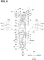
- a front surface of the ink cartridge 30 is a surface appearing in the front view shown in FIG. 8 .
- a rear surface of the ink cartridge 30 is a surface appearing in the rear view shown in FIG. 9 .
- An upper surface of the ink cartridge 30 is a surface appearing in the plan view shown in FIG. 6 .
- a lower surface of the ink cartridge 30 is a surface appearing in the bottom view shown in FIG. 7 .
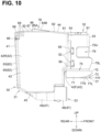
- a left surface of the ink cartridge 30 is a surface appearing in the left side view shown FIG. 10 .
- a right surface of the ink cartridge 30 is a surface appearing in the right side view shown in FIG. 5 .
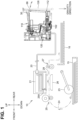
- the printer 10 includes the cartridge case 110, a sub-tank 120, an ink tube 20, a recording head 21, and the ink cartridge 30.
- the printer 10 is an inkjet recording apparatus, for example, an inkjet printer that records an image by ejecting ink droplets from the recording head 21 onto a sheet on the basis of an inkjet recording method.
- the printer 10 includes the cartridge case 110.
- the cartridge case 110 is an example of an attachment unit.
- the ink cartridge 30 is configured to be attached to the cartridge case 110.
- the ink cartridge 30 is an example of an ink container.
- the cartridge case 110 has an opening 112 at its rear end.
- the ink cartridge 30 is configured to be inserted frontward into the case 110 through the opening 112 and to be attached to the case 110 when the ink cartridge 30 reaches the attachment position.
- the ink cartridge 30 is configured to be detached and removed rearward from the case 110 through the opening 112.
- the opening 112 is covered by a cover 126 when the cover 126 is closed and is exposed to the outside of printer 10 when the cover 126 is opened.
- FIG. 1 shows a state in which the ink cartridge 30 is completely attached to the cartridge case 110. That is, FIG. 1 shows the ink cartridge 30 in the attached state.
- the posture of the ink cartridge 30 in the attached state is the usage posture.
- the ink cartridge 30 stores ink that can be used in the printer 10.
- the ink may be a liquid containing a colouring material such as a pigment or a processing liquid not containing a colouring material, but containing an additive for improving the quality of image formed by the colouring material.
- a colouring material such as a pigment or a processing liquid not containing a colouring material, but containing an additive for improving the quality of image formed by the colouring material.
- a head control board included in the recording head 21 selectively applies a driving voltage to a plurality of piezoelectric elements 29A provided corresponding to the plurality of nozzles 29.
- ink is selectively ejected from the nozzles 29. That is, the recording head 21 consumes the ink stored in the ink cartridge 30 attached to the cartridge case 110.
- the printer 10 includes a paper feed tray 15, a paper feed roller 23, a pair of conveyance rollers 25, a platen 26, a pair of discharge rollers 27, and a paper discharge tray 16.
- the sheet feed roller 23 feeds a sheet on the sheet feed tray 15 toward a conveyance path 24.
- the sheet fed to the conveyance path 24 reaches the pair of conveyance rollers 25.
- the pair of conveyance rollers 25 conveys the sheet that has reached the pair of conveyance rollers 25 onto the platen 26.
- the recording head 21 selectively ejects ink onto the sheet passing over the platen 26. Thus, an image is recorded on the sheet.
- the sheet having passed through the platen 26 reaches the pair of discharge rollers 27.
- the pair of discharge rollers 27 discharges the sheet that has reached the pair of discharge rollers 27 to the discharge tray 16 positioned at the most downstream end of the conveyance path 24.
- the cartridge case 110 includes a case body 101 and a supply tube 102.
- the case body 101 has a box shape.
- the case body 101 has an internal space to which the ink cartridge 30 is attached.
- the case body 101 has an end surface 103 that defines a front end in the attachment direction when the ink cartridge 30 is attached to the internal space, a left wall that defines a left end of the internal space, a right wall that defines a right end of the internal space, a lower wall, and a cover wall 171 that covers a pressing plate 134 described later.
- the cover wall 171 includes an upper wall 172 facing upward and a rear wall 173 extending downward from a rear end portion of the upper wall 172.
- the case body 101 has the opening 112 at its rear end. When the user opens the cover 126 to use the printer 10, the opening 112 is exposed.
- the case body 101 has three partition walls 109 in its internal space.
- the three partition walls 109 are arranged at intervals in the left-right direction.
- the internal space of the case body 101 has four slots 108A, 108B, 108C, and 108D arranged in the left-right direction.
- the slot 108A is positioned on the rightmost side among the four slots 108A to 108D.
- the slot 108B is positioned to the left of the slot 108A.
- the slot 108C is positioned to the left of the slot 108B.
- the slot 108D is positioned on the left of the slot 108C and on the leftmost side among the four slots 108A to 108D.
- the internal space of the case body 101 is partitioned into slots 108A, 108B, 108C, and 108D by the three partition walls 109 that partition the internal space of the case body 101 and by the inner surface of the case body 101.
- the partition wall 109 extends upward from the upper surface of the upper wall 172 of the cover wall 171.
- the three partition walls 109 are positioned at equal intervals in the left-right direction.
- the partition wall 109 has a flat plate shape extending in the up-down direction and the front-rear direction.
- the partition wall 109 extends from the front end to the rear end of the upper wall 172.
- the case body 101 has a guide surface 161.
- the guide surface 161 is arranged in each of the slots 108A, 108B, 108C, and 108D.
- the guide surface 161 faces upward.
- the guide surface 161 is generally a semi-circumferential surface.
- a space 162 exists below the supply tube 102.
- the cover wall 171 is positioned below the end surface 103 of the case body 101.
- the upper wall 172 has a flat plate shape extending in the front-rear direction and the left-right direction.
- the upper wall 172 extends from the left wall to the right wall of the case body 101.
- the rear wall 173 has a flat plate shape extending in the up-down direction and the left-right direction.
- the rear wall 173 extends from the left wall to the right wall of the case body 101.
- through holes 144 are positioned at equal intervals in the left-right direction in the respective slots 108A, 108B, 108C, and 108D.
- the guide surface 161 is positioned below the through hole 144, respectively.
- the supply tube 102 passes through the through hole 144 and protrudes rearward from the rear wall 173.
- the upper wall 172 has a groove 113 and a groove 114.
- the groove 113 and the groove 114 in each of the slots 108A, 108B, 108C, and 108D have a common shape.
- the groove 113 is positioned at the left end of each of the slots 108A, 108B, 108C, and 108D
- the groove 114 is positioned at the right end of each of the slots 108A, 108B, 108C, and 108D.
- Both the groove 113 and the groove 114 are recessed downward from the upper wall 172 and extend along the front-rear direction so as to be open in the rear wall 173.
- the ink cartridge 30 includes a pair of walls (described later) and each wall 71 is inserted into the corresponding one of the groove 113 and the groove 114.
- each of the slots 108A, 108B, 108C, and 108D two protruding pieces 117 protruding upward from the upper wall 172 of the cover wall 171 and spaced apart from each other in the left-right direction are provided between the groove 113 and the groove 114 in the left-right direction.
- the upper wall 172 of the cover wall 171 has a through hole 140A that is continuous with a space between the two protruding pieces 117.
- the rear wall 173 of the cover wall 171 has a through hole 140B. The lower end of the through hole 140A and the upper end of the through hole 140B are continuous with each other.
- a first key slot 115 is positioned between the two protruding pieces 117 in each of the slots 108A, 108B, 108C, and 108D.
- the first key slot 115 is an example of a first receiving portion.
- the slot 108A has a first key slot 115A
- the slot 108B has a first key slot 115B
- the slot 108C has a first key slot 115C
- the slot 108D has a first key slot 115D.
- the first key slot 115 opens upward and rearward.
- a first key portion 77 (described later) of the ink cartridge 30 is insertable into the first key slot 115.
- the first key slots 115A, 115B, 115C, and 115D have different positions in the left-right direction with respect to the groove 113 and the groove 114. Specifically, the first key slot 115A is closer to the groove 113 than the center of the slot 108A between the groove 113 and the groove 114 in the left-right direction.
- the first key slot 115B is closer to the groove 114 in the slot 108B than the first key slot 115A is to the groove 114 in the slot 108A in the left-right direction.
- the first key slot 115C is closer to the groove 114 in the slot 108C than the first key slot 115B is to the groove 114 in the slot 108B in the left-right direction.
- the first key slot 115D is closer to the groove 114 in the slot 108D than the first key slot 115C is to the groove 114 in the slot 108C in the left-right direction.
- a rib 118 is positioned above the groove 113 and a rib 119 is positioned above the groove 114.
- the rib 118 protrudes from the inner surface of the right wall 129.
- the rib 118 protrudes from the partition wall 109 defining the right end of the slot 108B.
- the rib 118 protrudes from the partition wall 109 defining the right end of the slot 108C.
- the rib 118 protrudes from the partition wall 109 defining the right end of the slot 108C.
- the rib 118 protrudes from the partition wall 109 defining the right end of the slot 108C.
- the rib 119 protrudes from the partition wall 109 defining the left end of the slot 108A.At the slot 108B, the rib 119 protrudes from the partition wall 109 defining the left end of the slot 108B. At the slot 108C, the rib 119 protrudes from the partition wall 109 defining the left end of the slot 108C. At the slot 108D, the rib 119 protrudes from the inner surface of the left wall 128.
- the ribs 118 and 119 face each other in the left-right direction in each of the slots 108A, 108B, 108C, and 108D.
- the supply tube 102 is positioned in the internal space of each of the slots 108A, 108B, 108C, and 108D.
- the supply tube 102 is positioned below each of the first key slots 115A, 115B, 115C, and 115D.
- the supply tube 102 has a hollow circular pipe shape.
- the supply tube 102 extends along the front-rear direction from a sub-tank 120 toward the internal space of each of the slots 108A, 108B, 108C, and 108D.
- a rear end of the supply tube 102 is opened.
- the rear end of the supply tube 102 is positioned in the inner space of each of the slots 108A, 108B, 108C, and 108D.
- a valve is disposed in the inner space of the supply tube 102.
- the valve opens and closes the opening of the supply tube 102.
- the supply tube 102 is connectable to the supply port 34 of the ink cartridge 30.
- a front end of the supply tube 102 is connected to the sub-tank 120.
- the sub-tank 120 has an internal space that stores the ink supplied from the ink cartridge 30 through the supply tube 102.
- the internal space of the sub-tank 120 communicates with the outside at the upper portion thereof and is open to the atmosphere.
- the ink in the sub-tank 120 is supplied to the recording head 21 through the ink tube 20.
- a rod 121 is positioned above each of the first key slots 115A, 115B, 115C, and 115D.
- the rod 121 protrudes rearward from the end surface 103.
- the rod 121 is connectable to an atmosphere opening passage 38 of the ink cartridge 30, which will be described later.
- a fitting piece 122 and a fitting piece 123 are positioned above each of the first key slots 115A, 115B, 115C, and 115D and below the rod 121.
- the fitting piece 122 is a plate-like member. The fitting piece 122 protrudes leftward from the inner surface of the right wall 129 in the slot 108A.
- the fitting piece 122 protrudes leftward from the partition wall 109 defining the right end of the slot 108B.
- the fitting piece 122 protrudes leftward from the partition wall 109 defining the right end of the slot 108C.
- the fitting piece 122 protrudes leftward from the partition wall 109 defining the right end of the slot 108D.
- the fitting piece 123 is a plate-like member.
- the fitting piece 123 protrudes rightward from the partition wall 109 defining the left end of the slot 108A.
- the fitting piece 123 protrudes rightward from the partition wall 109 defining the left end of the slot 108B.
- the fitting piece 123 protrudes rightward from the partition wall 109 defining the left end of the slot 108C.
- the fitting piece 123 protrudes rightward from the inner surface of the left wall 128 in the slot 108D.
- the fitting piece 122 and the fitting piece 123 face each other in the left-right direction in the slot 108.
- contacts 125 are positioned on the upper inner surface of the case body 101.
- the contacts 125 are electrically connectable to an IC board 60 of the ink cartridge 30.
- a controller of the printer 10 reads information stored in the IC board 60 of the ink cartridge 30 and records information in the IC board 60.
- an ink receiving member 130 is positioned in the space 162 of the case body 101.
- One ink receiving member 130 is provided for each of the slots 108A, 108B, 108C, and 108D.
- the ink receiving member 130 has a front end portion 131 extending in the left-right direction.
- the front end portion 131 is supported by the case body 101.
- the ink receiving member 130 has a substantially flat plate shape extending rearward and upward from the front end portion 131, and a rear end portion 132 of the ink receiving member 130 is positioned in the vicinity of the rear end of the supply tube 102.
- the ink receiving member 130 may rotate about the front end portion 131 so that the rear end portion 132 moves substantially in the up-down direction.
- a coil spring 133 extending along the front-rear direction is positioned between the ink receiving member 130 and the case body 101.
- the coil spring 133 urges, i.e., pulls the rear end portion 132 of the ink receiving member 130 frontward.
- the ink receiving member 130 urged, i.e., pulled by the coil spring 133 is held in a state where the rear end portion 132 is the closest to a lower surface of the supply tube 102. In this state, the rear end portion 132 is not in contact with the lower surface of the supply tube 102.
- the state where the rear end portion 132 of the ink receiving member 130 is the closest to the lower surface of the supply tube 102 is referred to in the following as a closest state of the ink receiving member 130.
- the ink receiving member 130 In the state where the rear end portion 132 of the ink receiving member 130 is the closest to the lower surface of the supply tube 102, the ink receiving member 130 is positioned at a first position. In a state where the ink cartridge 30 is not attached to the supply tube 102, the ink receiving member 130 is in the closest state but not in contact with the lower surface of the supply tube 102.
- ink may remain on the rear end of the supply tube 102.
- Such ink moves to a lower portion of the rear end of the supply tube 102 due to gravity and thereafter drips to the rear end portion 132 of the ink receiving member 130 which is in the closest state to the lower surface of the supply tube 102.
- the received ink moves along the ink receiving member 130 from the rear end portion 132 toward the front end portion 131 away from the ink cartridge 30. Since the ink that remains on the rear end of the supply tube 102 is received by the rear end portion 132 of the ink receiving member 130, it is possible to reduce the possibility that the ink adheres to the lower wall of the case body 101.
- the ink receiving member 130 in a state where the ink receiving member 130 has moved downward against the pulling force of the coil spring 133, the ink receiving member 130 is in a second position.
- a space is provided between the ink receiving member 130 at the second position and the supply tube 102 to such an extent that a lower portion of a supply portion 33 of the ink cartridge 30 can be positioned in the space and the supply tube 102 can be received by the supply portion 33. That is, when the supply tube 102 is received in the supply port 34 of the ink cartridge 30 inserted into each of the slots 108A, 108B, 108C, and 108D in the frontward direction, the ink receiving member 130 does not restrict the frontward movement of the ink cartridge 30.
- the pressing plate 134 is positioned below the cover wall 171 of each of the slots 108A, 108B, 108C, and 108D and in front of the rear wall 173.
- the pressing plate 134 is an example of a moving mechanism.
- the pressing plate 134 is supported by the case body 101 so as to be movable in the up-down direction.
- a lower end 135 of the pressing plate 134 is in contact with the ink receiving member 130 at a portion between the front end portion 131 and the rear end portion 132 of the ink receiving member 130.
- An upper end 136 of the pressing plate 134 is positioned below the first key slot 115 when the ink cartridge 30 is attached to the cartridge case 110 in the attached state.
- the pressing plate 134 is positioned below the through hole 140A of the cover wall 171.
- the pressing plate 134 is positioned in front of the through hole 140B of the rear wall 173. With this configuration, the pressing plate 134 can come into contact with a first key portion 77 of the ink cartridge 30, which will be described later, through the first key slot 115, the through hole 140A, and the through hole 140B.
- the pressing plate 134 is held at a lifted position by the ink receiving member 130 urged, i.e. pulled by the coil spring 133.
- the pressing plate 134 is pressed down by the first key portion 77 against the urging, i.e. pulling force of the coil spring 133.
- the ink receiving member 130 is movable between the first position and the second position.
- second key slots 138 are arranged at positions corresponding to the respective slots 108A, 108B, 108C, and 108D in a surface 137 positioned on the upper side of the peripheral edge of the case body 101, which edge defining the opening 112.
- the slot 108A has a second key slot 138A
- the slot 108B has a second key slot 138B
- the slot 108C has a second key slot 138C
- the slot 108D has a second key slot 138D.
- the second key slot 138 is an example of a second receiving portion.
- the second key slot 138 is a recess formed in a rear end of a top surface of the case body 101 defining an upper end of the internal space of the case body 101.
- the second key slot 138 is recessed upward from the top surface.
- the lower end of the second key slot 138 is continuous with the internal space of the case body 101.
- a rear end of the second key slot 138 is open toward the outside of the case body 101.
- a distance between a lower end and an upper end of the opening at the rear end of the second key slot 138 is greater than a distance between a lower end and an upper end of the opening at the front end of the second key slot 138.
- a distance between the lower end and the upper end of the opening of the second key slot 138 gradually decreases from the rear end of the opening toward the front end of the opening.
- the distance between the lower end and the upper end of the opening of the second key slot 138 may gradually increase and then gradually decrease from the rear end of the opening toward the front end of the opening.
- the second key slots 138A, 138B, and 138C are respectively positioned to the left of the center of the slots 108A, 108B, and 108C in the left-right direction.
- the second key slot 138D is positioned to the right of the center of the slot 108D in the left-right direction.
- a second key portion 78 of the ink cartridge 30 may enter in at least one of the second key slots 138A, 138B, 138C, and 138D.
- a locking portion 139 is positioned in a space that defines the opening of each of the second key slots 138A, 138B, 138C, and 138D.
- the locking portion 139 is a rod-shaped member extending in the left-right direction. The locking portion 139 comes into contact with a locking surface 87 of the ink cartridge 30 when the ink cartridge 30 is attached to the cartridge case 110 in the attached state.
- the ink cartridge 30 is a container in which ink as a liquid is stored. As shown in FIGS. 3 to 10 , the ink cartridge 30 includes a container body 31, a cover 32, and an IC board 60.
- the container body 31 is an example of a first member.
- the cover 32 is an example of a second member.
- the container body 31 and the cover 32 are an example of a main body.
- the cover 32 covers a front portion of the container body 31.
- the ink cartridge 30 is inserted frontward into a corresponding one of the slots 108A, 108B, 108C, and 108D with the cover 32 facing the end surface 103 of the case body 101.
- the container body 31 has a substantially thin flat cubic shape in which the length in the left-right direction is smaller than the length in the up-down direction and the length in the front-rear direction.
- the container body 31 includes a supply portion 33, a first key portion 77, and a second key portion 78.
- the container body 31 includes a front wall 40, a rear wall 41 opposed to the front wall 40 in the front-rear direction, a left wall 42 connecting the front wall 40 and the rear wall 41, a right wall 43 opposed to the left wall 42 in the left-right direction, an upper wall 44 connecting the front wall 40 and the rear wall 41, and a lower wall 45 opposed to the upper wall 44 in the up-down direction.
- the container body 31 has an upper surface 80 which is an outer surface of the upper wall 44.
- the outer surface of the front wall 40 faces frontward.
- the rear wall 41 has a rear surface 62 facing rearward.
- the outer surface of the left wall 42 faces leftward.
- the outer surface of the right wall 43 faces rightward.
- the outer surface of the upper wall 44, i.e., the upper surface 80 faces upward.
- the outer surface of the lower wall 45 faces downward.
- the front wall 40, the rear wall 41, the left wall 42, the right wall 43, the upper wall 44, and the lower wall 45 define a chamber 46 in the internal space of the container body 31.
- the front wall 40, the rear wall 41, the left wall 42, the right wall 43, the upper wall 44, and the lower wall 45 have translucency to the extent that the liquid level of the ink stored in the chamber 46 can be visually recognized from the outside.
- the container body 31 is, for example, an integrally molded product made of a synthetic resin.
- the front wall 40 has an upper front wall 40U positioned on the upper side and a lower front wall 40L positioned on the lower side.
- the upper front wall 40U is positioned frontward of the lower front wall 40L in the front-rear direction.
- a space behind the upper front wall 40U in the front-rear direction is also a part of the chamber 46.
- the upper portion of the chamber 46 extends further frontward than the lower portion of the chamber 46.
- the lower front wall 40L is continuous with the supply portion 33.
- the left wall 42 includes a front left wall 42F positioned on the front side in the front-rear direction and a rear left wall 42R positioned on the rear side in the front-rear direction.
- the right wall 43 includes a front right wall 43F positioned on the front side in the front-rear direction and a rear right wall 43R positioned on the rear side in the front-rear direction.
- the front left wall 42F and the front right wall 43F are continuous with the upper front wall 40U.
- the rear left wall 42R and the rear right wall 43R are continuous with the rear wall 41.
- a space between the front left wall 42F and the front right wall 43F is a part of the chamber 46.
- a distance in the left-right direction between an outer surface of the front left wall 42F and an outer surface of the front right wall 43F is smaller than a distance in the left-right direction between an outer surface of the rear left wall 42R and an outer surface of the rear right wall 43R.
- Two protrusions 52 are positioned on the front left wall 42F. Two protrusions 52 are positioned on the front right wall 43F. On the front left wall 42F, the two protrusions 52 are separated from each other in the up-down direction. On the front right wall 43F, the two protrusions 52 are separated from each other in the up-down direction.
- the protrusion 52 has a substantially rectangular shape in a side view. The protrusion 52 passes through a through hole 76 of the cover 32 described later.
- the supply portion 33 is a cylindrical member.
- the supply portion 33 has an outer peripheral surface extending in the front-rear direction.
- the outer peripheral surface is a curved surface curved in a circumferential direction with the front-rear direction as an axis.
- the supply portion 33 is positioned at a lower end of the container body 31, and a part of an outer surface of the supply portion 33 constitutes a lower surface 47 of the container body 31.
- the supply portion 33 has a supply port 34 through which the ink flows out of the ink cartridge 30.
- the supply port 34 is positioned at the front end of the supply portion 33.
- the supply port 34 is circular when viewed from the front.
- the lower surface 47 includes a lower half of a circumferential surface having an axis in the front-rear direction.
- the lower surface 47 includes a first surface 48 having a cylindrical shape in the front-rear direction and a second surface 49 positioned rearward of the first surface 48 in the front-rear direction.
- the outer diameter of the supply portion 33 decreases from the first surface 48 toward the second surface 49.
- the supply portion 33 has a cylindrical shape and has an internal space.
- the internal space of the supply portion 33 communicates with the chamber 46 at the rear in the front-rear direction. Ink in the internal space of the supply portion 33 can flow out to the outside of the ink cartridge 30 through the supply port 34.
- a seal member 35, a valve 36, and a coil spring 37 are positioned in the internal space of the supply portion 33.
- the seal member 35 is an annular member made of an elastic member, for example, rubber or the like, and is positioned in the supply port 34 and in the internal space of the supply portion 33.
- the supply port 34 is filled with the seal member 35, but ink in the internal space of the supply portion 33 can flow out to the outside of the ink cartridge 30 through a hole formed through the center of the seal member 35 in the front-rear direction, that is, ink in the internal space of the supply portion 33 still can flow out to the outside of the ink cartridge 30 through the supply port 34.
- the valve 36 is movable in the front-rear direction in the internal space of the supply portion 33.
- the hole formed through the seal member 35 is closed or sealed, in other words, the supply port 34 is closed or sealed. That is, ink in the internal space of the supply portion 33 cannot flow out to the outside of the ink cartridge 30 through the hole formed through the seal member 35, in other words, cannot flow out to the outside of the ink cartridge 30 through the supply port 34.
- the coil spring 37 biases the valve 36 toward the seal member 35 so that the valve 36 contacts the seal member 35.
- the supply tube 102 When the ink cartridge 30 is inserted into the cartridge case 110, the supply tube 102 enters the supply port 34. The outer circumferential surface of the supply tube 102 comes into contact with the inner circumferential surface, which is defined by the hole of the seal member 35, in a liquid-tight manner while the supply tube 102 elastically deforms the sealing member 35. When the rear end of the supply tube 102 passes through the sealing member 35 and enters the internal space of the supply portion 33, the rear end of the supply tube 102 comes into contact with the valve 36. When the ink cartridge 30 is further inserted into the cartridge case 110, the ink tube 102 pushes the valve 36 to move in the rearward direction against the biasing force of the coil spring 37.
- the seal member 35 is in contact with the outer circumferential surface of the supply tube 102 so as not to leak the ink.
- the valve 36 which closes or seal the supply port 34 and the coil spring 37, are not necessarily provided.
- the supply port 34 may be blocked with a film or the like, and when the ink cartridge 30 is inserted into the cartridge case 110, the supply tube 102 breaks the film and the rear end of the supply tube 102 thereby enters the internal space of the supply portion 33 through the supply port 34.
- the hole of the seal member 35 positioned in the supply port 34 may be closed due to the elasticity of the seal member 35 itself, and when the supply tube 102 is inserted, the hole is expanded by being pressed by the supply tube 102 and the rear end of the supply tube 102 thereby enters the internal space of the supply portion 33 through the supply port 34.
- ink in the internal space of the supply portion 33 flows out to the outside of the ink cartridge 30 through the supply tube 102 positioned in the supply port 34, in other words, through the supply port 34.
- a convex portion 59 protruding downward is positioned on the first surface 48 of the supply portion 33.
- an outline of a portion where the convex portion 59 is continuous with the first surface 48 has a substantially square shape when viewed upward from below in the up-down direction, and a length of the outline in the front-rear direction is substantially equal to a length of the outline in the left-right direction.
- Both side surfaces of the convex portion 59 in the left-right direction are downward triangles.
- Each side surface of the convex portion 59 in the left-right direction is a tapered surface that is inclined toward the center of the convex portion 59 in the left-right direction as the side surface extends downward.
- the convex portion 59 has a tapered shape in which the length in the left-right direction gradually decreases as the side surface extends downward.
- an atmosphere opening passage 38 that connects the vicinity of the upper end of the chamber 46 and is connectable to the outside of the ink cartridge 30 is positioned at the upper front wall 40U of the container body 31.
- the atmosphere opening passage 38 opens frontward at the upper front wall 40U.
- a valve 50 and a coil spring 51 are positioned in the atmosphere opening passage 38.
- the coil spring 51 is an example of a biasing member.
- a front end of the coil spring 51 is positioned above and frontward of the supply port 34 of the supply portion 33.
- the front end of the coil spring 51 is positioned frontward of the second key portion 78.
- the valve 50 is movable in the front-rear direction in the atmosphere opening passage 38.
- the coil spring 51 biases the valve 50 frontward.
- the valve 50 urged by the coil spring 51 seals the opening of the atmosphere opening passage 38.
- the atmosphere opening passage 38 is opened to allow air to flow between the outside of the ink cartridge 30 and the chamber 46.
- the cover 32 has a substantially rectangular parallelepiped shape whose length in the left-right direction is smaller than a length in the up-down direction and a length in the front-rear direction of the container body 31.
- the cover 32 has a box shape having an opening facing rearward.
- the cover 32 is attached to the container body 31 so as to substantially cover the upper front wall 40U, the front left wall 42F, and the front right wall 43F.
- the cover 32 includes a front wall 53, a left wall 54 extending rearward from a left end of the front wall 53, a right wall 55 opposed to the left wall 54 in the left-right direction, an upper wall 56 extending rearward from an upper end of the front wall 53, and a lower wall 57 opposed to the upper wall 56 in the up-down direction.
- the front wall 53, the left wall 54, the right wall 55, the upper wall 56, and the lower wall 57 define an internal space of the cover 32.
- the opening of the cover 32 is defined by rear ends of the front wall 53, the left wall 54, the right wall 55, the upper wall 56, and the lower wall 57.
- the front wall 53 is a part of the front wall of the ink cartridge 30.
- the left wall 54 is a part of a left wall of the ink cartridge 30.
- the right wall 55 is a part of the right wall of the ink cartridge 30.
- the upper wall 56 is a part of an upper wall of the ink cartridge 30.
- the lower wall 57 is a part of a lower wall of the ink cartridge 30.
- the length of the cover 32 in the up-down direction is smaller than the length of the container body 31 in the up-down direction.
- the length of the cover 32 in the front-rear direction is smaller than the length of the container body 31 in the front-rear direction.
- the distance of the cover 32 in the left-right direction is slightly greater than the distance between the outer surface of the front left wall 42F and the outer surface of the front right wall 43F of the container body 31 in the left-right direction, and is substantially the same as the distance between the outer surface of the rear left wall 42R and the outer surface of the rear right wall 43R in the left-right direction.
- the left wall 54 has two through holes 58 spaced apart in the up-down direction.
- the right wall 55 has two through holes 58 spaced apart in the up-down direction.
- the protrusions 52 on the front left wall 42F are positioned in the through holes 58 of the left wall 54, and the protrusions 52 on the front right wall 43F are positioned in the through holes 58 of the right wall 55.
- the through hole 58 has a substantially rectangular shape. Specifically, the length of each through hole 58 in the up-down direction is greater than the length thereof in the front-rear direction.
- the through hole 58 is sufficiently larger than the outer shape of the protrusion 52.
- each through hole 58 in the up-down direction is greater than the length of each protrusion 52 in the up-down direction.
- the length of each through hole 58 in the front-rear direction is greater than the length of each protrusion 52 in the front-rear direction.
- the container body 31 and the cover 32 are assembled by inserting the protrusions 52 into the corresponding through holes 58. Since the through hole 58 is larger than the outer shape of the protrusion 52, the cover 32 is relatively movable in the up-down direction and the front-rear direction with respect to the container body 31 in a state where the container body 31 and the cover 32 are assembled. Since the through hole 58 is sufficiently larger than the outer shape of the protrusion 52, the cover 32 can move relative to the container body 31 not only in the up-down direction and the front-rear direction, but also in a direction in which the cover 32 rotates relative to the container body 31 along a plane extending in the up-down direction and the front-rear direction.
- the cover 32 covers the upper front wall 40U of the container body 31 in the state in which the cover 32 is attached to the container body 31.
- the front wall 53 of the cover 32 is positioned frontward of the supply port 34.
- the supply port 34 is positioned below the lower wall 57 of the cover 32.
- the IC board 60 is positioned on the upper wall 56 of the cover 32.
- the IC board 60 is an example of an electrical interface.
- the IC board 60 extends in the front-rear direction and the left-right direction.
- the IC board 60 is positioned above the supply port 34.
- the IC board 60 includes a substrate formed of, for example, silicone or glass epoxy, an IC mounted on the substrate and three electrodes 61 mounted on the substrate. Note that the IC does not appear in the drawings.
- the IC board 60 may comprise a flexible substrate having flexibility.
- the upper surface of the electrode 61 is an example of a contact surface.
- the IC board 60 is bonded to the upper wall 56 of the cover 32 by, for example, a photocurable resin.
- the IC board 60 may be bonded to the cover 32 by an adhesive other than the photocurable resin, or may be attached to the cover 32 by fitting or the like other than bonding.
- the electrodes 61 of the IC board 60 come into contact with the contacts 125 in the process in which the ink cartridge 30 is inserted into the cartridge case 110. In the attached state where the ink cartridge 30 is attached to the cartridge case 110, the IC board 60 is in contact with and electrically connected to the contacts 125.
- the IC is a semiconductor integrated circuit.
- Information related to the ink cartridge 30 is readably stored in the IC.
- the information related to the ink cartridge 30 is, for example, data indicating information such as a lot number, a manufacturing date, and an ink colour.
- the electrode 61 is electrically connected to the IC.
- the electrode 61 extends in the front-rear direction.
- the electrodes 61 are arranged on the upper surface of the IC board 60 so as to be spaced apart from each other in the left-right direction.
- the electrode 61 is exposed on the upper surface of the IC board 60 so as to be electrically accessible.
- the upper wall 56 of the cover 32 has a through hole 90 in front of the IC board 60.
- the atmosphere opening passage 38 is positioned below the through hole 90.
- Guide pieces 91 extending in the front-rear direction protrude upward near both ends of the upper wall 56 of the cover 32 in the left-right direction.
- the IC board 60 is positioned between the one guide piece 91 and the other guide piece 91 in the left-right direction.
- the guide piece 91 functions as a guide for the cover 32 to move along the front-rear direction when the cover 32 is inserted into the cartridge case 110.
- a lower surface 70 which is an outer surface of the lower wall 57 of the cover 32 is positioned above and frontward of the supply port 34.
- the lower surface 70 is a flat surface extending rearward from the lower end of the front wall 53, and is inclined so as to extend downward toward the rear.
- the cover 32 has walls 71 extending downward from both ends of the lower surface 70 in the left-right direction.
- the one wall 71 and the other wall 71 are spaced apart from each other in the left-right direction.
- the one wall 71 and the other wall 71 are examples of a first wall and a second wall.
- the wall 71 is a plate-like member extending in the up-down direction and the front-rear direction and having a thickness in the left-right direction.
- the length of the wall 71 in the front-rear direction is greater than the length of the wall 71 in the left-right direction and the length of the wall 71 in the up-down direction.
- the length of the wall 71 in the up-down direction is greater than the length thereof in the left-right direction.
- the front surface of the wall 71 has a first front surface 72 positioned at an upper portion thereof and a second front surface 73 positioned at a lower portion thereof.
- a front end of the first front surface 72 is inclined so as to extend upward as the front end of the first front surface 72 extends toward the rear.
- the second front surface 73 is inclined so as to extend downward as the front end of the second front surface 73 extends toward the rear.
- the rear ends of the two walls 71 contact with a sub-front wall 88 (also referred to as a wall), and the two walls 71 extend frontward from the sub-front wall 88.
- the sub-front wall 88 extends downward from the rear end of the lower surface 70.
- the sub-front wall 88 has a plate shape extending in the up-down direction and the left-right direction and having a thickness in the front-rear direction.
- the length of the sub-front wall 88 in the left-right direction is greater than the length thereof in the up-down direction.
- the outer surface of the sub-front wall 88 facing frontward is a part of the front surface of the cover 32.
- a groove 74 (also referred to as a first groove 74) extending in the front-rear direction is positioned above the wall 71.
- the first groove 74 is positioned leftward and upward of the first key portion 77 and extends in the front-rear direction.
- a groove 74 (also referred to as a second groove 74) extending in the front-rear direction is positioned above the wall 71.
- the second groove 74 is positioned rightward and upward of the first key portion 77 and extends in the front-rear direction.
- a longitudinal direction of the groove 74 is the front-rear direction.
- the groove 74 is defined by a surface 74L facing upward, a surface 74U facing the surface 74L in the up-down direction, and a surface 74M connecting the surface 74L and the surface 74U.
- the front end of the groove 74 is open frontward in the front wall 53 of the cover 32. That is, the first groove 74 has an opening at a front end and a left end, and the second groove has an opening at a front end and a right end.
- the first front surface 72 of the one wall 71 serves as a guide for guiding the rib 118 of the cartridge case 110 into the one groove 74.
- the first front surface 72 of the other wall 71 serves as a guide for guiding the rib 119 of the cartridge case 110 into the first groove 74.
- One of the grooves 74 has a length capable of receiving the rib 118 of the case body 101 in the front-rear direction
- the other groove 74 has a length capable of receiving the rib 119 of the case body 101 in the front-rear direction.
- the distance between the surface 74L and the surface 74U of the groove 74 in the up-down direction is greater than each of the lengths of the rib 118 and the rib 119 of the case body 101 in the up-down direction.
- the position of the cover 32 with respect to the case body 101 in the up-down direction is determined by the contact of the surface 74U and the surface 74L of one of the grooves 74 with the rib 118 and by the contact of the surface 74U and the surface 74L of one of the grooves 74 with the rib 119.
- the outer surface of the front wall 53 of the cover 32 is a front surface 75.
- the front surface 75 is positioned frontward of the supply port 34.
- the front surface 75 has an upper front surface 75U positioned at an upper portion thereof and a lower front surface 75L positioned at a lower portion thereof.
- the upper end of the lower front surface 75L is continuous with the upper front surface 75U.
- the lower end of the lower front surface 75L is positioned rearward of the upper end of the lower front surface 75L, and the lower front surface 75L is inclined upward as the lower front surface 75L extends toward the front.
- the lower front surface 75L is a guide for guiding the rib 118 and the rib 119 into the groove 74. Specifically, in the process in which the ink cartridge 30 is inserted into the case 110, the lower front surface 75L comes into contact with the front end of the rib 118 and the front end of the rib 119. In this configuration, the lower front surface 75L guides each of the rib 118 and the rib 119 to the groove 74.
- the upper front surface 75U of the front wall 53 of the cover 32 has a through hole 76.
- the valve 50 of the container body 31 is exposed to the outside through the through hole 76.
- the front end of the through hole 76 is positioned frontward of the supply port 34 of the supply portion 33.
- the lower surface 70 of the cover 32 has a first key portion 77.
- the first key portion 77 is positioned above the supply port 34 and below the upper surface of the electrode 61 of the IC board 60.
- the front end of the first key portion 77 is positioned frontward of the front end of the electrode 61.
- the first key portion 77 is positioned below the through hole 76.
- the opening of the atmosphere opening passage 38 is positioned between the first key portion 77 and the electrode 61 in the up-down direction.
- the first key portion 77 is positioned at a front part of the ink cartridge 30.
- the first key portion 77 is positioned between the pair of walls 71 in the left-right direction and extends downward from the lower surface 70.
- a rear end of the wall 71 is continuous with the sub-front wall 88.
- a rear end of the first key portion 77 is continuous with the sub-front wall 88.
- the first key portion 77 has a lower surface 77L defining a lower end of the first key portion 77, side surfaces 77S, and a front surface 77F defining a front end of the first key portion 77.
- the side surfaces 77S of the first key portion 77 include a surface facing leftward and a surface facing rightward.
- Each of the side surfaces 77S of the first key portion 77 extends along the up-down direction and the front-rear direction.
- the lower surface 77L of the first key portion 77 extends along the front-rear direction and left-right direction.
- the lower surface 77L defines the width of the first key portion 77 in the left-right direction.
- the first key portion 77 has a plate shape in which the length in the front-rear direction is greater than the length in each of the left-right direction and the length in the up-down direction, however the shape of the first key portion 77 is not limited thereto.
- the length of the first key portion 77 in the front-rear direction may be smaller than the length thereof in the up-down direction.
- the lower surface 77L is a position overlapping at least one of the electrodes 61 in the up-down direction. In other words, the lower surface 77L is positioned directly below at least one of the electrodes 61 in the up-down direction.
- the length L1 of the lower surfaces 77L in the front-rear direction is greater than the length L2 of the upper surface of the electrodes 61 in the front-rear direction.
- the front surface 77F of the first key portion 77 faces frontward.
- the front surface 77F is positioned rearward of the front end of the first front surface 72 of the wall 71.
- the first front surface 72 is positioned rearward of the front end of the second front surface 73.
- the front surface 77F of the first key portion 77 is positioned rearward of the front end of the front wall 53 of the cover 32.
- the front surface 77F of the first key portion 77 does not collide with the floor or the like. Therefore, the first key portion 77 is less likely to be deformed by a direct impact.
- the firs key portion 77 functions as a key to ensure that the ink cartridge 30 is attached to the right slot 108. When the first key portion 77 is deformed, the first key portion 77 may not correctly function as a key.
- the position of the first key portion 77 (77A, 77B, 77C, and 77D) in the left-right direction is different among the four ink cartridges 30 (30A, 30B, 30C, and 30D).
- This difference in the position of the first key portions 77 (77A, 77B, 77C, and 77D) corresponds to the difference in the position of the first key slots 115 (115A, 115B, 115C, and 115D) in the slots 108 (108A, 108B, 108C, and 108D).
- the position of the first key portion 77 (77A, 77B, 77C, and 77D) in the left-right direction is different among the four ink cartridges 30 (30A, 30B, 30C, and 30D).
- the position of the first key portion 77(77A, 77B, 77C, and 77D) in the left-right direction may be the same among the four ink cartridges 30 (30A, 30B, 30C, and 30D), but the shape of the first key portion 77(77A, 77B, 77C, and 77D) may be different among the four ink cartridges 30 (30A, 30B, 30C, and 30D).
- the position of the first key slots 115 (115A, 115B, 115C, and 115D) in the slots 108 (108A, 108B, 108C, and 108D) may be the same, but the shape of the first key slots 115 (115A, 115B, 115C, and 115D) in the slots 108 (108A, 108B, 108C, and 108D) may be different corresponding to the difference in shape of the first key portions 77 (77A, 77B, 77C, and 77D).
- the mechanical characteristic, e.g., position or shape, of the first key portion 77(77A, 77B, 77C, and 77D) is different among the four ink cartridges 30 (30A, 30B, 30C, and 30D).
- the mechanical characteristic of the first key portion 77 corresponds to the corresponding one of the ink cartridges 30 (30A, 30B, 30C, and 30D). That is, the first key portion 77 has a shape and/or position at the container body 31 which is associated with a corresponding first characteristic of the ink cartridge 30.
- the characteristic of the ink cartridge 30 is the characteristic of the ink stored in the chamber 46.
- the position of the first key portion 77 in the left-right direction is different among the four ink cartridges 30 (30A, 30B, 30C, and 30D) depending on the characteristic of the ink stored in the chamber 46
- the characteristic of the ink is, for example, the colour or composition of the ink.
- the cover 32 includes a third key portion 79.
- the third key portion 79 is defined by a recessed portion recessed from the left wall 54 of the cover 32, a recessed portion recessed from the right wall 55, a convex portion protruding leftward from the left wall 54, or a convex portion protruding rightward from the right wall 55.
- the third key portion 79 includes a recessed portion that is recessed from the left wall 54 of the cover 32 and a recessed portion that is recessed from the right wall 55.
- the third key portion 79 is a combination of the recessed portion of the left wall 54 and the recessed portion of the right wall 55.
- the third key portion 79 is positioned above the first key portion 77 and below the upper surface of the electrode 61 of the IC board 60.
- the third key portion 79 is positioned below the through hole 76
- the third key portion 79 is positioned at both ends of the upper front surface 75U in the left-right direction.
- the front end of the third key portion 79 is opened frontward in the upper front surface 75U of the cover 32. That is, both of the recessed portion of the left wall 54 and the recessed portion of the right wall 55 are opened frontward in the upper front surface 75U of the cover 32.
- the mechanical characteristic such as the position and/or shape of the third key portion 79 is different.
- the characteristic of the ink cartridge 30 indicated by the third key portion 79 may be the same as or different from the characteristic of the ink cartridge 30 indicated by the first key portion 77.
- the characteristic of the ink cartridge 30 indicated by the first key portion 77 is the colour of the ink
- the characteristic of the ink cartridge 30 indicated by the third key portion 79 is the type of contract that a user will enter into when using a printer in which the ink cartridge 30 is used.
- the type of contract may include a contract in which a user is charged in accordance with the number of pages on which image recording is performed regardless of the amount of ink used.
- the characteristic of the ink cartridge 30 indicated by the third key portion 79 is a sales area of the printer in which the ink cartridge 30 is used.
- the shape of the third key portion 79 of the ink cartridge 30 used in a certain sales area is different from the shape of the third key portion 79 of the ink cartridge 30 used in another sales area.
- the third key portion 79 may be disposed only on one of the left and right sides, or the shape of the third key portion 79 opening frontward may be different depending on the contract type or the sales area.
- the third key portions 79 including the recessed portion on the left wall 54 of the cover 32 and the recessed portion on the right wall 55 matches with the fitting piece 123 and the fitting piece 122, respectively.
- the presence or absence and the shape of each of the fitting piece 123 and the fitting piece 122 may change depending on the presence or absence and the shape of the corresponding third key portion 79.
- the container body 31 has a rear surface 62 as an outer surface of the rear wall 41 of the container body 31.
- the rear surface 62 includes a first rear surface 63, a second rear surface 64, and a third rear surface 65.
- the second rear surface 64 is positioned on the left of the first rear surface 63.
- the third rear surface 65 is positioned on the right of the first rear surface 63.
- the first rear surface 63 is a flat surface orthogonal to the front-rear direction.
- the second rear surface 64 is a plane intersecting with the front-rear direction and the right-left direction.
- the right end of the second rear surface 64 is continuous with the first rear surface 63.
- the left end of the second rear surface 64 is positioned leftward and rearward of the first rear surface 63.
- the third rear surface 65 is a plane intersecting with the front-rear direction and the left-right direction.
- the left end of the third rear surface 65 is continuous with the first rear surface 63.
- the right end of the third rear surface 65 is positioned rightward and rearward of the first rear surface 63.
- the length of the first rear surface 63 in the left-right direction is constant in the up-down direction.
- the lower wall 45 of the container body 31 includes a first lower wall 45A and a second lower wall 45B.
- a rear end of the first lower wall 45A is continuous with a lower end of the rear wall 41.
- a front portion of the first lower wall 45A extends in the front-rear direction.
- a front end of the first lower wall 45A is continuous with the front wall 40.
- the supply portion 33 is positioned on the first lower wall 45A.
- the curved front surface of the supply portion 33 including the rear end of the supply portion 33 protrudes downward from the first lower wall 45A.
- the second lower wall 45B is continuous with the lower end of the rear wall 41.
- the second lower wall 45B is an inclined wall inclined with respect to the front-rear direction.
- the second lower wall 45B is inclined with respect to the front-rear direction and the up-down direction such that an upper end of the second lower wall 45B is positioned rearward and upward of a lower end thereof.
- the lower end of the second lower wall 45B is continuous with the rear end of the lower surface 47 of the supply portion 33.
- the lower end of the second lower wall 45B is continuous with the rear end of the supply portion 33 in a position below the first lower wall 45A.
- the second lower wall 45B is shorter than the first lower wall 45A in the left-right direction.
- the supply portion 33 is positioned below the first lower wall 45A, as shown in FIG. 9 , the lower surface 47 of the supply portion 33 is visible when the ink cartridge 30 is viewed from the rear. Therefore, it is possible for the user to recognize where the supply portion 33 is when viewed from the rear, and it is easy to attach the ink cartridge 30 in the correct orientation when the ink cartridge 30 is attached to the slot 108.
- the lower wall 45 is continuous with the rear end of the supply portion 33, the rear end of the supply portion 33 is reinforced. As a result, even if the lower end of the ink cartridge 30 receives an impact, the supply portion 33 is less likely to be deformed.
- the lower wall 45 may have only the first lower wall 45A without the second lower wall 45B.
- the second rear surface 64 has a recess 66 near the upper end.
- the recess 66 is constituted by a space recessed frontward from the second rear surface 64 and a surface defining the space.
- the third rear surface 65 has a recess 67 near the upper end.
- the recess 67 is constituted by a space recessed frontward from the third rear surface 65 and a surface defining the space.
- a protrusion 127 protruding from the cover 126 is accommodated in each of the recesses 66 and 67 when the cover 126 is closed.
- the protrusion 127 of the cover 126 in the closed state is in contact with the surface forming the upper end of the recesses 66 and 67.
- a length in the left-right direction of the first rear surface 63 sandwiched between the recess 66 and the recess 67 is greater than a length in the left-right direction of the recess 66 and greater than a length in the left-right direction of the recess 67.
- the rear end of the upper surface 80 of the upper wall 44 of the container body 31 includes an operation surface 68.
- the operation surface 68 is an inclined surface inclined so as to face upward and rearward.
- the operation surface 68 is continuous with the upper end of the rear surface 62.
- the operation surface 68 has a plurality of protrusions 69 that protrude upward and extend along the left-right direction.
- the protrusion 69 is an example of an anti-slip structure.
- the protrusions 69 extend downward from both ends of the operation surface 68 in the left-right direction so as to reach the outer surfaces of the left wall 42 and the right wall 43.
- Three protrusions 69 extend from the left end of the operation surface 68 to the left wall 42 so as to be spaced apart in the front-rear direction.
- Three protrusions 69 extend from the right end of the operation surface 68 to the right wall 43 so as to be spaced apart in the front-rear direction.
- the protrusions 69 function as a slip stopper when the user operates the operation surface 68.
- slip stopper may be, for example, a recess recessed downward from the operation surface 68 instead of the protrusion 69.
- the upper surface 80 of the container body 31 includes a first upper surface 81, a second upper surface 82, a third upper surface 83, an upper end surface 86, and the operation surface 68.
- the first upper surface 81 is positioned at a front end of the upper surface 80.
- the first upper surface 81 has a surface 81A positioned at the center in the left-right direction, a surface 81B positioned on the left, and a surface 81C positioned on the right.
- the surface 81A is a plane orthogonal to the up-down direction.
- the surface 81B is continuous with the left end of the surface 81A.
- the surface 81C is continuous with the right end of the surface 81A.
- the surface 81B is a surface facing upward and leftward.
- the surface 81C is a surface facing upward and rightward.
- the length of the surface 81A in the left-right direction is smaller than the length of the surface 81B in the left-right direction.
- the length of the surface 81A in the left-right direction is smaller than the length of the surface 81C in the left-right direction.
- the second upper surface 82 is continuous with the rear end of the first upper surface 81.
- the rear end of the second upper surface 82 is positioned higher than the front end thereof.
- the second upper surface 82 has a surface 82A positioned at the center in the left-right direction, a surface 82B positioned on the left of the surface 82A, and a surface 82C positioned on the right of the surface 82A.
- the surface 82A is inclined with respect to the front-rear direction so as to face frontward and upward.
- the surface 82A is a flat surface extending in the front-rear direction and the left-right direction.
- the surface 82A faces upward and frontward.
- the surface 82B is continuous with the left end of the surface 82A and faces leftward.
- the surface 82C is continuous with the right end of the surface 82A and faces rightward.
- the length of the surface 82A in the left-right direction is smaller than the length of the surface 82B in the left-right direction.
- the length of the surface 82A in the left-right direction is smaller than the length of the surface 82C in the left-right direction.
- the length of the surface 82A in the left-right direction is equal to the length of the surface 81A in the left-right direction.
- the length of the surface 82A in the front-rear direction is greater than the length of the surface 81A in the front-rear direction.
- the third upper surface 83 is continuous with the rear end of the surface 82C of the second upper surface 82.
- the third upper surface 83 is a plane orthogonal to the up-down direction.
- the third upper surface 83 is positioned above the first upper surface 81.
- a rear end of the third upper surface 83 is continuous with the operation surface 68.
- the third upper surface 83 has a contact surface 92.
- the contact surface 92 extends rearward from a lower end of a locking surface 87 of a second key portion 78 described later.
- the second key portion 78 is positioned on the third upper surface 83 of the container body 31.
- the second key portion 78 protrudes upward from the third upper surface 83.
- the second key portion 78 is positioned above the supply port 34.
- An upper end of the second key portion 78 is positioned above the upper surface of the electrode 61 of the IC board 60.
- the second key portion 78 is positioned rearward of the IC board 60 in the front-rear direction.
- the second key portion 78 is positioned frontward of the operation surface 68.
- the cover 32 When the protrusion 52 of the container body 31 is in contact with the upper end of the through hole 58 of the cover 32, the cover 32 is positioned at the lowest position with respect to the container body 31. In a state where the cover 32 is positioned at the lowest position with respect to the container body 31, the upper end of the second key portion 78 is positioned above the IC board 60.
- the second key portion 78 has a first frontward inclined surface 84A, a second frontward inclined surface 84B, a left inclined surface 85A, a right inclined surface 85B, an upper end surface 86, and a locking surface 87.
- the first frontward inclined surface 84A is a flat surface and is inclined such that a distance with regard to the supply port 34 in the up-down direction gradually increases from a front end of the second key portion 78 toward a rear end of the second key portion 78.
- the first frontward inclined surface 84A is continuous with the rear end of the surface 82B of the second upper surface 82.
- the second frontward inclined surface 84B is a flat surface inclined with respect to the front-rear direction so as to face upward and frontward.
- the second frontward inclined surface 84B extends leftward as the second frontward inclined surface 84B extends rearward from the front end thereof.
- the rear end of the second frontward inclined surface 84B is continuous with the upper end surface 86.
- the front end of the second frontward inclined surface 84B is continuous with the rear end of the surface 82A of the second upper surface 82.
- the lower end of the second frontward inclined surface 84B is continuous with the third upper surface 83.
- the left end of the second frontward inclined surface 84B is continuous with the right end of the first frontward inclined surface 84A.
- a boundary between the first frontward inclined surface 84A and the second frontward inclined surface 84B extends leftward from the front end toward the rear.
- An upper end of the boundary between the first frontward inclined surface 84A and the second frontward inclined surface 84B is continuous with the upper end surface 86.
- the upper end surface 86 is a flat surface facing upward.
- An upper end of the locking surface 87 is continuous with a rear end of the upper end surface 86.
- the upper end surface 86 is positioned between the second frontward inclined surface 84B and the locking surface 87 in the front-rear direction.
- the locking surface 87 is a flat surface facing rearward. In the attached state where the ink cartridge 30 is attached to the cartridge case 110, the locking surface 87 and the contact surface 92 are in contact with the locking portion 139 of the cartridge case 110.
- the left inclined surface 85A is a flat surface inclined with respect to the left-right direction so as to extend upward from the left end toward the right end.
- the left inclined surface 85A is continuous with a left end of the first frontward inclined surface 84A.
- a boundary between the left inclined surface 85A and the first frontward inclined surface 84A extends rightward from the front end toward the rear end.
- a rear end of the boundary between the left inclined surface 85A and the first frontward inclined surface 84A is continuous with the upper end surface 86.
- the upper end of the left inclined surface 85A is continuous with the upper end surface 86.
- the rear end of the left inclined surface 85A is continuous with the locking surface 87.
- the right inclined surface 85B is a flat surface that is inclined with respect to the left-right direction so as to extend upward from the right end toward the left end.
- the right inclined surface 85B is continuous with the right end of the second frontward inclined surface 84B.
- a boundary between the right inclined surface 85B and the second frontward inclined surface 84B extends leftward from the front end toward the rear end.
- a rear end of the boundary between the right inclined surface 85B and the second frontward inclined surface 84B is continuous with the upper end surface 86.
- the rear end of the right inclined surface 85B is continuous with the locking surface 87.
- the second key portion 78 Since the second key portion 78 has the first frontward inclined surface 84A, the second frontward inclined surface 84B, the left inclined surface 85A, and the right inclined surface 85B, the strength of the second key portion 78 is higher than in a case where the second key portion 78 has a surface extending in the up-down direction. Therefore, the second key portion 78 is not easily deformed by an impact from the right and left direction.
- a first angle ⁇ 1 formed between the second frontward inclined surface 84B and a horizontal plane is smaller than a second angle ⁇ 2 formed between the left inclined surface 85A and a horizontal plane.
- a third angle ⁇ 3 formed between the right inclined surface 85B and a horizontal plane may be different from the second angle ⁇ 2 formed between the left inclined surface 85A and a horizontal plane.
- the first angle ⁇ 1 is, for example, within a range of 5° to 10 °, and is 7°in the present embodiment.
- the second angle ⁇ 2 is, for example, within a range of 30° to 40°.
- the third angle ⁇ 3 is, for example, within a range of 30° to 40°.
- the position of the second key portion 78 (78A, 78B, 78C, and 78D) in the left-right direction may be different among the four ink cartridges 30 (30A, 30B, 30C, and 30D).
- This difference in the position of the second key portion 78 (78A, 78B, 78C, and 78D) corresponds to the difference in the position of the second key slots 138 (138A, 138B, 138C, and 138D) in the slots 108 (108A, 108B, 108C, and 108D).
- This difference in the positions of the second key portion 78 also corresponds to the difference of the characteristic of the ink cartridges 30 (30A, 30B, 30C, and 30D) (referred to as a second characteristic).
- the position of the second key portion 78 (78A, 78B, 78C, and 78D) in the left-right direction is different among the four ink cartridges 30 (30A, 30B, 30C, and 30D).
- the position of the second key portion 78 (78A, 78B, 78C, and 78D) in the left-right direction may be the same among the four ink cartridges 30 (30A, 30B, 30C, and 30D), but the shape of the second key portion 78 (78A, 78B, 78C, and 78D) may be different among the four ink cartridges 30 (30A, 30B, 30C, and 30D).
- the position of the second key slots 138 (138A, 138B, 138C, and 138D) in the slots 108 (108A, 108B, 108C, and 108D) may be the same, but the shape of the second key slots 138 (138A, 138B, 138C, and 138D) in the slots 108 (108A, 108B, 108C, and 108D) may be different corresponding to the difference in shape of the second key portion 78 (78A, 78B, 78C, and 78D).
- the mechanical characteristic, e.g., position or shape, of the second key portion 78(78A, 78B, 78C, and 78D) is different among the four ink cartridges 30 (30A, 30B, 30C, and 30D). That is, the second key portion 78 has a shape and/or position at the cover 32 which is associated with a corresponding second characteristic of the ink cartridge 30.
- the characteristic indicated by the second key portion 78 may be the same as or different from the characteristic indicated by the first key portion 77 or the third key portion 79.
- the characteristic of the ink cartridge 30 indicated by the second key portion 78 is the composition of the ink stored in the chamber 46.
- the position of the second key portion 78 on the second upper surface 82 in the left-right direction varies depending on the composition of the ink stored in the chamber 46.
- the composition of the ink means what kind of components the ink contains and/or how much amount of the components the ink contains. Examples of the components are a dye and a pigment.
- the composition of the ink as the characteristic of the ink cartridge 30 means whether the ink contains a dye or a pigment.
- the composition of the ink is an example of the characteristic of the ink.
- a length M1 of the first key portion 77 in the left-right direction is smaller than a length M2 of the second key portion 78 in the left-right direction, that is, a maximum width of the second key portion 78 in the left-right direction.
- a length M3 of the front end of the first key portion 77 in the up-down direction is greater than the length M4 of the second key portion 78 in the up-down direction, that is, a maximum height of the second key portion 78 in the up-down direction.
- the length M4 corresponds to a length of the locking surface 87 of the second key portion 78 in the up-down direction.
- the maximum height of the second key portion 78 in the up-down direction is less than the maximum width of the second key portion 78 in the left-right direction.
- a first distance N1 which is the shortest distance between the center of the supply port 34 and the first key portion 77
- a second distance N2 which is the shortest distance between the center of the supply port 34 and the second key portion 78.
- an ink cartridge set 300 includes a plurality of ink cartridges 30.
- the ink cartridge set 300 is an example of an ink container set.
- the ink cartridges 30 included in the ink cartridge set 300 have different mechanical characteristics such as the position and/or the shape of the first key portion 77, the second key portion 78, and the third key portion 79 depending on the difference in the characteristics of the ink cartridges 30.
- the positions of the first key portions 77 of the four ink cartridges 30 in the left-right direction are different depending on the colours of the inks stored in the ink cartridges 30.
- the positions of the second key portions 78 of the four ink cartridges 30 in the left-right direction are different depending on the compositions of the inks stored in the ink cartridges 30.
- the composition of the ink means whether the ink contains a dye or a pigment.
- the positions and/or shapes of the third key portions 79 of the four ink cartridges 30 are different depending on the sales areas of the printers in which the cartridges 30 are used.
- the ink cartridge 30A in FIG. 11 corresponds to the ink cartridge 30 illustrated in FIGS. 3 to 10 .
- the position of the first key portion 77 in the left-right direction corresponds to the position of the first key slot 115 of the cartridge case 110.
- the first key portion 77A of the ink cartridge 30A which is positioned on the rightmost side in FIG. 11 , is positioned to the right of the center of the ink cartridge 30A in the left-right direction on the lower surface 70.
- the ink cartridge 30A stores a magenta ink which contains a dye as a colouring agent.
- the first key portion 77B of the ink cartridge 30B which is positioned second from the right in FIG. 11 , is positioned further to the left than the first key portion 77A of the ink cartridge 30A in the left-right direction on the lower surface 70.
- the ink cartridge 30B stores a cyan ink which contains a dye as a colouring agent.
- the first key portion 77C of the ink cartridge 30C which is positioned third from the right in FIG. 11 , is positioned further to the left than the first key portion 77B of the ink cartridge 30B in the left-right direction on the lower surface 70.
- the ink cartridge 30C stores a yellow ink which contains a dye as a colouring agent.
- the first key portion 77D of the ink cartridge 30D which is positioned on the leftmost side in FIG. 11 , is positioned further to the left than the first key portion 77C of the ink cartridge 30C in the left-right direction on the lower surface 70.
- the ink cartridge 30D stores a black ink which contains a pigment as a colouring agent.
- the positions in the left-right direction of the second key portions 78A, 78B, 78C, and 78D of the ink cartridges 30A, 30B, 30C, and 30D correspond to the positions of the respective second key slots 138 of the cartridge case 110.
- Each of the second key portions 78A, 78B, and 78C of the ink cartridges 30A, 30B, and 30C is positioned further leftward than the center of the second upper surface 82 in the left-right direction.
- the second key portion 78D of the ink cartridge 30D is positioned to the right of the center of the second upper surface 82 in the left-right direction.
- the positions and shapes of the third key portions 79 are the same.
- the ink cartridge 30 is inserted into a predetermined slot 108 of the cartridge case 110 in the frontward direction.
- the ink cartridge 30 is inserted such that the front wall 53 of the ink cartridge 30 faces the end surface 103 of the case body 101.
- the ink cartridges 30A, 30B, 30C, and 30D storing magenta, cyan, yellow, and black inks, respectively are inserted into the four slots 108A, 108B, 108C, and 108D, respectively.
- an ink cartridge 30A storing magenta ink is inserted into the rightmost slot 108A in the left-right direction.
- the ink cartridge 30A storing magenta ink is positioned at the rightmost position in FIG. 11 .
- the user pushes the first rear surface 63 of the ink cartridge 30A frontward with the finger and inserts the ink cartridge 30A frontward into the cartridge case 110.
- the ink cartridge 30A is inserted into the slot 108A through the opening 112 of the case body 101.
- the lower surface 47 of the inserted ink cartridge 30A is supported by the guide surface 161 of the case body 101 shown in FIG. 2 .
- the second key portion 78A reaches a position directly below the second key slot 138A of the case body 101.
- the second key portion 78A of the ink cartridge 30A is positioned on the left with respect to the center of the second upper surface 82 in the left-right direction.
- the second key slot 138A is positioned on the left with respect to the center of the slot 108A in the left-right direction. Therefore, when the ink cartridge 30A is further inserted frontward, as shown in FIGS. 14A and 14B , the second key portion 78A moves directly below the second key slot 138A.
- the second frontward inclined surface 84B of the second key portion 78A comes into contact with the locking portion 139, whereby a downward force is applied to the ink cartridge 30A.
- the ink cartridge 30A rotates clockwise as shown in FIGS. 14A and 14B .
- the lower surface 47 of the supply portion 33 which defines the lower end of the ink cartridge 30A comes into contact with the guide surface 161 of the case body 101, and the second key portion 78A moves frontward while coming into contact with the locking portion 139.
- first key portion 77A enters the first key slot 115A in a state where the supply portion 33 is in contact with the guide surface 161 of the case body 101 and the second frontward inclined surface 84B of the second key portion 78A is in contact with the locking portion 139.
- one of the pair of walls 71 enters the groove 113.
- the other one of the pair of walls 71 enters the groove 114.
- the rib 118 enters one of the two grooves 74.
- the rib 119 enters the other one of the two grooves 74.
- One of the pair of walls 71 enters the groove 113, and the other enters the groove 114, whereby the cover 32 is guided frontward.
- the cover 32 When the rib 118 enters one of the two grooves 74 and the rib 119 enters the other one of the two grooves 74, the cover 32 is positioned with respect to the cartridge case 110 in the up-down direction. In other words, the position of the cover 32 with respect to the cartridge case 110 in the up-down direction is determined.
- the side surfaces 77S of the first key portion 77A shown in FIGS. 4 and 8 moves frontward while being into contact with the pair of protruding pieces 117, and thus the first key portion 77A is guided into the first key slot 115A in the left-right direction.
- the second key portion 78A While the first key portion 77A of the ink cartridge 30A enters the first key slot 115A, the second key portion 78A enters the second key slot 138A. In addition, while the second key portion 78A enters the second key slot 138A, the second frontward inclined surface 84B and the upper end surface 86 sequentially come into contact with the locking portion 139.
- a downward and rearward force acts on the container body 31 in a state where the second frontward inclined surface 84B is in contact with the locking portion 139, and a downward force acts on the container body 31 in a state where the upper end surface 86 is in contact with the locking portion 139.
- the second frontward inclined surface 84B or the upper end surface 86 slides on the locking portion 139, the lower surface 47 of the container body 31 slides on the guide surface 161.
- the lower surface 77L of the first key portion 77A comes into contact with the upper end 136 of the pressing plate 134.
- the lower surface 77L of the first key portion 77A presses the pressing plate 134 downward to move the ink receiving member 130 from the first position to the second position.
- an upward force originated from the urging, i.e., pulling force of the coil spring 133 acts on the cover 32 via the ink receiving member 130 and the pressing plate 134, but the surfaces 74L and 74U of the groove 74 shown in FIG. 8 is in contact with the rib 118, whereby the cover 32 is positioned with respect to the cartridge case 110 in the up-down direction. As a result, the cover 32 does not move upward.
- the pressing plate 134 moves downward against the urging force of the coil spring 133.
- the ink receiving member 130 moves from the first position shown in FIGS. 13A and 13B to the second position shown in FIGS. 14A and 14B .
- the supply port 34 is connected to the supply tube 102 as the ink cartridge 30A moves frontward.
- the supply tube 102 pushes the valve 36, and the valve 36 moves rearward against the biasing force of the coil spring 37.
- the outer peripheral surface of the supply tube 102 connected to the supply portion 33 is in contact with the seal member 35 so as not to leak the ink.
- the electrodes 61 of the IC board 60 come into contact with the contacts 125 and are electrically connected to the contacts 125.
- the locking surface 87 of the second key portion 78A is positioned frontward of the locking portion 139.
- the contact surface 92 is positioned directly below the locking portion 139.
- the contacts 125 are elastically deformable like a leaf spring, the contacts 125 apply a downward contact pressure to the electrodes 61 when the electrodes 61 contact the contacts 125.
- the biasing force of the coil spring 133 indirectly acting upward on the cover 32.
- the contacts 125 apply the downward contact pressure to the electrodes 61 and the coil spring 133 applies the upward pressure to the first key portion 77A
- the surface 74L or 74U of the grooves 74 absorbs the upward or downward pressure by the rib 118 and the rib 119 coming into contact with the surface 74L or 74U of the grooves 74. Accordingly, the force acting upward to the cover 32 and the force acting downward to the cover 32 are balanced.
- the position in the front-rear direction at which the upper end 136 of the pressing plate 134 is in contact with the first key portion 77A is different from the position in the front-rear direction at which the contacts 125 are in contact with the electrodes 61.
- the position in the front-rear direction at which the upper end 136 of the pressing plate 134 is in contact with the first key portion 77A is positioned frontward of the position in the front-rear direction at which the contacts 125 are in contact with the electrodes 61.
- a force acts on the cover 32 to rotate the cover 32 about a rotation axis extending in the left-right direction such that the rear end side of the cover 32 moves more upward than the front end side thereof.
- the rib 118 and the rib 119 come into contact with the surfaces 74L, 74U of the grooves 74, whereby the rotation of the cover 32 is suppressed.
- the third key portion 79 matches with the fitting piece 122 and the fitting piece 123. It is assumed that an ink cartridge 30 which is sold in a different area and which is not provided with one of the recessed portions of the third key portion 79 formed in the left wall 54 and the right wall 55 of the cover 32 is inserted into the slot 108D. In the slot 108D, the fitting piece 122 is positioned on the right side, and the fitting piece 123 is positioned on the left side.
- the front wall 53 of the cover 32 comes into contact with one of the fitting piece 122 and the fitting piece 123.
- the ink cartridge 30 cannot be further inserted into the slot 108D in the frontward direction. Since the ink cartridge 30 cannot be inserted into the slot 108D, it means that the ink cartridge 30 is identified as an ink cartridge 30 that is intended to be used in a printer sold in a sales area different from that of the printer 10.
- the container body 31 is rotatable around the supply port 34 such that the rear end thereof is to be moved downward and upward in a state where the container body 31 is inserted in the slot 108A. More specifically, the container body 31 is rotatable around an axis extending in the left-right direction and passing through the center of the supply port 34 so that the rear end side thereof moves upward in the slot 108A.
- the position of the cover 32 with respect to the cartridge case 110 in the up-down direction is determined as described before, because the through hole 58 of the cover 32 is sufficiently larger than the outer shape of the protrusion 52 of the container body 31, the container body 31 can rotate like this.
- the locking surface 87 of the second key portion 78A and the locking portion 139 face each other in the front-rear direction.
- the ink cartridge 30A is moved rearward by the urging forces of the coil spring 37 and the coil spring 51, and the locking surface 87 comes into contact with the locking portion 139 as shown in FIGS. 16A and 16B .
- the ink cartridge 30A is held in the attached state. Further, the contact surface 92 comes into contact with the locking portion 139. As a result, the container body 31 of the ink cartridge 30A is positioned in the up-down direction with respect to the cartridge case 110. In other words, the position of the ink cartridge 30A with respect to the cartridge case 110 in the up-down direction is determined.
- the internal space i.e., the chamber 46 of the ink cartridge 30A communicates with the atmosphere through the atmosphere opening passage 38. As a result, the ink in the chamber 46 flows into the internal space of the supply tube 102 through the internal space of the supply portion 33.
- the ink cartridge 30A is urged rearward by the coil spring 37 and the coil spring 51, the locking surface 87 of the ink cartridge 30A and the locking portion 139 of the cartridge case 110 come into contact with each other, and thus the rearward movement of the ink cartridge 30A is suppressed. As a result, the ink cartridge 30A is held in the cartridge case 110.
- the electrodes 61 of the IC board 60 are in contact with the contacts 125. Further, the electrodes 61 are electrically connected to the contacts 125 so that the IC can communicate with the control unit of the printer 10 via the electrodes 61 and the contacts 125.
- the ink cartridge 30A is erroneously inserted into the slot 108B of the cartridge case 110 shown in FIG. 2 .
- the first key slot 115B is closer to the groove 114 in the slot 108B than the first key slot 115A is to the groove 114 in the slot 108A in the left-right direction. Therefore, since the positions in the left-right direction of the first key portion 77A of the ink cartridge 30A and the first key slot 115B of the slot 108B are shifted from each other, the first key portion 77A cannot enter the first key slot 115B and comes into contact with the rear wall 173.
- the ink cartridge 30A cannot be further inserted into the slot 108B. Since the ink cartridge 30A cannot be inserted into the slot 108B, the user understands that the ink cartridge 30A is not the ink cartridge 30 to be inserted into the slot 108B.
- the second key slot 138A is positioned on the left side with respect to the center of the slot 108A in the left-right direction, corresponding to the position of the second key portion 78 of the ink cartridge 30A, not of the ink cartridge 30D. Therefore, since the second key portion 78 of this ink cartridge 30 and the second key slot 138A of the slot 108A are misaligned in the left-right direction, the upper end surface 86 comes into contact with the case body 101 before the second key portion 78 enters the second key slot 138A as the ink cartridge 30 rotates.
- the ink cartridge 30A is not held in the slot 108D. Since the container body 31 cannot be rotated, the user understands that the ink cartridge 30 is not the ink cartridge 30 to be inserted into the slot 108A.
- the rib 118 and the rib 119 which are in contact with the grooves 74, restrict the up-down movement and rotation of the cover 32. Since the container body 31 is relatively movable with respect to the cover 32, only the container body 31 is rotatable around the supply port 34, more specifically, around the axis extending in the left-right direction and passing through the center of the supply port 34, even when the movement in the up-down direction and the rotation of the cover 32 are restricted. By the rotation of the container body 31, the locking surface 87 and the locking portion 139 selectively contact with each other and are separated from each other in the up-down direction.
- the convex portion 59 of the ink cartridge 30A is positioned in the space 162 of the case body 101.
- the convex portion 59 also moves rearward in the space 162, and the convex portion 59 comes into contact with the front end of the guide surface 161.
- the rearward movement of the ink cartridge 30A is restricted, and as shown in FIGS. 14A and 14B , the ink cartridge 30A does not jump out from the slot 108A and stands still in a state where the front side of the ink cartridge 30A is positioned in the slot 108A. Further, as shown in FIGS.
- one ink cartridge 30 includes at least the first key portion 77 and the second key portion 78.
- the supply tube 102 of the cartridge case 110 is connected to the supply port 34 of the ink cartridge 30. Since the second key portion 78 is received in the second key slot 138 when the container body 31 rotates, the locking surface 87 of the ink cartridge 30 reaches the position at which the locking surface 87 comes into contact with the locking portion 139 of the cartridge case 110, and the ink cartridge 30 is held by the cartridge case 110.
- the ink cartridge 30 having the first key portion 77 is not suitable for the slot 108 having the first key slot 115.
- the ink cartridge 30 having the second key portion 78 is not suitable for the slot 108 having the second key slot 138. In this way, the characteristics of the ink cartridge 30 suitable for the slots 108 can be mechanically identified.
- the upper surfaces of the electrodes 61 of the IC board 60, the first key portion 77, and the second key portion 78 are positioned above the supply port 34, a possibility that ink adheres to the upper surfaces of the electrodes 61 of the IC board 60, the first key portion 77, and the second key portion 78 when the ink cartridge 30 is in the usage posture is reduced. Even if the ink cartridge 30 is dropped with the IC board 60 facing down, the second key portion 78 collides with the floor, so that the IC board 60 can be prevented from being damaged.
- the length of the second key portion 78 is greater in the left-right direction and smaller in the up-down direction.
- the first key portion 77 extends downward from the lower surface 70, even if the ink cartridge 30 falls on a floor or the like with the first key portion 77 facing downward, the front surface of the ink cartridge 30 or the lower end of the supply portion 33 is preferentially subjected to an impact, and thus the first key portion 77 is less likely to be damaged.
- the first key portion 77 is continuous with the lower surface 70 and the sub-front wall 88, the first key portion 77 is less likely to be damaged.
- the groove 74 extends in the front-rear direction, the ink cartridge 30 is guided in front-rear direction with a position in the up-down direction held fixed when the ink cartridge 30 is inserted into the case body 101. Therefore, when the first key portion 77 of the ink cartridge 30 is inserted into the first key slot 115, the first key portion 77 is smoothly guided without colliding with the case body 101.
- the wall 71 has the first front surface 72 which is inclined so as to extend upward as the front end of the first front surface 72 extends toward the rear. Accordingly, the rib 118 and the rib 119 of the case body 101 are smoothly guided into the grooves 74.
- the first distance N1 is shorter than the second distance N2.
- the movement distance of the first key portion 77 is shorter than the movement distance of the second key portion 78. This configuration can reduce the possibility that the first key portion 77 accidentally collides with the first key slot 115 before the second key portion 78 is moved by the rotation and received in the second key slot 138.
- the first key portion 77 When the ink cartridge 30 moves frontward, the first key portion 77 is received in the first key slot 115, and when the ink cartridge 30 rotates, the second key portion 78 is received in the second key slot 138. Therefore, if the first key portion 77 or the second key portion 78 is not received when the ink cartridge 30 moves frontward or rotates, the user can recognize whether the ink cartridge 30 is not received when the ink cartridge 30 moves frontward or rotates. In this way, it is possible to recognize whether the ink cartridge 30 is not received because the characteristic corresponding to the first key portion 77 is not suitable for the slot 108 or because the characteristic corresponding to the second key portion 78 is not suitable for the slot 108. Since the first key portion 77 also has a function of moving the ink receiving member 130, the size of the ink cartridge 30 is reduced.
- the side surfaces 77S of the first key portion 77 guides the insertion of the ink cartridge 30 into the cartridge case 110 when the first key portoin 77 is received by the first key slot 115.
- the position of the first key portion 77 of the ink cartridge 30 may be inclined downward by the downward force applied to the electrodes 61.
- the first key portion 77 may erroneously collide with the inner surface of the case body 101 without entering the first key slot 115.
- the pressing plate 134 and the cartridge case 110 are increased in size.
- the front end of the first key portion 77 is positioned frontward of the front end of the electrodes 61 and the length L1 of the first key portion 77 is greater than the length L2 of the electrodes 61, it is possible to easily realize a configuration in which the lower surface 70 of the first key portion 77 comes in contact with the pressing plate 134 before the electrodes 61 comes in contact with the contacts 125 without increasing the size of the case body 101.
- the second key portion 78 has both a configuration for identifying the ink cartridge 30 and a configuration for holding the ink cartridge 30 in the cartridge case 110, the size of the ink cartridge 30 can be reduced.
- the upper end surface 86 of the second key portion 78 functions as a key for mechanically identifying the ink cartridge 30.
- the ink cartridge 30 further includes the third key portion 79, the positions of the first key portion 77, the second key portion 78, and the third key portion 79 can be variously set in one ink cartridge 30. Therefore, combinations of the three key portions can be provided for the ink cartridges 30 having various characteristics.
- first key portion 77 is positioned on the cover 32 and the second key portion 78 is positioned on the container body 31, even if the first key portion 77 is damaged, only the cover 32 can be replaced and the container body 31 can be reused.
- the container body 31 can move relative to the cover 32 so that the second key portion 78 functions as a key for identifying the characteristic of the ink cartridge 30 after the first key portion 77 functions as a key for identifying another characteristic of the ink cartridge 30. Therefore, the arrangement of the first key portion 77 and the second key portion 78 is highly flexible.
- the rear surface 62 includes the first rear surface 63, the second rear surface 64, and the third rear surface 65. Therefore, when the ink cartridge 30 is inserted into the case 110, the user can easily press the first rear surface 63 positioned at the center in the left-right direction. Further, when the ink cartridge 30 is removed from the case 110, for example, the user tends to operate the operation surface 68 with the index finger and touches the second rear surface 64 and the third rear surface 65 with the middle finger and the thumb in the left-right direction.
- the ink cartridge 30 is held by the user from the left and right sides of the ink cartridge 30.
- the user can remove the ink cartridge 30 by moving the ink cartridge 30 rearward while substantially maintaining the usage posture of the ink cartridge 30 in the attached state.
- the protrusion 69 is positioned on the operation surface 68, the user's finger is less likely to slip when the user pushes down the operation surface 68 to take out the ink cartridge 30 attached to the cartridge case 110, and the operation is easy.
- the supply portion 33 includes the convex portion 59 on the lower surface 47, even when the locking surface 87 of the ink cartridge 30 is separated from the locking portion 139 and the ink cartridge 30 is pushed rearward, the guide surface 161 of the case body 101 and the protrusion 59 come into contact with each other and the ink cartridge 30 is prevented from jumping out of the cartridge case 110 rearward.
- the coil spring 51 biases the container body 31 rearward in the attached state where the ink cartridge 30 is attached to the cartridge case 110.
- the front end of the coil spring 51 is positioned frontward of the supply port 34 and frontward of the second key portion 78.
- the coil spring 51 generates the rotational moment in the direction in which the locking surface 87 of the ink cartridge 30 moves downward to a position below the locking portion 139 of the cartridge case 110.
- This rotational moment is in the clockwise direction in FIGS. 16A and 16B . Therefore, when the user takes out the ink cartridge 30 from the cartridge case 110, the rotational moment assists the rotation of the rear end side of the container body 31 about the supply port 34 downward. Thus, the user can smoothly remove the ink cartridge 30 from the cartridge case 110.
- the lower surface 47 of the supply portion 33 is a circumferential surface whose axis extends in the front-rear direction, when the ink cartridge 30 collides with the floor with the supply portion 33 facing downward, the supply portion 33 receives a smaller force than when the corner of the supply portion 33 collides with the floor in a case where the surface of the supply portion 33 has a corner.
- the supply portion 33 of the ink cartridge 30 has a convex portion 59. If the convex portion 59 is provided on a cap that covers the supply portion 33, the cap may be detached from the ink cartridge 30 due to the impact received by the protrusion 59. On the other hand, in this embodiment, since the convex portion 59 extends from the lower surface 47 of the supply portion 33, the impact received by the convex portion 59 from the case body 101 is directly transmitted to the container body 31 without passing through the member attached to the container body 31. Therefore, the components of the ink cartridge 30 are not detached from the container body 31.
- the first key portion 77 extends rearward from the lower surface 70 of the cover 32.
- a first key portion 177 may protrude rightward from the right wall 55 of the cover 32 and extend along the front-rear direction.
- a groove extending in the front-rear direction into which the first key portion 177 enters is formed in the fitting piece 123 of the cartridge case 110.
- the first key portion 177 may protrude leftward from the left wall 54 of the cover 32 and extend along the front-rear direction.
- first key portion 177 may protrude in the left-right direction from one or both of the right wall 55 and the left wall 54 at positions other than the positions where the third key portion 79 is provided in the cover 32.
- the first key portion 277 may be positioned in a recessed portion constituting the third key portion 79.
- the rear end of the first key portion 277 may be separated from the rear end surface 89 of the recessed portion constituting the third key portion 79 in the front-rear direction.
- the first key portion 77 has a convex shape
- the first key slot 115 as an example of the first receiving portion has a concave shape
- the relationship between the mechanical characteristics of the first key portion 77 and the first key slot 111 may be reversed. That is, the concave shape is another example of the first key portion, and the convex shape is another example of the first receiving portion.
- first key portions 277 is not limited to one and may be two or more.
- the length of the first rear surface 63 in the left-right direction is constant in the up-down direction.
- the length of the first rear surface 363 in the left-right direction may gradually decrease toward the lower side in the up-down direction. This configuration can make it easier for the user to press the upper portion of the first rear surface 363, which is relatively wider than the lower portion of the first rear surface 363.
- the ink cartridge 30 includes the container body 31 and the cover 32.
- the ink cartridge 30 may have a container 431 in which the container body 31 and the cover 32 are integrally molded.
- the container 431 stores ink.
- the distance between the surface 74U and the surface 74L of one of the grooves 74 is greater than the dimension of the rib 118 in the up-down direction and the distance between the surface 74U and the surface 74L of the other of the grooves 74 is greater than the dimension of the rib 119 in the up-down direction, so that there is enough room between the surfaces 74U and the surfaces 74L and the rib 118, 119, respectively, which allows the rotation of the container 431 around the axis extending in the left-right direction and passing through the center of the supply port 34.
- the first key portion 77, the second key portion 78, and the IC board 60 are positioned in the container 431.
- the container 431 integrally including the surface provided with the first key portion 77 and the IC board 60 and the internal space for storing the ink is another example of the main body of the ink container.
- the atmosphere opening passage 38 is positioned on the upper front wall 40U of the container body 31, however the atmosphere opening passage 38 may be positioned on a wall other than the front wall 40 of the container body 31, for example, on the upper wall 44.
- the pressing plate 134 and the ink receiving member 130 are arranged in the cartridge case 110.
- the pressing plate 134 and the ink receiving member 130 may also be omitted.
- the first key portion 77 may realize only the function of identifying the characteristic of the ink cartridge 30.
- the second key portion 78 may not have the locking surface 87.
- the valve 36 and the coil spring 37 may not be provided, and the hole of the seal member 35 positioned in the supply port 34 may be closed due to the elasticity of the seal member 35 itself.
- the hole is expanded by being pressed by the supply tube 102 and the rear end of the supply tube 102 thereby enters the internal space of the supply portion 33 through the supply port 34.
- the outer circumferential surface of the supply tube 102 comes into contact with the inner circumferential surface, while the supply tube 102 elastically deforms the sealing member 35. This elastic force may hold the ink cartridge 30 in the cartridge case 110 against the biasing force of the coil spring 51 without having the locking surface 87.
- the second key portion 78 may realize only the function of identifying the characteristic of the ink cartridge 30.
- the ink cartridge 30 is shown as an example of the ink container.
- the ink container may not be a cartridge attached to the printer 10, but may be a bottle for replenishing ink to a tank or the like of the printer.
- the ink supply portion 33 includes a supply port 34 defining a front end portion thereof and configured to receive a supply tube 20 (ink tube) provided in the slot 108 (attachment space).
- a supply tube 20 in the slot 108 (attachment space).
- the coil spring 37 may bias the valve 36 toward the seal member 35 to seal the chamber 40 in the container body 31 or main body 431.
- other means to seal the chamber, in which ink may be stored, from the outside may be provided, such as an elastic plug, a film or the like, which may be pierced by the supply tube 20, e.g., when formed as a needle.
- the supply portion 33 is a cylindrical member and has an outer peripheral surface extending rearward from the supply port 34.
- the outer peripheral surface is a curved surface curved in a circumferential direction with the front-rear direction as an axis.
- the outer peripheral surface of the supply portion 33 may also comprise multiple flat surfaces arranged adjacent each other.
- the curved surface may just be provided on a lower section of the peripheral surface of the supply portion in the up-down-direction.
- the supply portion 33 may be arranged to have an appearance more or less integrated into a parallelepiped or other shape of the container body 31 or the main body 431.
- the supply port 34 is circular when viewed from the front.
- the supply port 34 may have a shape other than a circular shape when viewed from the front.
- the supply port 34 may have any shape as long as it has a through hole into which the supply tube 102 can be inserted, and the through hole may be sealed by means to seal the chamber, in which ink may be stored, from the outside.
- the first key portion 77 and the second key portion 78 are each associated with a first and second characteristic of the ink cartridge, which are described to pertain to ink colour and ink composition (for example dye or pigment), respectively.
- the specific characteristics of the ink cartridge may also be vice versa, i.e., the first characteristic may be an ink composition and the second characteristic maybe an ink colour.
- the first and second characteristics may be different from the above examples, such as sales area or contract type (in the embodiment associate with the third key portion), or still further characteristics. Still further, the concrete characteristics are not bound to the specific embodiments shown in the figures.
- the first key portion 77 is shown as having a plate shape extending from its front surface 77F in the rear direction up until the sub-front wall 88.
- the first key portion may also be discontinuous (e.g., separate, not connected, and/or spaced away) or even continuous (e.g., integrally formed) with the sub-front wall 88, or there may be no sub-front wall 88 (omitted).
- the plate shape can be replaced with a web extending from the sub-front wall 88 of the cover 32, or from the front wall 40 of the container body 31, or the main body 431, respectively, in the front-rear-direction and having the lower surface 77L. Additionally or alternatively, a further web extending in the up-down direction may be provided and having the front surface 77F. Both webs maybe connected with each other and with the respective sub-front wall 88 (if present) and/or the lower wall 70, respectively. In other words, such modified first key portion 77 may have a hollow shape or the like.
- the first key portion 77 having the lower surface 77L may extend from the front wall 40 only, but not from the lower wall 70.
- the first key portion 77 may then be integral with the container body 31.
- the first key portion 77 may itself include a movable mechanism.
- a first contact portion of the movable mechanism contacts a portion of the slot 108 of the cartridge case 110, and the resulting urging force onto the contact portion is translated into a downward movement of a second contact portion of the movable mechanism, which includes the lower surface 77L, and which then presses down the pressing plate 134.
- the movable mechanism may include a resilient member that holds the first contact portion and the second contact portion in place before the contact is achieved during insertion of the cartridge.
- the first key portion 77 may itself include a modified movable mechanism, in which a rotatable lever is provided at the ink cartridge, which, during insertion, firmly contacts the pressing plate by its contact portion, and during further insertion of the ink cartridge 30 rotates pressing the pressing plate 134 further down via its contact portion.
- the movable mechanism may also be a rotatable wheel, which during insertion "rolls" over the pressing plate 134 thereby pressing it down and also optionally enters the respective receiving portion 115A, 115B 115C or 115D, provided in the slot 108 in the left-right direction (if the position and shape of the wheel fits or matches the respective receiving portion).
- the above described contact portions are examples of a lower surface 77L of the first key section 77.
- the second key portion is described as having a ramp shape, via surfaces 84A, 84B, with laterally inclined surfaces 85A, 85B.
- the second key portion may also just be formed of a ramp-shaped plate extending in the front-rear-direction and the up-down direction, thus having a thin inclined ramp surface and optionally having a thin locking surface facing a direction opposite the insertion direction. The thickness of that plate corresponds to the width of the second key portion in such case.
- the second key portion 78 has the surface 85A, 85B, which are, however, not inclined but extend in the up-down-direction thus approaching each other when viewed towards the rear direction.
- first or second key portions and the first or second or receiving portions fit or match with each other, it does not necessarily mean the shapes and/or position, or cross sections in a plane perpendicular to the direction of movement, are exactly complementary with each other.
- These key portions may rather be formed as protrusions which may deviate in shape and cross section from the shape and cross section of the hollow spaces defined by the respective receiving portions. Modified embodiments comprising such key portions are encompassed by the appended claims. Nevertheless, the fitting and matching function described above requires at least, that the first key portions be positioned and shaped to be accommodated in the first receiving portions and the second key portions be positioned and shaped to be accommodated in the second receiving portions, respectively.
- first and second key portions 77, 78 shown in the above embodiments may also be realized in cartridges (not shown), in which, for example, the rear surface 62 of rear wall 43 is simply flat and does not have the second and third inclined surfaces 64, 65, and/or the lower wall 45 has the first and second lower walls 45A, 45B including the specific configuration as explained above.
- the rear surface 62 of rear wall 43 may also have a convex rounded or even any other shape.
- the pair of walls 71 may be omitted in further modified embodiments, or the shape of the walls 71 may be arranged differently.
- the first and second front surfaces 72, 73 may not be rounded but define a rectangular or tapered profile.
- the walls 71 may not extend from the lower wall 70 but from the front wall 40 of the container body 31 or the main body 431.
- just one of the two walls 71 is provided, for example the one on the left wall 54 or the other one on the right wall 55.
- grooves 74 are described in the embodiment or the respective modifications as having an upwardly facing lower surface 74L, a downwardly facing upper surface 74U and a (bottom) surface 74M connecting surfaces 74L, 74U. However, according to modified embodiments, there may be present only the bottom surface 74M and the downwardly facing upper surface 74U, or only bottom surface 74M and the upwardly facing lower surface 74L. If there is neither a downwardly facing upper surface 74U nor an upwardly facing lower surface 74L, there may also be no provided groove 74 at all, even if the first and second key portions 77, 78 are present.
- the groove or grooves 74 may not have a U-shaped profile but for example a V-shaped profile having opposite surfaces 74L, 74U, which each face each other with slightly inclined directions with respect to the up-down-direction. Any other profile is possible as well.
- the flat (bottom) surface 74M connecting surfaces 74L, 74U may be omitted or replaced with a rounded, concave or even convex bottom surface 74M connecting the opposite surface 74L, 74U. If the flat (bottom) surface 74M connecting surfaces 74L, 74U is omitted, the groove 74, or the grooves 74, are formed by an aperture extending in the left wall 54 and/or the right wall 55 in the front rear direction.
- the main body comprises a container body 31 and a cover 32. Both are connected to each other via protrusions 52 and through holes 58 accommodating the protrusions 52 with some play to allow for slight and limited rotation of the cover 32 with respect to the container body 31.
- these may be connected with each other via other hinged mechanisms allowing for rotation, or they are connected with each other without play, thus not allowing for rotation.
- the second key portion 78 is described to be integrally formed on the upper wall 44. According to modifications, however, the second key portion 78 may also be formed as a separate part on or in the upper wall 44. In a further modification, the second key portion 78 may be resiliently retractable in a vertical or inclined direction. For example, during insertion, the second key portion may be pushed down by the locking portion 139 (e.g., without rotation of the container body 31 in Figs. 1-20 , or the main body 431 in Fig. 21 ) to be retracted in a recess formed in the upper wall 44, while the locking portion 139 slides on the inclined surface 84B.
- the locking portion 139 e.g., without rotation of the container body 31 in Figs. 1-20 , or the main body 431 in Fig. 21
- the second key portion may for example be spring-biased in an upward direction.
- the second key portion moves upwards again by action of its spring force and snaps into the second receiving portion (second key slot 138), if it fits or matches thereto.
- the locking surface 87 comes into contact with locking portion 139. The cartridge is then firmly held in place in the slot 108.
- the cartridge may afterwards, e.g., after consumption of ink, be removed from the slot 108 by applying a somewhat larger force such as to overcome friction between the locking portion 139 and the locking surface 87.
- the second key portion is retracted again during removal. Note, that in case the second key portion does not match the second key slot 138 during insertion, the lock surface 87 cannot be brought in contact with the locking portion 139 and the cartridge is not held in position, so that the user recognizes that the cartridge 30 was inserted into the wrong slot 108.
- the third key portion 79 is described as a concave portion formed within the left wall 54 and the right wall 55, respectively.
- the cover 32 may be formed having a thickness between the left wall 54 and the right wall 55 without a concave recess such that it fits between the fitting pieces 122, 123.
- Such modification is an embodiment of the cartridge 30, where a third portion is omitted.
- a concave recess is formed on only one side, e.g., only in the left wall 54 or in the right wall 55 but not on the other side.
- the rear end of the upper surface 80 of the upper wall 44 of the container body 31 includes an operation surface 68, and the operation surface 68 has a plurality of protrusions 69 that protrude upward and extend along the left-right direction, wherein the protrusions 69 are an example of an anti-slip structure.
- the operation surface may be arranged differently, e.g., with depressions instead of protrusions, or may even be omitted.
Landscapes
- Ink Jet (AREA)
Abstract
Description
- The present disclosure relates to an ink container that stores ink, to an ink container set and to a printing system.
- Patent Literature 1 discloses an inkjet recording apparatus including an ink container that stores ink of a certain color and a receiving station that receives the ink container.
- The ink container has a keying feature corresponding to a characteristic of the ink stored in the ink container. The keying feature is arranged so that an ink container that stores the other color is not erroneously attached to the receiving station and thereby the inks of the different colors are not mixed in the receiving station. The receiving station has a key receiving feature that is positioned to receive a respective keying feature of the ink container, which matches the key receiving feature.
- The ink container is attached to the receiving station having such key receiving feature corresponding to the keying feature of the ink container. On the other hand, the ink container cannot be attached to a receiving station having a key receiving feature that does not correspond to the keying feature. In this way, the ink container can be mechanically identified by the keying feature.
- An ink container of Patent Literature 1 has two distinct keying features in order to cope with an increase in the number of characteristics of the ink container to be identified. One of such keying features involves a unique configuration for each color of ink. The respective other keying feature has a unique configuration for each type of ink. The ink container can be attached to a receiving station that has key receiving features corresponding to the two keying features.
- Further, Patent Literature 1 discloses a receiving station including an electrical interconnection portion electrically connected to an electrical contact of an ink container.
- Patent Literature 1:
JP 2003-025608 A
In the ink container disclosed in Patent Literature 1, the keying features and the electrical contact are positioned below the fluid outlet in an attached state in which the ink container is attached to the inkjet recording apparatus. Therefore, ink is likely to adhere to the keying features and the electrical contact, and the ink jet recording apparatus is likely to be contaminated with ink. - The present disclosure provides an ink container capable of reducing a possibility that ink adheres to a member for identifying the ink container or an electrical contact.
- Some aspects among the various aspects of the invention, which may address the above referenced disadvantages of prior art, become apparent from an ink container as specified in claim 1, from an ink container set as specified in claim 18, or from a corresponding printing system as specified in
claim 20. More detailed advantageous embodiments become apparent from the dependent claims. - According to one such aspect, an ink container is provided which is configured to be insertable into an attachment space of an attachment unit in a forward direction parallel to a front-rear direction. The ink container comprises a main body and an electrical interface. The main body includes a chamber configured to store ink and an ink supply portion configured to supply ink from the chamber when the ink container is attached to the attachment space in an upright posture. The electrical interface has a contact surface facing upward in an up-down direction orthogonal to the front-rear direction.
- The ink supply portion includes a supply port defining a front end portion thereof and configured to receive a supply tube provided in the attachment space, the supply port facing the forward direction. The contact surface of the electrical interface is positioned above the supply port.
- According to the embodiment, the ink container has a first key portion and a second key portion. The first key portion has a shape and/or position at the main body which is associated with a corresponding first characteristic of the ink container and is configured to be received in a respective first receiving portion of the attachment unit. The first characteristic may correspond to, for example, a characteristic of the ink stored in the chamber of the ink container, such as ink colour or composition of ink.
- Similarly, the second key portion has a shape and/or position at the main body which is associated with a corresponding second characteristic of the ink container, and is configured to be received in a respective second receiving portion of the attachment unit. The second characteristic may also correspond to, for example, a characteristic of the ink stored in the chamber of the ink container, such as ink colour, or composition of ink, dye or pigment, or the presence of processing agents. The composition of the ink means what kind of components the ink contains and/or how much amount of the components the ink contains. Examples of the components are a dye and a pigment. The second characteristic may the same as the first characteristic. However, according to preferred embodiments, the second characteristic is different form the first characteristic.
- It is noted that other first and/or second characteristics regarding the ink container are possible as well, in particular those which specify information about the capability of use of the ink container in a printing system at hand. Since the two kinds of key portions may have different characteristics for one and the same ink container, an increase of characteristics to be discriminated when using the ink container can be realized.
- Moreover, in the ink container, the first key portion is positioned forward of the supply port, above the supply port, and below the contact surface of the electrical interface, and the second key portion is positioned above the supply port and above the contact surface of the electrical interface. Since the contact surface of the electrical interface, the first key portion, and the second key portion are all positioned above the supply port, the risk of ink adhering to the contact surface of the electrical interface, the first key portion, and the second key portion is reduced.
- In addition, since the second key portion is above the contact surface of the electrical interface, even if the ink container is turned upside down and falls on the floor or the like, the second key portion collides with the floor before the electrical interface collides with the floor, and thus the risk of damage to the electrical interface is reduced.
- Furthermore, the first key portion and the second key portion facilitate mechanical identification of the ink container in view of the respective characteristics by whether or not the first key portion and the second key portion can be received by the receiving portions, depending on shape and/or position of the first key portion and the second key portion. Hence, contamination of relevant parts of the ink container for identifying a correct ink container upon insertion of the same in an attachment unit of a printing system is reduced or even avoided.
- According to an embodiment of the ink container, a maximum height of the second key portion in the up-down direction is less than a maximum width of the second key portion in a left-right direction orthogonal to the front-rear direction and the up-down direction. Since the length of the second key portion is thus large in the left-right direction and small in the up-down direction, the second key portion is less likely to be damaged even when colliding with the floor.
- According to a further embodiment of the ink container, the main body includes: a front surface positioned forward of the supply port and a lower surface that is positioned forward of the supply port and extends rearward from the front surface. The first key portion extends downward from the lower surface. Hereby, it is preferred that a front end of the first key portion is positioned rearward of a front end of the front surface of the main body. Since the first key portion extends downward from the lower surface, even if the ink container is turned upside down and dropped on a floor or the like, the front surface or the supply portion of the ink container is highly likely to be preferentially subjected to an impact, and thus the first key portion is unlikely to be damaged.
- According to a refined embodiment such ink container, the main body includes a wall that extends downward from a rear end of the lower surface, and a rear end of the first key portion is continuous with the wall. Since the rear end of the first key portion is continuous with the main body, it has a more stable support and is less likely to be damaged.
- According to a further embodiment of the ink container, the main body further includes a pair of walls that extends downward from the lower surface which separate from each other in a left-right direction orthogonal to the front-rear direction and the up-down direction. The first key portion is thereby positioned between the pair of walls. Since the pair of walls cover and thus protect the first key portion in the left-right direction, an external member is unlikely to come into contact with the first key portion. Hence, a safe identification of the ink container is further improved.
- According to a further embodiment of the ink container, the first key portion has a front surface facing forward and a lower surface facing downward and extending in the front-rear direction. Additionally or alternatively, the second key portion is positioned rearward of the supply port and has an inclined surface that is inclined such that a distance with regard to the supply port in the up-down direction gradually increases from a front end of the second key portion toward a rear end of the second key portion.
- According to a further embodiment of the ink container, the second key portion is located rearward of the electrical interface in the front-rear direction. Further, a first distance that is a shortest distance between a center of the supply port and the first key portion is shorter than a second distance that is a shortest distance between the center of the supply port and the second key portion. When the main body is rotated about the supply port, which, when receiving an ink supply tube of the attachment unit, is held in position and forms a center of rotation, so that the rear end of the main body is moved downward and upward, the length of the locus of rotation of the first key portion is shorter than the length of the locus of rotation of the second key portion, and therefore the first key portion realizes the function of mechanically identifying the characteristics of the ink container before the second key portion.
- According to a further embodiment of the ink container, the main body, or a first member thereof, is rotatable such that a rear end of the main body is configured to be moved downward and upward in a state where the main body is inserted into the attachment space of the attachment unit in the forward direction.
- According to a further embodiment of the ink container, the first key portion is received by a first receiving portion of the attachment unit in a process in which the ink container is inserted into the attachment unit in an insertion direction, which is the front-rear-direction. Further, the second key portion is received by a second receiving portion of the attachment unit in a process in which the ink container is rotated in the attachment unit in a direction of rotation around the ink supply port as a center of rotation.
- Since the first key portion is received by the first receiving portion when the ink container moves forward, and the second key portion is received by the second receiving portion when the ink container rotates, it is possible to identify whether the characteristic of the ink container is suitable for the attachment unit depending on whether the first or second key portion is not received by the first or second receiving portion when the ink container moves forward or rotates. In other words, in case an ink container is incompatible with the selected attachment space, it is possible to distinguish the reason of incompatibility in view of the kind of movement, which is prohibited at hand.
- According to a further embodiment of the ink container, the attachment unit further includes; an ink supply tube that extends in the attachment space, an ink receiving member movable between a first position and a second position, and a moving mechanism which causes the ink receiving member to move. Hereby, the ink receiving member is positioned below the ink supply tube at the first position, and the ink receiving member is positioned below the first position at the second position, just when the supply tube of the attachment unit is to be entered into the supply port. The first key portion is configured to come into contact with the moving mechanism in a process in which the ink container is inserted into the attachment unit, and the first key portion causes the ink receiving member to move from the first position to the second position by virtue of contacting the moving mechanism.
- Consequently, since the first key portion also has a function of moving the ink receiving member, the ink container is miniaturized. The ink receiving member may for example be arranged to prevent the ink from adhering to the lower wall of the case main body. For example, when the ink container is removed from the case main body, even if ink drips from the distal end of the supply tube, the ink is received by the ink receiving member which is in a closest state to the supply tube. The received ink may then move along the ink receiving member from a rear end portion thereof toward a front end portion away from the ink container.
- According to a further embodiment of the ink container, the first key portion has a lower surface facing downward, and the lower surface is at a position overlapping the contact surface of the electrical interface in the up-down direction. The downward force that the contact surface of the electrical interface receives from a corresponding (e.g., spring-like) contact of the attachment unit is received by the moving mechanism that comes into contact with the lower surface of the first key portion.
- According to a further embodiment of the ink container, the second key portion has a locking surface which faces rearward and is configured to contact with the attachment unit when the ink container is inserted into the attachment unit. Since the second key portion additionally has a lock function of holding the ink container in the attachment unit, the ink container is miniaturized, comprises less structural features and is less complex.
- According to a further embodiment of the ink container, the second key portion has an inclined surface that faces upward and is inclined such that a distance with regard to the supply port in the up-down direction gradually increases from a front end of the second key portion toward a rear end of the second key portion. As a consequence, a locking rod or protrusion or the like of the attachment unit is (e.g., smoothly) guided to the contact position with the locking surface along the inclined surface of the second key portion. In combination with such features associated with the attachment unit, i.e., the locking rod or protrusion or the like, the inclined surface may also facilitate a rotation of the ink container during insertion.
- According to a further embodiment of the ink container, the main body includes a front wall, a rear wall, an upper wall, and a lower wall, and the second key portion is positioned on the upper wall.
- According to a further embodiment of the ink container, the main body further includes one of:
- (a) a first rear surface that is a flat surface facing rearward, a second rear surface that is a flat surface facing rearward, a right end of the second rear surface being continuous with the first rear surface, and a left end of the second rear surface being positioned forward of the right end of the second rear surface, and a third rear surface that is a flat surface facing rearward, a left end of the third rear surface being continuous with the first rear surface, and a right end of the third rear surface being positioned forward of the left end of the third rear surface; or
- (b) a rear surface that is rounded in the left-right direction.
- Due to such structure, when the ink container is inserted into the attachment unit, the first rear surface positioned at the center in the left-right direction is easily pressed. Meanwhile, when the ink container is removed from the attachment unit, it is easily gripped with regard to the second and third rear surfaces, or the rounded surface.
- According to a further embodiment of the ink container, the main body further includes: a first groove that is positioned leftward, in a left-right direction orthogonal to the front-rear direction and the up-down direction and upward of the first key portion and extends in the front-rear direction, and a second groove that is positioned rightward and upward of the first key portion and extends in the front-rear direction. The first groove has an opening at a front end and a left end, and the second groove has an opening at a front end and a right end.
- Since the first groove and the second groove both extend in the front-rear direction, the ink container has a defined position in the up-down direction when being inserted into the attachment unit, wherein it is guided by the grooves in the front-rear direction, which may each receive a portion such as a rib or the like provided in the attachment unit for guiding the ink container.
- According to a further aspect of the invention, there is provided an ink container set comprising a first ink container and at least a second ink container, wherein each of the same is an ink container according to one of the above described embodiments, The first key portion of the first ink container and the first key portion of the second ink container differ from each other in shape and/or position at the main body. Additionally or alternatively, the second key portion of the first ink container and the second key portion of the second ink container differ from each other in shape and/or position at the main body.
- Because the first key portion of the first ink container and/or the first key portion of the second ink container may be associated with different arrangements at the main body in view of their position and/or shape, the difference in mechanical characteristics between the first ink container and the second ink container can be identified on the basis of the difference in position and/or shape regarding the key portions, in particular when being inserted in the attachment unit.
- Since the mechanical arrangements of the second key portion of the first ink container and the second key portion of the second ink container are different from each other, the ink container which is suitable for the attachment unit is mechanically identified by the combination of the mechanical arrangement (shape and/or position) of the first key portion and the second key portion of each ink container even when the number of types of ink containers increases. In one specific embodiment, ink containers contained in the same set may be linked together by providing three colours of ink to enable the printing system to print a picture in a full two-dimensional colour space, for example cyan, magenta and yellow. In the same or another specific embodiment, the ink containers of the same set deviate from each other in shape only with regard to the first, second or third key portions, or only in one or two of the key portions.
- According to a further embodiment of the ink container, the first key portion of the first ink container and the first key portion of the second ink container differ from each other in shape and/or position at the main body depending on color of the ink stored in the first ink container and the second ink container. Alternatively or additionally, the second key portion of the first ink container and the second key portion of the second ink container differ from each other in shape and/or position depending on a component of the ink stored in the first ink container and the second ink container. The same advantages as noted above can be achieved thereby.
- According to a further aspect of the invention, there is still further provided a printing system which comprises the ink container set according to the previously described aspect or embodiment, and an attachment unit having a plurality of attachment spaces, wherein each ink container of the set is attachable to a corresponding one of the plurality of attachment spaces.
- The attachment unit includes: a plurality of supply tubes each of which extends in the attachment space and is insertable into the supply port of corresponding one of the ink containers, a plurality of first receiving portions each having a shape and/or position with respect to the attachment space, that corresponds to the shape and position of the first key portion of a corresponding one of ink containers such that the same is attachable to the attachment space, and a plurality of second receiving portions each having a shape and position with respect to the attachment space, that corresponds to the shape and/or position of the second key portion of a corresponding one of the ink containers such that the same is attachable to the attachment space.
- According to the present disclosure, it is possible to reduce a possibility that ink adheres to one or more members for identifying the characteristic of the ink container and to the electrical contact.
-
-
FIG. 1 is a longitudinal sectional view schematically showing an internal structure of aprinter 10. -
FIG. 2 is a rear perspective view of acartridge case 110. -
FIG. 3 is a perspective view of anink cartridge 30 as viewed from the front and above. -
FIG. 4 is a perspective view of theink cartridge 30 as viewed from the rear and below. -
FIG. 5 is a right side view of theink cartridge 30. -
FIG. 6 is a plan view of theink cartridge 30. -
FIG. 7 is a bottom view of theink cartridge 30. -
FIG. 8 is a front view of theink cartridge 30. -
FIG. 9 is a rear view of theink cartridge 30. -
FIG. 10 is a left side view of theink cartridge 30. -
FIG. 11 is a front view of fourink cartridges 30. -
FIG. 12 is a partial cross-sectional perspective view of theink cartridge 30 and thecartridge case 110, showing a state where theink cartridge 30 is being inserted into thecartridge case 110. -
FIGS. 13A and 13B are cross-sectional views of theink cartridge 30 and thecartridge case 110, each showing a state where theink cartridge 30 is positioned in thecartridge case 110 and anink receiving member 130 is positioned at a first position. -
FIG. 13A is a cross-sectional view of theink cartridge 30 and thecartridge case 110, taken along a vertical plane intersecting alower surface 70 of theink cartridge 30. -
FIG. 13B is a cross-sectional view of theink cartridge 30 and thecartridge case 110, taken along a vertical plane intersecting a firstkey portion 77 of theink cartridge 30. -
FIGS. 14A and 14B are cross-sectional views of theink cartridge 30 and thecartridge case 110, each showing a state in which theink cartridge 30 is positioned in thecartridge case 110 and theink receiving member 130 is in a second position. -
FIG. 14A is a cross-sectional view of theink cartridge 30 and thecartridge case 110, taken along a vertical plane intersecting alower surface 70 of theink cartridge 30. -
FIG. 14B is a cross-sectional view of theink cartridge 30 and thecartridge case 110, taken along a vertical plane intersecting a firstkey portion 77 of theink cartridge 30. -
FIGS. 15A and 15B are cross-sectional views of theink cartridge 30 and thecartridge case 110, each showing a state where theink cartridge 30 is positioned in thecartridge case 110 and asupply tube 102 is inserted into asupply port 34. -
FIG. 15A is a cross-sectional view of theink cartridge 30 and thecartridge case 110, taken along a vertical plane intersecting alower surface 70 of theink cartridge 30. -
FIG. 15B is a cross-sectional view of theink cartridge 30 and thecartridge case 110, taken along a vertical plane intersecting a firstkey portion 77 of theink cartridge 30. -
FIGS. 16A and 16B are cross-sectional views of theink cartridge 30 and thecartridge case 110, each showing an attached state of theink cartridge 30 where theink cartridge 30 is attached to thecartridge case 110. -
FIG. 16A is a cross-sectional view of theink cartridge 30 and thecartridge case 110, taken along a vertical plane intersecting alower surface 70 of theink cartridge 30. -
FIG. 16B is a cross-sectional view of theink cartridge 30 and thecartridge case 110, taken along a vertical plane intersecting a firstkey portion 77 of theink cartridge 30. -
FIG. 17 is a partial cross-sectional perspective view of theink cartridge 30 and thecartridge case 110, showing the attached state of theink cartridge 30 where theink cartridge 30 is attached to thecartridge case 110. -
FIG. 18 is a right side view of anink cartridge 30 according to a modification. -
FIG. 19 is a right side view of anink cartridge 30 according to another modification. -
FIG. 20 is a rear view of anink cartridge 30 according to a further modification. -
FIG. 21 is a perspective view of anink cartridge 30 according to a yet further modification as viewed from the front and above. - Hereinafter, embodiments of the present disclosure will be described with reference to the drawings as appropriate.
- It should be noted that the embodiment described below is merely an example in which the present disclosure is embodied, and the embodiment can be appropriately changed without departing from the gist of the present disclosure.
- In the following, an
ink cartridge 30 is inserted into and removed from acartridge case 110 in a horizontal direction (a direction orthogonal to the gravity direction). Further, whenever appropriate, a frontward direction and a rearward direction may be collectively referred to as a front-rear direction. An upward direction and a downward direction may be collectively referred to as an up-down direction. A rightward direction and a leftward direction may be collectively referred to as a right-left direction. - The description will be made on the assumption that the front-rear direction and the right-left direction are horizontal directions. Further, a vertical direction orthogonal to the front-rear direction is defined as the up-down direction. A direction orthogonal to the up-down direction and the front-rear direction is defined as the right-left direction.
- Note that an attached state in which the
ink cartridge 30 is attached to thecartridge case 110 is a state in which theink cartridge 30 has been inserted to an attachment position in thecartridge case 110 and is ready to be used with theprinter 10. The attachment position is a position at which asupply tube 102 provided in thecartridge case 110 is inserted into asupply port 34 provided in theink cartridge 30 and is connected to thesupply port 34. Hereinafter, the posture of theink cartridge 30 when theink cartridge 30 is in the attached state and is ready to be used with theprinter 10 is referred to as a usage posture or an upright posture. - Unless otherwise specified, when the positional relations between the components of the
ink cartridge 30 are described with the terms "up", "down", "left", "right", "front", and "rear" and when the orientations or directions of the components of theink cartridge 30 are described with the terms "up", "down", "left", "right", "front", and "rear", such descriptions are made based on when theink cartridge 30 is in the usage posture. Moreover, when the positions, orientations or directions of theink cartridge 30 itself is described with the terms "up", "down", "left", "right", "front", and "rear", such descriptions are made based on when theink cartridge 30 is in the usage posture. - The
ink cartridge 30 is inserted into thecartridge case 110 in the frontward direction, which direction may be referred to as an attachment direction. Theink cartridge 30 is removed from thecartridge case 110 in the rearward direction. When it is described that a component of theink cartridge 30 faces a certain direction, the direction in which the component faces is not strictly limited to that certain direction only. For example, when it is described that "a front surface faces frontward", the front surface may face frontward and upward. A front surface of theink cartridge 30 is a surface appearing in the front view shown inFIG. 8 . A rear surface of theink cartridge 30 is a surface appearing in the rear view shown inFIG. 9 . An upper surface of theink cartridge 30 is a surface appearing in the plan view shown inFIG. 6 . A lower surface of theink cartridge 30 is a surface appearing in the bottom view shown inFIG. 7 . A left surface of theink cartridge 30 is a surface appearing in the left side view shownFIG. 10 . A right surface of theink cartridge 30 is a surface appearing in the right side view shown inFIG. 5 . - As shown in
FIG. 1 , theprinter 10 includes thecartridge case 110, a sub-tank 120, anink tube 20, arecording head 21, and theink cartridge 30. Theprinter 10 is an inkjet recording apparatus, for example, an inkjet printer that records an image by ejecting ink droplets from therecording head 21 onto a sheet on the basis of an inkjet recording method. Theprinter 10 includes thecartridge case 110. Thecartridge case 110 is an example of an attachment unit. - The
ink cartridge 30 is configured to be attached to thecartridge case 110. Theink cartridge 30 is an example of an ink container. Thecartridge case 110 has anopening 112 at its rear end. Theink cartridge 30 is configured to be inserted frontward into thecase 110 through theopening 112 and to be attached to thecase 110 when theink cartridge 30 reaches the attachment position. Theink cartridge 30 is configured to be detached and removed rearward from thecase 110 through theopening 112. Theopening 112 is covered by acover 126 when thecover 126 is closed and is exposed to the outside ofprinter 10 when thecover 126 is opened. -
FIG. 1 shows a state in which theink cartridge 30 is completely attached to thecartridge case 110. That is,FIG. 1 shows theink cartridge 30 in the attached state. The posture of theink cartridge 30 in the attached state is the usage posture. - The
ink cartridge 30 stores ink that can be used in theprinter 10. The ink may be a liquid containing a colouring material such as a pigment or a processing liquid not containing a colouring material, but containing an additive for improving the quality of image formed by the colouring material. In a state where theink cartridge 30 is completely attached to thecartridge case 110, that is, when theink cartridge 30 is in the attached state, theink cartridge 30 and therecording head 21 are connected to each other via theink tube 20. Therecording head 21 discharges the ink supplied from theink cartridge 30 from a plurality ofnozzles 29. Specifically, a head control board included in therecording head 21 selectively applies a driving voltage to a plurality ofpiezoelectric elements 29A provided corresponding to the plurality ofnozzles 29. As a result, ink is selectively ejected from thenozzles 29. That is, therecording head 21 consumes the ink stored in theink cartridge 30 attached to thecartridge case 110. - The
printer 10 includes apaper feed tray 15, apaper feed roller 23, a pair ofconveyance rollers 25, aplaten 26, a pair ofdischarge rollers 27, and apaper discharge tray 16. Thesheet feed roller 23 feeds a sheet on thesheet feed tray 15 toward aconveyance path 24. The sheet fed to theconveyance path 24 reaches the pair ofconveyance rollers 25. The pair ofconveyance rollers 25 conveys the sheet that has reached the pair ofconveyance rollers 25 onto theplaten 26. Therecording head 21 selectively ejects ink onto the sheet passing over theplaten 26. Thus, an image is recorded on the sheet. The sheet having passed through theplaten 26 reaches the pair ofdischarge rollers 27. The pair ofdischarge rollers 27 discharges the sheet that has reached the pair ofdischarge rollers 27 to thedischarge tray 16 positioned at the most downstream end of theconveyance path 24. - As shown in
FIG. 2 , thecartridge case 110 includes acase body 101 and asupply tube 102. Thecase body 101 has a box shape. Thecase body 101 has an internal space to which theink cartridge 30 is attached. Thecase body 101 has anend surface 103 that defines a front end in the attachment direction when theink cartridge 30 is attached to the internal space, a left wall that defines a left end of the internal space, a right wall that defines a right end of the internal space, a lower wall, and acover wall 171 that covers apressing plate 134 described later. Thecover wall 171 includes anupper wall 172 facing upward and arear wall 173 extending downward from a rear end portion of theupper wall 172. Thecase body 101 has theopening 112 at its rear end. When the user opens thecover 126 to use theprinter 10, theopening 112 is exposed. - The
case body 101 has threepartition walls 109 in its internal space. The threepartition walls 109 are arranged at intervals in the left-right direction. The internal space of thecase body 101 has fourslots slot 108A is positioned on the rightmost side among the fourslots 108A to 108D. Theslot 108B is positioned to the left of theslot 108A. Theslot 108C is positioned to the left of theslot 108B. Theslot 108D is positioned on the left of theslot 108C and on the leftmost side among the fourslots 108A to 108D. - The internal space of the
case body 101 is partitioned intoslots partition walls 109 that partition the internal space of thecase body 101 and by the inner surface of thecase body 101. Thepartition wall 109 extends upward from the upper surface of theupper wall 172 of thecover wall 171. The threepartition walls 109 are positioned at equal intervals in the left-right direction. Thepartition wall 109 has a flat plate shape extending in the up-down direction and the front-rear direction. Thepartition wall 109 extends from the front end to the rear end of theupper wall 172. - The
case body 101 has aguide surface 161. Theguide surface 161 is arranged in each of theslots guide surface 161 faces upward. Theguide surface 161 is generally a semi-circumferential surface. When theink cartridge 30 is attached to or detached from thecase body 101, theguide surface 161 guides theink cartridge 30 in the front-rear direction. Theguide surface 161 supports the lower end of theink cartridge 30 in the attached state where theink cartridge 30 is attached to thecase body 101. - As shown in
FIGS. 13A and 13B , aspace 162 exists below thesupply tube 102. As shown inFIG. 2 , thecover wall 171 is positioned below theend surface 103 of thecase body 101. Theupper wall 172 has a flat plate shape extending in the front-rear direction and the left-right direction. Theupper wall 172 extends from the left wall to the right wall of thecase body 101. Therear wall 173 has a flat plate shape extending in the up-down direction and the left-right direction. Therear wall 173 extends from the left wall to the right wall of thecase body 101. In therear wall 173, throughholes 144 are positioned at equal intervals in the left-right direction in therespective slots - The
guide surface 161 is positioned below the throughhole 144, respectively. Thesupply tube 102 passes through the throughhole 144 and protrudes rearward from the rear wall 173.In eachslot upper wall 172 has agroove 113 and agroove 114. Thegroove 113 and thegroove 114 in each of theslots groove 113 is positioned at the left end of each of theslots groove 114 is positioned at the right end of each of theslots groove 113 and thegroove 114 are recessed downward from theupper wall 172 and extend along the front-rear direction so as to be open in therear wall 173. Theink cartridge 30 includes a pair of walls (described later) and eachwall 71 is inserted into the corresponding one of thegroove 113 and thegroove 114. - In each of the
slots pieces 117 protruding upward from theupper wall 172 of thecover wall 171 and spaced apart from each other in the left-right direction are provided between thegroove 113 and thegroove 114 in the left-right direction. Theupper wall 172 of thecover wall 171 has a throughhole 140A that is continuous with a space between the two protrudingpieces 117. Therear wall 173 of thecover wall 171 has a throughhole 140B. The lower end of the throughhole 140A and the upper end of the throughhole 140B are continuous with each other. - A first key slot 115 is positioned between the two protruding
pieces 117 in each of theslots slot 108A has a firstkey slot 115A, theslot 108B has a firstkey slot 115B, theslot 108C has a firstkey slot 115C, and theslot 108D has a firstkey slot 115D. The first key slot 115 opens upward and rearward. - A first key portion 77 (described later) of the
ink cartridge 30 is insertable into the first key slot 115. The firstkey slots groove 113 and thegroove 114. Specifically, the firstkey slot 115A is closer to thegroove 113 than the center of theslot 108A between thegroove 113 and thegroove 114 in the left-right direction. The firstkey slot 115B is closer to thegroove 114 in theslot 108B than the firstkey slot 115A is to thegroove 114 in theslot 108A in the left-right direction. The firstkey slot 115C is closer to thegroove 114 in theslot 108C than the firstkey slot 115B is to thegroove 114 in theslot 108B in the left-right direction. The firstkey slot 115D is closer to thegroove 114 in theslot 108D than the firstkey slot 115C is to thegroove 114 in theslot 108C in the left-right direction. - In each
slot rib 118 is positioned above thegroove 113 and arib 119 is positioned above thegroove 114. At theslot 108A, therib 118 protrudes from the inner surface of theright wall 129. At theslot 108B, therib 118 protrudes from thepartition wall 109 defining the right end of theslot 108B. At theslot 108C, therib 118 protrudes from thepartition wall 109 defining the right end of theslot 108C. At theslot 108D, therib 118 protrudes from thepartition wall 109 defining the right end of theslot 108C. At theslot 108A, therib 119 protrudes from thepartition wall 109 defining the left end of the slot 108A.At theslot 108B, therib 119 protrudes from thepartition wall 109 defining the left end of theslot 108B. At theslot 108C, therib 119 protrudes from thepartition wall 109 defining the left end of theslot 108C. At theslot 108D, therib 119 protrudes from the inner surface of theleft wall 128. Theribs slots - The
supply tube 102 is positioned in the internal space of each of theslots supply tube 102 is positioned below each of the firstkey slots supply tube 102 has a hollow circular pipe shape. Thesupply tube 102 extends along the front-rear direction from a sub-tank 120 toward the internal space of each of theslots supply tube 102 is opened. The rear end of thesupply tube 102 is positioned in the inner space of each of theslots - Although not described in detail, a valve is disposed in the inner space of the
supply tube 102. The valve opens and closes the opening of thesupply tube 102. Thesupply tube 102 is connectable to thesupply port 34 of theink cartridge 30. - As shown in
FIG. 1 , a front end of thesupply tube 102 is connected to the sub-tank 120. The sub-tank 120 has an internal space that stores the ink supplied from theink cartridge 30 through thesupply tube 102. The internal space of the sub-tank 120 communicates with the outside at the upper portion thereof and is open to the atmosphere. The ink in the sub-tank 120 is supplied to therecording head 21 through theink tube 20. - As shown in
FIG. 12 , arod 121 is positioned above each of the firstkey slots rod 121 protrudes rearward from theend surface 103. Therod 121 is connectable to anatmosphere opening passage 38 of theink cartridge 30, which will be described later. Afitting piece 122 and afitting piece 123 are positioned above each of the firstkey slots rod 121. Thefitting piece 122 is a plate-like member. Thefitting piece 122 protrudes leftward from the inner surface of theright wall 129 in theslot 108A. Thefitting piece 122 protrudes leftward from thepartition wall 109 defining the right end of theslot 108B. Thefitting piece 122 protrudes leftward from thepartition wall 109 defining the right end of theslot 108C. Thefitting piece 122 protrudes leftward from thepartition wall 109 defining the right end of theslot 108D. Thefitting piece 123 is a plate-like member. Thefitting piece 123 protrudes rightward from thepartition wall 109 defining the left end of theslot 108A. Thefitting piece 123 protrudes rightward from thepartition wall 109 defining the left end of theslot 108B. Thefitting piece 123 protrudes rightward from thepartition wall 109 defining the left end of theslot 108C. Thefitting piece 123 protrudes rightward from the inner surface of theleft wall 128 in theslot 108D. Thefitting piece 122 and thefitting piece 123 face each other in the left-right direction in theslot 108. - As shown in
FIG. 13 , in each of theslots contacts 125 are positioned on the upper inner surface of thecase body 101. Thecontacts 125 are electrically connectable to anIC board 60 of theink cartridge 30. Through thecontacts 125, a controller of theprinter 10 reads information stored in theIC board 60 of theink cartridge 30 and records information in theIC board 60. - As shown in
FIG. 13 , anink receiving member 130 is positioned in thespace 162 of thecase body 101. Oneink receiving member 130 is provided for each of theslots ink receiving member 130 has afront end portion 131 extending in the left-right direction. Thefront end portion 131 is supported by thecase body 101. Theink receiving member 130 has a substantially flat plate shape extending rearward and upward from thefront end portion 131, and arear end portion 132 of theink receiving member 130 is positioned in the vicinity of the rear end of thesupply tube 102. Theink receiving member 130 may rotate about thefront end portion 131 so that therear end portion 132 moves substantially in the up-down direction. - A
coil spring 133 extending along the front-rear direction is positioned between theink receiving member 130 and thecase body 101. Thecoil spring 133 urges, i.e., pulls therear end portion 132 of theink receiving member 130 frontward. - As shown in
FIGS. 13A and 13B , theink receiving member 130 urged, i.e., pulled by thecoil spring 133 is held in a state where therear end portion 132 is the closest to a lower surface of thesupply tube 102. In this state, therear end portion 132 is not in contact with the lower surface of thesupply tube 102. The state where therear end portion 132 of theink receiving member 130 is the closest to the lower surface of thesupply tube 102 is referred to in the following as a closest state of theink receiving member 130. - In the state where the
rear end portion 132 of theink receiving member 130 is the closest to the lower surface of thesupply tube 102, theink receiving member 130 is positioned at a first position. In a state where theink cartridge 30 is not attached to thesupply tube 102, theink receiving member 130 is in the closest state but not in contact with the lower surface of thesupply tube 102. - After the
ink cartridge 30 is removed from thecase body 101, ink may remain on the rear end of thesupply tube 102. Such ink moves to a lower portion of the rear end of thesupply tube 102 due to gravity and thereafter drips to therear end portion 132 of theink receiving member 130 which is in the closest state to the lower surface of thesupply tube 102. The received ink moves along theink receiving member 130 from therear end portion 132 toward thefront end portion 131 away from theink cartridge 30. Since the ink that remains on the rear end of thesupply tube 102 is received by therear end portion 132 of theink receiving member 130, it is possible to reduce the possibility that the ink adheres to the lower wall of thecase body 101. - As shown in
FIGS. 14A and 14B , in a state where theink receiving member 130 has moved downward against the pulling force of thecoil spring 133, theink receiving member 130 is in a second position. - A space is provided between the
ink receiving member 130 at the second position and thesupply tube 102 to such an extent that a lower portion of asupply portion 33 of theink cartridge 30 can be positioned in the space and thesupply tube 102 can be received by thesupply portion 33. That is, when thesupply tube 102 is received in thesupply port 34 of theink cartridge 30 inserted into each of theslots ink receiving member 130 does not restrict the frontward movement of theink cartridge 30. - As shown in
FIG. 2 , thepressing plate 134 is positioned below thecover wall 171 of each of theslots rear wall 173. Thepressing plate 134 is an example of a moving mechanism. Thepressing plate 134 is supported by thecase body 101 so as to be movable in the up-down direction. Alower end 135 of thepressing plate 134 is in contact with theink receiving member 130 at a portion between thefront end portion 131 and therear end portion 132 of theink receiving member 130. Anupper end 136 of thepressing plate 134 is positioned below the first key slot 115 when theink cartridge 30 is attached to thecartridge case 110 in the attached state. Thepressing plate 134 is positioned below the throughhole 140A of thecover wall 171. Thepressing plate 134 is positioned in front of the throughhole 140B of therear wall 173. With this configuration, thepressing plate 134 can come into contact with a firstkey portion 77 of theink cartridge 30, which will be described later, through the first key slot 115, the throughhole 140A, and the throughhole 140B. Thepressing plate 134 is held at a lifted position by theink receiving member 130 urged, i.e. pulled by thecoil spring 133. - Although details will be described later, when the first
key portion 77 of theink cartridge 30 enters the first key slot 115, thepressing plate 134 is pressed down by the firstkey portion 77 against the urging, i.e. pulling force of thecoil spring 133. When thepressing plate 134 moves downward, theink receiving member 130 is movable between the first position and the second position. - As shown in
FIG. 2 , second key slots 138 are arranged at positions corresponding to therespective slots surface 137 positioned on the upper side of the peripheral edge of thecase body 101, which edge defining theopening 112. - Specifically, in the
case body 101, theslot 108A has a secondkey slot 138A, theslot 108B has a secondkey slot 138B, theslot 108C has a secondkey slot 138C, and theslot 108D has a secondkey slot 138D. The second key slot 138 is an example of a second receiving portion. The second key slot 138 is a recess formed in a rear end of a top surface of thecase body 101 defining an upper end of the internal space of thecase body 101. The second key slot 138 is recessed upward from the top surface. The lower end of the second key slot 138 is continuous with the internal space of thecase body 101. A rear end of the second key slot 138 is open toward the outside of thecase body 101. A distance between a lower end and an upper end of the opening at the rear end of the second key slot 138 is greater than a distance between a lower end and an upper end of the opening at the front end of the second key slot 138. - In the present embodiment, a distance between the lower end and the upper end of the opening of the second key slot 138 gradually decreases from the rear end of the opening toward the front end of the opening. Alternatively, the distance between the lower end and the upper end of the opening of the second key slot 138 may gradually increase and then gradually decrease from the rear end of the opening toward the front end of the opening.
- The second
key slots slots key slot 138D is positioned to the right of the center of theslot 108D in the left-right direction. A secondkey portion 78 of theink cartridge 30 may enter in at least one of the secondkey slots portion 139 is positioned in a space that defines the opening of each of the secondkey slots - The locking
portion 139 is a rod-shaped member extending in the left-right direction. The lockingportion 139 comes into contact with a lockingsurface 87 of theink cartridge 30 when theink cartridge 30 is attached to thecartridge case 110 in the attached state. - The
ink cartridge 30 is a container in which ink as a liquid is stored. As shown inFIGS. 3 to 10 , theink cartridge 30 includes acontainer body 31, acover 32, and anIC board 60. Thecontainer body 31 is an example of a first member. Thecover 32 is an example of a second member. Thecontainer body 31 and thecover 32 are an example of a main body. Thecover 32 covers a front portion of thecontainer body 31. Theink cartridge 30 is inserted frontward into a corresponding one of theslots cover 32 facing theend surface 103 of thecase body 101. - The
container body 31 has a substantially thin flat cubic shape in which the length in the left-right direction is smaller than the length in the up-down direction and the length in the front-rear direction. Thecontainer body 31 includes asupply portion 33, a firstkey portion 77, and a secondkey portion 78. Thecontainer body 31 includes afront wall 40, arear wall 41 opposed to thefront wall 40 in the front-rear direction, aleft wall 42 connecting thefront wall 40 and therear wall 41, aright wall 43 opposed to theleft wall 42 in the left-right direction, anupper wall 44 connecting thefront wall 40 and therear wall 41, and alower wall 45 opposed to theupper wall 44 in the up-down direction. - The
container body 31 has anupper surface 80 which is an outer surface of theupper wall 44. The outer surface of thefront wall 40 faces frontward. Therear wall 41 has arear surface 62 facing rearward. The outer surface of theleft wall 42 faces leftward. The outer surface of theright wall 43 faces rightward. The outer surface of theupper wall 44, i.e., theupper surface 80 faces upward. The outer surface of thelower wall 45 faces downward. - As shown in
FIG. 13 , thefront wall 40, therear wall 41, theleft wall 42, theright wall 43, theupper wall 44, and thelower wall 45 define achamber 46 in the internal space of thecontainer body 31. Thefront wall 40, therear wall 41, theleft wall 42, theright wall 43, theupper wall 44, and thelower wall 45 have translucency to the extent that the liquid level of the ink stored in thechamber 46 can be visually recognized from the outside. Thecontainer body 31 is, for example, an integrally molded product made of a synthetic resin. - The
front wall 40 has an upperfront wall 40U positioned on the upper side and a lowerfront wall 40L positioned on the lower side. The upperfront wall 40U is positioned frontward of the lowerfront wall 40L in the front-rear direction. A space behind the upperfront wall 40U in the front-rear direction is also a part of thechamber 46. In other words, the upper portion of thechamber 46 extends further frontward than the lower portion of thechamber 46. The lowerfront wall 40L is continuous with thesupply portion 33. - As shown in
FIG. 10 , theleft wall 42 includes a frontleft wall 42F positioned on the front side in the front-rear direction and a rearleft wall 42R positioned on the rear side in the front-rear direction. - As shown in
FIG. 5 , theright wall 43 includes a frontright wall 43F positioned on the front side in the front-rear direction and a rearright wall 43R positioned on the rear side in the front-rear direction. The frontleft wall 42F and the frontright wall 43F are continuous with the upperfront wall 40U. The rearleft wall 42R and the rearright wall 43R are continuous with therear wall 41. A space between the frontleft wall 42F and the frontright wall 43F is a part of thechamber 46. A distance in the left-right direction between an outer surface of the frontleft wall 42F and an outer surface of the frontright wall 43F is smaller than a distance in the left-right direction between an outer surface of the rearleft wall 42R and an outer surface of the rearright wall 43R. - Two
protrusions 52 are positioned on the frontleft wall 42F. Twoprotrusions 52 are positioned on the frontright wall 43F. On the frontleft wall 42F, the twoprotrusions 52 are separated from each other in the up-down direction. On the frontright wall 43F, the twoprotrusions 52 are separated from each other in the up-down direction. Theprotrusion 52 has a substantially rectangular shape in a side view. Theprotrusion 52 passes through a throughhole 76 of thecover 32 described later. - As shown in
FIGS. 3 and4 , thesupply portion 33 is a cylindrical member. Thesupply portion 33 has an outer peripheral surface extending in the front-rear direction. The outer peripheral surface is a curved surface curved in a circumferential direction with the front-rear direction as an axis. Thesupply portion 33 is positioned at a lower end of thecontainer body 31, and a part of an outer surface of thesupply portion 33 constitutes alower surface 47 of thecontainer body 31. Thesupply portion 33 has asupply port 34 through which the ink flows out of theink cartridge 30. Thesupply port 34 is positioned at the front end of thesupply portion 33. Thesupply port 34 is circular when viewed from the front. - The
lower surface 47 includes a lower half of a circumferential surface having an axis in the front-rear direction. Thelower surface 47 includes afirst surface 48 having a cylindrical shape in the front-rear direction and asecond surface 49 positioned rearward of thefirst surface 48 in the front-rear direction. The outer diameter of thesupply portion 33 decreases from thefirst surface 48 toward thesecond surface 49. - As shown in
FIG. 13 , thesupply portion 33 has a cylindrical shape and has an internal space. The internal space of thesupply portion 33 communicates with thechamber 46 at the rear in the front-rear direction. Ink in the internal space of thesupply portion 33 can flow out to the outside of theink cartridge 30 through thesupply port 34. - A
seal member 35, avalve 36, and acoil spring 37 are positioned in the internal space of thesupply portion 33. Theseal member 35 is an annular member made of an elastic member, for example, rubber or the like, and is positioned in thesupply port 34 and in the internal space of thesupply portion 33. Thesupply port 34 is filled with theseal member 35, but ink in the internal space of thesupply portion 33 can flow out to the outside of theink cartridge 30 through a hole formed through the center of theseal member 35 in the front-rear direction, that is, ink in the internal space of thesupply portion 33 still can flow out to the outside of theink cartridge 30 through thesupply port 34. - The
valve 36 is movable in the front-rear direction in the internal space of thesupply portion 33. When thevalve 36 comes into contact with theseal member 35, the hole formed through theseal member 35 is closed or sealed, in other words, thesupply port 34 is closed or sealed. That is, ink in the internal space of thesupply portion 33 cannot flow out to the outside of theink cartridge 30 through the hole formed through theseal member 35, in other words, cannot flow out to the outside of theink cartridge 30 through thesupply port 34. - The
coil spring 37 biases thevalve 36 toward theseal member 35 so that thevalve 36 contacts theseal member 35. - When the
ink cartridge 30 is inserted into thecartridge case 110, thesupply tube 102 enters thesupply port 34. The outer circumferential surface of thesupply tube 102 comes into contact with the inner circumferential surface, which is defined by the hole of theseal member 35, in a liquid-tight manner while thesupply tube 102 elastically deforms the sealingmember 35. When the rear end of thesupply tube 102 passes through the sealingmember 35 and enters the internal space of thesupply portion 33, the rear end of thesupply tube 102 comes into contact with thevalve 36. When theink cartridge 30 is further inserted into thecartridge case 110, theink tube 102 pushes thevalve 36 to move in the rearward direction against the biasing force of thecoil spring 37. - When the
valve 36 moves rearward, the internal space of thesupply portion 33 and the internal space of thesupply tube 102 communicate with each other, and the ink in thechamber 46 flows into the internal space of thesupply tube 102 through the internal space of thesupply portion 33. Although not illustrated in the drawings, ink flows from the internal space of thesupply portion 33 through a hole formed in the rear end of thesupply tube 102 to the internal space of thesupply tube 102. As such, ink in the internal space of thesupply portion 33 flows out to the outside of theink cartridge 30 through thesupply tube 102 positioned in thesupply port 34, in other words, through thesupply port 34. - The
seal member 35 is in contact with the outer circumferential surface of thesupply tube 102 so as not to leak the ink. Thevalve 36, which closes or seal thesupply port 34 and thecoil spring 37, are not necessarily provided. For example, in another embodiment, thesupply port 34 may be blocked with a film or the like, and when theink cartridge 30 is inserted into thecartridge case 110, thesupply tube 102 breaks the film and the rear end of thesupply tube 102 thereby enters the internal space of thesupply portion 33 through thesupply port 34. Alternatively, in yet another embodiment, the hole of theseal member 35 positioned in thesupply port 34 may be closed due to the elasticity of theseal member 35 itself, and when thesupply tube 102 is inserted, the hole is expanded by being pressed by thesupply tube 102 and the rear end of thesupply tube 102 thereby enters the internal space of thesupply portion 33 through thesupply port 34. In any case, ink in the internal space of thesupply portion 33 flows out to the outside of theink cartridge 30 through thesupply tube 102 positioned in thesupply port 34, in other words, through thesupply port 34. - As shown in
FIG. 4 , aconvex portion 59 protruding downward is positioned on thefirst surface 48 of thesupply portion 33. - As shown in
FIG. 7 , an outline of a portion where theconvex portion 59 is continuous with thefirst surface 48 has a substantially square shape when viewed upward from below in the up-down direction, and a length of the outline in the front-rear direction is substantially equal to a length of the outline in the left-right direction. Both side surfaces of theconvex portion 59 in the left-right direction are downward triangles. Each side surface of theconvex portion 59 in the left-right direction is a tapered surface that is inclined toward the center of theconvex portion 59 in the left-right direction as the side surface extends downward. In other words, theconvex portion 59 has a tapered shape in which the length in the left-right direction gradually decreases as the side surface extends downward. - As shown in
FIG. 13 , anatmosphere opening passage 38 that connects the vicinity of the upper end of thechamber 46 and is connectable to the outside of theink cartridge 30 is positioned at the upperfront wall 40U of thecontainer body 31. Theatmosphere opening passage 38 opens frontward at the upperfront wall 40U. Avalve 50 and acoil spring 51 are positioned in theatmosphere opening passage 38. Thecoil spring 51 is an example of a biasing member. A front end of thecoil spring 51 is positioned above and frontward of thesupply port 34 of thesupply portion 33. The front end of thecoil spring 51 is positioned frontward of the secondkey portion 78. Thevalve 50 is movable in the front-rear direction in theatmosphere opening passage 38. Thecoil spring 51 biases thevalve 50 frontward. Thevalve 50 urged by thecoil spring 51 seals the opening of theatmosphere opening passage 38. As will be described in detail later, when thevalve 50 moves rearward against the urging force of thecoil spring 51, theatmosphere opening passage 38 is opened to allow air to flow between the outside of theink cartridge 30 and thechamber 46. - The
cover 32 has a substantially rectangular parallelepiped shape whose length in the left-right direction is smaller than a length in the up-down direction and a length in the front-rear direction of thecontainer body 31. Thecover 32 has a box shape having an opening facing rearward. Thecover 32 is attached to thecontainer body 31 so as to substantially cover the upperfront wall 40U, the frontleft wall 42F, and the frontright wall 43F. Thecover 32 includes afront wall 53, aleft wall 54 extending rearward from a left end of thefront wall 53, aright wall 55 opposed to theleft wall 54 in the left-right direction, anupper wall 56 extending rearward from an upper end of thefront wall 53, and alower wall 57 opposed to theupper wall 56 in the up-down direction. Thefront wall 53, theleft wall 54, theright wall 55, theupper wall 56, and thelower wall 57 define an internal space of thecover 32. - The opening of the
cover 32 is defined by rear ends of thefront wall 53, theleft wall 54, theright wall 55, theupper wall 56, and thelower wall 57. Thefront wall 53 is a part of the front wall of theink cartridge 30. Theleft wall 54 is a part of a left wall of theink cartridge 30. Theright wall 55 is a part of the right wall of theink cartridge 30. Theupper wall 56 is a part of an upper wall of theink cartridge 30. Thelower wall 57 is a part of a lower wall of theink cartridge 30. - The length of the
cover 32 in the up-down direction is smaller than the length of thecontainer body 31 in the up-down direction. The length of thecover 32 in the front-rear direction is smaller than the length of thecontainer body 31 in the front-rear direction. - The distance of the
cover 32 in the left-right direction is slightly greater than the distance between the outer surface of the frontleft wall 42F and the outer surface of the frontright wall 43F of thecontainer body 31 in the left-right direction, and is substantially the same as the distance between the outer surface of the rearleft wall 42R and the outer surface of the rearright wall 43R in the left-right direction. - The
left wall 54 has two throughholes 58 spaced apart in the up-down direction. Theright wall 55 has two throughholes 58 spaced apart in the up-down direction. Theprotrusions 52 on the frontleft wall 42F are positioned in the throughholes 58 of theleft wall 54, and theprotrusions 52 on the frontright wall 43F are positioned in the throughholes 58 of theright wall 55. The throughhole 58 has a substantially rectangular shape. Specifically, the length of each throughhole 58 in the up-down direction is greater than the length thereof in the front-rear direction. The throughhole 58 is sufficiently larger than the outer shape of theprotrusion 52. That is, the length of each throughhole 58 in the up-down direction is greater than the length of eachprotrusion 52 in the up-down direction. The length of each throughhole 58 in the front-rear direction is greater than the length of eachprotrusion 52 in the front-rear direction. - The
container body 31 and thecover 32 are assembled by inserting theprotrusions 52 into the corresponding through holes 58. Since the throughhole 58 is larger than the outer shape of theprotrusion 52, thecover 32 is relatively movable in the up-down direction and the front-rear direction with respect to thecontainer body 31 in a state where thecontainer body 31 and thecover 32 are assembled. Since the throughhole 58 is sufficiently larger than the outer shape of theprotrusion 52, thecover 32 can move relative to thecontainer body 31 not only in the up-down direction and the front-rear direction, but also in a direction in which thecover 32 rotates relative to thecontainer body 31 along a plane extending in the up-down direction and the front-rear direction. - The
cover 32 covers the upperfront wall 40U of thecontainer body 31 in the state in which thecover 32 is attached to thecontainer body 31. Thefront wall 53 of thecover 32 is positioned frontward of thesupply port 34. Thesupply port 34 is positioned below thelower wall 57 of thecover 32. - The
IC board 60 is positioned on theupper wall 56 of thecover 32. TheIC board 60 is an example of an electrical interface. TheIC board 60 extends in the front-rear direction and the left-right direction. TheIC board 60 is positioned above thesupply port 34. TheIC board 60 includes a substrate formed of, for example, silicone or glass epoxy, an IC mounted on the substrate and threeelectrodes 61 mounted on the substrate. Note that the IC does not appear in the drawings. - Three
electrodes 61 face upward. TheIC board 60 may comprise a flexible substrate having flexibility. The upper surface of theelectrode 61 is an example of a contact surface. TheIC board 60 is bonded to theupper wall 56 of thecover 32 by, for example, a photocurable resin. TheIC board 60 may be bonded to thecover 32 by an adhesive other than the photocurable resin, or may be attached to thecover 32 by fitting or the like other than bonding. Theelectrodes 61 of theIC board 60 come into contact with thecontacts 125 in the process in which theink cartridge 30 is inserted into thecartridge case 110. In the attached state where theink cartridge 30 is attached to thecartridge case 110, theIC board 60 is in contact with and electrically connected to thecontacts 125. - The IC is a semiconductor integrated circuit. Information related to the
ink cartridge 30 is readably stored in the IC. The information related to theink cartridge 30 is, for example, data indicating information such as a lot number, a manufacturing date, and an ink colour. Theelectrode 61 is electrically connected to the IC. Theelectrode 61 extends in the front-rear direction. Theelectrodes 61 are arranged on the upper surface of theIC board 60 so as to be spaced apart from each other in the left-right direction. Theelectrode 61 is exposed on the upper surface of theIC board 60 so as to be electrically accessible. - As shown in
FIG. 3 , theupper wall 56 of thecover 32 has a throughhole 90 in front of theIC board 60. Theatmosphere opening passage 38 is positioned below the throughhole 90. -
Guide pieces 91 extending in the front-rear direction protrude upward near both ends of theupper wall 56 of thecover 32 in the left-right direction. TheIC board 60 is positioned between the oneguide piece 91 and theother guide piece 91 in the left-right direction. Theguide piece 91 functions as a guide for thecover 32 to move along the front-rear direction when thecover 32 is inserted into thecartridge case 110. - As shown in
FIG. 7 , alower surface 70 which is an outer surface of thelower wall 57 of thecover 32 is positioned above and frontward of thesupply port 34. Thelower surface 70 is a flat surface extending rearward from the lower end of thefront wall 53, and is inclined so as to extend downward toward the rear. - The
cover 32 haswalls 71 extending downward from both ends of thelower surface 70 in the left-right direction. The onewall 71 and theother wall 71 are spaced apart from each other in the left-right direction. The onewall 71 and theother wall 71 are examples of a first wall and a second wall. Thewall 71 is a plate-like member extending in the up-down direction and the front-rear direction and having a thickness in the left-right direction. The length of thewall 71 in the front-rear direction is greater than the length of thewall 71 in the left-right direction and the length of thewall 71 in the up-down direction. The length of thewall 71 in the up-down direction is greater than the length thereof in the left-right direction. - As shown in
FIG. 5 , the front surface of thewall 71 has a firstfront surface 72 positioned at an upper portion thereof and a secondfront surface 73 positioned at a lower portion thereof. A front end of the firstfront surface 72 is inclined so as to extend upward as the front end of the firstfront surface 72 extends toward the rear. The secondfront surface 73 is inclined so as to extend downward as the front end of the secondfront surface 73 extends toward the rear. - As shown in
FIG. 7 , the rear ends of the twowalls 71 contact with a sub-front wall 88 (also referred to as a wall), and the twowalls 71 extend frontward from thesub-front wall 88. Thesub-front wall 88 extends downward from the rear end of thelower surface 70. Thesub-front wall 88 has a plate shape extending in the up-down direction and the left-right direction and having a thickness in the front-rear direction. The length of thesub-front wall 88 in the left-right direction is greater than the length thereof in the up-down direction. The outer surface of thesub-front wall 88 facing frontward is a part of the front surface of thecover 32. - In the
left wall 54 of thecover 32, a groove 74 (also referred to as a first groove 74) extending in the front-rear direction is positioned above thewall 71. Thefirst groove 74 is positioned leftward and upward of the firstkey portion 77 and extends in the front-rear direction. In theright wall 55 of thecover 32, a groove 74 (also referred to as a second groove 74) extending in the front-rear direction is positioned above thewall 71. Thesecond groove 74 is positioned rightward and upward of the firstkey portion 77 and extends in the front-rear direction. A longitudinal direction of thegroove 74 is the front-rear direction. - As shown in
FIG. 8 , thegroove 74 is defined by asurface 74L facing upward, asurface 74U facing thesurface 74L in the up-down direction, and asurface 74M connecting thesurface 74L and thesurface 74U. The front end of thegroove 74 is open frontward in thefront wall 53 of thecover 32. That is, thefirst groove 74 has an opening at a front end and a left end, and the second groove has an opening at a front end and a right end. - As shown in
FIGS. 3 to 10 , the firstfront surface 72 of the onewall 71 serves as a guide for guiding therib 118 of thecartridge case 110 into the onegroove 74. The firstfront surface 72 of theother wall 71 serves as a guide for guiding therib 119 of thecartridge case 110 into thefirst groove 74. One of thegrooves 74 has a length capable of receiving therib 118 of thecase body 101 in the front-rear direction, and theother groove 74 has a length capable of receiving therib 119 of thecase body 101 in the front-rear direction. Specifically, the distance between thesurface 74L and thesurface 74U of thegroove 74 in the up-down direction is greater than each of the lengths of therib 118 and therib 119 of thecase body 101 in the up-down direction. - The position of the
cover 32 with respect to thecase body 101 in the up-down direction is determined by the contact of thesurface 74U and thesurface 74L of one of thegrooves 74 with therib 118 and by the contact of thesurface 74U and thesurface 74L of one of thegrooves 74 with therib 119. The outer surface of thefront wall 53 of thecover 32 is a front surface 75.Thefront surface 75 is positioned frontward of thesupply port 34. Thefront surface 75 has an upperfront surface 75U positioned at an upper portion thereof and a lowerfront surface 75L positioned at a lower portion thereof. The upper end of the lowerfront surface 75L is continuous with the upperfront surface 75U. The lower end of the lowerfront surface 75L is positioned rearward of the upper end of the lowerfront surface 75L, and the lowerfront surface 75L is inclined upward as the lowerfront surface 75L extends toward the front. The lowerfront surface 75L is a guide for guiding therib 118 and therib 119 into thegroove 74. Specifically, in the process in which theink cartridge 30 is inserted into thecase 110, the lowerfront surface 75L comes into contact with the front end of therib 118 and the front end of therib 119. In this configuration, the lowerfront surface 75L guides each of therib 118 and therib 119 to thegroove 74. - The upper
front surface 75U of thefront wall 53 of thecover 32 has a throughhole 76. Thevalve 50 of thecontainer body 31 is exposed to the outside through the throughhole 76. The front end of the throughhole 76 is positioned frontward of thesupply port 34 of thesupply portion 33. - The
lower surface 70 of thecover 32 has a firstkey portion 77. The firstkey portion 77 is positioned above thesupply port 34 and below the upper surface of theelectrode 61 of theIC board 60. The front end of the firstkey portion 77 is positioned frontward of the front end of theelectrode 61. The firstkey portion 77 is positioned below the throughhole 76. In other words, the opening of theatmosphere opening passage 38 is positioned between the firstkey portion 77 and theelectrode 61 in the up-down direction. The firstkey portion 77 is positioned at a front part of theink cartridge 30. - As shown in
FIG. 8 , the firstkey portion 77 is positioned between the pair ofwalls 71 in the left-right direction and extends downward from thelower surface 70. A rear end of thewall 71 is continuous with thesub-front wall 88. A rear end of the firstkey portion 77 is continuous with thesub-front wall 88. The firstkey portion 77 has alower surface 77L defining a lower end of the firstkey portion 77, side surfaces 77S, and afront surface 77F defining a front end of the firstkey portion 77. The side surfaces 77S of the firstkey portion 77 include a surface facing leftward and a surface facing rightward. Each of the side surfaces 77S of the firstkey portion 77 extends along the up-down direction and the front-rear direction. Thelower surface 77L of the firstkey portion 77 extends along the front-rear direction and left-right direction. Thelower surface 77L defines the width of the firstkey portion 77 in the left-right direction. - In the present embodiment, the first
key portion 77 has a plate shape in which the length in the front-rear direction is greater than the length in each of the left-right direction and the length in the up-down direction, however the shape of the firstkey portion 77 is not limited thereto. For example, the length of the firstkey portion 77 in the front-rear direction may be smaller than the length thereof in the up-down direction. Thelower surface 77L is a position overlapping at least one of theelectrodes 61 in the up-down direction. In other words, thelower surface 77L is positioned directly below at least one of theelectrodes 61 in the up-down direction. - As shown in
FIG. 5 , the length L1 of thelower surfaces 77L in the front-rear direction is greater than the length L2 of the upper surface of theelectrodes 61 in the front-rear direction. - The
front surface 77F of the firstkey portion 77 faces frontward. Thefront surface 77F is positioned rearward of the front end of the firstfront surface 72 of thewall 71. The firstfront surface 72 is positioned rearward of the front end of the secondfront surface 73. Further, thefront surface 77F of the firstkey portion 77 is positioned rearward of the front end of thefront wall 53 of thecover 32. - Thus, in a case where the
ink cartridge 30 is dropped with thefront wall 53 of thecover 32 facing downward, even when the firstfront surface 72 or the secondfront surface 73 of thewall 71 or the front end of thefront wall 53 of thecover 32 collides with a floor or the like, thefront surface 77F of the firstkey portion 77 does not collide with the floor or the like. Therefore, the firstkey portion 77 is less likely to be deformed by a direct impact. On a related note, as will be described later, the firskey portion 77 functions as a key to ensure that theink cartridge 30 is attached to theright slot 108. When the firstkey portion 77 is deformed, the firstkey portion 77 may not correctly function as a key. - As shown in
FIG. 11 , the position of the first key portion 77 (77A, 77B, 77C, and 77D) in the left-right direction is different among the four ink cartridges 30 (30A, 30B, 30C, and 30D). This difference in the position of the first key portions 77 (77A, 77B, 77C, and 77D) corresponds to the difference in the position of the first key slots 115 (115A, 115B, 115C, and 115D) in the slots 108 (108A, 108B, 108C, and 108D). This difference in the positions of the first key portions 77 (77A, 77B, 77C, and 77D) also corresponds to the difference of the characteristic of the ink cartridges 30 (30A, 30B, 30C, and 30D) (referred to as a first characteristic). - In this embodiment, the position of the first key portion 77 (77A, 77B, 77C, and 77D) in the left-right direction is different among the four ink cartridges 30 (30A, 30B, 30C, and 30D). Nevertheless, in another embodiment, the position of the first key portion 77(77A, 77B, 77C, and 77D) in the left-right direction may be the same among the four ink cartridges 30 (30A, 30B, 30C, and 30D), but the shape of the first key portion 77(77A, 77B, 77C, and 77D) may be different among the four ink cartridges 30 (30A, 30B, 30C, and 30D). In such a case, the position of the first key slots 115 (115A, 115B, 115C, and 115D) in the slots 108 (108A, 108B, 108C, and 108D) may be the same, but the shape of the first key slots 115 (115A, 115B, 115C, and 115D) in the slots 108 (108A, 108B, 108C, and 108D) may be different corresponding to the difference in shape of the first key portions 77 (77A, 77B, 77C, and 77D). As such, the mechanical characteristic, e.g., position or shape, of the first key portion 77(77A, 77B, 77C, and 77D) is different among the four ink cartridges 30 (30A, 30B, 30C, and 30D).
- That is, the mechanical characteristic of the first key portion 77 (77A, 77B, 77C, and 77D) corresponds to the corresponding one of the ink cartridges 30 (30A, 30B, 30C, and 30D). That is, the first
key portion 77 has a shape and/or position at thecontainer body 31 which is associated with a corresponding first characteristic of theink cartridge 30. - One example of the characteristic of the
ink cartridge 30 is the characteristic of the ink stored in thechamber 46. In this embodiment, the position of the firstkey portion 77 in the left-right direction is different among the four ink cartridges 30 (30A, 30B, 30C, and 30D) depending on the characteristic of the ink stored in thechamber 46 The characteristic of the ink is, for example, the colour or composition of the ink. - The
cover 32 includes a thirdkey portion 79. The thirdkey portion 79 is defined by a recessed portion recessed from theleft wall 54 of thecover 32, a recessed portion recessed from theright wall 55, a convex portion protruding leftward from theleft wall 54, or a convex portion protruding rightward from theright wall 55. In the present embodiment, the thirdkey portion 79 includes a recessed portion that is recessed from theleft wall 54 of thecover 32 and a recessed portion that is recessed from theright wall 55. - As shown in
FIG. 8 , the thirdkey portion 79 is a combination of the recessed portion of theleft wall 54 and the recessed portion of theright wall 55. The thirdkey portion 79 is positioned above the firstkey portion 77 and below the upper surface of theelectrode 61 of theIC board 60. In this embodiment, the thirdkey portion 79 is positioned below the throughhole 76 The thirdkey portion 79 is positioned at both ends of the upperfront surface 75U in the left-right direction. The front end of the thirdkey portion 79 is opened frontward in the upperfront surface 75U of thecover 32. That is, both of the recessed portion of theleft wall 54 and the recessed portion of theright wall 55 are opened frontward in the upperfront surface 75U of thecover 32. - Depending on the characteristic of each
ink cartridge 30, the mechanical characteristic such as the position and/or shape of the thirdkey portion 79 is different. The characteristic of theink cartridge 30 indicated by the thirdkey portion 79 may be the same as or different from the characteristic of theink cartridge 30 indicated by the firstkey portion 77. In the present embodiment, the characteristic of theink cartridge 30 indicated by the firstkey portion 77 is the colour of the ink, and the characteristic of theink cartridge 30 indicated by the thirdkey portion 79 is the type of contract that a user will enter into when using a printer in which theink cartridge 30 is used. The type of contract may include a contract in which a user is charged in accordance with the number of pages on which image recording is performed regardless of the amount of ink used. As long as this contract is concluded, anew ink cartridge 30 is delivered when the ink in thechamber 46 of theink cartridge 30 is consumed, but the user does not have to pay for theink cartridge 30 itself. Alternatively, the characteristic of theink cartridge 30 indicated by the thirdkey portion 79 is a sales area of the printer in which theink cartridge 30 is used. - The shape of the third
key portion 79 of theink cartridge 30 used in a certain sales area is different from the shape of the thirdkey portion 79 of theink cartridge 30 used in another sales area. For example, the thirdkey portion 79 may be disposed only on one of the left and right sides, or the shape of the thirdkey portion 79 opening frontward may be different depending on the contract type or the sales area. - On a related note, as will be described later, in the present embodiment, the third
key portions 79 including the recessed portion on theleft wall 54 of thecover 32 and the recessed portion on theright wall 55 matches with thefitting piece 123 and thefitting piece 122, respectively. In a case where the third key portion is different in position or shape, the presence or absence and the shape of each of thefitting piece 123 and thefitting piece 122 may change depending on the presence or absence and the shape of the corresponding thirdkey portion 79. - As shown in
FIG. 9 , thecontainer body 31 has arear surface 62 as an outer surface of therear wall 41 of thecontainer body 31. Therear surface 62 includes a firstrear surface 63, a secondrear surface 64, and a thirdrear surface 65. The secondrear surface 64 is positioned on the left of the firstrear surface 63. The thirdrear surface 65 is positioned on the right of the firstrear surface 63. The firstrear surface 63 is a flat surface orthogonal to the front-rear direction. The secondrear surface 64 is a plane intersecting with the front-rear direction and the right-left direction. The right end of the secondrear surface 64 is continuous with the firstrear surface 63. The left end of the secondrear surface 64 is positioned leftward and rearward of the firstrear surface 63. The thirdrear surface 65 is a plane intersecting with the front-rear direction and the left-right direction. The left end of the thirdrear surface 65 is continuous with the firstrear surface 63. The right end of the thirdrear surface 65 is positioned rightward and rearward of the firstrear surface 63. The length of the firstrear surface 63 in the left-right direction is constant in the up-down direction. - As shown in
FIGS. 4 ,5 and9 , thelower wall 45 of thecontainer body 31 includes a firstlower wall 45A and a secondlower wall 45B. A rear end of the firstlower wall 45A is continuous with a lower end of therear wall 41. A front portion of the firstlower wall 45A extends in the front-rear direction. A front end of the firstlower wall 45A is continuous with thefront wall 40. - The
supply portion 33 is positioned on the firstlower wall 45A. The curved front surface of thesupply portion 33 including the rear end of thesupply portion 33 protrudes downward from the firstlower wall 45A. The secondlower wall 45B is continuous with the lower end of the rear wall 41.The secondlower wall 45B is an inclined wall inclined with respect to the front-rear direction. The secondlower wall 45B is inclined with respect to the front-rear direction and the up-down direction such that an upper end of the secondlower wall 45B is positioned rearward and upward of a lower end thereof. The lower end of the secondlower wall 45B is continuous with the rear end of thelower surface 47 of thesupply portion 33. The lower end of the secondlower wall 45B is continuous with the rear end of thesupply portion 33 in a position below the firstlower wall 45A. The secondlower wall 45B is shorter than the firstlower wall 45A in the left-right direction. - Since the
supply portion 33 is positioned below the firstlower wall 45A, as shown inFIG. 9 , thelower surface 47 of thesupply portion 33 is visible when theink cartridge 30 is viewed from the rear. Therefore, it is possible for the user to recognize where thesupply portion 33 is when viewed from the rear, and it is easy to attach theink cartridge 30 in the correct orientation when theink cartridge 30 is attached to theslot 108. In addition, since thelower wall 45 is continuous with the rear end of thesupply portion 33, the rear end of thesupply portion 33 is reinforced. As a result, even if the lower end of theink cartridge 30 receives an impact, thesupply portion 33 is less likely to be deformed. - Note that the
lower wall 45 may have only the firstlower wall 45A without the secondlower wall 45B. - The second
rear surface 64 has arecess 66 near the upper end. Therecess 66 is constituted by a space recessed frontward from the secondrear surface 64 and a surface defining the space. The thirdrear surface 65 has arecess 67 near the upper end. Therecess 67 is constituted by a space recessed frontward from the thirdrear surface 65 and a surface defining the space. - As shown in
FIG. 1 , aprotrusion 127 protruding from thecover 126 is accommodated in each of therecesses cover 126 is closed. Theprotrusion 127 of thecover 126 in the closed state is in contact with the surface forming the upper end of therecesses ink cartridge 30 attached to thecartridge case 110 is less likely to be detached from thecartridge case 110 due to an impact or the like. - Further, as shown in
FIG. 9 , a length in the left-right direction of the firstrear surface 63 sandwiched between therecess 66 and therecess 67 is greater than a length in the left-right direction of therecess 66 and greater than a length in the left-right direction of therecess 67. Thus, since the firstrear surface 63 is easily visible from the rear of theink cartridge 30, the user is more likely to press an upper portion of the firstrear surface 63 when attaching theink cartridge 30 to thecartridge case 110. - As shown in
FIGS. 9 and10 , the rear end of theupper surface 80 of theupper wall 44 of thecontainer body 31 includes anoperation surface 68. Theoperation surface 68 is an inclined surface inclined so as to face upward and rearward. Theoperation surface 68 is continuous with the upper end of therear surface 62. Theoperation surface 68 has a plurality ofprotrusions 69 that protrude upward and extend along the left-right direction. Theprotrusion 69 is an example of an anti-slip structure. - As shown in
FIG. 12 , theprotrusions 69 extend downward from both ends of theoperation surface 68 in the left-right direction so as to reach the outer surfaces of theleft wall 42 and theright wall 43. Threeprotrusions 69 extend from the left end of theoperation surface 68 to theleft wall 42 so as to be spaced apart in the front-rear direction. Threeprotrusions 69 extend from the right end of theoperation surface 68 to theright wall 43 so as to be spaced apart in the front-rear direction. Theprotrusions 69 function as a slip stopper when the user operates theoperation surface 68. - Note that the slip stopper may be, for example, a recess recessed downward from the
operation surface 68 instead of theprotrusion 69. - The
upper surface 80 of thecontainer body 31 includes a firstupper surface 81, a secondupper surface 82, a thirdupper surface 83, anupper end surface 86, and theoperation surface 68. The firstupper surface 81 is positioned at a front end of theupper surface 80. - As shown in
FIGS. 3 and6 , the firstupper surface 81 has asurface 81A positioned at the center in the left-right direction, asurface 81B positioned on the left, and asurface 81C positioned on the right. Thesurface 81A is a plane orthogonal to the up-down direction. Thesurface 81B is continuous with the left end of thesurface 81A. Thesurface 81C is continuous with the right end of thesurface 81A. Thesurface 81B is a surface facing upward and leftward. Thesurface 81C is a surface facing upward and rightward. The length of thesurface 81A in the left-right direction is smaller than the length of thesurface 81B in the left-right direction. The length of thesurface 81A in the left-right direction is smaller than the length of thesurface 81C in the left-right direction. - The second
upper surface 82 is continuous with the rear end of the firstupper surface 81. The rear end of the secondupper surface 82 is positioned higher than the front end thereof. The secondupper surface 82 has asurface 82A positioned at the center in the left-right direction, asurface 82B positioned on the left of thesurface 82A, and asurface 82C positioned on the right of thesurface 82A. - As shown in
FIGS. 5 and10 , thesurface 82A is inclined with respect to the front-rear direction so as to face frontward and upward. Thesurface 82A is a flat surface extending in the front-rear direction and the left-right direction. Thesurface 82A faces upward and frontward. Thesurface 82B is continuous with the left end of thesurface 82A and faces leftward. Thesurface 82C is continuous with the right end of thesurface 82A and faces rightward. The length of thesurface 82A in the left-right direction is smaller than the length of thesurface 82B in the left-right direction. The length of thesurface 82A in the left-right direction is smaller than the length of thesurface 82C in the left-right direction. The length of thesurface 82A in the left-right direction is equal to the length of thesurface 81A in the left-right direction. The length of thesurface 82A in the front-rear direction is greater than the length of thesurface 81A in the front-rear direction. - The third
upper surface 83 is continuous with the rear end of thesurface 82C of the secondupper surface 82. The thirdupper surface 83 is a plane orthogonal to the up-down direction. The thirdupper surface 83 is positioned above the firstupper surface 81. A rear end of the thirdupper surface 83 is continuous with theoperation surface 68. The thirdupper surface 83 has acontact surface 92. Thecontact surface 92 extends rearward from a lower end of a lockingsurface 87 of a secondkey portion 78 described later. - As shown in
FIGS. 5 and6 , the secondkey portion 78 is positioned on the thirdupper surface 83 of thecontainer body 31. The secondkey portion 78 protrudes upward from the thirdupper surface 83. The secondkey portion 78 is positioned above thesupply port 34. An upper end of the secondkey portion 78 is positioned above the upper surface of theelectrode 61 of theIC board 60. The secondkey portion 78 is positioned rearward of theIC board 60 in the front-rear direction. The secondkey portion 78 is positioned frontward of theoperation surface 68. - When the
protrusion 52 of thecontainer body 31 is in contact with the upper end of the throughhole 58 of thecover 32, thecover 32 is positioned at the lowest position with respect to thecontainer body 31. In a state where thecover 32 is positioned at the lowest position with respect to thecontainer body 31, the upper end of the secondkey portion 78 is positioned above theIC board 60. - The second
key portion 78 has a first frontwardinclined surface 84A, a second frontwardinclined surface 84B, a leftinclined surface 85A, a rightinclined surface 85B, anupper end surface 86, and a lockingsurface 87. The first frontwardinclined surface 84A is a flat surface and is inclined such that a distance with regard to thesupply port 34 in the up-down direction gradually increases from a front end of the secondkey portion 78 toward a rear end of the secondkey portion 78. The first frontwardinclined surface 84A is continuous with the rear end of thesurface 82B of the secondupper surface 82. - The second frontward
inclined surface 84B is a flat surface inclined with respect to the front-rear direction so as to face upward and frontward. The second frontwardinclined surface 84B extends leftward as the second frontwardinclined surface 84B extends rearward from the front end thereof. The rear end of the second frontwardinclined surface 84B is continuous with theupper end surface 86. The front end of the second frontwardinclined surface 84B is continuous with the rear end of thesurface 82A of the secondupper surface 82. The lower end of the second frontwardinclined surface 84B is continuous with the thirdupper surface 83. The left end of the second frontwardinclined surface 84B is continuous with the right end of the first frontwardinclined surface 84A. A boundary between the first frontwardinclined surface 84A and the second frontwardinclined surface 84B extends leftward from the front end toward the rear. An upper end of the boundary between the first frontwardinclined surface 84A and the second frontwardinclined surface 84B is continuous with theupper end surface 86. - The
upper end surface 86 is a flat surface facing upward. An upper end of the lockingsurface 87 is continuous with a rear end of theupper end surface 86. In other words, theupper end surface 86 is positioned between the second frontwardinclined surface 84B and the lockingsurface 87 in the front-rear direction. The lockingsurface 87 is a flat surface facing rearward. In the attached state where theink cartridge 30 is attached to thecartridge case 110, the lockingsurface 87 and thecontact surface 92 are in contact with the lockingportion 139 of thecartridge case 110. - The left inclined
surface 85A is a flat surface inclined with respect to the left-right direction so as to extend upward from the left end toward the right end. The left inclinedsurface 85A is continuous with a left end of the first frontwardinclined surface 84A. A boundary between the leftinclined surface 85A and the first frontwardinclined surface 84A extends rightward from the front end toward the rear end. A rear end of the boundary between the leftinclined surface 85A and the first frontwardinclined surface 84A is continuous with theupper end surface 86. The upper end of the leftinclined surface 85A is continuous with theupper end surface 86. The rear end of the leftinclined surface 85A is continuous with the lockingsurface 87. - The right
inclined surface 85B is a flat surface that is inclined with respect to the left-right direction so as to extend upward from the right end toward the left end. The rightinclined surface 85B is continuous with the right end of the second frontwardinclined surface 84B. A boundary between the rightinclined surface 85B and the second frontwardinclined surface 84B extends leftward from the front end toward the rear end. A rear end of the boundary between the rightinclined surface 85B and the second frontwardinclined surface 84B is continuous with theupper end surface 86. The rear end of the rightinclined surface 85B is continuous with the lockingsurface 87. - Since the second
key portion 78 has the first frontwardinclined surface 84A, the second frontwardinclined surface 84B, the left inclinedsurface 85A, and the rightinclined surface 85B, the strength of the secondkey portion 78 is higher than in a case where the secondkey portion 78 has a surface extending in the up-down direction. Therefore, the secondkey portion 78 is not easily deformed by an impact from the right and left direction. - As shown in
FIGS. 5 and8 , a first angle θ1 formed between the second frontwardinclined surface 84B and a horizontal plane is smaller than a second angle θ2 formed between the leftinclined surface 85A and a horizontal plane. - A third angle θ3 formed between the right
inclined surface 85B and a horizontal plane may be different from the second angle θ2 formed between the leftinclined surface 85A and a horizontal plane. The first angle θ1 is, for example, within a range of 5° to 10 °, and is 7°in the present embodiment. The second angle θ2 is, for example, within a range of 30° to 40°. The third angle θ3 is, for example, within a range of 30° to 40°. - As shown in
FIG. 11 , the position of the second key portion 78 (78A, 78B, 78C, and 78D) in the left-right direction may be different among the four ink cartridges 30 (30A, 30B, 30C, and 30D). This difference in the position of the second key portion 78 (78A, 78B, 78C, and 78D) corresponds to the difference in the position of the second key slots 138 (138A, 138B, 138C, and 138D) in the slots 108 (108A, 108B, 108C, and 108D). This difference in the positions of the second key portion 78 (78A, 78B, 78C, and 78D) also corresponds to the difference of the characteristic of the ink cartridges 30 (30A, 30B, 30C, and 30D) (referred to as a second characteristic). - In this embodiment, the position of the second key portion 78 (78A, 78B, 78C, and 78D) in the left-right direction is different among the four ink cartridges 30 (30A, 30B, 30C, and 30D). Nevertheless, in another embodiment, the position of the second key portion 78 (78A, 78B, 78C, and 78D) in the left-right direction may be the same among the four ink cartridges 30 (30A, 30B, 30C, and 30D), but the shape of the second key portion 78 (78A, 78B, 78C, and 78D) may be different among the four ink cartridges 30 (30A, 30B, 30C, and 30D). In such a case, the position of the second key slots 138 (138A, 138B, 138C, and 138D) in the slots 108 (108A, 108B, 108C, and 108D) may be the same, but the shape of the second key slots 138 (138A, 138B, 138C, and 138D) in the slots 108 (108A, 108B, 108C, and 108D) may be different corresponding to the difference in shape of the second key portion 78 (78A, 78B, 78C, and 78D). As such, the mechanical characteristic, e.g., position or shape, of the second key portion 78(78A, 78B, 78C, and 78D) is different among the four ink cartridges 30 (30A, 30B, 30C, and 30D). That is, the second
key portion 78 has a shape and/or position at thecover 32 which is associated with a corresponding second characteristic of theink cartridge 30. - The characteristic indicated by the second
key portion 78 may be the same as or different from the characteristic indicated by the firstkey portion 77 or the thirdkey portion 79. In the present embodiment, the characteristic of theink cartridge 30 indicated by the secondkey portion 78 is the composition of the ink stored in thechamber 46. The position of the secondkey portion 78 on the secondupper surface 82 in the left-right direction varies depending on the composition of the ink stored in thechamber 46. The composition of the ink means what kind of components the ink contains and/or how much amount of the components the ink contains. Examples of the components are a dye and a pigment. In this embodiment, the composition of the ink as the characteristic of theink cartridge 30 means whether the ink contains a dye or a pigment. The composition of the ink is an example of the characteristic of the ink. - As shown in
FIG. 8 , a length M1 of the firstkey portion 77 in the left-right direction is smaller than a length M2 of the secondkey portion 78 in the left-right direction, that is, a maximum width of the secondkey portion 78 in the left-right direction. - As shown in
FIG. 5 , a length M3 of the front end of the firstkey portion 77 in the up-down direction is greater than the length M4 of the secondkey portion 78 in the up-down direction, that is, a maximum height of the secondkey portion 78 in the up-down direction. The length M4 corresponds to a length of the lockingsurface 87 of the secondkey portion 78 in the up-down direction. The maximum height of the secondkey portion 78 in the up-down direction is less than the maximum width of the secondkey portion 78 in the left-right direction. - As shown in
FIG. 5 , a first distance N1, which is the shortest distance between the center of thesupply port 34 and the firstkey portion 77, is smaller than a second distance N2, which is the shortest distance between the center of thesupply port 34 and the secondkey portion 78. With such a configuration, as will be described later, when the rear end of thecontainer body 31 is rotated upward about thesupply port 34, the length of the trajectory of rotation of the firstkey portion 77 is smaller than the length of the trajectory of rotation of the secondkey portion 78. - As shown in
FIG. 11 , an ink cartridge set 300 includes a plurality ofink cartridges 30. The ink cartridge set 300 is an example of an ink container set. Theink cartridges 30 included in the ink cartridge set 300 have different mechanical characteristics such as the position and/or the shape of the firstkey portion 77, the secondkey portion 78, and the thirdkey portion 79 depending on the difference in the characteristics of theink cartridges 30. - The positions of the first
key portions 77 of the fourink cartridges 30 in the left-right direction are different depending on the colours of the inks stored in theink cartridges 30. The positions of the secondkey portions 78 of the fourink cartridges 30 in the left-right direction are different depending on the compositions of the inks stored in theink cartridges 30. In this specific embodiment, the composition of the ink means whether the ink contains a dye or a pigment. The positions and/or shapes of the thirdkey portions 79 of the fourink cartridges 30 are different depending on the sales areas of the printers in which thecartridges 30 are used. - The
ink cartridge 30A inFIG. 11 corresponds to theink cartridge 30 illustrated inFIGS. 3 to 10 . - The position of the first
key portion 77 in the left-right direction corresponds to the position of the first key slot 115 of thecartridge case 110. The firstkey portion 77A of theink cartridge 30A, which is positioned on the rightmost side inFIG. 11 , is positioned to the right of the center of theink cartridge 30A in the left-right direction on thelower surface 70. Theink cartridge 30A stores a magenta ink which contains a dye as a colouring agent. The firstkey portion 77B of theink cartridge 30B, which is positioned second from the right inFIG. 11 , is positioned further to the left than the firstkey portion 77A of theink cartridge 30A in the left-right direction on thelower surface 70. Theink cartridge 30B stores a cyan ink which contains a dye as a colouring agent. The firstkey portion 77C of theink cartridge 30C, which is positioned third from the right inFIG. 11 , is positioned further to the left than the firstkey portion 77B of theink cartridge 30B in the left-right direction on thelower surface 70. Theink cartridge 30C stores a yellow ink which contains a dye as a colouring agent. The firstkey portion 77D of theink cartridge 30D, which is positioned on the leftmost side inFIG. 11 , is positioned further to the left than the firstkey portion 77C of theink cartridge 30C in the left-right direction on thelower surface 70. Theink cartridge 30D stores a black ink which contains a pigment as a colouring agent. - The positions in the left-right direction of the second
key portions ink cartridges cartridge case 110. - Each of the second
key portions ink cartridges upper surface 82 in the left-right direction. The secondkey portion 78D of theink cartridge 30D is positioned to the right of the center of the secondupper surface 82 in the left-right direction. In the present embodiment, since the fourink cartridges 30 shown inFIG. 11 are used in the same sales area, the positions and shapes of the thirdkey portions 79 are the same. - As shown in
FIG. 12 , theink cartridge 30 is inserted into apredetermined slot 108 of thecartridge case 110 in the frontward direction. In other words, theink cartridge 30 is inserted such that thefront wall 53 of theink cartridge 30 faces theend surface 103 of thecase body 101. Theink cartridges slots - Hereinafter, an example in which an
ink cartridge 30A storing magenta ink is inserted into therightmost slot 108A in the left-right direction will be described. Theink cartridge 30A storing magenta ink is positioned at the rightmost position inFIG. 11 . - The user pushes the first
rear surface 63 of theink cartridge 30A frontward with the finger and inserts theink cartridge 30A frontward into thecartridge case 110. - As shown in
FIGS. 13A and 13B , theink cartridge 30A is inserted into theslot 108A through theopening 112 of thecase body 101. Thelower surface 47 of the insertedink cartridge 30A is supported by theguide surface 161 of thecase body 101 shown inFIG. 2 . Before thesupply port 34 of theink cartridge 30A reaches thesupply tube 102, the secondkey portion 78A reaches a position directly below the secondkey slot 138A of thecase body 101. The secondkey portion 78A of theink cartridge 30A is positioned on the left with respect to the center of the secondupper surface 82 in the left-right direction. On the other hand, the secondkey slot 138A is positioned on the left with respect to the center of theslot 108A in the left-right direction. Therefore, when theink cartridge 30A is further inserted frontward, as shown inFIGS. 14A and 14B , the secondkey portion 78A moves directly below the secondkey slot 138A. - When this occurs, the second frontward
inclined surface 84B of the secondkey portion 78A comes into contact with the lockingportion 139, whereby a downward force is applied to theink cartridge 30A. When the downward force is applied to the second frontwardinclined surface 84B of the secondkey portion 78A, theink cartridge 30A rotates clockwise as shown inFIGS. 14A and 14B . As a result, thelower surface 47 of thesupply portion 33 which defines the lower end of theink cartridge 30A comes into contact with theguide surface 161 of thecase body 101, and the secondkey portion 78A moves frontward while coming into contact with the lockingportion 139. - Further, the first
key portion 77A enters the firstkey slot 115A in a state where thesupply portion 33 is in contact with theguide surface 161 of thecase body 101 and the second frontwardinclined surface 84B of the secondkey portion 78A is in contact with the lockingportion 139. Further, one of the pair ofwalls 71 enters thegroove 113. The other one of the pair ofwalls 71 enters thegroove 114. Further, therib 118 enters one of the twogrooves 74. Therib 119 enters the other one of the twogrooves 74. One of the pair ofwalls 71 enters thegroove 113, and the other enters thegroove 114, whereby thecover 32 is guided frontward. - When the
rib 118 enters one of the twogrooves 74 and therib 119 enters the other one of the twogrooves 74, thecover 32 is positioned with respect to thecartridge case 110 in the up-down direction. In other words, the position of thecover 32 with respect to thecartridge case 110 in the up-down direction is determined. - The second
front surface 73 of the one of the pair ofwalls 71 moves frontward while being in contact with the lower surface of thegroove 113 and the secondfront surface 73 of the other one of the pair ofwalls 71 moves frontward while being in contact with the lower surface of thegroove 114, whereby one of thewalls 71 is guided into thegroove 113 and the other is guided into thegroove 114 in the up-down direction. - Further, when the first
front surface 72 of one of thewalls 71 or the lowerfront surface 75L of thecover 32 comes into contact with therib 118 as theink cartridge 30A moves frontward, therib 118 is guided into thegroove 74 in the up-down direction. When the firstfront surface 72 of the other one of thewalls 71 or the lowerfront surface 75L of thecover 32 comes into contact with therib 119 as theink cartridge 30A moves frontward, therib 119 is guided into thegroove 74 in the up-down direction. - In addition, when the first
key portion 77A of theink cartridge 30A enters the firstkey slot 115A, the side surfaces 77S of the firstkey portion 77A shown inFIGS. 4 and8 moves frontward while being into contact with the pair of protrudingpieces 117, and thus the firstkey portion 77A is guided into the firstkey slot 115A in the left-right direction. - While the first
key portion 77A of theink cartridge 30A enters the firstkey slot 115A, the secondkey portion 78A enters the secondkey slot 138A. In addition, while the secondkey portion 78A enters the secondkey slot 138A, the second frontwardinclined surface 84B and the upper end surface 86 sequentially come into contact with the lockingportion 139. - As shown in
FIGS. 14A and 14B , a downward and rearward force acts on thecontainer body 31 in a state where the second frontwardinclined surface 84B is in contact with the lockingportion 139, and a downward force acts on thecontainer body 31 in a state where theupper end surface 86 is in contact with the lockingportion 139. When the second frontwardinclined surface 84B or theupper end surface 86 slides on the lockingportion 139, thelower surface 47 of thecontainer body 31 slides on theguide surface 161. - When the first
key portion 77A of theink cartridge 30A enters the firstkey slot 115A, thelower surface 77L of the firstkey portion 77A comes into contact with theupper end 136 of thepressing plate 134. When the firstkey portion 77A of theink cartridge 30A enters the firstkey slot 115A, thelower surface 77L of the firstkey portion 77A presses thepressing plate 134 downward to move theink receiving member 130 from the first position to the second position. When this occurs, an upward force originated from the urging, i.e., pulling force of thecoil spring 133 acts on thecover 32 via theink receiving member 130 and thepressing plate 134, but thesurfaces groove 74 shown inFIG. 8 is in contact with therib 118, whereby thecover 32 is positioned with respect to thecartridge case 110 in the up-down direction. As a result, thecover 32 does not move upward. - The
pressing plate 134 moves downward against the urging force of thecoil spring 133. When thepressing plate 134 moves downward, theink receiving member 130 moves from the first position shown inFIGS. 13A and 13B to the second position shown inFIGS. 14A and 14B . - When the
ink receiving member 130 is in the second position, thesupply port 34 is connected to thesupply tube 102 as theink cartridge 30A moves frontward. Thesupply tube 102 pushes thevalve 36, and thevalve 36 moves rearward against the biasing force of thecoil spring 37. The outer peripheral surface of thesupply tube 102 connected to thesupply portion 33 is in contact with theseal member 35 so as not to leak the ink. - As shown in
FIGS. 15A and 15B , as theink cartridge 30A moves frontward, therod 121 of theslot 108A comes into contact with thevalve 50 of theatmosphere opening passage 38 through the opening of thecover 32. Therod 121 pushes thevalve 50, and thevalve 50 moves rearward against the urging force of thecoil spring 51. When thevalve 50 moves rearward, theatmosphere opening passage 38 is opened to allow air to flow between the outside and thechamber 46. - Further, the
electrodes 61 of theIC board 60 come into contact with thecontacts 125 and are electrically connected to thecontacts 125. Further, the lockingsurface 87 of the secondkey portion 78A is positioned frontward of the lockingportion 139. Thecontact surface 92 is positioned directly below the lockingportion 139. Thecontacts 125 are elastically deformable like a leaf spring, thecontacts 125 apply a downward contact pressure to theelectrodes 61 when theelectrodes 61 contact thecontacts 125. - Further, the biasing force of the
coil spring 133 indirectly acting upward on thecover 32. Although thecontacts 125 apply the downward contact pressure to theelectrodes 61 and thecoil spring 133 applies the upward pressure to the firstkey portion 77A, thesurface grooves 74 absorbs the upward or downward pressure by therib 118 and therib 119 coming into contact with thesurface grooves 74. Accordingly, the force acting upward to thecover 32 and the force acting downward to thecover 32 are balanced. - Further, as shown in
FIG. 15B , the position in the front-rear direction at which theupper end 136 of thepressing plate 134 is in contact with the firstkey portion 77A is different from the position in the front-rear direction at which thecontacts 125 are in contact with theelectrodes 61. Specifically, the position in the front-rear direction at which theupper end 136 of thepressing plate 134 is in contact with the firstkey portion 77A is positioned frontward of the position in the front-rear direction at which thecontacts 125 are in contact with theelectrodes 61. - As a result, a force acts on the
cover 32 to rotate thecover 32 about a rotation axis extending in the left-right direction such that the rear end side of thecover 32 moves more upward than the front end side thereof. On the other hand, as shown inFIG. 17 , therib 118 and therib 119 come into contact with thesurfaces grooves 74, whereby the rotation of thecover 32 is suppressed. - As shown in
FIG. 17 , when theink cartridge 30A is inserted to be in the attached state in theslot 108A, the thirdkey portion 79 matches with thefitting piece 122 and thefitting piece 123. It is assumed that anink cartridge 30 which is sold in a different area and which is not provided with one of the recessed portions of the thirdkey portion 79 formed in theleft wall 54 and theright wall 55 of thecover 32 is inserted into theslot 108D. In theslot 108D, thefitting piece 122 is positioned on the right side, and thefitting piece 123 is positioned on the left side. In theink cartridge 30 in which one of the recessed portions of the thirdkey portion 79 formed in theleft wall 54 and theright wall 55 of thecover 32 is not provided, thefront wall 53 of thecover 32 comes into contact with one of thefitting piece 122 and thefitting piece 123. Thus, theink cartridge 30 cannot be further inserted into theslot 108D in the frontward direction. Since theink cartridge 30 cannot be inserted into theslot 108D, it means that theink cartridge 30 is identified as anink cartridge 30 that is intended to be used in a printer sold in a sales area different from that of theprinter 10. - In the state shown in
FIGS. 15A and 15B , thecontainer body 31 is rotatable around thesupply port 34 such that the rear end thereof is to be moved downward and upward in a state where thecontainer body 31 is inserted in theslot 108A. More specifically, thecontainer body 31 is rotatable around an axis extending in the left-right direction and passing through the center of thesupply port 34 so that the rear end side thereof moves upward in theslot 108A. Although the position of thecover 32 with respect to thecartridge case 110 in the up-down direction is determined as described before, because the throughhole 58 of thecover 32 is sufficiently larger than the outer shape of theprotrusion 52 of thecontainer body 31, thecontainer body 31 can rotate like this. - When the
ink cartridge 30A rotates so that the rear end side moves upward, the lockingsurface 87 of the secondkey portion 78A and the lockingportion 139 face each other in the front-rear direction. When the user removes his/her fingers from theink cartridge 30A, theink cartridge 30A is moved rearward by the urging forces of thecoil spring 37 and thecoil spring 51, and the lockingsurface 87 comes into contact with the lockingportion 139 as shown inFIGS. 16A and 16B . - Accordingly, the
ink cartridge 30A is held in the attached state. Further, thecontact surface 92 comes into contact with the lockingportion 139. As a result, thecontainer body 31 of theink cartridge 30A is positioned in the up-down direction with respect to thecartridge case 110. In other words, the position of theink cartridge 30A with respect to thecartridge case 110 in the up-down direction is determined. In the attached state where theink cartridge 30A is held in thecartridge case 110, the internal space, i.e., thechamber 46 of theink cartridge 30A communicates with the atmosphere through theatmosphere opening passage 38. As a result, the ink in thechamber 46 flows into the internal space of thesupply tube 102 through the internal space of thesupply portion 33. - In addition, although the
ink cartridge 30A is urged rearward by thecoil spring 37 and thecoil spring 51, the lockingsurface 87 of theink cartridge 30A and the lockingportion 139 of thecartridge case 110 come into contact with each other, and thus the rearward movement of theink cartridge 30A is suppressed. As a result, theink cartridge 30A is held in thecartridge case 110. - In addition, in the attached state where the
ink cartridge 30A is held in thecartridge case 110, theelectrodes 61 of theIC board 60 are in contact with thecontacts 125. Further, theelectrodes 61 are electrically connected to thecontacts 125 so that the IC can communicate with the control unit of theprinter 10 via theelectrodes 61 and thecontacts 125. - It is assumed that the
ink cartridge 30A is erroneously inserted into theslot 108B of thecartridge case 110 shown inFIG. 2 . The firstkey slot 115B is closer to thegroove 114 in theslot 108B than the firstkey slot 115A is to thegroove 114 in theslot 108A in the left-right direction. Therefore, since the positions in the left-right direction of the firstkey portion 77A of theink cartridge 30A and the firstkey slot 115B of theslot 108B are shifted from each other, the firstkey portion 77A cannot enter the firstkey slot 115B and comes into contact with therear wall 173. Since thefront surface 77F of the firstkey portion 77A comes into contact with therear wall 173, theink cartridge 30A cannot be further inserted into theslot 108B. Since theink cartridge 30A cannot be inserted into theslot 108B, the user understands that theink cartridge 30A is not theink cartridge 30 to be inserted into theslot 108B. - It is assumed that an
ink cartridge 30 having the firstkey portion 77 at the same position as theink cartridge 30A and the secondkey portion 78 at the same position as theink cartridge 30D is inserted into therightmost slot 108A of thecartridge case 110 shown inFIG. 2 . In therightmost slot 108A, the firstkey slot 115A is positioned on the right side of theslot 108A in the left-right direction, corresponding to the position of the firstkey portion 77 of theink cartridge 30A. Therefore, the firstkey portion 77 of theink cartridge 30 can enter the firstkey slot 115A. On the other hand, the secondkey slot 138A is positioned on the left side with respect to the center of theslot 108A in the left-right direction, corresponding to the position of the secondkey portion 78 of theink cartridge 30A, not of theink cartridge 30D. Therefore, since the secondkey portion 78 of thisink cartridge 30 and the secondkey slot 138A of theslot 108A are misaligned in the left-right direction, theupper end surface 86 comes into contact with thecase body 101 before the secondkey portion 78 enters the secondkey slot 138A as theink cartridge 30 rotates. As a result, since the lockingsurface 87 and the lockingportion 139 do not face with each other in the front-rear direction, theink cartridge 30A is not held in theslot 108D. Since thecontainer body 31 cannot be rotated, the user understands that theink cartridge 30 is not theink cartridge 30 to be inserted into theslot 108A. - Next, the movement of the
ink cartridge 30A, which is in the attached state where theink cartridge 30A attached to thecartridge case 110, is detached and removed from thecartridge case 110 will be described. - As shown in
FIG. 17 , in the attached state, therib 118 and therib 119, which are in contact with thegrooves 74, restrict the up-down movement and rotation of thecover 32. Since thecontainer body 31 is relatively movable with respect to thecover 32, only thecontainer body 31 is rotatable around thesupply port 34, more specifically, around the axis extending in the left-right direction and passing through the center of thesupply port 34, even when the movement in the up-down direction and the rotation of thecover 32 are restricted. By the rotation of thecontainer body 31, the lockingsurface 87 and the lockingportion 139 selectively contact with each other and are separated from each other in the up-down direction. - In the attached state, when the user presses down the
operation surface 68 of thecontainer body 31 with a finger, the rear end side of thecontainer body 31 moves downward. Thus, the lockingsurface 87 and the lockingportion 139 are separated from each other in the up-down direction. When the user removes his/her finger from theoperation surface 68, theink cartridge 30 is moved rearward in theslot 108A by the urging forces of thecoil spring 37 and thecoil spring 51. - In the attached state, the
convex portion 59 of theink cartridge 30A is positioned in thespace 162 of thecase body 101. As theink cartridge 30A moves rearward in theslot 108A, theconvex portion 59 also moves rearward in thespace 162, and theconvex portion 59 comes into contact with the front end of theguide surface 161. As a result, the rearward movement of theink cartridge 30A is restricted, and as shown inFIGS. 14A and 14B , theink cartridge 30A does not jump out from theslot 108A and stands still in a state where the front side of theink cartridge 30A is positioned in theslot 108A. Further, as shown inFIGS. 13A and 13B , when theink cartridge 30A moves further rearward, theconvex portion 59 of theink cartridge 30A separates from theguide surface 161 of theslot 108A, and theink cartridge 30A is taken out from theslot 108A. - Since the
supply portion 33 of theink cartridge 30 is positioned at the lower end, the ink stored in thechamber 46 is unlikely to remain in thechamber 46. Further, oneink cartridge 30 includes at least the firstkey portion 77 and the secondkey portion 78. - Since the first
key portion 77 is received in the first key slot 115 when theink cartridge 30 is moved, e.g., inserted frontward in theslot 108, thesupply tube 102 of thecartridge case 110 is connected to thesupply port 34 of theink cartridge 30. Since the secondkey portion 78 is received in the second key slot 138 when thecontainer body 31 rotates, the lockingsurface 87 of theink cartridge 30 reaches the position at which the lockingsurface 87 comes into contact with the lockingportion 139 of thecartridge case 110, and theink cartridge 30 is held by thecartridge case 110. - On the other hand, when the first
key portion 77 is not received in the first key slot 115, theink cartridge 30 having the firstkey portion 77 is not suitable for theslot 108 having the first key slot 115. When the secondkey portion 78 is not received in the second key slot 138, theink cartridge 30 having the secondkey portion 78 is not suitable for theslot 108 having the second key slot 138. In this way, the characteristics of theink cartridge 30 suitable for theslots 108 can be mechanically identified. - In addition, by changing the combination of mechanical characteristics such as the shape and position of the first
key portion 77 and the secondkey portion 78, it is possible to increase the number of types ofink cartridges 30 that can be identified. - Since the upper surfaces of the
electrodes 61 of theIC board 60, the firstkey portion 77, and the secondkey portion 78 are positioned above thesupply port 34, a possibility that ink adheres to the upper surfaces of theelectrodes 61 of theIC board 60, the firstkey portion 77, and the secondkey portion 78 when theink cartridge 30 is in the usage posture is reduced. Even if theink cartridge 30 is dropped with theIC board 60 facing down, the secondkey portion 78 collides with the floor, so that theIC board 60 can be prevented from being damaged. - The length of the second
key portion 78 is greater in the left-right direction and smaller in the up-down direction. Thus, even if theink cartridge 30 collides with the floor with the secondkey portion 78 facing downward, the impact is easily dispersed in the left-right direction. Therefore, the secondkey portion 78 is less likely to be damaged even if it collides with the floor. - Since the first
key portion 77 extends downward from thelower surface 70, even if theink cartridge 30 falls on a floor or the like with the firstkey portion 77 facing downward, the front surface of theink cartridge 30 or the lower end of thesupply portion 33 is preferentially subjected to an impact, and thus the firstkey portion 77 is less likely to be damaged. - Since the first
key portion 77 is continuous with thelower surface 70 and thesub-front wall 88, the firstkey portion 77 is less likely to be damaged. - Since the
walls 71 are positioned to the left and to the right of the firstkey portion 77 in the left-right direction, an external member is unlikely to come into contact with the firstkey portion 77 in the left-right direction. - Since the
groove 74 extends in the front-rear direction, theink cartridge 30 is guided in front-rear direction with a position in the up-down direction held fixed when theink cartridge 30 is inserted into thecase body 101. Therefore, when the firstkey portion 77 of theink cartridge 30 is inserted into the first key slot 115, the firstkey portion 77 is smoothly guided without colliding with thecase body 101. - The
wall 71 has the firstfront surface 72 which is inclined so as to extend upward as the front end of the firstfront surface 72 extends toward the rear. Accordingly, therib 118 and therib 119 of thecase body 101 are smoothly guided into thegrooves 74. - The first distance N1 is shorter than the second distance N2. Thus, when the rear end of the
container body 31 is rotated upward about thesupply port 34, the trajectory of rotation of the firstkey portion 77 is shorter than the trajectory of rotation of the secondkey portion 78. - Therefore, the movement distance of the first
key portion 77 is shorter than the movement distance of the secondkey portion 78. This configuration can reduce the possibility that the firstkey portion 77 accidentally collides with the first key slot 115 before the secondkey portion 78 is moved by the rotation and received in the second key slot 138. - When the
ink cartridge 30 moves frontward, the firstkey portion 77 is received in the first key slot 115, and when theink cartridge 30 rotates, the secondkey portion 78 is received in the second key slot 138. Therefore, if the firstkey portion 77 or the secondkey portion 78 is not received when theink cartridge 30 moves frontward or rotates, the user can recognize whether theink cartridge 30 is not received when theink cartridge 30 moves frontward or rotates. In this way, it is possible to recognize whether theink cartridge 30 is not received because the characteristic corresponding to the firstkey portion 77 is not suitable for theslot 108 or because the characteristic corresponding to the secondkey portion 78 is not suitable for theslot 108. Since the firstkey portion 77 also has a function of moving theink receiving member 130, the size of theink cartridge 30 is reduced. - Since the first
key portion 77 has the side surfaces 77S extending in the up-down direction and the front-rear direction, the side surfaces 77S of the firstkey portion 77 guides the insertion of theink cartridge 30 into thecartridge case 110 when the firstkey portoin 77 is received by the first key slot 115. - If the
electrodes 61 of theink cartridge 30 come into contact with thecontacts 125 before thelower surface 77L of the firstkey portion 77 comes into contact with thepressing plate 134, the position of the firstkey portion 77 of theink cartridge 30 may be inclined downward by the downward force applied to theelectrodes 61. In this configuration, the firstkey portion 77 may erroneously collide with the inner surface of thecase body 101 without entering the first key slot 115. In order to prevent this from happening, it is conceivable to enlarge thepressing plate 134 so that the firstkey portion 77 and thepressing plate 134 come into contact with each other at a timing earlier than a timing at which theelectrodes 61 of theink cartridge 30 comes into contact with thecontacts 125. However, in such a configuration, thepressing plate 134 and thecartridge case 110 are increased in size. - On the other hand, since the front end of the first
key portion 77 is positioned frontward of the front end of theelectrodes 61 and the length L1 of the firstkey portion 77 is greater than the length L2 of theelectrodes 61, it is possible to easily realize a configuration in which thelower surface 70 of the firstkey portion 77 comes in contact with thepressing plate 134 before theelectrodes 61 comes in contact with thecontacts 125 without increasing the size of thecase body 101. - Since the second
key portion 78 has both a configuration for identifying theink cartridge 30 and a configuration for holding theink cartridge 30 in thecartridge case 110, the size of theink cartridge 30 can be reduced. - When the second frontward
inclined surface 84B of the secondkey portion 78 is guided along the second key slot 138, the lockingsurface 87 reaches the lockingportion 139. - The
upper end surface 86 of the secondkey portion 78 functions as a key for mechanically identifying theink cartridge 30. - Since the
ink cartridge 30 further includes the thirdkey portion 79, the positions of the firstkey portion 77, the secondkey portion 78, and the thirdkey portion 79 can be variously set in oneink cartridge 30. Therefore, combinations of the three key portions can be provided for theink cartridges 30 having various characteristics. - Since the first
key portion 77 is positioned on thecover 32 and the secondkey portion 78 is positioned on thecontainer body 31, even if the firstkey portion 77 is damaged, only thecover 32 can be replaced and thecontainer body 31 can be reused. - Since the
cover 32 is movable relative to thecontainer body 31, thecontainer body 31 can move relative to thecover 32 so that the secondkey portion 78 functions as a key for identifying the characteristic of theink cartridge 30 after the firstkey portion 77 functions as a key for identifying another characteristic of theink cartridge 30. Therefore, the arrangement of the firstkey portion 77 and the secondkey portion 78 is highly flexible. - The
rear surface 62 includes the firstrear surface 63, the secondrear surface 64, and the thirdrear surface 65. Therefore, when theink cartridge 30 is inserted into thecase 110, the user can easily press the firstrear surface 63 positioned at the center in the left-right direction. Further, when theink cartridge 30 is removed from thecase 110, for example, the user tends to operate theoperation surface 68 with the index finger and touches the secondrear surface 64 and the thirdrear surface 65 with the middle finger and the thumb in the left-right direction. - Thus, the
ink cartridge 30 is held by the user from the left and right sides of theink cartridge 30. As a result, the user can remove theink cartridge 30 by moving theink cartridge 30 rearward while substantially maintaining the usage posture of theink cartridge 30 in the attached state. - Since the
protrusion 69 is positioned on theoperation surface 68, the user's finger is less likely to slip when the user pushes down theoperation surface 68 to take out theink cartridge 30 attached to thecartridge case 110, and the operation is easy. - Since the
supply portion 33 includes theconvex portion 59 on thelower surface 47, even when the lockingsurface 87 of theink cartridge 30 is separated from the lockingportion 139 and theink cartridge 30 is pushed rearward, theguide surface 161 of thecase body 101 and theprotrusion 59 come into contact with each other and theink cartridge 30 is prevented from jumping out of thecartridge case 110 rearward. - The
coil spring 51 biases thecontainer body 31 rearward in the attached state where theink cartridge 30 is attached to thecartridge case 110. The front end of thecoil spring 51 is positioned frontward of thesupply port 34 and frontward of the secondkey portion 78. In the attached state, thecoil spring 51 generates the rotational moment in the direction in which the lockingsurface 87 of theink cartridge 30 moves downward to a position below the lockingportion 139 of thecartridge case 110. This rotational moment is in the clockwise direction inFIGS. 16A and 16B . Therefore, when the user takes out theink cartridge 30 from thecartridge case 110, the rotational moment assists the rotation of the rear end side of thecontainer body 31 about thesupply port 34 downward. Thus, the user can smoothly remove theink cartridge 30 from thecartridge case 110. - Since the
lower surface 47 of thesupply portion 33 is a circumferential surface whose axis extends in the front-rear direction, when theink cartridge 30 collides with the floor with thesupply portion 33 facing downward, thesupply portion 33 receives a smaller force than when the corner of thesupply portion 33 collides with the floor in a case where the surface of thesupply portion 33 has a corner. - The
supply portion 33 of theink cartridge 30 has aconvex portion 59. If theconvex portion 59 is provided on a cap that covers thesupply portion 33, the cap may be detached from theink cartridge 30 due to the impact received by theprotrusion 59. On the other hand, in this embodiment, since theconvex portion 59 extends from thelower surface 47 of thesupply portion 33, the impact received by theconvex portion 59 from thecase body 101 is directly transmitted to thecontainer body 31 without passing through the member attached to thecontainer body 31. Therefore, the components of theink cartridge 30 are not detached from thecontainer body 31. - In the above-described embodiment, the first
key portion 77 extends rearward from thelower surface 70 of thecover 32. Alternatively, as shown inFIG. 18 , a firstkey portion 177 may protrude rightward from theright wall 55 of thecover 32 and extend along the front-rear direction. In this case, a groove extending in the front-rear direction into which the firstkey portion 177 enters is formed in thefitting piece 123 of thecartridge case 110. Alternatively, the firstkey portion 177 may protrude leftward from theleft wall 54 of thecover 32 and extend along the front-rear direction. - Further, the first
key portion 177 may protrude in the left-right direction from one or both of theright wall 55 and theleft wall 54 at positions other than the positions where the thirdkey portion 79 is provided in thecover 32. - Further, as shown in
FIG. 19 , the firstkey portion 277 may be positioned in a recessed portion constituting the thirdkey portion 79. - Further, the rear end of the first
key portion 277 may be separated from therear end surface 89 of the recessed portion constituting the thirdkey portion 79 in the front-rear direction. - In the above-described embodiment, the first
key portion 77 has a convex shape, and the first key slot 115 as an example of the first receiving portion has a concave shape. However, the relationship between the mechanical characteristics of the firstkey portion 77 and the first key slot 111 may be reversed. That is, the concave shape is another example of the first key portion, and the convex shape is another example of the first receiving portion. - Similarly, the shapes of the second key portion and the second receiving member may be reversed as explained for the first key portion and the first receiving portion. In addition, the number of first
key portions 277 is not limited to one and may be two or more. - In the above-described embodiment, the length of the first
rear surface 63 in the left-right direction is constant in the up-down direction. Alternatively, as shown inFIG. 20 , the length of the firstrear surface 363 in the left-right direction may gradually decrease toward the lower side in the up-down direction. This configuration can make it easier for the user to press the upper portion of the firstrear surface 363, which is relatively wider than the lower portion of the firstrear surface 363. - In the above-described embodiment, the
ink cartridge 30 includes thecontainer body 31 and thecover 32. Alternatively, as shown inFIG. 21 , theink cartridge 30 may have acontainer 431 in which thecontainer body 31 and thecover 32 are integrally molded. In this case, thecontainer 431 stores ink. Moreover, the distance between thesurface 74U and thesurface 74L of one of thegrooves 74 is greater than the dimension of therib 118 in the up-down direction and the distance between thesurface 74U and thesurface 74L of the other of thegrooves 74 is greater than the dimension of therib 119 in the up-down direction, so that there is enough room between thesurfaces 74U and thesurfaces 74L and therib container 431 around the axis extending in the left-right direction and passing through the center of thesupply port 34. - The first
key portion 77, the secondkey portion 78, and theIC board 60 are positioned in thecontainer 431. Thecontainer 431 integrally including the surface provided with the firstkey portion 77 and theIC board 60 and the internal space for storing the ink is another example of the main body of the ink container. - In the above-described embodiment, the
atmosphere opening passage 38 is positioned on the upperfront wall 40U of thecontainer body 31, however theatmosphere opening passage 38 may be positioned on a wall other than thefront wall 40 of thecontainer body 31, for example, on theupper wall 44. - In the above-described embodiment, the
pressing plate 134 and theink receiving member 130 are arranged in thecartridge case 110. However, thepressing plate 134 and theink receiving member 130 may also be omitted. In other words, the firstkey portion 77 may realize only the function of identifying the characteristic of theink cartridge 30. - Further, the second
key portion 78 may not have the lockingsurface 87. In this case thevalve 36 and thecoil spring 37 may not be provided, and the hole of theseal member 35 positioned in thesupply port 34 may be closed due to the elasticity of theseal member 35 itself. When thesupply tube 102 is inserted, the hole is expanded by being pressed by thesupply tube 102 and the rear end of thesupply tube 102 thereby enters the internal space of thesupply portion 33 through thesupply port 34. The outer circumferential surface of thesupply tube 102 comes into contact with the inner circumferential surface, while thesupply tube 102 elastically deforms the sealingmember 35. This elastic force may hold theink cartridge 30 in thecartridge case 110 against the biasing force of thecoil spring 51 without having the lockingsurface 87. In other words, the secondkey portion 78 may realize only the function of identifying the characteristic of theink cartridge 30. - In the above-described embodiment, the
ink cartridge 30 is shown as an example of the ink container. However, the ink container may not be a cartridge attached to theprinter 10, but may be a bottle for replenishing ink to a tank or the like of the printer. - In the above embodiments or modifications, the
ink supply portion 33 includes asupply port 34 defining a front end portion thereof and configured to receive a supply tube 20 (ink tube) provided in the slot 108 (attachment space). In thesupply portion 33 there may be arranged aseal member 35, avalve 36 and acoil spring 37. Thecoil spring 37 may bias thevalve 36 toward theseal member 35 to seal thechamber 40 in thecontainer body 31 ormain body 431. However, instead of theseal member 35, avalve 36 and acoil spring 37, other means to seal the chamber, in which ink may be stored, from the outside may be provided, such as an elastic plug, a film or the like, which may be pierced by thesupply tube 20, e.g., when formed as a needle. - In the above embodiments or modifications, the
supply portion 33 is a cylindrical member and has an outer peripheral surface extending rearward from thesupply port 34. The outer peripheral surface is a curved surface curved in a circumferential direction with the front-rear direction as an axis. However, according to modifications, the outer peripheral surface of thesupply portion 33 may also comprise multiple flat surfaces arranged adjacent each other. Also, the curved surface may just be provided on a lower section of the peripheral surface of the supply portion in the up-down-direction. Furthermore, thesupply portion 33 may be arranged to have an appearance more or less integrated into a parallelepiped or other shape of thecontainer body 31 or themain body 431. - In the above embodiments or modifications, the
supply port 34 is circular when viewed from the front. However, according to modifications, thesupply port 34 may have a shape other than a circular shape when viewed from the front. Thesupply port 34 may have any shape as long as it has a through hole into which thesupply tube 102 can be inserted, and the through hole may be sealed by means to seal the chamber, in which ink may be stored, from the outside. - In the above embodiments or modifications, the first
key portion 77 and the secondkey portion 78 are each associated with a first and second characteristic of the ink cartridge, which are described to pertain to ink colour and ink composition (for example dye or pigment), respectively. However, the specific characteristics of the ink cartridge may also be vice versa, i.e., the first characteristic may be an ink composition and the second characteristic maybe an ink colour. Also, the first and second characteristics may be different from the above examples, such as sales area or contract type (in the embodiment associate with the third key portion), or still further characteristics. Still further, the concrete characteristics are not bound to the specific embodiments shown in the figures. - In the above embodiments or modifications, the first
key portion 77 is shown as having a plate shape extending from itsfront surface 77F in the rear direction up until thesub-front wall 88. However, the first key portion may also be discontinuous (e.g., separate, not connected, and/or spaced away) or even continuous (e.g., integrally formed) with thesub-front wall 88, or there may be no sub-front wall 88 (omitted). - Furthermore, the plate shape can be replaced with a web extending from the
sub-front wall 88 of thecover 32, or from thefront wall 40 of thecontainer body 31, or themain body 431, respectively, in the front-rear-direction and having thelower surface 77L. Additionally or alternatively, a further web extending in the up-down direction may be provided and having thefront surface 77F. Both webs maybe connected with each other and with the respective sub-front wall 88 (if present) and/or thelower wall 70, respectively. In other words, such modified firstkey portion 77 may have a hollow shape or the like. - Additionally or alternatively, the first
key portion 77 having thelower surface 77L may extend from thefront wall 40 only, but not from thelower wall 70. In case of the main body of thecartridge 30 comprising two members, such as forexample container body 31 andcover 32, the firstkey portion 77 may then be integral with thecontainer body 31. - Also, in another embodiment, the first
key portion 77 may itself include a movable mechanism. When the ink cartridge in inserted into theslot 108, a first contact portion of the movable mechanism contacts a portion of theslot 108 of thecartridge case 110, and the resulting urging force onto the contact portion is translated into a downward movement of a second contact portion of the movable mechanism, which includes thelower surface 77L, and which then presses down thepressing plate 134. The movable mechanism may include a resilient member that holds the first contact portion and the second contact portion in place before the contact is achieved during insertion of the cartridge. - In a more refined embodiment, the first
key portion 77 may itself include a modified movable mechanism, in which a rotatable lever is provided at the ink cartridge, which, during insertion, firmly contacts the pressing plate by its contact portion, and during further insertion of theink cartridge 30 rotates pressing thepressing plate 134 further down via its contact portion. The movable mechanism may also be a rotatable wheel, which during insertion "rolls" over thepressing plate 134 thereby pressing it down and also optionally enters the respective receivingportion 115B slot 108 in the left-right direction (if the position and shape of the wheel fits or matches the respective receiving portion). - The above described contact portions are examples of a
lower surface 77L of the firstkey section 77. - Furthermore, in the above embodiments or modifications, the second key portion is described as having a ramp shape, via
surfaces inclined surfaces key portion 78 has thesurface - Still further, it is noted that when it is described herein that the first or second key portions and the first or second or receiving portions fit or match with each other, it does not necessarily mean the shapes and/or position, or cross sections in a plane perpendicular to the direction of movement, are exactly complementary with each other. These key portions may rather be formed as protrusions which may deviate in shape and cross section from the shape and cross section of the hollow spaces defined by the respective receiving portions. Modified embodiments comprising such key portions are encompassed by the appended claims. Nevertheless, the fitting and matching function described above requires at least, that the first key portions be positioned and shaped to be accommodated in the first receiving portions and the second key portions be positioned and shaped to be accommodated in the second receiving portions, respectively.
- Moreover, it is noted that the specific structure of the first and second
key portions rear surface 62 ofrear wall 43 is simply flat and does not have the second and thirdinclined surfaces lower wall 45 has the first and secondlower walls rear surface 62 ofrear wall 43 may also have a convex rounded or even any other shape. - Furthermore, the pair of
walls 71 may be omitted in further modified embodiments, or the shape of thewalls 71 may be arranged differently. For example, the first and second front surfaces 72, 73 may not be rounded but define a rectangular or tapered profile. Additionally or alternatively, thewalls 71 may not extend from thelower wall 70 but from thefront wall 40 of thecontainer body 31 or themain body 431. According to a further modification, just one of the twowalls 71 is provided, for example the one on theleft wall 54 or the other one on theright wall 55. - Still further, the
grooves 74 are described in the embodiment or the respective modifications as having an upwardly facinglower surface 74L, a downwardly facingupper surface 74U and a (bottom)surface 74M connecting surfaces bottom surface 74M and the downwardly facingupper surface 74U, or onlybottom surface 74M and the upwardly facinglower surface 74L. If there is neither a downwardly facingupper surface 74U nor an upwardly facinglower surface 74L, there may also be no providedgroove 74 at all, even if the first and secondkey portions groove 74 only on one side of thecartridge 30, e.g., theleft wall 54 side, but not on the other side, e.g., theright wall 55 side, or vice versa. In a still further modification, there is only an upwardly facinglower surface 74L formed on one side, e.g., leftwall 54 side, and only formed a downwardly facingupper surface 74U on the other side, e.g., theright wall 55 side, or vice versa, but no opposingsurfaces groove 74, respectively. - According to a further modification, the groove or
grooves 74 may not have a U-shaped profile but for example a V-shaped profile havingopposite surfaces surface 74M connecting surfaces bottom surface 74M connecting theopposite surface surface 74M connecting surfaces groove 74, or thegrooves 74, are formed by an aperture extending in theleft wall 54 and/or theright wall 55 in the front rear direction. - In the embodiment shown in the
figures 1 - 20 , there is described that the main body comprises acontainer body 31 and acover 32. Both are connected to each other viaprotrusions 52 and throughholes 58 accommodating theprotrusions 52 with some play to allow for slight and limited rotation of thecover 32 with respect to thecontainer body 31. However, in such case of twomembers - In the embodiment, the second
key portion 78 is described to be integrally formed on theupper wall 44. According to modifications, however, the secondkey portion 78 may also be formed as a separate part on or in theupper wall 44. In a further modification, the secondkey portion 78 may be resiliently retractable in a vertical or inclined direction. For example, during insertion, the second key portion may be pushed down by the locking portion 139 (e.g., without rotation of thecontainer body 31 inFigs. 1-20 , or themain body 431 inFig. 21 ) to be retracted in a recess formed in theupper wall 44, while the lockingportion 139 slides on theinclined surface 84B. - Thereby, the second key portion may for example be spring-biased in an upward direction. Once the locking
portion 139 has passed theinclined surface 84B and theend surface 86, the second key portion moves upwards again by action of its spring force and snaps into the second receiving portion (second key slot 138), if it fits or matches thereto. At the same time, the lockingsurface 87 comes into contact with lockingportion 139. The cartridge is then firmly held in place in theslot 108. - Depending on the (steeper) inclination of the locking
surface 87, the cartridge may afterwards, e.g., after consumption of ink, be removed from theslot 108 by applying a somewhat larger force such as to overcome friction between the lockingportion 139 and the lockingsurface 87. In that case, the second key portion is retracted again during removal. Note, that in case the second key portion does not match the second key slot 138 during insertion, thelock surface 87 cannot be brought in contact with the lockingportion 139 and the cartridge is not held in position, so that the user recognizes that thecartridge 30 was inserted into thewrong slot 108. - In the above embodiment or its modifications, the third
key portion 79 is described as a concave portion formed within theleft wall 54 and theright wall 55, respectively. However, according to a further modification of thecartridge 30, thecover 32 may be formed having a thickness between theleft wall 54 and theright wall 55 without a concave recess such that it fits between thefitting pieces cartridge 30, where a third portion is omitted. However, it is also possible that a concave recess is formed on only one side, e.g., only in theleft wall 54 or in theright wall 55 but not on the other side. - In the above embodiments shown in
Figures 1-21 or its modifications, the rear end of theupper surface 80 of theupper wall 44 of thecontainer body 31 includes anoperation surface 68, and theoperation surface 68 has a plurality ofprotrusions 69 that protrude upward and extend along the left-right direction, wherein theprotrusions 69 are an example of an anti-slip structure. However, according to a modification of the embodiments, the operation surface may be arranged differently, e.g., with depressions instead of protrusions, or may even be omitted.
Claims (21)
- An ink container (30) configured to be insertable into an attachment space (108) of an attachment unit (101) in a forward direction parallel to a front-rear direction, the ink container (30) comprising;a main body including a chamber (46) configured to store ink and an ink supply portion (33) configured to supply ink from the chamber (46), when the ink container (30) is attached to the attachment space (108) in an upright posture; andan electrical interface (60) having a contact surface (61) facing upward in an up-down direction orthogonal to the front-rear direction, whereinthe ink supply portion (33) includes a supply port (34) defining a front end portion thereof and configured to receive a supply tube (20) provided in the attachment space (108), the supply port (34) facing the forward direction,the contact surface (61) of the electrical interface (60) is positioned above the supply port (34), the main body includes a first key portion (77) and a second key portion (78),the first key portion (77) has a shape and/or position at the main body which is associated with a corresponding first characteristic of the ink container (30) and configured to be received in a respective first receiving portion (115) of the attachment unit (101), andthe second key portion (78) has a shape and/or position at the main body which is associated with a corresponding second characteristic of the ink container (30) and configured to be received in a respective second receiving portion (138) of the attachment unit (101),the first key portion (77) is positioned forward of the supply port (34), above the supply port (34), and below the contact surface (61) of the electrical interface (60), andthe second key portion (78) is positioned above the supply port (34)and above the contact surface (61) of the electrical interface (60).
- The ink container (30) according to claim 1, wherein
a maximum height of the second key portion (78) in the up-down direction is less than a maximum width of the second key portion (78) in a left-right direction orthogonal to the front-rear direction and the up-down direction. - The ink container (30) according to claim 1 or 2, wherein
the main body includes:a front surface (75) positioned forward of the supply port (34); anda lower surface (70) that is positioned forward of the supply port (34) and extends rearward from the front surface (75), wherein:the first key portion (77) extends downward from the lower surface (70), anda front end of the first key portion (77) is preferably positioned rearward of a front end of the front surface (75) of the main body. - The ink container (30) according to claim 3, whereinthe main body includes a wall (88) that extends downward from a rear end of the lower surface (70), anda rear end of the first key portion (77) is continuous with the wall (88).
- The ink container (30) according to one of claims 1 to 4, whereinthe main body further includes a pair of walls (71) that extends downward from the lower surface (70) and separates from each other in a left-right direction orthogonal to the front-rear direction and the up-down direction, andthe first key portion (77) is positioned between the pair of walls (71).
- The ink container (30) according to one of claims 1 to 5, whereinthe first key portion (77) has a front surface (77F) facing forward and a lower surface (77L) facing downward and extending in the front-rear direction, and/orthe second key portion (78) is positioned rearward of the supply port (34) and has an inclined surface (84B) that is inclined such that a distance with regard to the supply port (34) in the up-down direction gradually increases from a front end of the second key portion (78) toward a rear end of the second key portion (78).
- The ink container (30) according to one of claims 1 to 6, whereinthe second key portion (78) is located rearward of the electrical interface (60) in the front-rear direction, anda first distance that is a shortest distance between a center of the supply port (34) and the first key portion (77) is shorter than a second distance that is a shortest distance between the center of the supply port (34) and the second key portion (78).
- The ink container (30) according to one of claims 1 to 7, wherein
the main body, or a first member (31) thereof, is rotatable such that a rear end of the main body is configured to be moved downward and upward in a state where the main body is inserted into the attachment space (108) of the attachment unit (101) in the forward direction. - The ink container (30) according to claim 8, whereinthe first key portion (77) is received by a first receiving portion (115) of the attachment unit (101) in a process in which the ink container (30) is inserted into the attachment unit (101) in an insertion direction, which is the front-rear-direction, andthe second key portion (78) is received by a second receiving portion (138) of the attachment unit (101) in a process in which the ink container (30) is rotated in the attachment unit (101) in a direction of rotation around the ink supply port as a center of rotation.
- The ink container (30) according to one of claims 1 to 9, whereinthe attachment unit further includes;an supply tube (102) that extends in the attachment space (108);an ink receiving member (130) movable between a first position and a second position; anda moving mechanism (134) which causes the ink receiving member (130) to move,the ink receiving member (130) is positioned below the supply tube (102) at the first position, the ink receiving member (130) is positioned below the first position at the second position, the supply tube (102) of the attachment unit (101) is to be entered into the supply portion (33), and the first key portion (77) is configured to come into contact with the moving mechanism (134) in a process in which the ink container (30) is inserted into the attachment unit (101), and the first key portion (77) causes the ink receiving member (130) to move from the first position to the second position by contacting the moving mechanism (134).
- The ink container (30) according to claim 10, whereinthe first key portion (77) has a lower surface (77L) facing downward, andthe lower surface (77L) is at a position overlapping the contact surface (61) of the electrical interface (60) in the up-down direction.
- The ink container (30) according to one of claims 1 to 11, wherein
the second key portion (78) has a locking surface (87) which faces rearward and is configured to contact with the attachment unit (101) when the ink container (30) is inserted into the attachment unit (101). - The ink container (30) according to claim 12, wherein
the second key portion (78) has an inclined surface (84B) that faces upward and is inclined such that a distance with regard to the supply port (34) in the up-down direction gradually increases from a front end of the second key portion (78) toward a rear end of the second key portion (78). - The ink container (30) according to claim 13, wherein
an upper end of the second key portion (78) has an upper end surface (86) that is connected to an upper end of the locking surface (87) in the front-rear direction and is continuous with a rear end of the inclined surface (84B). - The ink container (30) according to one of claims 1 to 14, whereinthe main body includes a front wall (40), a rear wall (41), an upper wall (44), and a lower wall (45), andthe second key portion (78) is positioned on the upper wall (44).
- The ink container (30) according to one of claims 1 to 15, wherein
the main body further includes one of:(a) a first rear surface (63) that is a flat surface facing rearward;a second rear surface (64) that is a flat surface facing rearward, a right end of the second rear surface (64) being continuous with the first rear surface (63), and a left end of the second rear surface (64) being positioned forward of the right end of the second rear surface (64); anda third rear surface (65) that is a flat surface facing rearward, a left end of the third rear surface (65) being continuous with the first rear surface (63), and a right end of the third rear surface (65) being positioned forward of the left end of the third rear surface (65); or(b) a rear surface that is rounded in the left-right direction. - The ink container (30) according to one of claims 1 to 16, wherein
the main body further includes:a first groove (74) that is positioned leftward, in a left-right direction orthogonal to the front-rear direction and the up-down direction and upward of the first key portion (77) and extends in the front-rear direction; anda second groove (74) that is positioned rightward and upward of the first key portion (77) and extends in the front-rear direction,the first groove (74) has an opening at a front end and a left end, andthe second groove (74) has an opening at a front end and a right end. - An ink container (30) set comprisinga first ink container (30) and at least a second ink container (30), wherein each of the same is an ink container (30) according to one of claims 1 to 17, whereinthe first key portion (77) of the first ink container (30) and the first key portion (77) of the second ink container (30) differ from each other in shape and/or position at the main body, and/orthe second key portion (78) of the first ink container (30) and the second key portion (78) of the second ink container (30) differ from each other in shape and/or position at the main body.
- The ink container (30) set according to claim 18, whereinthe first key portion (77) of the first ink container (30) and the first key portion (77) of the second ink container (30) differ from each other in position at the main body depending on color of the ink stored in the first ink container (30) and the second ink container (30), and/orthe second key portion (78) of the first ink container (30) and the second key portion (78) of the second ink container (30) differ from each other in position depending on a composition of the ink stored in the first ink container (30) and the second ink container (30).
- A printing system (10) comprising:the ink container (30) set according to claim 18 or 19; andan attachment unit (101) having a plurality of attachment spaces (108A, 108B, 108C, 108D), the ink container (30) being attachable to a corresponding one of the plurality of attachment spaces, whereinthe attachment unit (101) includes:a plurality of supply tubes (102) each of which extends in the attachment space (108) and is insertable into the supply portion (33) of corresponding one of the ink containers (30);a plurality of first receiving portions (115) each having a shape and position with respect to the attachment space (108A, 108B, 108C, 108D), that corresponds to the shape and position of the first key portion (77) of a corresponding one of ink containers (30) such that the same is attachable to the attachment space (108); anda plurality of second receiving portions (138) each having a shape and position with respect to the attachment space (108A, 108B, 108C, 108D), that corresponds to the shape and position of the second key portion (78) of a corresponding one of the ink containers (30) such that the same is attachable to the attachment space (108).
- The printing system according to claim 20, wherein the ink container (30) is rotatable such that a rear end of the ink container (30) is directed upward in a state where the supply tube (102) is inserted into the supply portion (33),the first key portion (77) is received by one of the plurality of first reception portions (115) in a process in which the ink container (30) is inserted into the attachment unit (101) in the forward direction, andthe second key portion (78) is received by one of the plurality of second receiving portions (138) in a process in which the ink container (30) rotates in the attachment unit (101).
Priority Applications (23)
| Application Number | Priority Date | Filing Date | Title |
|---|---|---|---|
| EP25224730.9A EP4696514A3 (en) | 2023-11-14 | 2023-11-14 | INK RESERVOIRS, INK RESERVOIR SET AND PRINTING SYSTEM |
| EP23209642.0A EP4556238B1 (en) | 2023-11-14 | 2023-11-14 | Ink container, ink container set and printing system |
| US18/397,375 US12611870B2 (en) | 2023-07-31 | 2023-12-27 | Ink container, ink container set and printing system |
| US18/397,615 US12668063B2 (en) | 2023-07-31 | 2023-12-27 | Ink container and ink supply device |
| US18/399,042 US20250042160A1 (en) | 2023-07-31 | 2023-12-28 | Ink container |
| US18/398,462 US12661901B2 (en) | 2023-07-31 | 2023-12-28 | Ink container and system |
| US18/398,500 US12686211B2 (en) | 2023-07-31 | 2023-12-28 | Ink container and system |
| US18/398,793 US12654459B2 (en) | 2023-07-31 | 2023-12-28 | Ink container |
| PCT/JP2024/027109 WO2025028511A1 (en) | 2023-07-31 | 2024-07-30 | Ink container and ink supply device |
| CN202480050322.9A CN121605043A (en) | 2023-07-31 | 2024-07-30 | Ink container and system |
| PCT/JP2024/027112 WO2025028514A1 (en) | 2023-07-31 | 2024-07-30 | Ink container and system |
| CN202480049661.5A CN121605042A (en) | 2023-07-31 | 2024-07-30 | Ink container, ink container set, and printing system |
| PCT/JP2024/027110 WO2025028512A1 (en) | 2023-07-31 | 2024-07-30 | Ink container |
| CN202480050362.3A CN121620450A (en) | 2023-07-31 | 2024-07-30 | Ink container |
| PCT/JP2024/027113 WO2025028515A1 (en) | 2023-07-31 | 2024-07-30 | Ink container |
| CN202480050340.7A CN121605044A (en) | 2023-07-31 | 2024-07-30 | Ink container and ink supply device |
| CN202480050313.XA CN121646535A (en) | 2023-07-31 | 2024-07-30 | Ink container |
| PCT/JP2024/027111 WO2025028513A1 (en) | 2023-07-31 | 2024-07-30 | Ink container and system |
| AU2024316793A AU2024316793A1 (en) | 2023-07-31 | 2024-07-30 | Ink container and system |
| PCT/JP2024/027108 WO2025028510A1 (en) | 2023-07-31 | 2024-07-30 | Ink container, ink container set and printing system |
| AU2024316434A AU2024316434A1 (en) | 2023-07-31 | 2024-07-30 | Ink container, ink container set and printing system |
| CN202480049382.9A CN121620449A (en) | 2023-07-31 | 2024-07-30 | Ink container and system |
| US19/419,391 US20260103005A1 (en) | 2023-07-31 | 2025-12-15 | Ink container, ink container set and printing system |
Applications Claiming Priority (1)
| Application Number | Priority Date | Filing Date | Title |
|---|---|---|---|
| EP23209642.0A EP4556238B1 (en) | 2023-11-14 | 2023-11-14 | Ink container, ink container set and printing system |
Related Child Applications (2)
| Application Number | Title | Priority Date | Filing Date |
|---|---|---|---|
| EP25224730.9A Division-Into EP4696514A3 (en) | 2023-11-14 | 2023-11-14 | INK RESERVOIRS, INK RESERVOIR SET AND PRINTING SYSTEM |
| EP25224730.9A Division EP4696514A3 (en) | 2023-11-14 | 2023-11-14 | INK RESERVOIRS, INK RESERVOIR SET AND PRINTING SYSTEM |
Publications (3)
| Publication Number | Publication Date |
|---|---|
| EP4556238A1 true EP4556238A1 (en) | 2025-05-21 |
| EP4556238B1 EP4556238B1 (en) | 2026-02-11 |
| EP4556238C0 EP4556238C0 (en) | 2026-02-11 |
Family
ID=88833611
Family Applications (2)
| Application Number | Title | Priority Date | Filing Date |
|---|---|---|---|
| EP25224730.9A Pending EP4696514A3 (en) | 2023-11-14 | 2023-11-14 | INK RESERVOIRS, INK RESERVOIR SET AND PRINTING SYSTEM |
| EP23209642.0A Active EP4556238B1 (en) | 2023-07-31 | 2023-11-14 | Ink container, ink container set and printing system |
Family Applications Before (1)
| Application Number | Title | Priority Date | Filing Date |
|---|---|---|---|
| EP25224730.9A Pending EP4696514A3 (en) | 2023-11-14 | 2023-11-14 | INK RESERVOIRS, INK RESERVOIR SET AND PRINTING SYSTEM |
Country Status (1)
| Country | Link |
|---|---|
| EP (2) | EP4696514A3 (en) |
Citations (1)
| Publication number | Priority date | Publication date | Assignee | Title |
|---|---|---|---|---|
| US20020158943A1 (en) * | 2001-04-30 | 2002-10-31 | Dan Powell | Method and apparatus for keying ink supply containers |
-
2023
- 2023-11-14 EP EP25224730.9A patent/EP4696514A3/en active Pending
- 2023-11-14 EP EP23209642.0A patent/EP4556238B1/en active Active
Patent Citations (2)
| Publication number | Priority date | Publication date | Assignee | Title |
|---|---|---|---|---|
| US20020158943A1 (en) * | 2001-04-30 | 2002-10-31 | Dan Powell | Method and apparatus for keying ink supply containers |
| JP2003025608A (en) | 2001-04-30 | 2003-01-29 | Hewlett Packard Co <Hp> | Consumables container and its receiving station and key handling system |
Also Published As
| Publication number | Publication date |
|---|---|
| EP4556238B1 (en) | 2026-02-11 |
| EP4696514A2 (en) | 2026-02-18 |
| EP4696514A3 (en) | 2026-05-20 |
| EP4556238C0 (en) | 2026-02-11 |
Similar Documents
| Publication | Publication Date | Title |
|---|---|---|
| EP1844938A2 (en) | Liquid container | |
| WO2007117036A1 (en) | Liquid container | |
| EP4556238B1 (en) | Ink container, ink container set and printing system | |
| WO2025028510A1 (en) | Ink container, ink container set and printing system | |
| US12611870B2 (en) | Ink container, ink container set and printing system | |
| US20260103005A1 (en) | Ink container, ink container set and printing system | |
| EP4556239B1 (en) | Ink container and ink supply device | |
| EP4556240B1 (en) | Ink container | |
| EP4556242B1 (en) | Ink container and system | |
| EP4556243B1 (en) | Ink container | |
| EP4556241A1 (en) | Ink container and system | |
| US20250042163A1 (en) | Ink container | |
| US20250042170A1 (en) | Ink container | |
| US20250042164A1 (en) | Ink container and system | |
| US20250042173A1 (en) | Liquid cartridge | |
| US20250042162A1 (en) | Liquid cartridge | |
| US20250042171A1 (en) | Liquid container | |
| JP2025021389A (en) | Ink container | |
| JP2025021391A (en) | Ink container | |
| JP2025021394A (en) | Ink container |
Legal Events
| Date | Code | Title | Description |
|---|---|---|---|
| PUAI | Public reference made under article 153(3) epc to a published international application that has entered the european phase |
Free format text: ORIGINAL CODE: 0009012 |
|
| STAA | Information on the status of an ep patent application or granted ep patent |
Free format text: STATUS: REQUEST FOR EXAMINATION WAS MADE |
|
| 17P | Request for examination filed |
Effective date: 20240815 |
|
| AK | Designated contracting states |
Kind code of ref document: A1 Designated state(s): AL AT BE BG CH CY CZ DE DK EE ES FI FR GB GR HR HU IE IS IT LI LT LU LV MC ME MK MT NL NO PL PT RO RS SE SI SK SM TR |
|
| GRAP | Despatch of communication of intention to grant a patent |
Free format text: ORIGINAL CODE: EPIDOSNIGR1 |
|
| STAA | Information on the status of an ep patent application or granted ep patent |
Free format text: STATUS: GRANT OF PATENT IS INTENDED |
|
| INTG | Intention to grant announced |
Effective date: 20250827 |
|
| GRAS | Grant fee paid |
Free format text: ORIGINAL CODE: EPIDOSNIGR3 |
|
| GRAA | (expected) grant |
Free format text: ORIGINAL CODE: 0009210 |
|
| STAA | Information on the status of an ep patent application or granted ep patent |
Free format text: STATUS: THE PATENT HAS BEEN GRANTED |
|
| AK | Designated contracting states |
Kind code of ref document: B1 Designated state(s): AL AT BE BG CH CY CZ DE DK EE ES FI FR GB GR HR HU IE IS IT LI LT LU LV MC ME MK MT NL NO PL PT RO RS SE SI SK SM TR |
|
| REG | Reference to a national code |
Ref country code: CH Ref legal event code: F10 Free format text: ST27 STATUS EVENT CODE: U-0-0-F10-F00 (AS PROVIDED BY THE NATIONAL OFFICE) Effective date: 20260211 Ref country code: GB Ref legal event code: FG4D |
|
| REG | Reference to a national code |
Ref country code: DE Ref legal event code: R096 Ref document number: 602023011850 Country of ref document: DE |
|
| REG | Reference to a national code |
Ref country code: IE Ref legal event code: FG4D |
|
| U01 | Request for unitary effect filed |
Effective date: 20260211 |
|
| U07 | Unitary effect registered |
Designated state(s): AT BE BG DE DK EE FI FR IT LT LU LV MT NL PT RO SE SI Effective date: 20260219 |
|
| PG25 | Lapsed in a contracting state [announced via postgrant information from national office to epo] |
Ref country code: RS Free format text: LAPSE BECAUSE OF FAILURE TO SUBMIT A TRANSLATION OF THE DESCRIPTION OR TO PAY THE FEE WITHIN THE PRESCRIBED TIME-LIMIT Effective date: 20260511 |
|
| PG25 | Lapsed in a contracting state [announced via postgrant information from national office to epo] |
Ref country code: ES Free format text: LAPSE BECAUSE OF FAILURE TO SUBMIT A TRANSLATION OF THE DESCRIPTION OR TO PAY THE FEE WITHIN THE PRESCRIBED TIME-LIMIT Effective date: 20260211 |
|
| PG25 | Lapsed in a contracting state [announced via postgrant information from national office to epo] |
Ref country code: PL Free format text: LAPSE BECAUSE OF FAILURE TO SUBMIT A TRANSLATION OF THE DESCRIPTION OR TO PAY THE FEE WITHIN THE PRESCRIBED TIME-LIMIT Effective date: 20260211 |
|
| PG25 | Lapsed in a contracting state [announced via postgrant information from national office to epo] |
Ref country code: GR Free format text: LAPSE BECAUSE OF FAILURE TO SUBMIT A TRANSLATION OF THE DESCRIPTION OR TO PAY THE FEE WITHIN THE PRESCRIBED TIME-LIMIT Effective date: 20260512 |
|
| PG25 | Lapsed in a contracting state [announced via postgrant information from national office to epo] |
Ref country code: NO Free format text: LAPSE BECAUSE OF FAILURE TO SUBMIT A TRANSLATION OF THE DESCRIPTION OR TO PAY THE FEE WITHIN THE PRESCRIBED TIME-LIMIT Effective date: 20260511 |
|
| PG25 | Lapsed in a contracting state [announced via postgrant information from national office to epo] |
Ref country code: HR Free format text: LAPSE BECAUSE OF FAILURE TO SUBMIT A TRANSLATION OF THE DESCRIPTION OR TO PAY THE FEE WITHIN THE PRESCRIBED TIME-LIMIT Effective date: 20260211 |
|
| PG25 | Lapsed in a contracting state [announced via postgrant information from national office to epo] |
Ref country code: IS Free format text: LAPSE BECAUSE OF FAILURE TO SUBMIT A TRANSLATION OF THE DESCRIPTION OR TO PAY THE FEE WITHIN THE PRESCRIBED TIME-LIMIT Effective date: 20260611 |