EP4556204A1 - Bonding method and bonding structure - Google Patents
Bonding method and bonding structure Download PDFInfo
- Publication number
- EP4556204A1 EP4556204A1 EP23882706.7A EP23882706A EP4556204A1 EP 4556204 A1 EP4556204 A1 EP 4556204A1 EP 23882706 A EP23882706 A EP 23882706A EP 4556204 A1 EP4556204 A1 EP 4556204A1
- Authority
- EP
- European Patent Office
- Prior art keywords
- adherends
- adhesive agent
- bonding
- thermosetting resin
- reinforcing member
- Prior art date
- Legal status (The legal status is an assumption and is not a legal conclusion. Google has not performed a legal analysis and makes no representation as to the accuracy of the status listed.)
- Pending
Links
Images

Classifications
-
- C—CHEMISTRY; METALLURGY
- C09—DYES; PAINTS; POLISHES; NATURAL RESINS; ADHESIVES; COMPOSITIONS NOT OTHERWISE PROVIDED FOR; APPLICATIONS OF MATERIALS NOT OTHERWISE PROVIDED FOR
- C09J—ADHESIVES; NON-MECHANICAL ASPECTS OF ADHESIVE PROCESSES IN GENERAL; ADHESIVE PROCESSES NOT PROVIDED FOR ELSEWHERE; USE OF MATERIALS AS ADHESIVES
- C09J5/00—Adhesive processes in general; Adhesive processes not provided for elsewhere, e.g. relating to primers
- C09J5/06—Adhesive processes in general; Adhesive processes not provided for elsewhere, e.g. relating to primers involving heating of the applied adhesive
-
- B—PERFORMING OPERATIONS; TRANSPORTING
- B29—WORKING OF PLASTICS; WORKING OF SUBSTANCES IN A PLASTIC STATE IN GENERAL
- B29C—SHAPING OR JOINING OF PLASTICS; SHAPING OF MATERIAL IN A PLASTIC STATE, NOT OTHERWISE PROVIDED FOR; AFTER-TREATMENT OF THE SHAPED PRODUCTS, e.g. REPAIRING
- B29C65/00—Joining or sealing of preformed parts, e.g. welding of plastics materials; Apparatus therefor
- B29C65/48—Joining or sealing of preformed parts, e.g. welding of plastics materials; Apparatus therefor using adhesives, i.e. using supplementary joining material; solvent bonding
- B29C65/4805—Joining or sealing of preformed parts, e.g. welding of plastics materials; Apparatus therefor using adhesives, i.e. using supplementary joining material; solvent bonding characterised by the type of adhesives
- B29C65/483—Reactive adhesives, e.g. chemically curing adhesives
- B29C65/4835—Heat curing adhesives
-
- B—PERFORMING OPERATIONS; TRANSPORTING
- B29—WORKING OF PLASTICS; WORKING OF SUBSTANCES IN A PLASTIC STATE IN GENERAL
- B29C—SHAPING OR JOINING OF PLASTICS; SHAPING OF MATERIAL IN A PLASTIC STATE, NOT OTHERWISE PROVIDED FOR; AFTER-TREATMENT OF THE SHAPED PRODUCTS, e.g. REPAIRING
- B29C66/00—General aspects of processes or apparatus for joining preformed parts
- B29C66/01—General aspects dealing with the joint area or with the area to be joined
- B29C66/05—Particular design of joint configurations
- B29C66/303—Particular design of joint configurations the joint involving an anchoring effect
- B29C66/3034—Particular design of joint configurations the joint involving an anchoring effect making use of additional elements, e.g. meshes
-
- B—PERFORMING OPERATIONS; TRANSPORTING
- B29—WORKING OF PLASTICS; WORKING OF SUBSTANCES IN A PLASTIC STATE IN GENERAL
- B29C—SHAPING OR JOINING OF PLASTICS; SHAPING OF MATERIAL IN A PLASTIC STATE, NOT OTHERWISE PROVIDED FOR; AFTER-TREATMENT OF THE SHAPED PRODUCTS, e.g. REPAIRING
- B29C66/00—General aspects of processes or apparatus for joining preformed parts
- B29C66/70—General aspects of processes or apparatus for joining preformed parts characterised by the composition, physical properties or the structure of the material of the parts to be joined; Joining with non-plastics material
- B29C66/72—General aspects of processes or apparatus for joining preformed parts characterised by the composition, physical properties or the structure of the material of the parts to be joined; Joining with non-plastics material characterised by the structure of the material of the parts to be joined
- B29C66/721—Fibre-reinforced materials
-
- B—PERFORMING OPERATIONS; TRANSPORTING
- B29—WORKING OF PLASTICS; WORKING OF SUBSTANCES IN A PLASTIC STATE IN GENERAL
- B29C—SHAPING OR JOINING OF PLASTICS; SHAPING OF MATERIAL IN A PLASTIC STATE, NOT OTHERWISE PROVIDED FOR; AFTER-TREATMENT OF THE SHAPED PRODUCTS, e.g. REPAIRING
- B29C66/00—General aspects of processes or apparatus for joining preformed parts
- B29C66/70—General aspects of processes or apparatus for joining preformed parts characterised by the composition, physical properties or the structure of the material of the parts to be joined; Joining with non-plastics material
- B29C66/73—General aspects of processes or apparatus for joining preformed parts characterised by the composition, physical properties or the structure of the material of the parts to be joined; Joining with non-plastics material characterised by the intensive physical properties of the material of the parts to be joined, by the optical properties of the material of the parts to be joined, by the extensive physical properties of the parts to be joined, by the state of the material of the parts to be joined or by the material of the parts to be joined being a thermoplastic or a thermoset
- B29C66/737—General aspects of processes or apparatus for joining preformed parts characterised by the composition, physical properties or the structure of the material of the parts to be joined; Joining with non-plastics material characterised by the intensive physical properties of the material of the parts to be joined, by the optical properties of the material of the parts to be joined, by the extensive physical properties of the parts to be joined, by the state of the material of the parts to be joined or by the material of the parts to be joined being a thermoplastic or a thermoset characterised by the state of the material of the parts to be joined
- B29C66/7375—General aspects of processes or apparatus for joining preformed parts characterised by the composition, physical properties or the structure of the material of the parts to be joined; Joining with non-plastics material characterised by the intensive physical properties of the material of the parts to be joined, by the optical properties of the material of the parts to be joined, by the extensive physical properties of the parts to be joined, by the state of the material of the parts to be joined or by the material of the parts to be joined being a thermoplastic or a thermoset characterised by the state of the material of the parts to be joined uncured, partially cured or fully cured
- B29C66/73753—General aspects of processes or apparatus for joining preformed parts characterised by the composition, physical properties or the structure of the material of the parts to be joined; Joining with non-plastics material characterised by the intensive physical properties of the material of the parts to be joined, by the optical properties of the material of the parts to be joined, by the extensive physical properties of the parts to be joined, by the state of the material of the parts to be joined or by the material of the parts to be joined being a thermoplastic or a thermoset characterised by the state of the material of the parts to be joined uncured, partially cured or fully cured the to-be-joined area of at least one of the parts to be joined being partially cured, i.e. partially cross-linked, partially vulcanized
- B29C66/73754—General aspects of processes or apparatus for joining preformed parts characterised by the composition, physical properties or the structure of the material of the parts to be joined; Joining with non-plastics material characterised by the intensive physical properties of the material of the parts to be joined, by the optical properties of the material of the parts to be joined, by the extensive physical properties of the parts to be joined, by the state of the material of the parts to be joined or by the material of the parts to be joined being a thermoplastic or a thermoset characterised by the state of the material of the parts to be joined uncured, partially cured or fully cured the to-be-joined area of at least one of the parts to be joined being partially cured, i.e. partially cross-linked, partially vulcanized the to-be-joined areas of both parts to be joined being partially cured
-
- B—PERFORMING OPERATIONS; TRANSPORTING
- B29—WORKING OF PLASTICS; WORKING OF SUBSTANCES IN A PLASTIC STATE IN GENERAL
- B29C—SHAPING OR JOINING OF PLASTICS; SHAPING OF MATERIAL IN A PLASTIC STATE, NOT OTHERWISE PROVIDED FOR; AFTER-TREATMENT OF THE SHAPED PRODUCTS, e.g. REPAIRING
- B29C66/00—General aspects of processes or apparatus for joining preformed parts
- B29C66/70—General aspects of processes or apparatus for joining preformed parts characterised by the composition, physical properties or the structure of the material of the parts to be joined; Joining with non-plastics material
- B29C66/73—General aspects of processes or apparatus for joining preformed parts characterised by the composition, physical properties or the structure of the material of the parts to be joined; Joining with non-plastics material characterised by the intensive physical properties of the material of the parts to be joined, by the optical properties of the material of the parts to be joined, by the extensive physical properties of the parts to be joined, by the state of the material of the parts to be joined or by the material of the parts to be joined being a thermoplastic or a thermoset
- B29C66/739—General aspects of processes or apparatus for joining preformed parts characterised by the composition, physical properties or the structure of the material of the parts to be joined; Joining with non-plastics material characterised by the intensive physical properties of the material of the parts to be joined, by the optical properties of the material of the parts to be joined, by the extensive physical properties of the parts to be joined, by the state of the material of the parts to be joined or by the material of the parts to be joined being a thermoplastic or a thermoset characterised by the material of the parts to be joined being a thermoplastic or a thermoset
- B29C66/7394—General aspects of processes or apparatus for joining preformed parts characterised by the composition, physical properties or the structure of the material of the parts to be joined; Joining with non-plastics material characterised by the intensive physical properties of the material of the parts to be joined, by the optical properties of the material of the parts to be joined, by the extensive physical properties of the parts to be joined, by the state of the material of the parts to be joined or by the material of the parts to be joined being a thermoplastic or a thermoset characterised by the material of the parts to be joined being a thermoplastic or a thermoset characterised by the material of at least one of the parts being a thermoset
- B29C66/73941—General aspects of processes or apparatus for joining preformed parts characterised by the composition, physical properties or the structure of the material of the parts to be joined; Joining with non-plastics material characterised by the intensive physical properties of the material of the parts to be joined, by the optical properties of the material of the parts to be joined, by the extensive physical properties of the parts to be joined, by the state of the material of the parts to be joined or by the material of the parts to be joined being a thermoplastic or a thermoset characterised by the material of the parts to be joined being a thermoplastic or a thermoset characterised by the material of at least one of the parts being a thermoset characterised by the materials of both parts being thermosets
-
- B—PERFORMING OPERATIONS; TRANSPORTING
- B29—WORKING OF PLASTICS; WORKING OF SUBSTANCES IN A PLASTIC STATE IN GENERAL
- B29C—SHAPING OR JOINING OF PLASTICS; SHAPING OF MATERIAL IN A PLASTIC STATE, NOT OTHERWISE PROVIDED FOR; AFTER-TREATMENT OF THE SHAPED PRODUCTS, e.g. REPAIRING
- B29C65/00—Joining or sealing of preformed parts, e.g. welding of plastics materials; Apparatus therefor
- B29C65/48—Joining or sealing of preformed parts, e.g. welding of plastics materials; Apparatus therefor using adhesives, i.e. using supplementary joining material; solvent bonding
- B29C65/50—Joining or sealing of preformed parts, e.g. welding of plastics materials; Apparatus therefor using adhesives, i.e. using supplementary joining material; solvent bonding using adhesive tape, e.g. thermoplastic tape; using threads or the like
- B29C65/5057—Joining or sealing of preformed parts, e.g. welding of plastics materials; Apparatus therefor using adhesives, i.e. using supplementary joining material; solvent bonding using adhesive tape, e.g. thermoplastic tape; using threads or the like positioned between the surfaces to be joined
-
- B—PERFORMING OPERATIONS; TRANSPORTING
- B29—WORKING OF PLASTICS; WORKING OF SUBSTANCES IN A PLASTIC STATE IN GENERAL
- B29C—SHAPING OR JOINING OF PLASTICS; SHAPING OF MATERIAL IN A PLASTIC STATE, NOT OTHERWISE PROVIDED FOR; AFTER-TREATMENT OF THE SHAPED PRODUCTS, e.g. REPAIRING
- B29C66/00—General aspects of processes or apparatus for joining preformed parts
- B29C66/70—General aspects of processes or apparatus for joining preformed parts characterised by the composition, physical properties or the structure of the material of the parts to be joined; Joining with non-plastics material
- B29C66/71—General aspects of processes or apparatus for joining preformed parts characterised by the composition, physical properties or the structure of the material of the parts to be joined; Joining with non-plastics material characterised by the composition of the plastics material of the parts to be joined
-
- B—PERFORMING OPERATIONS; TRANSPORTING
- B29—WORKING OF PLASTICS; WORKING OF SUBSTANCES IN A PLASTIC STATE IN GENERAL
- B29C—SHAPING OR JOINING OF PLASTICS; SHAPING OF MATERIAL IN A PLASTIC STATE, NOT OTHERWISE PROVIDED FOR; AFTER-TREATMENT OF THE SHAPED PRODUCTS, e.g. REPAIRING
- B29C66/00—General aspects of processes or apparatus for joining preformed parts
- B29C66/70—General aspects of processes or apparatus for joining preformed parts characterised by the composition, physical properties or the structure of the material of the parts to be joined; Joining with non-plastics material
- B29C66/72—General aspects of processes or apparatus for joining preformed parts characterised by the composition, physical properties or the structure of the material of the parts to be joined; Joining with non-plastics material characterised by the structure of the material of the parts to be joined
- B29C66/721—Fibre-reinforced materials
- B29C66/7212—Fibre-reinforced materials characterised by the composition of the fibres
-
- B—PERFORMING OPERATIONS; TRANSPORTING
- B29—WORKING OF PLASTICS; WORKING OF SUBSTANCES IN A PLASTIC STATE IN GENERAL
- B29L—INDEXING SCHEME ASSOCIATED WITH SUBCLASS B29C, RELATING TO PARTICULAR ARTICLES
- B29L2031/00—Other particular articles
- B29L2031/30—Vehicles, e.g. ships or aircraft, or body parts thereof
- B29L2031/3076—Aircrafts
-
- C—CHEMISTRY; METALLURGY
- C09—DYES; PAINTS; POLISHES; NATURAL RESINS; ADHESIVES; COMPOSITIONS NOT OTHERWISE PROVIDED FOR; APPLICATIONS OF MATERIALS NOT OTHERWISE PROVIDED FOR
- C09J—ADHESIVES; NON-MECHANICAL ASPECTS OF ADHESIVE PROCESSES IN GENERAL; ADHESIVE PROCESSES NOT PROVIDED FOR ELSEWHERE; USE OF MATERIALS AS ADHESIVES
- C09J2463/00—Presence of epoxy resin
-
- C—CHEMISTRY; METALLURGY
- C09—DYES; PAINTS; POLISHES; NATURAL RESINS; ADHESIVES; COMPOSITIONS NOT OTHERWISE PROVIDED FOR; APPLICATIONS OF MATERIALS NOT OTHERWISE PROVIDED FOR
- C09J—ADHESIVES; NON-MECHANICAL ASPECTS OF ADHESIVE PROCESSES IN GENERAL; ADHESIVE PROCESSES NOT PROVIDED FOR ELSEWHERE; USE OF MATERIALS AS ADHESIVES
- C09J2463/00—Presence of epoxy resin
- C09J2463/006—Presence of epoxy resin in the substrate
Definitions
- the present disclosure relates to a bonding method and a bonding structure.
- a method of manufacturing a composite material in which a material for an article to be molded is primarily cured, the primarily cured material for the article to be molded is assembled with another material for an article to be molded through an adhesive agent to form an assembly, the assembly is heated to secondarily cure and integrate the material for the article to be molded (for example, refer to PTL 1).
- a strength of a bonding structure in which composite materials are bonded to each other with an adhesive agent is lower than that of a composite material which is integrally molded (integrally molded structure). Therefore, an application range of the bonding structure is limited to the integrally molded structure, and it is desired to improve the strength of the bonding structure.
- an object of the present disclosure is to provide a bonding method and a bonding structure capable of improving the strength of a bonded portion.
- the adherends and the adhesive agent include a thermosetting resin
- the method includes a step of molding the adherends, a step of disposing the adhesive agent between the adherends, and a step of forming a bonding structure by curing the adhesive agent and bonding the adherends to each other, in which, in the step of molding the adherends, a reinforcing member having a toughness higher than a toughness of the adherends is disposed on and integrally molded with a surface of the adherends on a side on which the adhesive agent is disposed.
- the adherends and the adhesive agent include a thermosetting resin
- the method includes a step of molding the adherends so that the thermosetting resin included in the adherends is in a semi-cured state, a step of disposing the adhesive agent between the adherends, and a step of forming the bonding structure by fully curing the thermosetting resin included in the adherends and the adhesive agent and bonding the adherends to each other.
- a bonding structure of the present disclosure includes a pair of adherends which are provided to face each other, an adhesive agent which is provided between the adherends and bonds the pair of adherends, and a reinforcing member which is provided on a surface of the adherends on a side on which the adhesive agent is disposed, and is a material having a higher toughness than a toughness of the adherends.
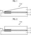
- Figs. 1 and 2 are cross-sectional views schematically showing an example of a bonding structure according to Embodiment 1.
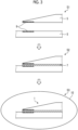
- Fig. 3 is an explanatory view showing a bonding method according to Embodiment 1.
- a bonding method and a bonding structure 1 according to Embodiment 1 composite materials 5 as adherends are bonded through an adhesive agent.
- a stress concentration portion in which a stress is concentrated at a predetermined portion is generated by applying a stress.
- the composite materials 5 are bonded to each other so as to have a strength that can withstand the generated stress concentration portion.
- the bonding structure 1 includes a pair of composite materials 5 provided to face each other, an adhesive agent 7 which bonds the pair of composite materials 5, and a reinforcing member 9 provided at a stress concentration portion.
- examples of the bonding structure 1 include a bonding structure 1a shown in Fig. 1 and a bonding structure 1b shown in Fig. 2 .
- the pair of composite materials 5 includes a thermosetting resin and a reinforced fiber.
- the thermosetting resin is an epoxy-based resin.
- the thermosetting resin may be any resin as long as it undergoes a crosslinking reaction.
- the reinforced fiber is a carbon fiber, but is not particularly limited, and may be any fiber. That is, carbon fiber reinforced plastics are used as the composite materials 5, but any composite material may be used as long as a crosslinking reaction occurs.
- the pair of composite materials 5 is, for example, a skin and a stringer, and the bonding structure 1 is a structure in which the stringer is bonded to an inner side of the skin. In the pair of composite materials 5, surfaces facing each other are surfaces to be bonded, and the pair of surfaces to be bonded are parallel to each other.
- one composite material 5 (an upper side in Fig. 1 ) of the pair of composite materials 5 has a tapered shape having a thickness decreasing toward an outer side.
- one composite material 5 (an upper side in Fig. 2 ) of the pair of composite materials 5 has a flat plate shape having the same thickness toward an outer side.
- the adhesive agent 7 includes a thermosetting resin.
- the thermosetting resin is an epoxy-based resin as in the composite material 5, but may be any resin as long as it undergoes a crosslinking reaction.
- the adhesive agent 7 may be an adhesive agent formed in a film form which is heat-cured, or may be an adhesive agent in a gel form which is applied and heat-cured.
- the adhesive agent 7 has a uniform thickness over the surfaces to be bonded.
- the reinforcing member 9 is provided on a surface of the composite material 5 on a side on which the adhesive agent 7 is disposed, that is, on the surface to be bonded.
- the reinforcing member 9 is provided at a portion where the stress concentration portion is generated.
- the portion where the stress concentration occurs can be predicted by analysis or the like, and a size of a crack that occurs in the stress concentrated portion can also be predicted by analysis or the like.
- the obtained crack has a critical crack length from a starting point to an end point of the crack. Since the starting point of the crack is an edge portion (an exposed portion) of the bonded portion, the reinforcing member 9 is provided from the edge portion of the bonded portion over the critical crack length.
- the reinforcing member 9 is a material having a higher toughness than that of the composite material 5.
- the reinforcing member 9 is, for example, a carbon fiber woven fabric or Vectran (registered trademark), and a reinforced fiber preform in a dry state or a composite material including a thermosetting resin and a reinforced fiber is used.
- the reinforcing member 9 is provided integrally with the composite material 5, and is molded so that a surface of the reinforcing member 9 on a side on which the adhesive agent 7 is disposed, that is, a surface to be bonded of the reinforcing member 9 is flush with the surface to be bonded of the composite material 5. Therefore, the adhesive agent 7 has a uniform thickness over the surfaces to be bonded of the reinforcing member 9 and the composite material 5.
- Fig. 3 is an explanatory view showing a bonding method according to Embodiment 1.
- molecular weights of the thermosetting resin included in the composite material 5 and the thermosetting resin included in the adhesive agent 7 are different from each other.
- the thermosetting resin included in the composite material 5 has a larger molecular weight than that of the thermosetting resin included in the adhesive agent 7.
- the thermosetting resin included in the adhesive agent 7 has a smaller molecular weight than that of the thermosetting resin included in the composite material 5. This is because a rigidity of the composite material 5 is high, while a viscosity of the adhesive agent 7 is decreased to increase infiltration.
- each of the pair of composite materials 5 to be bonded is molded (a step S1).
- the composite material 5 before curing is formed by laminating a reinforced fiber sheet such as a prepreg obtained by impregnating the reinforced fiber with the thermosetting resin.
- the reinforcing member 9 is disposed on the surface to be bonded of the composite material 5, which is a portion where the stress concentration portion is generated. In this case, the reinforcing member 9 is disposed from a predicted starting point of the crack in the bonding structure 1 to the critical crack length of the crack.
- the composite material 5 and the reinforcing member 9 are heated to be integrally molded such that the thermosetting resin of the composite material 5 is in a semi-cured state.
- a crosslinking degree (a curing degree) of the thermosetting resin is set in a range of 40% to 80% as the semi-cured state.
- the composite material 5 in the semi-cured state can be cured to the extent that the composite material 5 can be easily handled, and thus the handling or positioning of the composite material 5 are easily performed, and an assembly work is facilitated.
- the crosslinking degree of the thermosetting resin is set to 80% or less.
- a heating temperature is decreased or a heating time is shortened, compared to a case where the thermosetting resin is brought into a fully cured state.
- the molding is performed so that the surface to be bonded of the composite material 5 is flush with the surface to be bonded of the reinforcing member 9 using a molding tool.
- the surfaces to be bonded of the composite materials 5 are caused to face each other, and the adhesive agent 7 is disposed between the composite materials 5 (a step S2).
- the adhesive agent 7 is disposed so as to have a uniform thickness over the surface to be bonded.
- the surface roughness of the surface to be bonded of the reinforcing member 9 may be higher than that of the surface to be bonded of the composite material 5.
- the bonding method the pair of composite materials 5 are bonded to each other to form the bonding structure 1 by putting the pair of composite materials 5 and the adhesive agent 7 bonded in the step S2 into a heating furnace 10 to heat and cure the adhesive agent 7 (a step S3).
- the thermosetting resins included in the composite materials 5 and the adhesive agent 7 are fully cured.
- the fully cured state is a state in which the crosslinking of the thermosetting resins by heating does not proceed to a predetermined crosslinking degree or more.
- the crosslinking degree of the thermosetting resin of the adhesive agent 7 is higher than that of the thermosetting resin of the composite material 5.
- the composite material 5 is in the semi-cured state in the step S1, and the composite materials 5 and the adhesive agent 7 are in the fully cured state in the step S3.
- the thermosetting resin of the composite material 5 is brought into the semi-cured state to remain the thermosetting resins which are unreacted for the crosslinking reaction
- the thermosetting resin of the composite material 5 and the thermosetting resin of the adhesive agent 7, which are unreacted for the crosslinking reaction are subjected to the crosslinking reaction, and accordingly, it is possible to increase bonding strength between the composite material 5 and the adhesive agent 7.
- the cured bonding structure 1 is extracted from the heating furnace 10, and the series of steps is completed.
- the surface to be bonded of the reinforcing member 9 was flush with the surface to be bonded of the composite material 5, but is not limited thereto, and the surface to be bonded of the reinforcing member 9 may protrude from the surface to be bonded of the composite material 5.
- the reinforcing member 9 may be disposed by being laminated on the composite material 5 before curing, or a portion of the composite material 5 on which the reinforcing member 9 is disposed may be cut out and disposed, and the reinforcing member 9 is not particularly limited.
- the composite material 5 is brought into the semi-cured state in the step S1, and the composite material 5 and the adhesive agent 7 are brought into the fully cured state in the step S3, but the composite material 5 may be brought into the fully cured state in the step S1.
- Fig. 4 is a cross-sectional view schematically showing a bonding structure according to Embodiment 2.
- a bonding structure 21 of Embodiment 2 has a configuration in which the reinforcing member 9 of Embodiment 1 is omitted.
- the composite material 5 in the bonding method of bonding the composite materials 5 to each other using the adhesive agent 7, the composite material 5 is brought into the semi-cured state in the step S1, and the composite material 5 and the adhesive agent 7 are brought into the fully cured state in the step S3.
- Embodiment 2 in the configuration in which the reinforcing member 9 is omitted, the bonding method of Embodiment 1 is performed, thereby improving the bonding strength between the composite materials 5 by the adhesive agent 7.
- the bonding method and the bonding structure according to Embodiments 1 and 2 are understood as follows, for example.
- the adherends and the adhesive agent 7 include a thermosetting resin
- the method includes a step S1 of molding the adherends, a step S2 of disposing the adhesive agent 7 between the adherends, and a step S3 of forming the bonding structure 1 by curing the adhesive agent 7 and bonding the adherends, and, in the step S1 of molding the adherends, a reinforcing member 9 having a toughness higher than a toughness of the adherends is disposed on and integrally molded with a surface of the adherends on a side on which the adhesive agent 7 is disposed.
- the cracks can be suppressed from progressing to the composite material 5 by the reinforcing member 9 by disposing the reinforcing member 9 having a toughness higher than that of the composite material 5. Therefore, the strength of the bonded portion of the adhesive agent 7 can be improved.
- the reinforcing member 9 is disposed from a predicted starting point of a crack over a critical crack length of the crack in the bonding structure 1.
- the cracks can be suppressed from progressing to the composite material 5 by the reinforcing member 9.
- a surface on which the reinforcing member 9 is disposed is molded to be flush with the surface of the adherends on the side on which the adhesive agent 7 is disposed.
- a thickness of the adhesive agent 7 can be made uniform, and therefore, the thickness of the adhesive agent 7 can be easily managed.
- a surface roughness of a surface on which the reinforcing member 9 is disposed is higher than the surface of the adherends on the side on which the adhesive agent 7 is disposed.
- a bonding area of the reinforcing member 9 with respect to the adhesive agent 7 can be increased, and therefore, the bonding strength can be further increased.
- thermosetting resin included in the adherends in the step S1 of molding the adherends, the thermosetting resin included in the adherends is brought into a semi-cured state, and in the step S3 of forming the bonding structure 1, the thermosetting resin included in the adherends and the adhesive agent 7 is fully cured.
- thermosetting resin of the composite material 5 is brought into the semi-cured state to remain the thermosetting resins which are unreacted for the crosslinking reaction, and in the step S3, the thermosetting resin of the composite material 5 and the thermosetting resin of the adhesive agent 7, which are unreacted for the crosslinking reaction, are subjected to the crosslinking reaction, and accordingly, it is possible to increase bonding strength between the composite material 5 and the adhesive agent 7.
- a crosslinking degree of the thermosetting resin is in a range of 40% to 80%.
- thermosetting resin which is unreacted for the crosslinking reaction, and it is possible to easily handle the composite material 5 in the semi-cured state.
- thermosetting resin included in the adherend has a larger molecular weight than a molecular weight of the thermosetting resin included in the adhesive agent.
- a rigidity of the cured composite material 5 can be increased, and a viscosity of the adhesive agent 7 during curing is decreased to increase infiltration. Therefore, the adhesive agent 7 can be allowed to spread over the bonding interface between the adherends without a gap.
- a crosslinking degree of the thermosetting resin included in the adhesive agent 7 is higher than a crosslinking degree of the thermosetting resin included in the adherend.
- the composite material 5 and the adhesive agent 7 can be suitably fully cured.
- the adherends and the adhesive agent 7 include a thermosetting resin
- the method includes a step S1 of molding the adherends so that the thermosetting resin included in the adherends is brought into a semi-cured state, a step S2 of disposing the adhesive agent 7 between the adherends, and a step S3 of forming the bonding structure 1 by fully curing the thermosetting resin included in the adherends and the adhesive agent 7 and bonding the adherends to each other.
- thermosetting resin of the composite material 5 is brought into the semi-cured state to remain the thermosetting resins which are unreacted for the crosslinking reaction
- thermosetting resin of the composite material 5 and the thermosetting resin of the adhesive agent 7, which are unreacted for the crosslinking reaction are subjected to the crosslinking reaction, and accordingly, it is possible to increase bonding strength between the composite material 5 and the adhesive agent 7. Therefore, the strength of the bonded portion of the adhesive agent 7 can be improved.
- the bonding structure 1 includes a pair of adherends (composite materials 5) which are provided to face each other, an adhesive agent 7 which is provided between the adherends and bonds the pair of adherends to each other, and a reinforcing member 9 which is provided on a surface of the adherends on a side on which the adhesive agent 7 is disposed, and is a material having a higher toughness than a toughness of the adherends.
- the cracks can be suppressed from progressing to the composite material 5 by the reinforcing member 9, and the strength of the bonded portion of the adhesive agent 7 can be improved.
Landscapes
- Engineering & Computer Science (AREA)
- Mechanical Engineering (AREA)
- Chemical & Material Sciences (AREA)
- Chemical Kinetics & Catalysis (AREA)
- General Chemical & Material Sciences (AREA)
- Organic Chemistry (AREA)
- Lining Or Joining Of Plastics Or The Like (AREA)
- Adhesives Or Adhesive Processes (AREA)
- Laminated Bodies (AREA)
Abstract
Description
- The present disclosure relates to a bonding method and a bonding structure.
- In the related art, a method of manufacturing a composite material is known, in which a material for an article to be molded is primarily cured, the primarily cured material for the article to be molded is assembled with another material for an article to be molded through an adhesive agent to form an assembly, the assembly is heated to secondarily cure and integrate the material for the article to be molded (for example, refer to PTL 1).
- [PTL 1]
Japanese Unexamined Patent Application Publication No. 2014-136418 - By the way, a strength of a bonding structure in which composite materials are bonded to each other with an adhesive agent is lower than that of a composite material which is integrally molded (integrally molded structure). Therefore, an application range of the bonding structure is limited to the integrally molded structure, and it is desired to improve the strength of the bonding structure.
- Therefore, an object of the present disclosure is to provide a bonding method and a bonding structure capable of improving the strength of a bonded portion. Solution to Problem
- In a bonding method for bonding adherends to each other through an adhesive agent of the present disclosure, the adherends and the adhesive agent include a thermosetting resin, the method includes a step of molding the adherends, a step of disposing the adhesive agent between the adherends, and a step of forming a bonding structure by curing the adhesive agent and bonding the adherends to each other, in which, in the step of molding the adherends, a reinforcing member having a toughness higher than a toughness of the adherends is disposed on and integrally molded with a surface of the adherends on a side on which the adhesive agent is disposed.
- In another bonding method for bonding adherends to each other through an adhesive agent of the present disclosure, the adherends and the adhesive agent include a thermosetting resin, the method includes a step of molding the adherends so that the thermosetting resin included in the adherends is in a semi-cured state, a step of disposing the adhesive agent between the adherends, and a step of forming the bonding structure by fully curing the thermosetting resin included in the adherends and the adhesive agent and bonding the adherends to each other.
- A bonding structure of the present disclosure includes a pair of adherends which are provided to face each other, an adhesive agent which is provided between the adherends and bonds the pair of adherends, and a reinforcing member which is provided on a surface of the adherends on a side on which the adhesive agent is disposed, and is a material having a higher toughness than a toughness of the adherends.
- According to the present disclosure, it is possible to improve a strength of a bonded portion.
-
-
Fig. 1 is a cross-sectional view schematically showing an example of a bonding structure according toEmbodiment 1. -
Fig. 2 is a cross-sectional view schematically showing an example of a bonding structure according toEmbodiment 1. -
Fig. 3 is an explanatory view showing a bonding method according toEmbodiment 1. -
Fig. 4 is a cross-sectional view schematically showing a bonding structure according to Embodiment 2. - Hereinafter, an embodiment according to the present disclosure will be described in detail with reference to the drawings. It should be noted that the present disclosure is not limited to this embodiment. Further, components of the following embodiments include components that can be easily substituted by those skilled in the art or components that are substantially the same as the components of the following embodiments. Further, the components described below can be combined as appropriate, and in a case where a plurality of embodiments are present, the embodiments can be combined.
-
Figs. 1 and 2 are cross-sectional views schematically showing an example of a bonding structure according toEmbodiment 1.Fig. 3 is an explanatory view showing a bonding method according toEmbodiment 1. - In a bonding method and a
bonding structure 1 according toEmbodiment 1,composite materials 5 as adherends are bonded through an adhesive agent. In thebonding structure 1, a stress concentration portion in which a stress is concentrated at a predetermined portion is generated by applying a stress. In thebonding structure 1, thecomposite materials 5 are bonded to each other so as to have a strength that can withstand the generated stress concentration portion. - The
bonding structure 1 includes a pair ofcomposite materials 5 provided to face each other, anadhesive agent 7 which bonds the pair ofcomposite materials 5, and a reinforcingmember 9 provided at a stress concentration portion. In addition, examples of thebonding structure 1 include abonding structure 1a shown inFig. 1 and abonding structure 1b shown inFig. 2 . - The pair of
composite materials 5 includes a thermosetting resin and a reinforced fiber. The thermosetting resin is an epoxy-based resin. The thermosetting resin may be any resin as long as it undergoes a crosslinking reaction. The reinforced fiber is a carbon fiber, but is not particularly limited, and may be any fiber. That is, carbon fiber reinforced plastics are used as thecomposite materials 5, but any composite material may be used as long as a crosslinking reaction occurs. The pair ofcomposite materials 5 is, for example, a skin and a stringer, and thebonding structure 1 is a structure in which the stringer is bonded to an inner side of the skin. In the pair ofcomposite materials 5, surfaces facing each other are surfaces to be bonded, and the pair of surfaces to be bonded are parallel to each other. Here, in thebonding structure 1a shown inFig. 1 , one composite material 5 (an upper side inFig. 1 ) of the pair ofcomposite materials 5 has a tapered shape having a thickness decreasing toward an outer side. In addition, in thebonding structure 1b shown inFig. 2 , one composite material 5 (an upper side inFig. 2 ) of the pair ofcomposite materials 5 has a flat plate shape having the same thickness toward an outer side. - The
adhesive agent 7 includes a thermosetting resin. The thermosetting resin is an epoxy-based resin as in thecomposite material 5, but may be any resin as long as it undergoes a crosslinking reaction. Theadhesive agent 7 may be an adhesive agent formed in a film form which is heat-cured, or may be an adhesive agent in a gel form which is applied and heat-cured. Theadhesive agent 7 has a uniform thickness over the surfaces to be bonded. - The reinforcing
member 9 is provided on a surface of thecomposite material 5 on a side on which theadhesive agent 7 is disposed, that is, on the surface to be bonded. In addition, the reinforcingmember 9 is provided at a portion where the stress concentration portion is generated. The portion where the stress concentration occurs can be predicted by analysis or the like, and a size of a crack that occurs in the stress concentrated portion can also be predicted by analysis or the like. The obtained crack has a critical crack length from a starting point to an end point of the crack. Since the starting point of the crack is an edge portion (an exposed portion) of the bonded portion, the reinforcingmember 9 is provided from the edge portion of the bonded portion over the critical crack length. The reinforcingmember 9 is a material having a higher toughness than that of thecomposite material 5. The reinforcingmember 9 is, for example, a carbon fiber woven fabric or Vectran (registered trademark), and a reinforced fiber preform in a dry state or a composite material including a thermosetting resin and a reinforced fiber is used. - In addition, the reinforcing
member 9 is provided integrally with thecomposite material 5, and is molded so that a surface of the reinforcingmember 9 on a side on which theadhesive agent 7 is disposed, that is, a surface to be bonded of the reinforcingmember 9 is flush with the surface to be bonded of thecomposite material 5. Therefore, theadhesive agent 7 has a uniform thickness over the surfaces to be bonded of the reinforcingmember 9 and thecomposite material 5. - A surface roughness of the surface to be bonded of the reinforcing
member 9 may be higher than that of the surface to be bonded of thecomposite material 5 during bonding. - Next, a bonding method for bonding the
composite materials 5 to each other using theadhesive agent 7 will be described with reference toFig. 3. Fig. 3 is an explanatory view showing a bonding method according toEmbodiment 1. Here, molecular weights of the thermosetting resin included in thecomposite material 5 and the thermosetting resin included in theadhesive agent 7 are different from each other. Specifically, the thermosetting resin included in thecomposite material 5 has a larger molecular weight than that of the thermosetting resin included in theadhesive agent 7. In other words, the thermosetting resin included in theadhesive agent 7 has a smaller molecular weight than that of the thermosetting resin included in thecomposite material 5. This is because a rigidity of thecomposite material 5 is high, while a viscosity of theadhesive agent 7 is decreased to increase infiltration. - As shown in
Fig. 3 , in the bonding method, first, each of the pair ofcomposite materials 5 to be bonded is molded (a step S1). In the step S1, thecomposite material 5 before curing is formed by laminating a reinforced fiber sheet such as a prepreg obtained by impregnating the reinforced fiber with the thermosetting resin. After that, the reinforcingmember 9 is disposed on the surface to be bonded of thecomposite material 5, which is a portion where the stress concentration portion is generated. In this case, the reinforcingmember 9 is disposed from a predicted starting point of the crack in thebonding structure 1 to the critical crack length of the crack. In the step S1, thecomposite material 5 and the reinforcingmember 9 are heated to be integrally molded such that the thermosetting resin of thecomposite material 5 is in a semi-cured state. In the step S1, a crosslinking degree (a curing degree) of the thermosetting resin is set in a range of 40% to 80% as the semi-cured state. In a case where the crosslinking degree of the thermosetting resin is set to 40% or more, thecomposite material 5 in the semi-cured state can be cured to the extent that thecomposite material 5 can be easily handled, and thus the handling or positioning of thecomposite material 5 are easily performed, and an assembly work is facilitated. In addition, in a case where the crosslinking degree of the thermosetting resin is more than 80%, a covalent bond generated at a bonding interface is reduced, and the strength at the interface is reduced. Therefore, the crosslinking degree of the thermosetting resin is set to 80% or less. In the step S1, in order to bring the thermosetting resin of thecomposite material 5 into the semi-cured state, a heating temperature is decreased or a heating time is shortened, compared to a case where the thermosetting resin is brought into a fully cured state. In addition, in the step S1, in a case where thecomposite material 5 and the reinforcingmember 9 are integrally molded, the molding is performed so that the surface to be bonded of thecomposite material 5 is flush with the surface to be bonded of the reinforcingmember 9 using a molding tool. - Subsequently, in the bonding method, the surfaces to be bonded of the
composite materials 5 are caused to face each other, and theadhesive agent 7 is disposed between the composite materials 5 (a step S2). In the step S2, theadhesive agent 7 is disposed so as to have a uniform thickness over the surface to be bonded. In the step S2, the surface roughness of the surface to be bonded of the reinforcingmember 9 may be higher than that of the surface to be bonded of thecomposite material 5. - Next, in the bonding method, the pair of
composite materials 5 are bonded to each other to form thebonding structure 1 by putting the pair ofcomposite materials 5 and theadhesive agent 7 bonded in the step S2 into aheating furnace 10 to heat and cure the adhesive agent 7 (a step S3). In the step S3, the thermosetting resins included in thecomposite materials 5 and theadhesive agent 7 are fully cured. Here, the fully cured state is a state in which the crosslinking of the thermosetting resins by heating does not proceed to a predetermined crosslinking degree or more. Specifically, in the step S3, in a case where the thermosetting resins of thecomposite materials 5 and theadhesive agent 7 are fully cured, the crosslinking degree of the thermosetting resin of theadhesive agent 7 is higher than that of the thermosetting resin of thecomposite material 5. - As described above, in the bonding method of
Embodiment 1, thecomposite material 5 is in the semi-cured state in the step S1, and thecomposite materials 5 and theadhesive agent 7 are in the fully cured state in the step S3. In the step S1, the thermosetting resin of thecomposite material 5 is brought into the semi-cured state to remain the thermosetting resins which are unreacted for the crosslinking reaction, and in the step S3, the thermosetting resin of thecomposite material 5 and the thermosetting resin of theadhesive agent 7, which are unreacted for the crosslinking reaction, are subjected to the crosslinking reaction, and accordingly, it is possible to increase bonding strength between thecomposite material 5 and theadhesive agent 7. - In the bonding method, after the execution of the step S3, the cured
bonding structure 1 is extracted from theheating furnace 10, and the series of steps is completed. - In
Embodiment 1, the surface to be bonded of the reinforcingmember 9 was flush with the surface to be bonded of thecomposite material 5, but is not limited thereto, and the surface to be bonded of the reinforcingmember 9 may protrude from the surface to be bonded of thecomposite material 5. In addition, the reinforcingmember 9 may be disposed by being laminated on thecomposite material 5 before curing, or a portion of thecomposite material 5 on which the reinforcingmember 9 is disposed may be cut out and disposed, and the reinforcingmember 9 is not particularly limited. - In addition, in
Embodiment 1, thecomposite material 5 is brought into the semi-cured state in the step S1, and thecomposite material 5 and theadhesive agent 7 are brought into the fully cured state in the step S3, but thecomposite material 5 may be brought into the fully cured state in the step S1. - Next, Embodiment 2 will be described with reference to
Fig. 4 . In Embodiment 2, in order to avoid overlapping descriptions, portions different from those inEmbodiment 1 will be described, and portions having the same configurations as those inEmbodiment 1 will be described with them denoted by the same reference numerals.Fig. 4 is a cross-sectional view schematically showing a bonding structure according to Embodiment 2. - A bonding structure 21 of Embodiment 2 has a configuration in which the reinforcing
member 9 ofEmbodiment 1 is omitted. In the bonding structure 21 of Embodiment 2, in the bonding method of bonding thecomposite materials 5 to each other using theadhesive agent 7, thecomposite material 5 is brought into the semi-cured state in the step S1, and thecomposite material 5 and theadhesive agent 7 are brought into the fully cured state in the step S3. - That is, in Embodiment 2, in the configuration in which the reinforcing
member 9 is omitted, the bonding method ofEmbodiment 1 is performed, thereby improving the bonding strength between thecomposite materials 5 by theadhesive agent 7. - As described above, the bonding method and the bonding structure according to
Embodiments 1 and 2 are understood as follows, for example. - In a bonding method for bonding adherends (composite materials 5) to each other through an
adhesive agent 7 according to a first aspect, the adherends and theadhesive agent 7 include a thermosetting resin, the method includes a step S1 of molding the adherends, a step S2 of disposing theadhesive agent 7 between the adherends, and a step S3 of forming thebonding structure 1 by curing theadhesive agent 7 and bonding the adherends, and, in the step S1 of molding the adherends, a reinforcingmember 9 having a toughness higher than a toughness of the adherends is disposed on and integrally molded with a surface of the adherends on a side on which theadhesive agent 7 is disposed. - According to this configuration, even in a case where cracks occur in the bonded portion of the
adhesive agent 7, the cracks can be suppressed from progressing to thecomposite material 5 by the reinforcingmember 9 by disposing the reinforcingmember 9 having a toughness higher than that of thecomposite material 5. Therefore, the strength of the bonded portion of theadhesive agent 7 can be improved. - As a second aspect, in the bonding method according to the first aspect, in the step S1 of molding the adherends, the reinforcing
member 9 is disposed from a predicted starting point of a crack over a critical crack length of the crack in thebonding structure 1. - According to this configuration, the cracks can be suppressed from progressing to the
composite material 5 by the reinforcingmember 9. - As a third aspect, in the bonding method according to the first or second aspect, in the step S1 of molding the adherends, a surface on which the reinforcing
member 9 is disposed is molded to be flush with the surface of the adherends on the side on which theadhesive agent 7 is disposed. - According to this configuration, a thickness of the
adhesive agent 7 can be made uniform, and therefore, the thickness of theadhesive agent 7 can be easily managed. - As a fourth aspect, in the bonding method according to any one of the first to third aspects, in the step S2 of disposing the adhesive agent, a surface roughness of a surface on which the reinforcing
member 9 is disposed is higher than the surface of the adherends on the side on which theadhesive agent 7 is disposed. - According to this configuration, a bonding area of the reinforcing
member 9 with respect to theadhesive agent 7 can be increased, and therefore, the bonding strength can be further increased. - As a fifth aspect, in the bonding method according to any one of the first to fourth aspects, in the step S1 of molding the adherends, the thermosetting resin included in the adherends is brought into a semi-cured state, and in the step S3 of forming the
bonding structure 1, the thermosetting resin included in the adherends and theadhesive agent 7 is fully cured. - According to this configuration, in the step S1, the thermosetting resin of the
composite material 5 is brought into the semi-cured state to remain the thermosetting resins which are unreacted for the crosslinking reaction, and in the step S3, the thermosetting resin of thecomposite material 5 and the thermosetting resin of theadhesive agent 7, which are unreacted for the crosslinking reaction, are subjected to the crosslinking reaction, and accordingly, it is possible to increase bonding strength between thecomposite material 5 and theadhesive agent 7. - As a sixth aspect, in the bonding method according to the fifth aspect, in the semi-cured state, a crosslinking degree of the thermosetting resin is in a range of 40% to 80%.
- According to this configuration, it is possible to appropriately remain the thermosetting resin which is unreacted for the crosslinking reaction, and it is possible to easily handle the
composite material 5 in the semi-cured state. - In a seventh aspect, in the bonding method according to the fifth or sixth aspect, the thermosetting resin included in the adherend has a larger molecular weight than a molecular weight of the thermosetting resin included in the adhesive agent.
- According to this configuration, a rigidity of the cured
composite material 5 can be increased, and a viscosity of theadhesive agent 7 during curing is decreased to increase infiltration. Therefore, theadhesive agent 7 can be allowed to spread over the bonding interface between the adherends without a gap. - As an eighth aspect, in the bonding method according to the seventh aspect, in the step S3 of forming the
bonding structure 1, a crosslinking degree of the thermosetting resin included in theadhesive agent 7 is higher than a crosslinking degree of the thermosetting resin included in the adherend. - According to this configuration, even in a case where thermosetting resins having different molecular weights are used, the
composite material 5 and theadhesive agent 7 can be suitably fully cured. - In a bonding method for bonding adherends to each other through an
adhesive agent 7 according to a ninth aspect, the adherends and theadhesive agent 7 include a thermosetting resin, the method includes a step S1 of molding the adherends so that the thermosetting resin included in the adherends is brought into a semi-cured state, a step S2 of disposing theadhesive agent 7 between the adherends, and a step S3 of forming thebonding structure 1 by fully curing the thermosetting resin included in the adherends and theadhesive agent 7 and bonding the adherends to each other. - According to this configuration, in the step S1, the thermosetting resin of the
composite material 5 is brought into the semi-cured state to remain the thermosetting resins which are unreacted for the crosslinking reaction, and in the step S3, the thermosetting resin of thecomposite material 5 and the thermosetting resin of theadhesive agent 7, which are unreacted for the crosslinking reaction, are subjected to the crosslinking reaction, and accordingly, it is possible to increase bonding strength between thecomposite material 5 and theadhesive agent 7. Therefore, the strength of the bonded portion of theadhesive agent 7 can be improved. - The
bonding structure 1 according to a tenth aspect includes a pair of adherends (composite materials 5) which are provided to face each other, anadhesive agent 7 which is provided between the adherends and bonds the pair of adherends to each other, and a reinforcingmember 9 which is provided on a surface of the adherends on a side on which theadhesive agent 7 is disposed, and is a material having a higher toughness than a toughness of the adherends. - According to this configuration, the cracks can be suppressed from progressing to the
composite material 5 by the reinforcingmember 9, and the strength of the bonded portion of theadhesive agent 7 can be improved. -
- 1 bonding structure
- 5 composite material
- 7 adhesive agent
- 9 reinforcing member
- 10 heating furnace
- 21 bonding structure
Claims (10)
- A bonding method for bonding adherends to each other through an adhesive agent, in which the adherends and the adhesive agent include a thermosetting resin, the method comprising:a step of molding the adherends;a step of disposing the adhesive agent between the adherends; anda step of forming a bonding structure by curing the adhesive agent and bonding the adherends to each other,wherein, in the step of molding the adherends,a reinforcing member having a toughness higher than a toughness of the adherends is disposed on and integrally molded with a surface of the adherends on a side on which the adhesive agent is disposed.
- The bonding method according to claim 1,wherein, in the step of molding the adherends,the reinforcing member is disposed from a predicted starting point of a crack over a critical crack length of the crack in the bonding structure.
- The bonding method according to claim 1,wherein, in the step of molding the adherends,a surface on which the reinforcing member is disposed is molded to be flush with the surface of the adherends on the side on which the adhesive agent is disposed.
- The bonding method according to claim 1,wherein, in the step of disposing the adhesive agent,a surface roughness of a surface on which the reinforcing member is disposed is higher than the surface of the adherends on the side on which the adhesive agent is disposed.
- The bonding method according to claim 1,wherein, in the step of molding the adherends,the thermosetting resin included in the adherends is brought into a semi-cured state, andin the step of forming the bonding structure,the thermosetting resin included in the adherends and the adhesive agent is fully cured.
- The bonding method according to claim 5,
wherein, in the semi-cured state, a crosslinking degree of the thermosetting resin is in a range of 40% to 80%. - The bonding method according to claim 5,
wherein the thermosetting resin included in the adherend has a larger molecular weight than a molecular weight of the thermosetting resin included in the adhesive agent. - The bonding method according to claim 7,wherein, in the step of forming the bonding structure,a crosslinking degree of the thermosetting resin included in the adhesive agent is higher than a crosslinking degree of the thermosetting resin included in the adherend.
- A bonding method for bonding adherends to each other through an adhesive agent, in which the adherends and the adhesive agent include a thermosetting resin, the method comprising:a step of molding the adherends so that the thermosetting resin included in the adherends is brought into a semi-cured state;a step of disposing the adhesive agent between the adherends; anda step of forming a bonding structure by fully curing the thermosetting resin included in the adherends and the adhesive agent and bonding the adherends to each other.
- A bonding structure comprising:a pair of adherends which are provided to face each other;an adhesive agent which is provided between the adherends and bonds the pair of adherends to each other; anda reinforcing member which is provided on a surface of the adherends on a side on which the adhesive agent is disposed, and is a material having a higher toughness than a toughness of the adherends.
Applications Claiming Priority (2)
| Application Number | Priority Date | Filing Date | Title |
|---|---|---|---|
| JP2022173595A JP2024064762A (en) | 2022-10-28 | 2022-10-28 | Adhesion method and adhesion structure |
| PCT/JP2023/038620 WO2024090502A1 (en) | 2022-10-28 | 2023-10-26 | Bonding method and bonding structure |
Publications (2)
| Publication Number | Publication Date |
|---|---|
| EP4556204A1 true EP4556204A1 (en) | 2025-05-21 |
| EP4556204A4 EP4556204A4 (en) | 2025-10-15 |
Family
ID=90830823
Family Applications (1)
| Application Number | Title | Priority Date | Filing Date |
|---|---|---|---|
| EP23882706.7A Pending EP4556204A4 (en) | 2022-10-28 | 2023-10-26 | BONDING METHOD AND BONDING STRUCTURE |
Country Status (3)
| Country | Link |
|---|---|
| EP (1) | EP4556204A4 (en) |
| JP (1) | JP2024064762A (en) |
| WO (1) | WO2024090502A1 (en) |
Family Cites Families (7)
| Publication number | Priority date | Publication date | Assignee | Title |
|---|---|---|---|---|
| JP4338550B2 (en) * | 2004-03-04 | 2009-10-07 | 東レ株式会社 | Method for manufacturing FRP structure |
| US9434142B2 (en) * | 2012-01-26 | 2016-09-06 | E I Du Pont De Nemours And Company | Method of making a sandwich panel |
| MX377479B (en) * | 2012-11-26 | 2025-03-10 | Cytec Ind Inc | UNION OF COMPOSITE MATERIALS. |
| JP6271130B2 (en) | 2013-01-18 | 2018-01-31 | 三菱重工業株式会社 | Manufacturing method of composite material |
| DE102016111635A1 (en) * | 2016-06-24 | 2017-12-28 | Deutsches Zentrum für Luft- und Raumfahrt e.V. | Method for joining two fiber composite joining partners |
| JP6964502B2 (en) * | 2017-12-07 | 2021-11-10 | 三菱重工業株式会社 | How to join composite materials |
| KR20200100789A (en) * | 2017-12-21 | 2020-08-26 | 사이텍 인더스트리스 인코포레이티드 | Peel ply for surface manufacturing and bonding method using the same |
-
2022
- 2022-10-28 JP JP2022173595A patent/JP2024064762A/en active Pending
-
2023
- 2023-10-26 WO PCT/JP2023/038620 patent/WO2024090502A1/en not_active Ceased
- 2023-10-26 EP EP23882706.7A patent/EP4556204A4/en active Pending
Also Published As
| Publication number | Publication date |
|---|---|
| EP4556204A4 (en) | 2025-10-15 |
| JP2024064762A (en) | 2024-05-14 |
| WO2024090502A1 (en) | 2024-05-02 |
Similar Documents
| Publication | Publication Date | Title |
|---|---|---|
| JP5329649B2 (en) | Turbine blade half manufacturing method, turbine blade half, turbine blade manufacturing method, and turbine blade | |
| RU2618055C2 (en) | Composite materials bonding | |
| US6527894B1 (en) | Method for producing fibre-reinforced plastic components | |
| US20100051183A1 (en) | Method of making lightweight structures | |
| JP2001048096A (en) | Manufacturing method of composite wing | |
| GB2448950B (en) | Manufacture of fibre-reinforced composite moulding | |
| EP3750698B1 (en) | Repair patch, repair patch molding method, and repair method for composite material | |
| JP6204093B2 (en) | Method for manufacturing reinforcing structure | |
| US20160176085A1 (en) | Method and system for producing composite structures | |
| US20200406600A1 (en) | Method for joining by bonding of parts, in particular composite parts having fibrous reinforcement | |
| CN101351327B (en) | Technology for manufacturing compound structure with embedded precuring mold | |
| EP4556204A1 (en) | Bonding method and bonding structure | |
| JP7236337B2 (en) | Composite material wing and molding method for composite material wing | |
| CN114311731A (en) | Segmented curing molding method for high-temperature-resistant bismaleimide resin-based composite material | |
| KR20170133769A (en) | Resin trasferring mold forming method and device | |
| WO2023062870A1 (en) | Metal-prepreg complex | |
| JP2014151558A (en) | Method for producing fiber-reinforced thermoplastic resin-integrated structure | |
| CN105818323A (en) | Process for attaching plastic film layer to carbon fiber surface layer | |
| US10800116B2 (en) | Moulding material and method of forming same | |
| US20190001588A1 (en) | Method for producing structures made of thermosetting composite materials by assembling composite constituent parts moulded by injection infusion of liquid resin | |
| EP4289604B1 (en) | Composite manufacturing method | |
| JP6831378B2 (en) | Improvements in or related to fiber reinforced composites | |
| KR102727319B1 (en) | Metal parts fastening structure of carbon fiber composite material and its formation method | |
| EP4509293A1 (en) | Method of joining a first blade module and a second blade module of a blade for a wind turbine | |
| US20160346973A1 (en) | Preform member bonding method |
Legal Events
| Date | Code | Title | Description |
|---|---|---|---|
| STAA | Information on the status of an ep patent application or granted ep patent |
Free format text: STATUS: THE INTERNATIONAL PUBLICATION HAS BEEN MADE |
|
| PUAI | Public reference made under article 153(3) epc to a published international application that has entered the european phase |
Free format text: ORIGINAL CODE: 0009012 |
|
| STAA | Information on the status of an ep patent application or granted ep patent |
Free format text: STATUS: REQUEST FOR EXAMINATION WAS MADE |
|
| 17P | Request for examination filed |
Effective date: 20250212 |
|
| AK | Designated contracting states |
Kind code of ref document: A1 Designated state(s): AL AT BE BG CH CY CZ DE DK EE ES FI FR GB GR HR HU IE IS IT LI LT LU LV MC ME MK MT NL NO PL PT RO RS SE SI SK SM TR |
|
| A4 | Supplementary search report drawn up and despatched |
Effective date: 20250911 |
|
| RIC1 | Information provided on ipc code assigned before grant |
Ipc: B29C 65/48 20060101AFI20250905BHEP Ipc: B32B 3/08 20060101ALI20250905BHEP Ipc: B32B 27/04 20060101ALI20250905BHEP Ipc: B32B 27/12 20060101ALI20250905BHEP Ipc: B29L 9/00 20060101ALI20250905BHEP Ipc: C09J 5/06 20060101ALI20250905BHEP |
|
| DAV | Request for validation of the european patent (deleted) | ||
| DAX | Request for extension of the european patent (deleted) |