EP4556180A1 - Personal grooming appliance - Google Patents
Personal grooming appliance Download PDFInfo
- Publication number
- EP4556180A1 EP4556180A1 EP23210257.4A EP23210257A EP4556180A1 EP 4556180 A1 EP4556180 A1 EP 4556180A1 EP 23210257 A EP23210257 A EP 23210257A EP 4556180 A1 EP4556180 A1 EP 4556180A1
- Authority
- EP
- European Patent Office
- Prior art keywords
- appliance
- spine
- locking element
- shaped teeth
- teeth
- Prior art date
- Legal status (The legal status is an assumption and is not a legal conclusion. Google has not performed a legal analysis and makes no representation as to the accuracy of the status listed.)
- Withdrawn
Links
Images


Classifications
-
- B—PERFORMING OPERATIONS; TRANSPORTING
- B26—HAND CUTTING TOOLS; CUTTING; SEVERING
- B26B—HAND-HELD CUTTING TOOLS NOT OTHERWISE PROVIDED FOR
- B26B19/00—Clippers or shavers operating with a plurality of cutting edges, e.g. hair clippers, dry shavers
- B26B19/20—Clippers or shavers operating with a plurality of cutting edges, e.g. hair clippers, dry shavers with provision for shearing hair of preselected or variable length
-
- B—PERFORMING OPERATIONS; TRANSPORTING
- B26—HAND CUTTING TOOLS; CUTTING; SEVERING
- B26B—HAND-HELD CUTTING TOOLS NOT OTHERWISE PROVIDED FOR
- B26B19/00—Clippers or shavers operating with a plurality of cutting edges, e.g. hair clippers, dry shavers
- B26B19/02—Clippers or shavers operating with a plurality of cutting edges, e.g. hair clippers, dry shavers of the reciprocating-cutter type
- B26B19/04—Cutting heads therefor; Cutters therefor; Securing equipment thereof
-
- B—PERFORMING OPERATIONS; TRANSPORTING
- B26—HAND CUTTING TOOLS; CUTTING; SEVERING
- B26B—HAND-HELD CUTTING TOOLS NOT OTHERWISE PROVIDED FOR
- B26B19/00—Clippers or shavers operating with a plurality of cutting edges, e.g. hair clippers, dry shavers
- B26B19/28—Drive layout for hair clippers or dry shavers, e.g. providing for electromotive drive
- B26B19/282—Motors without a rotating central drive shaft, e.g. linear motors
-
- B—PERFORMING OPERATIONS; TRANSPORTING
- B26—HAND CUTTING TOOLS; CUTTING; SEVERING
- B26B—HAND-HELD CUTTING TOOLS NOT OTHERWISE PROVIDED FOR
- B26B19/00—Clippers or shavers operating with a plurality of cutting edges, e.g. hair clippers, dry shavers
- B26B19/38—Details of, or accessories for, hair clippers, or dry shavers, e.g. housings, casings, grips, guards
- B26B19/3846—Blades; Cutters
-
- B—PERFORMING OPERATIONS; TRANSPORTING
- B26—HAND CUTTING TOOLS; CUTTING; SEVERING
- B26B—HAND-HELD CUTTING TOOLS NOT OTHERWISE PROVIDED FOR
- B26B19/00—Clippers or shavers operating with a plurality of cutting edges, e.g. hair clippers, dry shavers
- B26B19/38—Details of, or accessories for, hair clippers, or dry shavers, e.g. housings, casings, grips, guards
- B26B19/3853—Housing or handle
-
- B—PERFORMING OPERATIONS; TRANSPORTING
- B26—HAND CUTTING TOOLS; CUTTING; SEVERING
- B26B—HAND-HELD CUTTING TOOLS NOT OTHERWISE PROVIDED FOR
- B26B19/00—Clippers or shavers operating with a plurality of cutting edges, e.g. hair clippers, dry shavers
- B26B19/38—Details of, or accessories for, hair clippers, or dry shavers, e.g. housings, casings, grips, guards
- B26B19/3886—Actuating members, e.g. switches or control knobs
-
- B—PERFORMING OPERATIONS; TRANSPORTING
- B26—HAND CUTTING TOOLS; CUTTING; SEVERING
- B26B—HAND-HELD CUTTING TOOLS NOT OTHERWISE PROVIDED FOR
- B26B19/00—Clippers or shavers operating with a plurality of cutting edges, e.g. hair clippers, dry shavers
- B26B19/02—Clippers or shavers operating with a plurality of cutting edges, e.g. hair clippers, dry shavers of the reciprocating-cutter type
- B26B19/04—Cutting heads therefor; Cutters therefor; Securing equipment thereof
- B26B19/06—Cutting heads therefor; Cutters therefor; Securing equipment thereof involving co-operating cutting elements both of which have shearing teeth
- B26B19/063—Movable or adjustable cutting head
Definitions
- the subject-matter of the present disclosure relates to a personal grooming appliance, in particular a personal grooming appliance with a length setting functionality (e.g., a length of a trimming function).
- a length setting functionality e.g., a length of a trimming function
- Hair clippers usually comprise two sets of sharpened tooth-like blades which oscillate from side to side to form a cutting motion.
- the clipper may be moved (using a handle) so hair is positioned between the blades and cut with a scissor action when one set of blades slides sideways relative to the other set of blades.
- clippers would be provided with a comb attachment which set a length of the hair cut by ensuring a set separation between scalp and the sharpened blades. More recently, however, it has become common for such a comb attachment to be variable in length. That is, rather than one comb attachment being for one length of hair, a single comb attachment can be changed in position to change the length of haircut.
- a personal grooming appliance comprising an operational head (such as a hair clipper) including at least one part with an adjustable position, and a position setting assembly configured to set a position of the adjustable part (e.g., a separation from a cutting implement to set a length of hair trim, such as a clipper comb).
- the position setting assembly comprises a spine and a locking element, wherein the locking element is configured to releasably engage with the spine, and wherein the spine and the locking element comprise a plurality of interlocking triangularly shaped teeth.
- the triangularly shaped teeth are particularly advantageous for achieving sub 2 mm step size in the position adjustable part while maintaining suitable strength to withstand forces experienced by the position setting assembly during operation of the device.
- the triangularly shaped teeth are configured with a peak to peak delta of about 0.5 mm to about 1.5 mm, preferably about 1 mm, and may have a rounded peak shape.
- the triangularly shaped teeth are configured with a height of about 0.8 mm to about 0.95 mm.
- the triangularly shaped teeth are configured with a base width of about 0.8 mm to 1 mm.
- the triangularly shaped teeth are scalene shaped; that is, comprising a short wall, a long wall, and a base, each of different lengths, with the short wall and long wall being for engagement.
- the short engagement wall of each tooth on the spine is oriented towards a head portion of the personal grooming appliance, so as to provide better stability to the position setting assembly (i.e., so the interlock is less likely to accidentally disengage).
- the spine is arranged centrally with respect to a width of the personal grooming appliance, the width being orthogonal to the direction of movement of the adjustable part.
- the position setting assembly comprises a button configured to release the locking element from engagement with the spine when the button is actuated.
- the locking element is configured to slidably move with respect to the spine when the locking element is disengaged from the spine.
- the position setting assembly comprises an electric motor configured to move the locking element with respect to the spine when the locking element is disengaged from the spine.
- the grooming appliance 100 comprises a handle, or body, 102 for gripping and manipulating the appliance 100, an operational head 104 configured to provide a grooming operation, and a function button 106 (e.g., an on-off button) for controlling the operational head 104 (and optionally any other functions of the appliance 100).
- a function button 106 e.g., an on-off button
- the operational head 104 comprises at least one adjustable part 108 having an adjustable position. That is, a part which may be at least partly displaced in an X direction, Y direction, or Z direction, or combination thereof, with respect to the body 102 and/or any fixed component of the operational head 104.
- the operational head 104 may provide a hair clipping function, suitably comprising a cutter (not shown) configured to cut hair via a horizontal (X) motion the cutter.
- the operational head may also comprise a length setting attachment 108 which is configured to be adjustable in the Z direction - i.e., a direction orthogonal to the X aligned motion of the cutter - either away from or towards the appliance 100.
- a length setting attachment 108 which is configured to be adjustable in the Z direction - i.e., a direction orthogonal to the X aligned motion of the cutter - either away from or towards the appliance 100.
- the operational head 104 may also comprise different adjustable components, including different length setting attachments, configured to vary position with respect to different orientations; for example a Y orientation or an X orientation.
- the appliance 100 comprises a position setting assembly 110 configured to set a position (e.g., Z position) of the adjustable part 108.
- the assembly 110 comprises a spine 112 and a locking element 114.
- the spine 112 comprises a first plurality of triangular shaped teeth 116.
- the spine 112 may be arranged along a back line 118 of the handle 102 so as to be substantially aligned with the direction of motion of the attachment 108.
- the spine 112 is arranged centrally with respect to a width of the handle 102 in the X direction.
- the spine 112 may be taken to be substantially along the line A-A in Fig. 3 .
- the locking element 114 comprises a second plurality of triangular shaped teeth 120 correspondingly shaped to the first plurality of teeth 116.
- the triangular shaped teeth 116, 120 of the spine 112 and locking assembly 114 are configured to interlock.
- the first plurality of teeth 116 preferably comprises a greater number if teeth than the second plurality 120.
- the locking element 114 comprises an actuator, or button, 122 configured to separate the first and second plurality of teeth by a translational motion when the button 122 is actuated. That is, by pushing down (in the Y direction) on the button 122, the second plurality of teeth 120 are disengaged from the interlocking position with the first plurality of teeth 116. Put another way, the locking element 114 is configured to releasably engage with the spine 112.
- the locking element 114 When in the disengaged state, the locking element 114 is free to slidably move with respect to the spine 112.
- the body/handle 102 may comprise a channel 124, also aligned centrally with respect to a width of handle 102 in the X direction, in which the locking assembly 114 may move. Moving the locking element 114 suitably causes a corresponding movement in the adjustable part 108 so as to set the position of the part 108.
- the locking element 114 may also comprise a biasing element 126 which, when the button 122 is released, pushes upwards on the button 122 so as to return the locking element 114 to a configuration in which the second plurality of teeth 120 are (re)engaged with the first plurality of teeth 116.
- a biasing element 126 which, when the button 122 is released, pushes upwards on the button 122 so as to return the locking element 114 to a configuration in which the second plurality of teeth 120 are (re)engaged with the first plurality of teeth 116.
- the position of the adjustable part 108 is set and cannot be moved until the button 122 is actuated again.
- the position setting assembly 110 may comprise an electric motor (not shown) configured to move the locking element 114 with respect to the spine 112 when the locking element 114 is disengaged from the spine by actuation of a suitable button.
- the triangularly shaped teeth 116, 120 are configured with a peak-to-peak delta 128 - that is, separation - of about 0.5 mm to about 1.5 mm, and further preferably with a peak-to-peak delta of about 1 mm.
- the appliance 100 is suitably configured for a sub 2 mm step size which has thus far been unachievable mechanically.
- the triangular shaped teeth comprise a rounded peak portion 130 so as to reduce stresses at the peak during interlock.
- the triangularly shaped teeth may be configured with a height 132 of about 0.8 mm to about 0.95 mm, and a base width 134 of about 0.8 mm to 1 mm.
- the base width 134 may be different to the peak-to-peak delta 128 due to a shape of the point of each tooth - e.g., due to any rounding, or flattening, of a tooth tip/peak; that is, the base may be measured between points on the triangular walls just before any shaping of a trough portion corresponding to the peak portion of the opposite set of teeth.
- the teeth may be designed to readily fit with existing personal grooming appliances, so as to streamline manufacture of new devices and possibly allow the upgrade/retrofit of older devices.
- each scalene shaped tooth in the first and second plurality of teeth may comprise a short wall 136, a long wall 138, and a base 134 of different lengths.
- Scalene shaped teeth are particularly advantageous, as they allow for a better distribution of force across the teeth and therefore better interlocking.
- each of the walls 136, 138 are arranged to engage with a corresponding wall of the opposite plurality of teeth, and so may also be termed engagement walls. That is, short wall to short wall, long wall to long wall. It will be appreciated that the base 134 of each tooth does not engage.
- the short wall 136 of the first plurality of teeth 116 i.e., the teeth of the spine 112 are oriented towards a head portion of the appliance 100 - i.e., towards the operational head 104; that is, oriented with a positive Z facing. Arranging the scalene teeth in this orientation provides a stronger interlock able to better withstand forces pushing against the interlocking teeth when the appliance 100 is in use; that is, so that the teeth 116, 120 don't accidentally disengage.
Landscapes
- Life Sciences & Earth Sciences (AREA)
- Forests & Forestry (AREA)
- Engineering & Computer Science (AREA)
- Mechanical Engineering (AREA)
- Dry Shavers And Clippers (AREA)
- Chairs For Special Purposes, Such As Reclining Chairs (AREA)
Abstract
The subject-matter of the present disclosure relates to a personal grooming appliance (100) comprising an operational head (104) with a part (108) having an adjustable position, and a position setting assembly (110) configured to set a position of the part. The assembly comprising a spine (112) and a locking element (114). The locking element is configured to releasably engage with the spine, and the spine and the locking element comprise a plurality of interlocking triangularly shaped teeth (116, 120).
Description
- The subject-matter of the present disclosure relates to a personal grooming appliance, in particular a personal grooming appliance with a length setting functionality (e.g., a length of a trimming function).
- Hair clippers usually comprise two sets of sharpened tooth-like blades which oscillate from side to side to form a cutting motion. The clipper may be moved (using a handle) so hair is positioned between the blades and cut with a scissor action when one set of blades slides sideways relative to the other set of blades.
- Historically, clippers would be provided with a comb attachment which set a length of the hair cut by ensuring a set separation between scalp and the sharpened blades. More recently, however, it has become common for such a comb attachment to be variable in length. That is, rather than one comb attachment being for one length of hair, a single comb attachment can be changed in position to change the length of haircut.
- Current clippers which comprise mechanical means for varying a length of hair cut typically do so by offering control of the comb in step sizes of around 2 mm. Step sizes less than 2 mm have been previously achieved using a complicated arrangement of spaced apart biased limbs which alternatingly engage with the comb attachment to set its length/position, as described by e.g.,
WO2014/090429 . - It is now desirable to provide an alternative means for achieving sub 2 mm positional (stepwise) adjustment of a hair clipper suitable for a wide range of devices.
- The present invention is defined according to the independent claims. Additional features will be appreciated from the dependent claims and the description herein. Any embodiments which are described but which do not fall within the scope of the claims are to be interpreted merely as examples useful for a better understanding of the invention.
- It is an aim of the present invention to overcome one or more of the deficiencies with personal grooming appliances, whether those deficiencies have been explicitly mentioned above or will be otherwise apparent from the discussion herein.
- According to a first aspect of the present invention, there is provided a personal grooming appliance comprising an operational head (such as a hair clipper) including at least one part with an adjustable position, and a position setting assembly configured to set a position of the adjustable part (e.g., a separation from a cutting implement to set a length of hair trim, such as a clipper comb). The position setting assembly comprises a spine and a locking element, wherein the locking element is configured to releasably engage with the spine, and wherein the spine and the locking element comprise a plurality of interlocking triangularly shaped teeth. The triangularly shaped teeth are particularly advantageous for achieving sub 2 mm step size in the position adjustable part while maintaining suitable strength to withstand forces experienced by the position setting assembly during operation of the device.
- In an example, the triangularly shaped teeth are configured with a peak to peak delta of about 0.5 mm to about 1.5 mm, preferably about 1 mm, and may have a rounded peak shape. In an example, the triangularly shaped teeth are configured with a height of about 0.8 mm to about 0.95 mm. In an example, the triangularly shaped teeth are configured with a base width of about 0.8 mm to 1 mm. Thus the dimensions of the triangularly shaped teeth may be advantageously set to fit with existing position setting assemblies on many personal grooming appliances.
- In a preferred example, the triangularly shaped teeth are scalene shaped; that is, comprising a short wall, a long wall, and a base, each of different lengths, with the short wall and long wall being for engagement. In a further preferred example, the short engagement wall of each tooth on the spine is oriented towards a head portion of the personal grooming appliance, so as to provide better stability to the position setting assembly (i.e., so the interlock is less likely to accidentally disengage).
- In an example, the spine is arranged centrally with respect to a width of the personal grooming appliance, the width being orthogonal to the direction of movement of the adjustable part.
- In an example, the position setting assembly comprises a button configured to release the locking element from engagement with the spine when the button is actuated.
- In an example, the locking element is configured to slidably move with respect to the spine when the locking element is disengaged from the spine.
- In an example, the position setting assembly comprises an electric motor configured to move the locking element with respect to the spine when the locking element is disengaged from the spine.
- These and other aspects of the present invention will be apparent from and elucidated with reference to the embodiment(s) described hereinafter.
- The embodiments of the present inventions may be best understood with reference to the accompanying figures, in which:
-
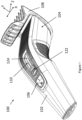
Fig. 1 shows an example personal grooming appliance; -
Fig. 2 shows a side view of a position setting assembly for the example grooming appliance; and -
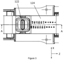
Fig. 3 shows a top view of the position setting assembly; -
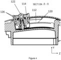
Fig. 4 shows a bi-section through the position setting assembly according to the line A-A inFig. 3 ; -
Fig. 5 shows an example of interlocking teeth for the position setting assembly. - With reference to
Figs. 1 to 5 , there is shown an examplepersonal grooming appliance 100. Thegrooming appliance 100 comprises a handle, or body, 102 for gripping and manipulating theappliance 100, anoperational head 104 configured to provide a grooming operation, and a function button 106 (e.g., an on-off button) for controlling the operational head 104 (and optionally any other functions of the appliance 100). - The
operational head 104 comprises at least oneadjustable part 108 having an adjustable position. That is, a part which may be at least partly displaced in an X direction, Y direction, or Z direction, or combination thereof, with respect to thebody 102 and/or any fixed component of theoperational head 104. - For example, the
operational head 104 may provide a hair clipping function, suitably comprising a cutter (not shown) configured to cut hair via a horizontal (X) motion the cutter. In this case the operational head may also comprise alength setting attachment 108 which is configured to be adjustable in the Z direction - i.e., a direction orthogonal to the X aligned motion of the cutter - either away from or towards theappliance 100. Suitably, by changing the position of thelength setting attachment 108, the length of hair that is cut may be changed. - It will be appreciated that the
operational head 104 may also comprise different adjustable components, including different length setting attachments, configured to vary position with respect to different orientations; for example a Y orientation or an X orientation. - The
appliance 100 comprises aposition setting assembly 110 configured to set a position (e.g., Z position) of theadjustable part 108. Theassembly 110 comprises aspine 112 and alocking element 114. - The
spine 112 comprises a first plurality of triangularshaped teeth 116. In the present example where theattachment 108 is moveable in the Z direction, thespine 112 may be arranged along a back line 118 of thehandle 102 so as to be substantially aligned with the direction of motion of theattachment 108. Put another way, thespine 112 is arranged centrally with respect to a width of thehandle 102 in the X direction. Suitably, in the present examples, thespine 112 may be taken to be substantially along the line A-A inFig. 3 . - The
locking element 114 comprises a second plurality of triangularshaped teeth 120 correspondingly shaped to the first plurality ofteeth 116. Suitably, the triangularshaped teeth spine 112 andlocking assembly 114 are configured to interlock. As shown, the first plurality ofteeth 116 preferably comprises a greater number if teeth than thesecond plurality 120. - The
locking element 114 comprises an actuator, or button, 122 configured to separate the first and second plurality of teeth by a translational motion when thebutton 122 is actuated. That is, by pushing down (in the Y direction) on thebutton 122, the second plurality ofteeth 120 are disengaged from the interlocking position with the first plurality ofteeth 116. Put another way, thelocking element 114 is configured to releasably engage with thespine 112. - When in the disengaged state, the
locking element 114 is free to slidably move with respect to thespine 112. Suitably, the body/handle 102 may comprise achannel 124, also aligned centrally with respect to a width ofhandle 102 in the X direction, in which thelocking assembly 114 may move. Moving thelocking element 114 suitably causes a corresponding movement in theadjustable part 108 so as to set the position of thepart 108. - Suitably, the
locking element 114 may also comprise abiasing element 126 which, when thebutton 122 is released, pushes upwards on thebutton 122 so as to return thelocking element 114 to a configuration in which the second plurality ofteeth 120 are (re)engaged with the first plurality ofteeth 116. Suitably the position of theadjustable part 108 is set and cannot be moved until thebutton 122 is actuated again. - In an alternative example, not shown, the
position setting assembly 110 may comprise an electric motor (not shown) configured to move thelocking element 114 with respect to thespine 112 when thelocking element 114 is disengaged from the spine by actuation of a suitable button. - Preferably, the triangularly
shaped teeth appliance 100 is suitably configured for a sub 2 mm step size which has thus far been unachievable mechanically. Further preferably, the triangular shaped teeth comprise arounded peak portion 130 so as to reduce stresses at the peak during interlock. - Moreover, the triangularly shaped teeth may be configured with a
height 132 of about 0.8 mm to about 0.95 mm, and abase width 134 of about 0.8 mm to 1 mm. It will be appreciated that thebase width 134 may be different to the peak-to-peak delta 128 due to a shape of the point of each tooth - e.g., due to any rounding, or flattening, of a tooth tip/peak; that is, the base may be measured between points on the triangular walls just before any shaping of a trough portion corresponding to the peak portion of the opposite set of teeth. In this way the teeth may be designed to readily fit with existing personal grooming appliances, so as to streamline manufacture of new devices and possibly allow the upgrade/retrofit of older devices. - In an example, the triangularly shaped teeth are scalene shaped. That is, each scalene shaped tooth in the first and second plurality of teeth may comprise a
short wall 136, along wall 138, and abase 134 of different lengths. Scalene shaped teeth are particularly advantageous, as they allow for a better distribution of force across the teeth and therefore better interlocking. - It will be appreciated that each of the
walls base 134 of each tooth does not engage. In a preferred example, theshort wall 136 of the first plurality of teeth 116 (i.e., the teeth of the spine 112) are oriented towards a head portion of the appliance 100 - i.e., towards theoperational head 104; that is, oriented with a positive Z facing. Arranging the scalene teeth in this orientation provides a stronger interlock able to better withstand forces pushing against the interlocking teeth when theappliance 100 is in use; that is, so that theteeth - While the invention has been illustrated and described in detail in the drawings and foregoing description, such illustration and description are to be considered illustrative or exemplary and not restrictive; the invention is not limited to the disclosed embodiments.
- Other variations to the disclosed embodiments can be understood and effected by those skilled in the art in practicing the claimed invention, from a study of the drawings, the disclosure, and the appended claims. In the claims, the word "comprising" does not exclude other elements or steps, and the indefinite article "a" or "an" does not exclude a plurality. A single processor or other unit may fulfil the functions of several items recited in the claims. The mere fact that certain measures are recited in mutually different dependent claims does not indicate that a combination of these measured cannot be used to advantage. Any reference signs in the claims should not be construed as limiting the scope.
Claims (13)
- A personal grooming appliance (100), comprising:an operational head (104) comprising apart (108) having an adjustable position;a position setting assembly (110) configured to set a position of the part, the assembly comprising a spine (112) and a locking element (114);wherein the locking element is configured to releasably engage with the spine, andwherein the spine and the locking element comprise a plurality of interlocking triangularly shaped teeth (116, 120).
- The appliance of claim 1, wherein the triangularly shaped teeth are configured with a peak to peak delta (128) of about 0.5 mm to about 1.5 mm
- The appliance of claim 2, wherein the triangularly shaped teeth are configured with a peak to peak delta of about 1 mm
- The appliance of any preceding claim, wherein the triangularly shaped teeth are configured with a height (132) of about 0.8 mm to about 0.95 mm
- The appliance of any preceding claim, wherein the triangularly shaped teeth are configured with a base width (134) of about 0.8 mm to 1 mm
- The appliance of any preceding claim, wherein each tooth of the plurality of triangular shaped teeth comprises a rounded peak (130).
- The appliance of any preceding claim, wherein the triangularly shaped teeth are scalene shaped.
- The appliance of claim 7, wherein each scalene shaped tooth in the plurality of triangularly shaped teeth comprises a short engagement wall (136) and a long engagement wall (138), and wherein the short engagement wall of each tooth on the spine is oriented towards a head portion of the personal grooming appliance.
- The appliance of any preceding claim, wherein the spine is arranged centrally with respect to a width of the personal grooming appliance.
- The appliance of any preceding claim, wherein the position setting assembly comprises a button (122) configured to release the locking element from engagement with the spine when the button is actuated.
- The appliance of any preceding claim, wherein the locking element is configured to slidably move (124) with respect to the spine when the locking element is disengaged from the spine.
- The appliance of any preceding claim, wherein the position setting assembly comprises an electric motor configured to move the locking element with respect to the spine when the locking element is disengaged from the spine.
- The appliance of any preceding claim, wherein the operational head comprises a hair clipper.
Priority Applications (4)
| Application Number | Priority Date | Filing Date | Title |
|---|---|---|---|
| EP23210257.4A EP4556180A1 (en) | 2023-11-16 | 2023-11-16 | Personal grooming appliance |
| PCT/EP2024/081491 WO2025103866A1 (en) | 2023-11-16 | 2024-11-07 | Personal grooming appliance |
| CN202411628195.4A CN120002723A (en) | 2023-11-16 | 2024-11-14 | Personal Grooming Equipment |
| CN202422780800.1U CN223477697U (en) | 2023-11-16 | 2024-11-14 | Personal grooming device |
Applications Claiming Priority (1)
| Application Number | Priority Date | Filing Date | Title |
|---|---|---|---|
| EP23210257.4A EP4556180A1 (en) | 2023-11-16 | 2023-11-16 | Personal grooming appliance |
Publications (1)
| Publication Number | Publication Date |
|---|---|
| EP4556180A1 true EP4556180A1 (en) | 2025-05-21 |
Family
ID=88837397
Family Applications (1)
| Application Number | Title | Priority Date | Filing Date |
|---|---|---|---|
| EP23210257.4A Withdrawn EP4556180A1 (en) | 2023-11-16 | 2023-11-16 | Personal grooming appliance |
Country Status (3)
| Country | Link |
|---|---|
| EP (1) | EP4556180A1 (en) |
| CN (2) | CN120002723A (en) |
| WO (1) | WO2025103866A1 (en) |
Citations (4)
| Publication number | Priority date | Publication date | Assignee | Title |
|---|---|---|---|---|
| US2941293A (en) * | 1958-12-17 | 1960-06-21 | Chester J Mazzoni | Hair clipper |
| WO2014090429A1 (en) | 2012-12-10 | 2014-06-19 | Koninkluke Philips N.V. | A hair trimming device |
| CN109623886A (en) * | 2018-11-30 | 2019-04-16 | 上海奔腾电工有限公司 | A kind of limiting comb adjusts and locking device |
| EP4035851A1 (en) * | 2021-02-02 | 2022-08-03 | Koninklijke Philips N.V. | A comb attachment and a kit |
-
2023
- 2023-11-16 EP EP23210257.4A patent/EP4556180A1/en not_active Withdrawn
-
2024
- 2024-11-07 WO PCT/EP2024/081491 patent/WO2025103866A1/en active Pending
- 2024-11-14 CN CN202411628195.4A patent/CN120002723A/en active Pending
- 2024-11-14 CN CN202422780800.1U patent/CN223477697U/en active Active
Patent Citations (4)
| Publication number | Priority date | Publication date | Assignee | Title |
|---|---|---|---|---|
| US2941293A (en) * | 1958-12-17 | 1960-06-21 | Chester J Mazzoni | Hair clipper |
| WO2014090429A1 (en) | 2012-12-10 | 2014-06-19 | Koninkluke Philips N.V. | A hair trimming device |
| CN109623886A (en) * | 2018-11-30 | 2019-04-16 | 上海奔腾电工有限公司 | A kind of limiting comb adjusts and locking device |
| EP4035851A1 (en) * | 2021-02-02 | 2022-08-03 | Koninklijke Philips N.V. | A comb attachment and a kit |
Also Published As
| Publication number | Publication date |
|---|---|
| CN223477697U (en) | 2025-10-28 |
| CN120002723A (en) | 2025-05-16 |
| WO2025103866A1 (en) | 2025-05-22 |
Similar Documents
| Publication | Publication Date | Title |
|---|---|---|
| US11858153B2 (en) | Spacing comb and hair cutting appliance | |
| EP2747961B1 (en) | Variable cutting length hair clipping system | |
| EP3215322B1 (en) | Hair clipping device | |
| EP3038800B1 (en) | Hair clipping device | |
| EP3253541B1 (en) | Cutting head and hair cutting appliance | |
| EP3225369B1 (en) | Comb attachment for hair clippers | |
| EP3126105B1 (en) | Hair clipping device. | |
| EP2875916A1 (en) | Mounting unit and hair cutting appliance | |
| JP2009050496A (en) | Clippers | |
| CN103945995A (en) | Skin guard for hair trimmer | |
| US20160151923A1 (en) | Hair clipper and method of forming the same | |
| EP4556180A1 (en) | Personal grooming appliance | |
| EP3160692B1 (en) | An actuating mechanism for controlling the cutting length of a hair trimmer | |
| EP2892696B1 (en) | Hair clipping device | |
| EP4126480B1 (en) | A cutting unit | |
| CN114981049A (en) | Accessory of electric hair cutting device | |
| JP2011045745A (en) | Hair clippers |
Legal Events
| Date | Code | Title | Description |
|---|---|---|---|
| PUAI | Public reference made under article 153(3) epc to a published international application that has entered the european phase |
Free format text: ORIGINAL CODE: 0009012 |
|
| STAA | Information on the status of an ep patent application or granted ep patent |
Free format text: STATUS: THE APPLICATION HAS BEEN PUBLISHED |
|
| AK | Designated contracting states |
Kind code of ref document: A1 Designated state(s): AL AT BE BG CH CY CZ DE DK EE ES FI FR GB GR HR HU IE IS IT LI LT LU LV MC ME MK MT NL NO PL PT RO RS SE SI SK SM TR |
|
| STAA | Information on the status of an ep patent application or granted ep patent |
Free format text: STATUS: THE APPLICATION IS DEEMED TO BE WITHDRAWN |
|
| 18D | Application deemed to be withdrawn |
Effective date: 20251122 |