EP4556119A1 - Liquid distribution system for a fluidic chip - Google Patents
Liquid distribution system for a fluidic chip Download PDFInfo
- Publication number
- EP4556119A1 EP4556119A1 EP23307007.7A EP23307007A EP4556119A1 EP 4556119 A1 EP4556119 A1 EP 4556119A1 EP 23307007 A EP23307007 A EP 23307007A EP 4556119 A1 EP4556119 A1 EP 4556119A1
- Authority
- EP
- European Patent Office
- Prior art keywords
- liquid
- layer
- distribution system
- feeding
- channel
- Prior art date
- Legal status (The legal status is an assumption and is not a legal conclusion. Google has not performed a legal analysis and makes no representation as to the accuracy of the status listed.)
- Withdrawn
Links
Images




Classifications
-
- B—PERFORMING OPERATIONS; TRANSPORTING
- B01—PHYSICAL OR CHEMICAL PROCESSES OR APPARATUS IN GENERAL
- B01L—CHEMICAL OR PHYSICAL LABORATORY APPARATUS FOR GENERAL USE
- B01L3/00—Containers or dishes for laboratory use, e.g. laboratory glassware; Droppers
- B01L3/50—Containers for the purpose of retaining a material to be analysed, e.g. test tubes
- B01L3/502—Containers for the purpose of retaining a material to be analysed, e.g. test tubes with fluid transport, e.g. in multi-compartment structures
- B01L3/5027—Containers for the purpose of retaining a material to be analysed, e.g. test tubes with fluid transport, e.g. in multi-compartment structures by integrated microfluidic structures, i.e. dimensions of channels and chambers are such that surface tension forces are important, e.g. lab-on-a-chip
- B01L3/502715—Containers for the purpose of retaining a material to be analysed, e.g. test tubes with fluid transport, e.g. in multi-compartment structures by integrated microfluidic structures, i.e. dimensions of channels and chambers are such that surface tension forces are important, e.g. lab-on-a-chip characterised by interfacing components, e.g. fluidic, electrical, optical or mechanical interfaces
-
- B—PERFORMING OPERATIONS; TRANSPORTING
- B01—PHYSICAL OR CHEMICAL PROCESSES OR APPARATUS IN GENERAL
- B01L—CHEMICAL OR PHYSICAL LABORATORY APPARATUS FOR GENERAL USE
- B01L3/00—Containers or dishes for laboratory use, e.g. laboratory glassware; Droppers
- B01L3/50—Containers for the purpose of retaining a material to be analysed, e.g. test tubes
- B01L3/502—Containers for the purpose of retaining a material to be analysed, e.g. test tubes with fluid transport, e.g. in multi-compartment structures
- B01L3/5027—Containers for the purpose of retaining a material to be analysed, e.g. test tubes with fluid transport, e.g. in multi-compartment structures by integrated microfluidic structures, i.e. dimensions of channels and chambers are such that surface tension forces are important, e.g. lab-on-a-chip
- B01L3/502738—Containers for the purpose of retaining a material to be analysed, e.g. test tubes with fluid transport, e.g. in multi-compartment structures by integrated microfluidic structures, i.e. dimensions of channels and chambers are such that surface tension forces are important, e.g. lab-on-a-chip characterised by integrated valves
-
- B—PERFORMING OPERATIONS; TRANSPORTING
- B01—PHYSICAL OR CHEMICAL PROCESSES OR APPARATUS IN GENERAL
- B01L—CHEMICAL OR PHYSICAL LABORATORY APPARATUS FOR GENERAL USE
- B01L2200/00—Solutions for specific problems relating to chemical or physical laboratory apparatus
- B01L2200/02—Adapting objects or devices to another
- B01L2200/026—Fluid interfacing between devices or objects, e.g. connectors, inlet details
- B01L2200/027—Fluid interfacing between devices or objects, e.g. connectors, inlet details for microfluidic devices
-
- B—PERFORMING OPERATIONS; TRANSPORTING
- B01—PHYSICAL OR CHEMICAL PROCESSES OR APPARATUS IN GENERAL
- B01L—CHEMICAL OR PHYSICAL LABORATORY APPARATUS FOR GENERAL USE
- B01L2200/00—Solutions for specific problems relating to chemical or physical laboratory apparatus
- B01L2200/02—Adapting objects or devices to another
- B01L2200/028—Modular arrangements
-
- B—PERFORMING OPERATIONS; TRANSPORTING
- B01—PHYSICAL OR CHEMICAL PROCESSES OR APPARATUS IN GENERAL
- B01L—CHEMICAL OR PHYSICAL LABORATORY APPARATUS FOR GENERAL USE
- B01L2300/00—Additional constructional details
- B01L2300/08—Geometry, shape and general structure
- B01L2300/0809—Geometry, shape and general structure rectangular shaped
- B01L2300/0816—Cards, e.g. flat sample carriers usually with flow in two horizontal directions
-
- B—PERFORMING OPERATIONS; TRANSPORTING
- B01—PHYSICAL OR CHEMICAL PROCESSES OR APPARATUS IN GENERAL
- B01L—CHEMICAL OR PHYSICAL LABORATORY APPARATUS FOR GENERAL USE
- B01L2300/00—Additional constructional details
- B01L2300/08—Geometry, shape and general structure
- B01L2300/0861—Configuration of multiple channels and/or chambers in a single devices
- B01L2300/0864—Configuration of multiple channels and/or chambers in a single devices comprising only one inlet and multiple receiving wells, e.g. for separation, splitting
-
- B—PERFORMING OPERATIONS; TRANSPORTING
- B01—PHYSICAL OR CHEMICAL PROCESSES OR APPARATUS IN GENERAL
- B01L—CHEMICAL OR PHYSICAL LABORATORY APPARATUS FOR GENERAL USE
- B01L2300/00—Additional constructional details
- B01L2300/08—Geometry, shape and general structure
- B01L2300/0861—Configuration of multiple channels and/or chambers in a single devices
- B01L2300/0867—Multiple inlets and one sample wells, e.g. mixing, dilution
-
- B—PERFORMING OPERATIONS; TRANSPORTING
- B01—PHYSICAL OR CHEMICAL PROCESSES OR APPARATUS IN GENERAL
- B01L—CHEMICAL OR PHYSICAL LABORATORY APPARATUS FOR GENERAL USE
- B01L2300/00—Additional constructional details
- B01L2300/08—Geometry, shape and general structure
- B01L2300/0887—Laminated structure
-
- B—PERFORMING OPERATIONS; TRANSPORTING
- B01—PHYSICAL OR CHEMICAL PROCESSES OR APPARATUS IN GENERAL
- B01L—CHEMICAL OR PHYSICAL LABORATORY APPARATUS FOR GENERAL USE
- B01L2400/00—Moving or stopping fluids
- B01L2400/04—Moving fluids with specific forces or mechanical means
- B01L2400/0475—Moving fluids with specific forces or mechanical means specific mechanical means and fluid pressure
- B01L2400/0487—Moving fluids with specific forces or mechanical means specific mechanical means and fluid pressure fluid pressure, pneumatics
-
- B—PERFORMING OPERATIONS; TRANSPORTING
- B01—PHYSICAL OR CHEMICAL PROCESSES OR APPARATUS IN GENERAL
- B01L—CHEMICAL OR PHYSICAL LABORATORY APPARATUS FOR GENERAL USE
- B01L2400/00—Moving or stopping fluids
- B01L2400/06—Valves, specific forms thereof
- B01L2400/0633—Valves, specific forms thereof with moving parts
- B01L2400/0655—Valves, specific forms thereof with moving parts pinch valves
-
- B—PERFORMING OPERATIONS; TRANSPORTING
- B01—PHYSICAL OR CHEMICAL PROCESSES OR APPARATUS IN GENERAL
- B01L—CHEMICAL OR PHYSICAL LABORATORY APPARATUS FOR GENERAL USE
- B01L3/00—Containers or dishes for laboratory use, e.g. laboratory glassware; Droppers
- B01L3/50—Containers for the purpose of retaining a material to be analysed, e.g. test tubes
- B01L3/502—Containers for the purpose of retaining a material to be analysed, e.g. test tubes with fluid transport, e.g. in multi-compartment structures
- B01L3/5025—Containers for the purpose of retaining a material to be analysed, e.g. test tubes with fluid transport, e.g. in multi-compartment structures for parallel transport of multiple samples
-
- B—PERFORMING OPERATIONS; TRANSPORTING
- B01—PHYSICAL OR CHEMICAL PROCESSES OR APPARATUS IN GENERAL
- B01L—CHEMICAL OR PHYSICAL LABORATORY APPARATUS FOR GENERAL USE
- B01L3/00—Containers or dishes for laboratory use, e.g. laboratory glassware; Droppers
- B01L3/50—Containers for the purpose of retaining a material to be analysed, e.g. test tubes
- B01L3/508—Rigid containers without fluid transport within
- B01L3/5085—Rigid containers without fluid transport within for multiple samples, e.g. microtitration plates
- B01L3/50853—Rigid containers without fluid transport within for multiple samples, e.g. microtitration plates with covers or lids
-
- B—PERFORMING OPERATIONS; TRANSPORTING
- B01—PHYSICAL OR CHEMICAL PROCESSES OR APPARATUS IN GENERAL
- B01L—CHEMICAL OR PHYSICAL LABORATORY APPARATUS FOR GENERAL USE
- B01L9/00—Supporting devices; Holding devices
- B01L9/52—Supports specially adapted for flat sample carriers, e.g. for plates, slides, chips
- B01L9/527—Supports specially adapted for flat sample carriers, e.g. for plates, slides, chips for microfluidic devices, e.g. used for lab-on-a-chip
Definitions
- the present invention relates to a liquid distribution system for a fluidic chip, an assembly comprising this liquid distribution system and a method of feeding liquid to a fluidic chip using this liquid distribution system.
- An organ-on-a-chip is a microfluidic cell culture device designed to simulate the mechanical environment and study the physiological response of one or more organs.
- these devices enable toxicology, drug development or personalized medicine studies to be carried out without animal experimentation.
- Document WO 2017/035484 discloses a perfusion manifold assembly for putting a microfluidic device such as an organ-on-a-chip in fluidic communication with a fluid source or another microfluidic device.
- This technology does not offer the possibility of sequential distribution, does not seem compatible with conventional optical systems, nor with conventional chips made for example of polydimethylsiloxane.
- Document US 2018/0169656 discloses a microfluidic plate comprising a plurality of microfluidic networks and inlets providing access to the microfluidic networks.
- Each microfluidic network comprises a capillary pressure barrier.
- Each inlet is formed by an inlet chamber having a bottom surface. This technology does not offer the possibility of sequential distribution, does not seem compatible with conventional chips made for example of polydimethylsiloxane and does not offer a precise control of flowrate.
- Document EP 3705564 discloses a device and method to obtain a controlled medium perfusion and drug injection/removal into standard cell culture dishes (Petri dishes). This technology does not offer the possibility of sequential distribution and does not seem compatible with conventional chips made for example of polydimethylsiloxane.
- the invention relates to the following items.
- a liquid distribution system for fluidic chips comprising:
- Item 2 The liquid distribution system of item 1, wherein the liquid feeding ports are arranged in an array of rows and columns; and/or the liquid collecting ports are arranged in an array of rows and columns.
- Item 3 The liquid distribution system of item 1 or 2, wherein :
- Item 4 The liquid distribution system of item 3, comprising:
- Item 5 The liquid distribution system of any one of items 1 to 4, wherein the valves comprise:
- Item 6 The liquid distribution system of any one of items 1 to 5, wherein the control module is a pneumatic control module, the valves are membrane valves and the pneumatic control module comprises:
- Item 7 The liquid distribution system of item 6, comprising a single deformable membrane fixed onto the liquid distribution layer.
- Item 8 The liquid distribution system of item 6 or 7, wherein the feeding channel and/or collecting channel in the liquid distribution layer comprise a plurality of protrusions against which respective membrane valves press to obstruct fluid communication in said feeding channel and/or collecting channel.
- Item 9 The liquid distribution system of any one of items 6 to 8, wherein at least a portion of the gas channels fluidically connects a gas inlet to a single membrane valve.
- Item 10 The liquid distribution system of any one of items 6 to 9, wherein the pneumatic control module comprises at least one layer which comprises gas channels, and one connecting layer which comprises connecting holes interposed between the gas channels and the membrane valves.
- Item 11 The liquid distribution system of any one of items 6 to 10, wherein the pneumatic control module comprises at least a first layer comprising a first group of gas channels, and a second layer comprising a second group of gas channels; wherein, preferably, the first group of gas channels is fluidically connected with the second group of membrane valves, and the second group of gas channels is fluidically connected with the first group and third group of membrane valves.
- Item 14 The assembly of item 13, wherein the gas pressure controller is configured for selectively applying a low pressure level or a high pressure level in each gas line.
- Item 15 The assembly of any one of items 12 to 14, comprising at least one liquid delivery device, preferably a liquid delivery device associated with each liquid reservoir.
- Item 16 The assembly of any one of items 12 to 15, further comprising the one or more fluidic chips coupled to the liquid distribution system.
- each liquid feeding port of the liquid distribution system is directly coupled to a fluidic chip inlet, optionally via a gasket, and each liquid collecting port of the liquid distribution system is directly coupled to a fluidic chip outlet, optionally via a gasket.
- Item 18 The assembly of item 16 or 17, wherein the or each fluidic chip comprises a plurality of chambers, each chamber comprising one of the fluidic chip inlets and one of the fluidic chip outlets.
- Item 19 The assembly of any one of items 16 to 18, wherein the one or more fluidic chips are placed on an optical system, preferably a microscope.
- Item 20 A method of feeding liquid to one or more fluidic chips comprising a plurality of fluidic chip inlets and fluidic chip outlets, the method comprising:
- Item 21 The method of item 20, comprising:
- Item 22 The method of item 20 or 21, wherein the liquid distribution system is according to any one of items 6 to 11, and wherein the valves are actuated by controlling pressure at each gas inlet of the pneumatic control module.
- Item 23 The method of item 22, wherein the controlled pressure is selected from two pressure levels, namely a low pressure level and a high pressure level.
- Item 24 The method of any one of items 20 to 23, wherein connecting the liquid distribution system to the one or more fluidic chips comprises directly coupling each liquid feeding port of the liquid distribution system to a fluidic chip inlet, optionally via a gasket, and directly coupling each liquid collecting port of the liquid distribution system to a fluidic chip outlet, optionally via a gasket.
- the invention addresses the need expressed above.
- the invention provides a liquid distribution system:
- Liquid may be caused to flow from various liquid reservoirs to the fluidic chip(s) via the liquid distribution layer, according to a variety of possible flow paths which are established by actuating selected valves in the pneumatic control module.
- the liquid distribution system 1 can be mechanically coupled to a fluid source system 2 via a coupling 7 to form an assembly.
- the fluid source system 2 may comprise a plurality of liquid reservoirs 21 and at least one liquid collector 22.
- the liquid reservoirs 21 are containers which contain liquid media (preferably, different liquid media) adapted to be fed to the liquid distribution system 1, while the liquid collector 22 is a container adapted to collect liquid medium from the liquid distribution system 1.
- the liquid distribution system 1 may also be mechanically coupled to one or more fluidic chips 3 so as to feed liquid (preferably the different liquid media from the liquid reservoirs 21) to the fluidic chip(s) 3 and to collect liquid medium from the fluidic chip(s) 3 and make it flow back to the liquid collector 22 in the fluid source system 2.
- liquid preferably the different liquid media from the liquid reservoirs 21
- the fluidic chip(s) 3 may be placed on an optical system so as to be able to visualize the interior of the fluidic chip(s) 3 during use.
- the or each fluidic chip 3 may be substantially in the shape of a plate having two main substantially planar faces; one main face is in contact with the liquid distribution system 1, whereas the opposite main face may be put in contact with a glass slide 4.
- the glass slide 4 may rest on a support 5, and a microscope objective 6 may face the glass slide.
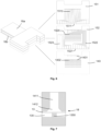
- FIG 2 shows in more detail an example of the liquid distribution system 1 coupled with a fluidic chip 3 resting on a glass slide 4.
- the liquid distribution system 1 may comprise a liquid connection module 17, a liquid distribution layer 12, a control module (which may comprise a gasket layer 142, a membrane 13, a fluidic connecting layer 141, a pneumatic connecting layer 143 and a pneumatic layer 15) and a pneumatic input module 16 as will be described in more detail below.
- the coupling 7 of Figure 1 may comprise the liquid connection module 17 and the pneumatic input module 16.
- the liquid distribution system 1, fluidic chip(s) 3 and glass slide 4 may rest and be partially enclosed in the support 5, which may for example be in a conventional 96-well format.
- a lid 9 may optionally cooperate with the support 5 so that, in an open position, the glass slide 4, fluidic chip 3 and liquid distribution system 1 may be placed on the support 5 or removed from the support 5, and, in a closed position, the fluidic chip 3 and liquid distribution system 1 may be enclosed in an enclosure defined by the support 5, glass slide 4 and lid 9.
- Respective openings may be provided between the support 5 and the lid 9 so that the liquid connection module 17 and pneumatic input module 16 can be positioned through the enclosure.
- a gas feeding connection 8 may be provided either on the lid 9 or, as shown, on the support 5, in order to control the composition of the atmosphere surrounding the fluidic chip(s) 3.
- liquid distribution system 1, fluidic chip(s) 3 and fluid source system 2 More details will be provided below on the liquid distribution system 1, fluidic chip(s) 3 and fluid source system 2.
- the liquid distribution system 1 may comprise an assembly of layers.
- Each layer may be substantially in the shape of a plate (notwithstanding any hole, channel, or protrusion, as will be described in more detail below).
- each layer may comprise two main faces, each main face being planar, the two main faces being preferably parallel to each other.
- One main face of each layer in the assembly may be fixed to one main face of another, adjacent layer.
- Each layer may comprise a number of side faces joining the two main faces together.
- the side faces may also be planar.
- the side faces may be perpendicular to the main faces.
- the total surface area of the side faces may be less than the total surface area of the main faces, preferably less than 10 times the total surface area of the main faces, or less than 100 times the total surface area of the main faces.
- the perimeter of the main faces may be a rectangle, so that the layer is substantially parallelepiped-shaped.
- the perimeter of the main faces may be another polygon, such as an octagon (corresponding to a rectangle with a rectangular cutout).
- the liquid distribution system 1 notably comprises a liquid distribution layer 12, and a control module 11.
- the control module 11 itself may be made of one or more layers.
- the main function of the liquid distribution layer 12 is to channel liquid to and from the fluidic chip(s) 3.
- the main function of the control module 11 is to selectively open (i.e. establish) or obstruct fluid communication within the liquid distribution layer 12 owing to a plurality of valves, so as to selectively direct liquid from a desired source to a desired chamber of the fluidic chip(s), and to collect liquid from the fluidic chip(s).
- fluid communication means an uninterrupted flow path for the fluid.
- two elements are said to be “fluidically connected”, it means that fluid communication can be established from one element to the other (provided, if necessary, that one or more valves be open).
- the liquid distribution layer 12 comprises a plurality of liquid inlets 121.
- These liquid inlets are intended to receive liquid from an external source.
- a different liquid medium can be fed to each liquid inlet.
- the liquid distribution layer 12 further comprises a plurality of liquid feeding ports 123.
- the liquid feeding ports 123 are intended to feed liquid to a or the fluidic chip 3. More precisely, each liquid feeding port 123 may be coupled to a respective fluidic chip inlet as will be described in more detail below.
- the liquid feeding ports 123 may be arranged as a matrix of rows 128 and columns 129. In the illustration, there are 6 rows and 4 columns. But the number of columns can vary for example from 1 to 10, preferably from 2 to 8, more preferably from 3 to 6. And the number of rows can vary for example from 1 to 12, preferably from 3 to 10, more preferably from 4 to 8.
- the liquid feeding ports 123 may be geometrically aligned in each row, respectively in each column. Alternatively, liquid feeding ports 123 may be staggered in each row and/or in each column. In the illustrated example, the liquid feeding ports 123 are geometrically aligned in each row 128, but are not all geometrically aligned (are staggered) in each column 129.
- At least one feeding channel 125a, 125b, 125c fluidically connects each liquid inlet 121 to the liquid feeding ports 123. It is possible to have a plurality of feeding channels, each feeding channel separately fluidically connecting one liquid inlet 121 to one liquid feeding port 123, or to a group of liquid feeding ports 123. In this case, each liquid feeding port 123 can be for example fed with liquid from only one liquid inlet 121.
- a single (branched) feeding channel fluidically connects all liquid inlets 121 to all liquid feeding ports 123.
- each liquid feeding port 123 can be fed with liquid from any liquid inlet 121.
- the single feeding channel may in particular comprise a common portion 125a fluidically connected to the plurality of liquid inlets 121 (namely, to all liquid inlets 121).
- the single feeding channel may further comprise a plurality of branch portions 125b, each branch portion 125b being fluidically connected to the common portion 125a. Each branch portion 125b branches out from the common portion 125a. Each branch portion 125b may be configured to feed liquid to all liquid feeding ports 123 of the same column. In the illustration, there are four branch portions 125b.
- the common portion 125a may for example branch out into two intermediate segments, each intermediate segment then branching out into two branch portions 125b, as shown.
- the single feeding channel may further comprise a plurality of subbranch portions 125c.
- Each subbranch portion 125c branches out from a branch portion 125b.
- Each subbranch portion 125c may be configured to feed liquid to only one liquid feeding port 123.
- Each branch portion 125b may be fluidically connected to a plurality of subbranch portions 125c (one subbranch portion 125c per row of liquid feeding ports).
- the liquid distribution layer 12 further comprises a plurality of liquid collecting ports 124.
- the liquid feeding ports 124 are intended to collect liquid from the or a fluidic chip 3. More precisely, each liquid collecting port 124 may be coupled to a respective fluidic chip outlet as will be described in more detail below.
- the number of liquid collecting ports 124 is the same as the number of liquid feeding ports 123, and the liquid feeding ports 123 and liquid collecting ports 124 are arranged in pairs. In use, liquid is therefore fed to the or a fluidic chip via at least one liquid feeding port 123 and simultaneously collected from said fluidic chip via the at least one corresponding liquid collecting port 124 in the pair.
- liquid feeding ports 123 can be paired with one liquid collecting port 124, or two or more liquid collecting ports 124 can be paired with one liquid feeding port 123.
- the liquid distribution layer 12 further comprises at least one liquid outlet 122.
- the liquid outlet(s) is(are) intended to withdraw liquid from the liquid distribution layer 12.
- the liquid outlet(s) 122 is(are) fluidically connected to all liquid collecting ports 124.
- At least one collecting channel 126a, 126b, 126c fluidically connects the liquid outlet(s) 122 to the liquid collecting ports 124. It is possible to have a plurality of collecting channels, each collecting channel separately fluidically connecting a liquid outlet 122 to one liquid collecting port 124, or to a group of liquid collecting ports 124.
- a single (branched) collecting channel fluidically connects a single liquid outlet 122 to all liquid collecting ports 124.
- the liquid collected from all liquid collecting ports 124 is directed to the same liquid outlet 122.
- the single collecting channel may in particular comprise a common portion 126a fluidically connected to the liquid outlet 122.
- the single collecting channel may further comprise a plurality of branch portions 126b, each branch portion 126b being fluidically connected to the common portion 126a. Each branch portion 126b branches out from the common portion 126a. Each branch portion 126b may be configured to collect liquid from all liquid collecting ports 124 of the same column. In the illustration, there are four branch portions 126b.
- the common portion 126a may for example branch out into two intermediate segments, each intermediate segment then branching out into two branch portions 126b.
- the single collecting channel may further comprise a plurality of subbranch portions 126c.
- Each subbranch portion 126c branches out from a branch portion 126b.
- Each subbranch portion 126c may be configured to collect liquid from only one liquid collecting port 124.
- Each branch portion 126b may be fluidically connected to a plurality of subbranch portions 126c (one subbranch portion 126c per row of liquid collecting ports).
- bypass channels 127 fluidically connecting the feeding channel 125a, 125b, 125c to the collecting channel 126a, 126b, 126c directly (i.e. not via a fluidic chip) may be provided. More precisely, a bypass channel 127 may fluidically connect each branch portion 125b of the feeding channel to a respective branch portion 126b of the collecting channel. There may thus be one bypass 127 channel per column 129 (or one bypass channel 127 per row 128 if the alternative arrangement is used).
- the liquid distribution layer 12 may be overall in the shape of a plate having two main substantially planar faces. A first main face is in contact with the control module 11 and in particular with the membrane 13 of the control module 11. The opposite, second main face is intended to be in contact with the fluidic chip(s) 3.
- the liquid distribution layer 12 may have a thickness from 1 mm to 20 mm, preferably from 3 mm to 4 mm.
- the thickness direction corresponds to the direction which is orthogonal to the main faces of the plate.
- the feeding channel(s) 125 and collecting channel(s) 126 may be provided as grooves on the first main face of the liquid distribution layer 12.
- Each groove may have a depth (in the thickness direction) of from 20 ⁇ m to 2 mm, preferably from 100 ⁇ m to 750 ⁇ m.
- Each groove may have a width (perpendicular to the thickness direction and perpendicular to the longitudinal direction of the channel) of from 20 ⁇ m to 2 mm, preferably from 100 ⁇ m to 750 ⁇ m.
- Each liquid feeding port 123 and liquid collecting port 124 may comprise a protrusion 1231, 1241 on the second main face and a through hole 1232, 1242 ensuring a fluidic connection to the respective feeding channel 125 or collecting channel 126.
- the liquid distribution layer 12 may be made of any biocompatible hard materials such as polycarbonate, polymethylmethacrylate, polyoxymethylene, cyclic olefin polymers, cyclic olefin copolymers, polytetrafluoroethylene, polyetherimide, and metal alloys.
- the liquid distribution layer 12 may be manufactured for example by machining (such as drilling, engraving, carving) a plate of solid material, by injection molding or by additive manufacturing such as 3D-printing.
- control module 11 may comprise a plurality of valves 18, each valve being configured to open or obstruct fluid communication in the feeding channel 125 or in the collecting channel 126 of the liquid distribution layer 12, the control module 11 being configured to selectively establish fluid communication between any of the liquid inlets 121 and any of the liquid feeding ports 123 (and between any of the liquid collecting ports 124 and a or the liquid outlet 122).
- control module 11 which is a pneumatic control module, i . e . a control module wherein the valves 18 are actuated by controlling gas pressure.
- control module 11 it is also possible for the control module 11 to be designed in a different manner.
- piezoelectrically actuated valves can also be employed.
- valves 18 are membrane valves and a single membrane 13 is used to make all membrane valves.
- membrane valves 18 it is also possible for the membrane valves 18 to be based on more than one membranes.
- each membrane valve can have its own dedicated membrane.
- the control module 11 may thus comprise a layer which is a membrane 13 in contact with the first main face of the distribution layer 12, a connecting layer 14 in contact with the membrane 13 (on the main face of the membrane 13 opposite the main face in contact with the first main face of the distribution layer 12) and a pneumatic layer 15 in contact with the connecting layer 14 (on the main face of the connecting layer 14 opposite the main face which is in contact with the membrane 13).
- the membrane 13 may have a thickness from 20 ⁇ m to 1 mm, preferably from 50 ⁇ m to 500 ⁇ m.
- the membrane 13 may be made of any biocompatible soft materials such as silicone based materials (e.g., polydimethylsiloxane), fluoroelastomers (such as FKM, FFKM%) or rubbers (such as NBR, EPDM).
- the pneumatic layer 15 may comprise a plurality of gas inlets 1511, 1521.
- the pneumatic layer 15 may comprise a plurality of gas channels 1512, 1522, 1523, wherein each gas channel 1512, 1522, 1523 fluidically connects a gas inlet 1511, 1521 to at least one membrane valve 18.
- a gas channel 1512, 1522 may fluidically connect a gas inlet 1511, 1521 to a single membrane valve 18, while in other cases a gas channel 1523 may fluidically connect a gas inlet 1521 to a plurality of membrane valves 18.
- the connecting layer 14 may comprise a plurality of connecting holes 1431, 1421, 1411 interposed between (and fluidically connecting) the gas channels 1512, 1522, 1523 and the membrane valves 18.
- Each of the pneumatic layer 15 and connecting layer 14 may itself be a stack of two or more layers.
- the pneumatic layer 15 may comprise a first layer 151 and a second layer 152.
- Each of the first layer 151 and second layer 152 may be substantially planar.
- Each of the first layer 151 and second layer 152 may have a thickness from 1 mm to 20 mm, preferably from 3 mm to 4 mm.
- Each of the first layer 151 and second layer 152 may be made of any biocompatible hard materials such as polycarbonate, polymethylmethacrylate, polyoxymethylene, cyclic olefin polymers, cyclic olefin copolymers polytetrafluoroethylene, polyetherimide, and metal alloys.
- Each of the first layer 151 and second layer 152 may comprise gas channels 1512, 1522, 1523.
- the gas channels 1512, 1522, 1523 may be formed as grooves on one main face of each of the first layer 151 and second layer 152.
- Each groove may have a depth of from 20 ⁇ m to 2 mm, preferably from 100 ⁇ m to 750 ⁇ m .
- Each groove may have a width of from 20 ⁇ m to 2 mm, preferably from 100 ⁇ m to 750 ⁇ m.
- each gas inlet 1511, 1521 is simply formed by one end of a respective gas channel 1512, 1522, 1523 on one side face of the respective layer 151, 152.
- the pneumatic input module 16 may comprise a first pneumatic input 16a connected to all gas inlets 1511 of the first layer 151 and a second pneumatic input 16b connected to all gas inlets 1521 of the second layer 152.
- the connection may be substantially leaktight and may be performed for example by clamping .
- Each pneumatic input 16a, 16b may contain a number of parallel gas channels or tubes.
- a main face of the second layer 152 may be in contact with a main face of the connecting layer 14.
- a main face of the first layer 151 may be in contact with the other main face of the second layer 152.
- the gas channels 1512 in the first layer 151 may be provided on the main face of the first layer 151 which is in contact with the second layer 152.
- the gas channels 1522, 1523 in the second layer 152 may be provided on the main face of the second layer 152 which is in contact with the connecting layer 14.
- the first layer 151 may comprise a first group of gas channels 1512.
- the second layer 152 may comprise a second group of gas channels 1522 and a third group of gas channels 1523. These groups of gas channels may have different functions, as will be further explained below.
- the second layer 152 may comprise holes 1524 running through the entire thickness thereof and ensuring fluidic connection between the gas channels 1512 of the first layer 151 and the respective membrane valves 18.
- Each of the first layer 151 and second layer 152 may be manufactured for example by machining (such as drilling, engraving, carving) a plate of solid material, by injection molding or by additive manufacturing such as 3D-printing.
- the pneumatic layer 15 can be made of a single-piece layer, in which case all gas channels may be located on the main face of the pneumatic layer 15 in contact with the connecting layer 14.
- the pneumatic layer 15 can comprise a stack of more than two layers, such as three layers, each such layer comprising gas channels, formed on a main face of the layer facing another layer of the pneumatic layer or facing the connecting layer 14, and corresponding gas inlets.
- the connecting layer 14 comprises connecting holes 1431, 1411 running through the entire thickness of the connecting layer 14 and ensuring fluidic connection between the gas channels 1512, 1522, 1523 of the pneumatic layer 15 and respective membrane valves 18.
- each connecting hole 1431 is joined with a gas channel 1522, 1523, or with a hole 1524 of the pneumatic layer 15 which is itself joined with a gas channel 1512.
- the connecting layer 14 is made of a single piece.
- the connecting layer 14 may itself be a stack of a plurality of elements, such as: a pneumatic connecting layer 143, in contact with the pneumatic layer 15; a fluidic connecting layer 141, in contact with the liquid distribution layer 12; and optionally a gasket layer 142 interposed between the pneumatic connecting layer 143 and fluidic connecting layer 141.
- each connecting hole comprises a portion 1431 which is a hole running through the entire thickness of the pneumatic connecting layer 143, optionally a portion 1421 which is a hole running through the entire thickness of the gasket layer 142 if present, and a portion 1411 which is a hole running through the entire thickness of the fluidic connecting layer 141.
- these portions are aligned.
- the pneumatic connecting layer 143 may comprise additional through holes 1432 which are not connecting holes.
- each additional through hole 1432 is joined with a gas channel 1522, 1523, or with a hole 1524 of the pneumatic layer 15 which is itself joined with a gas channel 1512.
- the through hole 1432 is closed (by the fluidic connecting layer 141 or gasket layer 142 respectively).
- the pneumatic layer 15 together with the pneumatic connecting layer 143 may be provided as a first set, while the fluidic connecting layer 141, the membrane 13 and the liquid distribution layer 12 may be provided as a second set.
- the optional gasket layer 142 can be in the first set or in the second set.
- the first set may comprise a number of gas connections available for fluid connection to membrane valves, and may be adapted to be coupled to different types of second set, wherein only a subset of these gas connections are actually fluidically connected to membrane valves for each type of second set. This make it possible to employ the same first set with different types of fluidic chips, whereas only the second set needs to be selected to conform to the configuration of particular fluidic chips.
- some or all of the additional through holes 1432 may become portions 1431 of connecting holes, and some of all of the portions 1431 of connecting holes may become additional through holes 1432.
- the first set may be reusable while the second set may be disposable after use, as only the second set comes into contact with the liquid and may thus get possibly contaminated by substances contained in the liquid.
- the second set may comprise only the fluidic connecting layer 141 (and optionally the gasket layer 142), while the liquid distribution layer 12 and membrane 13 may be provided as a third set.
- the first set may be reusable and permanent
- the third set may be disposable after use
- the second set may be reusable and may be employed as a (changeable) adapter between the permanent first set and the disposable third set.
- Each of the gasket layer 142, fluidic connecting layer 141 and pneumatic connecting layer 143 may be substantially planar.
- Each of the fluidic connecting layer 141 and pneumatic connecting layer 143 may have a thickness from 1 mm to 2 mm, preferably from 3 mm to 4 mm.
- Each of the fluidic connecting layer 141 and pneumatic connecting layer 143 may be made of any biocompatible hard materials such as polycarbonate, polymethylmethacrylate, polyoxymethylene, cyclic olefin polymers, cyclic olefin copolymers polytetrafluoroethylene, polyetherimide, and metal alloys.
- the gasket layer 142 may have a thickness from 20 ⁇ m to 2 mm, preferably from 100 ⁇ m to 1 mm.
- the gasket layer 142 may be made of elastomers such as silicone elastomers, polyurethane, any type of rubber (e.g., EPDM).
- Each of the fluidic connecting layer 141 and pneumatic connecting layer 143 may be manufactured for example by machining (such as drilling, engraving, carving) a plate of solid material, by injection molding or by additive manufacturing such as 3D-printing.
- the gasket layer 142 may be manufactured for example by injection molding, mechanic or laser cutting, 3D printing.
- the connecting holes 1431, 1421, 1411 and the additional through holes 1432 may have an internal maximum dimension perpendicular to the thickness direction (e.g. a diameter, if these holes have a circular cylindrical shape) from 20 ⁇ m to 2 mm, preferably from 100 ⁇ m to 750 ⁇ m (excluding the enlarged end which will be described below).
- the pneumatic control module 11 comprises a number of membrane valves 18.
- FIG. 7 An example of a membrane valve 18 is shown in more detail in Figure 7 .
- the membrane valve 18 is formed by an area of the membrane 13 which cooperates with a protrusion 1350 in a channel 130 (which can be a feeding channel or a collecting channel).
- the protrusion 1350 is substantially aligned with a connecting hole 1411.
- the membrane 13 bears, i . e . is pressed against the protrusion 1350 so as to obstruct the passage of liquid ( i . e . to obstruct fluid communication).
- the membrane 13 In the open position, the membrane 13 is positioned at a distance from the protrusion 1350, thereby enabling the passage of liquid (and establishing fluid communication) along the channel 125 around the protrusion 1350.
- the connecting hole 1411 may comprise an enlarged end 1412 on the main face of the connecting layer 14 in contact with the membrane 13, so as to facilitate the local deformation of the membrane 13 away from the protrusion 1350.
- the enlarged end 1412 may have an internal maximum dimension perpendicular to the thickness direction (e.g. a diameter) from 50 ⁇ m to 2 mm, preferably from 500 ⁇ m to 1.5 mm.
- the protrusion 1350 may run on the entire width of the channel 125 and may be level with the main face of the liquid distribution layer 12 facing the membrane 13, excluding the channels.
- the liquid connection module 17 comprises a plurality of tubes 173, wherein each tube 173 is fluidically connected with a liquid inlet 121 or liquid outlet 122 of the liquid distribution layer 12.
- a connector 171 may be arranged around each respective tube 173 and a seal 172 may be arranged within an inner portion of the connector 172.
- the membrane 13 may comprise through holes 131 aligned with the liquid inlets 121 and liquid outlets 122. These through holes 131 may be manufactured by drilling or directly by injection molding.
- the fluidic connecting layer 141 if present, may also comprise through holes 1412 aligned with the through holes 131 of the membrane 13 and with the liquid inlets 121 and liquid outlets 122.
- Each connector 171 may therefore be pressed against a through hole 1412 of the fluidic connecting layer 141, thus ensuring the required fluidic connection with the corresponding liquid inlet 121 or liquid outlet 122.
- All connectors 171 may be included in a frame placed in contact with the fluidic connecting layer 171.
- a cut-out may be provided in the pneumatic connecting layer 143 and in the pneumatic layer 15 so as to leave the through holes 1412 of the fluidic connecting layer 141 accessible for the connectors 1710.
- the liquid distribution layer 12, the membrane 13 and the fluidic connecting layer 141 may have the same external dimensions (perpendicularly to the thickness direction) so that they are essentially flush when assembled.
- the pneumatic connecting layer 143 and the pneumatic layer 15 may have the same external dimensions (perpendicularly to the thickness direction) so that they are essentially flush when assembled.
- the various layers described above, including the membrane, may be assembled and sealed together by any known means, such as mechanical clamping and/or applying an adhesive such as a pressure sensitive adhesive (PSA) between two adjacent layers.
- PSA pressure sensitive adhesive
- FIG 11 which is a variant of figure 4 , wherein the same reference numerals have the same meaning
- a control module 11 can be implemented.
- This version which is also a pneumatic control module, can be connected to a liquid distribution layer 12 which is as described above.
- the control module 11 can comprise a membrane 13 as described above, a pneumatic layer 15, but no connecting layer 14.
- the pneumatic layer 15 may comprise a plurality of gas channels 153. At one end of each gas channel 153 is a membrane valve 18 as described elsewhere. At the other end of each gas channel 153 is a gas inlet 154. Each gas channel 153 therefore fluidically connects a membrane valve 18 to a gas inlet 154. Each gas inlet 154 can be configured for receiving one end of a respective gas channel or tube of the pneumatic input module 16. In particular, each gas inlet 154 may be a connection port, comprising for example an enlarged portion within the gas channel 153 and/or a protrusion away from the face of the pneumatic layer 15 where the gas inlet 154 is located.
- the gas inlets 154 can be arranged on one main face of the pneumatic layer 15, which is also one main face of the control module 11 (contrary to what was described above in relation to Figure 4 , where the gas inlets are arranged on a side face of a layer of the control module 11).
- each gas channel 153 fluidically connects a single membrane valve 18 to a single gas inlet 154. In other embodiments, for at least some of the gas channels 153, the gas channel 153 fluidically connects two or more membrane valves 18 to a single gas inlet 154.
- the pneumatic layer 15 may itself be a stack of two or more layers, such as a first layer 15a and a second layer 15b.
- the first layer 15a may be in contact with the membrane 13 and may accommodate the (preferably enlarged) ends of the gas channels 153 which cooperate with the membrane 13 to form the membrane valves 18.
- the portions of the gas channels 153 running within the first layer 15a may be oriented substantially perpendicular to the main faces of the first layer 15a.
- the second layer 15b may be fixed to the main face of the first layer 15a which is opposite the membrane 13.
- the second layer 15b may comprise the gas inlets 154.
- Each portion of a gas channel 153 running within the second layer 15b may comprise a first part oriented substantially parallel to the main faces of the second layer 15b, as well as a second part oriented substantially perpendicular to these main faces (including in particular the gas inlets 154).
- all gas inlets 154 may be aligned or arranged as an array in one area of a main face of the pneumatic layer 15 (which is also a main face of the control module 11) facilitating a simultaneous connection of all channels or tubes of the pneumatic input module 16 to all of these gas inlets 154, for example using a standard connector, regardless of the pattern of the membrane valves 18.
- the pneumatic layer 15 may be made of any biocompatible hard materials such as polycarbonate, polymethylmethacrylate, polyoxymethylene, cyclic olefin polymers, cyclic olefin copolymers polytetrafluoroethylene, polyetherimide, and metal alloys. It may have a thickness of from 1 to 20 mm, preferably from 3 to 4 mm. It can be assembled for example by mechanical clamping and/or applying an adhesive such as a pressure sensitive adhesive.
- biocompatible hard materials such as polycarbonate, polymethylmethacrylate, polyoxymethylene, cyclic olefin polymers, cyclic olefin copolymers polytetrafluoroethylene, polyetherimide, and metal alloys. It may have a thickness of from 1 to 20 mm, preferably from 3 to 4 mm. It can be assembled for example by mechanical clamping and/or applying an adhesive such as a pressure sensitive adhesive.
- the pneumatic layer 15 may be of unitary construction.
- the entirety of the gas channels 153 may be oriented substantially perpendicular to the main faces of the pneumatic layer 15.
- each channel or tube of the pneumatic input module 16 can be connected to a respective gas channel 153 at a position aligned with the corresponding membrane valve 18.
- the fluid source system 2 comprises a plurality of liquid reservoirs 21 and at least one liquid collector 22.
- Each liquid reservoir 21 is fluidically connected to one liquid inlet 121 of the liquid distribution system 1, via a respective tube 173 of the liquid connection module 17. Therefore, several different liquid media can be fed to the fluidic chip(s) 3 from the respective liquid reservoirs 21, via a respective tube 173 of the liquid connection module 17, then via a liquid inlet 121 of the liquid distribution system 12, then via a feeding channel 125 of the liquid distribution system 12, and via a liquid feeding port 123 of the liquid distribution system 1.
- Liquid medium can be collected from the fluidic chip(s) 3, via a liquid collecting port 124 of the liquid distribution system 1, then via a collecting channel 126 of the liquid distribution system 1, via a liquid outlet 122 of the liquid distribution system 1, via a respective tube 173 of the liquid connection module 17, and to a or the liquid collector 22 in the fluid source system 2.
- Liquid movement may be effected using a liquid delivery device.
- a liquid delivery device Preferably, at least one liquid delivery device is associated with each liquid reservoir.
- the liquid delivery device can be integrated in the fluid source system 2 itself.
- the liquid delivery devices can be in particular peristaltic pumps, piston pumps, syringe pumps, diaphragm pumps or pressure-controlled delivery devices. Pressure-controlled delivery devices are preferred; they rely on pressurizing the liquid reservoirs themselves.
- the fluid source system 2 advantageously also comprises a pneumatic source device - although said pneumatic source device can also be provided as a distinct element separate from the fluid source system 2.
- the pneumatic source system comprises a pressure controller. When a pressure controller is present, optionally, it can also actuate the pressure-controlled delivery devices used for effecting liquid movement. Alternatively, a dedicated pressure controller may be used in the pneumatic source system, and one or more other dedicated pressure controller(s) may actuate the pressure-controlled delivery devices used for effecting liquid movement.
- the pressure controller can independently control gas pressure within each gas channel or tube of the pneumatic input(s) 16a, 16b shown on Figure 6 . Therefore, the pressure control can independently control gas pressure within each gas channel 1512, 1522, 1523 of the pneumatic layer 15.
- the gas the pressure of which is controlled owing to the pressure controller can be for example air (such as medical air), hydrogen, carbon dioxide, or a noble gas such as helium or argon.
- the pressure controller can be an electromechanical device comprising one or more valves, such as proportional valves, and one or more pressure sensors, and a gas source (or a line leading to a gas source) such as a pressurized gas bottle.
- the opening (or closing) of the valve(s) can be controlled based on input from the pressure sensor(s) and based on the pressure setpoint(s) set by the user or by the control unit described further below.
- fluidic chip is meant a chip comprising at least one channel wherein liquid medium can flow.
- the fluidic chip can be millifluidic, microfluidic or nanofluidic. Preferably, it is a microfluidic chip.
- millifluidic is meant a system in which the minimal channel dimensions are of the order of 1-10 mm.
- microfluidic is meant a system in which the minimal channel dimensions are of the order of 1 to less than 1000 ⁇ m.
- nanofluidic is meant a system in which the minimal channel dimensions are of the order of less than 1 ⁇ m.
- the fluidic chips may be in particular organ-on-chips or tissue-on-chips.
- organ-on-a-chip or " tissue-on-a-chip” is meant a multi-channel 2-D or 3-D microfluidic cell culture chip that simulates the activities, mechanics and physiological response of entire organs, organ systems or tissues.
- the organ-on-a-chip can in particular be a brain-on-a-chip or a guts-on-a-chip.
- the fluidic chips may be made of a polymer material, such as a silicone based material (e.g., polydimethylsiloxane).
- a polymer material such as a silicone based material (e.g., polydimethylsiloxane).
- Other possible materials include other biocompatible hard materials such as polycarbonate, polymethylmethacrylate, polyoxymethylene, cyclic olefin polymers, cyclic olefin copolymers, polytetrafluoroethylene, polyetherimide, and metal alloys.
- the fluidic chip may comprise at least one, and preferably a plurality of chambers 31 (or channels), each chamber 31 comprising at least one fluidic chip inlet 32 and at least one fluidic chip outlet 33.
- each chamber 31 may have a single fluidic chip inlet 32 and a single fluidic chip outlet 33.
- the fluidic chip may substantially in the shape of a plate.
- the chambers 31 may run mostly parallel to the plane of the plate, in the interior of the fluidic chip.
- the fluidic chip inlets 32 and fluidic chip inlets 33 may run mostly perpendicular to the plane so as to make each chamber 31 accessible from one main face of the fluidic chip.
- the liquid feeding ports 123 and liquid collecting ports 124 are connected respectively to the fluidic chip inlets 32 and fluidic chip outlets 33 of the fluidic chip.
- the liquid feeding ports 123 and liquid collecting ports 124 comprise respective protrusions 1231, 1241 extending away from the main face of the liquid distribution layer 12, these protrusions 1231, 1241 may be directly inserted into fluidic chip inlets 32 and fluidic chip outlets 33 to ensure the connection. Gaskets (not shown) may be added, if needed, to make the assembly leaktight.
- protrusions can rather be provided on the fluidic chip inlets 32 and fluidic chip outlets 33 for direct insertion into the liquid feeding ports 123 and liquid collecting ports 124 respectively.
- direct insertion or coupling is meant that there is no intermediate tubing or other liquid conducting element.
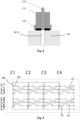
- Figure 9 also shows that the fluidic chip inlets 32 and fluidic chip outlets 33 may be arranged as a matrix of columns and rows (just like the liquid feeding ports and liquid collecting ports, as described above).
- 24 pairs of fluidic chip inlets 32 and fluidic chip outlets 33 are arranged in four columns C1, C2, C3, C4 and six rows L1, L2, L3, L4, L5, L6.
- the drawing also schematically and partially shows a network of valves in the liquid distribution system superimposed with the depiction of the fluidic chip.
- valves in the liquid distribution system may be divided into three groups.
- Each valve in the first group is configured for opening or obstructing fluid communication in the feeding channel between one respective liquid inlet and all of the liquid feeding ports.
- Each valve in the second group is configured for opening or obstructing fluid communication in the feeding channel between all liquid inlets and one respective column of liquid feeding ports.
- Each valve in the third group is configured for opening or closing fluid communication between all liquid inlets and one respective row of liquid feeding ports. By selectively actuating the valves in the third group, it is possible to select a row of liquid feeding ports (and thus a row of fluidic chip inlets in the fluidic chip) which can receive liquid medium.
- valves in all three groups By selectively actuating the valves in all three groups, it is possible to independently feed each fluidic chip inlet with any liquid medium available in the fluid source system.
- FIG. 9 only illustrates the valves of the second group 18b and the valves of the third group 18c.
- one additional row of valves makes it possible to open or close a direct fluidic connection (not through the fluidic chip) between the feeding channel and the collecting channel, via the bypass channels described above.
- a single fluidic chip may be coupled to the liquid distribution system.
- two or more fluidic chips may be coupled to the liquid distribution system.
- a first portion of the liquid feeding ports and liquid collecting ports are fluidically connected to a first fluidic chip
- a second portion of the liquid feeding ports and liquid collecting ports are fluidically connected to a second fluidic chip, etc.
- the two or more fluidic chips are thus multiplexed onto the liquid distribution system.
- the single fluidic chip shown in Figure 9 can be replaced by two or more fluidic chips disposed in parallel.
- the single fluidic chip can be replaced by eight fluidic chips, comprising respectively the chambers, fluidic chip inlets and fluidic chip outlets of: column C1 and rows L1, L2, L3; column C1 and rows L4, L5, L6; column C2 and rows L1, L2, L3; column C2 and rows L4, L5, L6; column C3 and rows L1, L2, L3; column C3 and rows L4, L5, L6; column C4 and rows L1, L2, L3; column C4 and rows L4, L5, L6.
- the liquid distribution system can be constructed and operated in the same manner whether a single fluidic chip or multiple fluidic chips are used and coupled to the liquid distribution system.
- the invention provides a method of feeding liquid to the fluidic chip described above.
- the various liquid inlets of the liquid distribution system are fluidically connected to respective liquid reservoirs, and once the liquid distribution system is connected to the fluidic chip, at least some of the valves of the control module can be actuated (opened or closed) so as to establish a liquid flow path between at least one of the liquid inlets and at least one of the liquid feeding ports, and liquid can be caused to flow from the liquid reservoir to the liquid feeding port via said flow path.
- Liquid then flows within the fluidic chip in at least one chamber, from a fluidic chip inlet to a fluidic chip outlet. Liquid is advantageously collected from the fluidic chip outlet back to the liquid distribution system via at least one of the liquid collecting ports, it flows in a return flow path within the liquid distribution system, then through the liquid outlet thereof and to a liquid collector.
- the liquid reservoirs and the liquid collector may be incorporated in a fluid source system as described above.
- the valves may be actuated by controlling gas pressure at each gas inlet of the pneumatic control module.
- the controlled pressure may for example be selected from two pressure levels, namely a low pressure level and a high pressure level.
- the valve may be closed at the high pressure level and open at the low pressure level.
- FIGS 10A to 10C are diagrams showing various flow paths in a liquid distribution system.
- the liquid inlets are labeled as A to H.
- Each liquid inlet can be fluidically connected to a different liquid reservoir.
- Label I represent the liquid outlet.
- each circle represents a valve.
- Valves 18a of the first group are depicted just below each liquid inlet A-H. Eight such valves are shown in the illustrated example. Valves 18b of the second group (as defined above) are depicted below the valves 18a of the first group. There are four such valves in the illustrated example. Valves 18c of the third group (as defined above) are depicted below the valves 18b of the second group. The valves 18c of the third group are coupled by rows. There are seven such rows in the illustrated example. Within each row, all valves are either open or closed. In all but one row (six first rows from the top in the illustration), the valves correspond to pairs of liquid feeding ports and liquid collecting ports.
- valves per row there are four such pairs of valves per row in the illustration, i.e. one valve per liquid feeding port and one valve per liquid collecting port.
- the remaining row (last row at the bottom in the illustration) comprises one valve per column and make it possible to open or close a bypass flow path, i . e . a flow path which bypasses the fluidic chip ( via a bypass channel as described above).
- Liquid can flow through this liquid flow path, then within a chamber 31 of the fluidic chip, and then again in the liquid distribution system from a liquid collecting port 124 associated with the selected liquid feeding port 123, and then via a liquid flow path 120' leading to the liquid outlet I.
- the configuration shown in Figure 10B corresponds to a step of perfusing one chamber 31 of the fluidic chip with a selected liquid medium.
- valves 18c of the third group may be aligned with the respective liquid feeding ports 123 and liquid collecting ports 124 or may be offset relative to those, within the plane of the respective layer.
- FIG 10C all valves are closed except that one valve 18a of the first group is open (the one below liquid inlet H in the illustration), one valve 18b of the second group is open (the third one from left to right in the illustration) and the valves 18c of one row within the third group are open (this is the seventh row from the top in the illustration).
- a liquid flow path 120" is established in the liquid distribution system 1 from one liquid inlet H directly to the liquid outlet I.
- the liquid flow path 120" bypasses all liquid feeding ports and therefore bypasses the fluidic chip.
- This liquid flow path 120" includes part of the feeding channel, one bypass channel, and part of the collecting channel, as described above.
- the configuration shown in Figure 10C may correspond to a step of washing (at least part of) the feeding channel and the collecting channel. A washing step may be interposed between two different perfusing steps.
- the method of feeding liquid to the fluidic chip may therefore comprise:
- the method may comprise a step of not perfusing liquid to the fluidic chip.
- the method may also comprise a step of washing (at least part of) the feeding channel and collecting channel of the liquid distribution system, bypassing the fluidic chip(s), with a washing solution.
- a washing step may in particular be provided between two successive perfusing steps.
- the method may be automatically implemented, by way of a control unit.
- the control unit may comprise a graphical user interface which allows to choose an input value for one or more parameters.
- the control unit may comprise one or more processors coupled to one or more storage mediums, as well as a computer program comprising instructions stored thereon, for performing various steps described above.
- the control unit may be partly or fully incorporated in the fluid source system and/or may be electronically connected to the fluid source system.
- the control unit may be configured to receive input from any combination of one or more sensors, including for example pressure sensors and/or flow meters, as well as input from the user.
- the one or more pressure sensors and/or flow meters may be within the fluid source system, the liquid distribution system and/or the fluidic chips.
- the control unit may process the input data and/or the user instructions and as a result, provide instructions to actuate the liquid delivery device(s) and the valves described above.
- the control unit may provide the instructions according to any known regulation algorithm in the field of control engineering to correspond a physical parameter (such as a pressure or flow rate) to the user instructions.
- the regulation algorithm involves a closed loop configuration.
- the regulation algorithm may be of the proportional type (P), integral type (I), derivative type (D), proportional-integral type (PI), proportional-derivative type (PD), integral-derivative type (ID), preferably proportional-integral-derivative type (PID) or any other known algorithms in the control theory comprising linear models, deterministic system control, fuzzy logic, and machine-learning.
- the method of feeding liquid to a fluidic chip may be applied for the cultivation of cells or tissues within the fluidic chip, for conducting biological or biochemical assays within the fluidic chip, and for example for screening drugs or other active substances, or for assessing the toxicity of any active substance.
Landscapes
- Chemical & Material Sciences (AREA)
- Health & Medical Sciences (AREA)
- Dispersion Chemistry (AREA)
- Analytical Chemistry (AREA)
- General Health & Medical Sciences (AREA)
- Hematology (AREA)
- Clinical Laboratory Science (AREA)
- Chemical Kinetics & Catalysis (AREA)
- Automatic Analysis And Handling Materials Therefor (AREA)
Abstract
The present invention relates to a liquid distribution system (1) for fluidic chips (3) comprising:
- a liquid distribution layer (12) comprising:
- a plurality of liquid inlets (121);
- a plurality of liquid feeding ports (123);
- a plurality of liquid collecting ports (124);
- at least one liquid outlet (122);
- at least one feeding channel (125a, 125b, 125c) fluidically connecting each liquid inlet (121) to the plurality of liquid feeding ports (123);
- at least one collecting channel (126a, 126b, 126c) fluidically connecting the liquid outlet (122) to the plurality of liquid collecting ports (124);
wherein the liquid distribution layer (12) is configured to be coupled to one or more fluidic chips (3) having a plurality of fluidic chip inlets (32) and fluidic chip outlets (33), each liquid feeding port (123) being configured to be coupled to a fluidic chip inlet (32) and each liquid collecting port (124) being configured to be coupled to a fluidic chip outlet (33);
- a control module (11) comprising a plurality of valves (18), each valve (18) being configured to open or obstruct fluid communication in the feeding channel (125a, 125b, 125c) or in the collecting channel (126a, 126b, 126c) of the liquid distribution layer (12), the control module (11) being configured to selectively establish fluid communication between any of the liquid inlets (121) and any of the liquid feeding ports (123).
- a liquid distribution layer (12) comprising:
- a plurality of liquid inlets (121);
- a plurality of liquid feeding ports (123);
- a plurality of liquid collecting ports (124);
- at least one liquid outlet (122);
- at least one feeding channel (125a, 125b, 125c) fluidically connecting each liquid inlet (121) to the plurality of liquid feeding ports (123);
- at least one collecting channel (126a, 126b, 126c) fluidically connecting the liquid outlet (122) to the plurality of liquid collecting ports (124);
wherein the liquid distribution layer (12) is configured to be coupled to one or more fluidic chips (3) having a plurality of fluidic chip inlets (32) and fluidic chip outlets (33), each liquid feeding port (123) being configured to be coupled to a fluidic chip inlet (32) and each liquid collecting port (124) being configured to be coupled to a fluidic chip outlet (33);
- a control module (11) comprising a plurality of valves (18), each valve (18) being configured to open or obstruct fluid communication in the feeding channel (125a, 125b, 125c) or in the collecting channel (126a, 126b, 126c) of the liquid distribution layer (12), the control module (11) being configured to selectively establish fluid communication between any of the liquid inlets (121) and any of the liquid feeding ports (123).
Description
- The present invention relates to a liquid distribution system for a fluidic chip, an assembly comprising this liquid distribution system and a method of feeding liquid to a fluidic chip using this liquid distribution system.
- An organ-on-a-chip is a microfluidic cell culture device designed to simulate the mechanical environment and study the physiological response of one or more organs. In particular, these devices enable toxicology, drug development or personalized medicine studies to be carried out without animal experimentation.
- It seems essential to have an autonomous system that can deliver microvolumetric quantities of fluids on demand, independently in each culture chip. Yet, automation, ease-of-use and robustness are considered unmet needs that limit the development of the technology.
- Indeed, there is no commercial technology that allows the automatic control of organ-on-chip in parallel simultaneously while being compatible with other lab equipment such as an incubator and a microscope.
- Document
WO 2017/035484 discloses a perfusion manifold assembly for putting a microfluidic device such as an organ-on-a-chip in fluidic communication with a fluid source or another microfluidic device. This technology does not offer the possibility of sequential distribution, does not seem compatible with conventional optical systems, nor with conventional chips made for example of polydimethylsiloxane. - Document
US 2018/0169656 discloses a microfluidic plate comprising a plurality of microfluidic networks and inlets providing access to the microfluidic networks. Each microfluidic network comprises a capillary pressure barrier. Each inlet is formed by an inlet chamber having a bottom surface. This technology does not offer the possibility of sequential distribution, does not seem compatible with conventional chips made for example of polydimethylsiloxane and does not offer a precise control of flowrate. - Document
EP 3705564 discloses a device and method to obtain a controlled medium perfusion and drug injection/removal into standard cell culture dishes (Petri dishes). This technology does not offer the possibility of sequential distribution and does not seem compatible with conventional chips made for example of polydimethylsiloxane. - There is thus a need for a liquid distribution system for a fluidic chip, such as an organ-on-a-chip, which overcomes the limitations of the prior art systems. In particular, there is a need for a liquid distribution system:
- allowing simultaneous distribution and screening of different solutions and molecules, with great robustness and interoperability to maximize ease of use and reproducibility of results;
- allowing the parallel and independent perfusion of several chambers on the chip;
- adapted to existing optical devices.
- The invention relates to the following items.
- Item 1. A liquid distribution system for fluidic chips comprising:
- a liquid distribution layer comprising:
- a plurality of liquid inlets;
- a plurality of liquid feeding ports;
- a plurality of liquid collecting ports;
- at least one liquid outlet;
- at least one feeding channel fluidically connecting each liquid inlet to the plurality of liquid feeding ports;
- at least one collecting channel fluidically connecting the liquid outlet to the plurality of liquid collecting ports;
- a control module comprising a plurality of valves, each valve being configured to open or obstruct fluid communication in the feeding channel or in the collecting channel of the liquid distribution layer, the control module being configured to selectively establish fluid communication between any of the liquid inlets and any of the liquid feeding ports.
-
Item 2. The liquid distribution system of item 1, wherein the liquid feeding ports are arranged in an array of rows and columns; and/or the liquid collecting ports are arranged in an array of rows and columns. -
Item 3. The liquid distribution system ofitem 1 or 2, wherein : - the feeding channel comprises one common portion fluidically connected to the plurality of liquid inlets and fluidically connected to a plurality of branch portions, each branch portion being fluidically connected to a plurality of subbranch portions, each branch portion being optionally configured to feed liquid to a column of liquid feeding ports and each subbranch portion associated with this branch portion being configured to feed liquid to one feeding port within the column; or each branch portion being optionally configured to feed liquid to a row of liquid feeding ports and each subbranch portion associated with this branch portion being configured to feed liquid to one feeding port within the row; and/or
- the collecting channel comprises one common portion fluidically connected to the liquid outlet and fluidically connected to a plurality of branch portions, each branch portion being fluidically connected to a plurality of subbranch portions, each branch portion being optionally configured to collect liquid from a column of liquid collecting ports and each subbranch portion associated with this branch portion being configured to collect liquid from one collecting port within the column; or each branch portion being optionally configured to collect liquid from a row of liquid collecting ports and each subbranch portion associated with this branch portion being configured to collect liquid from one collecting port within the row.
-
Item 4. The liquid distribution system ofitem 3, comprising: - one valve associated with each liquid inlet;
- one valve associated with each respective branch portion of the feeding channel or collecting channel;
- one valve associated with each subbranch portion of the feeding channel or collecting channel.
-
Item 5. The liquid distribution system of any one of items 1 to 4, wherein the valves comprise: - a first group of valves, wherein each valve in this first group is configured for opening or obstructing fluid communication in the feeding channel between one respective liquid inlet and all of the liquid feeding ports;
- a second group of valves, wherein each valve in this second group is configured for opening or obstructing fluid communication in the feeding channel between all liquid inlets and one respective column of liquid feeding ports;
- a third group of valves, wherein each valve in this third group is configured for opening or closing fluid communication between all liquid inlets and one respective row of liquid feeding ports.
-
Item 6. The liquid distribution system of any one of items 1 to 5, wherein the control module is a pneumatic control module, the valves are membrane valves and the pneumatic control module comprises: - a plurality of gas inlets;
- a plurality of gas channels, each gas channel fluidically connecting a gas inlet with a membrane valve.
-
Item 7. The liquid distribution system ofitem 6, comprising a single deformable membrane fixed onto the liquid distribution layer. -
Item 8. The liquid distribution system ofitem -
Item 9. The liquid distribution system of any one ofitems 6 to 8, wherein at least a portion of the gas channels fluidically connects a gas inlet to a single membrane valve. - Item 10. The liquid distribution system of any one of
items 6 to 9, wherein the pneumatic control module comprises at least one layer which comprises gas channels, and one connecting layer which comprises connecting holes interposed between the gas channels and the membrane valves. -
Item 11. The liquid distribution system of any one ofitems 6 to 10, wherein the pneumatic control module comprises at least a first layer comprising a first group of gas channels, and a second layer comprising a second group of gas channels; wherein, preferably, the first group of gas channels is fluidically connected with the second group of membrane valves, and the second group of gas channels is fluidically connected with the first group and third group of membrane valves. -
Item 12. An assembly comprising a fluid source system coupled to the liquid distribution system of any one of items 1 to 11, wherein the fluid source system comprises: - a plurality of liquid reservoirs, wherein each liquid reservoir is fluidically connected with a respective liquid inlet of the liquid distribution layer; and/or
- a liquid collector fluidically connected with the liquid outlet of the liquid distribution layer.
-
Item 13. The assembly ofitem 12, wherein the liquid distribution system is according to any one ofitems 6 to 11 and wherein the fluid source system further comprises: - a gas pressure controller having a plurality of gas lines, wherein each gas line is fluidically connected with a respective gas inlet of the pneumatic control module.
- Item 14. The assembly of
item 13, wherein the gas pressure controller is configured for selectively applying a low pressure level or a high pressure level in each gas line. -
Item 15. The assembly of any one ofitems 12 to 14, comprising at least one liquid delivery device, preferably a liquid delivery device associated with each liquid reservoir. -
Item 16. The assembly of any one ofitems 12 to 15, further comprising the one or more fluidic chips coupled to the liquid distribution system. -
Item 17. The assembly ofitem 16, wherein each liquid feeding port of the liquid distribution system is directly coupled to a fluidic chip inlet, optionally via a gasket, and each liquid collecting port of the liquid distribution system is directly coupled to a fluidic chip outlet, optionally via a gasket. -
Item 18. The assembly ofitem - Item 19. The assembly of any one of
items 16 to 18, wherein the one or more fluidic chips are placed on an optical system, preferably a microscope. - Item 20. A method of feeding liquid to one or more fluidic chips comprising a plurality of fluidic chip inlets and fluidic chip outlets, the method comprising:
- connecting the liquid distribution system of any one of items 1 to 11 to the one or more fluidic chips;
- connecting the liquid inlets of the liquid distribution layer to respective liquid reservoirs;
- actuating at least some of the valves of the control module to establish a liquid flow path between at least one of the liquid inlets and at least one of the liquid feeding ports;
- flowing liquid from a liquid reservoir to at least one of the fluidic chip(s) via said liquid flow path.
-
Item 21. The method of item 20, comprising: - collecting liquid from the at least one of the fluidic chip(s) back to the liquid distribution system via at least one of the liquid collecting ports.
-
Item 22. The method ofitem 20 or 21, wherein the liquid distribution system is according to any one ofitems 6 to 11, and wherein the valves are actuated by controlling pressure at each gas inlet of the pneumatic control module. - Item 23. The method of
item 22, wherein the controlled pressure is selected from two pressure levels, namely a low pressure level and a high pressure level. - Item 24. The method of any one of items 20 to 23, wherein connecting the liquid distribution system to the one or more fluidic chips comprises directly coupling each liquid feeding port of the liquid distribution system to a fluidic chip inlet, optionally via a gasket, and directly coupling each liquid collecting port of the liquid distribution system to a fluidic chip outlet, optionally via a gasket.
- The present invention addresses the need expressed above. In particular, the invention provides a liquid distribution system:
- allowing simultaneous distribution and screening of different solutions and molecules, with great robustness and interoperability to maximize ease of use and reproducibility of results;
- allowing the parallel and independent perfusion of several chambers on the chip;
- adapted to existing optical devices.
- This is made possible owing to a multilayer liquid distribution system comprising in particular a liquid distribution layer and a control module, preferably a pneumatic control module. Liquid may be caused to flow from various liquid reservoirs to the fluidic chip(s) via the liquid distribution layer, according to a variety of possible flow paths which are established by actuating selected valves in the pneumatic control module.
-
-
Figure 1 schematically shows an example of an assembly comprising a liquid distribution system. -
Figure 2 schematically shows an example of a liquid distribution system coupled with a fluidic chip. -
Figure 3 schematically shows an example of a liquid distribution layer within a liquid distribution system. -
Figure 4 schematically shows a cross-sectional view of an example of a liquid distribution system. -
Figure 5 schematically shows an exploded view of part of an example of a liquid distribution system. -
Figure 6 schematically shows an exploded view of another part of an example of a liquid distribution system. -
Figure 7 schematically shows a cross-sectional view of an example of a membrane valve used in a liquid distribution system. -
Figure 8 schematically shows a cross-sectional view of an example of a detail of a liquid connection module coupled to a liquid distribution system. -
Figure 9 schematically shows a cross-sectional view of an example of a fluidic chip. -
Figures 10A to 10C schematically show examples of a fluid path diagram in a liquid distribution system in different states. -
Figures 11 and 12 schematically show cross-sectional views of two other examples of a liquid distribution system. - The invention will now be described in more detail without limitation in the following description.
- Making reference to
Figure 1 , the liquid distribution system 1 can be mechanically coupled to afluid source system 2 via acoupling 7 to form an assembly. Thefluid source system 2 may comprise a plurality ofliquid reservoirs 21 and at least oneliquid collector 22. Theliquid reservoirs 21 are containers which contain liquid media (preferably, different liquid media) adapted to be fed to the liquid distribution system 1, while theliquid collector 22 is a container adapted to collect liquid medium from the liquid distribution system 1. - The liquid distribution system 1 may also be mechanically coupled to one or more
fluidic chips 3 so as to feed liquid (preferably the different liquid media from the liquid reservoirs 21) to the fluidic chip(s) 3 and to collect liquid medium from the fluidic chip(s) 3 and make it flow back to theliquid collector 22 in thefluid source system 2. - As illustrated, the fluidic chip(s) 3 may be placed on an optical system so as to be able to visualize the interior of the fluidic chip(s) 3 during use. As an example, the or each
fluidic chip 3 may be substantially in the shape of a plate having two main substantially planar faces; one main face is in contact with the liquid distribution system 1, whereas the opposite main face may be put in contact with aglass slide 4. Theglass slide 4 may rest on asupport 5, and amicroscope objective 6 may face the glass slide. -
Figure 2 shows in more detail an example of the liquid distribution system 1 coupled with afluidic chip 3 resting on aglass slide 4. As illustrated, the liquid distribution system 1 may comprise aliquid connection module 17, aliquid distribution layer 12, a control module (which may comprise agasket layer 142, amembrane 13, a fluidic connectinglayer 141, a pneumatic connectinglayer 143 and a pneumatic layer 15) and apneumatic input module 16 as will be described in more detail below. Thecoupling 7 ofFigure 1 may comprise theliquid connection module 17 and thepneumatic input module 16. - The liquid distribution system 1, fluidic chip(s) 3 and
glass slide 4 may rest and be partially enclosed in thesupport 5, which may for example be in a conventional 96-well format. Alid 9 may optionally cooperate with thesupport 5 so that, in an open position, theglass slide 4,fluidic chip 3 and liquid distribution system 1 may be placed on thesupport 5 or removed from thesupport 5, and, in a closed position, thefluidic chip 3 and liquid distribution system 1 may be enclosed in an enclosure defined by thesupport 5,glass slide 4 andlid 9. Respective openings may be provided between thesupport 5 and thelid 9 so that theliquid connection module 17 andpneumatic input module 16 can be positioned through the enclosure. - Optionally, a
gas feeding connection 8 may be provided either on thelid 9 or, as shown, on thesupport 5, in order to control the composition of the atmosphere surrounding the fluidic chip(s) 3. - More details will be provided below on the liquid distribution system 1, fluidic chip(s) 3 and
fluid source system 2. - The liquid distribution system 1 may comprise an assembly of layers. Each layer may be substantially in the shape of a plate (notwithstanding any hole, channel, or protrusion, as will be described in more detail below). Thus, each layer may comprise two main faces, each main face being planar, the two main faces being preferably parallel to each other. One main face of each layer in the assembly may be fixed to one main face of another, adjacent layer. Each layer may comprise a number of side faces joining the two main faces together. The side faces may also be planar. The side faces may be perpendicular to the main faces. The total surface area of the side faces may be less than the total surface area of the main faces, preferably less than 10 times the total surface area of the main faces, or less than 100 times the total surface area of the main faces. For at least some of the layers, the perimeter of the main faces may be a rectangle, so that the layer is substantially parallelepiped-shaped. For at least some of the layers, the perimeter of the main faces may be another polygon, such as an octagon (corresponding to a rectangle with a rectangular cutout).
- The liquid distribution system 1 notably comprises a
liquid distribution layer 12, and acontrol module 11. Thecontrol module 11 itself may be made of one or more layers. - The main function of the
liquid distribution layer 12 is to channel liquid to and from the fluidic chip(s) 3. - The main function of the
control module 11 is to selectively open (i.e. establish) or obstruct fluid communication within theliquid distribution layer 12 owing to a plurality of valves, so as to selectively direct liquid from a desired source to a desired chamber of the fluidic chip(s), and to collect liquid from the fluidic chip(s). - Herein, "fluid communication" means an uninterrupted flow path for the fluid. When two elements are said to be "fluidically connected", it means that fluid communication can be established from one element to the other (provided, if necessary, that one or more valves be open).
- Making reference to
Figure 3 , theliquid distribution layer 12 comprises a plurality ofliquid inlets 121. In the illustrated example, there are eightliquid inlets 121, but the number of liquid inlets can vary for example from 2 to 50, preferably from 4 to 20, more preferably from 6 to 12. These liquid inlets are intended to receive liquid from an external source. Preferably, a different liquid medium can be fed to each liquid inlet. - The
liquid distribution layer 12 further comprises a plurality of liquid feedingports 123. In the illustrated example, there are 24 liquid feeding ports, but the number of liquid feeding ports can vary for example from 2 to 400, preferably from 4 to 200, more preferably from 8 to 100, and most preferably from 16 to 32. Theliquid feeding ports 123 are intended to feed liquid to a or thefluidic chip 3. More precisely, each liquid feedingport 123 may be coupled to a respective fluidic chip inlet as will be described in more detail below. - The
liquid feeding ports 123 may be arranged as a matrix ofrows 128 andcolumns 129. In the illustration, there are 6 rows and 4 columns. But the number of columns can vary for example from 1 to 10, preferably from 2 to 8, more preferably from 3 to 6. And the number of rows can vary for example from 1 to 12, preferably from 3 to 10, more preferably from 4 to 8. - The
liquid feeding ports 123 may be geometrically aligned in each row, respectively in each column. Alternatively, liquid feedingports 123 may be staggered in each row and/or in each column. In the illustrated example, theliquid feeding ports 123 are geometrically aligned in eachrow 128, but are not all geometrically aligned (are staggered) in eachcolumn 129. - At least one
feeding channel liquid inlet 121 to theliquid feeding ports 123. It is possible to have a plurality of feeding channels, each feeding channel separately fluidically connecting oneliquid inlet 121 to oneliquid feeding port 123, or to a group of liquid feedingports 123. In this case, each liquid feedingport 123 can be for example fed with liquid from only oneliquid inlet 121. - However, in an alternative variation, as illustrated in the drawing, a single (branched) feeding channel (or manifold) fluidically connects all
liquid inlets 121 to allliquid feeding ports 123. In this case, each liquid feedingport 123 can be fed with liquid from anyliquid inlet 121. - The single feeding channel may in particular comprise a
common portion 125a fluidically connected to the plurality of liquid inlets 121 (namely, to all liquid inlets 121). - The single feeding channel may further comprise a plurality of
branch portions 125b, eachbranch portion 125b being fluidically connected to thecommon portion 125a. Eachbranch portion 125b branches out from thecommon portion 125a. Eachbranch portion 125b may be configured to feed liquid to allliquid feeding ports 123 of the same column. In the illustration, there are fourbranch portions 125b. Thecommon portion 125a may for example branch out into two intermediate segments, each intermediate segment then branching out into twobranch portions 125b, as shown. - The single feeding channel may further comprise a plurality of
subbranch portions 125c. Eachsubbranch portion 125c branches out from abranch portion 125b. Eachsubbranch portion 125c may be configured to feed liquid to only oneliquid feeding port 123. Eachbranch portion 125b may be fluidically connected to a plurality ofsubbranch portions 125c (onesubbranch portion 125c per row of liquid feeding ports). - Instead of directing the liquid from the
common portion 125a to onecolumn 129 of liquid feeding ports via abranch portion 125b, and then to oneliquid feeding port 123 within this column via asubbranch portion 125c (as illustrated), it is possible to do the opposite, i.e. to direct the liquid from thecommon portion 125a to onerow 128 of liquid feeding ports via abranch portion 125b, and then to oneliquid feeding port 123 within this row via asubbranch portion 125c (not shown). - The
liquid distribution layer 12 further comprises a plurality of liquid collectingports 124. In the illustrated example, there are 24 liquid collecting ports, but the number of liquid feeding ports can vary for example from 2 to 400, preferably from 4 to 200, more preferably from 8 to 100, and most preferably from 16 to 32. Theliquid feeding ports 124 are intended to collect liquid from the or afluidic chip 3. More precisely, each liquid collectingport 124 may be coupled to a respective fluidic chip outlet as will be described in more detail below. - Preferably, the number of liquid collecting
ports 124 is the same as the number of liquid feedingports 123, and theliquid feeding ports 123 and liquid collectingports 124 are arranged in pairs. In use, liquid is therefore fed to the or a fluidic chip via at least oneliquid feeding port 123 and simultaneously collected from said fluidic chip via the at least one correspondingliquid collecting port 124 in the pair. However, more complex arrangements are possible, in which two or more liquid feedingports 123 can be paired with oneliquid collecting port 124, or two or more liquid collectingports 124 can be paired with oneliquid feeding port 123. - The
liquid distribution layer 12 further comprises at least oneliquid outlet 122. In the illustrated example, there is a singleliquid outlet 122. The liquid outlet(s) is(are) intended to withdraw liquid from theliquid distribution layer 12. The liquid outlet(s) 122 is(are) fluidically connected to all liquid collectingports 124. - At least one collecting
channel liquid collecting ports 124. It is possible to have a plurality of collecting channels, each collecting channel separately fluidically connecting aliquid outlet 122 to oneliquid collecting port 124, or to a group of liquid collectingports 124. - However, in an alternative variation, as illustrated in the drawing, a single (branched) collecting channel (or manifold) fluidically connects a single
liquid outlet 122 to all liquid collectingports 124. In this case, the liquid collected from all liquid collectingports 124 is directed to the sameliquid outlet 122. - The single collecting channel may in particular comprise a
common portion 126a fluidically connected to theliquid outlet 122. - The single collecting channel may further comprise a plurality of
branch portions 126b, eachbranch portion 126b being fluidically connected to thecommon portion 126a. Eachbranch portion 126b branches out from thecommon portion 126a. Eachbranch portion 126b may be configured to collect liquid from all liquid collectingports 124 of the same column. In the illustration, there are fourbranch portions 126b. Thecommon portion 126a may for example branch out into two intermediate segments, each intermediate segment then branching out into twobranch portions 126b. - The single collecting channel may further comprise a plurality of
subbranch portions 126c. Eachsubbranch portion 126c branches out from abranch portion 126b. Eachsubbranch portion 126c may be configured to collect liquid from only oneliquid collecting port 124. Eachbranch portion 126b may be fluidically connected to a plurality ofsubbranch portions 126c (onesubbranch portion 126c per row of liquid collecting ports). - Instead of directing the liquid from one
liquid collecting port 124 within acolumn 129 via asubbranch portion 126c, and then from saidentire column 129 to thecommon portion 126a via abranch portion 126b (as illustrated), it is possible to do the opposite, i.e. to direct the liquid from oneliquid collecting port 124 within arow 128 via asubbranch portion 126c, and then from saidentire row 128 to thecommon portion 126a via abranch portion 126b (not shown). - One or
more bypass channels 127 fluidically connecting thefeeding channel channel bypass channel 127 may fluidically connect eachbranch portion 125b of the feeding channel to arespective branch portion 126b of the collecting channel. There may thus be onebypass 127 channel per column 129 (or onebypass channel 127 perrow 128 if the alternative arrangement is used). - As can be seen on
Figure 4 , theliquid distribution layer 12 may be overall in the shape of a plate having two main substantially planar faces. A first main face is in contact with thecontrol module 11 and in particular with themembrane 13 of thecontrol module 11. The opposite, second main face is intended to be in contact with the fluidic chip(s) 3. Theliquid distribution layer 12 may have a thickness from 1 mm to 20 mm, preferably from 3 mm to 4 mm. - In the present description, when a layer is substantially in the shape of a plate, as described above, the thickness direction corresponds to the direction which is orthogonal to the main faces of the plate.
- The feeding channel(s) 125 and collecting channel(s) 126 may be provided as grooves on the first main face of the
liquid distribution layer 12. Each groove may have a depth (in the thickness direction) of from 20 µm to 2 mm, preferably from 100 µm to 750 µm. Each groove may have a width (perpendicular to the thickness direction and perpendicular to the longitudinal direction of the channel) of from 20 µm to 2 mm, preferably from 100 µm to 750 µm. - Each
liquid feeding port 123 and liquid collectingport 124 may comprise aprotrusion hole respective feeding channel 125 or collectingchannel 126. - The
liquid distribution layer 12 may be made of any biocompatible hard materials such as polycarbonate, polymethylmethacrylate, polyoxymethylene, cyclic olefin polymers, cyclic olefin copolymers, polytetrafluoroethylene, polyetherimide, and metal alloys. Theliquid distribution layer 12 may be manufactured for example by machining (such as drilling, engraving, carving) a plate of solid material, by injection molding or by additive manufacturing such as 3D-printing. - Making reference to
Figures 4 ,5 and6 , thecontrol module 11 may comprise a plurality ofvalves 18, each valve being configured to open or obstruct fluid communication in thefeeding channel 125 or in the collectingchannel 126 of theliquid distribution layer 12, thecontrol module 11 being configured to selectively establish fluid communication between any of theliquid inlets 121 and any of the liquid feeding ports 123 (and between any of theliquid collecting ports 124 and a or the liquid outlet 122). - The present description is primarily made with reference to a
control module 11 which is a pneumatic control module, i.e. a control module wherein thevalves 18 are actuated by controlling gas pressure. However, it is also possible for thecontrol module 11 to be designed in a different manner. By way of example, piezoelectrically actuated valves can also be employed. - Furthermore, in the
pneumatic control module 11 primarily described herein, thevalves 18 are membrane valves and asingle membrane 13 is used to make all membrane valves. However, it is also possible for themembrane valves 18 to be based on more than one membranes. For example, each membrane valve can have its own dedicated membrane. - The
control module 11 may thus comprise a layer which is amembrane 13 in contact with the first main face of thedistribution layer 12, a connecting layer 14 in contact with the membrane 13 (on the main face of themembrane 13 opposite the main face in contact with the first main face of the distribution layer 12) and apneumatic layer 15 in contact with the connecting layer 14 (on the main face of the connecting layer 14 opposite the main face which is in contact with the membrane 13). - The
membrane 13 may have a thickness from 20 µm to 1 mm, preferably from 50 µm to 500 µm. Themembrane 13 may be made of any biocompatible soft materials such as silicone based materials (e.g., polydimethylsiloxane), fluoroelastomers (such as FKM, FFKM...) or rubbers (such as NBR, EPDM...). - The
pneumatic layer 15 may comprise a plurality ofgas inlets pneumatic layer 15 may comprise a plurality ofgas channels gas channel gas inlet membrane valve 18. In some cases, agas channel gas inlet single membrane valve 18, while in other cases agas channel 1523 may fluidically connect agas inlet 1521 to a plurality ofmembrane valves 18. The connecting layer 14 may comprise a plurality of connectingholes gas channels membrane valves 18. - Each of the
pneumatic layer 15 and connecting layer 14 may itself be a stack of two or more layers. - For example, the
pneumatic layer 15 may comprise afirst layer 151 and asecond layer 152. Each of thefirst layer 151 andsecond layer 152 may be substantially planar. Each of thefirst layer 151 andsecond layer 152 may have a thickness from 1 mm to 20 mm, preferably from 3 mm to 4 mm. Each of thefirst layer 151 andsecond layer 152 may be made of any biocompatible hard materials such as polycarbonate, polymethylmethacrylate, polyoxymethylene, cyclic olefin polymers, cyclic olefin copolymers polytetrafluoroethylene, polyetherimide, and metal alloys. - Each of the
first layer 151 andsecond layer 152 may comprisegas channels gas channels first layer 151 andsecond layer 152. Each groove may have a depth of from 20 µm to 2 mm, preferably from 100 µm to 750µm . Each groove may have a width of from 20 µm to 2 mm, preferably from 100 µm to 750 µm. Preferably, eachgas inlet respective gas channel respective layer - The
pneumatic input module 16 may comprise a firstpneumatic input 16a connected to allgas inlets 1511 of thefirst layer 151 and a secondpneumatic input 16b connected to allgas inlets 1521 of thesecond layer 152. The connection may be substantially leaktight and may be performed for example by clamping . Eachpneumatic input - A main face of the
second layer 152 may be in contact with a main face of the connecting layer 14. A main face of thefirst layer 151 may be in contact with the other main face of thesecond layer 152. Thegas channels 1512 in thefirst layer 151 may be provided on the main face of thefirst layer 151 which is in contact with thesecond layer 152. Thegas channels second layer 152 may be provided on the main face of thesecond layer 152 which is in contact with the connecting layer 14. - The
first layer 151 may comprise a first group ofgas channels 1512. And thesecond layer 152 may comprise a second group ofgas channels 1522 and a third group ofgas channels 1523. These groups of gas channels may have different functions, as will be further explained below. - The
second layer 152 may compriseholes 1524 running through the entire thickness thereof and ensuring fluidic connection between thegas channels 1512 of thefirst layer 151 and therespective membrane valves 18. - Each of the
first layer 151 andsecond layer 152 may be manufactured for example by machining (such as drilling, engraving, carving) a plate of solid material, by injection molding or by additive manufacturing such as 3D-printing. - It should be noted that, instead of being made of a stack of two distinct layers, the
pneumatic layer 15 can be made of a single-piece layer, in which case all gas channels may be located on the main face of thepneumatic layer 15 in contact with the connecting layer 14. Conversely, thepneumatic layer 15 can comprise a stack of more than two layers, such as three layers, each such layer comprising gas channels, formed on a main face of the layer facing another layer of the pneumatic layer or facing the connecting layer 14, and corresponding gas inlets. - The connecting layer 14 comprises connecting
holes gas channels pneumatic layer 15 andrespective membrane valves 18. On the main face of the connecting layer 14 in contact with thepneumatic layer 15, each connectinghole 1431 is joined with agas channel hole 1524 of thepneumatic layer 15 which is itself joined with agas channel 1512. - Contrary to what is illustrated, it is possible for the connecting layer 14 to be made of a single piece.
- Alternatively, and as shown in the drawings, the connecting layer 14 may itself be a stack of a plurality of elements, such as: a pneumatic connecting
layer 143, in contact with thepneumatic layer 15; a fluidic connectinglayer 141, in contact with theliquid distribution layer 12; and optionally agasket layer 142 interposed between the pneumatic connectinglayer 143 and fluidic connectinglayer 141. - In this case, each connecting hole comprises a
portion 1431 which is a hole running through the entire thickness of the pneumatic connectinglayer 143, optionally aportion 1421 which is a hole running through the entire thickness of thegasket layer 142 if present, and aportion 1411 which is a hole running through the entire thickness of the fluidic connectinglayer 141. For each connecting hole, these portions are aligned. - In this case, the pneumatic connecting
layer 143 may comprise additional throughholes 1432 which are not connecting holes. On the main face of the pneumatic connectinglayer 143 in contact with thepneumatic layer 15, each additional throughhole 1432 is joined with agas channel hole 1524 of thepneumatic layer 15 which is itself joined with agas channel 1512. On the opposite main face of the pneumatic connectinglayer 143, which either contacts the fluidic connectinglayer 141 or thegasket layer 142 if present, the throughhole 1432 is closed (by the fluidic connectinglayer 141 orgasket layer 142 respectively). - Therefore, the
pneumatic layer 15 together with the pneumatic connectinglayer 143 may be provided as a first set, while the fluidic connectinglayer 141, themembrane 13 and theliquid distribution layer 12 may be provided as a second set. Theoptional gasket layer 142 can be in the first set or in the second set. The first set may comprise a number of gas connections available for fluid connection to membrane valves, and may be adapted to be coupled to different types of second set, wherein only a subset of these gas connections are actually fluidically connected to membrane valves for each type of second set. This make it possible to employ the same first set with different types of fluidic chips, whereas only the second set needs to be selected to conform to the configuration of particular fluidic chips. When a change is made and the second set becomes associated with another first set (and thus with another type of fluidic chip), some or all of the additional throughholes 1432 may becomeportions 1431 of connecting holes, and some of all of theportions 1431 of connecting holes may become additional throughholes 1432. - The first set may be reusable while the second set may be disposable after use, as only the second set comes into contact with the liquid and may thus get possibly contaminated by substances contained in the liquid.
- Alternatively, the second set may comprise only the fluidic connecting layer 141 (and optionally the gasket layer 142), while the
liquid distribution layer 12 andmembrane 13 may be provided as a third set. In this case, the first set may be reusable and permanent, the third set may be disposable after use, and the second set may be reusable and may be employed as a (changeable) adapter between the permanent first set and the disposable third set. - Each of the
gasket layer 142, fluidic connectinglayer 141 and pneumatic connectinglayer 143 may be substantially planar. Each of the fluidic connectinglayer 141 and pneumatic connectinglayer 143 may have a thickness from 1 mm to 2 mm, preferably from 3 mm to 4 mm. Each of the fluidic connectinglayer 141 and pneumatic connectinglayer 143 may be made of any biocompatible hard materials such as polycarbonate, polymethylmethacrylate, polyoxymethylene, cyclic olefin polymers, cyclic olefin copolymers polytetrafluoroethylene, polyetherimide, and metal alloys. Thegasket layer 142 may have a thickness from 20 µm to 2 mm, preferably from 100 µm to 1 mm. Thegasket layer 142 may be made of elastomers such as silicone elastomers, polyurethane, any type of rubber (e.g., EPDM). - Each of the fluidic connecting
layer 141 and pneumatic connectinglayer 143 may be manufactured for example by machining (such as drilling, engraving, carving) a plate of solid material, by injection molding or by additive manufacturing such as 3D-printing. Thegasket layer 142 may be manufactured for example by injection molding, mechanic or laser cutting, 3D printing. - The connecting
holes - As already mentioned above, the
pneumatic control module 11 comprises a number ofmembrane valves 18. - An example of a
membrane valve 18 is shown in more detail inFigure 7 . Themembrane valve 18 is formed by an area of themembrane 13 which cooperates with aprotrusion 1350 in a channel 130 (which can be a feeding channel or a collecting channel). Theprotrusion 1350 is substantially aligned with a connectinghole 1411. In the closed position, themembrane 13 bears, i.e. is pressed against theprotrusion 1350 so as to obstruct the passage of liquid (i.e. to obstruct fluid communication). In the open position, themembrane 13 is positioned at a distance from theprotrusion 1350, thereby enabling the passage of liquid (and establishing fluid communication) along thechannel 125 around theprotrusion 1350. - Whether the
membrane valve 18 is in the open or closed position depends on the gas pressure within the connectinghole 1411, which is (approximately) equal to the pressure within thegas channel hole 1411. If the pressure in thegas channel hole 1411 is sufficiently high, themembrane 13 is pressed against theprotrusion 1350. If the pressure in thegas channel hole 1411 is sufficiently low, themembrane 13 locally deforms and is displaced away from theprotrusion 1350. - As illustrated on the drawing, the connecting
hole 1411 may comprise anenlarged end 1412 on the main face of the connecting layer 14 in contact with themembrane 13, so as to facilitate the local deformation of themembrane 13 away from theprotrusion 1350. - The
enlarged end 1412 may have an internal maximum dimension perpendicular to the thickness direction (e.g. a diameter) from 50 µm to 2 mm, preferably from 500 µm to 1.5 mm. Theprotrusion 1350 may run on the entire width of thechannel 125 and may be level with the main face of theliquid distribution layer 12 facing themembrane 13, excluding the channels. - Making reference to
Figure 5 andFigure 8 , theliquid connection module 17 comprises a plurality oftubes 173, wherein eachtube 173 is fluidically connected with aliquid inlet 121 orliquid outlet 122 of theliquid distribution layer 12. Aconnector 171 may be arranged around eachrespective tube 173 and aseal 172 may be arranged within an inner portion of theconnector 172. - The
membrane 13 may comprise throughholes 131 aligned with theliquid inlets 121 andliquid outlets 122. These throughholes 131 may be manufactured by drilling or directly by injection molding. The fluidic connectinglayer 141, if present, may also comprise throughholes 1412 aligned with the throughholes 131 of themembrane 13 and with theliquid inlets 121 andliquid outlets 122. - Each
connector 171 may therefore be pressed against a throughhole 1412 of the fluidic connectinglayer 141, thus ensuring the required fluidic connection with the correspondingliquid inlet 121 orliquid outlet 122. - All
connectors 171 may be included in a frame placed in contact with the fluidic connectinglayer 171. - A cut-out may be provided in the pneumatic connecting
layer 143 and in thepneumatic layer 15 so as to leave the throughholes 1412 of the fluidic connectinglayer 141 accessible for the connectors 1710. - Thus, the
liquid distribution layer 12, themembrane 13 and the fluidic connectinglayer 141 may have the same external dimensions (perpendicularly to the thickness direction) so that they are essentially flush when assembled. Similarly, the pneumatic connectinglayer 143 and thepneumatic layer 15 may have the same external dimensions (perpendicularly to the thickness direction) so that they are essentially flush when assembled. When all layers are assembled, part of the main face of the fluidic connectinglayer 141 facing thecontrol module 11 is not covered by thecontrol module 11 so that it can accommodate theconnectors 171 of theliquid connection module 17. - The various layers described above, including the membrane, may be assembled and sealed together by any known means, such as mechanical clamping and/or applying an adhesive such as a pressure sensitive adhesive (PSA) between two adjacent layers.
- Making reference to
figure 11 (which is a variant offigure 4 , wherein the same reference numerals have the same meaning), another, simplified version of acontrol module 11 can be implemented. This version, which is also a pneumatic control module, can be connected to aliquid distribution layer 12 which is as described above. Thecontrol module 11 can comprise amembrane 13 as described above, apneumatic layer 15, but no connecting layer 14. - The
pneumatic layer 15 may comprise a plurality ofgas channels 153. At one end of eachgas channel 153 is amembrane valve 18 as described elsewhere. At the other end of eachgas channel 153 is agas inlet 154. Eachgas channel 153 therefore fluidically connects amembrane valve 18 to agas inlet 154. Eachgas inlet 154 can be configured for receiving one end of a respective gas channel or tube of thepneumatic input module 16. In particular, eachgas inlet 154 may be a connection port, comprising for example an enlarged portion within thegas channel 153 and/or a protrusion away from the face of thepneumatic layer 15 where thegas inlet 154 is located. - The
gas inlets 154 can be arranged on one main face of thepneumatic layer 15, which is also one main face of the control module 11 (contrary to what was described above in relation toFigure 4 , where the gas inlets are arranged on a side face of a layer of the control module 11). - In some embodiments, each
gas channel 153 fluidically connects asingle membrane valve 18 to asingle gas inlet 154. In other embodiments, for at least some of thegas channels 153, thegas channel 153 fluidically connects two ormore membrane valves 18 to asingle gas inlet 154. - As illustrated, the
pneumatic layer 15 may itself be a stack of two or more layers, such as afirst layer 15a and asecond layer 15b. Thefirst layer 15a may be in contact with themembrane 13 and may accommodate the (preferably enlarged) ends of thegas channels 153 which cooperate with themembrane 13 to form themembrane valves 18. The portions of thegas channels 153 running within thefirst layer 15a may be oriented substantially perpendicular to the main faces of thefirst layer 15a. Thesecond layer 15b may be fixed to the main face of thefirst layer 15a which is opposite themembrane 13. Thesecond layer 15b may comprise thegas inlets 154. Each portion of agas channel 153 running within thesecond layer 15b may comprise a first part oriented substantially parallel to the main faces of thesecond layer 15b, as well as a second part oriented substantially perpendicular to these main faces (including in particular the gas inlets 154). - This makes it possible to facilitate the connection of the
pneumatic input module 16 to the pneumatic layer 15: for example allgas inlets 154 may be aligned or arranged as an array in one area of a main face of the pneumatic layer 15 (which is also a main face of the control module 11) facilitating a simultaneous connection of all channels or tubes of thepneumatic input module 16 to all of thesegas inlets 154, for example using a standard connector, regardless of the pattern of themembrane valves 18. - The
pneumatic layer 15 may be made of any biocompatible hard materials such as polycarbonate, polymethylmethacrylate, polyoxymethylene, cyclic olefin polymers, cyclic olefin copolymers polytetrafluoroethylene, polyetherimide, and metal alloys. It may have a thickness of from 1 to 20 mm, preferably from 3 to 4 mm. It can be assembled for example by mechanical clamping and/or applying an adhesive such as a pressure sensitive adhesive. - In yet another variant, the
pneumatic layer 15 may be of unitary construction. In this case, and as shown infigure 12 , the entirety of thegas channels 153 may be oriented substantially perpendicular to the main faces of thepneumatic layer 15. This other variant is of even simpler design than the previous one. In this case, each channel or tube of thepneumatic input module 16 can be connected to arespective gas channel 153 at a position aligned with the correspondingmembrane valve 18. - As shown in
Figure 1 , thefluid source system 2 comprises a plurality ofliquid reservoirs 21 and at least oneliquid collector 22. Eachliquid reservoir 21 is fluidically connected to oneliquid inlet 121 of the liquid distribution system 1, via arespective tube 173 of theliquid connection module 17. Therefore, several different liquid media can be fed to the fluidic chip(s) 3 from the respectiveliquid reservoirs 21, via arespective tube 173 of theliquid connection module 17, then via aliquid inlet 121 of theliquid distribution system 12, then via afeeding channel 125 of theliquid distribution system 12, and via aliquid feeding port 123 of the liquid distribution system 1. - Liquid medium can be collected from the fluidic chip(s) 3, via a
liquid collecting port 124 of the liquid distribution system 1, then via a collectingchannel 126 of the liquid distribution system 1, via aliquid outlet 122 of the liquid distribution system 1, via arespective tube 173 of theliquid connection module 17, and to a or theliquid collector 22 in thefluid source system 2. - Liquid movement may be effected using a liquid delivery device. Preferably, at least one liquid delivery device is associated with each liquid reservoir. The liquid delivery device can be integrated in the
fluid source system 2 itself. The liquid delivery devices can be in particular peristaltic pumps, piston pumps, syringe pumps, diaphragm pumps or pressure-controlled delivery devices. Pressure-controlled delivery devices are preferred; they rely on pressurizing the liquid reservoirs themselves. - The
fluid source system 2 advantageously also comprises a pneumatic source device - although said pneumatic source device can also be provided as a distinct element separate from thefluid source system 2. The pneumatic source system comprises a pressure controller. When a pressure controller is present, optionally, it can also actuate the pressure-controlled delivery devices used for effecting liquid movement. Alternatively, a dedicated pressure controller may be used in the pneumatic source system, and one or more other dedicated pressure controller(s) may actuate the pressure-controlled delivery devices used for effecting liquid movement. - The pressure controller can independently control gas pressure within each gas channel or tube of the pneumatic input(s) 16a, 16b shown on
Figure 6 . Therefore, the pressure control can independently control gas pressure within eachgas channel pneumatic layer 15. - It may be sufficient for the gas pressure within each
gas channel - The gas the pressure of which is controlled owing to the pressure controller can be for example air (such as medical air), hydrogen, carbon dioxide, or a noble gas such as helium or argon.
- The pressure controller can be an electromechanical device comprising one or more valves, such as proportional valves, and one or more pressure sensors, and a gas source (or a line leading to a gas source) such as a pressurized gas bottle. The opening (or closing) of the valve(s) can be controlled based on input from the pressure sensor(s) and based on the pressure setpoint(s) set by the user or by the control unit described further below.
- By "fluidic chip" is meant a chip comprising at least one channel wherein liquid medium can flow. The fluidic chip can be millifluidic, microfluidic or nanofluidic. Preferably, it is a microfluidic chip.
- By "millifluidic" is meant a system in which the minimal channel dimensions are of the order of 1-10 mm. By "microfluidic" is meant a system in which the minimal channel dimensions are of the order of 1 to less than 1000 µm. By "nanofluidic" is meant a system in which the minimal channel dimensions are of the order of less than 1 µm.
- The fluidic chips may be in particular organ-on-chips or tissue-on-chips. By "organ-on-a-chip" or "tissue-on-a-chip" is meant a multi-channel 2-D or 3-D microfluidic cell culture chip that simulates the activities, mechanics and physiological response of entire organs, organ systems or tissues. The organ-on-a-chip can in particular be a brain-on-a-chip or a guts-on-a-chip.
- The fluidic chips may be made of a polymer material, such as a silicone based material (e.g., polydimethylsiloxane). Other possible materials include other biocompatible hard materials such as polycarbonate, polymethylmethacrylate, polyoxymethylene, cyclic olefin polymers, cyclic olefin copolymers, polytetrafluoroethylene, polyetherimide, and metal alloys.
- Making reference to
Figure 9 , the fluidic chip may comprise at least one, and preferably a plurality of chambers 31 (or channels), eachchamber 31 comprising at least onefluidic chip inlet 32 and at least onefluidic chip outlet 33. In some cases, eachchamber 31 may have a singlefluidic chip inlet 32 and a singlefluidic chip outlet 33. - The fluidic chip may substantially in the shape of a plate. The
chambers 31 may run mostly parallel to the plane of the plate, in the interior of the fluidic chip. Thefluidic chip inlets 32 andfluidic chip inlets 33 may run mostly perpendicular to the plane so as to make eachchamber 31 accessible from one main face of the fluidic chip. - When the liquid distribution system is coupled to the fluidic chip, the
liquid feeding ports 123 and liquid collectingports 124 are connected respectively to thefluidic chip inlets 32 andfluidic chip outlets 33 of the fluidic chip. For example, making again reference toFigure 4 , if theliquid feeding ports 123 and liquid collectingports 124 compriserespective protrusions liquid distribution layer 12, theseprotrusions fluidic chip inlets 32 andfluidic chip outlets 33 to ensure the connection. Gaskets (not shown) may be added, if needed, to make the assembly leaktight. Alternatively, protrusions can rather be provided on thefluidic chip inlets 32 andfluidic chip outlets 33 for direct insertion into theliquid feeding ports 123 and liquid collectingports 124 respectively. By "direct" insertion or coupling is meant that there is no intermediate tubing or other liquid conducting element. -
Figure 9 also shows that thefluidic chip inlets 32 andfluidic chip outlets 33 may be arranged as a matrix of columns and rows (just like the liquid feeding ports and liquid collecting ports, as described above). - In the illustrated example, 24 pairs of
fluidic chip inlets 32 andfluidic chip outlets 33 are arranged in four columns C1, C2, C3, C4 and six rows L1, L2, L3, L4, L5, L6. - The drawing also schematically and partially shows a network of valves in the liquid distribution system superimposed with the depiction of the fluidic chip.
- The valves in the liquid distribution system may be divided into three groups.
- Each valve in the first group is configured for opening or obstructing fluid communication in the feeding channel between one respective liquid inlet and all of the liquid feeding ports. By selectively actuating the valves in the first group, it is possible to select which liquid medium flows into the liquid distribution system (and thus into the fluidic chip).
- Each valve in the second group is configured for opening or obstructing fluid communication in the feeding channel between all liquid inlets and one respective column of liquid feeding ports. By selectively actuating the valves in the second group, it is possible to select a column of liquid feeding ports (and thus a column of fluidic chip inlets in the fluidic chip) which can receive liquid medium.
- Each valve in the third group is configured for opening or closing fluid communication between all liquid inlets and one respective row of liquid feeding ports. By selectively actuating the valves in the third group, it is possible to select a row of liquid feeding ports (and thus a row of fluidic chip inlets in the fluidic chip) which can receive liquid medium.
- By selectively actuating the valves in all three groups, it is possible to independently feed each fluidic chip inlet with any liquid medium available in the fluid source system.
-
Figure 9 only illustrates the valves of thesecond group 18b and the valves of thethird group 18c. - In the third group, one additional row of valves (row L7 on the drawings) makes it possible to open or close a direct fluidic connection (not through the fluidic chip) between the feeding channel and the collecting channel, via the bypass channels described above.
- A single fluidic chip may be coupled to the liquid distribution system.
- Alternatively, two or more fluidic chips may be coupled to the liquid distribution system. In this case, a first portion of the liquid feeding ports and liquid collecting ports are fluidically connected to a first fluidic chip, a second portion of the liquid feeding ports and liquid collecting ports are fluidically connected to a second fluidic chip, etc. The two or more fluidic chips are thus multiplexed onto the liquid distribution system.
- For example, the single fluidic chip shown in
Figure 9 can be replaced by two or more fluidic chips disposed in parallel. For example, the single fluidic chip can be replaced by eight fluidic chips, comprising respectively the chambers, fluidic chip inlets and fluidic chip outlets of: column C1 and rows L1, L2, L3; column C1 and rows L4, L5, L6; column C2 and rows L1, L2, L3; column C2 and rows L4, L5, L6; column C3 and rows L1, L2, L3; column C3 and rows L4, L5, L6; column C4 and rows L1, L2, L3; column C4 and rows L4, L5, L6. - The liquid distribution system can be constructed and operated in the same manner whether a single fluidic chip or multiple fluidic chips are used and coupled to the liquid distribution system.
- The invention provides a method of feeding liquid to the fluidic chip described above. Once the various liquid inlets of the liquid distribution system are fluidically connected to respective liquid reservoirs, and once the liquid distribution system is connected to the fluidic chip, at least some of the valves of the control module can be actuated (opened or closed) so as to establish a liquid flow path between at least one of the liquid inlets and at least one of the liquid feeding ports, and liquid can be caused to flow from the liquid reservoir to the liquid feeding port via said flow path. Liquid then flows within the fluidic chip in at least one chamber, from a fluidic chip inlet to a fluidic chip outlet. Liquid is advantageously collected from the fluidic chip outlet back to the liquid distribution system via at least one of the liquid collecting ports, it flows in a return flow path within the liquid distribution system, then through the liquid outlet thereof and to a liquid collector.
- The liquid reservoirs and the liquid collector may be incorporated in a fluid source system as described above.
- When the control module is a pneumatic control module, the valves may be actuated by controlling gas pressure at each gas inlet of the pneumatic control module. As described above, the controlled pressure may for example be selected from two pressure levels, namely a low pressure level and a high pressure level. The valve may be closed at the high pressure level and open at the low pressure level.
-
Figures 10A to 10C are diagrams showing various flow paths in a liquid distribution system. In each of these diagrams, the liquid inlets are labeled as A to H. Each liquid inlet can be fluidically connected to a different liquid reservoir. Label I represent the liquid outlet. Below the line of liquid inlets and outlet, each circle represents a valve. -
Valves 18a of the first group (as defined above) are depicted just below each liquid inlet A-H. Eight such valves are shown in the illustrated example.Valves 18b of the second group (as defined above) are depicted below thevalves 18a of the first group. There are four such valves in the illustrated example.Valves 18c of the third group (as defined above) are depicted below thevalves 18b of the second group. Thevalves 18c of the third group are coupled by rows. There are seven such rows in the illustrated example. Within each row, all valves are either open or closed. In all but one row (six first rows from the top in the illustration), the valves correspond to pairs of liquid feeding ports and liquid collecting ports. There are four such pairs of valves per row in the illustration, i.e. one valve per liquid feeding port and one valve per liquid collecting port. The remaining row (last row at the bottom in the illustration) comprises one valve per column and make it possible to open or close a bypass flow path, i.e. a flow path which bypasses the fluidic chip (via a bypass channel as described above). - In
Figure 10A , all valves are closed and there is no liquid flow in the liquid distribution system or in the fluidic chip. - In
Figure 10B , all valves are closed except that onevalve 18a of the first group is open (the one below liquid inlet C in the illustration), onevalve 18b of the second group is open (the third one from left to right in the illustration) and thevalves 18c of one row within the third group are open (this is the fifth row from the top in the illustration). As a result, aliquid flow path 120 is established from one liquid inlet C to a single selectedliquid feeding port 123. Theopen valve 18b of the second group orients the flow path to one column of liquid feeding ports, and theopen valves 18c of the third group orient the flow path to one row of liquid feeding ports. The selectedliquid feeding port 123 is the one present in this column and row. Liquid can flow through this liquid flow path, then within achamber 31 of the fluidic chip, and then again in the liquid distribution system from aliquid collecting port 124 associated with the selectedliquid feeding port 123, and then via a liquid flow path 120' leading to the liquid outlet I. The configuration shown inFigure 10B corresponds to a step of perfusing onechamber 31 of the fluidic chip with a selected liquid medium. - It should be mentioned that the
valves 18c of the third group may be aligned with the respectiveliquid feeding ports 123 and liquid collectingports 124 or may be offset relative to those, within the plane of the respective layer. - In
Figure 10C , all valves are closed except that onevalve 18a of the first group is open (the one below liquid inlet H in the illustration), onevalve 18b of the second group is open (the third one from left to right in the illustration) and thevalves 18c of one row within the third group are open (this is the seventh row from the top in the illustration). As a result, aliquid flow path 120" is established in the liquid distribution system 1 from one liquid inlet H directly to the liquid outlet I. Theliquid flow path 120" bypasses all liquid feeding ports and therefore bypasses the fluidic chip. Thisliquid flow path 120" includes part of the feeding channel, one bypass channel, and part of the collecting channel, as described above. The configuration shown inFigure 10C may correspond to a step of washing (at least part of) the feeding channel and the collecting channel. A washing step may be interposed between two different perfusing steps. - The method of feeding liquid to the fluidic chip may therefore comprise:
- perfusing liquid from a first liquid reservoir to a chamber of a fluidic chip, followed by perfusing liquid from a second liquid reservoir (different from the first liquid reservoir) to the same chamber; and/or
- perfusing liquid from a liquid reservoir to a first chamber of a fluidic chip, followed by perfusing liquid from the same or a different liquid reservoir to a (different) second chamber of the same or another fluidic chip; and/or
- simultaneously perfusing liquid from a liquid reservoir to two or more chambers within one or more fluidic chips.
- Between two successive perfusing steps, the method may comprise a step of not perfusing liquid to the fluidic chip.
- The method may also comprise a step of washing (at least part of) the feeding channel and collecting channel of the liquid distribution system, bypassing the fluidic chip(s), with a washing solution. Such a washing step may in particular be provided between two successive perfusing steps.
- The method may be automatically implemented, by way of a control unit.
- The control unit may comprise a graphical user interface which allows to choose an input value for one or more parameters.
- The control unit may comprise one or more processors coupled to one or more storage mediums, as well as a computer program comprising instructions stored thereon, for performing various steps described above. The control unit may be partly or fully incorporated in the fluid source system and/or may be electronically connected to the fluid source system.
- The control unit may be configured to receive input from any combination of one or more sensors, including for example pressure sensors and/or flow meters, as well as input from the user. The one or more pressure sensors and/or flow meters may be within the fluid source system, the liquid distribution system and/or the fluidic chips.
- The control unit may process the input data and/or the user instructions and as a result, provide instructions to actuate the liquid delivery device(s) and the valves described above.
- The control unit may provide the instructions according to any known regulation algorithm in the field of control engineering to correspond a physical parameter (such as a pressure or flow rate) to the user instructions. In some preferred embodiments, the regulation algorithm involves a closed loop configuration. The regulation algorithm may be of the proportional type (P), integral type (I), derivative type (D), proportional-integral type (PI), proportional-derivative type (PD), integral-derivative type (ID), preferably proportional-integral-derivative type (PID) or any other known algorithms in the control theory comprising linear models, deterministic system control, fuzzy logic, and machine-learning.
- The method of feeding liquid to a fluidic chip may be applied for the cultivation of cells or tissues within the fluidic chip, for conducting biological or biochemical assays within the fluidic chip, and for example for screening drugs or other active substances, or for assessing the toxicity of any active substance.
Claims (15)
- A liquid distribution system (1) for fluidic chips (3) comprising:- a liquid distribution layer (12) comprising:- a plurality of liquid inlets (121);- a plurality of liquid feeding ports (123);- a plurality of liquid collecting ports (124);- at least one liquid outlet (122);- at least one feeding channel (125a, 125b, 125c) fluidically connecting each liquid inlet (121) to the plurality of liquid feeding ports (123);- at least one collecting channel (126a, 126b, 126c) fluidically connecting the liquid outlet (122) to the plurality of liquid collecting ports (124);
wherein the liquid distribution layer (12) is configured to be coupled to one or more fluidic chips (3) having a plurality of fluidic chip inlets (32) and fluidic chip outlets (33), each liquid feeding port (123) being configured to be coupled to a fluidic chip inlet (32) and each liquid collecting port (124) being configured to be coupled to a fluidic chip outlet (33);- a control module (11) comprising a plurality of valves (18), each valve (18) being configured to open or obstruct fluid communication in the feeding channel (125a, 125b, 125c) or in the collecting channel (126a, 126b, 126c) of the liquid distribution layer (12), the control module (11) being configured to selectively establish fluid communication between any of the liquid inlets (121) and any of the liquid feeding ports (123). - The liquid distribution system (1) of claim 1, wherein the liquid feeding ports (123) are arranged in an array of rows (128) and columns (129); and/or the liquid collecting ports are arranged in an array of rows (128) and columns (129).
- The liquid distribution system of claim 1 or 2, wherein :- the feeding channel (125a, 125b, 125c) comprises one common portion (125a) fluidically connected to the plurality of liquid inlets (121) and fluidically connected to a plurality of branch portions (125b), each branch portion (125b) being fluidically connected to a plurality of subbranch portions (125c), each branch portion (125b) being optionally configured to feed liquid to a column (129) of liquid feeding ports (123) and each subbranch portion (125c) associated with this branch portion (125b) being configured to feed liquid to one feeding port (123) within the column (129); or each branch portion (125b) being optionally configured to feed liquid to a row (128) of liquid feeding ports (123) and each subbranch portion (125c) associated with this branch portion (125b) being configured to feed liquid to one feeding port (123) within the row (128); and/or- the collecting channel (126a, 126b, 126c) comprises one common portion (126a) fluidically connected to the liquid outlet (122) and fluidically connected to a plurality of branch portions (126b), each branch portion (126b) being fluidically connected to a plurality of subbranch portions (126c), each branch portion (126b) being optionally configured to collect liquid from a column (129) of liquid collecting ports (124) and each subbranch portion (126c) associated with this branch portion (126b) being configured to collect liquid from one collecting port (124) within the column (129); or each branch portion (126b) being optionally configured to collect liquid from a row (128) of liquid collecting ports (124) and each subbranch portion (126c) associated with this branch portion (126b) being configured to collect liquid from one collecting port (124) within the row (128).
- The liquid distribution system (1) of claim 3, comprising:- one valve (18a) associated with each liquid inlet (121);- one valve (18b) associated with each respective branch portion (125b, 126b) of the feeding channel or collecting channel;- one valve (18c) associated with each subbranch portion (125c, 126c) of the feeding channel or collecting channel.
- The liquid distribution system (1) of any one of claims 1 to 4, wherein the valves (18) comprise:- a first group of valves (18a), wherein each valve (18a) in this first group is configured for opening or obstructing fluid communication in the feeding channel (125a) between one respective liquid inlet (121) and all of the liquid feeding ports (123);- a second group of valves (18b), wherein each valve (18b) in this second group is configured for opening or obstructing fluid communication in the feeding channel (125b) between all liquid inlets (121) and one respective column (129) of liquid feeding ports (123);- a third group of valves (18c), wherein each valve (18c) in this third group is configured for opening or closing fluid communication between all liquid inlets (121) and one respective row (128) of liquid feeding ports (123).
- The liquid distribution system (1) of any one of claims 1 to 5, wherein the control module (11) is a pneumatic control module, the valves (18) are membrane valves and the pneumatic control module (11) comprises:- a plurality of gas inlets (1511, 1521, 154);- a plurality of gas channels (1512, 1522, 1523, 153), each gas channel (1512, 1522, 1523, 154) fluidically connecting a gas inlet (1511, 1521, 154) with a membrane valve (18).
- The liquid distribution system (1) of claim 6, comprising a single deformable membrane (13) fixed onto the liquid distribution layer (12).
- The liquid distribution system (1) of claim 6 or 7, wherein the feeding channel (125a, 125b, 125c) and/or collecting channel (126a, 126b, 126c) in the liquid distribution layer (12) comprise a plurality of protrusions (1350) against which respective membrane valves (18) press to obstruct fluid communication in said feeding channel (125a, 125b, 125c) and/or collecting channel (126a, 126b, 126c).
- The liquid distribution system (1) of any one of claims 6 to 8, wherein at least a portion of the gas channels (1512, 1522, 153) fluidically connects a gas inlet (1511, 1521, 154) to a single membrane valve (18).
- The liquid distribution system (1) of any one of claims 6 to 9, wherein the pneumatic control module (11) comprises at least one layer (151, 152) which comprises gas channels (1512, 1522, 1523), and one connecting layer (14) which comprises connecting holes (1431, 1411) interposed between the gas channels (1512, 1522, 1523) and the membrane valves (18).
- The liquid distribution system (1) of any one of claims 6 to 10, wherein the pneumatic control module (11) comprises at least a first layer (151) comprising a first group of gas channels (1512), and a second layer (152) comprising a second group of gas channels (1522, 1523); wherein, preferably, the first group of gas channels (1512) is fluidically connected with the second group of membrane valves (18b), and the second group of gas channels (1522, 1523) is fluidically connected with the first group and third group of membrane valves (18a, 18c).
- An assembly comprising a fluid source system (2) coupled to the liquid distribution system (1) of any one of claims 1 to 11, wherein the fluid source system (1) comprises:- a plurality of liquid reservoirs (21), wherein each liquid reservoir (21) is fluidically connected with a respective liquid inlet (121) of the liquid distribution layer (12); and/or- a liquid collector (22) fluidically connected with the liquid outlet (122) of the liquid distribution layer (12).
- The assembly of claim 12, wherein the liquid distribution system (1) is according to any one of claims 6 to 11 and wherein the fluid source system (2) further comprises:- a gas pressure controller having a plurality of gas lines, wherein each gas line is fluidically connected with a respective gas inlet (1511, 1512) of the pneumatic control module (11), wherein the gas pressure controller is preferably configured for selectively applying a low pressure level or a high pressure level in each gas line.
- A method of feeding liquid to one or more fluidic chips (3) comprising a plurality of fluidic chip inlets (32) and fluidic chip outlets (33), the method comprising:- connecting the liquid distribution system (1) of any one of claims 1 to 11 to the one or more fluidic chips;- connecting the liquid inlets (121) of the liquid distribution layer (12) to respective liquid reservoirs (21);- actuating at least some of the valves (18) of the control module (11) to establish a liquid flow path between at least one of the liquid inlets (121) and at least one of the liquid feeding ports (123);- flowing liquid from a liquid reservoir (21) to at least one of the fluidic chip(s) (3) via said liquid flow path.
- The method of claim 14, wherein the liquid distribution system (1) is according to any one of claims 6 to 11, and wherein the valves (18) are actuated by controlling pressure at each gas inlet (1511, 1521) of the pneumatic control module (11), the controlled pressure being preferably selected from two pressure levels, namely a low pressure level and a high pressure level.
Priority Applications (1)
| Application Number | Priority Date | Filing Date | Title |
|---|---|---|---|
| EP23307007.7A EP4556119A1 (en) | 2023-11-20 | 2023-11-20 | Liquid distribution system for a fluidic chip |
Applications Claiming Priority (1)
| Application Number | Priority Date | Filing Date | Title |
|---|---|---|---|
| EP23307007.7A EP4556119A1 (en) | 2023-11-20 | 2023-11-20 | Liquid distribution system for a fluidic chip |
Publications (1)
| Publication Number | Publication Date |
|---|---|
| EP4556119A1 true EP4556119A1 (en) | 2025-05-21 |
Family
ID=89119571
Family Applications (1)
| Application Number | Title | Priority Date | Filing Date |
|---|---|---|---|
| EP23307007.7A Withdrawn EP4556119A1 (en) | 2023-11-20 | 2023-11-20 | Liquid distribution system for a fluidic chip |
Country Status (1)
| Country | Link |
|---|---|
| EP (1) | EP4556119A1 (en) |
Citations (5)
| Publication number | Priority date | Publication date | Assignee | Title |
|---|---|---|---|---|
| US20150258544A1 (en) * | 2014-03-13 | 2015-09-17 | Genapsys, Inc. | Microfluidic devices, systems and methods for sample preparation and analysis |
| WO2017035484A1 (en) | 2015-08-26 | 2017-03-02 | EMULATE, Inc. | Perfusion manifold assembly |
| US20180169656A1 (en) | 2015-06-05 | 2018-06-21 | Mimetas B.V. | Microfluidic plate |
| EP3705564A1 (en) | 2019-03-06 | 2020-09-09 | Cherry Biotech SAS | Methods and apparatus to provide environmental control in biological samples contained in cell-culture dishes |
| EP3839037A1 (en) * | 2019-12-20 | 2021-06-23 | Astraveus | Bioprocessing device |
-
2023
- 2023-11-20 EP EP23307007.7A patent/EP4556119A1/en not_active Withdrawn
Patent Citations (5)
| Publication number | Priority date | Publication date | Assignee | Title |
|---|---|---|---|---|
| US20150258544A1 (en) * | 2014-03-13 | 2015-09-17 | Genapsys, Inc. | Microfluidic devices, systems and methods for sample preparation and analysis |
| US20180169656A1 (en) | 2015-06-05 | 2018-06-21 | Mimetas B.V. | Microfluidic plate |
| WO2017035484A1 (en) | 2015-08-26 | 2017-03-02 | EMULATE, Inc. | Perfusion manifold assembly |
| EP3705564A1 (en) | 2019-03-06 | 2020-09-09 | Cherry Biotech SAS | Methods and apparatus to provide environmental control in biological samples contained in cell-culture dishes |
| EP3839037A1 (en) * | 2019-12-20 | 2021-06-23 | Astraveus | Bioprocessing device |
Similar Documents
| Publication | Publication Date | Title |
|---|---|---|
| JP7301928B2 (en) | Removal of air bubbles in microfluidic devices | |
| US10913925B2 (en) | Modular platform for tissue integrated cell culture | |
| US8709790B2 (en) | Valved, microwell cell-culture device and method | |
| US9777252B2 (en) | Modular platform for multi-tissue integrated cell culture | |
| EP3254008B1 (en) | Actuated valve or pump for microfluidic devices | |
| EP3177708B1 (en) | Fluid circulation systems incorporating fluid leveling devices | |
| US20170291173A1 (en) | Devices for fluid management | |
| EP3802777A1 (en) | Multicompartment microfluidic bioreactors, cylindrical rotary valves and applications of same | |
| US12551892B2 (en) | Bioprocessing device | |
| US20090311778A1 (en) | Supply system for cell culture module | |
| US11767498B2 (en) | In vitro tissue plate | |
| WO2025068732A1 (en) | Device for interfacing a biochip and method for culturing cells using the device | |
| US20260034543A1 (en) | Microfluidic device and microfluidic system | |
| WO2025202193A1 (en) | Tubing system for precise transfer of liquids |
Legal Events
| Date | Code | Title | Description |
|---|---|---|---|
| PUAI | Public reference made under article 153(3) epc to a published international application that has entered the european phase |
Free format text: ORIGINAL CODE: 0009012 |
|
| STAA | Information on the status of an ep patent application or granted ep patent |
Free format text: STATUS: THE APPLICATION HAS BEEN PUBLISHED |
|
| AK | Designated contracting states |
Kind code of ref document: A1 Designated state(s): AL AT BE BG CH CY CZ DE DK EE ES FI FR GB GR HR HU IE IS IT LI LT LU LV MC ME MK MT NL NO PL PT RO RS SE SI SK SM TR |
|
| STAA | Information on the status of an ep patent application or granted ep patent |
Free format text: STATUS: THE APPLICATION IS DEEMED TO BE WITHDRAWN |
|
| 18D | Application deemed to be withdrawn |
Effective date: 20251122 |