EP4556114A1 - Catalyst for ammonia oxidation, catalyst system and method of preparing catalyst for ammonia oxidation - Google Patents
Catalyst for ammonia oxidation, catalyst system and method of preparing catalyst for ammonia oxidation Download PDFInfo
- Publication number
- EP4556114A1 EP4556114A1 EP24212938.5A EP24212938A EP4556114A1 EP 4556114 A1 EP4556114 A1 EP 4556114A1 EP 24212938 A EP24212938 A EP 24212938A EP 4556114 A1 EP4556114 A1 EP 4556114A1
- Authority
- EP
- European Patent Office
- Prior art keywords
- ammonia
- catalyst
- chromium
- ammonia oxidation
- metal oxide
- Prior art date
- Legal status (The legal status is an assumption and is not a legal conclusion. Google has not performed a legal analysis and makes no representation as to the accuracy of the status listed.)
- Pending
Links
Images



Classifications
-
- B—PERFORMING OPERATIONS; TRANSPORTING
- B01—PHYSICAL OR CHEMICAL PROCESSES OR APPARATUS IN GENERAL
- B01D—SEPARATION
- B01D53/00—Separation of gases or vapours; Recovering vapours of volatile solvents from gases; Chemical or biological purification of waste gases, e.g. engine exhaust gases, smoke, fumes, flue gases, aerosols
- B01D53/34—Chemical or biological purification of waste gases
- B01D53/74—General processes for purification of waste gases; Apparatus or devices specially adapted therefor
- B01D53/86—Catalytic processes
- B01D53/8621—Removing nitrogen compounds
- B01D53/8634—Ammonia
-
- B—PERFORMING OPERATIONS; TRANSPORTING
- B01—PHYSICAL OR CHEMICAL PROCESSES OR APPARATUS IN GENERAL
- B01J—CHEMICAL OR PHYSICAL PROCESSES, e.g. CATALYSIS OR COLLOID CHEMISTRY; THEIR RELEVANT APPARATUS
- B01J35/00—Catalysts, in general, characterised by their form or physical properties
- B01J35/30—Catalysts, in general, characterised by their form or physical properties characterised by their physical properties
- B01J35/33—Electric or magnetic properties
-
- B—PERFORMING OPERATIONS; TRANSPORTING
- B01—PHYSICAL OR CHEMICAL PROCESSES OR APPARATUS IN GENERAL
- B01D—SEPARATION
- B01D53/00—Separation of gases or vapours; Recovering vapours of volatile solvents from gases; Chemical or biological purification of waste gases, e.g. engine exhaust gases, smoke, fumes, flue gases, aerosols
- B01D53/02—Separation of gases or vapours; Recovering vapours of volatile solvents from gases; Chemical or biological purification of waste gases, e.g. engine exhaust gases, smoke, fumes, flue gases, aerosols by adsorption, e.g. preparative gas chromatography
- B01D53/04—Separation of gases or vapours; Recovering vapours of volatile solvents from gases; Chemical or biological purification of waste gases, e.g. engine exhaust gases, smoke, fumes, flue gases, aerosols by adsorption, e.g. preparative gas chromatography with stationary adsorbents
-
- B—PERFORMING OPERATIONS; TRANSPORTING
- B01—PHYSICAL OR CHEMICAL PROCESSES OR APPARATUS IN GENERAL
- B01D—SEPARATION
- B01D53/00—Separation of gases or vapours; Recovering vapours of volatile solvents from gases; Chemical or biological purification of waste gases, e.g. engine exhaust gases, smoke, fumes, flue gases, aerosols
- B01D53/34—Chemical or biological purification of waste gases
- B01D53/74—General processes for purification of waste gases; Apparatus or devices specially adapted therefor
- B01D53/86—Catalytic processes
- B01D53/8621—Removing nitrogen compounds
- B01D53/8625—Nitrogen oxides
- B01D53/8628—Processes characterised by a specific catalyst
-
- B—PERFORMING OPERATIONS; TRANSPORTING
- B01—PHYSICAL OR CHEMICAL PROCESSES OR APPARATUS IN GENERAL
- B01D—SEPARATION
- B01D53/00—Separation of gases or vapours; Recovering vapours of volatile solvents from gases; Chemical or biological purification of waste gases, e.g. engine exhaust gases, smoke, fumes, flue gases, aerosols
- B01D53/34—Chemical or biological purification of waste gases
- B01D53/92—Chemical or biological purification of waste gases of engine exhaust gases
- B01D53/94—Chemical or biological purification of waste gases of engine exhaust gases by catalytic processes
- B01D53/9404—Removing only nitrogen compounds
- B01D53/9436—Ammonia
-
- B—PERFORMING OPERATIONS; TRANSPORTING
- B01—PHYSICAL OR CHEMICAL PROCESSES OR APPARATUS IN GENERAL
- B01J—CHEMICAL OR PHYSICAL PROCESSES, e.g. CATALYSIS OR COLLOID CHEMISTRY; THEIR RELEVANT APPARATUS
- B01J21/00—Catalysts comprising the elements, oxides, or hydroxides of magnesium, boron, aluminium, carbon, silicon, titanium, zirconium, or hafnium
- B01J21/06—Silicon, titanium, zirconium or hafnium; Oxides or hydroxides thereof
- B01J21/063—Titanium; Oxides or hydroxides thereof
-
- B—PERFORMING OPERATIONS; TRANSPORTING
- B01—PHYSICAL OR CHEMICAL PROCESSES OR APPARATUS IN GENERAL
- B01J—CHEMICAL OR PHYSICAL PROCESSES, e.g. CATALYSIS OR COLLOID CHEMISTRY; THEIR RELEVANT APPARATUS
- B01J23/00—Catalysts comprising metals or metal oxides or hydroxides, not provided for in group B01J21/00
- B01J23/002—Mixed oxides other than spinels, e.g. perovskite
-
- B—PERFORMING OPERATIONS; TRANSPORTING
- B01—PHYSICAL OR CHEMICAL PROCESSES OR APPARATUS IN GENERAL
- B01J—CHEMICAL OR PHYSICAL PROCESSES, e.g. CATALYSIS OR COLLOID CHEMISTRY; THEIR RELEVANT APPARATUS
- B01J23/00—Catalysts comprising metals or metal oxides or hydroxides, not provided for in group B01J21/00
- B01J23/16—Catalysts comprising metals or metal oxides or hydroxides, not provided for in group B01J21/00 of arsenic, antimony, bismuth, vanadium, niobium, tantalum, polonium, chromium, molybdenum, tungsten, manganese, technetium or rhenium
- B01J23/24—Chromium, molybdenum or tungsten
- B01J23/26—Chromium
-
- B—PERFORMING OPERATIONS; TRANSPORTING
- B01—PHYSICAL OR CHEMICAL PROCESSES OR APPARATUS IN GENERAL
- B01J—CHEMICAL OR PHYSICAL PROCESSES, e.g. CATALYSIS OR COLLOID CHEMISTRY; THEIR RELEVANT APPARATUS
- B01J35/00—Catalysts, in general, characterised by their form or physical properties
- B01J35/30—Catalysts, in general, characterised by their form or physical properties characterised by their physical properties
-
- B—PERFORMING OPERATIONS; TRANSPORTING
- B01—PHYSICAL OR CHEMICAL PROCESSES OR APPARATUS IN GENERAL
- B01J—CHEMICAL OR PHYSICAL PROCESSES, e.g. CATALYSIS OR COLLOID CHEMISTRY; THEIR RELEVANT APPARATUS
- B01J35/00—Catalysts, in general, characterised by their form or physical properties
- B01J35/30—Catalysts, in general, characterised by their form or physical properties characterised by their physical properties
- B01J35/39—Photocatalytic properties
-
- B—PERFORMING OPERATIONS; TRANSPORTING
- B01—PHYSICAL OR CHEMICAL PROCESSES OR APPARATUS IN GENERAL
- B01J—CHEMICAL OR PHYSICAL PROCESSES, e.g. CATALYSIS OR COLLOID CHEMISTRY; THEIR RELEVANT APPARATUS
- B01J35/00—Catalysts, in general, characterised by their form or physical properties
- B01J35/60—Catalysts, in general, characterised by their form or physical properties characterised by their surface properties or porosity
- B01J35/61—Surface area
- B01J35/613—10-100 m2/g
-
- B—PERFORMING OPERATIONS; TRANSPORTING
- B01—PHYSICAL OR CHEMICAL PROCESSES OR APPARATUS IN GENERAL
- B01J—CHEMICAL OR PHYSICAL PROCESSES, e.g. CATALYSIS OR COLLOID CHEMISTRY; THEIR RELEVANT APPARATUS
- B01J35/00—Catalysts, in general, characterised by their form or physical properties
- B01J35/60—Catalysts, in general, characterised by their form or physical properties characterised by their surface properties or porosity
- B01J35/61—Surface area
- B01J35/615—100-500 m2/g
-
- B—PERFORMING OPERATIONS; TRANSPORTING
- B01—PHYSICAL OR CHEMICAL PROCESSES OR APPARATUS IN GENERAL
- B01J—CHEMICAL OR PHYSICAL PROCESSES, e.g. CATALYSIS OR COLLOID CHEMISTRY; THEIR RELEVANT APPARATUS
- B01J35/00—Catalysts, in general, characterised by their form or physical properties
- B01J35/70—Catalysts, in general, characterised by their form or physical properties characterised by their crystalline properties, e.g. semi-crystalline
-
- B—PERFORMING OPERATIONS; TRANSPORTING
- B01—PHYSICAL OR CHEMICAL PROCESSES OR APPARATUS IN GENERAL
- B01J—CHEMICAL OR PHYSICAL PROCESSES, e.g. CATALYSIS OR COLLOID CHEMISTRY; THEIR RELEVANT APPARATUS
- B01J37/00—Processes, in general, for preparing catalysts; Processes, in general, for activation of catalysts
- B01J37/0009—Use of binding agents; Moulding; Pressing; Powdering; Granulating; Addition of materials ameliorating the mechanical properties of the product catalyst
- B01J37/0027—Powdering
- B01J37/0045—Drying a slurry, e.g. spray drying
-
- B—PERFORMING OPERATIONS; TRANSPORTING
- B01—PHYSICAL OR CHEMICAL PROCESSES OR APPARATUS IN GENERAL
- B01J—CHEMICAL OR PHYSICAL PROCESSES, e.g. CATALYSIS OR COLLOID CHEMISTRY; THEIR RELEVANT APPARATUS
- B01J37/00—Processes, in general, for preparing catalysts; Processes, in general, for activation of catalysts
- B01J37/02—Impregnation, coating or precipitation
- B01J37/03—Precipitation; Co-precipitation
- B01J37/036—Precipitation; Co-precipitation to form a gel or a cogel
-
- B—PERFORMING OPERATIONS; TRANSPORTING
- B01—PHYSICAL OR CHEMICAL PROCESSES OR APPARATUS IN GENERAL
- B01J—CHEMICAL OR PHYSICAL PROCESSES, e.g. CATALYSIS OR COLLOID CHEMISTRY; THEIR RELEVANT APPARATUS
- B01J37/00—Processes, in general, for preparing catalysts; Processes, in general, for activation of catalysts
- B01J37/04—Mixing
-
- B—PERFORMING OPERATIONS; TRANSPORTING
- B01—PHYSICAL OR CHEMICAL PROCESSES OR APPARATUS IN GENERAL
- B01J—CHEMICAL OR PHYSICAL PROCESSES, e.g. CATALYSIS OR COLLOID CHEMISTRY; THEIR RELEVANT APPARATUS
- B01J37/00—Processes, in general, for preparing catalysts; Processes, in general, for activation of catalysts
- B01J37/08—Heat treatment
-
- C—CHEMISTRY; METALLURGY
- C01—INORGANIC CHEMISTRY
- C01B—NON-METALLIC ELEMENTS; COMPOUNDS THEREOF; METALLOIDS OR COMPOUNDS THEREOF NOT COVERED BY SUBCLASS C01C
- C01B3/00—Hydrogen; Gaseous mixtures containing hydrogen; Separation of hydrogen from mixtures containing it; Purification of hydrogen; Reversible storage of hydrogen
- C01B3/02—Production of hydrogen; Production of gaseous mixtures containing hydrogen
- C01B3/04—Production of hydrogen; Production of gaseous mixtures containing hydrogen by decomposition of inorganic compounds
- C01B3/047—Decomposition of ammonia
-
- H—ELECTRICITY
- H01—ELECTRIC ELEMENTS
- H01M—PROCESSES OR MEANS, e.g. BATTERIES, FOR THE DIRECT CONVERSION OF CHEMICAL ENERGY INTO ELECTRICAL ENERGY
- H01M8/00—Fuel cells; Manufacture thereof
- H01M8/06—Combination of fuel cells with means for production of reactants or for treatment of residues
- H01M8/0606—Combination of fuel cells with means for production of reactants or for treatment of residues with means for production of gaseous reactants
-
- B—PERFORMING OPERATIONS; TRANSPORTING
- B01—PHYSICAL OR CHEMICAL PROCESSES OR APPARATUS IN GENERAL
- B01J—CHEMICAL OR PHYSICAL PROCESSES, e.g. CATALYSIS OR COLLOID CHEMISTRY; THEIR RELEVANT APPARATUS
- B01J2235/00—Indexing scheme associated with group B01J35/00, related to the analysis techniques used to determine the catalysts form or properties
-
- B—PERFORMING OPERATIONS; TRANSPORTING
- B01—PHYSICAL OR CHEMICAL PROCESSES OR APPARATUS IN GENERAL
- B01J—CHEMICAL OR PHYSICAL PROCESSES, e.g. CATALYSIS OR COLLOID CHEMISTRY; THEIR RELEVANT APPARATUS
- B01J2235/00—Indexing scheme associated with group B01J35/00, related to the analysis techniques used to determine the catalysts form or properties
- B01J2235/15—X-ray diffraction
-
- C—CHEMISTRY; METALLURGY
- C01—INORGANIC CHEMISTRY
- C01B—NON-METALLIC ELEMENTS; COMPOUNDS THEREOF; METALLOIDS OR COMPOUNDS THEREOF NOT COVERED BY SUBCLASS C01C
- C01B2203/00—Integrated processes for the production of hydrogen or synthesis gas
- C01B2203/04—Integrated processes for the production of hydrogen or synthesis gas containing a purification step for the hydrogen or the synthesis gas
- C01B2203/042—Purification by adsorption on solids
-
- C—CHEMISTRY; METALLURGY
- C01—INORGANIC CHEMISTRY
- C01B—NON-METALLIC ELEMENTS; COMPOUNDS THEREOF; METALLOIDS OR COMPOUNDS THEREOF NOT COVERED BY SUBCLASS C01C
- C01B2203/00—Integrated processes for the production of hydrogen or synthesis gas
- C01B2203/04—Integrated processes for the production of hydrogen or synthesis gas containing a purification step for the hydrogen or the synthesis gas
- C01B2203/0465—Composition of the impurity
-
- C—CHEMISTRY; METALLURGY
- C01—INORGANIC CHEMISTRY
- C01B—NON-METALLIC ELEMENTS; COMPOUNDS THEREOF; METALLOIDS OR COMPOUNDS THEREOF NOT COVERED BY SUBCLASS C01C
- C01B2203/00—Integrated processes for the production of hydrogen or synthesis gas
- C01B2203/06—Integration with other chemical processes
- C01B2203/066—Integration with other chemical processes with fuel cells
-
- Y—GENERAL TAGGING OF NEW TECHNOLOGICAL DEVELOPMENTS; GENERAL TAGGING OF CROSS-SECTIONAL TECHNOLOGIES SPANNING OVER SEVERAL SECTIONS OF THE IPC; TECHNICAL SUBJECTS COVERED BY FORMER USPC CROSS-REFERENCE ART COLLECTIONS [XRACs] AND DIGESTS
- Y02—TECHNOLOGIES OR APPLICATIONS FOR MITIGATION OR ADAPTATION AGAINST CLIMATE CHANGE
- Y02E—REDUCTION OF GREENHOUSE GAS [GHG] EMISSIONS, RELATED TO ENERGY GENERATION, TRANSMISSION OR DISTRIBUTION
- Y02E60/00—Enabling technologies; Technologies with a potential or indirect contribution to GHG emissions mitigation
- Y02E60/30—Hydrogen technology
- Y02E60/36—Hydrogen production from non-carbon containing sources, e.g. by water electrolysis
Definitions
- the present disclosure relates to a catalyst for ammonia oxidation ("an ammonia oxidation catalyst”), a method of preparing the ammonia oxidation catalyst and a catalyst system including the ammonia oxidation catalyst.
- Ammonia (NH 3 ) is a carbon-free fuel and may efficiently store and transport hydrogen.
- ammonia may be decomposed to generate hydrogen (H 2 ) and nitrogen (N 2 ), and the hydrogen generated from the ammonia may be supplied to a fuel cell and the like.
- an excess of ammonia may be required, and unreacted products that have not been converted into hydrogen among the supplied ammonia may be released into the atmosphere as exhaust gases.
- ammonia is a flammable and toxic gas, and may result in a secondary pollutant, it is necessary for the ammonia to be converted into an environmentally harmless component before it is released into the atmosphere.
- a catalyst for selective ammonia oxidation may be used to efficiently remove residual ammonia while suppressing the generation of harmful gases. Accordingly, ammonia may be selectively decomposed into nitrogen (N 2 ) and water (H 2 O).
- the oxygen may react with hydrogen (H 2 ) produced through the ammonia decomposition reaction, or react with nitrogen to generate nitrogen oxides (NOx) such as NO or NO 2 , etc. Since the hydrogen is consumed by the oxygen, an overall production efficiency of hydrogen may be decreased, and environmental pollution may occur due to the nitrogen oxides. Therefore, the development of an ammonia oxidation catalyst capable of efficiently removing ammonia while suppressing the consumption of hydrogen and generation of nitrogen oxides is required.
- An object of the present disclosure is to provide an ammonia oxidation catalyst which may selectively oxidize ammonia.
- Another object of the present disclosure is to provide a method of preparing an ammonia oxidation catalyst.
- Another object of the present disclosure is to provide a catalyst system which includes the above-described ammonia oxidation catalyst.
- a catalyst for ammonia oxidation includes a metal oxide including titanium and chromium, wherein an energy band gap of the metal oxide measured by UV-Vis diffuse reflectance spectroscopy (DRS) may be less than 1.4 eV.
- DRS diffuse reflectance spectroscopy
- the energy band gap of the metal oxide may be 0.2 eV or more and less than 1.4 eV.
- a content of the chromium may be 0.10 to 0.30 moles based on a total 1 mole of titanium and chromium on an elemental basis.
- the metal oxide may have a crystal structure.
- the crystal structure may be a titanium oxide crystal structure.
- the chromium may be doped into the titanium oxide crystal structure, and/or chromium may be present in the metal oxide by showing XRD peaks corresponding to Cr 2 O 3 .
- the XRD peaks corresponding to Cr 2 O 3 may appear at 35° to 38° and 42° to 45° of 2 theta.
- the metal oxide may include an anatase phase.
- an amount of nitrogen oxide (NOx) generated may be 200 ppm or less when measured under conditions where a reaction temperature is 200°C to 400°C and a concentration ratio of O 2 to NH 3 is 2.2 or more.
- a chromium compound and a titanium compound may be mixed in an organic solvent to prepare a first mixture.
- Water may be added to the first mixture to prepare a second mixture.
- the second mixture may be gelated to prepare a precursor solution.
- the precursor solution may be subjected to heat treatment.
- the organic solvent may include an alcohol solvent.
- the second mixture may have a pH of 5 or more.
- the step of performing heat treatment on the precursor solution may include: drying the precursor solution at a temperature of 70°C to 125°C; and performing calcination on the precursor solution at a temperature of 350°C to 600°C.
- the present disclosure relates to the use of a catalyst comprising a metal oxide which comprises titanium and chromium, for an ammonia oxidation reaction in which ammonia reacts with oxygen (O 2 ) to selectively produce the nitrogen gas (N 2 ) gas, optionally further producing water (H 2 O), while a reaction between nitrogen and oxygen and a reaction between oxygen and hydrogen may be suppressed, such that an amount of nitrogen oxides generated may be decreased, preferably wherein the amount of nitrogen oxide (NOx) generated is 200 ppm or less.
- a catalyst comprising a metal oxide which comprises titanium and chromium
- the catalyst for ammonia oxidation is defined in accordance with the embodiments the present disclosure related to the catalyst for ammonia oxidation.
- a catalyst system includes: an ammonia decomposition reactor; and a catalyst unit which is located in a downstream region of the ammonia decomposition reactor and includes the ammonia oxidation catalyst according to the above-described embodiments.
- the catalyst system may further include an ammonia supply unit which is located in an upstream region of the ammonia decomposition reactor.
- the catalyst system may further include an ammonia adsorption unit which is located in a downstream region of the ammonia decomposition reactor and includes an ammonia selective adsorbent.
- the ammonia adsorption unit may be located in a downstream region of the catalyst unit.
- the catalyst system may include a fuel cell configured to receive hydrogen from the catalyst unit.
- the ammonia oxidation catalyst according to embodiments of the present disclosure may promote a selective reaction between oxygen and ammonia. Therefore, an ammonia removal efficiency may be improved even under conditions of low concentration of oxygen while suppressing the consumption of hydrogen and generation of nitrogen oxides.
- chromium oxide and titanium alkoxide are gelated under a predetermined mixing condition. Accordingly, chromium may be substituted with titanium in a crystal lattice of titanium dioxide, thus to suppress the generation of chromium oxides (CrO x ).
- the catalyst system according to embodiments of the present disclosure includes the ammonia oxidation catalyst. Thereby, a supply amount of oxygen may be reduced, and the generation of nitrogen oxides may be suppressed, thus to provide a high-purity hydrogen gas to the fuel cell.
- an ammonia oxidation catalyst there is provided an ammonia oxidation catalyst.
- a catalyst system including the ammonia oxidation catalyst.
- An ammonia oxidation catalyst includes a metal oxide including titanium and chromium.
- the ammonia oxidation catalyst may selectively promote an oxidation reaction of ammonia (NH 3 ) to convert the ammonia into a nitrogen gas.
- the ammonia oxidation reaction refers to a reaction in which ammonia reacts with oxygen (O 2 ) to produce the nitrogen gas. Besides nitrogen (N 2 ) gas, the ammonia oxidation reaction may produce water (H 2 O).
- the metal oxide may have crystal structure, in particular a titanium oxide crystal structure. Chromium may be doped into the titanium oxide within the metal oxide. For example, some of titanium atoms may be substituted with chromium atoms within the crystal structure of the titanium oxide, or chromium atoms may be positioned at oxygen vacancies, which are positions where oxygen is missed in the crystal structure of the titanium oxide, or chromium atoms may be positioned in empty spaces within the lattices of titanium and oxygen, thereby resulting in interstitial doping.
- stability of the ammonia oxidation catalyst may be improved, and specific surface area and active site of the catalyst may be increased, thereby further promoting the oxidation reaction of ammonia.
- the metal oxide may have a crystal structure of titanium dioxide (TiO 2 ).
- the crystal lattice of the metal oxide may be substantially the same as the crystal lattice of titanium dioxide.
- chromium may be incorporated into the crystal structure of the titanium dioxide.
- some of the titanium atoms in the crystal lattice of the titanium dioxide may be substituted with chromium atoms.
- the ammonia oxidation catalyst has the crystal structure of titanium dioxide and includes chromium in the crystal structure, both the structural stability and the catalytic activity may be improved.
- the ammonia oxidation catalyst according to exemplary embodiments has the above-described crystal structure, the ammonia selectivity and the ammonia removal efficiency may be increased. Accordingly, the ammonia removal efficiency may be improved even under conditions of low concentration of oxygen, and the consumption of hydrogen due to high concentration of oxygen may be prevented. In addition, a reaction between nitrogen and oxygen may be suppressed, such that an amount of nitrogen oxides generated may be decreased.
- An energy band gap of the metal oxide is less than 1.4 eV.
- the energy band gap of the metal oxide may be 0.2 eV or more and less than 1.4 eV.
- the energy band gap of the metal oxide may be measured by UV-Vis diffuse reflectance spectroscopy (UV-Vis DRS).
- the energy band gap may be measured as an indicator of a degree where chromium atoms are substituted or doped into the crystal structure of the titanium dioxide.
- crystal forms of the metal oxide may be different from each other depending on whether the chromium atoms exist in the crystal lattice of titanium oxide (TiO x ) and when the chromium atoms exist in the crystal structure of chromium oxide (CrO x , such as Cr 2 O 3 ). Accordingly, the catalytic activity and properties of the ammonia oxidation catalyst may vary depending on the crystal form of the metal oxide.
- a new valence band is provided due to a change in an electronic structure caused by the chromium (Cr) incorporated in the crystal structure of the titanium oxide, and the energy band gap of the metal oxide may be shifted to a lower value.
- the ammonia oxidation catalyst may include a metal oxide having the energy band gap within the above range, such that the ammonia oxidation reaction and ammonia selectivity may be improved. Accordingly, the selective oxidation reaction for ammonia may be promoted even at a low oxygen partial pressure, and the consumption of hydrogen and the amount of the nitrogen oxides generated may be decreased.
- the energy band gap of the metal oxide may be 0.2 eV or more and less than 1.4 eV, or 0.5 eV to 1.3 eV, or 0.8 eV to 1.3 eV.
- a ratio of the chromium oxide in the crystal structure of the metal oxide may be reduced, and the reaction selectivity and reaction efficiency for ammonia may be further enhanced.
- a peak position of a binding energy of Cr in the metal oxide may be higher than the peak position of the binding energy of Cr in the chromium oxide (e.g., Cr 2 O 3 ).
- the peak position may mean the peak median value.
- the position of a peak in the Cr 2p energy spectrum of the metal oxide measured by X-ray photoelectron spectroscopy (XPS) measurement may be higher by 0.5 eV or more, for example, 0.5 eV to 1.5 eV, than the position of the peak in the Cr 2p spectrum of the Cr 2 O 3 .
- XPS X-ray photoelectron spectroscopy
- the metal oxide may not include chromium oxide (CrO x ).
- the metal oxide may not have a crystal structure of Cr 2 O 3 . Accordingly, the ammonia selectivity may be further enhanced while further promoting the ammonia oxidation reaction of the ammonia oxidation catalyst. Accordingly, only ammonia may be selectively removed while suppressing the reaction between oxygen and hydrogen.
- the crystal structure of the metal oxide may be measured through X-ray diffraction (XRD) analysis.
- XRD X-ray diffraction
- no peak may be observed within the wavenumber range corresponding to Cr 2 O 3 .
- one or more peaks corresponding to Cr 2 O 3 may be observed within the wavenumber range in the XRD graph of the metal oxide.
- the XRD peaks corresponding to Cr 2 O 3 may appear at 35° to 38° and 42° to 45° of 2 theta.
- a content of the chromium may be 0.05 moles to 0.30 moles based on a total 1 mole of titanium and chromium on an elemental basis.
- the ammonia selectivity may be further improved, and the reaction of hydrogen or nitrogen with oxygen may be further suppressed. Accordingly, the ammonia removal efficiency may be improved while suppressing the consumption of hydrogen and generation of nitrogen oxides.
- the content of the chromium may be 0.10 moles to 0.30 moles, 0.10 moles to 0.25 moles, or 0.10 moles to 0.20 moles based on the total 1 mole of titanium and chromium on the elemental basis.
- the reactivity for ammonia in a high-temperature environment may be further enhanced while the ammonia oxidation catalyst has high activity.
- the metal oxide may have a crystalline structure.
- the metal oxide may not include, i.e. exclude, an amorphous structure.
- the metal oxide may have an anatase phase.
- an anatase phase may mean an anatase crystal phase. Accordingly, the stability and activity of the ammonia oxidation catalyst may be further improved.
- the metal oxide may be represented by Formula 1 below. [Formula 1] Cr x Ti 1-x O 2
- x may be 0.05 to 0.30, 0.1 to 0.3, 0.1 to 0.25, or 0.1 to 0.2.
- the metal oxide may have a specific surface area of, for example, 50 m 2 /g to 150 m 2 /g or 80 to 130 m 2 /g.
- the specific surface area may be measured through the Brunauer-Emmett-Teller (BET) method by nitrogen (N 2 ) adsorption.
- the metal oxide may have a specific surface area of 85 m 2 /g to 125 m 2 /g, 90 m 2 /g to 120 m 2 /g, or 100 m 2 /g to 120 m 2 /g. Within the above range, the oxidation reaction and selectivity of ammonia may be further improved.
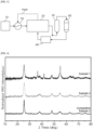
- FIG. 1 is a schematic process flowchart for describing a method of preparing an ammonia oxidation catalyst according to exemplary embodiments.
- a chromium compound and a titanium compound are mixed in an organic solvent to prepare a first mixture (step S10).
- the organic solvent may include an alcohol solvent.
- the organic solvent may include ethanol, propanol, isopropanol, butanol and the like.
- compatibility with precursor compounds may be further enhanced.
- a gelation reaction may be promoted even with the addition of a small amount of water.
- the organic solvent may include isopropanol.
- the chromium compound may include a nitrate, chloride, bromide, fluoride, hydroxide, carbonate, acetate, sulfate of chromium., etc.
- the chromium compound may include chromium nitrate.
- the titanium compound may include an alkoxide, nitrate, chloride, bromide, fluoride, hydroxide, carbonate, acetate, sulfate, etc. of titanium.
- the titanium compound may include titanium alkoxide.
- compatibility and affinity with the alcohol solvent may be further enhanced, and a crystal structure of titanium oxide may be formed through a gelation reaction and a heat treatment reaction.
- the titanium compound may include titanium tetraisopropoxide.
- the chromium compound and the titanium compound may be introduced together into the organic solvent, thereby allowing chromium to be efficiently incorporated into the crystal structure of titanium oxide.
- the titanium compound when the titanium compound is first introduced into the organic solvent and mixed, dispersibility of the first mixture is reduced, and chromium oxide having a crystal form separate from titanium oxide may be formed.
- a mixing speed of the chromium compound and the titanium compound in the organic solvent may be 300 rpm to 600 rpm, 350 rpm to 550 rpm, or 400 rpm to 500 rpm.
- the mixing process may be performed for 10 minutes to 240 minutes, 30 minutes to 180 minutes, or 60 minutes to 120 minutes.
- the temperature in the mixing process may be 2°C to 40°C.
- the chromium compound and the titanium compound may be added so that the chromium is added in an amount of 0.05 moles to 0.30 moles based on the total 1 mole of titanium and chromium on the elemental basis.
- the content of chromium may be 0.1 moles to 0.3 moles, 0.1 moles to 0.25 moles, or 0.1 moles to 0.2 moles based on the total 1 mole of titanium and chromium on the elemental basis.
- Water may be added to the first mixture to perform a sol-gel reaction for the second mixture.
- an amount of water added may be 1 to 30 parts by weight (“wt. parts”) based on 100 wt. parts of the organic solvent.
- wt. parts parts by weight
- the sol-gel reaction of the second mixture may be performed more efficiently, and the crystallinity of the ammonia oxidation catalyst may be easily controlled to a desired range by heat treatment to be described below.
- the amount of water added may be 1 wt. part to 25 wt. parts, 2 wt. parts to 25 wt. parts, or 2 wt. parts to 20 wt. parts based on 100 wt. parts of the organic solvent.
- the second mixture may have a pH of 5 or more.
- the second mixture may have a pH of 5 to 8, or 6 to 8.
- the titanium compound for example titanium oxide may be more efficiently converted into titanium oxide by gelation of the second mixture, thereby allowing chromium atoms to be easily substituted into the crystal lattice of the titanium oxide.
- nitric acid may be added to the first mixture to perform a sol-gel reaction for the second mixture.
- the second mixture is gelated to form a precursor solution (step S30).
- chromium atoms may be easily incorporated into the crystal lattice of titanium oxide through a heat treatment process to be described below. Accordingly, chromium may be substituted with titanium atoms of the titanium oxide crystal structure while suppressing the production of the crystal structure of chromium oxide.
- the temperature in the gelation process may be 15°C to 30°C.
- the gelation process may be performed at a rotation speed of 100 rpm to 500 rpm.
- the gelation process may be performed for 15 hours to 30 hours, or 20 hours to 30 hours.
- the gelation process may include a stirring process and an aging process performed on the second mixture.
- the second mixture may be stirred at a rotation speed of 100 rpm to 500 rpm, and then left in a constant-temperature device for a predetermined period of time.
- the stirring process may be performed at a temperature of 15°C to 30°C for 30 minutes to 4 hours, or 1 hour to 3 hours.
- the aging process may be performed at a temperature in a range of 15°C to 30°C. In one embodiment, the aging process may be performed for 10 hours to 30 hours, or 20 hours to 30 hours.
- An ammonia oxidation catalyst is prepared by performing heat treatment on the precursor solution (step S40).
- the precursor solution may be dried at a temperature of 70°C to 125°C, 80°C to 120°C, or 85°C to 110°C.
- the precursor solution may be dried, and subjected to calcination at a temperature of 350°C to 600°C, 400°C to 550°C, or 450°C to 550°C.
- FIG. 2 is a process flowchart for describing a catalyst system according to exemplary embodiments.
- the catalyst system according to embodiments of the present disclosure may include the ammonia oxidation catalyst according to the above-described embodiments.
- the catalyst system may include an ammonia decomposition reactor 20 and a catalyst unit 30.
- the catalyst unit 30 may include the ammonia oxidation catalyst.
- Ammonia may be decomposed in the ammonia decomposition reactor 20.
- ammonia (NH 3 ) may be decomposed to generate hydrogen (H 2 ) within the ammonia decomposition reactor 20.
- ammonia decomposition reaction a thermal decomposition reaction or a decomposition reaction using a reduction catalyst may be performed.
- the ammonia decomposition reactor 20 may also include an ammonia oxidation catalyst.
- the ammonia oxidation catalyst may be arranged in a stacked manner within the ammonia decomposition reactor 20. While the ammonia passes through the ammonia decomposition reactor 20, hydrogen gas may be generated.
- the ammonia decomposition reactor 20 may include a burner.
- the temperature in the ammonia decomposition reactor 20 may be increased by the burner, and heat energy required for ammonia decomposition may be supplied.
- the catalyst system may further include an ammonia supply unit 10.
- the ammonia supply unit 10 may be located in an upstream region of the ammonia decomposition reactor 20. Ammonia may be supplied to the ammonia decomposition reactor 20 through the ammonia supply unit 10.
- the ammonia supply unit 10 may include an ammonia storage tank.
- the ammonia gas supplied from the ammonia supply unit 10 may be decomposed into hydrogen (H 2 ) and nitrogen (N 2 ) in the ammonia decomposition reactor 20.
- a heat exchanger 50 may be arranged between the ammonia supply unit 10 and the ammonia decomposition reactor 20.
- the heat exchanger 50 may receive liquid ammonia from the ammonia supply unit 10 and vaporize the same. Accordingly, gaseous ammonia may be supplied to the ammonia decomposition reactor 20.
- the heat exchanger 50 may receive heat from a combustion gas discharged from the burner in the ammonia decomposition reactor 20. Heat flow between the ammonia decomposition reactor 20 and the heat exchanger 50 is indicated by dotted line arrows in FIGS. 2 and 3 .
- the catalyst unit 30 may be located in a downstream region of the ammonia decomposition reactor 20.
- the ammonia oxidation catalyst may be arranged in a stacked manner within the catalyst unit 30.
- a reaction gas and an oxygen gas may be supplied from the ammonia decomposition reactor 20 to the catalyst unit 30.
- the reaction gas may contain ammonia that has not reacted during the ammonia decomposition reaction.
- the ammonia and the oxygen gas may be caused to effect an oxidation reaction by the catalyst unit 30, thereby removing unreacted ammonia.
- the reaction gas supplied from the ammonia decomposition reactor 20 to the catalyst unit 30 may include hydrogen and nitrogen generated during the ammonia decomposition process.
- the ammonia oxidation catalyst may have high selectivity for ammonia thus to selectively remove only ammonia without consuming hydrogen generated during the ammonia decomposition process. Accordingly, the concentration of ammonia and the concentration of nitrogen oxides may be decreased while maintaining the concentration of hydrogen at a high level through the catalyst unit 30.
- the amount of oxygen gas supplied may be 8.9 or less, 6.7 or less, 4.4 or less, or 2.2 or less on a ppm basis relative to the ammonia concentration in the reaction gas. Even if the amount of oxygen gas supplied is small, the oxidation reaction for ammonia may be selectively promoted by the ammonia oxidation catalyst. Accordingly, the amount of oxygen gas supplied may be controlled to suppress the consumption of hydrogen gas and generation of nitrogen oxides while improving the ammonia removal efficiency.
- the reaction temperature in the ammonia decomposition reactor 20 may be 250°C to 500°C, 280°C to 450°C, or 300°C to 400°C. Within the above range, the consumption of hydrogen and generation of nitrogen oxides may be suppressed, and the ammonia removal efficiency may be further increased.
- an amount of nitrogen oxide (NOx) generated may be 200 ppm or less, which is measured under conditions where the reaction temperature is 200°C to 400°C and a concentration ratio of O 2 to NH 3 is 2.2 or more.
- the content of NOx generated by the oxidation reaction of the ammonia oxidation catalyst for ammonia and oxygen-containing gas under the conditions of 200°C to 400°C may be 150 ppm or less, or 120 ppm or less.
- the concentration ratio of O 2 to NH 3 in the reaction gas may be 2.2 to 8.9, 2.2 to 6.7, or 2.2 to 4.4 on the ppm basis.
- FIG. 3 is a process flowchart illustrating a catalyst system according to exemplary embodiments.
- the catalyst system may further include an ammonia adsorption unit 60.
- the ammonia adsorption unit 60 may be located in a downstream region of the ammonia decomposition reactor 20.
- the ammonia adsorption unit 60 may include an ammonia selective adsorbent. Accordingly, the ammonia adsorption unit 60 may selectively adsorb and remove unreacted ammonia. The ammonia concentration may be decreased by the ammonia adsorption unit 60, and high-purity hydrogen may be produced.
- the ammonia adsorption unit 60 may have a pressure swing adsorption (PSA) process or a temperature swing adsorption (TSA) process.
- PSA pressure swing adsorption
- TSA temperature swing adsorption
- the ammonia adsorption unit 60 may be located in a downstream region of the catalyst unit 30. Accordingly, ammonia remaining without being oxidized in the catalyst unit 30 may be removed by the ammonia adsorption unit.
- the ammonia adsorption unit 60 may also be located in an upstream region of the catalyst unit 30.
- the ammonia adsorption unit 60 may be located between the ammonia decomposition reactor 20 and the catalyst unit 30.
- the ammonia selective adsorbent may include a metal oxide including aluminum and silicon.
- the ammonia selective adsorbent may include aluminosilicate.
- the aluminosilicate may be carried or doped with an alkali metal ion (e.g., sodium ion, calcium ion, potassium ion, etc.).
- hydrogen gas purified in the catalyst unit 30 or the ammonia adsorption unit 60 may be supplied to a fuel cell 40.
- the fuel cell 40 may be a hydrogen fuel cell 40.
- the concentrations of ammonia and nitrogen oxides may be decreased without consuming hydrogen by the ammonia oxidation catalyst. Accordingly, the gas generated in the ammonia decomposition reactor 20 while passing through the catalyst unit 30 may be purified into high-purity hydrogen gas. Accordingly, a power generation efficiency of the fuel cell 40 may be further improved.
- the gas on which the reaction have been completed in the fuel cell 40 may be supplied back to the burner of the ammonia decomposition reactor 20. Then, the gas may be used as a heat source for the ammonia decomposition reaction.
- Chromium nitrate (Cr(NO 3 ) 3 ) and titanium isopropoxide (TTIP) were added to 250 g of isopropyl alcohol (IPA) and stirred at room temperature and a rotation speed of 450 rpm for 30 minutes to prepare a first mixture.
- the chromium nitrate and the titanium isopropoxide were added so that a molar ratio of chromium and titanium satisfied 30:70 and a mass of the final oxide catalyst after calcination was 6 g.
- the precursor solution was subjected to heat treatment at a temperature of 100°C for 24 hours to obtain a powder.
- the powder was subjected to heat treatment at a temperature of 500°C for 4 hours to prepare an ammonia oxidation catalyst.
- An ammonia oxidation catalyst was prepared in the same manner as in Example 1, except that the chromium nitrate and the titanium isopropoxide were added so that the molar ratio of chromium and titanium was 15:85.
- An ammonia oxidation catalyst was prepared in the same manner as in Example 1, except that the chromium nitrate and the titanium isopropoxide were added so that the molar ratio of chromium and titanium was 5:95.
- a second mixture was prepared by adding 10 mL of propylene oxide to the first mixture.
- the second mixture was stirred at a temperature of 25°C and a rotation speed of 450 rpm for 12 hours to obtain a precursor solution in the form of a gel.
- the precursor solution was subjected to heat treatment at a temperature of 100°C for 1 hour to obtain a powder.
- the powder was subj ected to heat treatment at a temperature of 400°C for 3 hours to prepare an ammonia oxidation catalyst.
- TiO 2 powder having a rutile crystalline phase was added to chromium nitrate hydrate (Cr(NO 3 ) 3 ⁇ 9H 2 O) and stirred for 2 hours. After drying at room temperature for 24 hours, the mixture was subj ected to heat treatment at a temperature of 500°C for 4 hours to produce a metal oxide in which chromium oxide (CrO x ) is carried on TiO 2 . The amount of Cr carried on TiO 2 was adjusted to 10% by weight ("wt. %").
- UV-Vis DRS analysis was performed on the metal oxides using a UV-Vis spectrometer (UV-VIS-NIR, Cary 5000) under conditions of 25°C and atmospheric pressure.
- the DRS absorption spectrum for the metal oxides was measured, and the energy band gap was calculated from the plot of ( ⁇ h ⁇ ) 1/2 according to the photon energy (hv).
- Crystal structures of the metal oxides of the examples and Comparative Example 1 were measured through X-ray diffraction analysis.
- XRD X-ray diffraction analysis
- FIG. 4 is an XRD graph of the metal oxides of the examples 1 and 2, and the comparative example 2.
- Example 2 and Comparative Example 1 In the case of Example 2 and Comparative Example 1, no crystal peak corresponding to Cr 2 O 3 appeared in the XRD spectrum of the metal oxides, and the metal oxides had crystal peaks corresponding to TiO 2 .
- Specific surface areas of the metal oxides of the examples and Comparative Examples 1 to 3 were measured with the BET method by nitrogen gas adsorption using a specific surface area measuring device (TriStar II Plus, MICROMERITCS).
- the metal oxides of the examples had higher specific surface areas than the metal oxides of the comparative examples.
- the metal oxide had a high specific surface area of 100 m 2 /g or more.
- ammonia oxidation reaction was evaluated using the reaction gas mixture.
- the flow rate of the reaction gas was controlled using a mass flow meter, and the space velocity of the reaction gas was 30,000 hr -1 .
- the gas concentration after the reaction was measured by QMS (Dycor 2000, Ametek), and the concentrations of NH 3 and NO were measured using a gas analyzer (Airwell 7+e, Tunable Diode Laser Absorption Spectroscopy, Korea Industrial Gas) and a gas analyzer (CLD82 S, ECO Physics), respectively.
- the temperature in the reactor was increased from 50°C to 450°C at a rate of temperature rise of 10°C/min, and the NH 3 concentration and NO concentration at each temperature were measured.
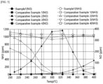
- FIG. 5 is a graph illustrating the gas concentration when using ammonia oxidation catalysts of Example 1 and comparative examples.
- the concentration of NH 3 was reduced to 10 ppm or less, and NO was generated at 10 ppm or less up to 300°C.
- the amount of NO generated at 400°C was measured to be 130 ppm or less.
- the NH 3 concentration and NO concentration after the reaction were measured while changing the ratio of O 2 /NH 3 in the reaction gas and the reaction temperature, respectively.
- the NH 3 concentration and NO concentration were measured when the gas concentration after the reaction reached a steady state.
- the ratio of O 2 /NH 3 was adjusted by changing only the concentrations of O 2 and NH 3 in the composition of the reaction gas shown in Table 3, and H 2 , He and N 2 were each controlled to satisfy the ratios shown in Table 3.
- FIGS. 6a and 6b are graphs illustrating the gas concentration when using an ammonia oxidation catalyst of Example 2.
- the NH 3 concentration and NO concentration according to the temperature were measured when the ratios of O 2 /NH 3 in the reaction gas were 2.2 and 4.4, respectively.
- FIG. 7 is a graph illustrating the gas concentration when using an ammonia oxidation catalyst of Example 1.
- Example 1 in the case of Example 1, the concentrations of NH 3 and NO in the gas after the reaction were low overall, and even when increasing the reaction temperature, the amount of NO generated was not increased.
- FIGS. 8a to 8d are graphs illustrating the gas concentration when using an ammonia oxidation catalyst of Comparative Example 2.
Landscapes
- Chemical & Material Sciences (AREA)
- Engineering & Computer Science (AREA)
- Chemical Kinetics & Catalysis (AREA)
- Organic Chemistry (AREA)
- Materials Engineering (AREA)
- General Chemical & Material Sciences (AREA)
- Environmental & Geological Engineering (AREA)
- Health & Medical Sciences (AREA)
- Analytical Chemistry (AREA)
- Oil, Petroleum & Natural Gas (AREA)
- Biomedical Technology (AREA)
- Combustion & Propulsion (AREA)
- Physics & Mathematics (AREA)
- Thermal Sciences (AREA)
- Inorganic Chemistry (AREA)
- Sustainable Energy (AREA)
- Sustainable Development (AREA)
- Life Sciences & Earth Sciences (AREA)
- Electrochemistry (AREA)
- General Health & Medical Sciences (AREA)
- Manufacturing & Machinery (AREA)
- Dispersion Chemistry (AREA)
- Catalysts (AREA)
- Fuel Cell (AREA)
Abstract
According to embodiments of the present disclosure, the ammonia oxidation catalyst includes a metal oxide including titanium and chromium, wherein an energy band gap of the metal oxide measured by UV-Vis DRS is less than 1.4 eV. The catalyst system according to embodiments of the present disclosure includes: an ammonia decomposition reactor; and a catalyst unit which is located in a downstream region of the ammonia decomposition reactor, and includes the above-described ammonia oxidation catalyst.
Description
- The present disclosure relates to a catalyst for ammonia oxidation ("an ammonia oxidation catalyst"), a method of preparing the ammonia oxidation catalyst and a catalyst system including the ammonia oxidation catalyst.
- Recently, due to problems of environmental pollution, techniques for reducing greenhouse gases or harmful gases in the atmosphere are being developed. Accordingly, there is a growing demand for a renewable alternative energy to replace the use of fossil fuels such as petroleum and coal. Hydrogen may be mainly used as one of the renewable alternative energy.
- Ammonia (NH3) is a carbon-free fuel and may efficiently store and transport hydrogen. For example, ammonia may be decomposed to generate hydrogen (H2) and nitrogen (N2), and the hydrogen generated from the ammonia may be supplied to a fuel cell and the like. However, in order to supply the hydrogen through a decomposition reaction of ammonia, an excess of ammonia may be required, and unreacted products that have not been converted into hydrogen among the supplied ammonia may be released into the atmosphere as exhaust gases.
- Since ammonia is a flammable and toxic gas, and may result in a secondary pollutant, it is necessary for the ammonia to be converted into an environmentally harmless component before it is released into the atmosphere. For example, a catalyst for selective ammonia oxidation may be used to efficiently remove residual ammonia while suppressing the generation of harmful gases. Accordingly, ammonia may be selectively decomposed into nitrogen (N2) and water (H2O).
- However, when a high concentration of oxygen is injected into a reaction for the selective oxidation of ammonia, the oxygen may react with hydrogen (H2) produced through the ammonia decomposition reaction, or react with nitrogen to generate nitrogen oxides (NOx) such as NO or NO2, etc. Since the hydrogen is consumed by the oxygen, an overall production efficiency of hydrogen may be decreased, and environmental pollution may occur due to the nitrogen oxides. Therefore, the development of an ammonia oxidation catalyst capable of efficiently removing ammonia while suppressing the consumption of hydrogen and generation of nitrogen oxides is required.
- An object of the present disclosure is to provide an ammonia oxidation catalyst which may selectively oxidize ammonia.
- Another object of the present disclosure is to provide a method of preparing an ammonia oxidation catalyst.
- In addition, another object of the present disclosure is to provide a catalyst system which includes the above-described ammonia oxidation catalyst.
- To achieve the above objects, a catalyst for ammonia oxidation according to embodiments the present disclosure includes a metal oxide including titanium and chromium, wherein an energy band gap of the metal oxide measured by UV-Vis diffuse reflectance spectroscopy (DRS) may be less than 1.4 eV.
- In some embodiments, the energy band gap of the metal oxide may be 0.2 eV or more and less than 1.4 eV.
- In some embodiments, a content of the chromium may be 0.10 to 0.30 moles based on a total 1 mole of titanium and chromium on an elemental basis.
- In some embodiments, the metal oxide may have a crystal structure. Preferably, the crystal structure may be a titanium oxide crystal structure. In some embodiments, the chromium may be doped into the titanium oxide crystal structure, and/or chromium may be present in the metal oxide by showing XRD peaks corresponding to Cr2O3. The XRD peaks corresponding to Cr2O3 may appear at 35° to 38° and 42° to 45° of 2 theta.
- In some embodiments, the metal oxide may include an anatase phase.
- In some embodiments, in an ammonia oxidation reaction by the ammonia oxidation catalyst, an amount of nitrogen oxide (NOx) generated may be 200 ppm or less when measured under conditions where a reaction temperature is 200°C to 400°C and a concentration ratio of O2 to NH3 is 2.2 or more.
- In a method of preparing a catalyst for ammonia oxidation according to embodiments the present disclosure, a chromium compound and a titanium compound may be mixed in an organic solvent to prepare a first mixture. Water may be added to the first mixture to prepare a second mixture. The second mixture may be gelated to prepare a precursor solution. The precursor solution may be subjected to heat treatment.
- In some embodiments, the organic solvent may include an alcohol solvent.
- In some embodiments, the second mixture may have a pH of 5 or more.
- In some embodiments, the step of performing heat treatment on the precursor solution may include: drying the precursor solution at a temperature of 70°C to 125°C; and performing calcination on the precursor solution at a temperature of 350°C to 600°C.
- In a further aspect, the present disclosure relates to the use of a catalyst comprising a metal oxide which comprises titanium and chromium, for an ammonia oxidation reaction in which ammonia reacts with oxygen (O2) to selectively produce the nitrogen gas (N2) gas, optionally further producing water (H2O), while a reaction between nitrogen and oxygen and a reaction between oxygen and hydrogen may be suppressed, such that an amount of nitrogen oxides generated may be decreased, preferably wherein the amount of nitrogen oxide (NOx) generated is 200 ppm or less.
- In embodiments concerning such use, the catalyst for ammonia oxidation is defined in accordance with the embodiments the present disclosure related to the catalyst for ammonia oxidation.
- A catalyst system according to embodiments the present disclosure includes: an ammonia decomposition reactor; and a catalyst unit which is located in a downstream region of the ammonia decomposition reactor and includes the ammonia oxidation catalyst according to the above-described embodiments.
- In some embodiments, the catalyst system may further include an ammonia supply unit which is located in an upstream region of the ammonia decomposition reactor.
- In some embodiments, the catalyst system may further include an ammonia adsorption unit which is located in a downstream region of the ammonia decomposition reactor and includes an ammonia selective adsorbent.
- In some embodiments, the ammonia adsorption unit may be located in a downstream region of the catalyst unit.
- In some embodiments, the catalyst system may include a fuel cell configured to receive hydrogen from the catalyst unit.
- The ammonia oxidation catalyst according to embodiments of the present disclosure may promote a selective reaction between oxygen and ammonia. Therefore, an ammonia removal efficiency may be improved even under conditions of low concentration of oxygen while suppressing the consumption of hydrogen and generation of nitrogen oxides.
- In the method of preparing the ammonia oxidation catalyst according to embodiments of the present disclosure, chromium oxide and titanium alkoxide are gelated under a predetermined mixing condition. Accordingly, chromium may be substituted with titanium in a crystal lattice of titanium dioxide, thus to suppress the generation of chromium oxides (CrOx).
- The catalyst system according to embodiments of the present disclosure includes the ammonia oxidation catalyst. Thereby, a supply amount of oxygen may be reduced, and the generation of nitrogen oxides may be suppressed, thus to provide a high-purity hydrogen gas to the fuel cell.
- The above and other objects, features and other advantages of the present invention will be more clearly understood from the following detailed description taken in conjunction with the accompanying drawings, in which:
-
FIG. 1 is a schematic process flowchart for describing a method of preparing an ammonia oxidation catalyst according to exemplary embodiments; -
FIG. 2 is a process flowchart for describing a catalyst system according to exemplary embodiments; -
FIG. 3 is a process flowchart for describing a catalyst system according to exemplary embodiments; -
FIG. 4 is an XRD graph of a metal oxide according to examples; -
FIG. 5 is a graph illustrating the gas concentration when using ammonia oxidation catalysts of Example 1 and comparative examples; -
FIGS. 6a and 6b are graphs illustrating the gas concentration when using an ammonia oxidation catalyst of Example 2; -
FIG. 7 is a graph illustrating the gas concentration when using an ammonia oxidation catalyst of Example 1; and -
FIGS. 8a to 8d are graphs illustrating the gas concentration when using an ammonia oxidation catalyst of Comparative Example 2. - According to embodiments of the present disclosure, there is provided an ammonia oxidation catalyst.
- According to embodiments of the present disclosure, there is provided a catalyst system including the ammonia oxidation catalyst.
- Hereinafter, embodiments of the present disclosure will be described in more detail.
- An ammonia oxidation catalyst according to embodiments of the present disclosure includes a metal oxide including titanium and chromium. The ammonia oxidation catalyst may selectively promote an oxidation reaction of ammonia (NH3) to convert the ammonia into a nitrogen gas. The ammonia oxidation reaction refers to a reaction in which ammonia reacts with oxygen (O2) to produce the nitrogen gas. Besides nitrogen (N2) gas, the ammonia oxidation reaction may produce water (H2O).
- The metal oxide may have crystal structure, in particular a titanium oxide crystal structure. Chromium may be doped into the titanium oxide within the metal oxide. For example, some of titanium atoms may be substituted with chromium atoms within the crystal structure of the titanium oxide, or chromium atoms may be positioned at oxygen vacancies, which are positions where oxygen is missed in the crystal structure of the titanium oxide, or chromium atoms may be positioned in empty spaces within the lattices of titanium and oxygen, thereby resulting in interstitial doping.
- Accordingly, stability of the ammonia oxidation catalyst may be improved, and specific surface area and active site of the catalyst may be increased, thereby further promoting the oxidation reaction of ammonia.
- According to exemplary embodiments, the metal oxide may have a crystal structure of titanium dioxide (TiO2). For example, the crystal lattice of the metal oxide may be substantially the same as the crystal lattice of titanium dioxide.
- In some embodiments, chromium may be incorporated into the crystal structure of the titanium dioxide. For example, some of the titanium atoms in the crystal lattice of the titanium dioxide may be substituted with chromium atoms. When the ammonia oxidation catalyst has the crystal structure of titanium dioxide and includes chromium in the crystal structure, both the structural stability and the catalytic activity may be improved.
- Since the ammonia oxidation catalyst according to exemplary embodiments has the above-described crystal structure, the ammonia selectivity and the ammonia removal efficiency may be increased. Accordingly, the ammonia removal efficiency may be improved even under conditions of low concentration of oxygen, and the consumption of hydrogen due to high concentration of oxygen may be prevented. In addition, a reaction between nitrogen and oxygen may be suppressed, such that an amount of nitrogen oxides generated may be decreased.
- An energy band gap of the metal oxide is less than 1.4 eV. For example, the energy band gap of the metal oxide may be 0.2 eV or more and less than 1.4 eV. The energy band gap of the metal oxide may be measured by UV-Vis diffuse reflectance spectroscopy (UV-Vis DRS).
- The energy band gap may be measured as an indicator of a degree where chromium atoms are substituted or doped into the crystal structure of the titanium dioxide. For example, even if the contents of chromium atoms included in the metal oxide are the same, crystal forms of the metal oxide may be different from each other depending on whether the chromium atoms exist in the crystal lattice of titanium oxide (TiOx) and when the chromium atoms exist in the crystal structure of chromium oxide (CrOx, such as Cr2O3). Accordingly, the catalytic activity and properties of the ammonia oxidation catalyst may vary depending on the crystal form of the metal oxide.
- A new valence band is provided due to a change in an electronic structure caused by the chromium (Cr) incorporated in the crystal structure of the titanium oxide, and the energy band gap of the metal oxide may be shifted to a lower value.
- The ammonia oxidation catalyst may include a metal oxide having the energy band gap within the above range, such that the ammonia oxidation reaction and ammonia selectivity may be improved. Accordingly, the selective oxidation reaction for ammonia may be promoted even at a low oxygen partial pressure, and the consumption of hydrogen and the amount of the nitrogen oxides generated may be decreased.
- In one embodiment, the energy band gap of the metal oxide may be 0.2 eV or more and less than 1.4 eV, or 0.5 eV to 1.3 eV, or 0.8 eV to 1.3 eV. Within the above range, a ratio of the chromium oxide in the crystal structure of the metal oxide may be reduced, and the reaction selectivity and reaction efficiency for ammonia may be further enhanced.
- In some embodiments, a peak position of a binding energy of Cr in the metal oxide may be higher than the peak position of the binding energy of Cr in the chromium oxide (e.g., Cr2O3). The peak position may mean the peak median value.
- For example, the position of a peak in the Cr 2p energy spectrum of the metal oxide measured by X-ray photoelectron spectroscopy (XPS) measurement may be higher by 0.5 eV or more, for example, 0.5 eV to 1.5 eV, than the position of the peak in the Cr 2p spectrum of the Cr2O3.
- In some embodiments, the metal oxide may not include chromium oxide (CrOx). For example, the metal oxide may not have a crystal structure of Cr2O3. Accordingly, the ammonia selectivity may be further enhanced while further promoting the ammonia oxidation reaction of the ammonia oxidation catalyst. Accordingly, only ammonia may be selectively removed while suppressing the reaction between oxygen and hydrogen.
- For example, the crystal structure of the metal oxide may be measured through X-ray diffraction (XRD) analysis. In the XRD graph of the metal oxide, no peak may be observed within the wavenumber range corresponding to Cr2O3. Optionally, one or more peaks corresponding to Cr2O3 may be observed within the wavenumber range in the XRD graph of the metal oxide. The XRD peaks corresponding to Cr2O3 may appear at 35° to 38° and 42° to 45° of 2 theta.
- In some embodiments, a content of the chromium may be 0.05 moles to 0.30 moles based on a total 1 mole of titanium and chromium on an elemental basis. Within the above range, the ammonia selectivity may be further improved, and the reaction of hydrogen or nitrogen with oxygen may be further suppressed. Accordingly, the ammonia removal efficiency may be improved while suppressing the consumption of hydrogen and generation of nitrogen oxides.
- In one embodiment, the content of the chromium may be 0.10 moles to 0.30 moles, 0.10 moles to 0.25 moles, or 0.10 moles to 0.20 moles based on the total 1 mole of titanium and chromium on the elemental basis. Within the above range, the reactivity for ammonia in a high-temperature environment may be further enhanced while the ammonia oxidation catalyst has high activity.
- In some embodiments, the metal oxide may have a crystalline structure. For example, the metal oxide may not include, i.e. exclude, an amorphous structure.
- In one embodiment, the metal oxide may have an anatase phase. For example, an anatase phase may mean an anatase crystal phase. Accordingly, the stability and activity of the ammonia oxidation catalyst may be further improved.
- In one embodiment, the metal oxide may be represented by
Formula 1 below.
[Formula 1] CrxTi1-xO2
- In the
Formula 1, x may be 0.05 to 0.30, 0.1 to 0.3, 0.1 to 0.25, or 0.1 to 0.2. - In some embodiments, the metal oxide may have a specific surface area of, for example, 50 m2/g to 150 m2/g or 80 to 130 m2/g. The specific surface area may be measured through the Brunauer-Emmett-Teller (BET) method by nitrogen (N2) adsorption.
- In one embodiment, the metal oxide may have a specific surface area of 85 m2/g to 125 m2/g, 90 m2/g to 120 m2/g, or 100 m2/g to 120 m2/g. Within the above range, the oxidation reaction and selectivity of ammonia may be further improved.
-
FIG. 1 is a schematic process flowchart for describing a method of preparing an ammonia oxidation catalyst according to exemplary embodiments. - Referring to
FIG. 1 , a chromium compound and a titanium compound are mixed in an organic solvent to prepare a first mixture (step S10). - In some embodiments, the organic solvent may include an alcohol solvent. For example, the organic solvent may include ethanol, propanol, isopropanol, butanol and the like. When the organic solvent includes the alcohol solvent, compatibility with precursor compounds may be further enhanced. In addition, when using the alcohol solvent as a base solvent, a gelation reaction may be promoted even with the addition of a small amount of water.
- In one embodiment, the organic solvent may include isopropanol.
- In some embodiments, the chromium compound may include a nitrate, chloride, bromide, fluoride, hydroxide, carbonate, acetate, sulfate of chromium., etc.
- In one embodiment, the chromium compound may include chromium nitrate.
- In some embodiments, the titanium compound may include an alkoxide, nitrate, chloride, bromide, fluoride, hydroxide, carbonate, acetate, sulfate, etc. of titanium.
- In one embodiment, the titanium compound may include titanium alkoxide. When including the titanium alkoxide as the titanium compound, compatibility and affinity with the alcohol solvent may be further enhanced, and a crystal structure of titanium oxide may be formed through a gelation reaction and a heat treatment reaction.
- For example, the titanium compound may include titanium tetraisopropoxide.
- The chromium compound and the titanium compound may be introduced together into the organic solvent, thereby allowing chromium to be efficiently incorporated into the crystal structure of titanium oxide. For example, when the titanium compound is first introduced into the organic solvent and mixed, dispersibility of the first mixture is reduced, and chromium oxide having a crystal form separate from titanium oxide may be formed.
- In one embodiment, a mixing speed of the chromium compound and the titanium compound in the organic solvent may be 300 rpm to 600 rpm, 350 rpm to 550 rpm, or 400 rpm to 500 rpm.
- In one embodiment, the mixing process may be performed for 10 minutes to 240 minutes, 30 minutes to 180 minutes, or 60 minutes to 120 minutes.
- In one embodiment, the temperature in the mixing process may be 2°C to 40°C.
- In some embodiments, the chromium compound and the titanium compound may be added so that the chromium is added in an amount of 0.05 moles to 0.30 moles based on the total 1 mole of titanium and chromium on the elemental basis.
- In one embodiment, among the chromium compound and the titanium compound, the content of chromium may be 0.1 moles to 0.3 moles, 0.1 moles to 0.25 moles, or 0.1 moles to 0.2 moles based on the total 1 mole of titanium and chromium on the elemental basis.
- Water is added to the first mixture to prepare a second mixture (step S20).
- Water may be added to the first mixture to perform a sol-gel reaction for the second mixture.
- In some embodiments, an amount of water added may be 1 to 30 parts by weight ("wt. parts") based on 100 wt. parts of the organic solvent. Within the above range, the sol-gel reaction of the second mixture may be performed more efficiently, and the crystallinity of the ammonia oxidation catalyst may be easily controlled to a desired range by heat treatment to be described below.
- In one embodiment, the amount of water added may be 1 wt. part to 25 wt. parts, 2 wt. parts to 25 wt. parts, or 2 wt. parts to 20 wt. parts based on 100 wt. parts of the organic solvent.
- In some embodiments, the second mixture may have a pH of 5 or more. For example, the second mixture may have a pH of 5 to 8, or 6 to 8. Within the above range, the titanium compound, for example titanium oxide may be more efficiently converted into titanium oxide by gelation of the second mixture, thereby allowing chromium atoms to be easily substituted into the crystal lattice of the titanium oxide.
- In one embodiment, nitric acid may be added to the first mixture to perform a sol-gel reaction for the second mixture.
- The second mixture is gelated to form a precursor solution (step S30).
- As the second mixture is gelated, chromium atoms may be easily incorporated into the crystal lattice of titanium oxide through a heat treatment process to be described below. Accordingly, chromium may be substituted with titanium atoms of the titanium oxide crystal structure while suppressing the production of the crystal structure of chromium oxide.
- In one embodiment, the temperature in the gelation process may be 15°C to 30°C.
- In one embodiment, the gelation process may be performed at a rotation speed of 100 rpm to 500 rpm.
- In one embodiment, the gelation process may be performed for 15 hours to 30 hours, or 20 hours to 30 hours.
- In some embodiments, the gelation process may include a stirring process and an aging process performed on the second mixture.
- For example, the second mixture may be stirred at a rotation speed of 100 rpm to 500 rpm, and then left in a constant-temperature device for a predetermined period of time.
- In one embodiment, the stirring process may be performed at a temperature of 15°C to 30°C for 30 minutes to 4 hours, or 1 hour to 3 hours.
- In one embodiment, the aging process may be performed at a temperature in a range of 15°C to 30°C. In one embodiment, the aging process may be performed for 10 hours to 30 hours, or 20 hours to 30 hours.
- An ammonia oxidation catalyst is prepared by performing heat treatment on the precursor solution (step S40).
- In one embodiment, the precursor solution may be dried at a temperature of 70°C to 125°C, 80°C to 120°C, or 85°C to 110°C.
- In one embodiment, the precursor solution may be dried, and subjected to calcination at a temperature of 350°C to 600°C, 400°C to 550°C, or 450°C to 550°C.
-
FIG. 2 is a process flowchart for describing a catalyst system according to exemplary embodiments. - The catalyst system according to embodiments of the present disclosure may include the ammonia oxidation catalyst according to the above-described embodiments.
- The catalyst system may include an
ammonia decomposition reactor 20 and acatalyst unit 30. Thecatalyst unit 30 may include the ammonia oxidation catalyst. - Ammonia may be decomposed in the
ammonia decomposition reactor 20. For example, ammonia (NH3) may be decomposed to generate hydrogen (H2) within theammonia decomposition reactor 20. - As the ammonia decomposition reaction, a thermal decomposition reaction or a decomposition reaction using a reduction catalyst may be performed.
- In one embodiment, the
ammonia decomposition reactor 20 may also include an ammonia oxidation catalyst. The ammonia oxidation catalyst may be arranged in a stacked manner within theammonia decomposition reactor 20. While the ammonia passes through theammonia decomposition reactor 20, hydrogen gas may be generated. - In one embodiment, the
ammonia decomposition reactor 20 may include a burner. The temperature in theammonia decomposition reactor 20 may be increased by the burner, and heat energy required for ammonia decomposition may be supplied. - The catalyst system may further include an
ammonia supply unit 10. Theammonia supply unit 10 may be located in an upstream region of theammonia decomposition reactor 20. Ammonia may be supplied to theammonia decomposition reactor 20 through theammonia supply unit 10. In one embodiment, theammonia supply unit 10 may include an ammonia storage tank. - For example, the ammonia gas supplied from the
ammonia supply unit 10 may be decomposed into hydrogen (H2) and nitrogen (N2) in theammonia decomposition reactor 20. - In some embodiments, a
heat exchanger 50 may be arranged between theammonia supply unit 10 and theammonia decomposition reactor 20. Theheat exchanger 50 may receive liquid ammonia from theammonia supply unit 10 and vaporize the same. Accordingly, gaseous ammonia may be supplied to theammonia decomposition reactor 20. - In one embodiment, the
heat exchanger 50 may receive heat from a combustion gas discharged from the burner in theammonia decomposition reactor 20. Heat flow between theammonia decomposition reactor 20 and theheat exchanger 50 is indicated by dotted line arrows inFIGS. 2 and3 . - The
catalyst unit 30 may be located in a downstream region of theammonia decomposition reactor 20. The ammonia oxidation catalyst may be arranged in a stacked manner within thecatalyst unit 30. - A reaction gas and an oxygen gas may be supplied from the
ammonia decomposition reactor 20 to thecatalyst unit 30. The reaction gas may contain ammonia that has not reacted during the ammonia decomposition reaction. The ammonia and the oxygen gas may be caused to effect an oxidation reaction by thecatalyst unit 30, thereby removing unreacted ammonia. - In one embodiment, the reaction gas supplied from the
ammonia decomposition reactor 20 to thecatalyst unit 30 may include hydrogen and nitrogen generated during the ammonia decomposition process. The ammonia oxidation catalyst may have high selectivity for ammonia thus to selectively remove only ammonia without consuming hydrogen generated during the ammonia decomposition process. Accordingly, the concentration of ammonia and the concentration of nitrogen oxides may be decreased while maintaining the concentration of hydrogen at a high level through thecatalyst unit 30. - In one embodiment, the amount of oxygen gas supplied may be 8.9 or less, 6.7 or less, 4.4 or less, or 2.2 or less on a ppm basis relative to the ammonia concentration in the reaction gas. Even if the amount of oxygen gas supplied is small, the oxidation reaction for ammonia may be selectively promoted by the ammonia oxidation catalyst. Accordingly, the amount of oxygen gas supplied may be controlled to suppress the consumption of hydrogen gas and generation of nitrogen oxides while improving the ammonia removal efficiency.
- In one embodiment, the reaction temperature in the
ammonia decomposition reactor 20 may be 250°C to 500°C, 280°C to 450°C, or 300°C to 400°C. Within the above range, the consumption of hydrogen and generation of nitrogen oxides may be suppressed, and the ammonia removal efficiency may be further increased. - In one embodiment, in the ammonia oxidation reaction using the ammonia oxidation catalyst, an amount of nitrogen oxide (NOx) generated may be 200 ppm or less, which is measured under conditions where the reaction temperature is 200°C to 400°C and a concentration ratio of O2 to NH3 is 2.2 or more.
- For example, the content of NOx generated by the oxidation reaction of the ammonia oxidation catalyst for ammonia and oxygen-containing gas under the conditions of 200°C to 400°C may be 150 ppm or less, or 120 ppm or less. The concentration ratio of O2 to NH3 in the reaction gas may be 2.2 to 8.9, 2.2 to 6.7, or 2.2 to 4.4 on the ppm basis.
-
FIG. 3 is a process flowchart illustrating a catalyst system according to exemplary embodiments. - Referring to
FIG. 3 , the catalyst system may further include anammonia adsorption unit 60. Theammonia adsorption unit 60 may be located in a downstream region of theammonia decomposition reactor 20. - The
ammonia adsorption unit 60 may include an ammonia selective adsorbent. Accordingly, theammonia adsorption unit 60 may selectively adsorb and remove unreacted ammonia. The ammonia concentration may be decreased by theammonia adsorption unit 60, and high-purity hydrogen may be produced. - In some embodiments, the
ammonia adsorption unit 60 may have a pressure swing adsorption (PSA) process or a temperature swing adsorption (TSA) process. - In some embodiments, the
ammonia adsorption unit 60 may be located in a downstream region of thecatalyst unit 30. Accordingly, ammonia remaining without being oxidized in thecatalyst unit 30 may be removed by the ammonia adsorption unit. - In some embodiments, the
ammonia adsorption unit 60 may also be located in an upstream region of thecatalyst unit 30. For example, theammonia adsorption unit 60 may be located between theammonia decomposition reactor 20 and thecatalyst unit 30. - In one embodiment, the ammonia selective adsorbent may include a metal oxide including aluminum and silicon. For example, the ammonia selective adsorbent may include aluminosilicate. In one embodiment, the aluminosilicate may be carried or doped with an alkali metal ion (e.g., sodium ion, calcium ion, potassium ion, etc.).
- According to exemplary embodiments, hydrogen gas purified in the
catalyst unit 30 or theammonia adsorption unit 60 may be supplied to afuel cell 40. For example, thefuel cell 40 may be ahydrogen fuel cell 40. - The concentrations of ammonia and nitrogen oxides may be decreased without consuming hydrogen by the ammonia oxidation catalyst. Accordingly, the gas generated in the
ammonia decomposition reactor 20 while passing through thecatalyst unit 30 may be purified into high-purity hydrogen gas. Accordingly, a power generation efficiency of thefuel cell 40 may be further improved. - In one embodiment, the gas on which the reaction have been completed in the
fuel cell 40 may be supplied back to the burner of theammonia decomposition reactor 20. Then, the gas may be used as a heat source for the ammonia decomposition reaction. - Chromium nitrate (Cr(NO3)3) and titanium isopropoxide (TTIP) were added to 250 g of isopropyl alcohol (IPA) and stirred at room temperature and a rotation speed of 450 rpm for 30 minutes to prepare a first mixture. The chromium nitrate and the titanium isopropoxide were added so that a molar ratio of chromium and titanium satisfied 30:70 and a mass of the final oxide catalyst after calcination was 6 g.
- 12 g of deionized water was added to the first mixture to prepare a second mixture. The second mixture was stirred at a temperature of 25°C and a rotation speed of 450 rpm for 2 hours, and stored at 25°C for 24 hours to obtain a precursor solution in the form of a gel.
- The precursor solution was subjected to heat treatment at a temperature of 100°C for 24 hours to obtain a powder. The powder was subjected to heat treatment at a temperature of 500°C for 4 hours to prepare an ammonia oxidation catalyst.
- An ammonia oxidation catalyst was prepared in the same manner as in Example 1, except that the chromium nitrate and the titanium isopropoxide were added so that the molar ratio of chromium and titanium was 15:85.
- An ammonia oxidation catalyst was prepared in the same manner as in Example 1, except that the chromium nitrate and the titanium isopropoxide were added so that the molar ratio of chromium and titanium was 5:95.
- 6 g of chromium nitrate (Cr(NO3)3) was added to 100 mL of isopropyl alcohol (IPA) and stirred at room temperature and a rotation speed of 450 rpm for 30 minutes to prepare a first mixture.
- A second mixture was prepared by adding 10 mL of propylene oxide to the first mixture. The second mixture was stirred at a temperature of 25°C and a rotation speed of 450 rpm for 12 hours to obtain a precursor solution in the form of a gel.
- The precursor solution was subjected to heat treatment at a temperature of 100°C for 1 hour to obtain a powder. The powder was subj ected to heat treatment at a temperature of 400°C for 3 hours to prepare an ammonia oxidation catalyst.
- TiO2 powder having a rutile crystalline phase was added to chromium nitrate hydrate (Cr(NO3)3·9H2O) and stirred for 2 hours. After drying at room temperature for 24 hours, the mixture was subj ected to heat treatment at a temperature of 500°C for 4 hours to produce a metal oxide in which chromium oxide (CrOx) is carried on TiO2. The amount of Cr carried on TiO2 was adjusted to 10% by weight ("wt. %").
- An ammonia oxidation catalyst in which 2 wt. % of Pt is carried on an Al2O3 carrier was prepared.
- UV-Vis DRS analysis was performed on the metal oxides using a UV-Vis spectrometer (UV-VIS-NIR, Cary 5000) under conditions of 25°C and atmospheric pressure. The DRS absorption spectrum for the metal oxides was measured, and the energy band gap was calculated from the plot of (αhν)1/2 according to the photon energy (hv).
- Measurement results are shown in Table 1 below.
[TABLE 1] Cr:Ti (molar ratio) Energy band gap (eV) Example 1 30:70 0.8 Example 2 15:85 1.3 Comparative Example 1 5:95 1.4 Comparative Example 2 100:0 3.2 Comparative Example 3 14.5:85.5 2.4 - Crystal structures of the metal oxides of the examples and Comparative Example 1 were measured through X-ray diffraction analysis.
- Specifically, the crystal structures of the composite oxides were measured by X-ray diffraction analysis (XRD) under conditions of 300 mA current, 50 kV voltage, Cu Kα radiation of wavelength (1.5428 Å), scanning speed of 5 degree min-1, and 2θ = 10° to 80°.
-
FIG. 4 is an XRD graph of the metal oxides of the examples 1 and 2, and the comparative example 2. - Referring to
FIG. 4 , in the case of Example 1, peaks corresponding to Cr2O3 appeared at 35° to 38° and 42° to 45°. - In the case of Example 2 and Comparative Example 1, no crystal peak corresponding to Cr2O3 appeared in the XRD spectrum of the metal oxides, and the metal oxides had crystal peaks corresponding to TiO2.
- Specific surface areas of the metal oxides of the examples and Comparative Examples 1 to 3 were measured with the BET method by nitrogen gas adsorption using a specific surface area measuring device (TriStar II Plus, MICROMERITCS).
- Measurement results are shown in Table 2 below.
[TABLE 2] Specific surface area (m2/g) Example 1 87 Example 2 115 Comparative Example 1 85 Comparative Example 2 27 Comparative Example 3 65 - Referring to Table 2 above, the metal oxides of the examples had higher specific surface areas than the metal oxides of the comparative examples. In the case of Example 2, the metal oxide had a high specific surface area of 100 m2/g or more.
- 2.5 g of the ammonia catalyst was put into a fixed bed reactor, and subjected to reduction treatment with a mixture of H2 and N2 gas (
H 2 10% by volume) at a temperature of 400°C for 1 hour. - Then, ammonia oxidation reaction was evaluated using the reaction gas mixture. The flow rate of the reaction gas was controlled using a mass flow meter, and the space velocity of the reaction gas was 30,000 hr-1.
- The concentrations of oxygen and ammonia were adjusted to be about 2,300 ppm and about 1,050 ppm, respectively. The compositions of O2, NH3, H2, He, and N2 in the reaction gas were controlled as shown in Table 3 below.
[TABLE 3] Item Concentration O2 2,344 ppm NH3 1,057 ppm H2 11.5% He 0.6% N2 87.6% - The gas concentration after the reaction was measured by QMS (Dycor 2000, Ametek), and the concentrations of NH3 and NO were measured using a gas analyzer (Airwell 7+e, Tunable Diode Laser Absorption Spectroscopy, Korea Industrial Gas) and a gas analyzer (CLD82 S, ECO Physics), respectively.
- The temperature in the reactor was increased from 50°C to 450°C at a rate of temperature rise of 10°C/min, and the NH3 concentration and NO concentration at each temperature were measured.
- Evaluation results are shown in Table 4 and
FIG. 5 .[TABLE 4] Temperat ure (°C) Example 1 Comparative Example 1 Comparative Example 2 Comparative Example 3 Comparative Example 4 NH3 concent ration (ppm) NO concent ration (ppm) NH3 concent ration (ppm) NO concent ration (ppm) NH3 concent ration (ppm) NO concent ration (ppm) NH3 concent ration (ppm) NO concent ration (ppm) NH3 concent ration (ppm) NO concent ration (ppm) 200 700 0 1130 1 975 22 1012 0 1068 0 225 572 0 1091 2 896 48 999 0 1068 0 250 382 1 1041 4 659 119 988 0 1068 0 275 118 4 968 5 269 251 982 0 1064 0 300 18 8 932 3 57 378 993 0 1063 0 325 7 17 943 1 23 389 1004 0 1059 0 350 5 39 998 0 56 198 1009 0 1054 0 375 4 72 1012 0 119 31 1012 0 1045 0 400 3 122 1008 0 171 0 1012 0 1041 0 -
FIG. 5 is a graph illustrating the gas concentration when using ammonia oxidation catalysts of Example 1 and comparative examples. - Referring to
FIG. 5 , in the case of Example 1, the concentration of NH3 was reduced to 10 ppm or less, and NO was generated at 10 ppm or less up to 300°C. In addition, the amount of NO generated at 400°C was measured to be 130 ppm or less. - In the case of Comparative Example 1, the content of chromium, which is an active metal, was low, such that ammonia did not react with oxygen, and the concentration of ammonia was not substantially decreased.
- In the case of Comparative Example 2, the concentration of NH3 was reduced to 23 ppm, but the amount of NO generated was increased to 300 ppm or more. In addition, when increasing the temperature to 300°C or higher, the concentration of NH3 was increased due to the depletion of oxygen caused by the reaction between oxygen and hydrogen.
- In the case of Comparative Example 3, all the oxygen injected for the oxidation of ammonia in the chromium oxide carried on TiO2 reacted with hydrogen to be consumed, and ammonia was not removed due to the depletion of oxygen.
- In the case of Comparative Example 4, ammonia did not react with oxygen, and the ammonia concentration was measured to be high in all temperature ranges.
- For the examples and Comparative Example 2, the NH3 concentration and NO concentration after the reaction were measured while changing the ratio of O2/NH3 in the reaction gas and the reaction temperature, respectively. The NH3 concentration and NO concentration were measured when the gas concentration after the reaction reached a steady state.
- The ratio of O2/NH3 was adjusted by changing only the concentrations of O2 and NH3 in the composition of the reaction gas shown in Table 3, and H2, He and N2 were each controlled to satisfy the ratios shown in Table 3.
-
FIGS. 6a and 6b are graphs illustrating the gas concentration when using an ammonia oxidation catalyst of Example 2. - Specifically, the NH3 concentration and NO concentration according to the temperature were measured when the ratios of O2/NH3 in the reaction gas were 2.2 and 4.4, respectively.
- Referring to
FIGS. 6a and 6b , in the case of Example 2, even when the ratio of O2 and the reaction temperature were increased, the concentrations of NH3 and NO in the gas after the reaction were low. -
FIG. 7 is a graph illustrating the gas concentration when using an ammonia oxidation catalyst of Example 1. - Referring to
FIG. 7 , in the case of Example 1, the concentrations of NH3 and NO in the gas after the reaction were low overall, and even when increasing the reaction temperature, the amount of NO generated was not increased. -
FIGS. 8a to 8d are graphs illustrating the gas concentration when using an ammonia oxidation catalyst of Comparative Example 2. - Specifically, when the ratios of O2/NH3 in the reaction gas were 2.2, 4.4, 6.7, and 8.9, respectively, the NH3 concentration and NO concentration were measured according to the temperature.
- Referring to
FIGS. 8a to 8d , in the case of Comparative Example 2, the concentrations of NH3 and NO in the gas after the reaction were high overall. In addition, as the reaction temperature was increased or the ratio of O2 was increased, the amount of NO generated was greatly increased.
Claims (15)
- A catalyst for ammonia oxidation comprising a metal oxide which comprises titanium and chromium,
wherein an energy band gap of the metal oxide measured by UV-Vis diffuse reflectance spectroscopy (DRS) is less than 1.4 eV. - The catalyst for ammonia oxidation according to claim 1, wherein the energy band gap of the metal oxide is 0.2 eV or more and less than 1.4 eV.
- The catalyst for ammonia oxidation according to claim 1 or 2, wherein a content of the chromium is 0.10 to 0.30 moles based on a total 1 mole of titanium and chromium on an elemental basis.
- The catalyst for ammonia oxidation according to any one of claims 1 to 3, wherein the metal oxide has a crystalline structure, preferably the metal oxide has a titanium oxide crystal structure, and the chromium is doped into the titanium oxide crystal structure, optionally wherein chromium is present in the metal oxide in a form of showing XRD peaks corresponding to Cr2O3 which appear at 35° to 38° and 42° to 45° 2theta.
- The catalyst for ammonia oxidation according to any one of claims 1 to 4, wherein the metal oxide comprises an anatase phase.
- The catalyst for ammonia oxidation according to any one of claims 1 to 5, wherein, when the ammonia oxidation catalyst is used in an ammonia oxidation reaction, an amount of nitrogen oxide (NOx) generated is 200 ppm or less when measured under conditions where a reaction temperature is 200°C to 400°C, and a concentration ratio of O2 to NH3 is 2.2 or more.
- A method of preparing a catalyst for ammonia oxidation, the method comprising:mixing a chromium compound and a titanium compound in an organic solvent to prepare a first mixture;adding water to the first mixture to prepare a second mixture;gelating the second mixture to prepare a precursor solution; andperforming heat treatment on the precursor solution.
- The method according to claim 7, wherein the organic solvent comprises an alcohol solvent, and/or wherein the titanium compound is titanium alkoxide.
- The method according to claim 7 or 8, wherein the second mixture has a pH of 5 or more, and/or wherein the chromium compound and the titanium compound are introduced together into the organic solvent.
- The method according to any one of claims 7 to 9, wherein the step of performing heat treatment on the precursor solution comprises: drying the precursor solution at a temperature of 70°C to 125°C; and performing calcination on the precursor solution at a temperature of 350°C to 600°C.
- Use of a catalyst comprising a metal oxide which comprises titanium and chromium, wherein an energy band gap of the metal oxide measured by UV-Vis diffuse reflectance spectroscopy (DRS) is less than 1.4 eV, for ammonia oxidation, preferably wherein the amount of nitrogen oxide (NOx) generated is 200 ppm or less.
- A catalyst system comprising:an ammonia decomposition reactor (20); anda catalyst unit (30) which is located in a downstream region of the ammonia decomposition reactor (20) and comprises the ammonia oxidation catalyst according to any one of claims 1 to 6.
- The catalyst system according to claim 12, further comprising an ammonia supply unit (10) which is located in an upstream region of the ammonia decomposition reactor (20).
- The catalyst system according to claim 12 or 13, further comprising an ammonia adsorption unit (60) which is located in a downstream region of the ammonia decomposition reactor (20) and comprises an ammonia selective adsorbent,
preferably wherein the ammonia adsorption unit (60) is located in a downstream region or upstream region of the catalyst unit (30). - The catalyst system according to any one of claims 12 to 14, comprising a fuel cell (40) configured to receive hydrogen from the catalyst unit (30).
Applications Claiming Priority (1)
| Application Number | Priority Date | Filing Date | Title |
|---|---|---|---|
| KR1020230157334A KR20250070912A (en) | 2023-11-14 | 2023-11-14 | Catalyst for ammonia oxidation, catalyst system and method of preparing catalyst for ammonia oxidation |
Publications (1)
| Publication Number | Publication Date |
|---|---|
| EP4556114A1 true EP4556114A1 (en) | 2025-05-21 |
Family
ID=93563208
Family Applications (1)
| Application Number | Title | Priority Date | Filing Date |
|---|---|---|---|
| EP24212938.5A Pending EP4556114A1 (en) | 2023-11-14 | 2024-11-14 | Catalyst for ammonia oxidation, catalyst system and method of preparing catalyst for ammonia oxidation |
Country Status (5)
| Country | Link |
|---|---|
| US (1) | US20250153146A1 (en) |
| EP (1) | EP4556114A1 (en) |
| JP (1) | JP7819272B2 (en) |
| KR (1) | KR20250070912A (en) |
| CN (1) | CN120001359A (en) |
Citations (2)
| Publication number | Priority date | Publication date | Assignee | Title |
|---|---|---|---|---|
| US10005067B2 (en) * | 2014-05-27 | 2018-06-26 | Danmarks Tekniske Universitet | Use of catalysts, method and apparatus for selective oxidation of ammonia in a gas containing hydrogen |
| CN113559832A (en) * | 2021-07-06 | 2021-10-29 | 青岛科技大学 | Preparation of chromium-nitrogen co-doped anatase type TiO2Method for preparing photocatalyst |
Family Cites Families (1)
| Publication number | Priority date | Publication date | Assignee | Title |
|---|---|---|---|---|
| US6160183A (en) | 1998-02-10 | 2000-12-12 | E. I. Du Pont De Nemours And Company | Direct oxidation of cycloalkanes |
-
2023
- 2023-11-14 KR KR1020230157334A patent/KR20250070912A/en active Pending
-
2024
- 2024-10-28 CN CN202411507718.XA patent/CN120001359A/en active Pending
- 2024-10-30 JP JP2024190987A patent/JP7819272B2/en active Active
- 2024-11-13 US US18/946,779 patent/US20250153146A1/en active Pending
- 2024-11-14 EP EP24212938.5A patent/EP4556114A1/en active Pending
Patent Citations (2)
| Publication number | Priority date | Publication date | Assignee | Title |
|---|---|---|---|---|
| US10005067B2 (en) * | 2014-05-27 | 2018-06-26 | Danmarks Tekniske Universitet | Use of catalysts, method and apparatus for selective oxidation of ammonia in a gas containing hydrogen |
| CN113559832A (en) * | 2021-07-06 | 2021-10-29 | 青岛科技大学 | Preparation of chromium-nitrogen co-doped anatase type TiO2Method for preparing photocatalyst |
Non-Patent Citations (1)
| Title |
|---|
| MATHUR SHUBHRA ET AL: "Doping of Cr in TiO 2 Creates Variation in Energy Band Gap Value for Enhancing its Application in Photovoltaic", INTERNATIONAL JOURNAL OF SCIENTIFIC RESEARCH AND ENGINEERING DEVELOPMENT, 1 March 2022 (2022-03-01), XP093261571, ISSN: 2581-7175 * |
Also Published As
| Publication number | Publication date |
|---|---|
| JP2025080756A (en) | 2025-05-26 |
| JP7819272B2 (en) | 2026-02-24 |
| KR20250070912A (en) | 2025-05-21 |
| US20250153146A1 (en) | 2025-05-15 |
| CN120001359A (en) | 2025-05-16 |
Similar Documents
| Publication | Publication Date | Title |
|---|---|---|
| Abanades et al. | Investigation of reactive cerium-based oxides for H2 production by thermochemical two-step water-splitting | |
| Huang et al. | High selectivity of visible-light-driven La-doped TiO2 photocatalysts for NO removal | |
| Shen et al. | Photocatalytic activity of hydrogen evolution over Rh doped SrTiO3 prepared by polymerizable complex method | |
| US8551906B2 (en) | Titanate photocatalyst | |
| Liu et al. | Doping effect of Sm on the TiO2/CeSmO x catalyst in the NH3-SCR reaction: structure–activity relationship, reaction mechanism and SO2 tolerance | |
| Jin et al. | Photocatalytic reduction of NO with NH3 using Si-doped TiO2 prepared by hydrothermal method | |
| US10478805B2 (en) | Method for producing ammonia combustion catalyst and method for utilizing heat generated by ammonia catalyst combustion | |
| Lv et al. | Promoting effect of zirconium doping on Mn/ZSM-5 for the selective catalytic reduction of NO with NH3 | |
| Tarjomannejad et al. | Catalytic reduction of NO by CO over LaMn1− xFexO3 and La0. 8A0. 2Mn0. 3Fe0. 7O3 (A= Sr, Cs, Ba, Ce) perovskite catalysts | |
| Li et al. | Selective catalytic oxidation of NO with O2 over Ce-doped MnOx/TiO2 catalysts | |
| KR20210007699A (en) | Catalyst for hydrogen production through direct ammonia decomposition and its preparation method, and hydrogen pr℃ducing method using the same | |
| CN101663240A (en) | Derived from having general formula CeO with the nitrogen doping of cerium oxide 2-x-yN xThe Ce-N-O system | |
| Zhang et al. | Enhanced electron density of the π-conjugated structure and in-plane charge transport to boost photocatalytic H2 evolution of g-C3N4 | |
| Reddy et al. | Single step synthesis of nanosized CeO2–M x O y mixed oxides (M x O y= SiO2, TiO2, ZrO2, and Al2O3) by microwave induced solution combustion synthesis: characterization and CO oxidation | |
| Zhang et al. | Selective catalytic reduction of NOx with NH3 over Mn–Zr–Ti mixed oxide catalysts | |
| Qijie et al. | Effect of praseodymium additive on CeO2 (ZrO2)/TiO2 for selective catalytic reduction of NO by NH3 | |
| Ansari et al. | Nanoporous carbon doped ceria bismuth oxide solid solution for photocatalytic water splitting | |
| CN117619424A (en) | A denitrification catalyst and its preparation method and application | |
| US20250153146A1 (en) | Catalyst for ammonia oxidation, catalyst system and method of preparing catalyst for ammonia oxidation | |
| Sagar et al. | Synergistic effect of manganese on zirconia and ceria supports for improving photoreduction of CO2 | |
| Guo et al. | A comparative study of SrO and BaO doping to CeO2ZrO2: Characteristic and its catalytic performance for three-way catalysts | |
| Reddy et al. | A rapid microwave-induced solution combustion synthesis of ceria-based mixed oxides for catalytic applications | |
| Zhang et al. | Mn-N/C interfacial bridge accelerating electrons transfer of MnCO3/α-Ni (OH) 2 to promote surface adsorbates activation for favorable photocatalytic NO oxidation | |
| Singhania et al. | Ce1− x O2Cu x Nanoparticles: Synthesis, Characterization and Catalytic Activity for Phenol Degradation | |
| Zhang et al. | Defect in photocatalysts for efficient NO removal: from reaction mechanism to rational design |
Legal Events
| Date | Code | Title | Description |
|---|---|---|---|
| PUAI | Public reference made under article 153(3) epc to a published international application that has entered the european phase |
Free format text: ORIGINAL CODE: 0009012 |
|
| STAA | Information on the status of an ep patent application or granted ep patent |
Free format text: STATUS: REQUEST FOR EXAMINATION WAS MADE |
|
| 17P | Request for examination filed |
Effective date: 20241114 |
|
| AK | Designated contracting states |
Kind code of ref document: A1 Designated state(s): AL AT BE BG CH CY CZ DE DK EE ES FI FR GB GR HR HU IE IS IT LI LT LU LV MC ME MK MT NL NO PL PT RO RS SE SI SK SM TR |