EP4556033A1 - Medical device - Google Patents
Medical device Download PDFInfo
- Publication number
- EP4556033A1 EP4556033A1 EP23872208.6A EP23872208A EP4556033A1 EP 4556033 A1 EP4556033 A1 EP 4556033A1 EP 23872208 A EP23872208 A EP 23872208A EP 4556033 A1 EP4556033 A1 EP 4556033A1
- Authority
- EP
- European Patent Office
- Prior art keywords
- operation reception
- unit
- medical device
- detection target
- uneven surface
- Prior art date
- Legal status (The legal status is an assumption and is not a legal conclusion. Google has not performed a legal analysis and makes no representation as to the accuracy of the status listed.)
- Pending
Links
Images




Classifications
-
- A—HUMAN NECESSITIES
- A61—MEDICAL OR VETERINARY SCIENCE; HYGIENE
- A61M—DEVICES FOR INTRODUCING MEDIA INTO, OR ONTO, THE BODY; DEVICES FOR TRANSDUCING BODY MEDIA OR FOR TAKING MEDIA FROM THE BODY; DEVICES FOR PRODUCING OR ENDING SLEEP OR STUPOR
- A61M5/00—Devices for bringing media into the body in a subcutaneous, intra-vascular or intramuscular way; Accessories therefor, e.g. filling or cleaning devices, arm-rests
- A61M5/14—Infusion devices, e.g. infusing by gravity; Blood infusion; Accessories therefor
- A61M5/142—Pressure infusion, e.g. using pumps
- A61M5/145—Pressure infusion, e.g. using pumps using pressurised reservoirs, e.g. pressurised by means of pistons
-
- A—HUMAN NECESSITIES
- A61—MEDICAL OR VETERINARY SCIENCE; HYGIENE
- A61M—DEVICES FOR INTRODUCING MEDIA INTO, OR ONTO, THE BODY; DEVICES FOR TRANSDUCING BODY MEDIA OR FOR TAKING MEDIA FROM THE BODY; DEVICES FOR PRODUCING OR ENDING SLEEP OR STUPOR
- A61M5/00—Devices for bringing media into the body in a subcutaneous, intra-vascular or intramuscular way; Accessories therefor, e.g. filling or cleaning devices, arm-rests
- A61M5/14—Infusion devices, e.g. infusing by gravity; Blood infusion; Accessories therefor
- A61M5/142—Pressure infusion, e.g. using pumps
- A61M5/145—Pressure infusion, e.g. using pumps using pressurised reservoirs, e.g. pressurised by means of pistons
- A61M5/1452—Pressure infusion, e.g. using pumps using pressurised reservoirs, e.g. pressurised by means of pistons pressurised by means of pistons
- A61M5/14546—Front-loading type injectors
-
- A—HUMAN NECESSITIES
- A61—MEDICAL OR VETERINARY SCIENCE; HYGIENE
- A61M—DEVICES FOR INTRODUCING MEDIA INTO, OR ONTO, THE BODY; DEVICES FOR TRANSDUCING BODY MEDIA OR FOR TAKING MEDIA FROM THE BODY; DEVICES FOR PRODUCING OR ENDING SLEEP OR STUPOR
- A61M5/00—Devices for bringing media into the body in a subcutaneous, intra-vascular or intramuscular way; Accessories therefor, e.g. filling or cleaning devices, arm-rests
- A61M5/14—Infusion devices, e.g. infusing by gravity; Blood infusion; Accessories therefor
- A61M5/168—Means for controlling media flow to the body or for metering media to the body, e.g. drip meters, counters ; Monitoring media flow to the body
-
- A—HUMAN NECESSITIES
- A61—MEDICAL OR VETERINARY SCIENCE; HYGIENE
- A61M—DEVICES FOR INTRODUCING MEDIA INTO, OR ONTO, THE BODY; DEVICES FOR TRANSDUCING BODY MEDIA OR FOR TAKING MEDIA FROM THE BODY; DEVICES FOR PRODUCING OR ENDING SLEEP OR STUPOR
- A61M5/00—Devices for bringing media into the body in a subcutaneous, intra-vascular or intramuscular way; Accessories therefor, e.g. filling or cleaning devices, arm-rests
- A61M5/14—Infusion devices, e.g. infusing by gravity; Blood infusion; Accessories therefor
- A61M5/168—Means for controlling media flow to the body or for metering media to the body, e.g. drip meters, counters ; Monitoring media flow to the body
- A61M5/172—Means for controlling media flow to the body or for metering media to the body, e.g. drip meters, counters ; Monitoring media flow to the body electrical or electronic
-
- G—PHYSICS
- G06—COMPUTING OR CALCULATING; COUNTING
- G06F—ELECTRIC DIGITAL DATA PROCESSING
- G06F3/00—Input arrangements for transferring data to be processed into a form capable of being handled by the computer; Output arrangements for transferring data from processing unit to output unit, e.g. interface arrangements
- G06F3/01—Input arrangements or combined input and output arrangements for interaction between user and computer
- G06F3/03—Arrangements for converting the position or the displacement of a member into a coded form
- G06F3/033—Pointing devices displaced or positioned by the user, e.g. mice, trackballs, pens or joysticks; Accessories therefor
- G06F3/0354—Pointing devices displaced or positioned by the user, e.g. mice, trackballs, pens or joysticks; Accessories therefor with detection of two-dimensional [2D] relative movements between the device, or an operating part thereof, and a plane or surface, e.g. 2D mice, trackballs, pens or pucks
- G06F3/03547—Touch pads, in which fingers can move on a surface
-
- G—PHYSICS
- G06—COMPUTING OR CALCULATING; COUNTING
- G06F—ELECTRIC DIGITAL DATA PROCESSING
- G06F3/00—Input arrangements for transferring data to be processed into a form capable of being handled by the computer; Output arrangements for transferring data from processing unit to output unit, e.g. interface arrangements
- G06F3/01—Input arrangements or combined input and output arrangements for interaction between user and computer
- G06F3/03—Arrangements for converting the position or the displacement of a member into a coded form
- G06F3/033—Pointing devices displaced or positioned by the user, e.g. mice, trackballs, pens or joysticks; Accessories therefor
- G06F3/0362—Pointing devices displaced or positioned by the user, e.g. mice, trackballs, pens or joysticks; Accessories therefor with detection of one-dimensional [1D] translations or rotations of an operating part of the device, e.g. scroll wheels, sliders, knobs, rollers or belts
-
- A—HUMAN NECESSITIES
- A61—MEDICAL OR VETERINARY SCIENCE; HYGIENE
- A61M—DEVICES FOR INTRODUCING MEDIA INTO, OR ONTO, THE BODY; DEVICES FOR TRANSDUCING BODY MEDIA OR FOR TAKING MEDIA FROM THE BODY; DEVICES FOR PRODUCING OR ENDING SLEEP OR STUPOR
- A61M2205/00—General characteristics of the apparatus
- A61M2205/50—General characteristics of the apparatus with microprocessors or computers
- A61M2205/502—User interfaces, e.g. screens or keyboards
- A61M2205/505—Touch-screens; Virtual keyboard or keypads; Virtual buttons; Soft keys; Mouse touches
-
- A—HUMAN NECESSITIES
- A61—MEDICAL OR VETERINARY SCIENCE; HYGIENE
- A61M—DEVICES FOR INTRODUCING MEDIA INTO, OR ONTO, THE BODY; DEVICES FOR TRANSDUCING BODY MEDIA OR FOR TAKING MEDIA FROM THE BODY; DEVICES FOR PRODUCING OR ENDING SLEEP OR STUPOR
- A61M5/00—Devices for bringing media into the body in a subcutaneous, intra-vascular or intramuscular way; Accessories therefor, e.g. filling or cleaning devices, arm-rests
- A61M5/14—Infusion devices, e.g. infusing by gravity; Blood infusion; Accessories therefor
- A61M5/142—Pressure infusion, e.g. using pumps
- A61M5/145—Pressure infusion, e.g. using pumps using pressurised reservoirs, e.g. pressurised by means of pistons
- A61M5/1452—Pressure infusion, e.g. using pumps using pressurised reservoirs, e.g. pressurised by means of pistons pressurised by means of pistons
- A61M5/1458—Means for capture of the plunger flange
Definitions
- the present disclosure relates to a medical device.
- a medical device that includes an input device that receives an input operation by an operator, sets a setting value on the basis of the received input operation, and operates on the basis of the setting value.
- Examples of such a medical device include a syringe pump in which a syringe containing a liquid such as a medicinal solution is placed, and a speed at which a pusher of the placed syringe is pushed out is controlled according to a setting value set by an operator to feed the liquid into a living body such as a patient while controlling a flow rate.
- a medical device such as a syringe pump includes a touch panel as an input device used for setting a predetermined setting value such as an administration rate, and can change the setting value on the basis of a touch operation performed on the touch panel (see, for example, Patent Literature 1).
- Patent Literature 1 JP 6736981 B1
- a liquid such as a medicinal solution may adhere to the operation reception surface.
- detection accuracy of the operation of the operation reception surface by the operator may be deteriorated by the retained liquid.
- An object of the present disclosure is to provide a medical device including an operation reception surface capable of achieving both improvement in operability in a state where a glove is worn and suppression of decrease in detection accuracy of an operation in a state where liquid is attached.
- a medical device as a first aspect of the present disclosure includes:
- a medical device including an operation reception surface capable of achieving both improvement in operability in a state where a glove is worn and suppression of decrease in detection accuracy of an operation in a state where liquid is attached.
- Fig. 1 is a perspective view of a syringe pump 1 as an embodiment of a medical device according to the present disclosure.
- Fig. 1 illustrates the syringe pump 1 with a syringe 50 placed thereon.
- the syringe pump 1 is configured as a pump for feeding a liquid stored in a hollow portion 52 of the syringe 50.
- Fig. 2 is a block diagram illustrating a configuration of the syringe pump 1.
- the syringe pump 1 as a medical device will be described as an example, but the medical device according to the present disclosure is not limited to the syringe pump.
- the syringe pump 1 includes a placement portion 11, a slider 12, a clamp 14, a cylinder flange holder 15, a circuit unit 20, an input button group 31, a display unit 32, a slider drive unit 36, an operation reception unit 40, a housing 46, and a position acquisition unit 60.
- the syringe 50 can be placed on the placement portion 11.
- the syringe 50 placed on the placement portion 11 includes a cylindrical cylinder 51 that defines the hollow portion 52 therein, and a pusher 55 that is inserted into the hollow portion 52 from the proximal end side of the cylinder 51 and is movable in the hollow portion 52 along an extending direction A of the cylinder 51 (hereinafter, it is simply referred to as an "extending direction A") while being in close contact with the inner peripheral surface of the cylinder 51 in the circumferential direction without any gap.
- the cylinder 51 has a cylinder flange 53 at a proximal end, and defines an outlet hole 54 that communicates the hollow portion 52 with the outside at a distal end.
- a flexible tube can be connected to the distal end of the cylinder 51.
- the outlet hole 54 communicates with the flow path in the tube.
- the hollow portion 52 of the syringe 50 contains a liquid such as a medicinal solution.
- a direction from the proximal end side to the distal end side of the cylinder 51 may be referred to as "distal end side in the extending direction A”
- a direction from the distal end side to the proximal end side of the cylinder 51 may be referred to as "proximal end side in the extending direction A”.
- the cylinder 51 of the syringe 50 can be placed on the placement portion 11.
- the cylinder flange holder 15 houses a part of the cylinder flange 53 when the cylinder 51 of the syringe 50 is placed on the placement portion 11. As a result, the position of the cylinder 51 with respect to the syringe pump 1 is fixed.
- the slider 12 includes a pusher fixing portion 13.
- the slider 12 is movable to engage with the pusher 55 of the syringe 50 placed on the placement portion 11. Specifically, the slider 12 is movable along the extending direction A at a position on the proximal end side in the extending direction A with respect to the pusher 55 of the syringe 50 placed on the placement portion 11.
- the slider 12 fixes the pusher 55 of the syringe 50 placed on the placement portion 11 by the pusher fixing portion 13. In a state where the pusher 55 is fixed to the slider 12 by the pusher fixing portion 13, the pusher 55 moves integrally with the slider 12 along with the movement of the slider 12 in the extending direction A.
- the cylinder 51 placed on the placement portion 11 is fixed in the extending direction A with respect to the syringe pump 1 by the cylinder flange holder 15. Therefore, when the slider 12 moves to the distal end side of the syringe 50, the pusher 55 moves to the distal end side with respect to the cylinder 51, and the liquid stored in the hollow portion 52 is discharged from the outlet hole 54. Therefore, the liquid stored in the hollow portion 52 can be fed into the living body through a flow path defined by a tube connectable to the distal end of the cylinder 51.
- the clamp 14 is movable along a direction B orthogonal to the extending direction A, and can fix the cylinder 51 of the placed syringe 50 so as to be sandwiched between the placement portion 11 and the clamp.
- a part of the cylinder flange 53 is hardly detached from the cylinder flange holder 15, so that the cylinder 51 is firmly fixed to the syringe pump 1.
- the circuit unit 20 includes a communication unit 21, a clocking unit 22, a storage unit 23, and a control unit 24.
- the communication unit 21 includes a communication interface that transmits and receives information to and from an information processing device such as an external computer by wireless communication or wired communication.
- the communication interface is, for example, an interface compatible with a mobile communication standard such as LTE, 4G standard, or 5G standard, an interface compatible with short-range wireless communication such as Bluetooth (registered trademark), an interface compatible with a wireless LAN communication standard such as IEEE 802.11, or an interface compatible with a wired LAN communication standard such as Ethernet (registered trademark).
- LTE is an abbreviation for long term evolution.
- the "4G” is an abbreviation for 4th generation.
- the “5G” is an abbreviation for 5th generation.
- IEEE is an abbreviation for Institute of Electrical and Electronics Engineers.
- the clocking unit 22 measures time and clocks time.
- the clocking unit 22 may be realized by, for example, a real time clock (RTC).
- RTC real time clock
- the clocking unit 22 may be realized as one function of the control unit 24.
- the storage unit 23 includes, for example, a storage device, and stores various types of information and programs. Specifically, the storage unit 23 stores a program for executing setting value increase/decrease processing executed by the control unit 24, various types of input support processing, and the like.
- the storage unit 23 stores information of a predetermined setting value (hereinafter, it is simply referred to as a "setting value”.) such as the flow rate and the dose of the liquid fed by the syringe pump 1, a control program for driving the slider drive unit 36 based on the setting value and feeding the liquid, and the like.
- the storage unit 23 stores one of a first circumferential direction and a second circumferential direction as a temporary storage direction. Details of the temporary storage direction stored in the storage unit 23 will be described later.
- the storage unit 23 includes at least one semiconductor memory, at least one magnetic memory, at least one optical memory, or any combination thereof.
- the semiconductor memory is, for example, a RAM, a ROM, or a flash memory.
- the "RAM” is an abbreviation for a random access memory.
- ROM is an abbreviation for read only memory.
- the RAM is, for example, an SRAM or a DRAM.
- SRAM is an abbreviation for static random access memory.
- DRAM is an abbreviation for dynamic random access memory.
- the ROM is, for example, an EEPROM.
- the "EEPROM” is an abbreviation for an electrically erasable programmable read only memory.
- the flash memory is, for example, an SSD.
- the "SSD” is an abbreviation for a solid-state drive.
- the magnetic memory is, for example, an HDD.
- HDD is an abbreviation for a hard disk drive.
- the control unit 24 includes, for example, at least one processor, at least one programmable circuit, at least one dedicated circuit, or an arbitrary combination thereof that implements a predetermined function by reading predetermined information and a program among various information and programs stored in the storage unit 23. Then, the control unit 24 controls the operation of the entire syringe pump 1.
- the processor is a general-purpose processor such as a CPU or GPU, or a dedicated processor specialized for specific processing.
- CPU is an abbreviation for central processing unit.
- GPU is an abbreviation for graphics processing unit.
- the programmable circuit is, for example, an FPGA.
- FPGA is an abbreviation for field-programmable gate array.
- the dedicated circuit is, for example, an ASIC.
- the "ASIC" is an abbreviation for an application specific integrated circuit.
- the control unit 24 specifies an operation input from an operation reception surface 40a of the operation reception unit 40 by a detection target such as the operator's fingertip. Specifically, the control unit 24 reads predetermined information and a program stored in the storage unit 23, and executes processing such as setting value increase/decrease processing and various types of input support processing. The control unit 24 transmits and receives information to and from an external information processing device via the communication unit 21. The control unit 24 executes various types of processing on the basis of the information input from the input button group 31 and the position acquisition unit 60, and outputs information accompanying the execution of the various types of processing from the display unit 32.
- the input button group 31 includes various operation buttons disposed on the surface of the housing 46 and capable of receiving an input operation by an operator.
- the input button group 31 includes, for example, a power button for switching on/off of the operation power of the syringe pump 1, a start button for starting liquid feeding, and a stop button for stopping liquid feeding.
- the input button group 31 outputs the input information to the control unit 24.
- the display unit 32 includes, for example, a display device such as a liquid crystal display or an organic EL display.
- the display unit 32 displays a setting value and an actual measurement value of the flow rate of the liquid to be fed, a setting value and an actual measurement value of the dose of the liquid to be fed, various alarm information, and the like on the basis of a signal from the control unit 24.
- the slider drive unit 36 includes, for example, a motor, and moves the slider 12 along the extending direction A (see Fig. 1 ) based on a signal from the control unit 24.
- the operation reception unit 40 is disposed so as to be at least partially exposed to the outside of the syringe pump 1. More specifically, the operation reception unit 40 includes the operation reception surface 40a exposed from the housing 46. Details of the operation reception unit 40 will be described later.
- the position acquisition unit 60 can acquire position information based on the position on the operation reception surface 40a of the detection target such as the fingertip of the operator in contact with or in proximity to the operation reception surface 40a of the operation reception unit 40.
- the position acquisition unit 60 acquires position information over time. Specifically, the position acquisition unit 60 acquires the position information at a predetermined acquisition timing.
- the predetermined acquisition timing occurs, for example, at a predetermined cycle.
- the predetermined acquisition timing may occur, for example, every 10 milliseconds. In this case, the position acquisition unit 60 acquires the position information every 10 milliseconds.
- the predetermined cycle is not limited to 10 milliseconds.
- the predetermined cycle may be appropriately determined according to the use, specification, or the like of the operation reception unit 40.
- the position acquisition unit 60 preferably acquires the position information every 5 milliseconds to 100 milliseconds, and more preferably acquires the position information every 5 milliseconds to 50 milliseconds.
- the time interval at which the position acquisition unit 60 acquires the position information is equal to or less than the upper limit of the above range, for example, in a case where the position of the detection target is quickly changed, it is possible to reduce the possibility that the control unit 24 erroneously recognizes that the direction in which the detection target has actually rotated has rotated in the opposite direction.
- the position acquisition unit 60 outputs the acquired position information to the control unit 24.
- the position acquisition unit 60 of the present embodiment is a capacitive position detection sensor capable of acquiring position information of the detection target by detecting a change in capacitance caused by contact or proximity of the detection target to the operation reception surface 40a.
- the position acquisition unit 60 may include a plurality of electrodes corresponding to a plurality of detection regions on the operation reception surface 40a, and may acquire position information of the detection target on the operation reception surface 40a based on a change in capacitance between the detection target and each electrode in a case where the detection target of the operator comes into contact with the operation reception surface 40a.
- Fig. 3 is a diagram illustrating an example of the arrangement of the detection regions on the operation reception surface 40a.
- the position acquisition unit 60 of the present embodiment can detect a plurality of detection regions, for example, eight fan-shaped detection regions 61a to 61h, arranged without a gap along a circumferential direction C around a central portion 41 on the operation reception surface 40a.
- the position acquisition unit 60 acquires, as the position information of the detection target, the detection region that the detection target touches or comes closest to among the plurality of detection regions 61a to 61h. Specifically, for example, the position acquisition unit 60 may acquire information indicating the position of the detection target in the three-dimensional space, and acquire a detection region where the position is closest as the position information of the detection target. In addition, the position acquisition unit 60 may be configured with, for example, a detection unit such as a touch pad capable of detecting contact of the detection target in each of a plurality of detection regions, and acquire the detection region in which the contact has been detected as the position information of the detection target. The position acquisition unit 60 outputs information of the detection region as the acquired position information to the control unit 24.
- a detection unit such as a touch pad capable of detecting contact of the detection target in each of a plurality of detection regions
- the position information of the detection target acquired by the position acquisition unit 60 will be referred to as “acquired position information”
- the detection region acquired as the position information of the detection target by the position acquisition unit 60 will be referred to as “acquired detection region”.
- the syringe pump 1 as the medical device of the present embodiment includes the operation reception unit 40 including the operation reception surface 40a, the position acquisition unit 60 capable of acquiring the position information based on the position on the operation reception surface 40a of the detection target in contact with or in proximity to the operation reception unit 40, and the control unit 24 that specifies the operation input by the detection target on the basis of the change in the position information acquired by the position acquisition unit 60.
- the syringe pump 1 does not need to be provided with a rotating member that physically rotates as an input device, it is possible to suppress deterioration of operability even if foreign matter such as liquid adheres.
- the syringe pump 1 can have a configuration with a small gap. Therefore, cleaning performance can be improved.
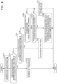
- Fig. 4 is a flowchart illustrating the setting value increase/decrease processing executed by the syringe pump 1.
- the syringe pump 1 acquires position information of the detection target over time using the position acquisition unit 60 (step S101). Specifically, the position acquisition unit 60 acquires the position information of the detection target every predetermined unit time, for example, every 50 milliseconds, and outputs the acquired position information to the control unit 24.
- control unit 24 specifies the operation input by the detection target on the basis of the temporal change in the acquired position information.
- the control unit 24 increases or decreases the setting value on the basis of, for example, a time change in the circumferential direction C (see Fig. 3 ) of the acquired detection region. Specifically, the control unit 24 executes processing of the following steps S102 to S107.
- the control unit 24 determines whether the acquired position information has a temporal change in a first circumferential direction D (see Fig. 3 ), which is one direction of the circumferential direction C (step S102). Specifically, the control unit 24 determines whether the acquired detection region changes with time in the first circumferential direction D between two detection regions adjacent to each other, that is, for example, whether the acquired detection region changes with time from the detection region 61a to the detection region 61b.
- step S102 In a case where it is determined that the acquired position information has a temporal change in the first circumferential direction D (Yes in step S102), the control unit 24 increases the setting value (step S103). On the other hand, in a case where it is determined that the acquired position information does not change with time in the first circumferential direction D (No in step S102), the control unit 24 proceeds to the process of step S104.
- the control unit 24 determines whether the acquired position information has a temporal change in a second circumferential direction E (see Fig. 3 ) that is the other side in the circumferential direction C, that is, the direction opposite to the first circumferential direction D (step S104). Specifically, the control unit 24 determines whether the acquired detection region changes with time in the second circumferential direction E between two detection regions adjacent to each other, that is, for example, whether the acquired detection region changes with time from the detection region 61a to the detection region 61h.
- step S104 In a case where it is determined that the acquired position information has a temporal change in the second circumferential direction E (Yes in step S104), the control unit 24 decreases the setting value (step S105). On the other hand, in a case where it is determined that the acquired position information does not change with time in the second circumferential direction E (No in step S104), the control unit 24 proceeds to the process of step S106.
- the control unit 24 determines whether the acquired position information is constant for a predetermined time or more (step S106).
- the predetermined time used in the process of step S106 is stored in advance in the storage unit 23, and is, for example, 1 second.
- step S107 the control unit 24 determines whether the acquired position information has changed immediately before (step S107). In other words, in the process of step S107, the control unit 24 determines whether the acquired position information up to immediately before the first acquired position information used as the basis of the determination in the process of step S106 has changed. At this time, for example, in a case where there is a period in which the position acquisition unit 60 cannot acquire the position information of the detection target because the detection target is once separated from the operation reception unit 40, the previously acquired position information is reset by second input support processing to be described later. Therefore, in this case, only the position information of the detection target continuously acquired again by the position acquisition unit 60 is the determination target in the process of step S107.
- the control unit 24 increases or decreases the setting value according to the direction in which the acquired position information has changed with time immediately before among the first circumferential direction D and the second circumferential direction E (step S108). Specifically, in a case where the direction in which the acquired position information has changed with time immediately before is the first circumferential direction D, the control unit 24 increases the setting value. On the other hand, in a case where the direction in which the acquired position information has changed with time immediately before is the second circumferential direction E, the control unit 24 decreases the setting value. Thereafter, the control unit 24 continues to increase or decrease the setting value during a period in which the acquired position information is constant.
- the syringe pump 1 increases or decreases the setting value according to the direction in which the acquired position information has changed with time immediately before. Therefore, the operator can continue to increase or decrease the setting value according to the direction in which the detection target has been moved immediately before, without continuing to move the detection target.
- control unit 24 may increase or decrease the setting value by a constant change amount per unit time.
- the operator can estimate the remaining time for the setting value to reach the target value by checking the setting value that changes at a constant rate on the display unit 32, so that the setting value can be easily set to the target value.
- the control unit 24 may increase or decrease the setting value by the change amount per unit time according to the change amount per unit time of the position information that has changed immediately before.
- the control unit 24 may determine the change amount per unit time of the setting value according to the change amount per unit time of the position information that has changed immediately before.
- the control unit 24 may increase the change amount per unit time of the setting value as the change amount per unit time of the position information that has changed immediately before is larger.
- FIG. 4 illustrates an example of the processing of the syringe pump 1 based on the operation performed by the operator using the operation reception unit 40
- the processing of the syringe pump 1 based on the operation performed by the operator using the operation reception unit 40 is not limited to the above-described processing.
- Fig. 5 is an enlarged cross-sectional view illustrating the vicinity of the operation reception unit 40 in the cross-sectional view at the position of the operation reception unit 40 in the syringe pump 1 in an enlarged manner.
- Fig. 6 is an enlarged view illustrating a part of the operation reception surface 40a of the operation reception unit 40.
- Fig. 7 is a diagram illustrating a cross-sectional shape of the operation reception surface 40a of the operation reception unit 40.
- the operation reception surface 40a of the operation reception unit 40 of the present embodiment includes an annular groove 44.
- the annular groove 44 is an endless groove extending in the circumferential direction C.
- the cross-sectional shape of the annular groove 44 of the present embodiment orthogonal to the circumferential direction C which is the extending direction is an arc shape.
- the "arc shape" is not limited to a curve connecting two points on the same circumference, but means a concave curve.
- the operator can perform an operation such as setting value increase/decrease processing (see Fig. 4 ) by moving the fingertip as the detection target along the circumferential direction C on the inner surface of the annular groove 44.
- the operation reception surface 40a includes the above-described annular groove 44
- the fingertip of the operator as the detection target can be arranged so as to be fitted in the annular groove 44, and the fingertip can be easily moved along the annular groove 44.
- the cross-sectional shape of the annular groove 44 into the arc shape, the inner surface of the annular groove 44 easily comes into contact with the ball of the finger in a wide range along the ball of the finger of the operator as compared with the case where the cross-sectional shape is a rectangular shape. That is, the fingertip is easily positioned in the annular groove 44.
- an uneven surface 200 see Figs. 6 and 7
- the operation reception surface 40a is formed on at least a part of the inner surface of the annular groove 44.
- the operation reception surface 40a of the present embodiment includes a central protruding portion 42, a peripheral wall 43, and an annular groove 44.
- the central protruding portion 42 protrudes at a position corresponding to the central portion 41.
- the peripheral wall 43 is separated radially outward from the central protruding portion 42 and protrudes so as to surround the central protruding portion 42.
- the peripheral wall 43 extends along the circumferential direction C around the central protruding portion 42.
- the annular groove 44 is located between the central protruding portion 42 and the peripheral wall 43.
- the edge of the peripheral wall 43 protrudes outward from the outer surface of the housing 46, but the present invention is not limited to this configuration.
- the edge of the peripheral wall 43 may be flush with the outer surface of the housing 46.
- the operation reception unit 40 is preferably an integrally molded product with the housing 46 from the viewpoint of suppressing deterioration in operability and improving cleaning performance.
- the position acquisition unit 60 does not detect the position information of the detection target in the vicinity of the central portion 41 by the central protruding portion 42. Therefore, the position acquisition unit 60 can suppress simultaneous acquisition of a plurality of detection regions not adjacent in the circumferential direction C as acquired detection regions.
- the housing 46 is an exterior member of the syringe pump 1 that accommodates the position acquisition unit 60, the control unit 24, and the like.
- the outer surface of the housing 46 of the present embodiment includes an inclined surface portion 46a.
- the inclined surface portion 46a is a surface extending so as to be inclined with respect to the horizontal direction so as to face upward in the vertical direction in the use state of the syringe pump 1.
- the use state of the syringe pump 1 means, for example, a state in which the syringe pump 1 is in a usable posture, such as a state in which the syringe pump 1 is fixed to a stand.
- the posture of the syringe pump 1 in which the upper side in the direction B orthogonal to the extending direction A is the upper side in the vertical direction is the use state of the syringe pump 1.
- the operation reception surface 40a of the operation reception unit 40 is exposed from the inclined surface portion 46a of the housing 46 and extends along the inclined surface portion 46a. In this way, the operator can easily operate the operation reception surface 40a from the upper side in the vertical direction, and the operability of the operation reception surface 40a by the operator can be improved.
- the operation reception surface 40a includes an uneven surface 200 having a sea-island structure in which a plurality of protruding surface portions 201 are dispersedly arranged per 1 mm square area.
- the phrase "the plurality of protruding surface portions 201 are dispersedly arranged per 1 mm square area" as used herein means that at least a part of each of at least two or more protruding surface portions 201 is dispersedly arranged per 1 mm square area. That is, at least two or more protruding surface portions 201 may not be entirely included per 1 mm square area.
- the uneven surface 200 of the present embodiment is formed on the inner surface of the annular groove 44. More specifically, the uneven surface 200 of the present embodiment is formed over the entire recessed surface integrally forming the groove wall surface and the bottom surface of the annular groove 44. As illustrated in Figs. 6 and 7 , the uneven surface 200 includes a plurality of protruding surface portions 201 formed in independent protrusions, and a recessed surface portion 202 continuous around the plurality of protruding surface portions 201. In other words, the recessed surface portion 202 forms a continuous reference surface L.
- an uneven surface in which a plurality of hole-shaped independent recessed surface portions are formed with respect to a protruding surface portion as a continuous reference surface may be referred to as a "satin-like surface”.
- the above-described concavo-convex relationship of the uneven surface 200 is opposite to the concavo-convex relationship of the satin-like surface.
- the uneven surface 200 is a surface similar to a surface formed by transferring the satin-like surface. Therefore, hereinafter, for convenience of description, the uneven surface 200 of the present embodiment may be referred to as a "transferred satin-like surface", but the method for forming the uneven surface 200 is not limited to transfer of the satin-like surface.
- the operation reception surface 40a includes the uneven surface 200 having the sea-island structure described above, it is possible to achieve both improvement in operability in a state where a glove is worn and suppression of decrease in detection accuracy of an operation in a state where liquid is attached.
- examples of the material of the glove used in the medical field include polyvinyl chloride, polyethylene, nitrile, and natural rubber latex. Since the operation reception surface 40a includes the uneven surface 200 having the sea-island structure described above, the contact area with the fingertip of the operator as the detection target can be reduced as compared with a configuration in which the operation reception surface 40a includes only a smooth surface without including the uneven surface 200. Therefore, even when the operator wears the above-described resin or rubber glove, the contact area with the glove can be reduced, and the sliding resistance between the operation reception surface 40a and the glove can be reduced. This improves operability in a state where the glove is worn.
- the uneven surface 200 is a transfer satin-like surface, and has a sea-island structure in which a plurality of protruding surface portions 201 are dispersedly arranged per 1 mm square area. Therefore, the droplets of the liquid such as the medicinal solution adhering to the top of the protruding surface portion 201 are discretely dispersed on the uneven surface 200. Thus, the droplets can be prevented from coalescing and spreading on the uneven surface 200. As a result, the liquid adhering to the uneven surface 200 becomes an unintended conductive path, and it is possible to prevent the position acquisition unit 60 from erroneously detecting the position information of the detection target.
- the shortest distance between the apexes of the adjacent protruding surface portions 201 on the uneven surface 200 may be, for example, 50 ⁇ m to 500 ⁇ m.
- the material for forming the uneven surface 200 include polycarbonate, PC-ABS, ABS resin, and ASA resin.
- the area ratio of the protruding surface portion 201 at a cross-sectional position of a height of 50% or more of the uneven surface 200 per 300 ⁇ m square area of the uneven surface 200 (hereinafter, for convenience of description, simply referred to as "an area ratio of 50% or more of the protruding surface portion 201”) is preferably more than 0% and 60% or less.
- "height of 50%” means a position of 50% in a height direction F when the lowest position in the height direction F orthogonal to the uneven surface 200 is 0% and the highest position is 100%. Therefore, the "height of 50% or more” means any position from the 50% position to the 100% position described above.
- the above-described height direction F means a normal direction at a center point in a 300 ⁇ m square region of the uneven surface 200.
- the "cross-sectional position at a height of 50% or more of the uneven surface 200” means a cross-sectional position orthogonal to the height direction F at an arbitrary position at a height of 50% or more of the uneven surface 200.
- the protruding surface portion 201 at the position of 50% to 100% of the height of the uneven surface 200 can be appropriately dispersed to such an extent that the droplets adhering to the top of the protruding surface portion 201 do not coalesce.
- the protruding surface portion 201 at the position of 50% to 100% of the height of the uneven surface 200 can be appropriately dispersed to such an extent that the droplets adhering to the top of the protruding surface portion 201 do not coalesce.
- even in a state where liquid adheres to the operation reception surface 40a it is possible to further suppress a decrease in detection accuracy of the operation of the operation reception surface 40a by the operator.
- the area ratio of 50% or more of the protruding surface portion 201 is more than 0%, more preferably 40% or less, and still more preferably 20% or less.
- the area ratio of the protruding surface portion 201 at a cross-sectional position of a height of 70% or more of the uneven surface 200 per 300 ⁇ m square area of the uneven surface 200 (hereinafter, for convenience of description, simply referred to as "an area ratio of 70% or more of the protruding surface portion 201") is preferably more than 0% and 20% or less. In this way, even in a state where liquid adheres to the operation reception surface 40a, it is possible to further suppress a decrease in detection accuracy of the operation of the operation reception surface 40a by the operator.
- the area ratio of 70% or more of the protruding surface portion 201 is more than 0%, more preferably 15% or less, and still more preferably 5% or less.
- the area ratio of 50% or more of the protruding surface portion 201 is more than 0% and 60% or less, and the area ratio of 70% or more of the protruding surface portion 201 is more than 0% and 20% or less. In this way, even in a state where liquid adheres to the operation reception surface 40a, it is possible to further suppress a decrease in detection accuracy of the operation of the operation reception surface 40a by the operator.
- the area ratio of 50% or more and the area ratio of 70% or more of the protruding surface portion 201 described above can be obtained by measuring the area ratio after setting the objective lens to 20 times, the laser brightness to 50%, and the scan pitch to 0.2 ⁇ m, and analyzing the threshold setting as a histogram in the area measurement using a 3D measurement laser microscope (Olympus Corporation, 3D MEASURING LASER MICROSCOPE OLS4000).
- the area ratio of 50% or more of the protruding surface portion as a continuous reference surface is 80% or more.
- the area ratio of 70% or more of the protruding surface portion as a continuous reference surface is 25% or more.
- the height 0 to 100% in the case of the satin-like surface is set such that the lowest position among the plurality of recesses in the independent state is 0% and the highest position among the protruding surface portions as the continuous reference surface is 100% per area of 300 ⁇ m square.
- the area ratio of 50% or more of the protruding surface portion of the satin-like surface is larger than the area ratio of 50% or more of the protruding surface portion 201 of the uneven surface 200 described above.
- the area ratio of 70% or more of the protruding surface portion of the satin-like surface is also larger than the area ratio of 70% or more of the protruding surface portion 201 of the uneven surface 200 described above. Therefore, in the case of the satin-like surface, the droplets easily coalesce and spread on the protruding surface portion as the continuous reference surface as compared with the above-described uneven surface 200. As a result, the attached liquid tends to form an unintended conductive path. That is, in a case where the operation reception surface is formed of a satin-like surface, if liquid adheres, position information of a detection target is likely to be erroneously detected.
- An arithmetic average height Sa ( ⁇ m) of the uneven surface 200 is preferably 0.82 to 1.44 ⁇ m.
- the arithmetic average height Sa ( ⁇ m) is a value measured in accordance with ISO 25178 and JIS B0681. Specifically, the measured value can be obtained by using a device such as a 3D measuring laser microscope (Olympus Corporation, 3D MEASURING LASER MICROSCOPE OLS4000) similar to the above, under the measurement conditions as described above, or under the measurement conditions and the measurement method conforming to the standards.
- the medical device according to the present disclosure is not limited to the specific configurations illustrated in the above-described embodiments, and various changes and modifications can be made without departing from the scope of the claims.
- the medical device according to the present disclosure is not limited to the syringe pump shown in the above-described embodiment, and may be, for example, a liquid feeding pump such as an infusion pump, a nutrient pump, or an insulin pump.
- the present disclosure relates to a medical device.
Landscapes
- Health & Medical Sciences (AREA)
- Engineering & Computer Science (AREA)
- Life Sciences & Earth Sciences (AREA)
- General Engineering & Computer Science (AREA)
- Veterinary Medicine (AREA)
- Theoretical Computer Science (AREA)
- Public Health (AREA)
- Vascular Medicine (AREA)
- Anesthesiology (AREA)
- Biomedical Technology (AREA)
- Heart & Thoracic Surgery (AREA)
- Hematology (AREA)
- General Health & Medical Sciences (AREA)
- Animal Behavior & Ethology (AREA)
- Physics & Mathematics (AREA)
- Human Computer Interaction (AREA)
- General Physics & Mathematics (AREA)
- Infusion, Injection, And Reservoir Apparatuses (AREA)
Abstract
Description
- The present disclosure relates to a medical device.
- There is known a medical device that includes an input device that receives an input operation by an operator, sets a setting value on the basis of the received input operation, and operates on the basis of the setting value. Examples of such a medical device include a syringe pump in which a syringe containing a liquid such as a medicinal solution is placed, and a speed at which a pusher of the placed syringe is pushed out is controlled according to a setting value set by an operator to feed the liquid into a living body such as a patient while controlling a flow rate. A medical device such as a syringe pump includes a touch panel as an input device used for setting a predetermined setting value such as an administration rate, and can change the setting value on the basis of a touch operation performed on the touch panel (see, for example, Patent Literature 1).
- Patent Literature 1:
JP 6736981 B1 - At a medical site, an operator may operate a panel surface as an operation reception surface of a touch panel as an operation reception unit of a medical device in a state of wearing a glove instead of a bare hand. Therefore, the operation reception surface of the medical device is preferably configured to be easily operated not only with bare hands but also in a state of wearing a glove.
- In addition, a liquid such as a medicinal solution may adhere to the operation reception surface. In a state where the liquid adhering to the operation reception surface is retained, detection accuracy of the operation of the operation reception surface by the operator may be deteriorated by the retained liquid.
- An object of the present disclosure is to provide a medical device including an operation reception surface capable of achieving both improvement in operability in a state where a glove is worn and suppression of decrease in detection accuracy of an operation in a state where liquid is attached.
- A medical device as a first aspect of the present disclosure includes:
- (1) an operation reception unit that includes an operation reception surface;
- a position acquisition unit that is capable of acquiring position information based on a position of a detection target on the operation reception surface, the detection target being in contact with or in proximity to the operation reception surface of the operation reception unit; and
- a control unit that specifies an operation input by the detection target on a basis of a change in the acquired position information, in which
- the operation reception surface includes an uneven surface having a sea-island structure in which a plurality of protruding surface portions are dispersedly arranged per 1 mm square area.
- In the medical device according to (1) as one embodiment of the present disclosure,
- (2) the position acquisition unit is a capacitive position detection sensor capable of acquiring the position information of the detection target by detecting a change in capacitance caused by contact or proximity of the detection target to the operation reception surface.
In the medical device according to (1) or (2) as one embodiment of the present disclosure, - (3) an area ratio of the protruding surface portion at a cross-sectional position of a height of 50% or more of the uneven surface per area of a 300 µm square of the uneven surface is more than 0% and 60% or less, and
- the height of 50% or more means a position of 50% or more in a height direction in a case where a lowest position is 0% and a highest position is 100% in the height direction orthogonal to the uneven surface.
- In the medical device according to any one of (1) to (3) as one embodiment of the present disclosure,
- (4) an area ratio of the protruding surface portion at a cross-sectional position of a height of 70% or more of the uneven surface per area of a 300 µm square of the uneven surface is more than 0% and 20% or less, and
- the height of 70% or more means a position of 70% or more in a height direction in a case where a lowest position is 0% and a highest position is 100% in the height direction orthogonal to the uneven surface.
- In the medical device according to any one of (1) to (4) as one embodiment of the present disclosure,
- (5) an arithmetic average height of the uneven surface is 0.82 to 1.44 µm.
The medical device according to any one of (1) to (5) as one embodiment of the present disclosure includes: - (6) a housing that accommodates the position acquisition unit and the control unit, in which
- an outer surface of the housing includes an inclined surface portion extending obliquely with respect to a horizontal direction so as to face an upper side in a vertical direction in a use state, and
- the operation reception surface of the operation reception unit is exposed from the inclined surface portion of the housing and extends along the inclined surface portion.
- In the medical device according to any one of (1) to (6) as one embodiment of the present disclosure,
- (7) the operation reception surface includes an annular groove having an arcuate cross-sectional shape orthogonal to an extending direction, and
the uneven surface is formed on an inner surface of the annular groove. - According to the present disclosure, it is possible to provide a medical device including an operation reception surface capable of achieving both improvement in operability in a state where a glove is worn and suppression of decrease in detection accuracy of an operation in a state where liquid is attached.
-
-
Fig. 1 is a perspective view of a syringe pump as an embodiment of a medical device according to the present disclosure. -
Fig. 2 is a block diagram illustrating a configuration of a syringe pump illustrated inFig. 1 . -
Fig. 3 is a diagram illustrating an example of arrangement of detection regions on an operation reception surface of the syringe pump illustrated inFig. 1 . -
Fig. 4 is a flowchart illustrating setting value increase/decrease processing executed by the syringe pump illustrated inFig. 1 . -
Fig. 5 is an enlarged cross-sectional view illustrating the vicinity of an operation reception unit in a cross-sectional view at a position of the operation reception unit in the syringe pump illustrated inFig. 1 in an enlarged manner. -
Fig. 6 is an enlarged view illustrating a part of the operation reception surface of the operation reception unit. -
Fig. 7 is a diagram illustrating a cross-sectional shape of the operation reception surface of the operation reception unit. -
Fig. 8 illustrates an experimental result of an experiment for evaluating the influence of the glove operability and the liquid discreteness depending on the arithmetic average height of the uneven surface of the operation reception surface. - Hereinafter, embodiments of a medical device according to the present disclosure will be described by way of example with reference to the drawings. In the drawings, the same components are denoted by the same reference numerals.
-
Fig. 1 is a perspective view of asyringe pump 1 as an embodiment of a medical device according to the present disclosure.Fig. 1 illustrates thesyringe pump 1 with asyringe 50 placed thereon. As illustrated inFig. 1 , thesyringe pump 1 is configured as a pump for feeding a liquid stored in ahollow portion 52 of thesyringe 50.Fig. 2 is a block diagram illustrating a configuration of thesyringe pump 1. In the present embodiment, thesyringe pump 1 as a medical device will be described as an example, but the medical device according to the present disclosure is not limited to the syringe pump. - As illustrated in
Figs. 1 and2 , thesyringe pump 1 includes aplacement portion 11, aslider 12, aclamp 14, acylinder flange holder 15, acircuit unit 20, aninput button group 31, adisplay unit 32, aslider drive unit 36, anoperation reception unit 40, ahousing 46, and aposition acquisition unit 60. - As illustrated in
Fig. 1 , thesyringe 50 can be placed on theplacement portion 11. Thesyringe 50 placed on theplacement portion 11 includes acylindrical cylinder 51 that defines thehollow portion 52 therein, and apusher 55 that is inserted into thehollow portion 52 from the proximal end side of thecylinder 51 and is movable in thehollow portion 52 along an extending direction A of the cylinder 51 (hereinafter, it is simply referred to as an "extending direction A") while being in close contact with the inner peripheral surface of thecylinder 51 in the circumferential direction without any gap. Thecylinder 51 has acylinder flange 53 at a proximal end, and defines anoutlet hole 54 that communicates thehollow portion 52 with the outside at a distal end. A flexible tube can be connected to the distal end of thecylinder 51. When the tube is connected to the distal end of thecylinder 51, theoutlet hole 54 communicates with the flow path in the tube. Thehollow portion 52 of thesyringe 50 contains a liquid such as a medicinal solution. Hereinafter, in the extending direction A, a direction from the proximal end side to the distal end side of thecylinder 51 may be referred to as "distal end side in the extending direction A", and a direction from the distal end side to the proximal end side of thecylinder 51 may be referred to as "proximal end side in the extending direction A". - As illustrated in
Fig. 1 , thecylinder 51 of thesyringe 50 can be placed on theplacement portion 11. As illustrated inFig. 1 , thecylinder flange holder 15 houses a part of thecylinder flange 53 when thecylinder 51 of thesyringe 50 is placed on theplacement portion 11. As a result, the position of thecylinder 51 with respect to thesyringe pump 1 is fixed. - As illustrated in
Fig. 1 , theslider 12 includes apusher fixing portion 13. Theslider 12 is movable to engage with thepusher 55 of thesyringe 50 placed on theplacement portion 11. Specifically, theslider 12 is movable along the extending direction A at a position on the proximal end side in the extending direction A with respect to thepusher 55 of thesyringe 50 placed on theplacement portion 11. Theslider 12 fixes thepusher 55 of thesyringe 50 placed on theplacement portion 11 by thepusher fixing portion 13. In a state where thepusher 55 is fixed to theslider 12 by thepusher fixing portion 13, thepusher 55 moves integrally with theslider 12 along with the movement of theslider 12 in the extending direction A. At this time, thecylinder 51 placed on theplacement portion 11 is fixed in the extending direction A with respect to thesyringe pump 1 by thecylinder flange holder 15. Therefore, when theslider 12 moves to the distal end side of thesyringe 50, thepusher 55 moves to the distal end side with respect to thecylinder 51, and the liquid stored in thehollow portion 52 is discharged from theoutlet hole 54. Therefore, the liquid stored in thehollow portion 52 can be fed into the living body through a flow path defined by a tube connectable to the distal end of thecylinder 51. - As illustrated in
Fig. 1 , theclamp 14 is movable along a direction B orthogonal to the extending direction A, and can fix thecylinder 51 of the placedsyringe 50 so as to be sandwiched between theplacement portion 11 and the clamp. By fixing thecylinder 51 with theclamp 14, a part of thecylinder flange 53 is hardly detached from thecylinder flange holder 15, so that thecylinder 51 is firmly fixed to thesyringe pump 1. - As illustrated in
Fig. 2 , thecircuit unit 20 includes acommunication unit 21, aclocking unit 22, astorage unit 23, and acontrol unit 24. - The
communication unit 21 includes a communication interface that transmits and receives information to and from an information processing device such as an external computer by wireless communication or wired communication. The communication interface is, for example, an interface compatible with a mobile communication standard such as LTE, 4G standard, or 5G standard, an interface compatible with short-range wireless communication such as Bluetooth (registered trademark), an interface compatible with a wireless LAN communication standard such as IEEE 802.11, or an interface compatible with a wired LAN communication standard such as Ethernet (registered trademark). The "LTE" is an abbreviation for long term evolution. The "4G" is an abbreviation for 4th generation. The "5G" is an abbreviation for 5th generation. "IEEE" is an abbreviation for Institute of Electrical and Electronics Engineers. - The clocking
unit 22 measures time and clocks time. The clockingunit 22 may be realized by, for example, a real time clock (RTC). The clockingunit 22 may be realized as one function of thecontrol unit 24. - The
storage unit 23 includes, for example, a storage device, and stores various types of information and programs. Specifically, thestorage unit 23 stores a program for executing setting value increase/decrease processing executed by thecontrol unit 24, various types of input support processing, and the like. Thestorage unit 23 stores information of a predetermined setting value (hereinafter, it is simply referred to as a "setting value".) such as the flow rate and the dose of the liquid fed by thesyringe pump 1, a control program for driving theslider drive unit 36 based on the setting value and feeding the liquid, and the like. Thestorage unit 23 stores one of a first circumferential direction and a second circumferential direction as a temporary storage direction. Details of the temporary storage direction stored in thestorage unit 23 will be described later. Thestorage unit 23 includes at least one semiconductor memory, at least one magnetic memory, at least one optical memory, or any combination thereof. The semiconductor memory is, for example, a RAM, a ROM, or a flash memory. The "RAM" is an abbreviation for a random access memory. "ROM" is an abbreviation for read only memory. The RAM is, for example, an SRAM or a DRAM. "SRAM" is an abbreviation for static random access memory. "DRAM" is an abbreviation for dynamic random access memory. The ROM is, for example, an EEPROM. The "EEPROM" is an abbreviation for an electrically erasable programmable read only memory. The flash memory is, for example, an SSD. The "SSD" is an abbreviation for a solid-state drive. The magnetic memory is, for example, an HDD. The "HDD" is an abbreviation for a hard disk drive. - The
control unit 24 includes, for example, at least one processor, at least one programmable circuit, at least one dedicated circuit, or an arbitrary combination thereof that implements a predetermined function by reading predetermined information and a program among various information and programs stored in thestorage unit 23. Then, thecontrol unit 24 controls the operation of theentire syringe pump 1. The processor is a general-purpose processor such as a CPU or GPU, or a dedicated processor specialized for specific processing. "CPU" is an abbreviation for central processing unit. "GPU" is an abbreviation for graphics processing unit. The programmable circuit is, for example, an FPGA. "FPGA" is an abbreviation for field-programmable gate array. The dedicated circuit is, for example, an ASIC. The "ASIC" is an abbreviation for an application specific integrated circuit. As will be described later, thecontrol unit 24 specifies an operation input from anoperation reception surface 40a of theoperation reception unit 40 by a detection target such as the operator's fingertip. Specifically, thecontrol unit 24 reads predetermined information and a program stored in thestorage unit 23, and executes processing such as setting value increase/decrease processing and various types of input support processing. Thecontrol unit 24 transmits and receives information to and from an external information processing device via thecommunication unit 21. Thecontrol unit 24 executes various types of processing on the basis of the information input from theinput button group 31 and theposition acquisition unit 60, and outputs information accompanying the execution of the various types of processing from thedisplay unit 32. - As illustrated in
Fig. 1 , theinput button group 31 includes various operation buttons disposed on the surface of thehousing 46 and capable of receiving an input operation by an operator. Theinput button group 31 includes, for example, a power button for switching on/off of the operation power of thesyringe pump 1, a start button for starting liquid feeding, and a stop button for stopping liquid feeding. Theinput button group 31 outputs the input information to thecontrol unit 24. - As illustrated in
Fig. 1 , thedisplay unit 32 includes, for example, a display device such as a liquid crystal display or an organic EL display. Thedisplay unit 32 displays a setting value and an actual measurement value of the flow rate of the liquid to be fed, a setting value and an actual measurement value of the dose of the liquid to be fed, various alarm information, and the like on the basis of a signal from thecontrol unit 24. - The
slider drive unit 36 includes, for example, a motor, and moves theslider 12 along the extending direction A (seeFig. 1 ) based on a signal from thecontrol unit 24. - As illustrated in
Fig. 1 , theoperation reception unit 40 is disposed so as to be at least partially exposed to the outside of thesyringe pump 1. More specifically, theoperation reception unit 40 includes theoperation reception surface 40a exposed from thehousing 46. Details of theoperation reception unit 40 will be described later. - The
position acquisition unit 60 can acquire position information based on the position on theoperation reception surface 40a of the detection target such as the fingertip of the operator in contact with or in proximity to theoperation reception surface 40a of theoperation reception unit 40. Theposition acquisition unit 60 acquires position information over time. Specifically, theposition acquisition unit 60 acquires the position information at a predetermined acquisition timing. The predetermined acquisition timing occurs, for example, at a predetermined cycle. The predetermined acquisition timing may occur, for example, every 10 milliseconds. In this case, theposition acquisition unit 60 acquires the position information every 10 milliseconds. However, the predetermined cycle is not limited to 10 milliseconds. The predetermined cycle may be appropriately determined according to the use, specification, or the like of theoperation reception unit 40. However, theposition acquisition unit 60 preferably acquires the position information every 5 milliseconds to 100 milliseconds, and more preferably acquires the position information every 5 milliseconds to 50 milliseconds. By setting the time interval at which theposition acquisition unit 60 acquires the position information to be equal to or less than the upper limit of the above range, for example, in a case where the position of the detection target is quickly changed, it is possible to reduce the possibility that thecontrol unit 24 erroneously recognizes that the direction in which the detection target has actually rotated has rotated in the opposite direction. Theposition acquisition unit 60 outputs the acquired position information to thecontrol unit 24. - The
position acquisition unit 60 of the present embodiment is a capacitive position detection sensor capable of acquiring position information of the detection target by detecting a change in capacitance caused by contact or proximity of the detection target to theoperation reception surface 40a. For example, theposition acquisition unit 60 may include a plurality of electrodes corresponding to a plurality of detection regions on theoperation reception surface 40a, and may acquire position information of the detection target on theoperation reception surface 40a based on a change in capacitance between the detection target and each electrode in a case where the detection target of the operator comes into contact with theoperation reception surface 40a. -
Fig. 3 is a diagram illustrating an example of the arrangement of the detection regions on theoperation reception surface 40a. As illustrated inFig. 3 , theposition acquisition unit 60 of the present embodiment can detect a plurality of detection regions, for example, eight fan-shapeddetection regions 61a to 61h, arranged without a gap along a circumferential direction C around acentral portion 41 on theoperation reception surface 40a. - The
position acquisition unit 60 acquires, as the position information of the detection target, the detection region that the detection target touches or comes closest to among the plurality ofdetection regions 61a to 61h. Specifically, for example, theposition acquisition unit 60 may acquire information indicating the position of the detection target in the three-dimensional space, and acquire a detection region where the position is closest as the position information of the detection target. In addition, theposition acquisition unit 60 may be configured with, for example, a detection unit such as a touch pad capable of detecting contact of the detection target in each of a plurality of detection regions, and acquire the detection region in which the contact has been detected as the position information of the detection target. Theposition acquisition unit 60 outputs information of the detection region as the acquired position information to thecontrol unit 24. Hereinafter, the position information of the detection target acquired by theposition acquisition unit 60 will be referred to as "acquired position information", and the detection region acquired as the position information of the detection target by theposition acquisition unit 60 will be referred to as "acquired detection region". - As described above, the
syringe pump 1 as the medical device of the present embodiment includes theoperation reception unit 40 including theoperation reception surface 40a, theposition acquisition unit 60 capable of acquiring the position information based on the position on theoperation reception surface 40a of the detection target in contact with or in proximity to theoperation reception unit 40, and thecontrol unit 24 that specifies the operation input by the detection target on the basis of the change in the position information acquired by theposition acquisition unit 60. As a result, since thesyringe pump 1 does not need to be provided with a rotating member that physically rotates as an input device, it is possible to suppress deterioration of operability even if foreign matter such as liquid adheres. Furthermore, since it is not necessary to provide a rotating member, thesyringe pump 1 can have a configuration with a small gap. Therefore, cleaning performance can be improved. - Next, an example of processing of the
syringe pump 1 will be described with reference toFig. 4. Fig. 4 is a flowchart illustrating the setting value increase/decrease processing executed by thesyringe pump 1. As illustrated inFig. 4 , first, thesyringe pump 1 acquires position information of the detection target over time using the position acquisition unit 60 (step S101). Specifically, theposition acquisition unit 60 acquires the position information of the detection target every predetermined unit time, for example, every 50 milliseconds, and outputs the acquired position information to thecontrol unit 24. - Thereafter, the
control unit 24 specifies the operation input by the detection target on the basis of the temporal change in the acquired position information. Thecontrol unit 24 increases or decreases the setting value on the basis of, for example, a time change in the circumferential direction C (seeFig. 3 ) of the acquired detection region. Specifically, thecontrol unit 24 executes processing of the following steps S102 to S107. - The
control unit 24 determines whether the acquired position information has a temporal change in a first circumferential direction D (seeFig. 3 ), which is one direction of the circumferential direction C (step S102). Specifically, thecontrol unit 24 determines whether the acquired detection region changes with time in the first circumferential direction D between two detection regions adjacent to each other, that is, for example, whether the acquired detection region changes with time from thedetection region 61a to thedetection region 61b. - In a case where it is determined that the acquired position information has a temporal change in the first circumferential direction D (Yes in step S102), the
control unit 24 increases the setting value (step S103). On the other hand, in a case where it is determined that the acquired position information does not change with time in the first circumferential direction D (No in step S102), thecontrol unit 24 proceeds to the process of step S104. - The
control unit 24 determines whether the acquired position information has a temporal change in a second circumferential direction E (seeFig. 3 ) that is the other side in the circumferential direction C, that is, the direction opposite to the first circumferential direction D (step S104). Specifically, thecontrol unit 24 determines whether the acquired detection region changes with time in the second circumferential direction E between two detection regions adjacent to each other, that is, for example, whether the acquired detection region changes with time from thedetection region 61a to thedetection region 61h. - In a case where it is determined that the acquired position information has a temporal change in the second circumferential direction E (Yes in step S104), the
control unit 24 decreases the setting value (step S105). On the other hand, in a case where it is determined that the acquired position information does not change with time in the second circumferential direction E (No in step S104), thecontrol unit 24 proceeds to the process of step S106. - The
control unit 24 determines whether the acquired position information is constant for a predetermined time or more (step S106). The predetermined time used in the process of step S106 is stored in advance in thestorage unit 23, and is, for example, 1 second. - In a case where it is determined that the acquired position information is constant for the predetermined time or more (Yes in step S106), the
control unit 24 determines whether the acquired position information has changed immediately before (step S107). In other words, in the process of step S107, thecontrol unit 24 determines whether the acquired position information up to immediately before the first acquired position information used as the basis of the determination in the process of step S106 has changed. At this time, for example, in a case where there is a period in which theposition acquisition unit 60 cannot acquire the position information of the detection target because the detection target is once separated from theoperation reception unit 40, the previously acquired position information is reset by second input support processing to be described later. Therefore, in this case, only the position information of the detection target continuously acquired again by theposition acquisition unit 60 is the determination target in the process of step S107. - In a case where it is determined that the acquired position information has changed immediately before (Yes in step S107), the
control unit 24 increases or decreases the setting value according to the direction in which the acquired position information has changed with time immediately before among the first circumferential direction D and the second circumferential direction E (step S108). Specifically, in a case where the direction in which the acquired position information has changed with time immediately before is the first circumferential direction D, thecontrol unit 24 increases the setting value. On the other hand, in a case where the direction in which the acquired position information has changed with time immediately before is the second circumferential direction E, thecontrol unit 24 decreases the setting value. Thereafter, thecontrol unit 24 continues to increase or decrease the setting value during a period in which the acquired position information is constant. - In a case where it is determined that the acquired position information is not constant for the predetermined time or more (No in step S106), or in a case where it is determined that the acquired position information has not changed immediately before (No in step S107), the
control unit 24 does not change the setting value (step S109). - As described above, in a case where the acquired position information is constant for a predetermined time or more and the acquired position information has changed immediately before, the
syringe pump 1 increases or decreases the setting value according to the direction in which the acquired position information has changed with time immediately before. Therefore, the operator can continue to increase or decrease the setting value according to the direction in which the detection target has been moved immediately before, without continuing to move the detection target. - In the process of step S108, the
control unit 24 may increase or decrease the setting value by a constant change amount per unit time. As a result, the operator can estimate the remaining time for the setting value to reach the target value by checking the setting value that changes at a constant rate on thedisplay unit 32, so that the setting value can be easily set to the target value. - In the process of step S108, the
control unit 24 may increase or decrease the setting value by the change amount per unit time according to the change amount per unit time of the position information that has changed immediately before. In other words, thecontrol unit 24 may determine the change amount per unit time of the setting value according to the change amount per unit time of the position information that has changed immediately before. Specifically, thecontrol unit 24 may increase the change amount per unit time of the setting value as the change amount per unit time of the position information that has changed immediately before is larger. As described above, since thesyringe pump 1 determines the change rate of the setting value according to the change speed of the position information that has changed immediately before, thesyringe pump 1 can change the setting value at a rate corresponding to the operation immediately before the operator. - Although
Fig. 4 illustrates an example of the processing of thesyringe pump 1 based on the operation performed by the operator using theoperation reception unit 40, the processing of thesyringe pump 1 based on the operation performed by the operator using theoperation reception unit 40 is not limited to the above-described processing. - Next, the
operation reception surface 40a of theoperation reception unit 40 will be described in detail with reference toFigs. 1 ,3 , and5 to 7 .Fig. 5 is an enlarged cross-sectional view illustrating the vicinity of theoperation reception unit 40 in the cross-sectional view at the position of theoperation reception unit 40 in thesyringe pump 1 in an enlarged manner.Fig. 6 is an enlarged view illustrating a part of theoperation reception surface 40a of theoperation reception unit 40.Fig. 7 is a diagram illustrating a cross-sectional shape of theoperation reception surface 40a of theoperation reception unit 40. - As illustrated in
Figs. 1 ,3 , and5 , theoperation reception surface 40a of theoperation reception unit 40 of the present embodiment includes anannular groove 44. Theannular groove 44 is an endless groove extending in the circumferential direction C. In addition, the cross-sectional shape of theannular groove 44 of the present embodiment orthogonal to the circumferential direction C which is the extending direction is an arc shape. Here, the "arc shape" is not limited to a curve connecting two points on the same circumference, but means a concave curve. The operator can perform an operation such as setting value increase/decrease processing (seeFig. 4 ) by moving the fingertip as the detection target along the circumferential direction C on the inner surface of theannular groove 44. Since theoperation reception surface 40a includes the above-describedannular groove 44, the fingertip of the operator as the detection target can be arranged so as to be fitted in theannular groove 44, and the fingertip can be easily moved along theannular groove 44. In addition, by forming the cross-sectional shape of theannular groove 44 into the arc shape, the inner surface of theannular groove 44 easily comes into contact with the ball of the finger in a wide range along the ball of the finger of the operator as compared with the case where the cross-sectional shape is a rectangular shape. That is, the fingertip is easily positioned in theannular groove 44. In this manner, since theoperation reception surface 40a includes the above-describedannular groove 44, operability of theoperation reception surface 40a can be enhanced. Although details will be described later, an uneven surface 200 (seeFigs. 6 and7 ) of theoperation reception surface 40a is formed on at least a part of the inner surface of theannular groove 44. - More specifically, the
operation reception surface 40a of the present embodiment includes a central protrudingportion 42, aperipheral wall 43, and anannular groove 44. The central protrudingportion 42 protrudes at a position corresponding to thecentral portion 41. Theperipheral wall 43 is separated radially outward from the central protrudingportion 42 and protrudes so as to surround the central protrudingportion 42. Theperipheral wall 43 extends along the circumferential direction C around the central protrudingportion 42. Theannular groove 44 is located between the central protrudingportion 42 and theperipheral wall 43. In the present embodiment, the edge of theperipheral wall 43 protrudes outward from the outer surface of thehousing 46, but the present invention is not limited to this configuration. The edge of theperipheral wall 43 may be flush with the outer surface of thehousing 46. Theoperation reception unit 40 is preferably an integrally molded product with thehousing 46 from the viewpoint of suppressing deterioration in operability and improving cleaning performance. - The
position acquisition unit 60 does not detect the position information of the detection target in the vicinity of thecentral portion 41 by the central protrudingportion 42. Therefore, theposition acquisition unit 60 can suppress simultaneous acquisition of a plurality of detection regions not adjacent in the circumferential direction C as acquired detection regions. - As illustrated in
Fig. 1 , thehousing 46 is an exterior member of thesyringe pump 1 that accommodates theposition acquisition unit 60, thecontrol unit 24, and the like. As illustrated inFig. 1 , the outer surface of thehousing 46 of the present embodiment includes aninclined surface portion 46a. Theinclined surface portion 46a is a surface extending so as to be inclined with respect to the horizontal direction so as to face upward in the vertical direction in the use state of thesyringe pump 1. The use state of thesyringe pump 1 means, for example, a state in which thesyringe pump 1 is in a usable posture, such as a state in which thesyringe pump 1 is fixed to a stand. InFig. 1 , the posture of thesyringe pump 1 in which the upper side in the direction B orthogonal to the extending direction A is the upper side in the vertical direction is the use state of thesyringe pump 1. As illustrated inFigs. 1 and5 , theoperation reception surface 40a of theoperation reception unit 40 is exposed from theinclined surface portion 46a of thehousing 46 and extends along theinclined surface portion 46a. In this way, the operator can easily operate theoperation reception surface 40a from the upper side in the vertical direction, and the operability of theoperation reception surface 40a by the operator can be improved. - Next, details of the
operation reception surface 40a will be described with reference toFigs. 6 and7 . As illustrated inFigs. 6 and7 , theoperation reception surface 40a includes anuneven surface 200 having a sea-island structure in which a plurality of protrudingsurface portions 201 are dispersedly arranged per 1 mm square area. The phrase "the plurality of protrudingsurface portions 201 are dispersedly arranged per 1 mm square area" as used herein means that at least a part of each of at least two or moreprotruding surface portions 201 is dispersedly arranged per 1 mm square area. That is, at least two or moreprotruding surface portions 201 may not be entirely included per 1 mm square area. Theuneven surface 200 of the present embodiment is formed on the inner surface of theannular groove 44. More specifically, theuneven surface 200 of the present embodiment is formed over the entire recessed surface integrally forming the groove wall surface and the bottom surface of theannular groove 44. As illustrated inFigs. 6 and7 , theuneven surface 200 includes a plurality of protrudingsurface portions 201 formed in independent protrusions, and a recessedsurface portion 202 continuous around the plurality of protrudingsurface portions 201. In other words, the recessedsurface portion 202 forms a continuous reference surface L. Here, an uneven surface in which a plurality of hole-shaped independent recessed surface portions are formed with respect to a protruding surface portion as a continuous reference surface may be referred to as a "satin-like surface". On the other hand, the above-described concavo-convex relationship of theuneven surface 200 is opposite to the concavo-convex relationship of the satin-like surface. In other words, theuneven surface 200 is a surface similar to a surface formed by transferring the satin-like surface. Therefore, hereinafter, for convenience of description, theuneven surface 200 of the present embodiment may be referred to as a "transferred satin-like surface", but the method for forming theuneven surface 200 is not limited to transfer of the satin-like surface. - As described above, since the
operation reception surface 40a includes theuneven surface 200 having the sea-island structure described above, it is possible to achieve both improvement in operability in a state where a glove is worn and suppression of decrease in detection accuracy of an operation in a state where liquid is attached. - Specifically, examples of the material of the glove used in the medical field include polyvinyl chloride, polyethylene, nitrile, and natural rubber latex. Since the
operation reception surface 40a includes theuneven surface 200 having the sea-island structure described above, the contact area with the fingertip of the operator as the detection target can be reduced as compared with a configuration in which theoperation reception surface 40a includes only a smooth surface without including theuneven surface 200. Therefore, even when the operator wears the above-described resin or rubber glove, the contact area with the glove can be reduced, and the sliding resistance between theoperation reception surface 40a and the glove can be reduced. This improves operability in a state where the glove is worn. - Further, as described above, the
uneven surface 200 is a transfer satin-like surface, and has a sea-island structure in which a plurality of protrudingsurface portions 201 are dispersedly arranged per 1 mm square area. Therefore, the droplets of the liquid such as the medicinal solution adhering to the top of the protrudingsurface portion 201 are discretely dispersed on theuneven surface 200. Thus, the droplets can be prevented from coalescing and spreading on theuneven surface 200. As a result, the liquid adhering to theuneven surface 200 becomes an unintended conductive path, and it is possible to prevent theposition acquisition unit 60 from erroneously detecting the position information of the detection target. That is, even in a state where liquid adheres to theoperation reception surface 40a, it is possible to suppress a decrease in detection accuracy of the operation of theoperation reception surface 40a by the operator. The shortest distance between the apexes of the adjacent protrudingsurface portions 201 on theuneven surface 200 may be, for example, 50 µm to 500 µm. Examples of the material for forming theuneven surface 200 include polycarbonate, PC-ABS, ABS resin, and ASA resin. - In particular, as illustrated in
Fig. 7 , the area ratio of the protrudingsurface portion 201 at a cross-sectional position of a height of 50% or more of theuneven surface 200 per 300 µm square area of the uneven surface 200 (hereinafter, for convenience of description, simply referred to as "an area ratio of 50% or more of the protrudingsurface portion 201") is preferably more than 0% and 60% or less. Here, "height of 50%" means a position of 50% in a height direction F when the lowest position in the height direction F orthogonal to theuneven surface 200 is 0% and the highest position is 100%. Therefore, the "height of 50% or more" means any position from the 50% position to the 100% position described above. In a case where theuneven surface 200 is formed as a curved surface, the above-described height direction F means a normal direction at a center point in a 300 µm square region of theuneven surface 200. The "cross-sectional position at a height of 50% or more of theuneven surface 200" means a cross-sectional position orthogonal to the height direction F at an arbitrary position at a height of 50% or more of theuneven surface 200. - By setting the area ratio to 50% or more of the protruding
surface portion 201 as described above, the protrudingsurface portion 201 at the position of 50% to 100% of the height of theuneven surface 200 can be appropriately dispersed to such an extent that the droplets adhering to the top of the protrudingsurface portion 201 do not coalesce. As a result, even in a state where liquid adheres to theoperation reception surface 40a, it is possible to further suppress a decrease in detection accuracy of the operation of theoperation reception surface 40a by the operator. - From the viewpoint of improving the discreteness of the liquid adhering to the
uneven surface 200, the area ratio of 50% or more of the protrudingsurface portion 201 is more than 0%, more preferably 40% or less, and still more preferably 20% or less. - Further, as illustrated in
Fig. 7 , the area ratio of the protrudingsurface portion 201 at a cross-sectional position of a height of 70% or more of theuneven surface 200 per 300 µm square area of the uneven surface 200 (hereinafter, for convenience of description, simply referred to as "an area ratio of 70% or more of the protrudingsurface portion 201") is preferably more than 0% and 20% or less. In this way, even in a state where liquid adheres to theoperation reception surface 40a, it is possible to further suppress a decrease in detection accuracy of the operation of theoperation reception surface 40a by the operator. - From the viewpoint of improving the discreteness of the liquid adhering to the
uneven surface 200, the area ratio of 70% or more of the protrudingsurface portion 201 is more than 0%, more preferably 15% or less, and still more preferably 5% or less. - In particular, as described above, it is preferable that the area ratio of 50% or more of the protruding
surface portion 201 is more than 0% and 60% or less, and the area ratio of 70% or more of the protrudingsurface portion 201 is more than 0% and 20% or less. In this way, even in a state where liquid adheres to theoperation reception surface 40a, it is possible to further suppress a decrease in detection accuracy of the operation of theoperation reception surface 40a by the operator. - Here, the area ratio of 50% or more and the area ratio of 70% or more of the protruding
surface portion 201 described above can be obtained by measuring the area ratio after setting the objective lens to 20 times, the laser brightness to 50%, and the scan pitch to 0.2 µm, and analyzing the threshold setting as a histogram in the area measurement using a 3D measurement laser microscope (Olympus Corporation, 3D MEASURING LASER MICROSCOPE OLS4000). - For comparison, in the case of the above-described satin-like surface, the area ratio of 50% or more of the protruding surface portion as a continuous reference surface is 80% or more. In the case of the above-described satin-like surface, the area ratio of 70% or more of the protruding surface portion as a continuous reference surface is 25% or more. The
height 0 to 100% in the case of the satin-like surface is set such that the lowest position among the plurality of recesses in the independent state is 0% and the highest position among the protruding surface portions as the continuous reference surface is 100% per area of 300 µm square. As described above, the area ratio of 50% or more of the protruding surface portion of the satin-like surface is larger than the area ratio of 50% or more of the protrudingsurface portion 201 of theuneven surface 200 described above. The area ratio of 70% or more of the protruding surface portion of the satin-like surface is also larger than the area ratio of 70% or more of the protrudingsurface portion 201 of theuneven surface 200 described above. Therefore, in the case of the satin-like surface, the droplets easily coalesce and spread on the protruding surface portion as the continuous reference surface as compared with the above-describeduneven surface 200. As a result, the attached liquid tends to form an unintended conductive path. That is, in a case where the operation reception surface is formed of a satin-like surface, if liquid adheres, position information of a detection target is likely to be erroneously detected. - An arithmetic average height Sa (µm) of the
uneven surface 200 is preferably 0.82 to 1.44 µm. Here, the arithmetic average height Sa (µm) is a value measured in accordance with ISO 25178 and JIS B0681. Specifically, the measured value can be obtained by using a device such as a 3D measuring laser microscope (Olympus Corporation, 3D MEASURING LASER MICROSCOPE OLS4000) similar to the above, under the measurement conditions as described above, or under the measurement conditions and the measurement method conforming to the standards. - An experiment has been conducted to confirm the influence of the arithmetic average height Sa (µm) on the operability (glove operability) of the
operation reception surface 40a in a state where a glove is worn and the liquid discreteness on theoperation reception surface 40a. In this experiment,samples 1 to 7 having different arithmetic average heights Sa (µm) have been prepared, and the glove operability and liquid discreteness have been evaluated for thesesamples 1 to 7.Fig. 8 shows a result of this experiment. The evaluation A illustrated inFig. 8 means an extremely good result. The evaluation B illustrated inFig. 8 means a good result but relatively inferior to the evaluation A. The evaluation C illustrated inFig. 8 means a result that is not good. As illustrated inFig. 8 , by setting the arithmetic average height Sa (µm) to 0.82 to 1.44 µm, good results have been obtained for both the glove operability and the liquid discreteness. - The medical device according to the present disclosure is not limited to the specific configurations illustrated in the above-described embodiments, and various changes and modifications can be made without departing from the scope of the claims. The medical device according to the present disclosure is not limited to the syringe pump shown in the above-described embodiment, and may be, for example, a liquid feeding pump such as an infusion pump, a nutrient pump, or an insulin pump.
- The present disclosure relates to a medical device.
-
- 1
- syringe pump (example of medical device)
- 11
- placement portion
- 12
- slider
- 13
- pusher fixing portion
- 14
- clamp
- 20
- circuit unit
- 21
- communication unit
- 22
- clocking unit
- 23
- storage unit
- 24
- control unit
- 31
- input button group
- 32
- display unit
- 36
- slider drive unit
- 40
- operation reception unit
- 40a
- operation reception surface
- 41
- central portion
- 42
- central protruding portion
- 43
- peripheral wall
- 44
- annular groove
- 46
- housing
- 46a
- inclined surface portion
- 50
- syringe
- 51
- cylinder
- 52
- hollow portion
- 53
- cylinder flange
- 54
- outlet hole
- 55
- pusher
- 60
- position acquisition unit
- 61a to 61h
- detection region
- 200
- uneven surface
- 201
- protruding surface portion
- 202
- recessed surface portion
- A
- extending direction of cylinder
- B
- direction orthogonal to extending direction
- C
- circumferential direction around central portion on operation reception surface
- D
- first circumferential direction
- E
- second circumferential direction
- F
- height direction orthogonal to uneven surface
- L
- reference surface
Claims (7)
- A medical device comprising:an operation reception unit that includes an operation reception surface;a position acquisition unit that is capable of acquiring position information based on a position of a detection target on the operation reception surface, the detection target being in contact with or in proximity to the operation reception surface of the operation reception unit; anda control unit that specifies an operation input by the detection target on a basis of a change in the acquired position information, whereinthe operation reception surface includes an uneven surface having a sea-island structure in which a plurality of protruding surface portions are dispersedly arranged per 1 mm square area.
- The medical device according to claim 1, wherein the position acquisition unit is a capacitive position detection sensor capable of acquiring the position information of the detection target by detecting a change in capacitance caused by contact or proximity of the detection target to the operation reception surface.
- The medical device according to claim 1 or 2, whereinan area ratio of the protruding surface portion at a cross-sectional position of a height of 50% or more of the uneven surface per area of a 300 µm square of the uneven surface is more than 0% and 60% or less, andthe height of 50% or more means a position of 50% or more in a height direction in a case where a lowest position is 0% and a highest position is 100% in the height direction orthogonal to the uneven surface.
- The medical device according to claim 1 or 2, whereinan area ratio of the protruding surface portion at a cross-sectional position of a height of 70% or more of the uneven surface per area of a 300 µm square of the uneven surface is more than 0% and 20% or less, andthe height of 70% or more means a position of 70% or more in a height direction in a case where a lowest position is 0% and a highest position is 100% in the height direction orthogonal to the uneven surface.
- The medical device according to claim 1 or 2, wherein an arithmetic average height of the uneven surface is 0.82 to 1.44 µm.
- The medical device according to claim 1 or 2, comprising:a housing that accommodates the position acquisition unit and the control unit, whereinan outer surface of the housing includes an inclined surface portion extending obliquely with respect to a horizontal direction so as to face an upper side in a vertical direction in a use state, andthe operation reception surface of the operation reception unit is exposed from the inclined surface portion of the housing and extends along the inclined surface portion.
- The medical device according to claim 1 or 2, whereinthe operation reception surface includes an annular groove having an arcuate cross-sectional shape orthogonal to an extending direction, andthe uneven surface is formed on an inner surface of the annular groove.
Applications Claiming Priority (2)
| Application Number | Priority Date | Filing Date | Title |
|---|---|---|---|
| JP2022157045 | 2022-09-29 | ||
| PCT/JP2023/034592 WO2024070983A1 (en) | 2022-09-29 | 2023-09-22 | Medical device |
Publications (2)
| Publication Number | Publication Date |
|---|---|
| EP4556033A1 true EP4556033A1 (en) | 2025-05-21 |
| EP4556033A4 EP4556033A4 (en) | 2025-10-29 |
Family
ID=90477783
Family Applications (1)
| Application Number | Title | Priority Date | Filing Date |
|---|---|---|---|
| EP23872208.6A Pending EP4556033A4 (en) | 2022-09-29 | 2023-09-22 | MEDICAL DEVICE |
Country Status (3)
| Country | Link |
|---|---|
| EP (1) | EP4556033A4 (en) |
| JP (1) | JPWO2024070983A1 (en) |
| WO (1) | WO2024070983A1 (en) |
Family Cites Families (7)
| Publication number | Priority date | Publication date | Assignee | Title |
|---|---|---|---|---|
| MXPA04011420A (en) * | 2002-05-16 | 2005-02-17 | Scott Lab Inc | System and method for permitting sterile operation of a sedation and analgesia system. |
| US8473502B2 (en) * | 2010-10-01 | 2013-06-25 | Smiths Medical Asd, Inc. | Interassociating data of a medical device |
| JP2013125316A (en) * | 2011-12-13 | 2013-06-24 | Mitsubishi Rayon Co Ltd | Conductive transparent laminate for electrostatic capacity type touch panel, electrostatic capacity type touch panel, and image display device |
| JP6736981B2 (en) | 2016-05-30 | 2020-08-05 | ニプロ株式会社 | Syringe pump |
| JP2018018378A (en) * | 2016-07-29 | 2018-02-01 | 兼松株式会社 | Touch panel cover glass |
| EP3646906B1 (en) * | 2017-09-29 | 2023-10-18 | Terumo Kabushiki Kaisha | Medical device |
| JP7550675B2 (en) * | 2021-02-24 | 2024-09-13 | テルモ株式会社 | Medical equipment, medical equipment control method, and medical equipment control program |
-
2023
- 2023-09-22 WO PCT/JP2023/034592 patent/WO2024070983A1/en not_active Ceased
- 2023-09-22 JP JP2024549339A patent/JPWO2024070983A1/ja active Pending
- 2023-09-22 EP EP23872208.6A patent/EP4556033A4/en active Pending
Also Published As
| Publication number | Publication date |
|---|---|
| WO2024070983A1 (en) | 2024-04-04 |
| JPWO2024070983A1 (en) | 2024-04-04 |
| EP4556033A4 (en) | 2025-10-29 |
Similar Documents
| Publication | Publication Date | Title |
|---|---|---|
| EP3429410B1 (en) | Foot presence sensing using magnets in footwear | |
| JP6403921B1 (en) | Operation input device | |
| ES2793350T3 (en) | Fluid measuring tank for breast pumps | |
| US20200225765A1 (en) | Operation input device | |
| JP5705075B2 (en) | Electrode protector | |
| US20240285867A1 (en) | Medication delivery device with dose button | |
| US20200170670A1 (en) | Puncture apparatus | |
| US11554212B2 (en) | Medical device | |
| CN100421738C (en) | Drug delivery device with lead screw with sensors | |
| US10881298B2 (en) | Method and apparatus for metal implant contact detection through capacitive measurements | |
| WO2024070983A1 (en) | Medical device | |
| JP7550675B2 (en) | Medical equipment, medical equipment control method, and medical equipment control program | |
| JP7285264B2 (en) | Medical equipment | |
| CN111052056A (en) | Operating device and X-ray imaging unit | |
| US12093487B2 (en) | Position detection circuit, position detection method, and position | |
| JP2020031731A (en) | Medical instrument | |
| US12198803B2 (en) | Techniques for processing wirelessly broadcast packets from a medical device with dose-related data | |
| US9439743B2 (en) | Fluid delivery device | |
| KR101228190B1 (en) | Smart minimum invasive surgical tool | |
| CN111052757B (en) | Operating device and X-ray imaging unit | |
| JP2026058296A (en) | Sensor controller, electronic device, electronic pen, control method for sensor controller, and position detection system | |
| WO2024059673A1 (en) | Systems and methods for detecting state of a medication delivery device |
Legal Events
| Date | Code | Title | Description |
|---|---|---|---|
| STAA | Information on the status of an ep patent application or granted ep patent |
Free format text: STATUS: THE INTERNATIONAL PUBLICATION HAS BEEN MADE |
|
| PUAI | Public reference made under article 153(3) epc to a published international application that has entered the european phase |
Free format text: ORIGINAL CODE: 0009012 |
|
| STAA | Information on the status of an ep patent application or granted ep patent |
Free format text: STATUS: REQUEST FOR EXAMINATION WAS MADE |
|
| 17P | Request for examination filed |
Effective date: 20250216 |
|
| AK | Designated contracting states |
Kind code of ref document: A1 Designated state(s): AL AT BE BG CH CY CZ DE DK EE ES FI FR GB GR HR HU IE IS IT LI LT LU LV MC ME MK MT NL NO PL PT RO RS SE SI SK SM TR |
|
| A4 | Supplementary search report drawn up and despatched |
Effective date: 20250926 |
|
| RIC1 | Information provided on ipc code assigned before grant |
Ipc: A61M 5/145 20060101AFI20250922BHEP Ipc: A61M 5/168 20060101ALI20250922BHEP Ipc: G06F 3/041 20060101ALI20250922BHEP Ipc: A61M 5/172 20060101ALI20250922BHEP Ipc: G06F 3/0354 20130101ALI20250922BHEP Ipc: G06F 3/0362 20130101ALI20250922BHEP |
|
| DAV | Request for validation of the european patent (deleted) | ||
| DAX | Request for extension of the european patent (deleted) |