EP4554081A1 - Power conversion device - Google Patents

Power conversion device Download PDF

Info

Publication number
EP4554081A1
EP4554081A1 EP24182977.9A EP24182977A EP4554081A1 EP 4554081 A1 EP4554081 A1 EP 4554081A1 EP 24182977 A EP24182977 A EP 24182977A EP 4554081 A1 EP4554081 A1 EP 4554081A1
Authority
EP
European Patent Office
Prior art keywords
power
phase
axis
value
magnet motor
Prior art date
Legal status (The legal status is an assumption and is not a legal conclusion. Google has not performed a legal analysis and makes no representation as to the accuracy of the status listed.)
Pending
Application number
EP24182977.9A
Other languages
German (de)
French (fr)
Inventor
Kazuaki Tobari
Yoshiyuki Taguchi
Yuta Iwase
Current Assignee (The listed assignees may be inaccurate. Google has not performed a legal analysis and makes no representation or warranty as to the accuracy of the list.)
Hitachi Industrial Equipment Systems Co Ltd
Original Assignee
Hitachi Industrial Equipment Systems Co Ltd
Priority date (The priority date is an assumption and is not a legal conclusion. Google has not performed a legal analysis and makes no representation as to the accuracy of the date listed.)
Filing date
Publication date
Application filed by Hitachi Industrial Equipment Systems Co Ltd filed Critical Hitachi Industrial Equipment Systems Co Ltd
Publication of EP4554081A1 publication Critical patent/EP4554081A1/en
Pending legal-status Critical Current

Links

Images

Classifications

    • HELECTRICITY
    • H02GENERATION; CONVERSION OR DISTRIBUTION OF ELECTRIC POWER
    • H02PCONTROL OR REGULATION OF ELECTRIC MOTORS, ELECTRIC GENERATORS OR DYNAMO-ELECTRIC CONVERTERS; CONTROLLING TRANSFORMERS, REACTORS OR CHOKE COILS
    • H02P21/00Arrangements or methods for the control of electric machines by vector control, e.g. by control of field orientation
    • H02P21/14Estimation or adaptation of machine parameters, e.g. flux, current or voltage
    • H02P21/18Estimation of position or speed
    • GPHYSICS
    • G06COMPUTING OR CALCULATING; COUNTING
    • G06FELECTRIC DIGITAL DATA PROCESSING
    • G06F1/00Details not covered by groups G06F3/00 - G06F13/00 and G06F21/00
    • G06F1/26Power supply means, e.g. regulation thereof
    • GPHYSICS
    • G01MEASURING; TESTING
    • G01RMEASURING ELECTRIC VARIABLES; MEASURING MAGNETIC VARIABLES
    • G01R21/00Arrangements for measuring electric power or power factor
    • G01R21/133Arrangements for measuring electric power or power factor by using digital technique
    • G01R21/1331Measuring real or reactive component, measuring apparent energy
    • HELECTRICITY
    • H02GENERATION; CONVERSION OR DISTRIBUTION OF ELECTRIC POWER
    • H02PCONTROL OR REGULATION OF ELECTRIC MOTORS, ELECTRIC GENERATORS OR DYNAMO-ELECTRIC CONVERTERS; CONTROLLING TRANSFORMERS, REACTORS OR CHOKE COILS
    • H02P21/00Arrangements or methods for the control of electric machines by vector control, e.g. by control of field orientation
    • H02P21/0003Control strategies in general, e.g. linear type, e.g. P, PI, PID, using robust control
    • HELECTRICITY
    • H02GENERATION; CONVERSION OR DISTRIBUTION OF ELECTRIC POWER
    • H02PCONTROL OR REGULATION OF ELECTRIC MOTORS, ELECTRIC GENERATORS OR DYNAMO-ELECTRIC CONVERTERS; CONTROLLING TRANSFORMERS, REACTORS OR CHOKE COILS
    • H02P21/00Arrangements or methods for the control of electric machines by vector control, e.g. by control of field orientation
    • H02P21/14Estimation or adaptation of machine parameters, e.g. flux, current or voltage
    • HELECTRICITY
    • H02GENERATION; CONVERSION OR DISTRIBUTION OF ELECTRIC POWER
    • H02PCONTROL OR REGULATION OF ELECTRIC MOTORS, ELECTRIC GENERATORS OR DYNAMO-ELECTRIC CONVERTERS; CONTROLLING TRANSFORMERS, REACTORS OR CHOKE COILS
    • H02P21/00Arrangements or methods for the control of electric machines by vector control, e.g. by control of field orientation
    • H02P21/24Vector control not involving the use of rotor position or rotor speed sensors
    • HELECTRICITY
    • H02GENERATION; CONVERSION OR DISTRIBUTION OF ELECTRIC POWER
    • H02PCONTROL OR REGULATION OF ELECTRIC MOTORS, ELECTRIC GENERATORS OR DYNAMO-ELECTRIC CONVERTERS; CONTROLLING TRANSFORMERS, REACTORS OR CHOKE COILS
    • H02P27/00Arrangements or methods for the control of AC motors characterised by the kind of supply voltage
    • H02P27/04Arrangements or methods for the control of AC motors characterised by the kind of supply voltage using variable-frequency supply voltage, e.g. inverter or converter supply voltage
    • H02P27/06Arrangements or methods for the control of AC motors characterised by the kind of supply voltage using variable-frequency supply voltage, e.g. inverter or converter supply voltage using DC to AC converters or inverters
    • GPHYSICS
    • G01MEASURING; TESTING
    • G01RMEASURING ELECTRIC VARIABLES; MEASURING MAGNETIC VARIABLES
    • G01R25/00Arrangements for measuring phase angle between a voltage and a current or between voltages or currents
    • HELECTRICITY
    • H02GENERATION; CONVERSION OR DISTRIBUTION OF ELECTRIC POWER
    • H02PCONTROL OR REGULATION OF ELECTRIC MOTORS, ELECTRIC GENERATORS OR DYNAMO-ELECTRIC CONVERTERS; CONTROLLING TRANSFORMERS, REACTORS OR CHOKE COILS
    • H02P2207/00Indexing scheme relating to controlling arrangements characterised by the type of motor
    • H02P2207/05Synchronous machines, e.g. with permanent magnets or DC excitation

Definitions

  • the present invention relates to a power conversion device.
  • Patent Document 1 Patent No. 4402600
  • the method described in Patent No. 4402600 includes computing two types of reactive powers (Q and Q) and computing a frequency estimation value of an inverter such that the deviation ⁇ Q therebetween is zero. Since the frequency estimation value can reduce the sensitivity to the winding resistance value of the magnet motor, which change being due to a temperature change, highly-accurate control characteristics can be realized.
  • a first motor frequency is estimated by proportional integral (PI) control by using a reactive power in the low speed range
  • a second motor frequency is estimated by the PI control such that a phase error (between the phase of control and the phase of the magnet motor) directly estimated by using an extended induced voltage follows zero in the medium/high speed range. Therefore, when the first motor frequency and the second motor frequency are switched to each other, a torque shock due to a current change may occur if there is a difference between the two frequencies.
  • An object of the present invention is to provide a power conversion device capable of realizing stable and highly-accurate control of a magnet motor.
  • the present invention provides a power conversion device including a processor that computes a first power from a voltage and a current of a magnet motor, computes a second power from electric circuit parameters of the magnet motor, steady components and transient components of the current of the magnet motor, and a frequency estimation value of the magnet motor, estimates a phase deviation indicating a deviation between a phase of control and a phase of a magnetic flux of the magnet motor such that the first power follows the second power, and/or computes the frequency estimation value from an estimation value of the phase deviation.
  • the present embodiments realize stable and highly-accurate control characteristics even in a low speed range of, for example, approximately 10% of the base frequency from a stop.
  • a phase error is estimated from the deviation between two types of reactive powers in the low speed range as is the case with the medium/high speed range.
  • a magnet motor 1 outputs a motor torque obtained by combining a torque component due to the magnetic flux of a permanent magnet and a torque component due to the inductance of an armature winding.
  • a power converter 2 outputs voltage values proportional to voltage command values v u *, v v *, and v w * of three-phase AC, and varies an output voltage value and an output frequency value to the magnet motor 1.
  • a power conversion device 20 described later may include a controller.
  • the controller is configured using a memory (storage device), a CPU (processor), an input/output circuit (communication device), and the like.
  • a DC power supply 3 supplies a DC voltage to the power converter 2.
  • a current detector 4 outputs i uc , i vc , and i wc that are the detection values of three-phase AC currents i u , i v , and i w of the magnet motor 1.
  • a coordinate conversion unit 5 outputs current detection values i dc and i qc of the d axis and the q axis from the detection values i uc , i vc , and i wc of the three-phase AC currents i u , i v , and i w and a phase estimation value ⁇ dc .
  • a speed control computation unit 6 computes a torque command value t* on the basis of a frequency command value ⁇ r * and a frequency estimation value ⁇ dc , and divides it by a torque coefficient, so that a current command value i q * of the q axis is output.
  • a vector control computation unit 7 outputs voltage command values v dc ** and v qc ** of the d axis and the q axis computed on the basis of the current command values i d * and i q * and the current detection values i dc and i qc of the d axis and the q axis, the frequency estimation value ⁇ dc , and electric circuit parameters of the magnet motor 1.
  • a phase error estimation computation unit 8 in the medium/high speed range outputs an estimation value ⁇ c_H of a phase error ⁇ , which is the deviation between the phase ⁇ dc of control and the phase ⁇ d of the magnet of the magnet motor 1 in the medium/high speed range, by using voltage command values v dc ** and v qc ** of the d c axis and the q c axis that are the control axes, the frequency estimation value ⁇ dc , the current detection values i dc and i qc , and the electric circuit parameters of the magnet motor 1.
  • a phase error estimation computation unit 9 in the low speed range computes an estimation value ⁇ c_L of the phase error ⁇ , which is the deviation between the phase ⁇ dc of control and the phase ⁇ d of the magnet of the magnet motor 1 in the low speed range, by using the voltage command values v dc ** and v qc ** of the d c axis and the q c axis that are the control axes, the frequency estimation value ⁇ dc , the current detection values i dc and i qc , and the electric circuit parameters of the magnet motor 1.
  • a frequency and phase estimation computation unit 10 outputs the frequency estimation value ⁇ dc and the phase estimation value ⁇ dc on the basis of the estimation value ⁇ c_L of the phase error in the low speed range or the estimation value ⁇ c_H of the phase error in the medium/high speed range.
  • a coordinate conversion unit 11 outputs the voltage command values v dc ** and v qc ** of the d c axis and the q c axis and the voltage command values v u *, v v *, and v w * of the three-phase AC from the phase estimation value ⁇ dc .
  • K sp is a proportional gain of speed control
  • K si is an integral gain of speed control
  • P m is the number of pole pairs
  • K e is an induced voltage coefficient
  • L d is a d-axis inductance
  • L q is a q-axis inductance
  • * is a set value.
  • T acr is a response time constant of current control.
  • the vector control computation unit 7 computes voltage correction values ⁇ v dc and ⁇ v qc of the d c axis and the q c axis in accordance with Equation (3) by proportional control and integral control such that the current detection values i dc and i qc of each component follow the current command values i d * and i q * of the d c axis and the q c axis.
  • K pd is a proportional gain of current control of the d c axis
  • K id is an integral gain of current control of the d c axis
  • K pq is a proportional gain of current control of the q c axis
  • K iq is an integral gain of current control of the q c axis.
  • the vector control computation unit 7 further computes the voltage command values v dc ** and v qc ** of the d c axis and the q c axis in accordance with Equation (4).
  • FIG. 2 depicts a block of the phase error estimation computation unit 8 in the medium/high speed range.
  • the phase error estimation computation unit 8 in the medium/high speed range computes the estimation value ⁇ c_H of the phase error in the medium/high speed range in accordance with Equation (5) of an extended induced voltage denoted by the reference numeral 81, on the basis of the voltage command values v dc ** and v qc ** and the current detection values i dc and i qc of the d c axis and the q c axis, and the electric circuit parameters (R* and L q *) of the magnet motor 1.
  • ⁇ c_H tan ⁇ 1 v dc ⁇ ⁇ ⁇ R ⁇ i dc + ⁇ dc L q ⁇ i qc v qc ⁇ ⁇ ⁇ R ⁇ i qc ⁇ ⁇ dc L q ⁇ i dc
  • phase error estimation computation unit 9 in the low speed range which is a feature of the present embodiment of the present invention, will be described.
  • FIG. 3 depicts a block of the phase error estimation computation unit 9 in the low speed range.
  • the phase error estimation computation unit 9 in the low speed range computes a first reactive power Q c in accordance with Equation (6) by using the voltage command values v dc ** and v qc ** and the current detection values i dc and i qc of the d c axis and the q c axis in a first reactive power computation unit 91.
  • a second reactive power computation unit 92 computes a second reactive power Q c in accordance with Equation (7) by using steady components i dc and i qc and transient components dt/d(i dc ) and dt/d(i qc ) of the current detection values of the d c axis and the q c axis, the frequency estimation value ⁇ dc , and the electric circuit parameters (L d *, L q *, and K e *) of the magnet motor 1.
  • a subtraction unit 93 receives inputs of the first reactive power Q c and the second reactive power Q c , and computes ⁇ Q c as the deviation therebetween.
  • the deviation ⁇ Q c between the reactive powers is input to a PI control computation unit 95 so as to follow "0" that is a command value 94 thereof, and the estimation value ⁇ c_L of the phase error ⁇ in the low speed range is computed in accordance with Equation (8) by proportional (P) + integral (I) control computation.
  • K p ⁇ is a proportional gain of phase error estimation computation
  • K i ⁇ is an integral gain of phase error estimation computation
  • FIG. 4 depicts a block of the frequency and phase estimation computation unit 10.
  • the subtraction unit 103 inputs the estimation value ⁇ c of the phase error described above to the PI control computation unit 104 so as to follow the command value ⁇ c * denoted by the reference numeral 102, the frequency estimation value ⁇ dc is computed in accordance with Equation (9) by the proportional (P) + integral (I) computation, and the phase estimation value ⁇ dc is computed in accordance with Equation (10) by an I control computation unit 105.
  • K ppll is a proportional gain of PLL control
  • Ki pll is an integral gain of PLL control
  • FIG. 5 depicts control characteristics in the case where the phase error estimation computation unit 9 in the low speed range of the present invention is not used ( ⁇ c_H is used).
  • the frequency command value ⁇ r * is set to 2% of the base frequency.
  • the upper row indicates a load torque ⁇ L
  • the middle row indicates a frequency command ⁇ r * and a motor frequency ⁇ r
  • the lower row indicates a phase error ⁇ .
  • the load torque application that starts with the point A of the time is changed in a ramp-like manner to reach 100% at the point B of the time, and then the load torque application state is kept as it is on the right side of the point B.
  • the first reactive power Q c is computed in accordance with Equation (6) by using the voltage command values v dc * and v qc * and the current detection values i dc and i qc of the d c axis and the q c axis
  • the second reactive power Q c is computed in accordance with Equation (7) by using the steady components i dc and iqc and the transient components dt/d(i dc ) and dt/d(i qc ) of the current detection values of the d c axis and the q c axis, the frequency estimation value ⁇ dc , and the set values (L d *, L q *, and K e *) of the electric circuit parameters of the magnet motor 1.
  • FIG. 6 depicts control characteristics in the low speed range according to the present embodiment.
  • FIG. 7 depicts control characteristics in which the frequency command value ⁇ r * is accelerated from 2% to 20% of the base frequency and decelerated from 20% to 2% by using the present invention.
  • ⁇ r * is 10% in magnitude
  • the estimation value of the phase error is switched between the low speed range and the medium/high speed range.
  • the estimation value of the phase error is computed in accordance with Equations (6) to (8) in the low speed range where ⁇ r * is less than 10%, and is computed in accordance with Equation (5) in the medium/high speed range where ⁇ r * is equal to or more than 10%.
  • the speed is switched from the low speed range to the medium/high speed range in the region C of the drawing, and the speed is switched from the medium/high speed range to the low speed range in the region D.
  • the phase error ⁇ in the lower row it can be understood that there is no shock in the motor frequency ⁇ r although the magnitude slightly changes at the switching timing, and the effect of the embodiment of the present invention is obvious.
  • ⁇ r * is 10% in magnitude
  • the estimation value of the phase error is switched between the low speed range and the medium/high speed range, but there is no problem even if the value is 0 or more and 10% or less.
  • the estimation value ⁇ c_L of the phase error in the low speed range is multiplied by a taper gain G _L that changes between "1" and "0”
  • the estimation value ⁇ c_H of the phase error in the medium/high speed range is multiplied by a taper gain G _H that changes between "0" and "1”
  • the average value of the estimation values of the phase error may be ⁇ c .
  • a voltage detector 21 and a current detector 22 are attached to the power conversion device 20 that drives the magnet motor 1, and an encoder 23 is attached to the shaft of the magnet motor 1.
  • the power conversion device 20 includes the power converter 2, a digital operator 20b (user interface serving as an input device and a display device), and the like.
  • the voltage detection values (v uc , v vc , and v wc ) of the three-phase AC which are the outputs of the voltage detector 21, the current detection values (i uc , i vc , and i wc ) of the three-phase AC, and the position ⁇ , which is the output of the encoder, are input to a calculation unit 24 for voltage/current of the vector component, and a detection value ⁇ rc is computed, which is obtained by differentiating the vector voltage components v dc and v qc , the vector current components i dc and i qc , and the position ⁇ .
  • a phase error ⁇ _cal is computed by using Equation (11) in an observation unit 25 for waveforms at various points.
  • the processor of the power conversion device 20 computes the first power (first reactive power Q c ) from the voltages (voltage command values v dc ** and v qc **) and the currents (current detection values i dc and i qc ) of the magnet motor 1 (Equation (6)).
  • the processor computes the second power (second reactive power Q c ) from the electric circuit parameters (L d *, L q *, and K e *) of the magnet motor 1, the steady components (current detection values i dc and i qc ) and the transient components dt/d(i dc ) and dt/d(i qc ) of the current of the magnet motor 1, and the frequency estimation value ⁇ dc of the magnet motor 1 (Equation (7)).
  • the processor estimates the phase deviation (phase error ⁇ ) indicating the deviation (difference) between the phase ⁇ dc of control and the phase (phase ⁇ d of the magnet) of the magnetic flux of the magnet motor such that the first power follows the second power.
  • the processor computes the frequency estimation value ⁇ dc from the estimation values ( ⁇ c_L and ⁇ c_H ) of the phase deviation.
  • the first power and the second power are reactive powers.
  • the second power includes the transient components of the current of the magnet motor 1
  • the accuracy of the phase deviation (phase error ⁇ ) and the frequency estimation value ⁇ dc is secured even when the frequency of the magnet motor 1 is switched. Accordingly, stable and highly-accurate control characteristics can be realized without adjusting the electric circuit parameters and the control gains of the magnet motor 1.
  • the oscillation of the current (q-axis current) when the frequency of the magnet motor 1 is switched is suppressed. Accordingly, a torque shock can be suppressed.
  • the first power and the second power do not include the winding resistance value, the deterioration of the accuracy of the phase deviation (phase error ⁇ ) and the frequency estimation value ⁇ dc due to a change in the winding resistance value accompanying a temperature change in the low speed range is suppressed. Accordingly, highly-accurate control of the magnet motor 1 can be realized regardless of the temperature change.
  • the processor computes the first power (first reactive power Q c ) from the difference (v dc **i qc - v qc **i dc ) between the products of the voltage command values and the current detection values of the different components of the d axis, which is the magnetic flux axis of the magnet motor 1, and the q axis, which is the torque axis of the magnet motor 1.
  • the processor computes the second power (second reactive power Q c ) from the electrical circuit parameters (L d *, L q *, and K e *), the steady components (current detection values i dc and i qc ) and the transient components dt/d(i dc ) and dt/d(i qc ) of the current detection values or the current command values of the d axis and the q axis, and the frequency estimation value ⁇ dc. Accordingly, stable and highly-accurate control of the magnet motor 1 can be realized in the power conversion device of the vector control.
  • the processor computes the estimation value ⁇ c_L of the phase deviation by performing proportional control and integral control such that the power deviation (deviation ⁇ Q c ) between the reactive powers is zero in the low speed range where the frequency command value ⁇ r * is less than a threshold value.
  • the processor computes the estimation value ⁇ c_H of the phase deviation by using an extended induced voltage method in the medium/high speed range where the frequency command value ⁇ r * is equal to or larger than a threshold value. Accordingly, stable and highly-accurate control of the magnet motor 1 can be realized in all the speed ranges.
  • FIG. 9 is a configuration diagram of a power conversion device according to an embodiment.
  • the phase error estimation computation unit 9 in the low speed range computes the first reactive power Q c from the voltage command values v dc ** and v qc ** and the current detection values i dc and i qc of the d c axis and the qc axis, but in the present embodiment, the first reactive power Q c is computed by using an amplitude value V 1 * of the voltage command of the three-phase AC, an amplitude value ii of the current detection value, and a sine signal of a phase ⁇ vi .
  • the reference numerals 1 to 8, 10, and 11 in the drawing are the same as those in FIG. 1 .
  • FIG. 10 is a configuration diagram of a phase error estimation computation unit 9a in the low speed range of the embodiment of the present invention.
  • the reference numeral 9a of the drawing corresponds to the reference numeral 9 in FIG. 1 .
  • the reference numerals 9a2, 9a3, 9a4, and 9a5 in FIG. 10 are the same as the reference numerals 92, 93, 94, and 95 in FIG. 3 , respectively.
  • Equation (12) the amplitude value V 1 * of the voltage command of the three-phase AC is obtained in accordance with Equation (12)
  • the amplitude value ii of the current detection value is obtained in accordance with Equation (13)
  • the phase ⁇ vi is obtained in accordance with Equation (14)
  • the reactive power Q c is computed by using Equation (15).
  • the processor of the power conversion device 20 computes the first power (first reactive power Q c ) from the product of the voltage amplitude value (amplitude value V 1 * of the voltage command) of one phase of the three-phase AC, the current amplitude value (amplitude value ii of the current detection value) of the phase, and the sine signal sin [ ⁇ vi ] of the phase difference between the voltage command value and the current detection value of the phase (Equation (15)).
  • the processor computes the second power (second reactive power Q c ) from the electrical circuit parameters (L d *, L q *, and K e *), the steady components (current detection values i dc and i qc ) and the transient components dt/d(i dc ) and dt/d(i qc ) of the current detection values or the current command values of the d axis and the q axis, and the frequency estimation value ⁇ dc .
  • Stable and highly-accurate control of the magnet motor 1 can be realized on the basis of the sine signal of the three-phase AC.
  • FIG. 11 is a configuration diagram of a power conversion device according to an embodiment.
  • the phase error estimation computation unit 8 in the medium/high speed range computes the estimation value ⁇ c_H of the phase error in the medium/high speed range in accordance with Equation (5), but in the third embodiment, a first active power P c is computed from the voltage command values v dc ** and v qc ** and the current detection values i dc and i qc of the d c axis and the q c axis.
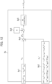
  • FIG. 12 is a phase error estimation computation unit 8a in the medium/high speed range of the embodiment of the present invention.
  • the reference numeral 8a of the drawing corresponds to the reference numeral 8 in FIG. 1 .
  • the reference numerals 1 to 7 and 9 to 11 in the drawing are the same as those in FIG. 1 .
  • a first active power computation unit 8a1 computes the first reactive power P c in accordance with Equation (16) by using the voltage command values v dc ** and v qc ** and the current detection values i dc and i qc of the d c axis and the q c axis.
  • a second active power computation unit 8a2 computes a second active power P r in accordance with Equation (17) by using the steady components i dc and i qc and the transient components dt/d(i dc ) and dt/d(i qc ) of the current detection values of the d c axis and the q c axis, the frequency estimation value ⁇ dc , and the electric circuit parameters (R*, L d *, L q *, and K e *) of the magnet motor 1.
  • a subtraction unit 8a3 receives inputs of the first active power P c and the second active power P c , and computes ⁇ P c as the deviation therebetween.
  • the deviation ⁇ P c between the active powers is input to a PI control computation unit 8a5 so as to follow "0" that is a command value 8a4 thereof, and the estimation value ⁇ c_H of the phase error ⁇ in the high speed range is computed in accordance with Equation (18) by P (proportional) + I (integral) control.
  • K p ⁇ is a proportional gain of phase error estimation computation
  • K i ⁇ is an integral gain of phase error estimation computation
  • the processor of the power conversion device 20 computes the first power (first active power P c ) from the sum (v dc **i qc +v qc **i dc ) of the products of the voltage command values and the current detection values of the same component of the d axis, which is the magnetic flux axis of the magnet motor 1, and the q axis, which is the torque axis of the magnet motor 1 (Equation (16)).
  • the processor computes the second power (second active power P c ) from the electrical circuit parameters (R*, L d *, L q *, and K e *), the steady components (current detection values i dc and i qc ) and the transient components dt/d(i dc ) and dt/d(i qc ) of the current detection values or the current command values of the d axis and the q axis, and the frequency estimation value ⁇ dc (Equation (17)).
  • the first power and the second power are active powers.
  • the estimation value ⁇ c_H of the phase deviation in the medium/high speed range can be computed on the basis of the active powers instead of the conventional extended induced voltage method.
  • the processor computes the estimation value ⁇ c_L of the phase deviation by performing proportional control and integral control such that the power deviation (deviation ⁇ Q c ) between the reactive powers is zero in the low speed range where the frequency command value ⁇ r * is less than a threshold value ( FIG. 4 and FIG. 11 ).
  • the processor computes the estimation value ⁇ c_H of the phase deviation (phase deviation ⁇ ) by performing proportional control and integral control such that the power deviation (deviation ⁇ P c ) between the reactive powers is zero in the medium/high speed range where the frequency command value ⁇ r * is equal to or larger than a threshold value.
  • FIG. 13 is a configuration diagram of a power conversion device according to an embodiment.
  • the first active power P c is computed from the voltage command values v dc ** and v qc ** and the current detection values i dc and i qc of the d c axis and the q c axis, but in the fourth embodiment, the first active power P c is computed by using the amplitude value V 1 * of the voltage command of the three-phase AC, the amplitude value ii of the current detection value, and a cosine signal of the phase ⁇ vi .
  • FIG. 14 is a phase error estimation computation unit 8b in the medium/high speed range of an embodiment of the present invention.
  • the reference numeral 8b of the drawing corresponds to the reference numeral 8 in FIG. 2 .
  • the reference numerals 1 to 7 and 9 to 11 in the drawing are the same as those in FIG. 1 .
  • the reference numerals 8b2, 8b3, 8b4, and 8b5 in FIG. 14 are the same as the reference numerals 8a2, 8a3, 8a4, and 8a5 in FIG. 12 , respectively.
  • the amplitude value V 1 * of the voltage command of the three-phase AC is obtained in accordance with Equation (12) described above
  • the amplitude value i 1 of the current detection value is obtained in accordance with Equation (13) described above
  • the phase ⁇ vi is obtained in accordance with Equation (14) described above
  • the active power P c is computed by using Equation (19).
  • the processor of the power conversion device 20 computes the first power (first active power P c ) from the product of the voltage amplitude value (amplitude value V 1 * of the voltage command) of one phase of the three-phase AC, the current amplitude value (amplitude value ii of the current detection value) of the phase, and the cosine signal cos[ ⁇ vi ] of the phase difference between the voltage command value and the current detection value of the phase (Equation (19)).
  • the processor computes the second power (second active power P c ) from the electrical circuit parameters (R*, L d *, L q *, and K e *), the steady components (current detection values i dc and i qc ) and the transient components dt/d(i dc ) and dt/d(i qc ) of the current detection values or the current command values of the d axis and the q axis, and the frequency estimation value ⁇ dc.
  • Stable and highly-accurate control of the magnet motor 1 can be realized on the basis of the cosine signal of the three-phase AC.
  • FIG. 15 is a configuration diagram of a power conversion device according to an embodiment.
  • the first to fourth embodiments are configured to set the electric circuit parameters of the magnet motor 1 in the controller (microcomputer or the like) of the power converter 2, but in the present embodiment, the state amount of control is fed back to a higher IOT controller, and then the machine-learned electric circuit parameters are re-set in the controller of the power converter.
  • the reference numeral 1 to 11 in the drawing are the same as those in FIG. 1 .
  • the reference numeral 12 denotes an IOT controller that executes machine learning.
  • the processor of the power conversion device 20 transmits the voltage command values v dc ** and v qc **, the current detection values i dc and i qc , and the estimation value ⁇ c of the phase deviation to the controller (IOT controller) of the higher device via a communication device.
  • the processor of the power conversion device 20 receives the inductances L d * and L q * of the d axis and the q axis or the induced voltage coefficient K e * of the magnet motor analyzed (machine learning) on the basis of the voltage command values v dc ** and v qc **, the current detection values i dc and i qc , and the estimation value ⁇ c of the phase deviation from the controller (IOT controller) of the higher device via the communication device.
  • the processor of the power conversion device 20 updates the electrical circuit parameters stored in a storage device of the power conversion device 20, with the received values. Accordingly, the electric circuit parameters can be automatically updated.
  • FIG. 16 is a configuration diagram of a power converter according to an embodiment.
  • the present embodiment is an embodiment in which the first embodiment is applied to a magnet motor drive system.
  • the constitutional elements of the reference numerals 1 and 5 to 11 are the same as those in FIG. 1 .
  • the magnet motor 1 as a constitutional element of FIG. 1 is driven by the power conversion device 20.
  • the constitutional elements of the reference numerals 5 to 11 in FIG. 1 are mounted as software 20a, and the constitutional elements of the reference numerals 2, 3, and 4 in FIG. 1 are mounted as hardware.
  • ⁇ chg that is the switching frequency 26 between the low speed range and the medium/high speed range
  • ⁇ c that is the control response 27 of the phase error in the low speed range
  • the software 20a can be set and changed by a higher device such as a digital operator 20b, a personal computer 28, a tablet 29, or a smartphone 30.
  • ⁇ chg that is the switching frequency 26 between the low speed range and the medium/high speed range
  • ⁇ c that is the control response 27 of the phase error in the low speed range
  • the power conversion device 20 depicted in FIG. 16 includes a storage device (for example, a non-volatile memory) for storing the threshold value (switching frequency 26, ⁇ chg ) and the control response 27 ( ⁇ c or the like) used for proportional control or integral control.
  • the power conversion device 20 includes a communication device for communicating with an input device (digital operator 20b or the like) for setting the threshold value (switching frequency 26, ( ⁇ chg ) and the control response 27 ( ⁇ c or the like), or the external devices (the personal computer 28, the tablet 29, the smartphone 30, and the like) that set the threshold value and the control response.
  • the user can easily set the threshold value (switching frequency 26, ⁇ chg ) and the control response 27 ( ⁇ c or the like) .
  • the current detection values i dc and i qc are used in Equation (6) as the first reactive power Q c and Equation (7) as the second reactive power Q c , but the current command values i d * and i q * may be used.
  • the current detection values i dc and i qc are used in Equation (16) as the first active power P c and Equation (17) as the second reactive power P c , but the current command values i d * and i q * may be used.
  • the voltage correction values ⁇ v dc and ⁇ v qc are created from the current command values i d * and i q * and the current detection values i dc and i qc , and the computation depicted in Equation (4) for adding the voltage correction values and the voltage reference value of the vector control is performed, but the intermediate current command values i d ** and i q ** depicted in Equation (20) used for the vector control computation are created from the current command values i d * and i q * and the current detection values i dc and i qc , and the vector control computation depicted in Equation (21) may be performed by using the frequency estimation value ⁇ dc and the electric circuit parameters of the magnet motor 1.
  • K pd1 is a proportional gain of current control of the d c axis
  • K id1 is an integral gain of current control of the d c axis
  • K pq1 is a proportional gain of current control of the q c axis
  • K iq1 is an integral gain of current control of the q c axis
  • T d is an electric time constant (L d /R) of the d axis
  • T q is an electric time constant (L q /R) of the q axis.
  • a voltage correction value ⁇ v d_p * of the proportional computation component of the d c axis used for the vector control computation a voltage correction value ⁇ vd_i * of the integral computation component of the d c axis, a voltage correction value ⁇ vq_p * of the proportional computation component of the q c axis, and a voltage correction value ⁇ vq_i * of the integral computation component of the q c axis are created by Equation (22), and the vector control computation depicted in Equation (23) using the frequency value estimation ⁇ dc and the electric circuit parameters of the magnet motor 1 may be performed.
  • the vector control computation depicted in Equation (24) may be performed by using K pd2 as a proportional gain of the current control of the d c axis, K id2 as an integral gain of the current control of the d c axis, K pq2 as a proportional gain of the current control of the q c axis, K iq2 as an integral gain of the current control of the q c axis, a primary delay signal i qctd of the current command value i d * of the d c axis and the current detection value i qc of the q c axis, the frequency estimation value ⁇ dc , and the electric circuit parameters of the magnet motor 1.
  • the switching element configuring the power converter 2 may be a silicon (Si) semiconductor element or a wide bandgap semiconductor element such as silicon carbide (SiC) or gallium nitride (GaN).
  • each constitutional element may be singular or multiple.
  • the position, size, shape, range, and the like of each constitutional element depicted in the drawings do not represent the actual position, size, shape, range, and the like in some cases in order to facilitate understanding of the invention. Therefore, the present invention is not necessarily limited to the positions, sizes, shapes, ranges, and the like disclosed in the drawings. Examples of the various types of information are described by expressions such as “table,” “list,” and “queue,” but the various types of information may be expressed by data structures other than these.
  • various types of information such as “XX table,” “XX list,” and “XX queue” may be “XX information.”
  • identification information expressions such as “identification information,” “identifier,” “name,” “ID,” and “number” are used, but they can be replaced with each other.
  • identification information identifier
  • name e.g., "name”
  • ID e.g., "ID”
  • number e.g., "number”
  • a computer executes a program by a processor (for example, a CPU or a GPU), and performs a process specified by the program while using a storage resource (for example, a memory), an interface device (for example, a communication port), or the like. Therefore, the main body of the process performed by executing the program may be the processor. Similarly, the main body of the process performed by executing the program may be a controller, a device, a system, a computer, or a node having a processor. The main body of the process performed by executing the program may be a computation unit, and may include a dedicated circuit for performing a specific process.
  • the dedicated circuit is a field programmable gate array (FPGA), an application specific integrated circuit (ASIC), a complex programmable logic device (CPLD), or the like.
  • the program may be installed on a computer from a program source.
  • the program source may be, for example, a program distribution server or a computer readable storage medium.
  • the program distribution server includes a processor and a storage resource for storing a program to be distributed, and the processor of the program distribution server may distribute the program to be distributed to other computers.
  • two or more programs may be realized as one program, or one program may be realized as two or more programs.
  • the present invention is not limited to the above embodiments, but includes various modified examples.
  • the above-described embodiments have been described in detail for the purpose of clearly explaining the present invention, and are not necessarily limited to those having all of the described configurations.
  • addition, deletion, or replacement of another configuration is possible for a part of a configuration of each embodiment.
  • a power conversion device for controlling the output frequency, the output voltage, and the output current of a magnet motor
  • the deviation between the phase of control and the phase of the magnetic flux of the motor is estimated such that a first power computed from the output voltage and the output current of the magnet motor follows a second power computed from electric circuit parameters of the magnet motor, steady components and transient components of the output current, and a frequency estimation value, and the frequency estimation value is controlled by using the estimation value of the relevant phase deviation.
  • C2 In a power conversion device for controlling the output frequency, the output voltage, and the output current of a magnet motor, the deviation between the phase of control and the phase of the magnetic flux of the motor is estimated such that a first reactive power computed from the output voltage and the output current of the magnet motor follows a second reactive power computed from electric circuit parameters of the magnet motor, steady components and transient components of the output current, and a frequency estimation value, and the frequency estimation value is controlled by using the estimation value of the relevant phase deviation.
  • C3 In a power conversion device for controlling the output frequency, the output voltage, and the output current of a magnet motor, the deviation between the phase of control and the phase of the magnetic flux of the motor is estimated such that a first active power computed from the output voltage and the output current of the magnet motor follows a second active power computed from electric circuit parameters of the magnet motor, steady components and transient components of the output current, and a frequency estimation value, and the frequency estimation value is controlled by using the estimation value of the relevant phase deviation.
  • C4 In a power conversion device of vector control that computes voltage command values of the d axis and the q axis by using current command values and current detection values of the d axis as the magnetic flux axis of a magnet motor and the q axis as the torque axis, and a frequency estimation value, the deviation between the phase of control and the phase of the magnetic flux of the motor is estimated such that a first reactive power obtained by multiplying the voltage command values and the current detection values of different components of the d axis and the q axis and adding them (expressed as adding in consideration of the positive and negative of the values) follows a second reactive power computed from electric circuit parameters of the magnet motor, steady components and transient components of the current detection values or the current command values of the d axis and the q axis, and a frequency estimation value, and the frequency estimation value is controlled by using the estimation value of the relevant phase deviation.
  • the deviation between the phase of control and the phase of the magnetic flux of the motor is estimated such that a first active power obtained by multiplying the voltage command values and the current detection values of the same component of the d axis and the q axis and adding them follows a second active power computed from electric circuit parameters of the magnet motor, steady components and transient components of the current detection values or the current command values of the d axis and the q axis, and the frequency estimation value, and the frequency estimation value is controlled by using the estimation value of the relevant phase deviation.
  • a phase error that is the deviation between the phase of control and the phase of the magnetic flux of the motor is estimated such that a first active power obtained by multiplying a voltage amplitude value and a current amplitude value of one phase of the three-phase AC and a cosine signal of the phase difference between the voltage command value and the current detection value follows a second active power computed from electric circuit parameters of the magnet motor, steady components and transient components of the current detection values or the current command values of the d axis and the q axis, and the frequency estimation value, and the frequency estimation value is controlled such that the estimation value of the relevant phase error follows the command value thereof.
  • the estimation computation of the phase error that is the deviation between the phase of control and the phase of the magnetic flux of the motor is performed by proportional control and integral control performed such that the deviation between the first and second reactive powers or the deviation between the first and second reactive powers is zero.
  • the estimation computation of the phase error is performed by proportional control and integral control performed such that the deviation between the first and second reactive power information is zero if the magnet motor is in the low speed range and the deviation between the first and second active power information is zero if the magnet motor is in the medium/high speed range.

Landscapes

  • Engineering & Computer Science (AREA)
  • Power Engineering (AREA)
  • Physics & Mathematics (AREA)
  • General Physics & Mathematics (AREA)
  • Theoretical Computer Science (AREA)
  • General Engineering & Computer Science (AREA)
  • Control Of Ac Motors In General (AREA)

Abstract

To provide a power conversion device capable of realizing stable and highly-accurate control of a magnet motor.
A processor of a power conversion device computes a first power (first reactive power) from voltages (voltage command values) and currents (current detection values) of a magnet motor. The processor computes a second power (second reactive power) from electric circuit parameters of the magnet motor, steady components (current detection values) and transient components of the current of the magnet motor, and a frequency estimation value of the magnet motor. The processor estimates a phase deviation (phase error) indicating the deviation (difference) between the phase of control and the phase (phase of the magnet) of the magnetic flux of the magnet motor such that the first power follows the second power. The processor computes the frequency estimation value from the estimation value of the phase deviation.

Description

    BACKGROUND OF THE INVENTION 1. Field of the Invention
  • The present invention relates to a power conversion device.
  • 2. Description of the Related Art
  • As a stable and highly-accurate control method in the low speed range of position sensorless control, as described in Patent No. 4402600 , there is a description of a technique for computing a reactive power and estimating the frequency of a magnet motor on the basis of voltage command values and current detection values given to a power converter, electric circuit parameters of the magnet motor, and a frequency estimation value.
  • PRIOR ART DOCUMENT PATENT DOCUMENT
  • Patent Document 1: Patent No. 4402600
  • SUMMARY OF THE INVENTION
  • The method described in Patent No. 4402600 includes computing two types of reactive powers (Q and Q) and computing a frequency estimation value of an inverter such that the deviation ΔQ therebetween is zero. Since the frequency estimation value can reduce the sensitivity to the winding resistance value of the magnet motor, which change being due to a temperature change, highly-accurate control characteristics can be realized. A first motor frequency is estimated by proportional integral (PI) control by using a reactive power in the low speed range, and a second motor frequency is estimated by the PI control such that a phase error (between the phase of control and the phase of the magnet motor) directly estimated by using an extended induced voltage follows zero in the medium/high speed range. Therefore, when the first motor frequency and the second motor frequency are switched to each other, a torque shock due to a current change may occur if there is a difference between the two frequencies.
  • An object of the present invention is to provide a power conversion device capable of realizing stable and highly-accurate control of a magnet motor.
  • In order to achieve the above object, the present invention provides a power conversion device including a processor that computes a first power from a voltage and a current of a magnet motor, computes a second power from electric circuit parameters of the magnet motor, steady components and transient components of the current of the magnet motor, and a frequency estimation value of the magnet motor, estimates a phase deviation indicating a deviation between a phase of control and a phase of a magnetic flux of the magnet motor such that the first power follows the second power, and/or computes the frequency estimation value from an estimation value of the phase deviation.
  • According to the present invention, stable and highly-accurate control of a magnet motor can be realized. The problems, configurations, and effects other than those described above will be clarified by the following description of embodiments.
  • BRIEF DESCRIPTION OF THE DRAWINGS
    • FIG. 1 is a configuration diagram of a power conversion device according to an embodiment;
    • FIG. 2 is a configuration diagram of a phase error estimation computation unit in the high speed range where an extended induced voltage is used;
    • FIG. 3 is a configuration diagram of a phase error estimation computation unit in the low speed range according to the embodiment;
    • FIG. 4 is a configuration diagram of a frequency and phase estimation computation unit according to the embodiment;
    • FIG. 5 depicts control characteristics in the case where an extended induced voltage method in the medium/high speed range is used in the low speed range;
    • FIG. 6 depicts control characteristics in the case where the present invention is used in the low speed range;
    • FIG. 7 depicts control characteristics in the case where the present invention is used for switching between the low speed range and the medium/high speed range;
    • FIG. 8 is a configuration diagram for confirming the manifestation of the present invention;
    • FIG. 9 is a configuration diagram of a power conversion device according to another embodiment;
    • FIG. 10 is a configuration diagram of another phase error estimation computation unit in the low speed range according to the embodiment;
    • FIG. 11 is a configuration diagram of a power conversion device according to still another embodiment;
    • FIG. 12 is a configuration diagram of another phase error estimation computation unit in the high speed range according to the embodiment;
    • FIG. 13 is a configuration diagram of a power conversion device according to still another embodiment;
    • FIG. 14 is a configuration diagram of still another phase error estimation computation unit in the high speed range according to the embodiment;
    • FIG. 15 is a configuration diagram of another power conversion device according to the embodiment; and
    • FIG. 16 is a configuration diagram of still another power conversion device according to the embodiment.
    DESCRIPTION OF THE PREFERRED EMBODIMENTS
  • In position sensorless control in which an encoder for detecting the magnet phase of a magnet motor and the like are omitted, the present embodiments realize stable and highly-accurate control characteristics even in a low speed range of, for example, approximately 10% of the base frequency from a stop. In the present embodiments, a phase error is estimated from the deviation between two types of reactive powers in the low speed range as is the case with the medium/high speed range. By estimating a motor frequency such that the estimation value of the relevant phase error follows the command value thereof, a torque shock is prevented and stable and highly-accurate control characteristics are realized without adjusting electric circuit parameters and control gains of the magnet motor set in a controller.
  • It should be noted that the present embodiments will be described below in detail by using the drawings. The same reference characters (signs) are given to the common configurations in each drawing. In addition, each embodiment to be described below is not limited to the illustrated examples.
  • First Embodiment
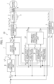
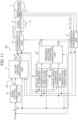
  • FIG. 1 depicts a configuration diagram of a power conversion device according to an embodiment.
  • A magnet motor 1 outputs a motor torque obtained by combining a torque component due to the magnetic flux of a permanent magnet and a torque component due to the inductance of an armature winding.
  • A power converter 2 outputs voltage values proportional to voltage command values vu*, vv*, and vw* of three-phase AC, and varies an output voltage value and an output frequency value to the magnet motor 1. Although the power converter 2 of the present embodiment includes a controller (microcomputer or the like), a power conversion device 20 described later may include a controller. The controller is configured using a memory (storage device), a CPU (processor), an input/output circuit (communication device), and the like.
  • A DC power supply 3 supplies a DC voltage to the power converter 2.
  • A current detector 4 outputs iuc, ivc, and iwc that are the detection values of three-phase AC currents iu, iv, and iw of the magnet motor 1. In addition, the current detector 4 detects the AC currents of two phases among the three phases of the magnet motor 1, which are the u phase and the w phase, for example, and the AC current of the v phase may be obtained from the AC condition (iu + iv + iw = 0) as iv = -(iu + iw).
  • A coordinate conversion unit 5 outputs current detection values idc and iqc of the d axis and the q axis from the detection values iuc, ivc, and iwc of the three-phase AC currents iu, iv, and iw and a phase estimation value θdc.
  • A speed control computation unit 6 computes a torque command value t* on the basis of a frequency command value ωr* and a frequency estimation value ωdc, and divides it by a torque coefficient, so that a current command value iq* of the q axis is output.
  • A vector control computation unit 7 outputs voltage command values vdc** and vqc** of the d axis and the q axis computed on the basis of the current command values id* and iq* and the current detection values idc and iqc of the d axis and the q axis, the frequency estimation value ωdc, and electric circuit parameters of the magnet motor 1.
  • A phase error estimation computation unit 8 in the medium/high speed range outputs an estimation value Δθc_H of a phase error Δθ, which is the deviation between the phase θdc of control and the phase θd of the magnet of the magnet motor 1 in the medium/high speed range, by using voltage command values vdc** and vqc** of the dc axis and the qc axis that are the control axes, the frequency estimation value ωdc, the current detection values idc and iqc, and the electric circuit parameters of the magnet motor 1.
  • A phase error estimation computation unit 9 in the low speed range computes an estimation value Δθc_L of the phase error Δθ, which is the deviation between the phase θdc of control and the phase θd of the magnet of the magnet motor 1 in the low speed range, by using the voltage command values vdc** and vqc** of the dc axis and the qc axis that are the control axes, the frequency estimation value ωdc, the current detection values idc and iqc, and the electric circuit parameters of the magnet motor 1.
  • A frequency and phase estimation computation unit 10 outputs the frequency estimation value ωdc and the phase estimation value θdc on the basis of the estimation value Δθc_L of the phase error in the low speed range or the estimation value Δθc_H of the phase error in the medium/high speed range.
  • A coordinate conversion unit 11 outputs the voltage command values vdc** and vqc** of the dc axis and the qc axis and the voltage command values vu*, vv*, and vw* of the three-phase AC from the phase estimation value θdc.
  • First, the basic operation of a sensorless vector control system in the case where the phase error estimation computation unit 9 in the low speed range, which is a feature of the present embodiment, is used will be described.
  • The speed control computation unit 6 computes the torque command t* and the current command value iq* of the q axis in accordance with Equation (1) by proportional control and integral control such that a frequency estimation value ωr (=ωdc) follows the frequency command value ωr*. It should be noted that in the following various equations, the frequency estimation value will be described as ωr or ωdc in some cases.
    [Equation 1] τ = ω r ω r K sp + K si s i q = τ 3 / 2 P m K e + L d L q i d )
    Figure imgb0001
  • Here, Ksp is a proportional gain of speed control, Ksi is an integral gain of speed control, Pm is the number of pole pairs, Ke is an induced voltage coefficient, Ld is a d-axis inductance, Lq is a q-axis inductance, and * is a set value.
  • First, the vector control computation unit 7 outputs voltage reference values vdc* and vqc* of the dc axis and the qc axis in accordance with Equation (2) by using a set value R* of the winding resistance that is an electric circuit parameter of the magnet motor 1, a set value Ld* of the d-axis inductance, a set value Lq* of the q-axis inductance, a value Ke* of the induced voltage coefficient, the current command values id* and iq* of the dc axis and the qc axis, and the frequency estimation value ωr (=ωdc).
    [Equation 2] v dc = R i d ω dc L q 1 1 + Tacr s i q v qc = R i q dc L d 1 1 + Tacr s i d + K e
    Figure imgb0002
  • Here, Tacr is a response time constant of current control.
  • Second, the vector control computation unit 7 computes voltage correction values Δvdc and Δvqc of the dc axis and the qc axis in accordance with Equation (3) by proportional control and integral control such that the current detection values idc and iqc of each component follow the current command values id* and iq* of the dc axis and the qc axis.
    [Equation 3] Δv dc = K pd + K id s i d i dc Δv qc = K pq + K iq s i q i qc
    Figure imgb0003
  • Here, Kpd is a proportional gain of current control of the dc axis, Kid is an integral gain of current control of the dc axis, Kpq is a proportional gain of current control of the qc axis, and Kiq is an integral gain of current control of the qc axis. The vector control computation unit 7 further computes the voltage command values vdc** and vqc** of the dc axis and the qc axis in accordance with Equation (4).
    [Equation 4] v dc = v dc + Δv dc v qc = v qc + Δv qc
    Figure imgb0004
  • FIG. 2 depicts a block of the phase error estimation computation unit 8 in the medium/high speed range. The phase error estimation computation unit 8 in the medium/high speed range computes the estimation value Δθc_H of the phase error in the medium/high speed range in accordance with Equation (5) of an extended induced voltage denoted by the reference numeral 81, on the basis of the voltage command values vdc** and vqc** and the current detection values idc and iqc of the dc axis and the qc axis, and the electric circuit parameters (R* and Lq*) of the magnet motor 1.
    [Equation 5] Δθ c_H = tan 1 v dc R i dc + ω dc L q i qc v qc R i qc ω dc L q i dc
    Figure imgb0005
  • Here, the phase error estimation computation unit 9 in the low speed range, which is a feature of the present embodiment of the present invention, will be described.
  • FIG. 3 depicts a block of the phase error estimation computation unit 9 in the low speed range. The phase error estimation computation unit 9 in the low speed range computes a first reactive power Qc in accordance with Equation (6) by using the voltage command values vdc** and vqc** and the current detection values idc and iqc of the dc axis and the qc axis in a first reactive power computation unit 91.
    [Equation 6] Q c = v dc i qc v qc i dc
    Figure imgb0006
  • A second reactive power computation unit 92 computes a second reactive power Qc in accordance with Equation (7) by using steady components idc and iqc and transient components dt/d(idc) and dt/d(iqc) of the current detection values of the dc axis and the qc axis, the frequency estimation value ωdc, and the electric circuit parameters (Ld*, Lq*, and Ke*) of the magnet motor 1.
    [Equation 7] Q c = ω dc L d i dc 2 + L q i qc 2 ω dc K e + L d i dc + L d i qc d / dt i dc L q i dc d / dt i qc
    Figure imgb0007
  • A subtraction unit 93 receives inputs of the first reactive power Qc and the second reactive power Qc, and computes ΔQc as the deviation therebetween. The deviation ΔQc between the reactive powers is input to a PI control computation unit 95 so as to follow "0" that is a command value 94 thereof, and the estimation value Δθc_L of the phase error Δθ in the low speed range is computed in accordance with Equation (8) by proportional (P) + integral (I) control computation.
    [Equation 8] Δθ c_L = K + K s 0 ΔQ c
    Figure imgb0008
  • Here, K is a proportional gain of phase error estimation computation, and K is an integral gain of phase error estimation computation.
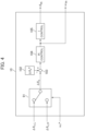
  • In addition, the frequency and phase estimation computation unit 10, which is a feature of the embodiment of the present invention, will be described. FIG. 4 depicts a block of the frequency and phase estimation computation unit 10.
  • A switching unit 101 receives inputs of the estimation value Δθc_L of the phase error in the low speed range, the estimation value Δθc_H of the phase error in the medium/high speed range, and the frequency command value ωr*, and outputs Δθc = Δθc_L in the case of the low speed range and Δθc = Δθc_H in the case of the medium/high speed range, as the estimation value Δθc of the phase error according to the magnitude of the frequency command value ωr*.
  • The subtraction unit 103 inputs the estimation value Δθc of the phase error described above to the PI control computation unit 104 so as to follow the command value Δθc* denoted by the reference numeral 102, the frequency estimation value ωdc is computed in accordance with Equation (9) by the proportional (P) + integral (I) computation, and the phase estimation value θdc is computed in accordance with Equation (10) by an I control computation unit 105.
    [Equation 9] ω dc = K p pll + Ki pll s Δθ c Δθ c
    Figure imgb0009

    [Equation 10] θ dc = 1 s ω dc
    Figure imgb0010
  • Here, Kppll is a proportional gain of PLL control, and Kipll is an integral gain of PLL control.
  • Next, the principle in which the embodiment of the present invention provides stable and highly-accurate control characteristics will be described. FIG. 5 depicts control characteristics in the case where the phase error estimation computation unit 9 in the low speed range of the present invention is not used (Δθc_H is used). The frequency command value ωr* is set to 2% of the base frequency. FIG. 5 depicts simulation results of (a) R*/R=1 (reference) when there is no error and (b) R*/R=0.5 when there is an error, in the voltage command values vdc** and vdc** of the dc axis and the qc axis depicted in Equation (2) and the set value R* of the resistance value R included in the computation formula of the phase error in the medium/high speed range depicted in Equation (5).
  • In the drawing, the upper row indicates a load torque τL, the middle row indicates a frequency command ωr* and a motor frequency ωr, and the lower row indicates a phase error Δθ. In the drawing, the load torque application that starts with the point A of the time is changed in a ramp-like manner to reach 100% at the point B of the time, and then the load torque application state is kept as it is on the right side of the point B.
  • In the setting of (a) R*/R=1 (reference), the phase error Δθ is zero in the steady state, and the motor frequency ωr matches the frequency command ωr*. In the setting of (b) R*/R=0.5, the phase error Δθ increases to "negative," the motor frequency ωr is stagnant around zero, and the magnet motor 1 is stepped out.
  • In the embodiment of the present invention, the first reactive power Qc is computed in accordance with Equation (6) by using the voltage command values vdc* and vqc* and the current detection values idc and iqc of the dc axis and the qc axis, and the second reactive power Qc is computed in accordance with Equation (7) by using the steady components idc and iqc and the transient components dt/d(idc) and dt/d(iqc) of the current detection values of the dc axis and the qc axis, the frequency estimation value ωdc, and the set values (Ld*, Lq*, and Ke*) of the electric circuit parameters of the magnet motor 1. By automatically adjusting the estimation value Δθc_L of the phase error in the low speed range in accordance with Equation (8) such that the deviation between Qc and Qc follows zero, and by using the estimation value Δθc_L in the frequency and phase estimation computation unit 10, the sensitivity to the resistance value can be reduced and the control characteristics can be improved.
  • FIG. 6 depicts control characteristics in the low speed range according to the present embodiment. In the setting of R*/R=0.5, the phase error estimation computation unit 9 in the low speed range and the frequency and phase estimation computation unit 10 are operated to apply the load torque similar to that in FIG. 4. Since the estimation value Δθc_L of the phase error is computed from the reactive power that is less sensitive to the resistance value R, the actual phase error Δθ can be suppressed to zero even in the setting of R*/R=0.5.
  • Further, FIG. 7 depicts control characteristics in which the frequency command value ωr* is accelerated from 2% to 20% of the base frequency and decelerated from 20% to 2% by using the present invention. At this time, ωr* is 10% in magnitude, and the estimation value of the phase error is switched between the low speed range and the medium/high speed range. The estimation value of the phase error is computed in accordance with Equations (6) to (8) in the low speed range where ωr* is less than 10%, and is computed in accordance with Equation (5) in the medium/high speed range where ωr* is equal to or more than 10%.
  • The speed is switched from the low speed range to the medium/high speed range in the region C of the drawing, and the speed is switched from the medium/high speed range to the low speed range in the region D. Viewing the phase error Δθ in the lower row, it can be understood that there is no shock in the motor frequency ωr although the magnitude slightly changes at the switching timing, and the effect of the embodiment of the present invention is obvious.
  • In the present embodiment, as an example, ωr* is 10% in magnitude, and the estimation value of the phase error is switched between the low speed range and the medium/high speed range, but there is no problem even if the value is 0 or more and 10% or less. In addition, the estimation value Δθc_L of the phase error in the low speed range is multiplied by a taper gain G_L that changes between "1" and "0", and the estimation value Δθc_H of the phase error in the medium/high speed range is multiplied by a taper gain G_H that changes between "0" and "1", so that the average value of the estimation values of the phase error may be Δθc.
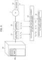
  • Here, a verification method in the case where the present embodiment is adopted will be described by using FIG. 8. A voltage detector 21 and a current detector 22 are attached to the power conversion device 20 that drives the magnet motor 1, and an encoder 23 is attached to the shaft of the magnet motor 1. It should be noted that the power conversion device 20 includes the power converter 2, a digital operator 20b (user interface serving as an input device and a display device), and the like.
  • The voltage detection values (vuc, vvc, and vwc) of the three-phase AC, which are the outputs of the voltage detector 21, the current detection values (iuc, ivc, and iwc) of the three-phase AC, and the position θ, which is the output of the encoder, are input to a calculation unit 24 for voltage/current of the vector component, and a detection value ωrc is computed, which is obtained by differentiating the vector voltage components vdc and vqc, the vector current components idc and iqc, and the position θ.
  • A phase error Δθ_cal is computed by using Equation (11) in an observation unit 25 for waveforms at various points.
    [Equation 11] Δθ _ cal = b ± b 2 4 ac 2 a a = L d L q i qc 2 i dc 2 b = 2 L d L q i dc 2 + K e i qc c = L q L q i qc 2 L d L d i dc 2 K e * K e i dc )
    Figure imgb0011
  • It is obvious that the present invention has been adopted if Δθ_cal in Equation (11), which is computed by changing the magnitudes of the parameters (R*, Ld*, Lq*, and Ke*) set in the controller of the power converter 2, matches the actual phase error Δθ.
  • The main features of the first embodiment can also be summarized as follows.
  • As depicted in FIG. 3, the processor of the power conversion device 20 computes the first power (first reactive power Qc) from the voltages (voltage command values vdc** and vqc**) and the currents (current detection values idc and iqc) of the magnet motor 1 (Equation (6)). The processor computes the second power (second reactive power Qc) from the electric circuit parameters (Ld*, Lq*, and Ke*) of the magnet motor 1, the steady components (current detection values idc and iqc) and the transient components dt/d(idc) and dt/d(iqc) of the current of the magnet motor 1, and the frequency estimation value ωdc of the magnet motor 1 (Equation (7)). The processor estimates the phase deviation (phase error Δθ) indicating the deviation (difference) between the phase θdc of control and the phase (phase θd of the magnet) of the magnetic flux of the magnet motor such that the first power follows the second power. As depicted in FIG. 4, the processor computes the frequency estimation value ωdc from the estimation values (Δθc_L and Δθc_H) of the phase deviation. In the present embodiment, the first power and the second power are reactive powers.
  • Since the second power includes the transient components of the current of the magnet motor 1, the accuracy of the phase deviation (phase error Δθ) and the frequency estimation value ωdc is secured even when the frequency of the magnet motor 1 is switched. Accordingly, stable and highly-accurate control characteristics can be realized without adjusting the electric circuit parameters and the control gains of the magnet motor 1. In addition, even if the responsiveness of the speed control is enhanced, the oscillation of the current (q-axis current) when the frequency of the magnet motor 1 is switched is suppressed. Accordingly, a torque shock can be suppressed. Since the first power and the second power do not include the winding resistance value, the deterioration of the accuracy of the phase deviation (phase error Δθ) and the frequency estimation value ωdc due to a change in the winding resistance value accompanying a temperature change in the low speed range is suppressed. Accordingly, highly-accurate control of the magnet motor 1 can be realized regardless of the temperature change.
  • More specifically, as depicted in FIG. 3, the processor computes the first power (first reactive power Qc) from the difference (vdc**iqc - vqc**idc) between the products of the voltage command values and the current detection values of the different components of the d axis, which is the magnetic flux axis of the magnet motor 1, and the q axis, which is the torque axis of the magnet motor 1. The processor computes the second power (second reactive power Qc) from the electrical circuit parameters (Ld*, Lq*, and Ke*), the steady components (current detection values idc and iqc) and the transient components dt/d(idc) and dt/d(iqc) of the current detection values or the current command values of the d axis and the q axis, and the frequency estimation value ωdc. Accordingly, stable and highly-accurate control of the magnet motor 1 can be realized in the power conversion device of the vector control.
  • In the present embodiment, the processor computes the estimation value Δθc_L of the phase deviation (phase error Δθ) by performing proportional control and integral control such that the power deviation (deviation ΔQc between the reactive powers) indicating the deviation between the first power (first reactive power Qc) and the second power (second reactive power Qc) is zero. Accordingly, the estimation value Δθc_L of the phase deviation (phase error Δθ) can be computed on the basis of the power deviation.
  • As depicted in FIG. 3, the processor computes the estimation value Δθc_L of the phase deviation by performing proportional control and integral control such that the power deviation (deviation ΔQc) between the reactive powers is zero in the low speed range where the frequency command value ωr* is less than a threshold value. As depicted in FIG. 2, the processor computes the estimation value Δθc_H of the phase deviation by using an extended induced voltage method in the medium/high speed range where the frequency command value ωr* is equal to or larger than a threshold value. Accordingly, stable and highly-accurate control of the magnet motor 1 can be realized in all the speed ranges.
  • Second Embodiment
  • FIG. 9 is a configuration diagram of a power conversion device according to an embodiment.
  • In the first embodiment, the phase error estimation computation unit 9 in the low speed range computes the first reactive power Qc from the voltage command values vdc** and vqc** and the current detection values idc and iqc of the dc axis and the qc axis, but in the present embodiment, the first reactive power Qc is computed by using an amplitude value V1* of the voltage command of the three-phase AC, an amplitude value ii of the current detection value, and a sine signal of a phase θvi. The reference numerals 1 to 8, 10, and 11 in the drawing are the same as those in FIG. 1.
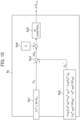
  • FIG. 10 is a configuration diagram of a phase error estimation computation unit 9a in the low speed range of the embodiment of the present invention. The reference numeral 9a of the drawing corresponds to the reference numeral 9 in FIG. 1. In addition, the reference numerals 9a2, 9a3, 9a4, and 9a5 in FIG. 10 are the same as the reference numerals 92, 93, 94, and 95 in FIG. 3, respectively. In the drawing, in 9a1, the amplitude value V1* of the voltage command of the three-phase AC is obtained in accordance with Equation (12), the amplitude value ii of the current detection value is obtained in accordance with Equation (13), the phase θvi is obtained in accordance with Equation (14), and the reactive power Qc is computed by using Equation (15).
    [Equation 12] v 1 = v dc 2 + v qc 2
    Figure imgb0012

    [Equation 13] i 1 = i dc 2 + i qc 2
    Figure imgb0013

    [Equation 14] θ vi = tan 1 v dc v qc + tan 1 i dc i qc
    Figure imgb0014

    [Equation 15] Q c = v 1 i 1 sin θ vi
    Figure imgb0015
  • Even if the present embodiment is used, highly-accurate control characteristics can be realized as similar to the first embodiment.
  • The main features of the second embodiment can also be summarized as follows.
  • As depicted in FIG. 10, the processor of the power conversion device 20 computes the first power (first reactive power Qc) from the product of the voltage amplitude value (amplitude value V1* of the voltage command) of one phase of the three-phase AC, the current amplitude value (amplitude value ii of the current detection value) of the phase, and the sine signal sin [θvi] of the phase difference between the voltage command value and the current detection value of the phase (Equation (15)). The processor computes the second power (second reactive power Qc) from the electrical circuit parameters (Ld*, Lq*, and Ke*), the steady components (current detection values idc and iqc) and the transient components dt/d(idc) and dt/d(iqc) of the current detection values or the current command values of the d axis and the q axis, and the frequency estimation value ωdc. Stable and highly-accurate control of the magnet motor 1 can be realized on the basis of the sine signal of the three-phase AC.
  • Third Embodiment
  • FIG. 11 is a configuration diagram of a power conversion device according to an embodiment.
  • In the first embodiment, the phase error estimation computation unit 8 in the medium/high speed range computes the estimation value Δθc_H of the phase error in the medium/high speed range in accordance with Equation (5), but in the third embodiment, a first active power Pc is computed from the voltage command values vdc** and vqc** and the current detection values idc and iqc of the dc axis and the qc axis.
  • FIG. 12 is a phase error estimation computation unit 8a in the medium/high speed range of the embodiment of the present invention. The reference numeral 8a of the drawing corresponds to the reference numeral 8 in FIG. 1. The reference numerals 1 to 7 and 9 to 11 in the drawing are the same as those in FIG. 1.
  • In the phase error estimation computation unit 8a of the drawing, a first active power computation unit 8a1 computes the first reactive power Pc in accordance with Equation (16) by using the voltage command values vdc** and vqc** and the current detection values idc and iqc of the dc axis and the qc axis.
    [Equation 16] P c = v dc i dc + v qc i qc
    Figure imgb0016
  • A second active power computation unit 8a2 computes a second active power Pr in accordance with Equation (17) by using the steady components idc and iqc and the transient components dt/d(idc) and dt/d(iqc) of the current detection values of the dc axis and the qc axis, the frequency estimation value ωdc, and the electric circuit parameters (R*, Ld*, Lq*, and Ke*) of the magnet motor 1.
    [Equation 17] P C = R i dc 2 + i qc 2 + d / dt i dc L d i dc + d / dt i qc L q i qc + ω dc L d L q i dc i qc + ω dc K e i qc
    Figure imgb0017
  • A subtraction unit 8a3 receives inputs of the first active power Pc and the second active power Pc, and computes ΔPc as the deviation therebetween. The deviation ΔPc between the active powers is input to a PI control computation unit 8a5 so as to follow "0" that is a command value 8a4 thereof, and the estimation value Δθc_H of the phase error Δθ in the high speed range is computed in accordance with Equation (18) by P (proportional) + I (integral) control.
    [Equation 18] Δθ c_H = K + K s 0 ΔP c
    Figure imgb0018
  • Here, K is a proportional gain of phase error estimation computation, and K is an integral gain of phase error estimation computation.
  • The main features of the third embodiment can also be summarized as follows.
  • As depicted in FIG. 12, the processor of the power conversion device 20 computes the first power (first active power Pc) from the sum (vdc**iqc+vqc**idc) of the products of the voltage command values and the current detection values of the same component of the d axis, which is the magnetic flux axis of the magnet motor 1, and the q axis, which is the torque axis of the magnet motor 1 (Equation (16)). The processor computes the second power (second active power Pc) from the electrical circuit parameters (R*, Ld*, Lq*, and Ke*), the steady components (current detection values idc and iqc) and the transient components dt/d(idc) and dt/d(iqc) of the current detection values or the current command values of the d axis and the q axis, and the frequency estimation value ωdc (Equation (17)). In the present embodiment, the first power and the second power are active powers.
  • Accordingly, in the power conversion device of the vector control, the estimation value Δθc_H of the phase deviation in the medium/high speed range can be computed on the basis of the active powers instead of the conventional extended induced voltage method.
  • As similar to the first embodiment, the processor computes the estimation value Δθc_L of the phase deviation by performing proportional control and integral control such that the power deviation (deviation ΔQc) between the reactive powers is zero in the low speed range where the frequency command value ωr* is less than a threshold value (FIG. 4 and FIG. 11). As depicted in FIG. 12, the processor computes the estimation value Δθc_H of the phase deviation (phase deviation Δθ) by performing proportional control and integral control such that the power deviation (deviation ΔPc) between the reactive powers is zero in the medium/high speed range where the frequency command value ωr* is equal to or larger than a threshold value.
  • Accordingly, stable and highly-accurate control of the magnet motor 1 can be realized in all the speed ranges.
  • Fourth Embodiment
  • FIG. 13 is a configuration diagram of a power conversion device according to an embodiment.
  • In the third embodiment, the first active power Pc is computed from the voltage command values vdc** and vqc** and the current detection values idc and iqc of the dc axis and the qc axis, but in the fourth embodiment, the first active power Pc is computed by using the amplitude value V1* of the voltage command of the three-phase AC, the amplitude value ii of the current detection value, and a cosine signal of the phase θvi.
  • FIG. 14 is a phase error estimation computation unit 8b in the medium/high speed range of an embodiment of the present invention. The reference numeral 8b of the drawing corresponds to the reference numeral 8 in FIG. 2. The reference numerals 1 to 7 and 9 to 11 in the drawing are the same as those in FIG. 1.
  • The reference numerals 8b2, 8b3, 8b4, and 8b5 in FIG. 14 are the same as the reference numerals 8a2, 8a3, 8a4, and 8a5 in FIG. 12, respectively. In FIG. 14, in 8b1, the amplitude value V1* of the voltage command of the three-phase AC is obtained in accordance with Equation (12) described above, the amplitude value i1 of the current detection value is obtained in accordance with Equation (13) described above, the phase θvi is obtained in accordance with Equation (14) described above, and the active power Pc is computed by using Equation (19).
    [Equation 19] P c = v 1 i 1 cos θ vi
    Figure imgb0019
  • Even if the present embodiment is used, highly-accurate control characteristics can be realized as similar to the first embodiment.
  • The main features of the fourth embodiment can also be summarized as follows.
  • As depicted in FIG. 14, the processor of the power conversion device 20 computes the first power (first active power Pc) from the product of the voltage amplitude value (amplitude value V1* of the voltage command) of one phase of the three-phase AC, the current amplitude value (amplitude value ii of the current detection value) of the phase, and the cosine signal cos[θvi] of the phase difference between the voltage command value and the current detection value of the phase (Equation (19)). The processor computes the second power (second active power Pc) from the electrical circuit parameters (R*, Ld*, Lq*, and Ke*), the steady components (current detection values idc and iqc) and the transient components dt/d(idc) and dt/d(iqc) of the current detection values or the current command values of the d axis and the q axis, and the frequency estimation value ωdc. Stable and highly-accurate control of the magnet motor 1 can be realized on the basis of the cosine signal of the three-phase AC.
  • Fifth Embodiment
  • FIG. 15 is a configuration diagram of a power conversion device according to an embodiment.
  • The first to fourth embodiments are configured to set the electric circuit parameters of the magnet motor 1 in the controller (microcomputer or the like) of the power converter 2, but in the present embodiment, the state amount of control is fed back to a higher IOT controller, and then the machine-learned electric circuit parameters are re-set in the controller of the power converter.
  • The reference numeral 1 to 11 in the drawing are the same as those in FIG. 1. The reference numeral 12 denotes an IOT controller that executes machine learning.
  • In the present embodiment, the voltage command values vdc** and vqc**, the current detection values idc and iqc, and the estimation value Δθc of the phase error are fed back to the higher IOT controller 12, and then the machine-learned electric circuit parameters (R*, Ld*, Lq*, and Ke*) are re-set in the controller of the power converter 2.
  • Even if the present embodiment is used, more stable and highly-accurate control characteristics can be realized as similar to the first embodiment.
  • The main features of the fifth embodiment can also be summarized as follows.
  • The processor of the power conversion device 20 transmits the voltage command values vdc** and vqc**, the current detection values idc and iqc, and the estimation value Δθc of the phase deviation to the controller (IOT controller) of the higher device via a communication device.
  • The controller of the higher device analyzes (machine learning) the values received from the power conversion device 20 and transmits the analysis result to the power conversion device 20.
  • As depicted in FIG. 15, the processor of the power conversion device 20 receives the inductances Ld* and Lq* of the d axis and the q axis or the induced voltage coefficient Ke* of the magnet motor analyzed (machine learning) on the basis of the voltage command values vdc** and vqc**, the current detection values idc and iqc, and the estimation value Δθc of the phase deviation from the controller (IOT controller) of the higher device via the communication device. The processor of the power conversion device 20 updates the electrical circuit parameters stored in a storage device of the power conversion device 20, with the received values. Accordingly, the electric circuit parameters can be automatically updated.
  • Sixth Embodiment
  • FIG. 16 is a configuration diagram of a power converter according to an embodiment. The present embodiment is an embodiment in which the first embodiment is applied to a magnet motor drive system. In the drawing, the constitutional elements of the reference numerals 1 and 5 to 11 are the same as those in FIG. 1.
  • The magnet motor 1 as a constitutional element of FIG. 1 is driven by the power conversion device 20. In the power conversion device 20, the constitutional elements of the reference numerals 5 to 11 in FIG. 1 are mounted as software 20a, and the constitutional elements of the reference numerals 2, 3, and 4 in FIG. 1 are mounted as hardware. In addition, "ωchg that is the switching frequency 26 between the low speed range and the medium/high speed range," and "ωc that is the control response 27 of the phase error in the low speed range" of the software 20a can be set and changed by a higher device such as a digital operator 20b, a personal computer 28, a tablet 29, or a smartphone 30.
  • If the present embodiment is applied to the magnet motor drive system, highly-accurate control characteristics can be realized in the position sensorless vector control. In addition, "ωchg that is the switching frequency 26 between the low speed range and the medium/high speed range," and "ωc that is the control response 27 of the phase error in the low speed range" may be set on a field bus of a programmable logic controller, a local area network connected to a computer, an IOT controller, or the like.
  • Further, although the present embodiment is disclosed by using the first embodiment, the second to fifth embodiments may be used.
  • The main features of the sixth embodiment can also be summarized as follows.
  • The power conversion device 20 depicted in FIG. 16 includes a storage device (for example, a non-volatile memory) for storing the threshold value (switching frequency 26, ωchg) and the control response 27 (ωc or the like) used for proportional control or integral control. The power conversion device 20 includes a communication device for communicating with an input device (digital operator 20b or the like) for setting the threshold value (switching frequency 26, (ωchg) and the control response 27 (ωc or the like), or the external devices (the personal computer 28, the tablet 29, the smartphone 30, and the like) that set the threshold value and the control response.
  • Accordingly, the user can easily set the threshold value (switching frequency 26, ωchg) and the control response 27 (ωc or the like) .
  • In the first to fifth embodiments, the current detection values idc and iqc are used in Equation (6) as the first reactive power Qc and Equation (7) as the second reactive power Qc, but the current command values id* and iq* may be used. In addition, the current detection values idc and iqc are used in Equation (16) as the first active power Pc and Equation (17) as the second reactive power Pc, but the current command values id* and iq* may be used.
  • Further, in the first to fifth embodiments, the voltage correction values Δvdc and Δvqc are created from the current command values id* and iq* and the current detection values idc and iqc, and the computation depicted in Equation (4) for adding the voltage correction values and the voltage reference value of the vector control is performed, but the intermediate current command values id** and iq** depicted in Equation (20) used for the vector control computation are created from the current command values id* and iq* and the current detection values idc and iqc, and the vector control computation depicted in Equation (21) may be performed by using the frequency estimation value ωdc and the electric circuit parameters of the magnet motor 1.
    [Equation 20] i d = K pd1 + K id1 s i d i dc i q = K pq1 + K iq1 s i q i qc
    Figure imgb0020

    [Equation 21] v dc = R i d ω r L q 1 1 + T q s i q v qc = R i q + ω r L d 1 1 + T d s i d + ω r Ke
    Figure imgb0021
  • Here, Kpd1 is a proportional gain of current control of the dc axis, Kid1 is an integral gain of current control of the dc axis, Kpq1 is a proportional gain of current control of the qc axis, Kiq1 is an integral gain of current control of the qc axis, Td is an electric time constant (Ld/R) of the d axis, and Tq is an electric time constant (Lq/R) of the q axis.
  • Alternatively, from the current command values id* and iq* and the current detection values idc and iqc, a voltage correction value Δvd_p* of the proportional computation component of the dc axis used for the vector control computation, a voltage correction value Δvd_i* of the integral computation component of the dc axis, a voltage correction value Δvq_p* of the proportional computation component of the qc axis, and a voltage correction value Δvq_i* of the integral computation component of the qc axis are created by Equation (22), and the vector control computation depicted in Equation (23) using the frequency value estimation ωdc and the electric circuit parameters of the magnet motor 1 may be performed.
    [Equation 22] Δv d _ p = K pd2 i d i dc Δv d _ i = K id2 s i d i dc Δv q _ p = K pq2 i q i qc Δv q _ i = K iq2 s i q i qc
    Figure imgb0022

    [Equation 23] v dc = Δv d_p + Δv d_i ω r L q R Δv q_i v qc = Δv q_p + Δv q_i r L d R Δv d_i + ω r K e
    Figure imgb0023
  • Here, the vector control computation depicted in Equation (24) may be performed by using Kpd2 as a proportional gain of the current control of the dc axis, Kid2 as an integral gain of the current control of the dc axis, Kpq2 as a proportional gain of the current control of the qc axis, Kiq2 as an integral gain of the current control of the qc axis, a primary delay signal iqctd of the current command value id* of the dc axis and the current detection value iqc of the qc axis, the frequency estimation value ωdc, and the electric circuit parameters of the magnet motor 1.
    [Equation 24] v dc = R i d ω r L q i qctd v qc = R i qctd r L d i d + ω r Ke
    Figure imgb0024
  • It should be noted that in the first to sixth embodiments, the switching element configuring the power converter 2 may be a silicon (Si) semiconductor element or a wide bandgap semiconductor element such as silicon carbide (SiC) or gallium nitride (GaN).
  • The above embodiments are examples for explaining the present invention and have been omitted and simplified as appropriate in order to clarify the explanation. The present invention can be carried out in various other forms. Unless otherwise specified, each constitutional element may be singular or multiple. The position, size, shape, range, and the like of each constitutional element depicted in the drawings do not represent the actual position, size, shape, range, and the like in some cases in order to facilitate understanding of the invention. Therefore, the present invention is not necessarily limited to the positions, sizes, shapes, ranges, and the like disclosed in the drawings. Examples of the various types of information are described by expressions such as "table," "list," and "queue," but the various types of information may be expressed by data structures other than these. For example, various types of information such as "XX table," "XX list," and "XX queue" may be "XX information." When explaining identification information, expressions such as "identification information," "identifier," "name," "ID," and "number" are used, but they can be replaced with each other. In the case where there are multiple constitutional elements having the same or similar functions, they are described by adding different subscripts to the same reference numerals in some cases. In addition, in the case where it is not necessary to distinguish these constitutional elements from each other, they are described by omitting the subscripts in some cases. In the embodiments, a process performed by executing a program is described in some cases. Here, a computer executes a program by a processor (for example, a CPU or a GPU), and performs a process specified by the program while using a storage resource (for example, a memory), an interface device (for example, a communication port), or the like. Therefore, the main body of the process performed by executing the program may be the processor. Similarly, the main body of the process performed by executing the program may be a controller, a device, a system, a computer, or a node having a processor. The main body of the process performed by executing the program may be a computation unit, and may include a dedicated circuit for performing a specific process. Here, the dedicated circuit is a field programmable gate array (FPGA), an application specific integrated circuit (ASIC), a complex programmable logic device (CPLD), or the like. The program may be installed on a computer from a program source. The program source may be, for example, a program distribution server or a computer readable storage medium. In the case where the program source is a program distribution server, the program distribution server includes a processor and a storage resource for storing a program to be distributed, and the processor of the program distribution server may distribute the program to be distributed to other computers. In addition, in the embodiments, two or more programs may be realized as one program, or one program may be realized as two or more programs.
  • The present invention is not limited to the above embodiments, but includes various modified examples. For example, the above-described embodiments have been described in detail for the purpose of clearly explaining the present invention, and are not necessarily limited to those having all of the described configurations. In addition, it is possible to replace a part of a configuration of one embodiment with a configuration of another embodiment, and to add a configuration of an embodiment to a configuration of another embodiment. In addition, for a part of a configuration of each embodiment, addition, deletion, or replacement of another configuration is possible.
  • It should be noted that the embodiments of the present invention may have the following modes.
  • (C1). In a power conversion device for controlling the output frequency, the output voltage, and the output current of a magnet motor, the deviation between the phase of control and the phase of the magnetic flux of the motor is estimated such that a first power computed from the output voltage and the output current of the magnet motor follows a second power computed from electric circuit parameters of the magnet motor, steady components and transient components of the output current, and a frequency estimation value, and the frequency estimation value is controlled by using the estimation value of the relevant phase deviation.
  • (C2). In a power conversion device for controlling the output frequency, the output voltage, and the output current of a magnet motor, the deviation between the phase of control and the phase of the magnetic flux of the motor is estimated such that a first reactive power computed from the output voltage and the output current of the magnet motor follows a second reactive power computed from electric circuit parameters of the magnet motor, steady components and transient components of the output current, and a frequency estimation value, and the frequency estimation value is controlled by using the estimation value of the relevant phase deviation.
  • (C3). In a power conversion device for controlling the output frequency, the output voltage, and the output current of a magnet motor, the deviation between the phase of control and the phase of the magnetic flux of the motor is estimated such that a first active power computed from the output voltage and the output current of the magnet motor follows a second active power computed from electric circuit parameters of the magnet motor, steady components and transient components of the output current, and a frequency estimation value, and the frequency estimation value is controlled by using the estimation value of the relevant phase deviation.
  • (C4). In a power conversion device of vector control that computes voltage command values of the d axis and the q axis by using current command values and current detection values of the d axis as the magnetic flux axis of a magnet motor and the q axis as the torque axis, and a frequency estimation value, the deviation between the phase of control and the phase of the magnetic flux of the motor is estimated such that a first reactive power obtained by multiplying the voltage command values and the current detection values of different components of the d axis and the q axis and adding them (expressed as adding in consideration of the positive and negative of the values) follows a second reactive power computed from electric circuit parameters of the magnet motor, steady components and transient components of the current detection values or the current command values of the d axis and the q axis, and a frequency estimation value, and the frequency estimation value is controlled by using the estimation value of the relevant phase deviation.
  • (C5). In a power conversion device of vector control that computes voltage command values of three-phase AC by using current command values and current detection values of the three-phase AC of a magnet motor and a frequency estimation value, the deviation between the phase of control and the phase of the magnetic flux of the motor is estimated such that a first reactive power obtained by multiplying a voltage amplitude value and a current amplitude value of one phase of the three-phase AC and a sine signal of the phase difference between the voltage command value and the current detection value follows a second reactive power computed from electric circuit parameters of the magnet motor, steady components and transient components of the current detection values or the current command values of the d axis and the q axis, and the frequency estimation value, and the frequency estimation value is controlled by using the estimation value of the relevant phase deviation.
  • (C6). In a power conversion device of vector control that computes voltage command values of the d axis and the q axis by using current command values and current detection values of the d axis as the magnetic flux axis of a magnet motor and the q axis as the torque axis, and a frequency estimation value, the deviation between the phase of control and the phase of the magnetic flux of the motor is estimated such that a first active power obtained by multiplying the voltage command values and the current detection values of the same component of the d axis and the q axis and adding them follows a second active power computed from electric circuit parameters of the magnet motor, steady components and transient components of the current detection values or the current command values of the d axis and the q axis, and the frequency estimation value, and the frequency estimation value is controlled by using the estimation value of the relevant phase deviation.
  • (C7). In a power conversion device of vector control that computes voltage command values of three-phase AC by using current command values and current detection values of the three-phase AC of a magnet motor and a frequency estimation value, a phase error (phase deviation) that is the deviation between the phase of control and the phase of the magnetic flux of the motor is estimated such that a first active power obtained by multiplying a voltage amplitude value and a current amplitude value of one phase of the three-phase AC and a cosine signal of the phase difference between the voltage command value and the current detection value follows a second active power computed from electric circuit parameters of the magnet motor, steady components and transient components of the current detection values or the current command values of the d axis and the q axis, and the frequency estimation value, and the frequency estimation value is controlled such that the estimation value of the relevant phase error follows the command value thereof.
  • (C8). In the power conversion device according to any one of (C1) to (C7), the estimation computation of the phase error that is the deviation between the phase of control and the phase of the magnetic flux of the motor is performed by proportional control and integral control performed such that the deviation between the first and second reactive powers or the deviation between the first and second reactive powers is zero.
  • (C9). In the power conversion device according to (C8), on the basis of the relationship between the electric circuit parameters of the magnet motor and the frequency estimation value, the estimation computation of the phase error is performed by proportional control and integral control performed such that the deviation between the first and second reactive power information is zero if the magnet motor is in the low speed range and the deviation between the first and second active power information is zero if the magnet motor is in the medium/high speed range.
  • (C10). In the power conversion device according to (C8), on the basis of the relationship between the electric circuit parameters of the magnet motor and the frequency estimation value, proportional control and integral control performed so as to make the deviation between the first and second reactive power information is zero if the magnet motor is in the low speed range, and the phase error is computed directly by an extended induced voltage method if the magnet motor is in the medium/high speed range.
  • (C11). In the power conversion device according to (C9) and (C10), a frequency value for switching control between the low speed range and the medium/high speed range, and a control response set in proportional control or integral control for estimating the phase error are set in a microcomputer internal memory or the like mounted in the power conversion device including a power converter, and can be freely set and changed by connecting thereto a digital operator, a personal computer, a tablet, or a smartphone device.
  • (C12). In the power conversion device according to (C11), the voltage command values, the current detection values, and the estimation value of the phase error are fed back to an IOT controller as a higher device for analysis, and the d-axis and q-axis inductances and the induced voltage coefficient of the magnet motor are automatically corrected.
  • According to (C1) to (C12), the phase error is estimated by using the reactive power computed using the steady components and the transient components of the current detection values, and the output frequency of the magnet motor is estimated by using the relevant phase error, so that a torque shock when switching from the low speed range to the medium/high speed range can be prevented, and it is possible to provide a power converter that realizes highly-accurate control characteristics without adjusting the electric circuit parameters and the control gains of the magnet motor set in a controller.
  • Description of Reference Characters
    • 1: Magnet motor
    • 2: Power converter
    • 3: DC power supply
    • 4: Current detector
    • 5: Coordinate conversion unit
    • 6: Speed control computation unit
    • 7: Vector control computation unit
    • 8, 8a, 8b: Phase error estimation computation unit in medium/high speed range
    • 9, 9a, 9b: Phase error estimation computation unit in low speed range
    • 10: Frequency and phase estimation computation unit
    • 11: Coordinate conversion unit
    • 12: IOT controller
    • 20: Power conversion device
    • 20a: Software (software part) of power conversion device
    • 20b: Digital operator of power conversion device
    • 21: Voltage detector
    • 22: Current detector
    • 23: Encoder
    • 24: Calculation unit for voltage/current of vector component
    • 25: Observation unit for waveforms at various points
    • 26: Set value of switching frequency between low speed range and medium/high speed range
    • 27: Set value of control response in low speed range
    • 28: Personal computer
    • 29: Tablet
    • 30: Smartphone
    • id*: Current command value of d axis
    • iq*: Current command value of q axis
    • idc: Current detection value (steady component) of d axis
    • idc: Current detection value (steady component) of q axis
    • d/dt(idc): Transient component of current detection value of d axis
    • d/dt(iqc): Transient component of current detection value of q axis
    • ωdc: Frequency estimation value
    • or: Speed of magnet motor 1
    • vdc*, vdc**, vdc**, vdc***, vdc****, vdc*****: Voltage command value of d axis
    • vqc*, vqc**, vqc***, vqc****, vqc*****: Voltage command value of q axis
    • QC: First reactive power
    • QC: Second reactive power
    • PC: First active power
    • PC: Second active power
    • Δθc_L: Estimation value of phase error in low speed range
    • Δθc_H: Estimation value of phase error in medium/high speed range
    • Δθc: Estimation value of phase error
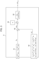
Claims (13)

  1. A power conversion device comprising: a processor that computes a first power from a voltage and a current of a magnet motor, computes a second power from electric circuit parameters of the magnet motor, steady components and transient components of the current of the magnet motor, and a frequency estimation value of the magnet motor, estimates a phase deviation indicating a deviation between a phase of control and a phase of a magnetic flux of the magnet motor such that the first power follows the second power, and computes the frequency estimation value from an estimation value of the phase deviation.
  2. The power conversion device according to claim 1,
    wherein the first power and the second power are reactive powers.
  3. The power conversion device according to claim 1,
    wherein the first power and the second power are active powers.
  4. The power conversion device according to claim 2,
    wherein the processor
    computes the first power from a difference between products of voltage command values and current detection values of different components of a d axis as a magnetic flux axis of the magnet motor and a q axis as a torque axis of the magnet motor, and
    computes the second power from the electric circuit parameters, steady components and transient components of current detection values or current command values of the d axis and the q axis, and the frequency estimation value.
  5. The power conversion device according to claim 2,
    wherein the processor
    computes the first power from a product of a voltage amplitude value of one phase of three-phase AC, a current amplitude value of the phase, and a sine signal of a phase difference between a voltage command value and a current detection value of the phase, and
    computes the second power from the electric circuit parameters, steady components and transient components of current detection values or current command values of a d axis and a q axis, and the frequency estimation value.
  6. The power conversion device according to claim 3,
    wherein the processor
    computes the first power from a sum of products of voltage command values and current detection values of a same component of a d axis as a magnetic flux axis of the magnet motor and a q axis as a torque axis of the magnet motor, and
    computes the second power from the electric circuit parameters, steady components and transient components of current detection values or current command values of the d axis and the q axis, and the frequency estimation value.
  7. The power conversion device according to claim 3,
    wherein the processor
    computes the first power from a product of a voltage amplitude value of one phase of three-phase AC, a current amplitude value of the phase, and a cosine signal of a phase difference between a voltage command value and a current detection value of the phase, and
    computes the second power from the electric circuit parameters, steady components and transient components of current detection values or current command values of a d axis and a q axis, and the frequency estimation value.
  8. The power conversion device according to claim 1,
    wherein the processor
    computes the estimation value of the phase deviation by performing proportional control and integral control such that a power deviation indicating a deviation between the first power and the second power is zero.
  9. The power conversion device according to claim 8,
    wherein the processor
    computes the estimation value of the phase deviation by performing the proportional control and the integral control such that the power deviation between reactive powers is zero in a low speed range where a frequency command value is less than a threshold value, and
    computes the estimation value of the phase deviation by performing the proportional control and the integral control such that the power deviation between active powers is zero in a medium/high speed range where the frequency command value is equal to or larger than the threshold value.
  10. The power conversion device according to claim 8,
    wherein the processor
    computes the estimation value of the phase deviation by performing the proportional control and the integral control such that the power deviation between reactive powers is zero in a low speed range where a frequency command value is less than a threshold value, and
    computes the estimation value of the phase deviation by an extended induced voltage method in a medium/high speed range where the frequency command value is equal to or larger than the threshold value.
  11. The power conversion device according to claim 9, the device comprising:
    a storage device that stores the threshold value and a control response used for the proportional control or the integral control;
    an input device that sets the threshold value and the control response; or
    a communication device that communicates with an external device for setting the threshold value and the control response.
  12. The power conversion device according to claim 11,
    wherein the processor
    transmits voltage command values, current detection values, and an estimation value of the phase deviation to a controller of a higher device via the communication device,
    receives inductances of a d axis and a q axis of the magnet motor or an induced voltage coefficient, the inductances and the induced voltage coefficient being analyzed on a basis of the voltage command values, the current detection values, and the estimation value of the phase deviation, from the controller of the higher device via the communication device, and
    updates the electric circuit parameters with the received values.
  13. The power conversion device according to claim 1,
    wherein the processor
    computes the second power from the electrical circuit parameters, steady components and transient components of current detection values or current command values of a d axis and a q axis, and the frequency estimation value.
EP24182977.9A 2023-11-08 2024-06-19 Power conversion device Pending EP4554081A1 (en)

Applications Claiming Priority (1)

Application Number Priority Date Filing Date Title
JP2023190952A JP2025078406A (en) 2023-11-08 2023-11-08 Power Conversion Equipment

Publications (1)

Publication Number Publication Date
EP4554081A1 true EP4554081A1 (en) 2025-05-14

Family

ID=91616732

Family Applications (1)

Application Number Title Priority Date Filing Date
EP24182977.9A Pending EP4554081A1 (en) 2023-11-08 2024-06-19 Power conversion device

Country Status (4)

Country Link
US (1) US20250147563A1 (en)
EP (1) EP4554081A1 (en)
JP (1) JP2025078406A (en)
CN (1) CN119966296A (en)

Families Citing this family (1)

* Cited by examiner, † Cited by third party
Publication number Priority date Publication date Assignee Title
US12539574B2 (en) * 2023-10-25 2026-02-03 Fanuc Corporation Sensorless chatter detection

Citations (4)

* Cited by examiner, † Cited by third party
Publication number Priority date Publication date Assignee Title
EP1681762A2 (en) * 2005-01-13 2006-07-19 Hitachi, Ltd. Synchronous motor driving system and method
US20070126391A1 (en) * 2005-12-02 2007-06-07 Kazuaki Tobari Vector controller for a permanent magnet synchronous motor, inverter module, and permanent magnet synchronous motor constant display system
US20210328537A1 (en) * 2017-02-28 2021-10-21 Hitachi Industrial Equipment Systems Co., Ltd. AC Electric Motor Control Device
CN116830450A (en) * 2021-05-14 2023-09-29 株式会社日立产机系统 power conversion device

Family Cites Families (3)

* Cited by examiner, † Cited by third party
Publication number Priority date Publication date Assignee Title
JP7358277B2 (en) * 2020-03-03 2023-10-10 株式会社東芝 Drive device, drive system, and electric motor drive method
US11088643B1 (en) * 2020-03-03 2021-08-10 Infineon Technologies Austria Ag Demagnetization sensing for permanent magnet synchronous motor drive
GB2604135B (en) * 2021-02-25 2023-06-14 Dyson Technology Ltd A method of controlling a brushless permanent magnet motor

Patent Citations (6)

* Cited by examiner, † Cited by third party
Publication number Priority date Publication date Assignee Title
EP1681762A2 (en) * 2005-01-13 2006-07-19 Hitachi, Ltd. Synchronous motor driving system and method
JP4402600B2 (en) 2005-01-13 2010-01-20 株式会社日立製作所 Synchronous motor drive system and synchronous motor drive method
US20070126391A1 (en) * 2005-12-02 2007-06-07 Kazuaki Tobari Vector controller for a permanent magnet synchronous motor, inverter module, and permanent magnet synchronous motor constant display system
US20210328537A1 (en) * 2017-02-28 2021-10-21 Hitachi Industrial Equipment Systems Co., Ltd. AC Electric Motor Control Device
CN116830450A (en) * 2021-05-14 2023-09-29 株式会社日立产机系统 power conversion device
US20240097589A1 (en) * 2021-05-14 2024-03-21 Hitachi Industrial Equipment Systems Co., Ltd. Power Conversion Device

Also Published As

Publication number Publication date
CN119966296A (en) 2025-05-09
JP2025078406A (en) 2025-05-20
US20250147563A1 (en) 2025-05-08

Similar Documents

Publication Publication Date Title
EP1748550B1 (en) Synchronous machine controller
CN104335476B (en) Motor control device and motor control method
US9991829B2 (en) Direct-axis current protection method and device for permanent magnet synchronous motor drive system
EP3267577B1 (en) Power conversion device and method for controlling same
Lee et al. MTPA control method for MIDP SPMSM drive system using angle difference controller and P&O algorithm
CN103051269A (en) Synchronous machine control apparatus
EP4340211B1 (en) Power conversion device
EP4213370A1 (en) Power conversion device
US20160261218A1 (en) Driving apparatus for electric motor
US20250147563A1 (en) Power conversion device
Dinh et al. Improved scalar control based on slip compensation from virtual speeds in three-phase induction motor drives
US7145311B2 (en) Vector control device of winding field type synchronous machine
EP4075665B1 (en) Power converter
EP4625808A1 (en) Power conversion device
JPH06225574A (en) Method and apparatus for controlling motor
EP4704330A1 (en) Power conversion device
JP2020058231A (en) Power converter control method and power converter
WO2025182128A1 (en) Motor control device and motor control system
EP4510443A1 (en) Power conversion device
CN107148744B (en) Power conversion device and control method for power conversion device
JP5456873B1 (en) Synchronous machine controller
EP4625809A1 (en) Power conversion device and motor control system
JP5104217B2 (en) Control device for permanent magnet type synchronous motor
JP5228629B2 (en) AC motor inverter device and motor current control method thereof

Legal Events

Date Code Title Description
PUAI Public reference made under article 153(3) epc to a published international application that has entered the european phase

Free format text: ORIGINAL CODE: 0009012

STAA Information on the status of an ep patent application or granted ep patent

Free format text: STATUS: REQUEST FOR EXAMINATION WAS MADE

17P Request for examination filed

Effective date: 20240816

AK Designated contracting states

Kind code of ref document: A1

Designated state(s): AL AT BE BG CH CY CZ DE DK EE ES FI FR GB GR HR HU IE IS IT LI LT LU LV MC ME MK MT NL NO PL PT RO RS SE SI SK SM TR

GRAP Despatch of communication of intention to grant a patent

Free format text: ORIGINAL CODE: EPIDOSNIGR1

STAA Information on the status of an ep patent application or granted ep patent

Free format text: STATUS: GRANT OF PATENT IS INTENDED

INTG Intention to grant announced

Effective date: 20260217