EP4554054A1 - Motor rotor and method for manufacturing motor rotor - Google Patents
Motor rotor and method for manufacturing motor rotor Download PDFInfo
- Publication number
- EP4554054A1 EP4554054A1 EP23854940.6A EP23854940A EP4554054A1 EP 4554054 A1 EP4554054 A1 EP 4554054A1 EP 23854940 A EP23854940 A EP 23854940A EP 4554054 A1 EP4554054 A1 EP 4554054A1
- Authority
- EP
- European Patent Office
- Prior art keywords
- magnet
- holding tube
- shaft
- circumferential surface
- diameter
- Prior art date
- Legal status (The legal status is an assumption and is not a legal conclusion. Google has not performed a legal analysis and makes no representation as to the accuracy of the status listed.)
- Pending
Links
Images




Classifications
-
- H—ELECTRICITY
- H02—GENERATION; CONVERSION OR DISTRIBUTION OF ELECTRIC POWER
- H02K—DYNAMO-ELECTRIC MACHINES
- H02K1/00—Details of the magnetic circuit
- H02K1/06—Details of the magnetic circuit characterised by the shape, form or construction
- H02K1/22—Rotating parts of the magnetic circuit
- H02K1/28—Means for mounting or fastening rotating magnetic parts on to, or to, the rotor structures
-
- H—ELECTRICITY
- H02—GENERATION; CONVERSION OR DISTRIBUTION OF ELECTRIC POWER
- H02K—DYNAMO-ELECTRIC MACHINES
- H02K1/00—Details of the magnetic circuit
- H02K1/06—Details of the magnetic circuit characterised by the shape, form or construction
- H02K1/22—Rotating parts of the magnetic circuit
- H02K1/27—Rotor cores with permanent magnets
- H02K1/2706—Inner rotors
- H02K1/272—Inner rotors the magnetisation axis of the magnets being perpendicular to the rotor axis
- H02K1/2726—Inner rotors the magnetisation axis of the magnets being perpendicular to the rotor axis the rotor consisting of a single magnet or two or more axially juxtaposed single magnets
- H02K1/2733—Annular magnets
-
- H—ELECTRICITY
- H02—GENERATION; CONVERSION OR DISTRIBUTION OF ELECTRIC POWER
- H02K—DYNAMO-ELECTRIC MACHINES
- H02K15/00—Processes or apparatus specially adapted for manufacturing, assembling, maintaining or repairing of dynamo-electric machines
- H02K15/02—Processes or apparatus specially adapted for manufacturing, assembling, maintaining or repairing of dynamo-electric machines of stator or rotor bodies
- H02K15/028—Fastening stator or rotor bodies to casings, supports, shafts or hubs
-
- H—ELECTRICITY
- H02—GENERATION; CONVERSION OR DISTRIBUTION OF ELECTRIC POWER
- H02K—DYNAMO-ELECTRIC MACHINES
- H02K15/00—Processes or apparatus specially adapted for manufacturing, assembling, maintaining or repairing of dynamo-electric machines
- H02K15/02—Processes or apparatus specially adapted for manufacturing, assembling, maintaining or repairing of dynamo-electric machines of stator or rotor bodies
- H02K15/03—Processes or apparatus specially adapted for manufacturing, assembling, maintaining or repairing of dynamo-electric machines of stator or rotor bodies having permanent magnets
- H02K15/035—Processes or apparatus specially adapted for manufacturing, assembling, maintaining or repairing of dynamo-electric machines of stator or rotor bodies having permanent magnets on the rotor
-
- H—ELECTRICITY
- H02—GENERATION; CONVERSION OR DISTRIBUTION OF ELECTRIC POWER
- H02K—DYNAMO-ELECTRIC MACHINES
- H02K2213/00—Specific aspects, not otherwise provided for and not covered by codes H02K2201/00 - H02K2211/00
- H02K2213/03—Machines characterised by numerical values, ranges, mathematical expressions or similar information
Definitions
- the present disclosure relates to a motor rotor and a method for manufacturing the motor rotor.
- a holding tube is fitted onto the outside of the magnet so that the magnet can withstand centrifugal force.
- the holding tube is fixed to a shaft by being shrink fitted onto an outer circumferential surface of a sleeve provided adjacent to the magnet.
- Patent Literature 1 Japanese Patent No. 5359062
- the magnet when the holding tube in a high-temperature state abuts on the magnet in the shrink fitting of the holding tube, the magnet may be locally demagnetized at the abutting portion. Therefore, in the technical field, there is a demand for a motor rotor capable of suppressing local demagnetization of a magnet of a shaft portion when a holding tube is attached to the shaft portion by shrink fitting, and a method for manufacturing the motor rotor.
- a motor rotor includes a shaft portion having a magnet, and a holding tube fitted onto an outer circumferential surface of the shaft portion.
- the shaft portion includes the magnet and a large-diameter portion having an outer diameter larger than an outer diameter of the magnet.
- the large-diameter portion is provided adjacent to the magnet in an extending direction of the shaft portion.
- An inner circumferential surface of the holding tube abuts on an outer circumferential surface of the magnet and an outer circumferential surface of the large-diameter portion.
- the holding tube when the holding tube is attached to the shaft portion by shrink fitting, it is possible to suppress local demagnetization of the magnet of the shaft portion.
- a motor rotor includes a shaft portion having a magnet, and a holding tube fitted onto an outer circumferential surface of the shaft portion.
- the shaft portion includes the magnet and a large-diameter portion having an outer diameter larger than an outer diameter of the magnet.
- the large-diameter portion is provided adjacent to the magnet in an extending direction of the shaft portion.
- An inner circumferential surface of the holding tube abuts on an outer circumferential surface of the magnet and an outer circumferential surface of the large-diameter portion.
- the outer diameter of the large-diameter portion is larger than the outer diameter of the magnet. Therefore, when the shaft portion is inserted inside the holding tube in order to attach the holding tube by shrink fitting, it is possible to suppress direct abutting of the inner circumferential surface of the holding tube on the magnet. As a result, it is possible to suppress direct abutting of the holding tube in a high-temperature state on the magnet in an initial stage of a cooling step of the holding tube in shrink fitting. Therefore, this motor rotor can suppress local demagnetization of the magnet of the shaft portion when the holding tube is attached to the shaft portion by shrink fitting.
- the shaft portion may further include a shaft having a rod shape.
- the large-diameter portion may have a tubular shape.
- the large-diameter portion may be attached to the shaft such that the shaft passes through the large-diameter portion.
- the magnet may have a tubular shape.
- the shaft may pass through the magnet. In this case, even when the holding tube is attached by shrink fitting to the shaft portion having such a configuration, the motor rotor can suppress local demagnetization of the magnet.
- the magnet may include a plurality of magnet bodies arranged side by side along a circumferential direction of the shaft or a plurality of magnet bodies arranged side by side along an extending direction of the shaft.
- the magnet including the plurality of magnet bodies can be used in the motor rotor, and restrictions on the shape of the magnet can be suppressed.
- the shaft portion may further include a shaft having a rod shape.
- the large-diameter portion may have a columnar shape.
- the large-diameter portion may be attached to the shaft so as to be coaxial with the shaft.
- the magnet may have a columnar shape.
- the magnet may be disposed coaxially with the shaft.
- the shaft and the large-diameter portion may be integrally formed.
- the number of components can be reduced.
- a step of attaching the large-diameter portion to the shaft can be omitted.
- An outer diameter of a portion surrounding the large-diameter portion in the holding tube described above may be larger than an outer diameter of a portion surrounding the magnet in the holding tube.
- the method for manufacturing the motor rotor includes: a step of preparing the shaft portion including the magnet and a large-diameter portion provided adjacent to the magnet in an extending direction of the shaft portion and having an outer diameter larger than an outer diameter of the magnet; a step of heating the holding tube to increase an inner diameter of the holding tube as compared with the inner diameter before heating; a step of inserting the shaft portion into the heated holding tube such that an outer circumferential surface of the large-diameter portion and an outer circumferential surface of the magnet face an inner circumferential surface of the holding tube; and a step of reducing the holding tube by cooling the holding tube while the shaft portion is inserted into the holding tube, thereby causing the inner circumferential surface of the holding tube to abut on the outer circumferential surface of the large-dia
- the shaft portion including the large-diameter portion having the outer diameter larger than the outer diameter of the magnet is prepared. Therefore, when the shaft portion is inserted inside the holding tube in order to attach the holding tube by shrink fitting, it is possible to suppress direct abutting of the inner circumferential surface of the holding tube on the magnet. As a result, it is possible to suppress direct abutting of the holding tube in a high-temperature state on the magnet in an initial stage of a cooling step of the holding tube in shrink fitting. Therefore, this method for manufacturing the motor rotor can suppress local demagnetization of the magnet of the shaft portion when the holding tube is attached to the shaft portion by shrink fitting.
- a motor rotor 1 according to the first embodiment illustrated in FIG. 1 constitutes, for example, a rotor of an electric motor.
- the type of a motor in which the motor rotor 1 is used is not limited.
- the motor rotor 1 includes a shaft portion 10 having a magnet 12, and a holding tube 20 fitted onto an outer circumferential surface (an outer circumferential surface 12a of the magnet 12 and outer circumferential surfaces 13a and 14a of sleeves 13 and 14) of the shaft portion 10.
- the holding tube 20 is attached to the outer circumferential surface of the shaft portion 10 by shrink fitting.
- the shaft portion 10 includes a shaft 11, the magnet 12, the sleeve (large-diameter portion) 13, and the sleeve (large-diameter portion) 14.
- the shaft 11 has a rod shape.
- the shaft 11 has a cylindrical shape.
- the magnet 12 has a tubular shape (cylindrical shape in the present embodiment).
- the shaft 11 passes through the magnet 12.
- the magnet 12 may be attached to an outer circumferential surface 11a of the shaft 11 by bonding an inner circumferential surface 12b of the magnet 12 to the outer circumferential surface 11a of the shaft 11 with an adhesive.
- the sleeves 13 and 14 are provided adjacent to the magnet 12 in an extending direction of the shaft portion 10.
- the sleeve 13 is disposed on one end side of the magnet 12 in the extending direction of the shaft portion 10.
- the sleeve 14 is disposed on the other end side of the magnet 12 in the extending direction of the shaft portion 10. That is, the magnet 12 is disposed between the sleeve 13 and the sleeve 14 in the extending direction of the shaft portion 10.
- the word "adjacent" does not indicate only a state in which no intervening object is included between the sleeves 13 and 14 and the magnet 12 as in the present embodiment.
- the word “adjacent” may include a state in which there is a thin intervening object such as an adhesive or a cushioning material between the sleeves 13 and 14 and the magnet 12.
- Each of the sleeves 13 and 14 has a tubular shape (cylindrical shape in the present embodiment).
- the sleeves 13 and 14 are attached to the shaft 11 such that the shaft 11 passes through the sleeves.
- the sleeve 13 may be attached to the shaft 11 by, for example, fitting an inner circumferential surface 13b of the sleeve 13 onto the outer circumferential surface 11a of the shaft 11 by shrink fitting.
- the sleeve 14 may be attached to the shaft 11 by, for example, fitting an inner circumferential surface 14b of the sleeve 14 onto the outer circumferential surface 11a of the shaft 11 by shrink fitting.
- the sleeves 13 and 14 may be attached to the outer circumferential surface 11a of the shaft 11 with screws or the like.
- An outer diameter A1 of the sleeve 13 is larger than an outer diameter A2 of the magnet 12.
- the sleeve 14 has the same shape as the sleeve 13. Therefore, an outer diameter A1 of the sleeve 14 is larger than the outer diameter A2 of the magnet 12.
- This normal room temperature state can be said to be a state in which a motor on which the motor rotor 1 is mounted is in a non-operating state and there is no temperature rise due to the operation.
- the normal room temperature state can be said to be a temperature state of the outside air temperature under the use environment of the motor on which the motor rotor 1 is mounted.
- the holding tube 20 has a cylindrical shape.
- the holding tube 20 is made of a material that expands when heated (for example, a metal material).
- An inner circumferential surface 20b of the holding tube 20 abuts on the outer circumferential surface 12a of the magnet 12, the outer circumferential surface 13a of the sleeve 13, and the outer circumferential surface 14a of the sleeve 14.
- the holding tube 20 is fitted onto the outer circumferential surface of the shaft portion 10 by shrink fitting. Therefore, the inner circumferential surface 20b of the holding tube 20 tightens the outer circumferential surface 12a of the magnet 12, the outer circumferential surface 13a of the sleeve 13, and the outer circumferential surface 14a of the sleeve 14.
- an inner diameter of a portion surrounding the magnet 12 is smaller than an inner diameter of a portion surrounding the sleeve 13 and an inner diameter of a portion surrounding the sleeve 14.
- an outer diameter of the portion surrounding the magnet 12 is smaller than an outer diameter of the portion surrounding the sleeve 13 and an outer diameter of the portion surrounding the sleeve 14.
- the holding tube 20 is integrally rotatable with the shaft portion 10 by tightening the outer circumferential surface (the outer circumferential surface 12a of the magnet 12 and the outer circumferential surfaces 13a and 14a of the sleeves 13 and 14) of the shaft portion 10.
- the shaft portion 10 is first prepared (S101: step of preparing the shaft portion).
- the shaft portion 10 prepared in this step is the shaft portion 10 including the magnet 12 and the sleeves 13 and 14 provided adjacent to the magnet 12 in the extending direction of the shaft portion 10 and having an outer diameter larger than the outer diameter of the magnet 12.
- the holding tube 20 is heated to increase the inner diameter of the holding tube 20 as compared with the inner diameter before heating (S102: step of heating the holding tube to increase the inner diameter).
- the shaft portion 10 is inserted into the heated holding tube 20 such that the outer circumferential surface 12a of the magnet 12, the outer circumferential surface 13a of the sleeve 13, and the outer circumferential surface 14a of the sleeve 14 face the inner circumferential surface 20b of the holding tube 20 (S103: step of inserting the shaft portion).
- the outer circumferential surface of the shaft portion 10 abuts on the inner circumferential surface 20b of the holding tube 20 in a high-temperature state.
- the outer diameters of the sleeves 13 and 14 are larger than the outer diameter of the magnet 12. Therefore, as illustrated in FIGS. 4(a) and 4(b) , the outer circumferential surface 13a of the sleeve 13 and the outer circumferential surface 14a of the sleeve 14 come into line contact with the inner circumferential surface 20b of the holding tube 20.
- the outer circumferential surface 12a of the magnet 12 does not abut on the inner circumferential surface 20b of the holding tube 20. As a result, it is possible to suppress direct abutting of the holding tube 20 in the high-temperature state on the magnet 12.
- the diameter (inner diameter and outer diameter) of the holding tube 20 is reduced by cooling the holding tube 20 in a state where the shaft portion 10 is inserted into the holding tube 20.
- the inner circumferential surface 20b of the holding tube 20 is caused to abut on the outer circumferential surface 12a of the magnet 12, the outer circumferential surface 13a of the sleeve 13, and the outer circumferential surface 14a of the sleeve 14 (S104: step of cooling the holding tube to cause the inner circumferential surface of the holding tube to abut on the outer circumferential surfaces of the magnet and the sleeves).
- the diameter of a portion of the holding tube 20 facing the outer circumferential surface 12a of the magnet 12 is further reduced.
- the inner circumferential surface 20b of the holding tube 20 also abuts on the outer circumferential surface 12a of the magnet 12. That is, the holding tube 20 abuts on the magnet 12 in a state where the temperature of the holding tube 20 at the end of the cooling step of the holding tube 20 is lowered.
- the shaft portion 10 and the holding tube 20 are aligned, the inner circumferential surface 20b of the holding tube 20 can uniformly abut on the entire outer circumferential surface 12a of the magnet 12.
- the holding tube 20, the magnet 12, the sleeve 13, and the sleeve 14 are fitted to each other, and the holding tube 20 is fitted to the shaft portion 10.
- the holding tube 20 is shrink fitted onto the outer circumferential surface of the shaft portion 10.
- the shaft portion 10 in which the outer diameters of the sleeves 13 and 14 are larger than the outer diameter of the magnet 12 is used. Therefore, when the shaft portion 10 is inserted inside the holding tube 20 in order to attach the holding tube 20 by shrink fitting, it is possible to suppress direct abutting of the inner circumferential surface 20b of the holding tube 20 on the magnet 12. As a result, it is possible to suppress direct abutting of the holding tube 20 in the high-temperature state on the magnet 12 in the initial stage of the cooling step of the holding tube 20 in shrink fitting. Therefore, the motor rotor 1 can suppress local demagnetization of the magnet 12 of the shaft portion 10 when the holding tube 20 is attached to the shaft portion 10 by shrink fitting.
- the shaft portion 10 includes the shaft 11 having a rod shape, the magnet 12 provided around the shaft 11, and the sleeves 13 and 14. In this case, even when the holding tube 20 is attached by shrink fitting to the shaft portion 10 having such a configuration, the motor rotor 1 can suppress local demagnetization of the magnet 12.
- the outer diameters of the portions surrounding the sleeves 13 and 14 in the holding tube 20 are larger than the outer diameter of the portion surrounding the magnet 12. That is, the outer circumferential surface 20a of the holding tube 20 has a shape along the outer diameters of the magnet 12 and the sleeves 13 and 14.
- the motor rotor 1 can sufficiently pressurize not only the sleeves 13 and 14 but also the portion of the magnet 12 smaller than the outer diameters of the sleeves 13 and 14 with the holding tube 20 to hold the magnet 12.
- the magnet 12 described above is not limited to one lump of magnet, and may include a plurality of magnet bodies.
- the magnet 12 may include a plurality of magnet bodies arranged side by side along a circumferential direction of the shaft 11.
- the magnet 12 may include a plurality of magnet bodies arranged side by side along the extending direction of the shaft 11.
- the magnet 12 including the plurality of magnet bodies can be used in the motor rotor 1, and restrictions on the shape of the magnet 12 can be suppressed.
- the sleeves 13 and 14 described above may be formed integrally with the shaft 11. In this case, in the motor rotor 1, the number of components can be reduced. In addition, in the motor rotor 1, a step of attaching the sleeves 13 and 14 to the shaft 11 can be omitted.
- a motor rotor 1A according to the second embodiment includes a shaft portion 10A having a different configuration instead of the shaft portion 10 according to the first embodiment.
- a holding tube 20 is attached to an outer circumferential surface (an outer circumferential surface 15a of a magnet 15 and outer circumferential surfaces 17a and 19a of large-diameter portions 17 and 19) of the shaft portion 10A by shrink fitting.
- the shaft portion 10A includes the magnet 15, a shaft 16, the large-diameter portion 17, a shaft 18, and the large-diameter portion 19.
- the magnet 15 has a columnar shape. That is, the magnet 15 is a solid magnet unlike the magnet 12 of the first embodiment.
- the shafts 16 and 18 each have a rod shape. In the present embodiment, the shafts 16 and 18 have a columnar shape.
- the large-diameter portions 17 and 19 have a columnar shape (a columnar shape having a short length in an extending direction of the shaft portion 10A).
- the large-diameter portion 17, the magnet 15, the large-diameter portion 19, and the shaft 18 are disposed so as to be coaxial with the shaft 16. That is, the shaft 16, the large-diameter portion 17, the magnet 15, the large-diameter portion 19, and the shaft 18 are disposed coaxially with each other. In addition, the shaft 16, the large-diameter portion 17, the magnet 15, the large-diameter portion 19, and the shaft 18 are connected (attached) to each other in this arrangement order.
- the large-diameter portions 17 and 19 are provided adjacent to the magnet 15 in the extending direction of the shaft portion 10A.
- the large-diameter portion 17 is disposed on one end side of the magnet 15 in the extending direction of the shaft portion 10A.
- the large-diameter portion 19 is disposed on the other end side of the magnet 15 in the extending direction of the shaft portion 10A.
- An outer diameter B1 of the large-diameter portion 17 is larger than an outer diameter B2 of the magnet 15.
- the large-diameter portion 19 has the same shape as the large-diameter portion 17. Therefore, an outer diameter B1 of the large-diameter portion 19 is larger than the outer diameter B2 of the magnet 15.
- This normal room temperature state can be said to be a state in which a motor on which the motor rotor 1A is mounted is in a non-operating state and there is no temperature rise due to the operation.
- the normal room temperature state can be said to be a temperature state of the outside air temperature under the use environment of the motor on which the motor rotor 1A is mounted.
- the holding tube 20 has a cylindrical shape.
- the holding tube 20 is made of a material that expands when heated (for example, a metal material).
- An inner circumferential surface 20b of the holding tube 20 abuts on the outer circumferential surface 15a of the magnet 15, the outer circumferential surface 17a of the large-diameter portion 17, and the outer circumferential surface 19a of the large-diameter portion 19. Note that as described above, the holding tube 20 is fitted onto the outer circumferential surface of the shaft portion 10A by shrink fitting.
- the inner circumferential surface 20b of the holding tube 20 tightens the outer circumferential surface 15a of the magnet 15, the outer circumferential surface 17a of the large-diameter portion 17, and the outer circumferential surface 19a of the large-diameter portion 19.
- an inner diameter of a portion surrounding the magnet 15 is smaller than an inner diameter of a portion surrounding the large-diameter portion 17 and an inner diameter of a portion surrounding the large-diameter portion 19.
- an outer diameter of the portion surrounding the magnet 15 is smaller than an outer diameter of the portion surrounding the large-diameter portion 17 and an outer diameter of the portion surrounding the large-diameter portion 19.
- the holding tube 20 is integrally rotatable with the shaft portion 10A by tightening the outer circumferential surface (the outer circumferential surface 15a of the magnet 15 and the outer circumferential surfaces 17a and 19a of the large-diameter portions 17 and 19) of the shaft portion 10A.
- the shaft portion 10A is first prepared (S101: step of preparing the shaft portion).
- the shaft portion 10A prepared in this step is the shaft portion 10A including the magnet 15 and the large-diameter portions 17 and 19 provided adjacent to the magnet 15 in the extending direction of the shaft portion 10A and having an outer diameter larger than the outer diameter of the magnet 15.
- the holding tube 20 is heated to increase the inner diameter of the holding tube 20 as compared with the inner diameter before heating (S102: step of heating the holding tube to increase the inner diameter).
- the shaft portion 10A is inserted into the heated holding tube 20 such that the outer circumferential surface 15a of the magnet 15, the outer circumferential surface 17a of the large-diameter portion 17, and the outer circumferential surface 19a of the large-diameter portion 19 face the inner circumferential surface 20b of the holding tube 20 (S103: step of inserting the shaft portion).
- the diameter (inner diameter and outer diameter) of the holding tube 20 is reduced by cooling the holding tube 20 in a state where the shaft portion 10A is inserted into the holding tube 20. Then, as illustrated in FIG. 6 , the inner circumferential surface 20b of the holding tube 20 is caused to abut on the outer circumferential surface 15a of the magnet 15, the outer circumferential surface 17a of the large-diameter portion 17, and the outer circumferential surface 19a of the large-diameter portion 19 (S104: step of cooling the holding tube to cause the inner circumferential surface of the holding tube to abut on the outer circumferential surfaces of the magnet and the large-diameter portions).
- step S104 alignment of the shaft portion 10A with the holding tube 20 is performed as in the first embodiment.
- the magnet 15 and the holding tube 20 in the high-temperature state do not abut on each other.
- the holding tube 20 abuts on the magnet 15 in a state where the temperature of the holding tube 20 at the end of the cooling step of the holding tube 20 is lowered.
- the shaft portion 10A in which the outer diameters of the large-diameter portions 17 and 19 are larger than the outer diameter of the magnet 15 is used. Therefore, when the shaft portion 10A is inserted inside the holding tube 20 in order to attach the holding tube 20 by shrink fitting, it is possible to suppress abutting of the inner circumferential surface 20b of the holding tube 20 on the magnet 15. As a result, it is possible to suppress direct abutting of the holding tube 20 in the high-temperature state on the magnet 15 in the initial stage of the cooling step of the holding tube 20 in shrink fitting. Therefore, the motor rotor 1A can suppress local demagnetization of the magnet 15 of the shaft portion 10A when the holding tube 20 is attached to the shaft portion 10A by shrink fitting.
- the shaft 16 In the shaft portion 10A, the shaft 16, the large-diameter portion 17, the magnet 15, the large-diameter portion 19, and the shaft 18 are disposed coaxially with each other and connected to each other.
- the magnet 15 is a solid magnet. In this case, even when the holding tube 20 is attached by shrink fitting to the shaft portion 10A having such a configuration, the motor rotor 1A can suppress local demagnetization of the magnet 15.
- the large-diameter portion 17 may be formed integrally with the shaft 16.
- the large-diameter portion 19 may be formed integrally with the shaft 18.
- the number of components can be reduced.
- a step of attaching the large-diameter portion 17 to the shaft 16 and a step of attaching the large-diameter portion 19 to the shaft 18 can be omitted.
- the shaft portion 10 according to the first embodiment may be configured to include only one of the sleeves 13 and 14.
- the shaft portion 10A according to the second embodiment may be configured to include only one of the large-diameter portions 17 and 19. Even in these cases, the shaft portions 10 and 10A can suppress local demagnetization of the magnets 12 and 15 when the holding tube 20 is attached by shrink fitting.
- FIG. 8 illustrates temperature changes of the surface of the magnet 12 due to a difference in the ratio (outer diameter ratio) of the outer diameter of the magnet 12 to the outer diameters of the sleeves 13 and 14.
- the outer diameter ratio means that as the outer diameter ratio decreases, the outer diameter of the magnet 12 decreases with respect to the outer diameters of the sleeves 13 and 14.
- the temperature of the surface of the magnet 12 at each outer diameter ratio is illustrated using a temperature ratio in a case where the temperature at an outer diameter ratio of 100.0% is 100% and the temperature at 0°C is 0%. Note that when the outer diameter ratio is 100.0%, the temperature of the surface of the magnet 12 reaches the surface temperature of the holding tube 20 almost simultaneously with the attachment of the holding tube 20.
- the temperature ratio was about 90% immediately after attaching the holding tube 20, and increased to about 95% or more after a lapse of several seconds.
- the temperature ratio was less than about 65% immediately after attachment of the holding tube 20, the temperature ratio was less than 80% even upon a lapse of several seconds, and the temperature ratio was less than 90% even upon a lapse of 15 seconds.
- the temperature rise of the magnet 12 can be greatly suppressed, and local demagnetization of the magnet 12 of the shaft portion 10 can be suppressed.
- the temperature change was analyzed using the motor rotor 1 according to the first embodiment, but it is obvious that local demagnetization of the magnet 15 of the shaft portion 10A can be suppressed with the same configuration (outer diameter ratio) also in the motor rotor 1A according to the second embodiment.
- the present disclosure includes the following configurations.
- a motor rotor of the present disclosure is
- the motor rotor of the present disclosure may be "The motor rotor according to [1], in which
- the motor rotor of the present disclosure may be "The motor rotor according to [2], in which the magnet includes a plurality of magnet bodies arranged side by side along a circumferential direction of the shaft or a plurality of magnet bodies arranged side by side along an extending direction of the shaft.”
- the motor rotor of the present disclosure may be "The motor rotor according to [1], in which
- the motor rotor of the present disclosure may be "The motor rotor according to any one of [1] to [4], in which the shaft and the large-diameter portion are integrally formed.”
- the motor rotor of the present disclosure may be "The motor rotor according to any one of [1] to [5], in which an outer diameter of a portion surrounding the large-diameter portion in the holding tube is larger than an outer diameter of a portion surrounding the magnet in the holding tube.”
- a method for manufacturing a motor rotor of the present disclosure is "A method for manufacturing a motor rotor including a shaft portion and a holding tube, the shaft portion having a magnet, the holding tube being shrink fitted onto an outer circumferential surface of the shaft portion, the method comprising:
Landscapes
- Engineering & Computer Science (AREA)
- Power Engineering (AREA)
- Manufacturing & Machinery (AREA)
- Permanent Field Magnets Of Synchronous Machinery (AREA)
- Iron Core Of Rotating Electric Machines (AREA)
- Manufacture Of Motors, Generators (AREA)
Abstract
A motor rotor includes a shaft portion having a magnet, and a holding tube fitted onto an outer circumferential surface of the shaft portion. The shaft portion includes the magnet and a large-diameter portion having an outer diameter larger than an outer diameter of the magnet. An inner circumferential surface of the holding tube abuts on an outer circumferential surface of the magnet and an outer circumferential surface of the large-diameter portion.
Description
- The present disclosure relates to a motor rotor and a method for manufacturing the motor rotor.
- In a motor rotor including a magnet, a holding tube is fitted onto the outside of the magnet so that the magnet can withstand centrifugal force. The holding tube is fixed to a shaft by being shrink fitted onto an outer circumferential surface of a sleeve provided adjacent to the magnet. Such a motor rotor including the holding tube is described in
Patent Literature 1, for example. - Patent Literature 1:
Japanese Patent No. 5359062 - In the motor rotor described above, when the holding tube in a high-temperature state abuts on the magnet in the shrink fitting of the holding tube, the magnet may be locally demagnetized at the abutting portion. Therefore, in the technical field, there is a demand for a motor rotor capable of suppressing local demagnetization of a magnet of a shaft portion when a holding tube is attached to the shaft portion by shrink fitting, and a method for manufacturing the motor rotor.
- A motor rotor according to one aspect of the present disclosure includes a shaft portion having a magnet, and a holding tube fitted onto an outer circumferential surface of the shaft portion. The shaft portion includes the magnet and a large-diameter portion having an outer diameter larger than an outer diameter of the magnet. The large-diameter portion is provided adjacent to the magnet in an extending direction of the shaft portion. An inner circumferential surface of the holding tube abuts on an outer circumferential surface of the magnet and an outer circumferential surface of the large-diameter portion.
- According to various aspects of the present disclosure, when the holding tube is attached to the shaft portion by shrink fitting, it is possible to suppress local demagnetization of the magnet of the shaft portion.
-
-
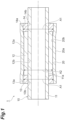
FIG. 1 is a cross-sectional view illustrating a motor rotor according to a first embodiment. -
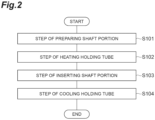
FIG. 2 is a flowchart illustrating a flow of a method for manufacturing the motor rotor. -
FIG. 3 is a cross-sectional view illustrating a state in which a shaft portion is to be inserted into a heated holding tube. -
FIG. 4(a) is a cross-sectional view illustrating a state in which the shaft portion is inserted into the heated holding tube.FIG. 4(b) is a cross-sectional view taken along line IVb-IVb inFIG. 4(a) . -
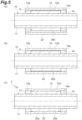
FIGS. 5(a) to 5(c) are cross-sectional views illustrating a state in which the holding tube is cooled to reduce the diameter thereof. -
FIG. 6 is a cross-sectional view illustrating a motor rotor according to a second embodiment. -
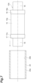
FIG. 7 is a cross-sectional view illustrating a state in which a shaft portion is to be inserted into a heated holding tube. -
FIG. 8 is a graph illustrating an analysis result of a temperature change of the magnet in a case where the heated holding tube is attached to the shaft portion. - A motor rotor according to one aspect of the present disclosure includes a shaft portion having a magnet, and a holding tube fitted onto an outer circumferential surface of the shaft portion. The shaft portion includes the magnet and a large-diameter portion having an outer diameter larger than an outer diameter of the magnet. The large-diameter portion is provided adjacent to the magnet in an extending direction of the shaft portion. An inner circumferential surface of the holding tube abuts on an outer circumferential surface of the magnet and an outer circumferential surface of the large-diameter portion.
- In this motor rotor, the outer diameter of the large-diameter portion is larger than the outer diameter of the magnet. Therefore, when the shaft portion is inserted inside the holding tube in order to attach the holding tube by shrink fitting, it is possible to suppress direct abutting of the inner circumferential surface of the holding tube on the magnet. As a result, it is possible to suppress direct abutting of the holding tube in a high-temperature state on the magnet in an initial stage of a cooling step of the holding tube in shrink fitting. Therefore, this motor rotor can suppress local demagnetization of the magnet of the shaft portion when the holding tube is attached to the shaft portion by shrink fitting.
- In the motor rotor described above, the shaft portion may further include a shaft having a rod shape. The large-diameter portion may have a tubular shape. The large-diameter portion may be attached to the shaft such that the shaft passes through the large-diameter portion. The magnet may have a tubular shape. The shaft may pass through the magnet. In this case, even when the holding tube is attached by shrink fitting to the shaft portion having such a configuration, the motor rotor can suppress local demagnetization of the magnet.
- In the motor rotor described above, the magnet may include a plurality of magnet bodies arranged side by side along a circumferential direction of the shaft or a plurality of magnet bodies arranged side by side along an extending direction of the shaft. In this case, the magnet including the plurality of magnet bodies can be used in the motor rotor, and restrictions on the shape of the magnet can be suppressed.
- In the motor rotor described above, the shaft portion may further include a shaft having a rod shape. The large-diameter portion may have a columnar shape. The large-diameter portion may be attached to the shaft so as to be coaxial with the shaft. The magnet may have a columnar shape. The magnet may be disposed coaxially with the shaft. In this case, in the motor rotor having a configuration including a solid magnet, it is possible to suppress local demagnetization of the magnet when the holding tube is attached by shrink fitting.
- In the motor rotor described above, the shaft and the large-diameter portion may be integrally formed. In this case, in the motor rotor, the number of components can be reduced. In addition, in this motor rotor, a step of attaching the large-diameter portion to the shaft can be omitted.
- An outer diameter of a portion surrounding the large-diameter portion in the holding tube described above may be larger than an outer diameter of a portion surrounding the magnet in the holding tube. As a result, in the motor rotor, not only the large-diameter portion but also the magnet smaller than the outer diameter of the large-diameter portion can be sufficiently pressurized by the holding tube to hold the magnet.
- Another aspect of the present disclosure is a method for manufacturing a motor rotor including a shaft portion and a holding tube, the shaft portion having a magnet, the holding tube being shrink fitted onto an outer circumferential surface of the shaft portion. The method for manufacturing the motor rotor includes: a step of preparing the shaft portion including the magnet and a large-diameter portion provided adjacent to the magnet in an extending direction of the shaft portion and having an outer diameter larger than an outer diameter of the magnet; a step of heating the holding tube to increase an inner diameter of the holding tube as compared with the inner diameter before heating; a step of inserting the shaft portion into the heated holding tube such that an outer circumferential surface of the large-diameter portion and an outer circumferential surface of the magnet face an inner circumferential surface of the holding tube; and a step of reducing the holding tube by cooling the holding tube while the shaft portion is inserted into the holding tube, thereby causing the inner circumferential surface of the holding tube to abut on the outer circumferential surface of the large-diameter portion and the outer circumferential surface of the magnet.
- In this method for manufacturing the motor rotor, the shaft portion including the large-diameter portion having the outer diameter larger than the outer diameter of the magnet is prepared. Therefore, when the shaft portion is inserted inside the holding tube in order to attach the holding tube by shrink fitting, it is possible to suppress direct abutting of the inner circumferential surface of the holding tube on the magnet. As a result, it is possible to suppress direct abutting of the holding tube in a high-temperature state on the magnet in an initial stage of a cooling step of the holding tube in shrink fitting. Therefore, this method for manufacturing the motor rotor can suppress local demagnetization of the magnet of the shaft portion when the holding tube is attached to the shaft portion by shrink fitting.
- Hereinafter, embodiments of the present disclosure will be described with reference to the drawings. Note that in the drawings, the same or corresponding elements are denoted by the same reference numerals, and redundant description will be omitted.
- First, a first embodiment of a motor rotor will be described. A
motor rotor 1 according to the first embodiment illustrated inFIG. 1 constitutes, for example, a rotor of an electric motor. The type of a motor in which themotor rotor 1 is used is not limited. Themotor rotor 1 includes ashaft portion 10 having amagnet 12, and a holdingtube 20 fitted onto an outer circumferential surface (an outercircumferential surface 12a of themagnet 12 and outercircumferential surfaces sleeves 13 and 14) of theshaft portion 10. In the present embodiment, the holdingtube 20 is attached to the outer circumferential surface of theshaft portion 10 by shrink fitting. - The
shaft portion 10 includes ashaft 11, themagnet 12, the sleeve (large-diameter portion) 13, and the sleeve (large-diameter portion) 14. Theshaft 11 has a rod shape. In the present embodiment, theshaft 11 has a cylindrical shape. Themagnet 12 has a tubular shape (cylindrical shape in the present embodiment). As themagnet 12, for example, various permanent magnets and the like are used. - The
shaft 11 passes through themagnet 12. For example, themagnet 12 may be attached to an outercircumferential surface 11a of theshaft 11 by bonding an innercircumferential surface 12b of themagnet 12 to the outercircumferential surface 11a of theshaft 11 with an adhesive. - The
sleeves magnet 12 in an extending direction of theshaft portion 10. In the present embodiment, thesleeve 13 is disposed on one end side of themagnet 12 in the extending direction of theshaft portion 10. Thesleeve 14 is disposed on the other end side of themagnet 12 in the extending direction of theshaft portion 10. That is, themagnet 12 is disposed between thesleeve 13 and thesleeve 14 in the extending direction of theshaft portion 10. Note that the word "adjacent" does not indicate only a state in which no intervening object is included between thesleeves magnet 12 as in the present embodiment. The word "adjacent" may include a state in which there is a thin intervening object such as an adhesive or a cushioning material between thesleeves magnet 12. - Each of the
sleeves sleeves shaft 11 such that theshaft 11 passes through the sleeves. Thesleeve 13 may be attached to theshaft 11 by, for example, fitting an innercircumferential surface 13b of thesleeve 13 onto the outercircumferential surface 11a of theshaft 11 by shrink fitting. Similarly, thesleeve 14 may be attached to theshaft 11 by, for example, fitting an innercircumferential surface 14b of thesleeve 14 onto the outercircumferential surface 11a of theshaft 11 by shrink fitting. Alternatively, thesleeves circumferential surface 11a of theshaft 11 with screws or the like. - An outer diameter A1 of the
sleeve 13 is larger than an outer diameter A2 of themagnet 12. Thesleeve 14 has the same shape as thesleeve 13. Therefore, an outer diameter A1 of thesleeve 14 is larger than the outer diameter A2 of themagnet 12. Here, the size relationship in outer diameter between thesleeves magnet 12 is satisfied when themotor rotor 1 is in a normal room temperature state. This normal room temperature state can be said to be a state in which a motor on which themotor rotor 1 is mounted is in a non-operating state and there is no temperature rise due to the operation. In addition, the normal room temperature state can be said to be a temperature state of the outside air temperature under the use environment of the motor on which themotor rotor 1 is mounted. - The holding
tube 20 has a cylindrical shape. The holdingtube 20 is made of a material that expands when heated (for example, a metal material). An innercircumferential surface 20b of the holdingtube 20 abuts on the outercircumferential surface 12a of themagnet 12, the outercircumferential surface 13a of thesleeve 13, and the outercircumferential surface 14a of thesleeve 14. Note that as described above, the holdingtube 20 is fitted onto the outer circumferential surface of theshaft portion 10 by shrink fitting. Therefore, the innercircumferential surface 20b of the holdingtube 20 tightens the outercircumferential surface 12a of themagnet 12, the outercircumferential surface 13a of thesleeve 13, and the outercircumferential surface 14a of thesleeve 14. - That is, in the holding
tube 20, an inner diameter of a portion surrounding themagnet 12 is smaller than an inner diameter of a portion surrounding thesleeve 13 and an inner diameter of a portion surrounding thesleeve 14. In addition, in the holdingtube 20, an outer diameter of the portion surrounding themagnet 12 is smaller than an outer diameter of the portion surrounding thesleeve 13 and an outer diameter of the portion surrounding thesleeve 14. The holdingtube 20 is integrally rotatable with theshaft portion 10 by tightening the outer circumferential surface (the outercircumferential surface 12a of themagnet 12 and the outercircumferential surfaces sleeves 13 and 14) of theshaft portion 10. - Next, a method for manufacturing the
motor rotor 1 will be described with reference to a flowchart ofFIG. 2 . This manufacturing method includes the following steps. As illustrated inFIG. 2 , when themotor rotor 1 is manufactured, theshaft portion 10 is first prepared (S101: step of preparing the shaft portion). As described above, theshaft portion 10 prepared in this step is theshaft portion 10 including themagnet 12 and thesleeves magnet 12 in the extending direction of theshaft portion 10 and having an outer diameter larger than the outer diameter of themagnet 12. - Next, the holding
tube 20 is heated to increase the inner diameter of the holdingtube 20 as compared with the inner diameter before heating (S102: step of heating the holding tube to increase the inner diameter). Then, as illustrated inFIG. 3 , theshaft portion 10 is inserted into theheated holding tube 20 such that the outercircumferential surface 12a of themagnet 12, the outercircumferential surface 13a of thesleeve 13, and the outercircumferential surface 14a of thesleeve 14 face the innercircumferential surface 20b of the holding tube 20 (S103: step of inserting the shaft portion). - Here, when and after the
shaft portion 10 is inserted into theheated holding tube 20, it may be difficult to match the axial center of the holdingtube 20 with the axial center of theshaft portion 10. When the axial centers are shifted from each other, the outer circumferential surface of theshaft portion 10 abuts on the innercircumferential surface 20b of the holdingtube 20 in a high-temperature state. However, in the present embodiment, the outer diameters of thesleeves magnet 12. Therefore, as illustrated inFIGS. 4(a) and 4(b) , the outercircumferential surface 13a of thesleeve 13 and the outercircumferential surface 14a of thesleeve 14 come into line contact with the innercircumferential surface 20b of the holdingtube 20. That is, the outercircumferential surface 12a of themagnet 12 does not abut on the innercircumferential surface 20b of the holdingtube 20. As a result, it is possible to suppress direct abutting of the holdingtube 20 in the high-temperature state on themagnet 12. - Next, as illustrated in
FIGS. 5(a) and 5(b) , the diameter (inner diameter and outer diameter) of the holdingtube 20 is reduced by cooling the holdingtube 20 in a state where theshaft portion 10 is inserted into the holdingtube 20. Then, as illustrated inFIG. 5(c) , the innercircumferential surface 20b of the holdingtube 20 is caused to abut on the outercircumferential surface 12a of themagnet 12, the outercircumferential surface 13a of thesleeve 13, and the outercircumferential surface 14a of the sleeve 14 (S104: step of cooling the holding tube to cause the inner circumferential surface of the holding tube to abut on the outer circumferential surfaces of the magnet and the sleeves). - Here, details of the abutting state of the holding
tube 20 when the diameter of the holdingtube 20 is reduced in S104 will be described. As illustrated inFIG. 5 (b) , when the holdingtube 20 is cooled, the diameter of the holdingtube 20 decreases, so that the innercircumferential surface 20b of the holdingtube 20 first abuts on the outercircumferential surface 13a of thesleeve 13 and the outercircumferential surface 14a of thesleeve 14. At this time, thesleeves tube 20 are aligned with each other. Then, the holdingtube 20 and thesleeves magnet 12 and the holdingtube 20 in the high-temperature state do not abut on each other. - When the holding
tube 20 is further cooled, the diameter of a portion of the holdingtube 20 facing the outercircumferential surface 12a of themagnet 12 is further reduced. As a result, as illustrated inFIG. 5(c) , the innercircumferential surface 20b of the holdingtube 20 also abuts on the outercircumferential surface 12a of themagnet 12. That is, the holdingtube 20 abuts on themagnet 12 in a state where the temperature of the holdingtube 20 at the end of the cooling step of the holdingtube 20 is lowered. At this time, since theshaft portion 10 and the holdingtube 20 are aligned, the innercircumferential surface 20b of the holdingtube 20 can uniformly abut on the entire outercircumferential surface 12a of themagnet 12. As a result, the holdingtube 20, themagnet 12, thesleeve 13, and thesleeve 14 are fitted to each other, and the holdingtube 20 is fitted to theshaft portion 10. In this manner, the holdingtube 20 is shrink fitted onto the outer circumferential surface of theshaft portion 10. - As described above, in the
motor rotor 1 and the method for manufacturing the motor rotor, theshaft portion 10 in which the outer diameters of thesleeves magnet 12 is used. Therefore, when theshaft portion 10 is inserted inside the holdingtube 20 in order to attach the holdingtube 20 by shrink fitting, it is possible to suppress direct abutting of the innercircumferential surface 20b of the holdingtube 20 on themagnet 12. As a result, it is possible to suppress direct abutting of the holdingtube 20 in the high-temperature state on themagnet 12 in the initial stage of the cooling step of the holdingtube 20 in shrink fitting. Therefore, themotor rotor 1 can suppress local demagnetization of themagnet 12 of theshaft portion 10 when the holdingtube 20 is attached to theshaft portion 10 by shrink fitting. - The
shaft portion 10 includes theshaft 11 having a rod shape, themagnet 12 provided around theshaft 11, and thesleeves tube 20 is attached by shrink fitting to theshaft portion 10 having such a configuration, themotor rotor 1 can suppress local demagnetization of themagnet 12. - In a state where the holding
tube 20 is shrink fitted, the outer diameters of the portions surrounding thesleeves tube 20 are larger than the outer diameter of the portion surrounding themagnet 12. That is, the outercircumferential surface 20a of the holdingtube 20 has a shape along the outer diameters of themagnet 12 and thesleeves motor rotor 1 can sufficiently pressurize not only thesleeves magnet 12 smaller than the outer diameters of thesleeves tube 20 to hold themagnet 12. - Note that the
magnet 12 described above is not limited to one lump of magnet, and may include a plurality of magnet bodies. For example, themagnet 12 may include a plurality of magnet bodies arranged side by side along a circumferential direction of theshaft 11. Alternatively, themagnet 12 may include a plurality of magnet bodies arranged side by side along the extending direction of theshaft 11. In this case, themagnet 12 including the plurality of magnet bodies can be used in themotor rotor 1, and restrictions on the shape of themagnet 12 can be suppressed. - In addition, the
sleeves shaft 11. In this case, in themotor rotor 1, the number of components can be reduced. In addition, in themotor rotor 1, a step of attaching thesleeves shaft 11 can be omitted. - Next, a second embodiment of a motor rotor will be described. As illustrated in
FIG. 6 , amotor rotor 1A according to the second embodiment includes ashaft portion 10A having a different configuration instead of theshaft portion 10 according to the first embodiment. A holdingtube 20 is attached to an outer circumferential surface (an outercircumferential surface 15a of amagnet 15 and outercircumferential surfaces diameter portions 17 and 19) of theshaft portion 10A by shrink fitting. - The
shaft portion 10A includes themagnet 15, ashaft 16, the large-diameter portion 17, ashaft 18, and the large-diameter portion 19. Themagnet 15 has a columnar shape. That is, themagnet 15 is a solid magnet unlike themagnet 12 of the first embodiment. Theshafts shafts diameter portions shaft portion 10A). - The large-
diameter portion 17, themagnet 15, the large-diameter portion 19, and theshaft 18 are disposed so as to be coaxial with theshaft 16. That is, theshaft 16, the large-diameter portion 17, themagnet 15, the large-diameter portion 19, and theshaft 18 are disposed coaxially with each other. In addition, theshaft 16, the large-diameter portion 17, themagnet 15, the large-diameter portion 19, and theshaft 18 are connected (attached) to each other in this arrangement order. - The large-
diameter portions magnet 15 in the extending direction of theshaft portion 10A. In the present embodiment, the large-diameter portion 17 is disposed on one end side of themagnet 15 in the extending direction of theshaft portion 10A. The large-diameter portion 19 is disposed on the other end side of themagnet 15 in the extending direction of theshaft portion 10A. - An outer diameter B1 of the large-
diameter portion 17 is larger than an outer diameter B2 of themagnet 15. The large-diameter portion 19 has the same shape as the large-diameter portion 17. Therefore, an outer diameter B1 of the large-diameter portion 19 is larger than the outer diameter B2 of themagnet 15. Here, the size relationship in outer diameter between the large-diameter portions magnet 15 is satisfied when themotor rotor 1A is in a normal room temperature state. This normal room temperature state can be said to be a state in which a motor on which themotor rotor 1A is mounted is in a non-operating state and there is no temperature rise due to the operation. In addition, the normal room temperature state can be said to be a temperature state of the outside air temperature under the use environment of the motor on which themotor rotor 1A is mounted. - The holding
tube 20 has a cylindrical shape. The holdingtube 20 is made of a material that expands when heated (for example, a metal material). An innercircumferential surface 20b of the holdingtube 20 abuts on the outercircumferential surface 15a of themagnet 15, the outercircumferential surface 17a of the large-diameter portion 17, and the outercircumferential surface 19a of the large-diameter portion 19. Note that as described above, the holdingtube 20 is fitted onto the outer circumferential surface of theshaft portion 10A by shrink fitting. Therefore, the innercircumferential surface 20b of the holdingtube 20 tightens the outercircumferential surface 15a of themagnet 15, the outercircumferential surface 17a of the large-diameter portion 17, and the outercircumferential surface 19a of the large-diameter portion 19. - That is, in the holding
tube 20, an inner diameter of a portion surrounding themagnet 15 is smaller than an inner diameter of a portion surrounding the large-diameter portion 17 and an inner diameter of a portion surrounding the large-diameter portion 19. In addition, in the holdingtube 20, an outer diameter of the portion surrounding themagnet 15 is smaller than an outer diameter of the portion surrounding the large-diameter portion 17 and an outer diameter of the portion surrounding the large-diameter portion 19. The holdingtube 20 is integrally rotatable with theshaft portion 10A by tightening the outer circumferential surface (the outercircumferential surface 15a of themagnet 15 and the outercircumferential surfaces diameter portions 17 and 19) of theshaft portion 10A. - Next, a method for manufacturing the
motor rotor 1A will be described with reference to the flowchart ofFIG. 2 . This manufacturing method includes the following steps. As illustrated inFIG. 2 , when themotor rotor 1A is manufactured, theshaft portion 10A is first prepared (S101: step of preparing the shaft portion). As described above, theshaft portion 10A prepared in this step is theshaft portion 10A including themagnet 15 and the large-diameter portions magnet 15 in the extending direction of theshaft portion 10A and having an outer diameter larger than the outer diameter of themagnet 15. - Next, the holding
tube 20 is heated to increase the inner diameter of the holdingtube 20 as compared with the inner diameter before heating (S102: step of heating the holding tube to increase the inner diameter). Then, as illustrated inFIG. 7 , theshaft portion 10A is inserted into theheated holding tube 20 such that the outercircumferential surface 15a of themagnet 15, the outercircumferential surface 17a of the large-diameter portion 17, and the outercircumferential surface 19a of the large-diameter portion 19 face the innercircumferential surface 20b of the holding tube 20 (S103: step of inserting the shaft portion). Similarly to themotor rotor 1 according to the first embodiment, also in the present embodiment, when and after theshaft portion 10A is inserted into theheated holding tube 20, direct abutting of the holdingtube 20 in a high-temperature state on themagnet 15 is suppressed. - Next, the diameter (inner diameter and outer diameter) of the holding
tube 20 is reduced by cooling the holdingtube 20 in a state where theshaft portion 10A is inserted into the holdingtube 20. Then, as illustrated inFIG. 6 , the innercircumferential surface 20b of the holdingtube 20 is caused to abut on the outercircumferential surface 15a of themagnet 15, the outercircumferential surface 17a of the large-diameter portion 17, and the outercircumferential surface 19a of the large-diameter portion 19 (S104: step of cooling the holding tube to cause the inner circumferential surface of the holding tube to abut on the outer circumferential surfaces of the magnet and the large-diameter portions). - In step S104, alignment of the
shaft portion 10A with the holdingtube 20 is performed as in the first embodiment. In addition, in the initial stage of the cooling step of the holdingtube 20, themagnet 15 and the holdingtube 20 in the high-temperature state do not abut on each other. The holdingtube 20 abuts on themagnet 15 in a state where the temperature of the holdingtube 20 at the end of the cooling step of the holdingtube 20 is lowered. - As described above, in the
motor rotor 1A and the method for manufacturing the motor rotor, theshaft portion 10A in which the outer diameters of the large-diameter portions magnet 15 is used. Therefore, when theshaft portion 10A is inserted inside the holdingtube 20 in order to attach the holdingtube 20 by shrink fitting, it is possible to suppress abutting of the innercircumferential surface 20b of the holdingtube 20 on themagnet 15. As a result, it is possible to suppress direct abutting of the holdingtube 20 in the high-temperature state on themagnet 15 in the initial stage of the cooling step of the holdingtube 20 in shrink fitting. Therefore, themotor rotor 1A can suppress local demagnetization of themagnet 15 of theshaft portion 10A when the holdingtube 20 is attached to theshaft portion 10A by shrink fitting. - In the
shaft portion 10A, theshaft 16, the large-diameter portion 17, themagnet 15, the large-diameter portion 19, and theshaft 18 are disposed coaxially with each other and connected to each other. In addition, themagnet 15 is a solid magnet. In this case, even when the holdingtube 20 is attached by shrink fitting to theshaft portion 10A having such a configuration, themotor rotor 1A can suppress local demagnetization of themagnet 15. - Note that the large-
diameter portion 17 may be formed integrally with theshaft 16. Similarly, the large-diameter portion 19 may be formed integrally with theshaft 18. In this case, in themotor rotor 1A, the number of components can be reduced. In addition, in themotor rotor 1A, a step of attaching the large-diameter portion 17 to theshaft 16 and a step of attaching the large-diameter portion 19 to theshaft 18 can be omitted. - Although various embodiments of the present disclosure have been described above, the present disclosure is not limited to the above embodiments. For example, the
shaft portion 10 according to the first embodiment may be configured to include only one of thesleeves shaft portion 10A according to the second embodiment may be configured to include only one of the large-diameter portions shaft portions magnets tube 20 is attached by shrink fitting. - Note that even when a difference between the outer diameters of the sleeves (large-diameter portions) 13 and 14 and the outer diameter of the
magnet 12 in the first embodiment and a difference between the outer diameters of the large-diameter portions magnet 15 in the second embodiment are small, an effect capable of suppressing local demagnetization of themagnets circumferential surface 12a) of themagnet 12 in a case where themotor rotor 1 of the first embodiment is used and theheated holding tube 20 is attached to theshaft portion 10 will be described. -
FIG. 8 illustrates temperature changes of the surface of themagnet 12 due to a difference in the ratio (outer diameter ratio) of the outer diameter of themagnet 12 to the outer diameters of thesleeves magnet 12 decreases with respect to the outer diameters of thesleeves FIG. 8 , the temperature of the surface of themagnet 12 at each outer diameter ratio is illustrated using a temperature ratio in a case where the temperature at an outer diameter ratio of 100.0% is 100% and the temperature at 0°C is 0%. Note that when the outer diameter ratio is 100.0%, the temperature of the surface of themagnet 12 reaches the surface temperature of the holdingtube 20 almost simultaneously with the attachment of the holdingtube 20. - As illustrated in
FIG. 8 , in the case of an outer diameter ratio of 99.98%, the temperature ratio was about 90% immediately after attaching the holdingtube 20, and increased to about 95% or more after a lapse of several seconds. On the other hand, when the outer diameter ratios were 99.9%, 99.8%, 99.7%, and 99.5%, the temperature ratio was less than about 65% immediately after attachment of the holdingtube 20, the temperature ratio was less than 80% even upon a lapse of several seconds, and the temperature ratio was less than 90% even upon a lapse of 15 seconds. - That is, it has been confirmed that when the outer diameter ratio is 99.9% or less, particularly 99.5% or more and 99.9% or less, the temperature rise of the
magnet 12 can be greatly suppressed, and local demagnetization of themagnet 12 of theshaft portion 10 can be suppressed. Note that it is obvious that even when the outer diameter ratio is less than 99.5%, local demagnetization of themagnet 12 of theshaft portion 10 can be similarly suppressed. In addition, in the above description, the temperature change was analyzed using themotor rotor 1 according to the first embodiment, but it is obvious that local demagnetization of themagnet 15 of theshaft portion 10A can be suppressed with the same configuration (outer diameter ratio) also in themotor rotor 1A according to the second embodiment. - The present disclosure includes the following configurations.
- A motor rotor of the present disclosure is
- [1] "A motor rotor including: a shaft portion having a magnet; and a holding tube fitted onto an outer circumferential surface of the shaft portion, in which
- the shaft portion includes
- the magnet, and
- a large-diameter portion provided adjacent to the magnet in an extending direction of the shaft portion and having an outer diameter larger than an outer diameter of the magnet, and
- an inner circumferential surface of the holding tube abuts on an outer circumferential surface of the magnet and an outer circumferential surface of the large-diameter portion.".
- The motor rotor of the present disclosure may be
"The motor rotor according to [1], in which - the shaft portion further includes a shaft having a rod shape,
- the large-diameter portion has a tubular shape and is attached to the shaft such that the shaft passes through the large-diameter portion,
- the magnet has a tubular shape, and the shaft passes through the magnet.".
- The motor rotor of the present disclosure may be
"The motor rotor according to [2], in which the magnet includes a plurality of magnet bodies arranged side by side along a circumferential direction of the shaft or a plurality of magnet bodies arranged side by side along an extending direction of the shaft.". - The motor rotor of the present disclosure may be
"The motor rotor according to [1], in which - the shaft portion further includes a shaft having a rod shape,
- the large-diameter portion has a columnar shape and is attached to the shaft so as to be coaxial with the shaft, and
- the magnet has a columnar shape and is disposed coaxially with the shaft.".
- The motor rotor of the present disclosure may be
"The motor rotor according to any one of [1] to [4], in which the shaft and the large-diameter portion are integrally formed.". - The motor rotor of the present disclosure may be
"The motor rotor according to any one of [1] to [5], in which an outer diameter of a portion surrounding the large-diameter portion in the holding tube is larger than an outer diameter of a portion surrounding the magnet in the holding tube.". - A method for manufacturing a motor rotor of the present disclosure is
"A method for manufacturing a motor rotor including a shaft portion and a holding tube, the shaft portion having a magnet, the holding tube being shrink fitted onto an outer circumferential surface of the shaft portion, the method comprising: - a step of preparing the shaft portion including the magnet and a large-diameter portion provided adjacent to the magnet in an extending direction of the shaft portion and having an outer diameter larger than an outer diameter of the magnet;
- a step of heating the holding tube to increase an inner diameter of the holding tube as compared with the inner diameter before heating;
- a step of inserting the shaft portion into the heated holding tube such that an outer circumferential surface of the large-diameter portion and an outer circumferential surface of the magnet face an inner circumferential surface of the holding tube; and
- a step of reducing the holding tube by cooling the holding tube while the shaft portion is inserted into the holding tube, thereby causing the inner circumferential surface of the holding tube to abut on the outer circumferential surface of the large-diameter portion and the outer circumferential surface of the magnet.".
-
- 1, 1A Motor rotor
- 10, 10A Shaft portion
- 11, 16, 18 Shaft
- 12, 15 Magnet
- 12a, 15a Outer circumferential surface (outer circumferential surface of magnet and outer circumferential surface of shaft portion)
- 13, 14 Sleeve (large-diameter portion)
- 13a, 14a Outer circumferential surface (outer circumferential surface of large-diameter portion and outer circumferential surface of shaft portion)
- 17, 19 Large-diameter portion
- 17a, 19a Outer circumferential surface (outer circumferential surface of large-diameter portion and outer circumferential surface of shaft portion)
- 20 Holding tube
- 20b Inner circumferential surface (inner circumferential surface of holding tube)
Claims (7)
- A motor rotor comprising: a shaft portion having a magnet; and a holding tube fitted onto an outer circumferential surface of the shaft portion, whereinthe shaft portion includesthe magnet, anda large-diameter portion provided adjacent to the magnet in an extending direction of the shaft portion and having an outer diameter larger than an outer diameter of the magnet, andan inner circumferential surface of the holding tube abuts on an outer circumferential surface of the magnet and an outer circumferential surface of the large-diameter portion.
- The motor rotor according to claim 1, whereinthe shaft portion further includes a shaft having a rod shape,the large-diameter portion has a tubular shape and is attached to the shaft such that the shaft passes through the large-diameter portion,the magnet has a tubular shape, and the shaft passes through the magnet.
- The motor rotor according to claim 2, wherein the magnet includes a plurality of magnet bodies arranged side by side along a circumferential direction of the shaft or a plurality of magnet bodies arranged side by side along an extending direction of the shaft.
- The motor rotor according to claim 1, whereinthe shaft portion further includes a shaft having a rod shape,the large-diameter portion has a columnar shape and is attached to the shaft so as to be coaxial with the shaft, andthe magnet has a columnar shape and is disposed coaxially with the shaft.
- The motor rotor according to any one of claims 1 to 4, wherein the shaft and the large-diameter portion are integrally formed.
- The motor rotor according to any one of claims 1 to 4, wherein an outer diameter of a portion surrounding the large-diameter portion in the holding tube is larger than an outer diameter of a portion surrounding the magnet in the holding tube.
- A method for manufacturing a motor rotor including a shaft portion and a holding tube, the shaft portion having a magnet, the holding tube being shrink fitted onto an outer circumferential surface of the shaft portion, the method comprising:a step of preparing the shaft portion including the magnet and a large-diameter portion provided adjacent to the magnet in an extending direction of the shaft portion and having an outer diameter larger than an outer diameter of the magnet;a step of heating the holding tube to increase an inner diameter of the holding tube as compared with the inner diameter before heating;a step of inserting the shaft portion into the heated holding tube such that an outer circumferential surface of the large-diameter portion and an outer circumferential surface of the magnet face an inner circumferential surface of the holding tube; anda step of reducing the holding tube by cooling the holding tube while the shaft portion is inserted into the holding tube, thereby causing the inner circumferential surface of the holding tube to abut on the outer circumferential surface of the large-diameter portion and the outer circumferential surface of the magnet.
Applications Claiming Priority (2)
| Application Number | Priority Date | Filing Date | Title |
|---|---|---|---|
| JP2022130863 | 2022-08-19 | ||
| PCT/JP2023/029846 WO2024038906A1 (en) | 2022-08-19 | 2023-08-18 | Motor rotor and method for manufacturing motor rotor |
Publications (1)
| Publication Number | Publication Date |
|---|---|
| EP4554054A1 true EP4554054A1 (en) | 2025-05-14 |
Family
ID=89941909
Family Applications (1)
| Application Number | Title | Priority Date | Filing Date |
|---|---|---|---|
| EP23854940.6A Pending EP4554054A1 (en) | 2022-08-19 | 2023-08-18 | Motor rotor and method for manufacturing motor rotor |
Country Status (4)
| Country | Link |
|---|---|
| US (1) | US20250192631A1 (en) |
| EP (1) | EP4554054A1 (en) |
| JP (1) | JPWO2024038906A1 (en) |
| WO (1) | WO2024038906A1 (en) |
Family Cites Families (7)
| Publication number | Priority date | Publication date | Assignee | Title |
|---|---|---|---|---|
| JP4505909B2 (en) * | 1999-12-07 | 2010-07-21 | アイシン精機株式会社 | Permanent magnet rotor |
| DE10060121A1 (en) * | 2000-12-04 | 2002-06-06 | Alstom Switzerland Ltd | Method for manufacture of synchronous motor rotor fitted with permanent magnet, filling resin dough in cracks developed in magnets during manufacture |
| JP4400425B2 (en) * | 2004-11-15 | 2010-01-20 | トヨタ自動車株式会社 | Surface magnet type electric motor, method of manufacturing surface magnet type electric motor, and internal combustion engine equipped with surface magnet type electric motor |
| JP5146668B2 (en) * | 2008-06-20 | 2013-02-20 | 株式会社ジェイテクト | Permanent magnet rotor and manufacturing method thereof |
| JP5359062B2 (en) * | 2008-06-30 | 2013-12-04 | 株式会社明電舎 | Rotor structure of permanent magnet rotating machine |
| JP5776652B2 (en) * | 2012-08-31 | 2015-09-09 | 株式会社デンソー | Rotating electrical machine rotor |
| JP2015211612A (en) * | 2014-04-30 | 2015-11-24 | 株式会社Ihi | Motor rotor and electrically-driven supercharger |
-
2023
- 2023-08-18 JP JP2024541588A patent/JPWO2024038906A1/ja active Pending
- 2023-08-18 WO PCT/JP2023/029846 patent/WO2024038906A1/en not_active Ceased
- 2023-08-18 EP EP23854940.6A patent/EP4554054A1/en active Pending
-
2025
- 2025-02-17 US US19/055,400 patent/US20250192631A1/en active Pending
Also Published As
| Publication number | Publication date |
|---|---|
| WO2024038906A1 (en) | 2024-02-22 |
| US20250192631A1 (en) | 2025-06-12 |
| JPWO2024038906A1 (en) | 2024-02-22 |
Similar Documents
| Publication | Publication Date | Title |
|---|---|---|
| EP2887502B1 (en) | Rotor assembly with permanent magnets and method of manufacture | |
| US7868497B2 (en) | Airtight-type electric motor | |
| US20200032653A1 (en) | Retention of a rotor of an electronically-controlled turbomachine | |
| KR101527335B1 (en) | Method for mounting a bush around a part of a shaft by means of a tight fitting | |
| CN106026488B (en) | Stator assembly and magnetic bearing or motor comprising the same | |
| US9866087B2 (en) | Cooling structure for cooling a stator core of a rotating electrical machine and method of manufacturing the cooling structure | |
| SE530482C2 (en) | Two part seal for pipe lead=through, has main parts of seal half sections separated by layer of material designed to expand in event of fire | |
| EP3627672A1 (en) | Motor assembling method, centering jig, and electric motor | |
| US20130113324A1 (en) | Tapered rotor assembly | |
| US10027207B2 (en) | Shrink-fitting method for laminated rotor | |
| EP2050179B1 (en) | A motor rotor and a method of manufacturing the same | |
| CN109309413B (en) | Rotor, rotating electric machine, and method for manufacturing rotor | |
| EP2923433B1 (en) | Rotor axle of a high speed permanent magnet machine | |
| US20240006938A1 (en) | Stator-core fixing structure, magnetic bearing, electric motor, bearingless motor, centrifugal compressor, and fixing method | |
| EP3445983A1 (en) | Bearing assembly for electrical generator | |
| US7939980B2 (en) | Motor mounted with stopper fitting for fixing ball bearing | |
| US20250192631A1 (en) | Motor rotor with magnet | |
| US20200166039A1 (en) | Turbomachine and turbomachine manufacturing method | |
| US20150102694A1 (en) | Rotor structure of electric motor, and method for manufacturing the same | |
| US10784739B2 (en) | Radial clearance in a hybrid module | |
| KR20140070902A (en) | Shaft combination module of motor ane the manufacturing method | |
| CN207363713U (en) | The entry guide vane component and gas turbine of gas turbine | |
| US11545862B2 (en) | Rotor magnet installation structure and rotor magnet installation method | |
| JP2010246346A (en) | Rotor, outer rotor type motor, manufacturing method of rotor | |
| US10505430B2 (en) | Rotor of brushed motor and brushed motor |
Legal Events
| Date | Code | Title | Description |
|---|---|---|---|
| STAA | Information on the status of an ep patent application or granted ep patent |
Free format text: STATUS: THE INTERNATIONAL PUBLICATION HAS BEEN MADE |
|
| PUAI | Public reference made under article 153(3) epc to a published international application that has entered the european phase |
Free format text: ORIGINAL CODE: 0009012 |
|
| STAA | Information on the status of an ep patent application or granted ep patent |
Free format text: STATUS: REQUEST FOR EXAMINATION WAS MADE |
|
| 17P | Request for examination filed |
Effective date: 20250205 |
|
| AK | Designated contracting states |
Kind code of ref document: A1 Designated state(s): AL AT BE BG CH CY CZ DE DK EE ES FI FR GB GR HR HU IE IS IT LI LT LU LV MC ME MK MT NL NO PL PT RO RS SE SI SK SM TR |
|
| DAV | Request for validation of the european patent (deleted) | ||
| DAX | Request for extension of the european patent (deleted) |