EP4554042A1 - Modular power electronic system for an aircraft including several inverter sub-modules with energy storage - Google Patents
Modular power electronic system for an aircraft including several inverter sub-modules with energy storage Download PDFInfo
- Publication number
- EP4554042A1 EP4554042A1 EP24211778.6A EP24211778A EP4554042A1 EP 4554042 A1 EP4554042 A1 EP 4554042A1 EP 24211778 A EP24211778 A EP 24211778A EP 4554042 A1 EP4554042 A1 EP 4554042A1
- Authority
- EP
- European Patent Office
- Prior art keywords
- power
- electronic system
- sub
- power electronic
- modules
- Prior art date
- Legal status (The legal status is an assumption and is not a legal conclusion. Google has not performed a legal analysis and makes no representation as to the accuracy of the status listed.)
- Pending
Links
Images

Classifications
-
- H—ELECTRICITY
- H02—GENERATION; CONVERSION OR DISTRIBUTION OF ELECTRIC POWER
- H02J—ELECTRIC POWER NETWORKS; CIRCUIT ARRANGEMENTS OR SYSTEMS FOR SUPPLYING OR DISTRIBUTING ELECTRIC POWER; SYSTEMS FOR STORING ELECTRIC ENERGY
- H02J7/00—Circuit arrangements for charging or discharging batteries or for supplying loads from batteries
- H02J7/855—Circuit arrangements for charging or discharging batteries or for supplying loads from batteries with circuits adapted for supplying loads from the battery
-
- H—ELECTRICITY
- H02—GENERATION; CONVERSION OR DISTRIBUTION OF ELECTRIC POWER
- H02M—APPARATUS FOR CONVERSION BETWEEN AC AND AC, BETWEEN AC AND DC, OR BETWEEN DC AND DC, AND FOR USE WITH MAINS OR SIMILAR POWER SUPPLY SYSTEMS; CONVERSION OF DC OR AC INPUT POWER INTO SURGE OUTPUT POWER; CONTROL OR REGULATION THEREOF
- H02M7/00—Conversion of AC power input into DC power output; Conversion of DC power input into AC power output
- H02M7/42—Conversion of DC power input into AC power output without possibility of reversal
- H02M7/44—Conversion of DC power input into AC power output without possibility of reversal by static converters
- H02M7/48—Conversion of DC power input into AC power output without possibility of reversal by static converters using discharge tubes with control electrode or semiconductor devices with control electrode
- H02M7/483—Converters with outputs that each can have more than two voltages levels
-
- H—ELECTRICITY
- H02—GENERATION; CONVERSION OR DISTRIBUTION OF ELECTRIC POWER
- H02M—APPARATUS FOR CONVERSION BETWEEN AC AND AC, BETWEEN AC AND DC, OR BETWEEN DC AND DC, AND FOR USE WITH MAINS OR SIMILAR POWER SUPPLY SYSTEMS; CONVERSION OF DC OR AC INPUT POWER INTO SURGE OUTPUT POWER; CONTROL OR REGULATION THEREOF
- H02M7/00—Conversion of AC power input into DC power output; Conversion of DC power input into AC power output
- H02M7/42—Conversion of DC power input into AC power output without possibility of reversal
- H02M7/44—Conversion of DC power input into AC power output without possibility of reversal by static converters
- H02M7/48—Conversion of DC power input into AC power output without possibility of reversal by static converters using discharge tubes with control electrode or semiconductor devices with control electrode
- H02M7/483—Converters with outputs that each can have more than two voltages levels
- H02M7/4835—Converters with outputs that each can have more than two voltages levels comprising two or more cells, each including a switchable capacitor, the capacitors having a nominal charge voltage which corresponds to a given fraction of the input voltage, and the capacitors being selectively connected in series to determine the instantaneous output voltage
-
- H—ELECTRICITY
- H02—GENERATION; CONVERSION OR DISTRIBUTION OF ELECTRIC POWER
- H02M—APPARATUS FOR CONVERSION BETWEEN AC AND AC, BETWEEN AC AND DC, OR BETWEEN DC AND DC, AND FOR USE WITH MAINS OR SIMILAR POWER SUPPLY SYSTEMS; CONVERSION OF DC OR AC INPUT POWER INTO SURGE OUTPUT POWER; CONTROL OR REGULATION THEREOF
- H02M7/00—Conversion of AC power input into DC power output; Conversion of DC power input into AC power output
- H02M7/42—Conversion of DC power input into AC power output without possibility of reversal
- H02M7/44—Conversion of DC power input into AC power output without possibility of reversal by static converters
- H02M7/48—Conversion of DC power input into AC power output without possibility of reversal by static converters using discharge tubes with control electrode or semiconductor devices with control electrode
- H02M7/483—Converters with outputs that each can have more than two voltages levels
- H02M7/49—Combination of the output voltage waveforms of a plurality of converters
-
- H—ELECTRICITY
- H02—GENERATION; CONVERSION OR DISTRIBUTION OF ELECTRIC POWER
- H02J—ELECTRIC POWER NETWORKS; CIRCUIT ARRANGEMENTS OR SYSTEMS FOR SUPPLYING OR DISTRIBUTING ELECTRIC POWER; SYSTEMS FOR STORING ELECTRIC ENERGY
- H02J2105/00—Networks for supplying or distributing electric power characterised by their spatial reach or by the load
- H02J2105/30—Networks for supplying or distributing electric power characterised by their spatial reach or by the load the load networks being external to vehicles, i.e. exchanging power with vehicles
- H02J2105/32—Networks for supplying or distributing electric power characterised by their spatial reach or by the load the load networks being external to vehicles, i.e. exchanging power with vehicles for aircrafts
-
- H—ELECTRICITY
- H02—GENERATION; CONVERSION OR DISTRIBUTION OF ELECTRIC POWER
- H02J—ELECTRIC POWER NETWORKS; CIRCUIT ARRANGEMENTS OR SYSTEMS FOR SUPPLYING OR DISTRIBUTING ELECTRIC POWER; SYSTEMS FOR STORING ELECTRIC ENERGY
- H02J2207/00—Details of circuit arrangements for charging or discharging batteries or supplying loads from batteries
- H02J2207/20—Charging or discharging characterised by the power electronics converter
Definitions
- the invention relates to a power electronic system for providing an aircraft component, especially a drive train, with electrical power. Further, the invention relates to a sub-module for such power electronic system. Still further, the invention relates to a power train for an aircraft and an aircraft equipped with such power electronic system as well as to an operation method therefore.
- State of the art power electronics systems for e.g., drivetrain applications consist of a centralized energy storage system (large battery), combined with at least one inverter.
- An object of the invention is to provide a new inverter architecture with high flexibility regarding the installation flexibility as well as an improved redundancy and fail-safe operation capability.
- the invention provides a power electronic system according to claim 1.
- Preferred uses of such power electronic systems and a sub-module therefore are subject matters of the further independent claims.
- the invention provides according to a first aspect thereof a power electronic system for providing an aircraft component with electrical power, the power electronic system comprising a plurality of sub-modules each including an energy storage and an inverter.
- the inverter is configured to invert a DC power of the energy storage into AC power for the aircraft component.
- the power electronic system comprises at least a first and a second sub-module connected in series.
- the power electronic system is configured as a multi-phase power system wherein each phase comprises a plurality of the sub-modules, especially such that each phase comprises the same number of sub-modules.
- the energy storage of each sub-module comprises at least one batterie cell or several batterie cells.
- the inverter of each sub-module is configured to operate bi-directionally.
- each sub-module comprises a capacitor connected parallel to the energy storage.
- each sub-module comprises an output filter.
- the output filter is provided at the output of the inverter.
- the output filter is a LC filter with PT2 behaviour.
- PT2 behaviour see for example the literature [1].
- the output filter is a sine filter.
- the output filter is a low pass filter, especially with PT1 behaviour.
- the sub-modules are connected with a bus for carrying only sinusoidal currents.
- the power electronic system is configured such that DC power is only transmitted within the sub-modules.
- the invention provides a sub-module for a power electronic system according to any of the aforementioned embodiments, comprising a DC energy storage and an inverter for inverting DC power of the energy storage to AC power at the output of the sub-module.
- the invention provides a power train for an aircraft comprising an electrical consumer and a power electronic system according to any of the claims 1 to 9 for supplying the electrical consumer with AC power.
- the electrical consumer includes an electric motor, especially for a propulsion component of the aircraft.
- the invention provides an aircraft comprising a power-electronic system according to any of the aforementioned embodiments or a power train according to any of the aforementioned embodiments.
- the aircraft comprises a propulsion component on or in a wing of the aircraft wherein the propulsion component is driven by the power electronic system wherein the sub-modules thereof are distributed within the wing.
- the invention provides a method for operating a power electronic system according to any of the aforementioned embodiments, wherein the sub-modules are controlled like a multi-level inverter.
- Preferred embodiments of the invention relate to a battery cell-based inverter for aircraft applications.
- Preferred embodiments of the invention relate to power electronics and optimized inverters.
- Multilevel inverters are composed of multiple switching units (submodules (SM)), put in series to overcome the voltage limitations of single semiconductor devices. Additionally, multilevel systems allow for finer gradation of the output voltage, thus drastically reducing interference emissions and the required filtering effort. Standard multilevel systems contain filters at the output of each phase leg to minimize remaining disturbances.
- a new inverter architecture is provided that benefits from distributed energy storages directly linked to the inverters.
- the system is modular and multilevel and comes with the already known benefits like low EMI disturbance and less filter effort.
- the direct integration of an energy storage system into each single submodule eases scalability, reduces EMI disturbances and allows to build a redundant system without large overhead.
- the DC-link capacitor can be minimized (only commutation energy has to be provided by the capacitor) and therefore weight can be reduced.
- the inverters operate bidirectionally so that charging, discharging and balancing of the single batteries is possible.
- the defect submodule Due to the multiple submodules and energy sources, a high amount of reliability and fail safety is achieved. In failure cases of one or even multiple submodules (battery or inverter) the defect submodule can be easily bypassed and the complete system further operated.
- each prop has its own power electronics and energy storage system which is distributed across the whole wing.
- a preferred embodiment of the proposed system (based on e.g. a MMC topology) describes an inverter system based on submodules, which does not have the output filter at the phase output, but instead each individual submodule is equipped with a more efficient, small and lightweight filter.
- Some embodiments of the invention comprise an inverter system composed of multiple submodules (SM) that are connected in series. Preferably, there is the same amount of SMs for each phase in a multi phase power system.
- each SM also has its own energy storage and comes with a small output filter. This could be a typical low pass filter (PT1-behavior) or a sine-filter (LG-filter) with PT2 -behavior which is commonly used in inverter applications.
- PT1-behavior typical low pass filter
- LG-filter sine-filter
- Other filter technologies are also conceivable.
- each connection between the submodules and the connection to the load show a good sine approximation. This leads to drastic reduction of common- and differential -mode disturbances as well as EMI interference.
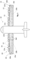
- Fig. 1 shows an aircraft 10 having at least one electrical consumer 12 to be powered by alternating current such as a sinusoidal current and a power electronic system 14 for supplying the electrical consumer 12 with electrical power.
- alternating current such as a sinusoidal current
- power electronic system 14 for supplying the electrical consumer 12 with electrical power.
- the electrical consumer 12 can be of any kind of aircraft component to be powered with AC power such as an electrical actor, a motor pump, or an electric motor M, 16.
- the aircraft 10 has at least one power train 18a-18d equipped with the electrical consumer 12 e.g., the motor 16 and the power electronic system 14.
- the at least one power train 18a-18d is configured as drive of a propulsion system 20 for the aircraft 10.
- each power train 18a-18d has an electrically driven propeller 22a-22d.
- a plurality of propellers 22a-22d is provided on each wing 24a, 24b of the aircraft 10.
- Fig. 2 shows a block diagram of the power electronic system 14 together with the electrical consumer 12 driven thereby.
- the power electronic system 14 is a modular power electronic system with several sub-modules SM1-SM6, shortly referred to as SMx or simply SM.
- Fig. 3 shows a block diagram of the sub-module SM.
- Each sub-module SMx includes an energy storage 26 providing DC power and a preferably bidirectional inverter 28 for converting the DC power into AC power.
- the energy storage 26 is a battery 30 including one or preferably several battery cells 32.
- a capacity 34 is connected in parallel to the energy storage 26.
- the inverter 28 includes several power switching elements 36.
- the inverter 28 is configured as a full-bridge inverter.
- an output filter 38 is provided at the output terminal of the inverter 28.
- AC bus 40 carrying sinusoidal currents only.
- the AC bus 40 further connects the electrical consumer 20 to the power electronic system 14.
- the power electronic system 14 is configured as a multi-phase system wherein each phase u, v, w includes a plurality of sub-modules SMx. In the embodiment shown, each phase u, v, w has the same number of sub-modules SMx each configured as shown in Fig. 3 .
- the sub-modules SMx of each power train 18a-18d are distributed in the corresponding wing 24a, 24b.
- preferred embodiments of the power electronic system 14 are configured as an inverter system 42 composed of multiple submodules SM, SMx, SM1-SM6 that are connected in series. There is provided the same amount of SMs for each phase u, v, w, in a multi-phase power system.
- each SM also has its own energy storage 26 and comes preferably with a small output filter 38, most preferred an LC-filter with PT2 behaviour (see e.g. [1]). Due to that, the complete energy storage system can be divided into x sub systems that are much smaller and more lightweight.
- the output filter 38 is a typical low pass filter (PT1 behaviour). Of course, other filter techniques can also be used.
- the SMs can be distributed more widely as there are only sinusoidal shaped currents flowing between the single SMs and the motor M, 16.
- each submodule SM which allows it to get rid of any kind of DC-breaker. Due to the high current capability of actual batteries 30, the SM-DC-link can be very small and only needs to absorb energy during the commutation phase. Typically, large DC-link capacitors are not needed anymore.
- a power electronic system (14) for providing an aircraft component with electrical power comprising a plurality of sub-modules (SM1-SM6, SM) each including an energy storage (26) and an inverter (28).
- each sub-module has a small output filter (38).
Landscapes
- Engineering & Computer Science (AREA)
- Power Engineering (AREA)
- Inverter Devices (AREA)
Abstract
In order to provide a new inverter architecture with high flexibility regarding the installation flexibility as well as an improved redundancy and fail-safe operation capability, the invention provides a power electronic system (14) for providing an aircraft component with electrical power, the power electronic system (14) comprising a plurality of sub-modules (SM1-SM6, SM) each including an energy storage (26) and an inverter (28). In preferred embodiments, each sub-module also comprises a small output filter (38).
Description
- The invention relates to a power electronic system for providing an aircraft component, especially a drive train, with electrical power. Further, the invention relates to a sub-module for such power electronic system. Still further, the invention relates to a power train for an aircraft and an aircraft equipped with such power electronic system as well as to an operation method therefore.
- For technical background, reference is made to the following literature:
- [1] Wikipedia, PT2-Glied, download from https://de.wikipedia.org/w/index.php?title=PT2-Glied&oldid=229466572 on October 10, 2023.
- State of the art power electronics systems for e.g., drivetrain applications consist of a centralized energy storage system (large battery), combined with at least one inverter.
- An object of the invention is to provide a new inverter architecture with high flexibility regarding the installation flexibility as well as an improved redundancy and fail-safe operation capability.
- For achieving such object, the invention provides a power electronic system according to claim 1. Preferred uses of such power electronic systems and a sub-module therefore are subject matters of the further independent claims.
- Advantageous embodiments are subject-matters of the dependent claims.
- The invention provides according to a first aspect thereof a power electronic system for providing an aircraft component with electrical power, the power electronic system comprising a plurality of sub-modules each including an energy storage and an inverter.
- In some embodiments, the inverter is configured to invert a DC power of the energy storage into AC power for the aircraft component.
- In some embodiments, the power electronic system comprises at least a first and a second sub-module connected in series.
- In some embodiments, the power electronic system is configured as a multi-phase power system wherein each phase comprises a plurality of the sub-modules, especially such that each phase comprises the same number of sub-modules.
- In some embodiments, the energy storage of each sub-module comprises at least one batterie cell or several batterie cells.
- Especially, the inverter of each sub-module is configured to operate bi-directionally.
- In some embodiments, each sub-module comprises a capacitor connected parallel to the energy storage.
- In preferred embodiments, each sub-module comprises an output filter. Preferably, the output filter is provided at the output of the inverter.
- In some embodiments, the output filter is a LC filter with PT2 behaviour. For the definition of PT2 behaviour, see for example the literature [1]. In some embodiments, the output filter is a sine filter. In some embodiments, the output filter is a low pass filter, especially with PT1 behaviour.
- In some embodiments, the sub-modules are connected with a bus for carrying only sinusoidal currents.
- In some embodiments, the power electronic system is configured such that DC power is only transmitted within the sub-modules.
- According to another aspect, the invention provides a sub-module for a power electronic system according to any of the aforementioned embodiments, comprising a DC energy storage and an inverter for inverting DC power of the energy storage to AC power at the output of the sub-module.
- According to another aspect, the invention provides a power train for an aircraft comprising an electrical consumer and a power electronic system according to any of the claims 1 to 9 for supplying the electrical consumer with AC power.
- In some embodiments, the electrical consumer includes an electric motor, especially for a propulsion component of the aircraft.
- According to another aspect, the invention provides an aircraft comprising a power-electronic system according to any of the aforementioned embodiments or a power train according to any of the aforementioned embodiments.
- In some embodiments, the aircraft comprises a propulsion component on or in a wing of the aircraft wherein the propulsion component is driven by the power electronic system wherein the sub-modules thereof are distributed within the wing.
- According to another aspect, the invention provides a method for operating a power electronic system according to any of the aforementioned embodiments, wherein the sub-modules are controlled like a multi-level inverter.
- Preferred embodiments of the invention relate to a battery cell-based inverter for aircraft applications.
- Preferred embodiments of the invention relate to power electronics and optimized inverters.
- State of art multilevel inverters are composed of multiple switching units (submodules (SM)), put in series to overcome the voltage limitations of single semiconductor devices. Additionally, multilevel systems allow for finer gradation of the output voltage, thus drastically reducing interference emissions and the required filtering effort. Standard multilevel systems contain filters at the output of each phase leg to minimize remaining disturbances.
- In some embodiments, a new inverter architecture is provided that benefits from distributed energy storages directly linked to the inverters. In some embodiments, the system is modular and multilevel and comes with the already known benefits like low EMI disturbance and less filter effort. The direct integration of an energy storage system into each single submodule eases scalability, reduces EMI disturbances and allows to build a redundant system without large overhead.
- According to preferred embodiments, no long leads (busbars) are needed anymore due to the direct coupling between inverter and energy storage (battery).
- Additionally, in some embodiments, the DC-link capacitor can be minimized (only commutation energy has to be provided by the capacitor) and therefore weight can be reduced. In some embodiments, the inverters operate bidirectionally so that charging, discharging and balancing of the single batteries is possible.
- Due to the multiple submodules and energy sources, a high amount of reliability and fail safety is achieved. In failure cases of one or even multiple submodules (battery or inverter) the defect submodule can be easily bypassed and the complete system further operated.
- Additionally, in some embodiments, much more flexibility regarding installation is given due to the smaller sub-components that can be placed decentralized.
- For example, talking about a multi propeller aircraft with 2 props in each wing this could mean e.g., each prop has its own power electronics and energy storage system which is distributed across the whole wing.
- To sum up, preferred embodiments of invention offer at least one, several or all of the following benefits:
- Redundancy is provided for
- Battery
- Electronic
- No additional charging infrastructure is necessary
- An enhanced weight distribution is possible (modular system with equal bricks)
- A scalable system is provided (higher voltage and or current ratings with additional SMs)
- no DC-Bus is needed, as result no DC breaker exists/is needed
- a bus connected the system component "carries" only sinusoidal currents this results in low EMI
- the system can be controlled like a multilevel inverter; as result only low voltage semiconductors (high efficiency) are needed, and only a low EMI arises
- Submodules can be placed "independent" of each other and can be distributed across a wide area
- A preferred embodiment of the proposed system (based on e.g. a MMC topology) describes an inverter system based on submodules, which does not have the output filter at the phase output, but instead each individual submodule is equipped with a more efficient, small and lightweight filter.
- Some embodiments of the invention comprise an inverter system composed of multiple submodules (SM) that are connected in series. Preferably, there is the same amount of SMs for each phase in a multi phase power system. In contrast to state of art systems, each SM also has its own energy storage and comes with a small output filter. This could be a typical low pass filter (PT1-behavior) or a sine-filter (LG-filter) with PT2 -behavior which is commonly used in inverter applications. Of course, other filter technologies are also conceivable.
- Due to the integrated filter each connection between the submodules and the connection to the load show a good sine approximation. This leads to drastic reduction of common- and differential -mode disturbances as well as EMI interference.
- Due to the integration of the filter inside each submodule some advantages can be realized:
- Each filter only affects a fraction of the total voltage and can therefore be designed much more efficiently.
- Additionally, the components used can be designed for lower voltages, which typically minimizes the required space.
- By applying sinus filtering to each submodule, the connections between the individual submodules become more sinusoidal, which can significantly reduce interference emissions, especially in modules that are spatially separated (typically in high voltage/high power areas).
- By integrating into each SM, the manufacturing process of the overall inverter can also be optimized, and by using, for example, SMD filter components, space and weight can be saved.
- In general, using smaller components can result in a higher quality factor.
- Embodiments of the invention are explained below referring to the accompanying drawings in which:
- Fig. 1
- is a schematic plan view of an embodiment of an aircraft with an electric drive train and an inverter architecture according to an exemplary embodiment of the invention;
- Fig. 2
- is a block diagram of the drive train with the inverter structure including several sub-modules SMx; and
- Fig. 3
- is a block diagram of one of the sub-modules SMx according to an exemplary embodiment of the invention.
-
Fig. 1 shows anaircraft 10 having at least oneelectrical consumer 12 to be powered by alternating current such as a sinusoidal current and a powerelectronic system 14 for supplying theelectrical consumer 12 with electrical power. - The
electrical consumer 12 can be of any kind of aircraft component to be powered with AC power such as an electrical actor, a motor pump, or an electric motor M, 16. - Especially, the
aircraft 10 has at least onepower train 18a-18d equipped with theelectrical consumer 12 e.g., themotor 16 and the powerelectronic system 14. In the embodiment shown, the at least onepower train 18a-18d is configured as drive of apropulsion system 20 for theaircraft 10. For example, eachpower train 18a-18d has an electrically drivenpropeller 22a-22d. In the embodiment shown, a plurality ofpropellers 22a-22d is provided on eachwing aircraft 10. -
Fig. 2 shows a block diagram of the powerelectronic system 14 together with theelectrical consumer 12 driven thereby. The powerelectronic system 14 is a modular power electronic system with several sub-modules SM1-SM6, shortly referred to as SMx or simply SM. -
Fig. 3 shows a block diagram of the sub-module SM. Each sub-module SMx includes anenergy storage 26 providing DC power and a preferablybidirectional inverter 28 for converting the DC power into AC power. - In some embodiments, the
energy storage 26 is abattery 30 including one or preferablyseveral battery cells 32. Acapacity 34 is connected in parallel to theenergy storage 26. - The
inverter 28 includes severalpower switching elements 36. For example, theinverter 28 is configured as a full-bridge inverter. In some embodiments, an output filter 38 is provided at the output terminal of theinverter 28. - Referring to
Fig. 2 , several sub-modules SMx are connected in series by anAC bus 40 carrying sinusoidal currents only. TheAC bus 40 further connects theelectrical consumer 20 to the powerelectronic system 14. - In some embodiments, the power
electronic system 14 is configured as a multi-phase system wherein each phase u, v, w includes a plurality of sub-modules SMx. In the embodiment shown, each phase u, v, w has the same number of sub-modules SMx each configured as shown inFig. 3 . - Referring again to
Fig. 1 , the sub-modules SMx of eachpower train 18a-18d are distributed in thecorresponding wing - Referring again to
Figs. 2 and 3 , preferred embodiments of the powerelectronic system 14 are configured as an inverter system 42 composed of multiple submodules SM, SMx, SM1-SM6 that are connected in series. There is provided the same amount of SMs for each phase u, v, w, in a multi-phase power system. In contrast to state-of-the-art systems, each SM also has itsown energy storage 26 and comes preferably with a small output filter 38, most preferred an LC-filter with PT2 behaviour (see e.g. [1]). Due to that, the complete energy storage system can be divided into x sub systems that are much smaller and more lightweight. In other embodiments, the output filter 38 is a typical low pass filter (PT1 behaviour). Of course, other filter techniques can also be used. - Additionally, the SMs can be distributed more widely as there are only sinusoidal shaped currents flowing between the single SMs and the motor M, 16.
- The DC-part only exists inside each submodule SM which allows it to get rid of any kind of DC-breaker. Due to the high current capability of
actual batteries 30, the SM-DC-link can be very small and only needs to absorb energy during the commutation phase. Typically, large DC-link capacitors are not needed anymore. - In order to provide a new inverter architecture with high flexibility regarding the installation flexibility as well as an improved redundancy and fail-safe operation capability, a power electronic system (14) for providing an aircraft component with electrical power has been described, the power electronic system (14) comprising a plurality of sub-modules (SM1-SM6, SM) each including an energy storage (26) and an inverter (28). Preferably, each sub-module has a small output filter (38).
-
- 10
- aircraft
- 12
- electrical consumer
- 14
- power electronic system
- 16, M
- motor
- 18a-18d
- power train
- 20
- propulsion system
- 22a-22d
- propeller
- 24a, 24b
- wing
- 26
- energy storage
- 28
- inverter
- 30
- battery
- 32
- battery cell
- 34
- capacitor
- 36
- power switching element
- 38
- output filter
- 40
- AC bus
- 42
- inverter system
- u, v, w
- phase
Claims (15)
- Power electronic system (14) for providing an aircraft component with electrical power, the power electronic system (14) comprising a plurality of sub-modules (SM1-SM6, SM) each including an energy storage (26) and an inverter (28).
- Power electronic system (14) according to claim 1, wherein each sub-module (SM1-SM6, SM) comprises an output filter (38), preferably at the output of the inverter (28).
- Power electronic system (14) according to claim 2, wherein the output filter (38) is3.1 a low pass filter or3.2 a filter, especially low pass filter, with PT1 behaviour or3.3 a sine-filter or3.4 a LC filter with PT2 behaviour.
- Power electronic system (14) according to any of the preceding claims, wherein the inverter (28) is configured to invert a DC power of the energy storage (26) into AC power for the aircraft component.
- Power electronic system (14) according to any of the preceding claims, comprising at least a first and a second sub-module (SM1, SM2) connected in series.
- Power electronic system (14) according to any of the preceding claims, configured as a multi-phase power system wherein each phase (u, v, w) comprises a plurality of the sub-modules (SM1-SM6, SM), especially such that each phase (u, v, w) comprises the same number of sub-modules (SM1-SM6, SM).
- Power electronic system (14) according to any of the preceding claims wherein7.1 the energy storage (26) of each sub-module (SM1-SM6, SM) comprises at least one or several batterie cells (32) and/or7.2 the inverter (28) of each sub-module is configured to operate bi-directionally and/or7.3 wherein each sub-module (SM1-SM6, SM) comprises a capacitor (34) connected in a DC link parallel to the energy storage (26).
- Power electronic system (14) according to any of the preceding claims wherein the sub-modules (SM1-SM6, SM) are connected with a bus (40) for carrying only sinusoidal currents.
- Power electronic system (14) according to any of the preceding claims configured such that DC power is only transmitted within the sub-modules (SM1-SM6, SM).
- Sub-module (SM1-SM6, SM) for a power electronic system (14) according to any of the preceding claims, comprising a DC energy storage (26) and an inverter (28) for inverting DC power of the energy storage (26) to AC power at the output of the sub-module (SM1-SM6, SM), and optionally an output filter (38).
- Power train (18a-18d) for an aircraft (10) comprising an electrical consumer (12) and a power electronic system (14) according to any of the claims 1 to 9 for supplying the electrical consumer with AC power.
- Power train (18a-18d) according to claim 11, wherein the electrical consumer (12) includes an electric motor (M, 16), especially for a propulsion component (22a-22d) of the aircraft (10).
- Aircraft (10) comprising a power-electronic system (14) according to any of the claims 1 to 9 or a power train (18a-18d) according to any of the claims 11 or 12.
- Aircraft (10) according to claim 13, comprising a propulsion component (22a-22d) on or in a wing (24a, 24b) of the aircraft (10) wherein the propulsion component (22a-22d) is driven by the power electronic system (18a-18d) and wherein the sub-modules (SM1-SM6, SM) thereof are distributed within the wing (24a, 24b).
- Method for operating a power electronic system (14) according to any of the claims 1 to 9, wherein the sub-modules (SM1-SM6, SM) are controlled like a multi-level inverter.
Priority Applications (1)
| Application Number | Priority Date | Filing Date | Title |
|---|---|---|---|
| CN202511477588.4A CN122001037A (en) | 2023-11-10 | 2025-10-16 | Modular power electronics system for an aircraft comprising several inverter sub-modules with energy storage means |
Applications Claiming Priority (1)
| Application Number | Priority Date | Filing Date | Title |
|---|---|---|---|
| EP23209114.0A EP4554040A1 (en) | 2023-11-10 | 2023-11-10 | Modular power electronic system for an aircraft including several inverter sub-modules with energy storage |
Publications (1)
| Publication Number | Publication Date |
|---|---|
| EP4554042A1 true EP4554042A1 (en) | 2025-05-14 |
Family
ID=88779508
Family Applications (2)
| Application Number | Title | Priority Date | Filing Date |
|---|---|---|---|
| EP23209114.0A Withdrawn EP4554040A1 (en) | 2023-11-10 | 2023-11-10 | Modular power electronic system for an aircraft including several inverter sub-modules with energy storage |
| EP24211778.6A Pending EP4554042A1 (en) | 2023-11-10 | 2024-11-08 | Modular power electronic system for an aircraft including several inverter sub-modules with energy storage |
Family Applications Before (1)
| Application Number | Title | Priority Date | Filing Date |
|---|---|---|---|
| EP23209114.0A Withdrawn EP4554040A1 (en) | 2023-11-10 | 2023-11-10 | Modular power electronic system for an aircraft including several inverter sub-modules with energy storage |
Country Status (2)
| Country | Link |
|---|---|
| EP (2) | EP4554040A1 (en) |
| CN (1) | CN122001037A (en) |
Citations (3)
| Publication number | Priority date | Publication date | Assignee | Title |
|---|---|---|---|---|
| EP3213952A1 (en) * | 2016-03-02 | 2017-09-06 | Airbus Defence and Space GmbH | Electric drive system for an aircraft and method of operating same |
| US20210044216A1 (en) * | 2018-01-25 | 2021-02-11 | Auckland Uniservices Limited | A multi-level modular converter |
| US20230018916A1 (en) * | 2021-07-16 | 2023-01-19 | Rolls-Royce Plc | Rectifier |
-
2023
- 2023-11-10 EP EP23209114.0A patent/EP4554040A1/en not_active Withdrawn
-
2024
- 2024-11-08 EP EP24211778.6A patent/EP4554042A1/en active Pending
-
2025
- 2025-10-16 CN CN202511477588.4A patent/CN122001037A/en active Pending
Patent Citations (3)
| Publication number | Priority date | Publication date | Assignee | Title |
|---|---|---|---|---|
| EP3213952A1 (en) * | 2016-03-02 | 2017-09-06 | Airbus Defence and Space GmbH | Electric drive system for an aircraft and method of operating same |
| US20210044216A1 (en) * | 2018-01-25 | 2021-02-11 | Auckland Uniservices Limited | A multi-level modular converter |
| US20230018916A1 (en) * | 2021-07-16 | 2023-01-19 | Rolls-Royce Plc | Rectifier |
Non-Patent Citations (2)
| Title |
|---|
| KRASTEV IVAN ET AL: "Boost Multilevel Cascade Inverter for Hydrogen Fuel Cell Light Railway Vehicles", IEEE TRANSACTIONS ON INDUSTRIAL ELECTRONICS, IEEE SERVICE CENTER, PISCATAWAY, NJ, USA, vol. 69, no. 8, 25 August 2021 (2021-08-25), pages 7837 - 7847, XP011901989, ISSN: 0278-0046, [retrieved on 20220303], DOI: 10.1109/TIE.2021.3105992 * |
| XU LUONA ET AL: "A Review of DC Shipboard Microgrids-Part I: Power Architectures, Energy Storage, and Power Converters", IEEE TRANSACTIONS ON POWER ELECTRONICS, INSTITUTE OF ELECTRICAL AND ELECTRONICS ENGINEERS, USA, vol. 37, no. 5, 16 November 2021 (2021-11-16), pages 5155 - 5172, XP011898497, ISSN: 0885-8993, [retrieved on 20220119], DOI: 10.1109/TPEL.2021.3128417 * |
Also Published As
| Publication number | Publication date |
|---|---|
| EP4554040A1 (en) | 2025-05-14 |
| CN122001037A (en) | 2026-05-08 |
Similar Documents
| Publication | Publication Date | Title |
|---|---|---|
| US9899948B2 (en) | Electric drive system | |
| US11799392B2 (en) | Low-volt decoupling from a modular energy store converter system | |
| RU2565586C2 (en) | Layout of power supply unit using modular electronic modules | |
| DK2241001T3 (en) | Inverter | |
| US10560019B2 (en) | Bipolar high-voltage network and method for operating a bipolar high-voltage network | |
| Kuder et al. | Battery modular multilevel management (bm3) converter applied at battery cell level for electric vehicles and energy storages | |
| Aishwarya et al. | Review of reduced‐switch multilevel inverters for electric vehicle applications | |
| US9293946B2 (en) | Systems and methods for uninterruptible power supplies with bidirectional power converters | |
| US8879292B2 (en) | Multipoint converters with brake chopper | |
| US20120112545A1 (en) | M2LC System Coupled to a Rectifier System | |
| JP7286887B2 (en) | SST system with multiple LVDC outputs | |
| US11888398B2 (en) | Self reconfigurable, adaptable power electronics building block (A-PEBB) | |
| WO2014026840A2 (en) | Electrical power distribution system for data centers | |
| US11056967B2 (en) | Electrical supply system for an aircraft with a legacy AC network and a bipolar DC network | |
| CN105322607B (en) | For providing voltage, there is the series connection device and drive arrangement of group current transformer | |
| EP3048689B1 (en) | Direct current power system | |
| US20220302843A1 (en) | Auxiliary voltage supply for power converter and use thereof in vehicles | |
| EP4554040A1 (en) | Modular power electronic system for an aircraft including several inverter sub-modules with energy storage | |
| US12283897B2 (en) | Modular multi-level converter | |
| WO2024167492A1 (en) | Cell bypass for variable frequency drives | |
| US11916493B2 (en) | Power converter | |
| US20250257714A1 (en) | Supplying power to auxiliary wind turbine equipment | |
| EP3820040A1 (en) | Multiphase current-fed modular multilevel converter |
Legal Events
| Date | Code | Title | Description |
|---|---|---|---|
| PUAI | Public reference made under article 153(3) epc to a published international application that has entered the european phase |
Free format text: ORIGINAL CODE: 0009012 |
|
| STAA | Information on the status of an ep patent application or granted ep patent |
Free format text: STATUS: THE APPLICATION HAS BEEN PUBLISHED |
|
| AK | Designated contracting states |
Kind code of ref document: A1 Designated state(s): AL AT BE BG CH CY CZ DE DK EE ES FI FR GB GR HR HU IE IS IT LI LT LU LV MC ME MK MT NL NO PL PT RO RS SE SI SK SM TR |
|
| STAA | Information on the status of an ep patent application or granted ep patent |
Free format text: STATUS: REQUEST FOR EXAMINATION WAS MADE |
|
| 17P | Request for examination filed |
Effective date: 20251111 |