EP4554008A1 - An electrical connector - Google Patents
An electrical connector Download PDFInfo
- Publication number
- EP4554008A1 EP4554008A1 EP23208657.9A EP23208657A EP4554008A1 EP 4554008 A1 EP4554008 A1 EP 4554008A1 EP 23208657 A EP23208657 A EP 23208657A EP 4554008 A1 EP4554008 A1 EP 4554008A1
- Authority
- EP
- European Patent Office
- Prior art keywords
- electrical
- electrical contact
- housing
- electrical connector
- contact
- Prior art date
- Legal status (The legal status is an assumption and is not a legal conclusion. Google has not performed a legal analysis and makes no representation as to the accuracy of the status listed.)
- Pending
Links
Images

Classifications
-
- H—ELECTRICITY
- H01—ELECTRIC ELEMENTS
- H01R—ELECTRICALLY-CONDUCTIVE CONNECTIONS; STRUCTURAL ASSOCIATIONS OF A PLURALITY OF MUTUALLY-INSULATED ELECTRICAL CONNECTING ELEMENTS; COUPLING DEVICES; CURRENT COLLECTORS
- H01R9/00—Structural associations of a plurality of mutually-insulated electrical connecting elements, e.g. terminal strips or terminal blocks; Terminals or binding posts mounted upon a base or in a case; Bases therefor
- H01R9/03—Connectors arranged to contact a plurality of the conductors of a multiconductor cable, e.g. tapping connections
- H01R9/05—Connectors arranged to contact a plurality of the conductors of a multiconductor cable, e.g. tapping connections for coaxial cables
- H01R9/0512—Connections to an additional grounding conductor
-
- H—ELECTRICITY
- H01—ELECTRIC ELEMENTS
- H01R—ELECTRICALLY-CONDUCTIVE CONNECTIONS; STRUCTURAL ASSOCIATIONS OF A PLURALITY OF MUTUALLY-INSULATED ELECTRICAL CONNECTING ELEMENTS; COUPLING DEVICES; CURRENT COLLECTORS
- H01R11/00—Individual connecting elements providing two or more spaced connecting locations for conductive members which are, or may be, thereby interconnected, e.g. end pieces for wires or cables supported by the wire or cable and having means for facilitating electrical connection to some other wire, terminal, or conductive member, blocks of binding posts
- H01R11/01—Individual connecting elements providing two or more spaced connecting locations for conductive members which are, or may be, thereby interconnected, e.g. end pieces for wires or cables supported by the wire or cable and having means for facilitating electrical connection to some other wire, terminal, or conductive member, blocks of binding posts characterised by the form or arrangement of the conductive interconnection between the connecting locations
-
- H—ELECTRICITY
- H01—ELECTRIC ELEMENTS
- H01R—ELECTRICALLY-CONDUCTIVE CONNECTIONS; STRUCTURAL ASSOCIATIONS OF A PLURALITY OF MUTUALLY-INSULATED ELECTRICAL CONNECTING ELEMENTS; COUPLING DEVICES; CURRENT COLLECTORS
- H01R13/00—Details of coupling devices of the kinds covered by groups H01R12/70 or H01R24/00 - H01R33/00
- H01R13/46—Bases; Cases
- H01R13/502—Bases; Cases composed of different pieces
-
- H—ELECTRICITY
- H01—ELECTRIC ELEMENTS
- H01R—ELECTRICALLY-CONDUCTIVE CONNECTIONS; STRUCTURAL ASSOCIATIONS OF A PLURALITY OF MUTUALLY-INSULATED ELECTRICAL CONNECTING ELEMENTS; COUPLING DEVICES; CURRENT COLLECTORS
- H01R13/00—Details of coupling devices of the kinds covered by groups H01R12/70 or H01R24/00 - H01R33/00
- H01R13/648—Protective earth or shield arrangements on coupling devices, e.g. anti-static shielding
- H01R13/658—High frequency shielding arrangements, e.g. against EMI [Electro-Magnetic Interference] or EMP [Electro-Magnetic Pulse]
- H01R13/6581—Shield structure
-
- H—ELECTRICITY
- H01—ELECTRIC ELEMENTS
- H01R—ELECTRICALLY-CONDUCTIVE CONNECTIONS; STRUCTURAL ASSOCIATIONS OF A PLURALITY OF MUTUALLY-INSULATED ELECTRICAL CONNECTING ELEMENTS; COUPLING DEVICES; CURRENT COLLECTORS
- H01R24/00—Two-part coupling devices, or either of their cooperating parts, characterised by their overall structure
- H01R24/38—Two-part coupling devices, or either of their cooperating parts, characterised by their overall structure having concentrically or coaxially arranged contacts
-
- H—ELECTRICITY
- H01—ELECTRIC ELEMENTS
- H01R—ELECTRICALLY-CONDUCTIVE CONNECTIONS; STRUCTURAL ASSOCIATIONS OF A PLURALITY OF MUTUALLY-INSULATED ELECTRICAL CONNECTING ELEMENTS; COUPLING DEVICES; CURRENT COLLECTORS
- H01R4/00—Electrically-conductive connections between two or more conductive members in direct contact, i.e. touching one another; Means for effecting or maintaining such contact; Electrically-conductive connections having two or more spaced connecting locations for conductors and using contact members penetrating insulation
- H01R4/28—Clamped connections, spring connections
- H01R4/30—Clamped connections, spring connections utilising a screw or nut clamping member
- H01R4/34—Conductive members located under head of screw
-
- H—ELECTRICITY
- H02—GENERATION; CONVERSION OR DISTRIBUTION OF ELECTRIC POWER
- H02G—INSTALLATION OF ELECTRIC CABLES OR LINES, OR OF COMBINED OPTICAL AND ELECTRIC CABLES OR LINES
- H02G15/00—Cable fittings
- H02G15/013—Sealing means for cable inlets
-
- H—ELECTRICITY
- H02—GENERATION; CONVERSION OR DISTRIBUTION OF ELECTRIC POWER
- H02G—INSTALLATION OF ELECTRIC CABLES OR LINES, OR OF COMBINED OPTICAL AND ELECTRIC CABLES OR LINES
- H02G15/00—Cable fittings
- H02G15/02—Cable terminations
- H02G15/04—Cable-end sealings
-
- B—PERFORMING OPERATIONS; TRANSPORTING
- B64—AIRCRAFT; AVIATION; COSMONAUTICS
- B64D—EQUIPMENT FOR FITTING IN OR TO AIRCRAFT; FLIGHT SUITS; PARACHUTES; ARRANGEMENT OR MOUNTING OF POWER PLANTS OR PROPULSION TRANSMISSIONS IN AIRCRAFT
- B64D11/00—Passenger or crew accommodation; Flight-deck installations not otherwise provided for
- B64D11/06—Arrangements of seats, or adaptations or details specially adapted for aircraft seats
- B64D11/0624—Arrangements of electrical connectors, e.g. for earphone, internet or electric supply
-
- B—PERFORMING OPERATIONS; TRANSPORTING
- B64—AIRCRAFT; AVIATION; COSMONAUTICS
- B64D—EQUIPMENT FOR FITTING IN OR TO AIRCRAFT; FLIGHT SUITS; PARACHUTES; ARRANGEMENT OR MOUNTING OF POWER PLANTS OR PROPULSION TRANSMISSIONS IN AIRCRAFT
- B64D2221/00—Electric power distribution systems onboard aircraft
-
- H—ELECTRICITY
- H01—ELECTRIC ELEMENTS
- H01R—ELECTRICALLY-CONDUCTIVE CONNECTIONS; STRUCTURAL ASSOCIATIONS OF A PLURALITY OF MUTUALLY-INSULATED ELECTRICAL CONNECTING ELEMENTS; COUPLING DEVICES; CURRENT COLLECTORS
- H01R11/00—Individual connecting elements providing two or more spaced connecting locations for conductive members which are, or may be, thereby interconnected, e.g. end pieces for wires or cables supported by the wire or cable and having means for facilitating electrical connection to some other wire, terminal, or conductive member, blocks of binding posts
- H01R11/03—Individual connecting elements providing two or more spaced connecting locations for conductive members which are, or may be, thereby interconnected, e.g. end pieces for wires or cables supported by the wire or cable and having means for facilitating electrical connection to some other wire, terminal, or conductive member, blocks of binding posts characterised by the relationship between the connecting locations
- H01R11/05—Individual connecting elements providing two or more spaced connecting locations for conductive members which are, or may be, thereby interconnected, e.g. end pieces for wires or cables supported by the wire or cable and having means for facilitating electrical connection to some other wire, terminal, or conductive member, blocks of binding posts characterised by the relationship between the connecting locations the connecting locations having different types of direct connections
-
- H—ELECTRICITY
- H01—ELECTRIC ELEMENTS
- H01R—ELECTRICALLY-CONDUCTIVE CONNECTIONS; STRUCTURAL ASSOCIATIONS OF A PLURALITY OF MUTUALLY-INSULATED ELECTRICAL CONNECTING ELEMENTS; COUPLING DEVICES; CURRENT COLLECTORS
- H01R13/00—Details of coupling devices of the kinds covered by groups H01R12/70 or H01R24/00 - H01R33/00
- H01R13/46—Bases; Cases
- H01R13/533—Bases, cases made for use in extreme conditions, e.g. high temperature, radiation, vibration, corrosive environment, pressure
-
- H—ELECTRICITY
- H01—ELECTRIC ELEMENTS
- H01R—ELECTRICALLY-CONDUCTIVE CONNECTIONS; STRUCTURAL ASSOCIATIONS OF A PLURALITY OF MUTUALLY-INSULATED ELECTRICAL CONNECTING ELEMENTS; COUPLING DEVICES; CURRENT COLLECTORS
- H01R13/00—Details of coupling devices of the kinds covered by groups H01R12/70 or H01R24/00 - H01R33/00
- H01R13/62—Means for facilitating engagement or disengagement of coupling parts or for holding them in engagement
- H01R13/622—Screw-ring or screw-casing
-
- H—ELECTRICITY
- H01—ELECTRIC ELEMENTS
- H01R—ELECTRICALLY-CONDUCTIVE CONNECTIONS; STRUCTURAL ASSOCIATIONS OF A PLURALITY OF MUTUALLY-INSULATED ELECTRICAL CONNECTING ELEMENTS; COUPLING DEVICES; CURRENT COLLECTORS
- H01R13/00—Details of coupling devices of the kinds covered by groups H01R12/70 or H01R24/00 - H01R33/00
- H01R13/648—Protective earth or shield arrangements on coupling devices, e.g. anti-static shielding
- H01R13/658—High frequency shielding arrangements, e.g. against EMI [Electro-Magnetic Interference] or EMP [Electro-Magnetic Pulse]
- H01R13/6591—Specific features or arrangements of connection of shield to conductive members
- H01R13/6592—Specific features or arrangements of connection of shield to conductive members the conductive member being a shielded cable
-
- H—ELECTRICITY
- H01—ELECTRIC ELEMENTS
- H01R—ELECTRICALLY-CONDUCTIVE CONNECTIONS; STRUCTURAL ASSOCIATIONS OF A PLURALITY OF MUTUALLY-INSULATED ELECTRICAL CONNECTING ELEMENTS; COUPLING DEVICES; CURRENT COLLECTORS
- H01R2201/00—Connectors or connections adapted for particular applications
- H01R2201/26—Connectors or connections adapted for particular applications for vehicles
-
- H—ELECTRICITY
- H01—ELECTRIC ELEMENTS
- H01R—ELECTRICALLY-CONDUCTIVE CONNECTIONS; STRUCTURAL ASSOCIATIONS OF A PLURALITY OF MUTUALLY-INSULATED ELECTRICAL CONNECTING ELEMENTS; COUPLING DEVICES; CURRENT COLLECTORS
- H01R4/00—Electrically-conductive connections between two or more conductive members in direct contact, i.e. touching one another; Means for effecting or maintaining such contact; Electrically-conductive connections having two or more spaced connecting locations for conductors and using contact members penetrating insulation
- H01R4/28—Clamped connections, spring connections
- H01R4/30—Clamped connections, spring connections utilising a screw or nut clamping member
- H01R4/302—Clamped connections, spring connections utilising a screw or nut clamping member having means for preventing loosening of screw or nut, e.g. vibration-proof connection
-
- H—ELECTRICITY
- H01—ELECTRIC ELEMENTS
- H01R—ELECTRICALLY-CONDUCTIVE CONNECTIONS; STRUCTURAL ASSOCIATIONS OF A PLURALITY OF MUTUALLY-INSULATED ELECTRICAL CONNECTING ELEMENTS; COUPLING DEVICES; CURRENT COLLECTORS
- H01R4/00—Electrically-conductive connections between two or more conductive members in direct contact, i.e. touching one another; Means for effecting or maintaining such contact; Electrically-conductive connections having two or more spaced connecting locations for conductors and using contact members penetrating insulation
- H01R4/70—Insulation of connections
- H01R4/72—Insulation of connections using a heat shrinking insulating sleeve
-
- H—ELECTRICITY
- H01—ELECTRIC ELEMENTS
- H01R—ELECTRICALLY-CONDUCTIVE CONNECTIONS; STRUCTURAL ASSOCIATIONS OF A PLURALITY OF MUTUALLY-INSULATED ELECTRICAL CONNECTING ELEMENTS; COUPLING DEVICES; CURRENT COLLECTORS
- H01R9/00—Structural associations of a plurality of mutually-insulated electrical connecting elements, e.g. terminal strips or terminal blocks; Terminals or binding posts mounted upon a base or in a case; Bases therefor
- H01R9/03—Connectors arranged to contact a plurality of the conductors of a multiconductor cable, e.g. tapping connections
- H01R9/05—Connectors arranged to contact a plurality of the conductors of a multiconductor cable, e.g. tapping connections for coaxial cables
- H01R9/0524—Connection to outer conductor by action of a clamping member, e.g. screw fastening means
Definitions
- This disclosure relates to an electrical connector for an aircraft power system, a kit of parts for an electrical connector, an aircraft and an electrical terminal.
- an electrical connector for an aircraft power system comprising: a first electrical contact; a second electrical contact; a housing; and a fixing element, the fixing element extending through the first electrical contact and the second electrical contact to connect the first electrical contact to the second electrical contact, wherein the housing surrounds the first electrical contact and the second electrical contact, the housing comprising electrical insulation to electrically insulate the first and second electrical contacts from an exterior of the housing.
- This configuration helps to ensure the first electrical contact and second electrical contact remain connected during use of the electrical connector, despite the extreme conditions experienced during flight.
- the configuration also allows the electrical connector to be operable with high voltages whilst remaining more lightweight and compact than the alternatives needed for said high voltages.
- the second electrical contact may be configured to receive an electrical wire, such that the first electrical contact and the electrical wire are electrically connected when the electrical wire is inserted into the second electrical contact.
- the second electrical contact may comprise a cavity, the first electrical contact disposed in the cavity to connect the first electrical contact to the second electrical contact.
- the first electrical contact may be coated in a powder insulation layer.
- the fixing element may be a screw.
- Two or more fixing elements may extend through the first electrical contact and second electrical contact.
- the electrical connector may further comprise a thread locking component, the thread locking component configured to prevent rotation of the fixing element.
- This provides a secondary locking mechanism to reduce the risk of the fixing elements separating from the electrical contacts whilst the electrical connector is in use.
- the electrical insulation may comprise an insulative layer of the housing.
- the insulative layer may comprise a ceramic material.
- the electrical connector may further comprise a shielding component, the shielding component configured to shield the electrical connector from an exterior of the shielding component.
- the shielding component may comprise a cable shield, the cable shield surrounding the electrical wire.
- the cable shield may be a conducting braid.
- the shielding component may further comprise a shielding layer, the shielding layer forming part of the housing such that the housing provides shielding.
- the shielding layer may be formed of aluminium.
- a portion of the shielding layer may be exposed to electrically contact the cable shield to the shielding layer.
- the electrical connector may further comprise a clamp band, the clamp band configured to hold the cable shield against a surface of the housing.
- the electrical connector may further comprise a heatshrink layer, the heatshrink layer surrounding the housing and shielding component.
- the housing may comprise a cover and an opening, the opening configured to permit access to the fixing element, the cover configured to close the opening.
- the cover may be a bung.
- the bung may comprise a conducting filling and insulative body.
- the conductive filling may form part of the shielding layer, and the insulative body may form part of the electrical insulation.
- the conductive filling may be formed of aluminium and the insulative body may be formed of silicon.
- a kit of parts for an electrical connector according to the first aspect.
- an aircraft comprising an aircraft power system, the aircraft power system comprising an electrical connector according to the first aspect.
- an electrical terminal for an aircraft comprising: a first electrical contact; a housing; and a fixing element, wherein the fixing element is insertable into the first electrical contact to connect the first electrical contact to a second electrical contact, wherein the housing surrounds the first electrical contact and the second electrical contact when the first electrical contact and second electrical contact are connected to each other, the housing comprising electrical insulation to electrically insulate the first and second electrical contacts from an exterior of the housing.
- the electrical connector 100 comprises a first electrical contact 102, a second electrical contact 104, a housing 105, a first fixing element 106a and a second fixing element 106b.
- the first electrical contact 102 is formed of a flat pin, wherein a surface of the flat pin comprises primary cut outs, the primary cut outs configured to receive the fixing elements 106.
- the first electrical contact 102 may be coated in a powder insulation layer, wherein the powder insulation layer comprises intervals, the intervals configured to allow the first electrical contact 102 to form electrical connections with the fixing elements 106a 106b and/or the second electrical contact 104 (e.g. with the intervals being portions where the powder insulation does not entirely cover the first electrical contact 102 such that an internal conductive portion of the first electrical contact 102 is exposed).
- the second electrical contact 104 is formed of a ring terminal, wherein the ring terminal comprises secondary cut outs, the secondary cut outs configured to receive the fixing elements 106.
- the second electrical contact 104 comprises a cavity 112, wherein the cavity 112 is configured to receive the first electrical contact 102.
- the first electrical contact 102 is disposed in the cavity 112 to connect the first electrical contact 102 to the second electrical contact 104. This means a plurality of surfaces of the first electrical contact 102 may be in direct contact with the second electrical component 104 when the first electrical contact 102 and second electrical contact 104 are connected.
- the cavity 112 is formed between two protruding portions, the second electrical contact 104 comprising the protruding portions.
- the protruding portions extend outwards from a centre of the ring terminal.
- the protruding portions extend in parallel to each other.
- the secondary cut outs are positioned on the protruding portions such that the fixing elements 106a 106b pass through both protruding portions when inserted.
- the first electrical contact 102 can be inserted in between the two protruding portions, such that the fixing elements 106a 106b pass through both protruding portions and the first electrical contact 102 when the fixing elements 106a 106b are inserted into the electrical connector 100.
- the first fixing element 106a and second fixing element 106b extend through the first electrical contact 102 and the second electrical contact 104 to connect the first electrical contact 102 and the second electrical contact 104. When the first electrical contact 102 and second electrical contact 104 are connected, they are electrically coupled.
- the fixing elements 106a 106b are screws.
- the electrical connector 100 further comprises a thread locking component 122, wherein the thread locking component 122 is configured to prevent rotation of the fixing elements 106a 106b.
- the thread locking components 122 are positioned on the second electrical contact 104, such that the first fixing element 106a and second fixing element 106b are fixed to the second electrical contact 104.
- the thread locking component 122 may be an adhesive, such as a methacrylate-based fluid.
- the second electrical contact 104 is configured to receive an electrical wire 110, such that the first electrical contact 102 and the electrical wire 110 are electrically connected when the electrical wire 110 is inserted into the second electrical contact 104.
- crimping may be used to fix the electrical wire 110 to the second electrical contact 104.
- the process of crimping comprises compressing a receiving portion of the second electrical contact 104, wherein the receiving portion contains the electrical wire 110, such that an inner surface of the second electrical contact 104 presses against the electrical wire 110.
- the electrical wire 110 therefore becomes electrically coupled with the second electrical connector 104 and the electrical wire 110 is held in place by the inner surface of the second electrical contact 104.
- the housing 105 surrounds the first electrical contact 102 and second electrical contact 104.
- the housing 105 comprises electrical insulation 107 to electrically insulate the first electrical contact 102 and second electrical contact 104 from an exterior of the housing 105.
- the electrical insulation 107 comprises an insulative layer 108 of the housing 105.
- the insulative layer 108 comprises a ceramic material.
- the housing 105 further comprises a cover 116 and an opening, wherein the opening is configured to permit access to the fixing elements 106.
- the cover 116 is configured to close the opening. This means the fixing elements 106a 106b can be inserted or removed from the electrical contacts 102 104 if the cover 116 is removed, for example if maintenance is required.
- the electrical connector 100 further comprises a shielding component 113.
- the shielding component 113 is configured to shield the electrical connector 100 from an exterior of the shielding component 113. This is achieved as the shielding component 113 is formed of electrically conductive materials connected to an electrical earthing point, therefore producing a conducting grounded shell around elements in an interior of the shielding component 113.
- the shielding component 113 therefore prevents electromagnetic fields originating from the interior of the shielding component 113 reaching the exterior of the shielding component 113.
- the shielding component 113 therefore also prevents electromagnetic signals from the exterior of the shielding component 113 from reaching the interior of the shielding component 113.
- the shielding component 113 comprises a cable shield 114, the cable shield 114 surrounding the electrical wire 110.
- the cable shield 114 comprises a conductive braid, wherein the conductive braid is wrapped around a surface of the electrical wire. The conductive braid runs along a length of the electrical wire 110 to reach an earthing point.
- the shielding component 113 further comprises a shielding layer 115, wherein the shielding layer 115 forms part of the housing 105, such that the housing 105 provides shielding.
- the shielding layer 115 is attached to the insulative layer 108, such that it surrounds a portion of the electrical connector 100.
- the insulative layer 108 may be formed on a surface of the shielding layer 115.
- the shielding layer 115 may provide structure to housing 105.
- the shielding layer may provide structure to the insulative layer 108. A portion of the shielding layer 115 is exposed to electrically contact the cable shield 114. This permits electrical connection between the shielding layer 115 and the cable shield 114.
- the shielding layer 115 is formed of a layer of aluminium, wherein the layer of aluminium is positioned on an inner surface of the insulative layer 108.
- the cover 116 is a bung 116.
- the bung 116 comprises a conductive filling and an insulative body.
- the bung 116 is positioned such that the conductive filling forms part of the shielding component 113, as the conductive filling is in electrical contact with the shielding layer 115.
- the conductive filling may be formed of aluminium.
- the insulative body forms parts of the electrical insulation 107.
- the insulative body may be formed of silicon.
- the electrical connector 100 further comprises a clamp band 120.
- the clamp band 120 may be formed of a ring-shaped body, wherein the ring-shaped body surrounds a portion of the housing 105.
- the clamp band 120 is configured to hold the cable shield 114 against a surface of the housing 105. More specifically, the clamp band 120 is configured to hold the cable shield 114 against the exposed portion of the shielding layer 115 to ensure the cable shield 114 and shielding layer 115 remain in electrical contact.
- the electrical connector 100 further comprises a heatshrink layer 118.
- the heatshrink layer 118 surrounds the housing 105 and shielding component 113, such that the heatshrink layer 118 forms an outer surface of a portion of the electrical connector 100.
- the heatshrink layer 118 comprises a heatshrink material, wherein the heatshrink material is configured to tighten when heat is applied.
- the heatshrink layer 118 therefore presses inward against the housing 105 and shielding component 113 when heated during the installation of the heatshrink layer 118 onto the electrical connector 100. This holds in place components of the electrical connector 100 which are positioned in an interior of the heatshrink layer 118, whilst also providing an additional barrier from an exterior environment of the heatshrink layer 118.
- the heatshrink layer 118 may have an adhesive backing, such that the heatshrink layer 118 can be fixed to the other components of the electrical connector 100.
- the anchor point 202 may also be attached to the housing 105.
- the housing 105 is first placed over the first electrical contact 102.
- the electrical wire 110 is inserted into the second electrical contact 104 and crimped, such that the second electrical contact 104 and the electrical wire 110 are connected.
- the first electrical connector 102 is then inserted into the cavity 112 of the second electrical connector 104, before the fixing elements 106a 106b are inserted through the first electrical contact 102 and second electrical contact 104.
- the fixing elements 106a 106b are inserted via the opening in the housing 105. This means the first electrical contact 102, the second electrical contact 104 and the electrical wire 110 are all electrically coupled.
- the cover 116 is then inserted into the opening of the housing 105.
- the cable shield 114 is wrapped around the electrical wire 110, before the clamp band 120 is used to clamp the cable shield 114 to the exposed portion of the shielding layer 115.
- the heatshrink layer 118 is then slid over the other components of the electrical connector 100 before being heated, such that the heatshrink layer 118 tightens and holds the components of the electrical connector 100 in place.
- the electrical connector 100 is configured to transfer power to/from the terminal box 204 from/to an electrical device, wherein the electrical device is electrically connected to the electrical wire 110.
- the electrical insulation 107 electrically insulates the electrical connector 100.
- the shielding component 113 provides shielding to the electrical connector 100.
Landscapes
- Details Of Connecting Devices For Male And Female Coupling (AREA)
- Connector Housings Or Holding Contact Members (AREA)
Abstract
An electrical connector for an aircraft power system, the electrical connector comprising: a first electrical contact; a second electrical contact; a housing; and a fixing element, the fixing element extending through the first electrical contact and the second electrical contact to connect the first electrical contact to the second electrical contact, wherein the housing surrounds the first electrical contact and the second electrical contact, the housing comprising electrical insulation to electrically insulate the first and second electrical contacts from an exterior of the housing.
Description
- This disclosure relates to an electrical connector for an aircraft power system, a kit of parts for an electrical connector, an aircraft and an electrical terminal.
- Electrical connectors used on aircraft must be designed to withstand the conditions experienced during flight, including factors such as high vibrations, a large shock load and extreme fluctuating temperatures. Newly developed aircraft components requiring the use of these connectors also demand compatibility with far higher voltages than those needed in the past. This means current electrical connectors are often formed of large heavy terminal boxes. However, it is generally advantageous for all the weight and size of all components used on an aircraft to be minimised, and for the electrical connectors to remain accessible, for example to easily permit required maintenance.
- According to a first aspect, there is provided an electrical connector for an aircraft power system, the electrical connector comprising: a first electrical contact; a second electrical contact; a housing; and a fixing element, the fixing element extending through the first electrical contact and the second electrical contact to connect the first electrical contact to the second electrical contact, wherein the housing surrounds the first electrical contact and the second electrical contact, the housing comprising electrical insulation to electrically insulate the first and second electrical contacts from an exterior of the housing.
- This configuration helps to ensure the first electrical contact and second electrical contact remain connected during use of the electrical connector, despite the extreme conditions experienced during flight. The configuration also allows the electrical connector to be operable with high voltages whilst remaining more lightweight and compact than the alternatives needed for said high voltages.
- The second electrical contact may be configured to receive an electrical wire, such that the first electrical contact and the electrical wire are electrically connected when the electrical wire is inserted into the second electrical contact.
- The second electrical contact may comprise a cavity, the first electrical contact disposed in the cavity to connect the first electrical contact to the second electrical contact.
- The first electrical contact may be coated in a powder insulation layer.
- The fixing element may be a screw.
- Two or more fixing elements may extend through the first electrical contact and second electrical contact.
- The electrical connector may further comprise a thread locking component, the thread locking component configured to prevent rotation of the fixing element.
- This provides a secondary locking mechanism to reduce the risk of the fixing elements separating from the electrical contacts whilst the electrical connector is in use.
- The electrical insulation may comprise an insulative layer of the housing.
- The insulative layer may comprise a ceramic material.
- The electrical connector may further comprise a shielding component, the shielding component configured to shield the electrical connector from an exterior of the shielding component.
- This prevents electromagnetic signals originating from the electrical connector impacting other devices positioned close to the electrical connector when installed on a vehicle, for example an aircraft.
- The shielding component may comprise a cable shield, the cable shield surrounding the electrical wire.
- The cable shield may be a conducting braid.
- The shielding component may further comprise a shielding layer, the shielding layer forming part of the housing such that the housing provides shielding.
- The shielding layer may be formed of aluminium.
- A portion of the shielding layer may be exposed to electrically contact the cable shield to the shielding layer.
- The electrical connector may further comprise a clamp band, the clamp band configured to hold the cable shield against a surface of the housing.
- The electrical connector may further comprise a heatshrink layer, the heatshrink layer surrounding the housing and shielding component.
- The housing may comprise a cover and an opening, the opening configured to permit access to the fixing element, the cover configured to close the opening.
- The cover may be a bung.
- The bung may comprise a conducting filling and insulative body.
- The conductive filling may form part of the shielding layer, and the insulative body may form part of the electrical insulation.
- The conductive filling may be formed of aluminium and the insulative body may be formed of silicon.
- According to a second aspect, there is provided a kit of parts for an electrical connector according to the first aspect.
- According to a third aspect, there is provided an aircraft comprising an aircraft power system, the aircraft power system comprising an electrical connector according to the first aspect.
- According to a fourth aspect, there is provided an electrical terminal for an aircraft, the electrical terminal comprising: a first electrical contact; a housing; and a fixing element, wherein the fixing element is insertable into the first electrical contact to connect the first electrical contact to a second electrical contact, wherein the housing surrounds the first electrical contact and the second electrical contact when the first electrical contact and second electrical contact are connected to each other, the housing comprising electrical insulation to electrically insulate the first and second electrical contacts from an exterior of the housing.
- Various examples will now be described, by way of example only, and with reference to the accompanying drawings, in which:
-
Fig. 1 shows a cross sectional view of an electrical connector for an aircraft; and -
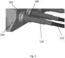
Fig. 2 shows a perspective view of the electrical connector inFig. 1 . - Referring to
Fig. 1 , anelectrical connector 100 for an aircraft is shown. Theelectrical connector 100 comprises a firstelectrical contact 102, a secondelectrical contact 104, ahousing 105, a first fixing element 106a and a second fixing element 106b. - In this embodiment, the first
electrical contact 102 is formed of a flat pin, wherein a surface of the flat pin comprises primary cut outs, the primary cut outs configured to receive thefixing elements 106. The firstelectrical contact 102 may be coated in a powder insulation layer, wherein the powder insulation layer comprises intervals, the intervals configured to allow the firstelectrical contact 102 to form electrical connections with the fixing elements 106a 106b and/or the second electrical contact 104 (e.g. with the intervals being portions where the powder insulation does not entirely cover the firstelectrical contact 102 such that an internal conductive portion of the firstelectrical contact 102 is exposed). - The second
electrical contact 104 is formed of a ring terminal, wherein the ring terminal comprises secondary cut outs, the secondary cut outs configured to receive thefixing elements 106. The secondelectrical contact 104 comprises acavity 112, wherein thecavity 112 is configured to receive the firstelectrical contact 102. The firstelectrical contact 102 is disposed in thecavity 112 to connect the firstelectrical contact 102 to the secondelectrical contact 104. This means a plurality of surfaces of the firstelectrical contact 102 may be in direct contact with the secondelectrical component 104 when the firstelectrical contact 102 and secondelectrical contact 104 are connected. In this embodiment, thecavity 112 is formed between two protruding portions, the secondelectrical contact 104 comprising the protruding portions. The protruding portions extend outwards from a centre of the ring terminal. The protruding portions extend in parallel to each other. The secondary cut outs are positioned on the protruding portions such that the fixing elements 106a 106b pass through both protruding portions when inserted. The firstelectrical contact 102 can be inserted in between the two protruding portions, such that the fixing elements 106a 106b pass through both protruding portions and the firstelectrical contact 102 when the fixing elements 106a 106b are inserted into theelectrical connector 100. - The first fixing element 106a and second fixing element 106b extend through the first
electrical contact 102 and the secondelectrical contact 104 to connect the firstelectrical contact 102 and the secondelectrical contact 104. When the firstelectrical contact 102 and secondelectrical contact 104 are connected, they are electrically coupled. In this embodiment, the fixing elements 106a 106b are screws. Theelectrical connector 100 further comprises athread locking component 122, wherein thethread locking component 122 is configured to prevent rotation of the fixing elements 106a 106b. In this embodiment, thethread locking components 122 are positioned on the secondelectrical contact 104, such that the first fixing element 106a and second fixing element 106b are fixed to the secondelectrical contact 104. In some embodiments, thethread locking component 122 may be an adhesive, such as a methacrylate-based fluid. - The second
electrical contact 104 is configured to receive anelectrical wire 110, such that the firstelectrical contact 102 and theelectrical wire 110 are electrically connected when theelectrical wire 110 is inserted into the secondelectrical contact 104. In some embodiments, crimping may be used to fix theelectrical wire 110 to the secondelectrical contact 104. The process of crimping comprises compressing a receiving portion of the secondelectrical contact 104, wherein the receiving portion contains theelectrical wire 110, such that an inner surface of the secondelectrical contact 104 presses against theelectrical wire 110. Theelectrical wire 110 therefore becomes electrically coupled with the secondelectrical connector 104 and theelectrical wire 110 is held in place by the inner surface of the secondelectrical contact 104. - The
housing 105 surrounds the firstelectrical contact 102 and secondelectrical contact 104. Thehousing 105 compriseselectrical insulation 107 to electrically insulate the firstelectrical contact 102 and secondelectrical contact 104 from an exterior of thehousing 105. Theelectrical insulation 107 comprises aninsulative layer 108 of thehousing 105. In this embodiment, theinsulative layer 108 comprises a ceramic material. - The
housing 105 further comprises acover 116 and an opening, wherein the opening is configured to permit access to the fixingelements 106. Thecover 116 is configured to close the opening. This means the fixing elements 106a 106b can be inserted or removed from theelectrical contacts 102 104 if thecover 116 is removed, for example if maintenance is required. - The
electrical connector 100 further comprises ashielding component 113. Theshielding component 113 is configured to shield theelectrical connector 100 from an exterior of theshielding component 113. This is achieved as theshielding component 113 is formed of electrically conductive materials connected to an electrical earthing point, therefore producing a conducting grounded shell around elements in an interior of theshielding component 113. Theshielding component 113 therefore prevents electromagnetic fields originating from the interior of theshielding component 113 reaching the exterior of theshielding component 113. Theshielding component 113 therefore also prevents electromagnetic signals from the exterior of theshielding component 113 from reaching the interior of theshielding component 113. These effects are beneficial as other components likely to be found near to theelectrical connector 100 on an aircraft may be affected by external electromagnetic signals. - The
shielding component 113 comprises acable shield 114, thecable shield 114 surrounding theelectrical wire 110. In this embodiment, thecable shield 114 comprises a conductive braid, wherein the conductive braid is wrapped around a surface of the electrical wire. The conductive braid runs along a length of theelectrical wire 110 to reach an earthing point. - The
shielding component 113 further comprises ashielding layer 115, wherein theshielding layer 115 forms part of thehousing 105, such that thehousing 105 provides shielding. In this embodiment, theshielding layer 115 is attached to theinsulative layer 108, such that it surrounds a portion of theelectrical connector 100. In some embodiments, theinsulative layer 108 may be formed on a surface of theshielding layer 115. Theshielding layer 115 may provide structure tohousing 105. The shielding layer may provide structure to theinsulative layer 108. A portion of theshielding layer 115 is exposed to electrically contact thecable shield 114. This permits electrical connection between theshielding layer 115 and thecable shield 114. This ensures theshielding component 113 is able to shield across the full length of the electrical connector, as the shielding effect is only achieved when a continuous conductive shell is formed. In this embodiment, theshielding layer 115 is formed of a layer of aluminium, wherein the layer of aluminium is positioned on an inner surface of theinsulative layer 108. - In this embodiment, the
cover 116 is abung 116. Thebung 116 comprises a conductive filling and an insulative body. Thebung 116 is positioned such that the conductive filling forms part of theshielding component 113, as the conductive filling is in electrical contact with theshielding layer 115. The conductive filling may be formed of aluminium. The insulative body forms parts of theelectrical insulation 107. The insulative body may be formed of silicon. - The
electrical connector 100 further comprises aclamp band 120. Theclamp band 120 may be formed of a ring-shaped body, wherein the ring-shaped body surrounds a portion of thehousing 105. Theclamp band 120 is configured to hold thecable shield 114 against a surface of thehousing 105. More specifically, theclamp band 120 is configured to hold thecable shield 114 against the exposed portion of theshielding layer 115 to ensure thecable shield 114 andshielding layer 115 remain in electrical contact. - The
electrical connector 100 further comprises aheatshrink layer 118. Theheatshrink layer 118 surrounds thehousing 105 andshielding component 113, such that theheatshrink layer 118 forms an outer surface of a portion of theelectrical connector 100. Theheatshrink layer 118 comprises a heatshrink material, wherein the heatshrink material is configured to tighten when heat is applied. Theheatshrink layer 118 therefore presses inward against thehousing 105 andshielding component 113 when heated during the installation of theheatshrink layer 118 onto theelectrical connector 100. This holds in place components of theelectrical connector 100 which are positioned in an interior of theheatshrink layer 118, whilst also providing an additional barrier from an exterior environment of theheatshrink layer 118. In some embodiments, theheatshrink layer 118 may have an adhesive backing, such that theheatshrink layer 118 can be fixed to the other components of the electrical connector 100.aterminal box 204. In some embodiments, theanchor point 202 may also be attached to thehousing 105. - In order to prepare the electrical connector for use, the
housing 105 is first placed over the firstelectrical contact 102. Theelectrical wire 110 is inserted into the secondelectrical contact 104 and crimped, such that the secondelectrical contact 104 and theelectrical wire 110 are connected. The firstelectrical connector 102 is then inserted into thecavity 112 of the secondelectrical connector 104, before the fixing elements 106a 106b are inserted through the firstelectrical contact 102 and secondelectrical contact 104. The fixing elements 106a 106b are inserted via the opening in thehousing 105. This means the firstelectrical contact 102, the secondelectrical contact 104 and theelectrical wire 110 are all electrically coupled. Thecover 116 is then inserted into the opening of the housing 105.Thecable shield 114 is wrapped around theelectrical wire 110, before theclamp band 120 is used to clamp thecable shield 114 to the exposed portion of theshielding layer 115. Theheatshrink layer 118 is then slid over the other components of theelectrical connector 100 before being heated, such that theheatshrink layer 118 tightens and holds the components of theelectrical connector 100 in place. - During use, the
electrical connector 100 is configured to transfer power to/from theterminal box 204 from/to an electrical device, wherein the electrical device is electrically connected to theelectrical wire 110. Theelectrical insulation 107 electrically insulates theelectrical connector 100. Theshielding component 113 provides shielding to theelectrical connector 100. - Various aspects disclosed in the various examples may be used alone, in combination, or in a variety of arrangements not specifically discussed in the examples described in the foregoing and this disclosure is therefore not limited in its application to the details and arrangement of components set forth in the foregoing description or illustrated in the drawings. For example, aspects described in one example may be combined in any manner with aspects described in other examples. Although particular examples have been shown and described, it will be obvious to those skilled in the art that changes and modifications may be made without departing from the invention in its broader aspects. The scope of the following claims should not be limited by the examples set forth in the examples, but should be given the broadest reasonable interpretation consistent with the description as a whole.
Claims (15)
- An electrical connector for an aircraft power system, the electrical connector comprising:a first electrical contact;a second electrical contact;a housing; anda fixing element, the fixing element extending through the first electrical contact and the second electrical contact to connect the first electrical contact to the second electrical contact,wherein the housing surrounds the first electrical contact and the second electrical contact, the housing comprising electrical insulation to electrically insulate the first and second electrical contacts from an exterior of the housing.
- The electrical connector of claim 1, wherein the second electrical contact is configured to receive an electrical wire, such that the first electrical contact and the electrical wire are electrically connected when the electrical wire is inserted into the second electrical contact.
- The electrical connector of any preceding claim, wherein the second electrical contact comprises a cavity, the first electrical contact disposed in the cavity to connect the first electrical contact to the second electrical contact.
- The electrical connector of any preceding claim, wherein the fixing element is a screw.
- The electrical connector of any preceding claim, wherein the electrical connector further comprises a thread locking component, the thread locking component configured to prevent rotation of the fixing element.
- The electrical connector of any preceding claim, wherein the housing comprises a cover and an opening, the opening configured to permit access to the fixing element, the cover configured to close the opening.
- The electrical connector of any preceding claim, wherein the electrical insulation comprises an insulative layer of the housing.
- The electrical connector of claim 7, wherein the insulative layer comprises a ceramic material.
- The electrical connector of any preceding claim, wherein the electrical connector further comprises a shielding component, the shielding component configured to shield the electrical connector from an exterior of the shielding component.
- The electrical connector of claim 9 when dependent on claim 2, wherein the shielding component comprises a cable shield, the cable shield surrounding the electrical wire.
- The electrical connector of claim 9 or 10, wherein the shielding component further comprises a shielding layer, the shielding layer forming part of the housing such that the housing provides shielding.
- The electrical connector of claim 11 when dependent on claim 10, wherein a portion of the shielding layer is exposed to electrically contact the cable shield to the shielding layer.
- A kit of parts for an electrical connector according to any preceding claim.
- An aircraft comprising an aircraft power system, the aircraft power system comprising an electric connector according to any of claims 1 to 12.
- An electrical terminal for an aircraft, the electrical terminal comprising:a first electrical contact;a housing; anda fixing element, wherein the fixing element is insertable into the first electrical contact to connect the first electrical contact to a second electrical contact,wherein the housing surrounds the first electrical contact and the second electrical contact when the first electrical contact and second electrical contact are connected to each other, the housing comprising electrical insulation to electrically insulate the first and second electrical contacts from an exterior of the housing.
Priority Applications (2)
| Application Number | Priority Date | Filing Date | Title |
|---|---|---|---|
| EP23208657.9A EP4554008A1 (en) | 2023-11-08 | 2023-11-08 | An electrical connector |
| US18/928,495 US20250149825A1 (en) | 2023-11-08 | 2024-10-28 | Electrical connector |
Applications Claiming Priority (1)
| Application Number | Priority Date | Filing Date | Title |
|---|---|---|---|
| EP23208657.9A EP4554008A1 (en) | 2023-11-08 | 2023-11-08 | An electrical connector |
Publications (1)
| Publication Number | Publication Date |
|---|---|
| EP4554008A1 true EP4554008A1 (en) | 2025-05-14 |
Family
ID=88745689
Family Applications (1)
| Application Number | Title | Priority Date | Filing Date |
|---|---|---|---|
| EP23208657.9A Pending EP4554008A1 (en) | 2023-11-08 | 2023-11-08 | An electrical connector |
Country Status (2)
| Country | Link |
|---|---|
| US (1) | US20250149825A1 (en) |
| EP (1) | EP4554008A1 (en) |
Citations (3)
| Publication number | Priority date | Publication date | Assignee | Title |
|---|---|---|---|---|
| US9040846B2 (en) * | 2011-06-29 | 2015-05-26 | Yazaki Corporation | Shielded cable fixing structure |
| US20180248275A1 (en) * | 2015-12-25 | 2018-08-30 | Fujikura Ltd. | Charging connector and method of manufacturing charging connector assembly |
| US11804663B2 (en) * | 2019-01-31 | 2023-10-31 | Autonetworks Technologies, Ltd. | Connector and connector connection structure |
-
2023
- 2023-11-08 EP EP23208657.9A patent/EP4554008A1/en active Pending
-
2024
- 2024-10-28 US US18/928,495 patent/US20250149825A1/en active Pending
Patent Citations (3)
| Publication number | Priority date | Publication date | Assignee | Title |
|---|---|---|---|---|
| US9040846B2 (en) * | 2011-06-29 | 2015-05-26 | Yazaki Corporation | Shielded cable fixing structure |
| US20180248275A1 (en) * | 2015-12-25 | 2018-08-30 | Fujikura Ltd. | Charging connector and method of manufacturing charging connector assembly |
| US11804663B2 (en) * | 2019-01-31 | 2023-10-31 | Autonetworks Technologies, Ltd. | Connector and connector connection structure |
Also Published As
| Publication number | Publication date |
|---|---|
| US20250149825A1 (en) | 2025-05-08 |
Similar Documents
| Publication | Publication Date | Title |
|---|---|---|
| US3567843A (en) | Electrical connector for waterproof jacketed armored cable | |
| EP2355260B1 (en) | Connector | |
| US3509518A (en) | High voltage cable connectors | |
| CN113826311B (en) | Installation of transmission units and transmission units with terminal box | |
| GB2353644A (en) | Connection structure for shielded cable | |
| US11804663B2 (en) | Connector and connector connection structure | |
| US20140144700A1 (en) | Oil-cooled equipment harness | |
| BR112018071935B1 (en) | HIGH VOLTAGE APPLIANCE AND MANUFACTURING METHOD OF SUCH APPLIANCE | |
| US3422392A (en) | Electrical bushing assembly | |
| CN101577154B (en) | High voltage bushing and high voltage device comprising such bushing | |
| US11536252B2 (en) | Down conductor connection system, wind turbine lightning protection system, and method for arranging a down conductor connection system | |
| US5646370A (en) | Permanent attachment of grounding wire | |
| CN100413163C (en) | Isolated phase bus duct joint assembly | |
| US12176690B2 (en) | High-voltage power distributor | |
| US3445580A (en) | Power cable termination with improved entrance system | |
| US20250149825A1 (en) | Electrical connector | |
| CN112952690A (en) | Electrical junction box and method of manufacture | |
| JP7307125B2 (en) | Water stop structure and water stop parts for shielded cables | |
| US3474393A (en) | High voltage cable terminal | |
| KR890003526B1 (en) | Gas insulated switchgear | |
| JP3181504B2 (en) | Power cable connection | |
| US3450827A (en) | Cable termination having stress relief means | |
| US20250329952A1 (en) | Compact generator terminal | |
| WO2022201493A1 (en) | Solid insulated bus and gas-insulated switchgear provided therewith | |
| JPS61137309A (en) | Gas insulated potential transformer |
Legal Events
| Date | Code | Title | Description |
|---|---|---|---|
| PUAI | Public reference made under article 153(3) epc to a published international application that has entered the european phase |
Free format text: ORIGINAL CODE: 0009012 |
|
| STAA | Information on the status of an ep patent application or granted ep patent |
Free format text: STATUS: THE APPLICATION HAS BEEN PUBLISHED |
|
| AK | Designated contracting states |
Kind code of ref document: A1 Designated state(s): AL AT BE BG CH CY CZ DE DK EE ES FI FR GB GR HR HU IE IS IT LI LT LU LV MC ME MK MT NL NO PL PT RO RS SE SI SK SM TR |
|
| STAA | Information on the status of an ep patent application or granted ep patent |
Free format text: STATUS: REQUEST FOR EXAMINATION WAS MADE |
|
| 17P | Request for examination filed |
Effective date: 20251113 |