EP4553988A1 - Electrode assembly, battery cell, battery, and electric device - Google Patents
Electrode assembly, battery cell, battery, and electric device Download PDFInfo
- Publication number
- EP4553988A1 EP4553988A1 EP23917094.7A EP23917094A EP4553988A1 EP 4553988 A1 EP4553988 A1 EP 4553988A1 EP 23917094 A EP23917094 A EP 23917094A EP 4553988 A1 EP4553988 A1 EP 4553988A1
- Authority
- EP
- European Patent Office
- Prior art keywords
- expansion layer
- separator
- electrode plate
- positive electrode
- battery
- Prior art date
- Legal status (The legal status is an assumption and is not a legal conclusion. Google has not performed a legal analysis and makes no representation as to the accuracy of the status listed.)
- Pending
Links
Images

Classifications
-
- H—ELECTRICITY
- H01—ELECTRIC ELEMENTS
- H01M—PROCESSES OR MEANS, e.g. BATTERIES, FOR THE DIRECT CONVERSION OF CHEMICAL ENERGY INTO ELECTRICAL ENERGY
- H01M50/00—Constructional details or processes of manufacture of the non-active parts of electrochemical cells other than fuel cells, e.g. hybrid cells
- H01M50/40—Separators; Membranes; Diaphragms; Spacing elements inside cells
- H01M50/409—Separators, membranes or diaphragms characterised by the material
- H01M50/411—Organic material
-
- H—ELECTRICITY
- H01—ELECTRIC ELEMENTS
- H01M—PROCESSES OR MEANS, e.g. BATTERIES, FOR THE DIRECT CONVERSION OF CHEMICAL ENERGY INTO ELECTRICAL ENERGY
- H01M10/00—Secondary cells; Manufacture thereof
- H01M10/05—Accumulators with non-aqueous electrolyte
- H01M10/054—Accumulators with insertion or intercalation of metals other than lithium, e.g. with magnesium or aluminium
-
- H—ELECTRICITY
- H01—ELECTRIC ELEMENTS
- H01M—PROCESSES OR MEANS, e.g. BATTERIES, FOR THE DIRECT CONVERSION OF CHEMICAL ENERGY INTO ELECTRICAL ENERGY
- H01M10/00—Secondary cells; Manufacture thereof
- H01M10/42—Methods or arrangements for servicing or maintenance of secondary cells or secondary half-cells
- H01M10/4235—Safety or regulating additives or arrangements in electrodes, separators or electrolyte
-
- H—ELECTRICITY
- H01—ELECTRIC ELEMENTS
- H01M—PROCESSES OR MEANS, e.g. BATTERIES, FOR THE DIRECT CONVERSION OF CHEMICAL ENERGY INTO ELECTRICAL ENERGY
- H01M4/00—Electrodes
- H01M4/02—Electrodes composed of, or comprising, active material
-
- H—ELECTRICITY
- H01—ELECTRIC ELEMENTS
- H01M—PROCESSES OR MEANS, e.g. BATTERIES, FOR THE DIRECT CONVERSION OF CHEMICAL ENERGY INTO ELECTRICAL ENERGY
- H01M4/00—Electrodes
- H01M4/02—Electrodes composed of, or comprising, active material
- H01M4/62—Selection of inactive substances as ingredients for active masses, e.g. binders, fillers
-
- H—ELECTRICITY
- H01—ELECTRIC ELEMENTS
- H01M—PROCESSES OR MEANS, e.g. BATTERIES, FOR THE DIRECT CONVERSION OF CHEMICAL ENERGY INTO ELECTRICAL ENERGY
- H01M50/00—Constructional details or processes of manufacture of the non-active parts of electrochemical cells other than fuel cells, e.g. hybrid cells
- H01M50/40—Separators; Membranes; Diaphragms; Spacing elements inside cells
-
- H—ELECTRICITY
- H01—ELECTRIC ELEMENTS
- H01M—PROCESSES OR MEANS, e.g. BATTERIES, FOR THE DIRECT CONVERSION OF CHEMICAL ENERGY INTO ELECTRICAL ENERGY
- H01M50/00—Constructional details or processes of manufacture of the non-active parts of electrochemical cells other than fuel cells, e.g. hybrid cells
- H01M50/40—Separators; Membranes; Diaphragms; Spacing elements inside cells
- H01M50/409—Separators, membranes or diaphragms characterised by the material
-
- H—ELECTRICITY
- H01—ELECTRIC ELEMENTS
- H01M—PROCESSES OR MEANS, e.g. BATTERIES, FOR THE DIRECT CONVERSION OF CHEMICAL ENERGY INTO ELECTRICAL ENERGY
- H01M50/00—Constructional details or processes of manufacture of the non-active parts of electrochemical cells other than fuel cells, e.g. hybrid cells
- H01M50/40—Separators; Membranes; Diaphragms; Spacing elements inside cells
- H01M50/409—Separators, membranes or diaphragms characterised by the material
- H01M50/411—Organic material
- H01M50/414—Synthetic resins, e.g. thermoplastics or thermosetting resins
-
- H—ELECTRICITY
- H01—ELECTRIC ELEMENTS
- H01M—PROCESSES OR MEANS, e.g. BATTERIES, FOR THE DIRECT CONVERSION OF CHEMICAL ENERGY INTO ELECTRICAL ENERGY
- H01M50/00—Constructional details or processes of manufacture of the non-active parts of electrochemical cells other than fuel cells, e.g. hybrid cells
- H01M50/40—Separators; Membranes; Diaphragms; Spacing elements inside cells
- H01M50/409—Separators, membranes or diaphragms characterised by the material
- H01M50/431—Inorganic material
-
- H—ELECTRICITY
- H01—ELECTRIC ELEMENTS
- H01M—PROCESSES OR MEANS, e.g. BATTERIES, FOR THE DIRECT CONVERSION OF CHEMICAL ENERGY INTO ELECTRICAL ENERGY
- H01M50/00—Constructional details or processes of manufacture of the non-active parts of electrochemical cells other than fuel cells, e.g. hybrid cells
- H01M50/40—Separators; Membranes; Diaphragms; Spacing elements inside cells
- H01M50/409—Separators, membranes or diaphragms characterised by the material
- H01M50/443—Particulate material
-
- H—ELECTRICITY
- H01—ELECTRIC ELEMENTS
- H01M—PROCESSES OR MEANS, e.g. BATTERIES, FOR THE DIRECT CONVERSION OF CHEMICAL ENERGY INTO ELECTRICAL ENERGY
- H01M50/00—Constructional details or processes of manufacture of the non-active parts of electrochemical cells other than fuel cells, e.g. hybrid cells
- H01M50/40—Separators; Membranes; Diaphragms; Spacing elements inside cells
- H01M50/409—Separators, membranes or diaphragms characterised by the material
- H01M50/446—Composite material consisting of a mixture of organic and inorganic materials
-
- H—ELECTRICITY
- H01—ELECTRIC ELEMENTS
- H01M—PROCESSES OR MEANS, e.g. BATTERIES, FOR THE DIRECT CONVERSION OF CHEMICAL ENERGY INTO ELECTRICAL ENERGY
- H01M50/00—Constructional details or processes of manufacture of the non-active parts of electrochemical cells other than fuel cells, e.g. hybrid cells
- H01M50/40—Separators; Membranes; Diaphragms; Spacing elements inside cells
- H01M50/409—Separators, membranes or diaphragms characterised by the material
- H01M50/449—Separators, membranes or diaphragms characterised by the material having a layered structure
-
- H—ELECTRICITY
- H01—ELECTRIC ELEMENTS
- H01M—PROCESSES OR MEANS, e.g. BATTERIES, FOR THE DIRECT CONVERSION OF CHEMICAL ENERGY INTO ELECTRICAL ENERGY
- H01M50/00—Constructional details or processes of manufacture of the non-active parts of electrochemical cells other than fuel cells, e.g. hybrid cells
- H01M50/40—Separators; Membranes; Diaphragms; Spacing elements inside cells
- H01M50/46—Separators, membranes or diaphragms characterised by their combination with electrodes
-
- H—ELECTRICITY
- H01—ELECTRIC ELEMENTS
- H01M—PROCESSES OR MEANS, e.g. BATTERIES, FOR THE DIRECT CONVERSION OF CHEMICAL ENERGY INTO ELECTRICAL ENERGY
- H01M50/00—Constructional details or processes of manufacture of the non-active parts of electrochemical cells other than fuel cells, e.g. hybrid cells
- H01M50/40—Separators; Membranes; Diaphragms; Spacing elements inside cells
- H01M50/489—Separators, membranes, diaphragms or spacing elements inside the cells, characterised by their physical properties, e.g. swelling degree, hydrophilicity or shut down properties
-
- H—ELECTRICITY
- H01—ELECTRIC ELEMENTS
- H01M—PROCESSES OR MEANS, e.g. BATTERIES, FOR THE DIRECT CONVERSION OF CHEMICAL ENERGY INTO ELECTRICAL ENERGY
- H01M50/00—Constructional details or processes of manufacture of the non-active parts of electrochemical cells other than fuel cells, e.g. hybrid cells
- H01M50/40—Separators; Membranes; Diaphragms; Spacing elements inside cells
- H01M50/489—Separators, membranes, diaphragms or spacing elements inside the cells, characterised by their physical properties, e.g. swelling degree, hydrophilicity or shut down properties
- H01M50/491—Porosity
-
- H—ELECTRICITY
- H01—ELECTRIC ELEMENTS
- H01M—PROCESSES OR MEANS, e.g. BATTERIES, FOR THE DIRECT CONVERSION OF CHEMICAL ENERGY INTO ELECTRICAL ENERGY
- H01M50/00—Constructional details or processes of manufacture of the non-active parts of electrochemical cells other than fuel cells, e.g. hybrid cells
- H01M50/40—Separators; Membranes; Diaphragms; Spacing elements inside cells
- H01M50/489—Separators, membranes, diaphragms or spacing elements inside the cells, characterised by their physical properties, e.g. swelling degree, hydrophilicity or shut down properties
- H01M50/494—Tensile strength
-
- H—ELECTRICITY
- H01—ELECTRIC ELEMENTS
- H01M—PROCESSES OR MEANS, e.g. BATTERIES, FOR THE DIRECT CONVERSION OF CHEMICAL ENERGY INTO ELECTRICAL ENERGY
- H01M50/00—Constructional details or processes of manufacture of the non-active parts of electrochemical cells other than fuel cells, e.g. hybrid cells
- H01M50/50—Current conducting connections for cells or batteries
- H01M50/572—Means for preventing undesired use or discharge
- H01M50/574—Devices or arrangements for the interruption of current
- H01M50/578—Devices or arrangements for the interruption of current in response to pressure
-
- H—ELECTRICITY
- H01—ELECTRIC ELEMENTS
- H01M—PROCESSES OR MEANS, e.g. BATTERIES, FOR THE DIRECT CONVERSION OF CHEMICAL ENERGY INTO ELECTRICAL ENERGY
- H01M50/00—Constructional details or processes of manufacture of the non-active parts of electrochemical cells other than fuel cells, e.g. hybrid cells
- H01M50/50—Current conducting connections for cells or batteries
- H01M50/572—Means for preventing undesired use or discharge
- H01M50/574—Devices or arrangements for the interruption of current
- H01M50/581—Devices or arrangements for the interruption of current in response to temperature
-
- H—ELECTRICITY
- H01—ELECTRIC ELEMENTS
- H01M—PROCESSES OR MEANS, e.g. BATTERIES, FOR THE DIRECT CONVERSION OF CHEMICAL ENERGY INTO ELECTRICAL ENERGY
- H01M50/00—Constructional details or processes of manufacture of the non-active parts of electrochemical cells other than fuel cells, e.g. hybrid cells
- H01M50/50—Current conducting connections for cells or batteries
- H01M50/572—Means for preventing undesired use or discharge
- H01M50/584—Means for preventing undesired use or discharge for preventing incorrect connections inside or outside the batteries
- H01M50/586—Means for preventing undesired use or discharge for preventing incorrect connections inside or outside the batteries inside the batteries, e.g. incorrect connections of electrodes
-
- H—ELECTRICITY
- H01—ELECTRIC ELEMENTS
- H01M—PROCESSES OR MEANS, e.g. BATTERIES, FOR THE DIRECT CONVERSION OF CHEMICAL ENERGY INTO ELECTRICAL ENERGY
- H01M2220/00—Batteries for particular applications
- H01M2220/20—Batteries in motive systems, e.g. vehicle, ship, plane
-
- Y—GENERAL TAGGING OF NEW TECHNOLOGICAL DEVELOPMENTS; GENERAL TAGGING OF CROSS-SECTIONAL TECHNOLOGIES SPANNING OVER SEVERAL SECTIONS OF THE IPC; TECHNICAL SUBJECTS COVERED BY FORMER USPC CROSS-REFERENCE ART COLLECTIONS [XRACs] AND DIGESTS
- Y02—TECHNOLOGIES OR APPLICATIONS FOR MITIGATION OR ADAPTATION AGAINST CLIMATE CHANGE
- Y02E—REDUCTION OF GREENHOUSE GAS [GHG] EMISSIONS, RELATED TO ENERGY GENERATION, TRANSMISSION OR DISTRIBUTION
- Y02E60/00—Enabling technologies; Technologies with a potential or indirect contribution to GHG emissions mitigation
- Y02E60/10—Energy storage using batteries
Definitions
- the present application relates to the field of battery technology, specifically to an electrode assembly, a battery cell, a battery, and an electrical device.
- batteries have become an indispensable energy source in industry and society.
- batteries have been increasingly widely used in fields such as electronic devices, electric vehicles, electric tools, and aerospace equipment.
- the demand for batteries in these fields is increasing, and the requirements for battery performance are also increasing.
- Safety performance is one of the important performance concerns in various application fields. Therefore, how to enable a battery to have good safety performance has become one of the urgent technical problems to be solved in the field of battery technology.
- the present application provides an electrode assembly, a battery cell, a battery, and an electrical device, where the electrode assembly enables the battery to have good safety performance.
- the present application provides an electrode assembly, including a positive electrode plate, a negative electrode plate, and a separator, where the separator is disposed between the positive electrode plate and the negative electrode plate; an expansion layer is disposed between the positive electrode plate and the negative electrode plate, and the expansion layer is configured for expanding in response to a preset condition to cut off an electrical connection between the positive electrode plate and the negative electrode plate.
- the expansion layer is provided between the positive electrode plate and the negative electrode plate; when the electrode assembly is applied to a battery, metal dendrites are produced inside the battery during use; the dendrites growing to a certain extent puncture the separator and electrically connect the positive electrode plate and the negative electrode plate to cause short circuits inside the battery, then the preset condition is satisfied, and the expansion layer expands in response to the preset condition to spread short-circuit points of the positive electrode plate and the negative electrode plate and wrap the dendrites at the short-circuit points, so that the electrical connection between the positive electrode plate and the negative electrode plate is cut off, the occurrence of thermal runaway inside the battery is reduced, and the battery has good safety performance.
- the preset condition includes a preset temperature and/or a preset pressure, which facilitates the expansion of the expansion layer to quickly cut off the electrical connection between the positive electrode plate and the negative electrode plate and further reduce the occurrence of thermal runaway inside the battery, thereby improving the safety performance of the battery.
- the preset condition includes a preset temperature, which is greater than or equal to 80°C, optionally 110°C to 150°C.
- the preset condition includes the preset temperature within the above range, which facilitates the expansion of the expansion layer in response to the preset condition to further reduce the occurrence of thermal runaway inside the battery, thereby further improving the safety performance of the battery.
- an expansion rate of the expansion layer in a thickness direction under the preset condition is 50% to 2000%, optionally 150% to 1000%.
- the expansion layer having the expansion rate within the above range can not only spread more short-circuit points, but also wrap more dendrites on the short-circuit points, to cut off more electrical connection points between the positive electrode plate and the negative electrode plate and further reduce the occurrence of thermal runaway inside the battery, thereby improving the safety performance of the battery.
- the expansion layer includes thermal expansion particles and a conductive agent, and based on a mass of the expansion layer, a mass ratio of the thermal expansion particles to the conductive agent is (1-6): 1.
- the expansion layer includes the thermal expansion particles and the conductive agent, and when the mass ratio of the thermal expansion particles to the conductive agent satisfies the above relationship, the occurrence of thermal runaway inside the battery can be reduced, and the resistance of the expansion layer can also be reduced, thereby improving the safety and cycle performance of the battery.
- a mass percentage of the thermal expansion particles in the expansion layer is 60% to 85%.
- the thermal runaway of the battery can be reduced, thereby improving the safety performance of the battery.
- a mass percentage of the conductive agent in the expansion layer is 15% to 35%.
- the resistance of the expansion layer can be reduced to improve the cycle performance of the battery.
- a material of the thermal expansion particles includes at least one of polyacrylonitrile, polymethacrylonitrile, N,N'-dimethyl-N,N'-dinitroso-p-terephthalamide, barium azodicarboxylate, or diisopropyl azodicarboxylate.
- the expansion layer further includes a preset temperature regulator, and a mass percentage of the preset temperature regulator in the expansion layer is 0.1% to 15%, optionally 0.5% to 10%.
- the expansion layer includes the preset temperature regulator, and when the mass percentage of the preset temperature regulator in the expansion layer is within the above range, the response sensitivity of the expansion layer can be improved to further improve the safety performance of the battery.
- the preset temperature regulator includes at least one of vinylidene chloride, acrylic ester, methacrylonitrile, sodium chloride, citric acid, or potassium dichromate.
- the expansion layer is disposed on a side of the negative electrode plate facing the separator.
- the expansion layer is disposed on a side of the positive electrode plate facing the separator.
- the expansion layer is disposed on a side of the separator.
- the expansion layer includes at least one of a stripe-like expansion layer, a netlike expansion layer, or a dotlikelike expansion layer.
- the expansion layer in the above shape can help improve the safety and cycle performance of the battery.
- the positive electrode plate includes a positive electrode current collector and a positive electrode active material layer, the positive electrode active material layer is disposed on a side of the positive electrode current collector and includes a positive electrode active material, and a thickness H1 of the expansion layer, a thickness H2 of the separator, and a thickness H3 of the positive electrode plate satisfy: ⁇ * H 1 + A * H 3 * ⁇ a / B / ⁇ b ⁇ H 2 where ⁇ represents the expansion rate of the expansion layer in the thickness direction under the preset condition, A represents a gram capacity of the positive electrode plate, ⁇ a represents a density of the positive electrode active material, B represents a gram capacity of sodium metal, and ⁇ b represents a density of sodium metal.
- the expansion layer after expansion can spread dendrites at short-circuit points of the positive electrode plate and the negative electrode plate, and can also reduce the probability that dendrites formed in other regions puncture the separator, thereby further improving the safety performance of the battery.
- ⁇ is 150% to 2000%; and/or A is 90 mAh/g to 150 mAh/g.
- the thickness H1 of the expansion layer is 0.1 ⁇ m to 10 ⁇ m.
- the thickness of the expansion layer within the above range enables the expansion layer after expansion to spread the dendrites at short-circuit points of the positive electrode plate and the negative electrode plate, and can further reduce the probability that the dendrites formed in other regions puncture the separator, thereby further improving the safety performance of the battery.
- the thickness H2 of the separator is 9 ⁇ m to 50 ⁇ m.
- the thickness of the separator within the above range can help reduce the probability that dendrites puncture the separator, which is beneficial to improving the safety performance of the battery.
- the thickness H3 of the positive electrode plate is 50 ⁇ m to 300 ⁇ m.
- the thickness of the positive electrode plate within the above range can help reduce the puncture of the separator by dendrites and improve the cycle performance of the battery.
- an air permeability of the separator is 120s/100cc to 180s/100cc.
- a puncture strength of the separator is 0.05 N/ ⁇ m to 0.5 N/ ⁇ m.
- an elongation of the separator at break is greater than or equal to 7%.
- a longitudinal tensile strength of the separator is greater than or equal to 120 MPa.
- a transverse tensile strength of the separator is greater than or equal to 10 MPa, optionally 20 MPa to 80 MPa.
- the separator includes a porous structure with a plurality of pores and has a porosity of 20% to 50%.
- the present application provides a battery cell, including the electrode assembly described in the first aspect of the present application.
- the present application provides a battery, including the battery cell in the second aspect of the present application.
- the present application provides an electrical device, including the battery in the third aspect of the present application.
- the term "and/or" in the present application is merely an association relationship for describing associated objects, and represents that three relationships may exist.
- a and/or B may represent the following three cases: A exists alone, both A and B exist, and B exists alone.
- the character "/" herein generally indicates an "or" relationship between successive associated objects.
- a plurality of means two (inclusive) or more.
- a plurality of groups means two (inclusive) or more groups, and "a plurality of pieces” means two (inclusive) or more pieces.
- an orientation or positional relationship indicated by the technical term “center”, “longitudinal”, “transverse”, “length”, “width”, “wall thickness”, “upper”, “lower”, “front”, “rear”, “left”, “right”, “vertical”, “horizontal”, “top”, “bottom”, “inner”, “outer”, “clockwise”, “counterclockwise”, “axial direction”, “radial direction”, “circumferential direction”, or the like is based on an orientation or positional relationship shown in the accompanying drawings, and is merely for ease of describing the embodiments of the present application and simplifying the description, but does not indicate or imply that an apparatus or an element referred to must have a specific orientation or be constructed and operated in a specific orientation, and therefore cannot be understood as a limitation on the embodiments of the present application.
- connection may be fixed connection, detachable connection, integration, mechanical connection, electrical connection, direct connection, indirect connection via an intermediate medium, internal communication between two elements, or interaction between two elements.
- a battery is mainly composed of one or more battery cells, each of which includes a shell, an end cover, and an electrode assembly accommodated in the shell, where the electrode assembly is a component that undergoes electrochemical reactions in the battery cell.
- the electrode assembly is mainly formed by winding or stacking a positive electrode plate and a negative electrode plate, and a separator is usually provided between the positive electrode plate and the negative electrode plate.
- the present application provides an electrode assembly, a battery cell, a battery, and an electrical device, where the electrode assembly enables the battery to have good safety performance.
- the present application provides an electrode assembly, including a positive electrode plate, a negative electrode plate, and a separator, where the separator is disposed between the positive electrode plate and the negative electrode plate; an expansion layer is disposed between the positive electrode plate and the negative electrode plate, and the expansion layer is used for expanding in response to a preset condition to cut off an electrical connection between the positive electrode plate and the negative electrode plate.
- the expansion layer is provided between the positive electrode plate and the negative electrode plate; when the electrode assembly is applied to a battery, metal dendrites are produced inside the battery during use; the dendrites growing to a certain extent puncture the separator and electrically connect the positive electrode plate and the negative electrode plate to cause short circuits inside the battery, then the preset condition is satisfied, and the expansion layer expands in response to the preset condition to spread short-circuit points of the positive electrode plate and the negative electrode plate and wrap the dendrites at the short-circuit points, so that the electrical connection between the positive electrode plate and the negative electrode plate is cut off, the occurrence of thermal runaway inside the battery is reduced, and the battery has good safety performance.
- the preset condition includes a preset temperature and/or a preset pressure.
- the preset condition includes the preset temperature and/or the preset pressure, which facilitates the expansion of the expansion layer to quickly cut off the electrical connection between the positive electrode plate and the negative electrode plate and further reduce the occurrence of thermal runaway inside the battery, thereby improving the safety performance of the battery.
- the preset condition includes a preset temperature, which is greater than or equal to 80°C, optionally 110°C to 150°C.
- the preset condition includes the preset temperature within the above range, which facilitates the expansion of the expansion layer in response to the preset condition to further reduce the occurrence of thermal runaway inside the battery, thereby further improving the safety performance of the battery.
- the preset temperature may be, but is not limited to, 80°C, 81°C, 82°C, 83°C, 84°C, 85°C, 86°C, 87°C, 88°C, 89°C, 90°C, 91°C, 92°C, 93°C, 94°C, 95°C, 96°C, 97°C, 98°C, 99°C, 100°C, 101°C, 102°C, 103°C, 104°C, 105°C, 106°C, 107°C, 108°C, 109°C, 110°C, 111°C, 112°C, 113°C, 114°C, 115°C, 116°C, 117°C, 118°C, 119°C, 120°C, 121°C, 122°C, 123°C, 124°C, 125°C 126°C, 127°C, 128°C, 129°C, 120
- an expansion rate of the expansion layer in a thickness direction under the preset condition is 50% to 2000%, optionally 150% to 1000%.
- the expansion layer having the expansion rate within the above range can not only spread more short-circuit points, but also wrap more dendrites on the short-circuit points, to cut off more electrical connection points between the positive electrode plate and the negative electrode plate and further reduce the occurrence of thermal runaway inside the battery, thereby improving the safety performance of the battery.
- the expansion rate refers to a ratio percentage of the difference in the thickness of a coating before and after expansion versus the thickness of the coating before expansion, and can be measured using a method well known in the art.
- the expansion rate can be measured by the following steps: taking a separator (1 cm ⁇ 1 cm) coated with an expansion layer, flushing residual electrolytic solution on its surface with anhydrous ethanol, then drying the separator in a vacuum drying oven at 45°C for 60 minutes, measuring the thickness Ha of the expansion layer in the cross-section of the separator using SEM, placing the separator at a trigger temperature of the expansion layer (such as 120°C), and standing for 30 minutes; then taking out and cooling the separator for 30 minutes, measuring the thickness Hb of the expansion layer in the cross-section of the separator using SEM, and calculating the expansion rate according to a formula that the expansion rate is equal to (Hb - Ha)/Ha ⁇ 100%.
- the expansion rate of the expansion layer in the thickness direction under the preset condition may be, but is not limited to, 50%, 100%, 150%, 200%, 250%, 300%, 350%, 400%, 450%, 500%, 550%, 600%, 650%, 700%, 750%, 800%, 850%, 900%, 950%, 1000%, 1050%, 1100%, 1150%, 1200%, 1250%, 1300%, 1350%, 1400%, 1450%, 1500%, 1550%, 1600%, 1650%, 1700%, 1750%, 1800%, 1850%, 1900%, 1950%, 2000%, or within a range consisting of any two of the above values, for example, the range of the expansion rate of the expansion layer in the thickness direction under the preset condition may be, but is not limited to, 100% to 1950%, 150% to 1800%, 250% to 1700%, 300% to 1600%, 400% to 1550%, 550% to 1400%, 600% to 1350%, or 700% to 1250%.
- the expansion layer includes thermal expansion particles and a conductive agent, and based on a mass of the expansion layer, a mass ratio of the thermal expansion particles to the conductive agent is (1-6): 1.
- the expansion layer includes the thermal expansion particles and the conductive agent, and when the mass ratio of the thermal expansion particles to the conductive agent satisfies the above relationship, the occurrence of thermal runaway inside the battery can be reduced, and the resistance of the expansion layer can also be reduced, thereby improving the safety and cycle performance of the battery.
- a mass percentage of the thermal expansion particles in the expansion layer is 60% to 85%.
- the thermal runaway of the battery can be reduced, thereby improving the safety performance of the battery.
- the mass percentage of the thermal expansion particles in the expansion layer may be, but is not limited to, 60%, 61%, 62%, 63%, 64%, 65%, 66%, 67%, 68%, 69%, 70%, 71%, 72%, 73%, 74%, 75%, 76%, 77%, 78%, 79%, 80%, 81%, 82%, 83%, 84%, 85%, or within a range consisting of any two of the above values, for example, the range of the mass percentage of the thermal expansion particles in the expansion layer may be 61% to 84%, 64% to 80%, or 67% to 76%.
- a mass percentage of the conductive agent in the expansion layer is 15% to 35%.
- the resistance of the expansion layer can be reduced to improve the cycle performance of the battery.
- the mass percentage of the conductive agent in the expansion layer may be, but is not limited to, 15%, 16%, 17%, 18%, 19%, 20%, 21%, 22%, 23%, 24%, 25%, 26%, 27%, 28%, 29%, 30%, 31%, 32%, 33%, 34%, 35%, or within a range consisting of any two of the above values, for example, the range of the mass percentage of the conductive agent in the expansion layer may be 16% to 34%, 18% to 32%, 20% to 30%, or 21% to 28%.
- a material of the thermal expansion particles includes at least one or polyacrylonitrile or polymethylacrylonitrile.
- the conductive agent may include at least one of graphite, superconducting carbon, acetylene black, carbon black, Ketjen black, carbon dots, carbon nanotubes, graphene, or carbon nanofibers.
- the expansion layer further includes a preset temperature regulator, and a mass percentage of the preset temperature regulator in the expansion layer is 0.1% to 15%, optionally 0.5% to 10%.
- the expansion layer includes the preset temperature regulator, and when the mass percentage of the preset temperature regulator in the expansion layer is within the above range, the response sensitivity of the expansion layer can be improved to further improve the safety performance of the battery.
- the mass percentage of the preset temperature regulator in the expansion layer may be, but is not limited to, 0.1%, 0.5%, 1%, 1.5%, 2%, 2.5%, 3%, 3.5%, 4%, 4.5%, 5%, 5.5%, 6%, 6.5%, 7%, 7.5%, 8%, 8.5%, 9%, 9.5%, 10%, 10.5%, 11%, 11.5%, 12%, 12.5%, 13%, 13.5%, 14%, 14.5%, 15%, or within a range consisting of any two of the above values, for example, the range of the mass percentage of the preset temperature regulator in the expansion layer may be, but is not limited to, 0.5% to 14.5%, 1% to 13.5%, 2% to 12%, 2.5% to 11.5%, 4% to 10.5%, 4.5% to 10%, or 5% to 9%.
- the preset temperature regulator includes at least one of vinylidene chloride, acrylic ester, methacrylonitrile, sodium chloride, citric acid, or potassium dichromate.
- the expansion layer further includes a hydrophilic polar monomer, which can help improve the puncture strength of the expansion layer and enables the expansion of the expansion layer to spread short-circuit points and wrap dendrites at the short-circuit points, thereby further improving the safety performance of the battery.
- the hydrophilic monomer may include, but is not limited to, monomers such as methyl methacrylate and acrylamide.
- the expansion layer is disposed on a side of the negative electrode plate facing the separator.
- the position of the expansion layer enables the expansion layer after expansion to quickly spread dendrites at short-circuit points, thereby reducing the occurrence of thermal runaway and improving the safety performance of the battery.
- the expansion layer is disposed on a side of the positive electrode plate facing the separator.
- the position of the expansion layer enables the expansion layer after expansion to wrap dendrites at short-circuit points, thereby cutting off the electrical connection between the positive electrode plate and the negative electrode plate to reduce the occurrence of thermal runaway and improving the safety performance of the battery.
- the expansion layer is disposed on a side of the separator.
- the position of the expansion layer enables the expansion layer after expansion to wrap dendrites at short-circuit points, thereby cutting off the electrical connection between the positive electrode plate and the negative electrode plate to reduce the occurrence of thermal runaway and improving the safety performance of the battery.
- the expansion layer includes at least one of a stripe-like expansion layer, a netlike expansion layer, or a dotlike expansion layer.
- the expansion layer in the above shape can help improve the safety and cycle performance of the battery.
- the expansion layer may include at least one of the netlike expansion layer, the dotlike expansion layer, or the stripe-like expansion layer, which is not limited by the embodiments of the present application.
- the shape of the expansion layer can be represented by a method well known in the art, for example, the shape of the expansion layer can be observed by scanning electron microscopy (SEM).
- the positive electrode plate includes a positive electrode current collector and a positive electrode active material layer disposed on a side of the positive electrode current collector and including a positive electrode active material, and a thickness H1 of the expansion layer, a thickness H2 of the separator, and a thickness H3 of the positive electrode plate satisfy: ⁇ * H 1 + A * H 3 * ⁇ a / B / ⁇ b ⁇ H 2 where ⁇ represents the expansion rate of the expansion layer in the thickness direction under the preset condition, A represents a gram capacity of the positive electrode plate, ⁇ a represents a density of the positive electrode active material, B represents a gram capacity of sodium metal, and ⁇ b represents a density of sodium metal.
- the sum of the thickness of the expansion layer after expansion and the length of formed sodium dendrites is less than or equal to the thickness of the separator, which enables the expansion layer after expansion to spread dendrites at short-circuit points of the positive electrode plate and the negative electrode plate, and can also reduce the probability that dendrites formed in other regions puncture the separator, thereby further improving the safety performance of the battery.
- the thickness of the expansion layer, the thickness of the separator, and the thickness of the positive electrode plate all have well-known meanings in the art and can be measured using methods well known in the art, such as a micrometer (such as Mitutoyo 293-100 model, with precision of 0.1 ⁇ m).
- ⁇ is 150% to 2000%; and/or A is 90 mAh/g to 150 mAh/g.
- ⁇ within the above range enables the expansion layer after expansion to spread the dendrites at short-circuit points of the positive electrode plate and the negative electrode plate.
- a within the above range can help reduce the length of dendrites, thereby reducing the puncture of the separator by the dendrites in contact with the expansion layer after the expansion layer expands, and further improving the safety performance of the battery.
- the thickness H1 of the expansion layer is 0.1 ⁇ m to 10 ⁇ m.
- the thickness of the expansion layer within the above range enables the expansion layer after expansion to spread the dendrites at short-circuit points of the positive electrode plate and the negative electrode plate, and can further reduce the probability that the dendrites formed in other regions puncture the separator, thereby further improving the safety performance of the battery.
- the thickness H2 of the separator is 9 ⁇ m to 50 ⁇ m.
- the thickness of the separator within the above range can help reduce the probability that dendrites puncture the separator, which is beneficial to improving the safety performance of the battery.
- the thickness H3 of the positive electrode plate is 50 ⁇ m to 300 ⁇ m.
- the thickness of the positive electrode plate within the above range can help reduce the puncture of the separator by dendrites and improve the cycle performance of the battery.
- an air permeability of the separator is 120s/100cc to 180s/100cc.
- the separator can have good air permeability, thereby improving ion transport characteristics and reducing battery resistance to improve the cycle performance of the battery.
- a puncture strength of the separator is 0.05 N/ ⁇ m to 0.5 N/ ⁇ m.
- an elongation of the separator at break is greater than or equal to 7%.
- a longitudinal tensile strength of the separator is greater than or equal to 120 MPa.
- a transverse tensile strength of the separator is greater than or equal to 10 MPa, optionally 20 MPa to 80 MPa.
- the air permeability, puncture strength, elongation at break, and tensile strengths of the separator all have meanings known in the art and can be measured using methods known in the art, for example, tested with reference to the standards GB/T 36363-2018.
- a surface density of the separator is 3 g/m 2 to 6 g/m 2 .
- the separator includes a porous structure with a plurality of pores and has a porosity of 20% to 50%.
- the porosity has a meaning known in the art, and refers to a ratio of a volume of pores in a material to a total volume of the material, and can be measured using instruments and methods known in the art.
- the material of the separator is not limited, and any known separator with good chemical and mechanical stability is available.
- the separator may include at least one of porous polyolefin resin films (such as one or more of polyethylene, polypropylene, and polyvinylidene fluoride), porous glass fibers, or porous non-woven fabrics.
- the porous separator may be a single-layer film or a multi-layer composite film. When the porous separator is a multi-layer composite film, the materials of the layers may be the same or different.
- the positive electrode plate includes a positive electrode current collector and a positive electrode active material layer disposed on a side of the positive electrode current collector and including a positive electrode active material.
- the embodiments of the present application do not limit the positive electrode current collector and the positive electrode active material, and can use positive electrode current collectors and positive electrode active materials known in the art.
- the positive electrode active material may include at least one of sodium transition metal oxides, polyanionic compounds, or Prussian blue compounds.
- other known materials can be used as positive electrode active materials for sodium-ion batteries.
- transition metals in the sodium transition metal oxides may include at least one of Mn, Fe, Ni, Co, Cr, Cu, Ti, Zn, V, Zr, or Ce.
- M when the sodium transition metal oxide is Na x MO 2 , M may be at least one of Ti, V, Mn, Co, Ni, Fe, Cr, or Cu, where 0 ⁇ x ⁇ 1.
- the polyanionic compounds may be a type of compounds with sodium ions, transition metal ions, and tetrahedral (YO 4 ) n- anion units, where transition metals may include at least one of Mn, Fe, Ni, Co, Cr, Cu, Ti, Zn, V, Zr, or Ce, Y may include at least one of P, S, or Si, where n represents a valence state of (YO 4 ) n- .
- the polyanionic compounds may alternatively be a type of compounds with sodium ions, transition metal ions, tetrahedral (YO 4 ) n- anion units, and halogen anions, where transition metals may include at least one of Mn, Fe, Ni, Co, Cr, Cu, Ti, Zn, V, Zr, or Ce, Y may include at least one of P, S, or Si, n represents a valence state of (YO 4 ) n- , and halogens may include at least one of F, Cl, or Br.
- transition metals may include at least one of Mn, Fe, Ni, Co, Cr, Cu, Ti, Zn, V, Zr, or Ce
- Y may include at least one of P, S, or Si
- n represents a valence state of (YO 4 ) n-
- halogens may include at least one of F, Cl, or Br.
- the polyanionic compounds may include at least one of NaFePO 4 , Na 3 V 2 (PO 4 ) 3 , NaM'PO 4 F (M' includes at least one of V, Fe, Mn, or Ni), or Na 3 (VO y ) 2 (PO 4 ) 2 F 3-2y (0 ⁇ y ⁇ 1).
- the Prussian blue compounds may be a type of compounds with sodium ions, transition metal ions, and cyanide ions (CN - ).
- Transition metals may be at least one of Mn, Fe, Ni, Co, Cr, Cu, Ti, Zn, V, Zr, or Ce.
- the Prussian blue compounds may be, for example, Na a Me b Me' c (CN) 6 , where Me and Me' respectively include at least one of Ni, Cu, Fe, Mn, Co, or Zn, where 0 ⁇ a ⁇ 2, 0 ⁇ b ⁇ 1, and 0 ⁇ c ⁇ 1.
- the positive electrode active material layer may further include a conductive agent and a binder.
- the embodiments of the present application do not specifically limit the types of the conductive agent and the binder in the positive electrode active material layer, which can be selected according to actual needs.
- the conductive agent may be, but is not limited to, at least one of graphite, superconducting carbon, acetylene black, carbon black, Ketjen black, carbon dots, carbon nanotubes, graphene, or carbon nanofibers;
- the binder may be, but is not limited to, at least one of styrene butadiene rubber (SBR), waterborne acrylic resin, carboxymethyl cellulose (CMC), polyvinylidene fluoride (PVDF), polytetrafluoroethylene (PTFE), polyvinyl butyral (PVB), ethylene-vinyl acetate copolymer (EVA), vinylidene fluoride-tetrafluoroethylene-propylene terpolymer, vinylidene fluoride-hexafluoropropylene-tetrafluoroethylene terpolymer, tetrafluoroethylene-hexafluoropropylene copolymer, fluorinated acrylic resin, or polyvinyl alcohol
- the positive electrode current collector may be made of a material such as a metal foil or a porous metal plate.
- the material of the positive electrode current collector may be, but is not limited to, a foil or porous plate made of metals such as copper, nickel, titanium, silver, or alloys thereof.
- an aluminum foil is used as the positive electrode current collector.
- the positive electrode active material, the conductive agent, and the binder are thoroughly stirred and mixed in an appropriate amount of N-methylpyrrolidone (NMP) at a certain mass ratio to form a uniform positive electrode slurry; the positive electrode slurry is applied to the surface of the positive electrode current collector aluminum foil, and the positive electrode plate is obtained after drying, cold pressing, and die cutting.
- NMP N-methylpyrrolidone
- the negative electrode plate includes a negative electrode current collector.
- the negative electrode current collector may be made of a material with electronic conductivity.
- the material of the negative electrode current collector may be a copper foil, a nickel foil, a stainless steel foil, etc.
- the negative electrode plate may further include a negative electrode active material layer disposed on one side of the negative electrode current collector and including a negative electrode active material, but the type of the negative electrode active material is not limited and can be selected by those skilled in the art according to actual needs.
- the negative electrode active material may include at least one of carbon materials, alloy materials, transition metal oxides, transition metal sulfides, phosphorus-based materials, or titanate materials.
- the negative electrode active material includes carbon materials.
- the carbon materials may include at least one of natural graphite, artificial graphite, mesocarbon microbeads (MCMB), hard carbon, or soft carbon.
- the alloy materials may include at least one of alloy materials composed of Si, Ge, Sn, Pb, and Sb.
- the phosphorus-based materials may include at least one of red phosphorus, white phosphorus, or black phosphorus.
- the titanate materials may include at least one of Na 2 Ti 3 O 7 , Na 2 Ti 6 O 13 , Na 4 Ti 5 O 12 , Li 4 Ti 5 O 12 , or NaTi 2 (PO 4 ) 3 .
- the negative electrode active material layer may further include a conductive agent and a binder.
- the embodiments of the present application do not specifically limit the types of the conductive agent and the binder in the negative electrode active material layer, which can be selected according to actual needs.
- the conductive agent may be, but is not limited to, at least one of graphite, superconducting carbon, acetylene black, carbon black, Ketjen black, carbon dots, carbon nanotubes, graphene, or carbon nanofibers;
- the binder may be, but is not limited to, at least one of styrene butadiene rubber (SBR), polyvinylidene fluoride (PVDF), polytetrafluoroethylene (PTFE), polyvinyl butyral (PVB), waterborne acrylic resin, or carboxymethyl cellulose (CMC).
- SBR styrene butadiene rubber
- PVDF polyvinylidene fluoride
- PTFE polytetrafluoroethylene
- PVB polyvinyl butyral
- waterborne acrylic resin or carboxymethyl cellulose (CMC).
- the negative electrode active material, the conductive agent, and the binder are mixed in a certain mass ratio and thoroughly stirred in an appropriate amount of deionized water to form a uniform negative electrode slurry; the negative electrode slurry is applied to the surface of the negative electrode current collector, and the negative electrode plate is obtained after drying, cold pressing, and die cutting.
- the electrode assembly may be produced using methods known in the art, for example, the positive electrode plate, the separator, and the negative electrode plate may be wound and/or stacked to form the electrode assembly, where at least one of the positive electrode plate, the separator, and the negative electrode plate is coated with the expansion layer.
- the present application provides a battery cell, including the electrode assembly as described in the first aspect of the present application.
- the battery cell further includes an electrolyte, and the electrolyte includes an organic solvent and an electrolyte sodium salt.
- the types of the electrolyte sodium salt and the organic solvent are not specifically limited and can be selected according to actual needs.
- the electrolyte may include an organic solvent and an electrolyte sodium salt.
- the organic solvent includes ether organic solvents
- the ether organic solvents include at least one of diethylene glycol dimethyl ether, triethylene glycol dimethyl ether, tetraethylene glycol dimethyl ether, or tetrahydrofuran.
- a molar concentration of the electrolyte sodium salt in the electrolyte is 0.5 mol/L to 3 mol/L
- the electrolyte sodium salt may include at least one of sodium hexafluorophosphate, sodium fluoroborate, sodium bis(trifluoromethanesulfonyl) imide, sodium bis(fluorosulfonyl) imide, or sodium oxalate borate.
- the electrolyte may further optionally include additives.
- the additives may include a negative electrode film-forming additive, a positive electrode film-forming additive, and additives that can improve some performance of the battery cell, such as an additive that improves the overcharge performance of the battery cell, an additive that improves the high-temperature performance of the battery cell, and an additive that improves the low-temperature power performance of the battery cell.
- the battery cell may further include an outer package.
- the outer package can be used for packing the aforementioned electrode assembly and electrolyte.
- the outer package of the battery cell may be a hard shell, such as a hard plastic shell, an aluminum shell, or a steel shell.
- the outer package of the battery cell may alternatively be a soft package, such as a pouch type soft package.
- the material of the soft package may be plastic, such as at least one of polypropylene (PP), polybutylene terephthalate (PBT), and polybutylene succinate (PBS).
- the present application does not limit the shape of the battery cell.
- the battery cell may be in a cylindrical, square, or any other shape.
- Fig. 1 shows a square battery cell 5 as an example.
- the outer package may include a shell 51 and a cover plate 53.
- the shell 51 may include a bottom plate and side plates connected to the bottom plate, and the bottom plate and the side plates enclose an accommodating cavity.
- the shell 51 has an opening in communication with the accommodating cavity, and the cover plate 53 is closed to the opening to seal the accommodating cavity.
- the positive electrode plate, the negative electrode plate, and the separator may be wound and/or stacked to form an electrode assembly 52.
- the electrode assembly 52 is packaged in the accommodating cavity.
- An electrolyte infiltrates the electrode assembly 52.
- the battery cell 5 may include at least one electrode assemblies 52, which may be adjusted according to a demand.
- the positive electrode plate, the separator, the negative electrode plate, and the electrolyte may be assembled to form the battery cell.
- the positive electrode plate, the separator, the expansion layer, and the negative electrode plate may be wound and/or stacked to form the electrode assembly, the electrode assembly is placed in the outer package, the electrolyte is injected after drying, and the battery cell is obtained after vacuum packaging, standing, chemical transformation, shaping, etc.
- the present application provides a battery, including the battery cell in the second aspect of the present application.
- the battery in order to meet different power requirements, may include a plurality of battery cells, which refer to minimum units that constitute a battery module or battery pack.
- the plurality of battery cells may be connected in series and/or in parallel via electrode terminals for various applications.
- the battery mentioned in the embodiments of the present application includes a battery module or battery pack.
- the plurality of battery cells may be connected in series, in parallel, or in series and parallel.
- the series and parallel connection refers to a combination of series connection and parallel connection.
- the plurality of battery cells may be directly combined into a battery pack, or may be first combined into a battery module, which then forms a battery pack.
- the battery cell according to the second aspect of the present application may be assembled into a battery module, the battery module may include a plurality of battery cells, and the specific quantity can be adjusted according to the application and capacity of the battery module.
- Fig. 3 is a schematic structural view of a battery module as an example.
- the plurality of battery cells 5 may be arranged sequentially in a length direction of the battery module 4.
- the battery cells may be arranged in any other manner.
- the plurality of battery cells 5 may be fixed by fasteners.
- the battery module 4 may further include a housing with an accommodating space, and the plurality of battery cells 5 are accommodated in the accommodating space.
- the battery module can be assembled into a battery pack, and the quantity of battery modules included in the battery pack can be adjusted according to the application and capacity of the battery pack.
- Fig. 4 and Fig. 5 are schematic structural views of a battery pack as an example.
- the battery pack 1 may include a battery box and a plurality of battery modules 4 disposed in the battery box.
- the battery box includes an upper box 2 and a lower box 3.
- the upper box 2 fits on the lower box 3 to form a closed space for accommodating the battery modules 4.
- the plurality of battery modules 4 may be arranged in the battery box in any manner.
- the present application provides an electrical device, which includes at least one of the battery cell, the battery module, or the battery pack in the second aspect of the present application.
- the battery cell, the battery module, or the battery pack may be used as a power supply for the electrical device or as an energy storage unit of the electrical device.
- the electrical device may include, but is not limited to, a mobile phone, a tablet, a laptop, an electric toy, an electric tool, a scooter, an electric vehicle, a ship, a spacecraft, an energy storage system, etc.
- the electric toy may include a fixed or mobile electric toy, such as a game console, an electric car toy, an electric ship toy, or an electric aircraft toy.
- the spacecraft may include an airplane, a rocket, a space shuttle, a spaceship, etc.
- the electrical device may include the battery cell, battery module, or battery pack according to its usage requirements.
- Fig. 6 is a schematic structural view of an electrical device as an example.
- the electrical device is a full electric vehicle, a hybrid electric vehicle, a plug-in hybrid electric vehicle, or the like.
- the battery pack or the battery module may be used.
- a positive electrode active material NaMnKFe(CN) 6 , a conductive agent acetylene black, and a binder carboxymethyl cellulose were thoroughly stirred and mixed in an appropriate amount of N-methylpyrrolidone (NMP) at a mass ratio of 95: 2: 3 to form a uniform positive electrode slurry; the positive electrode slurry was applied to the surface of a positive electrode current collector aluminum foil, and a positive electrode plate having a thickness of 175 ⁇ m was obtained after drying, cold pressing, and die cutting.
- NMP N-methylpyrrolidone
- a negative electrode active material artificial graphite, a conductive agent acetylene black, and a binder carboxymethyl cellulose were mixed in a mass ratio of 94: 5: 1 and thoroughly stirred in an appropriate amount of deionized water to form a uniform negative electrode slurry; the negative electrode slurry was applied to the surface of a negative electrode current collector copper foil, and a negative electrode plate was obtained after drying, cold pressing, and die cutting.
- a polyethylene film having a thickness of 9 ⁇ m was used.
- Thermal expansion polymethacrylonitrile particles and a binder carboxymethyl cellulose were mixed in a mass ratio of 1.86: 1 to form a slurry; the slurry was applied to the side of the separator facing the negative electrode plate, and dried to form an expansion layer having a thickness of 1 ⁇ m.
- Ethylene carbonate, sodium hexafluorophosphate, and boron-containing additives were mixed in a mass ratio of 85: 10: 5 to obtain a sodium salt electrolyte.
- the positive electrode plate, the separator coated with the expansion layer, and the negative electrode plate were wound and/or stacked to form an electrode assembly, the electrode assembly was placed in an outer package, the electrolyte was injected after drying, and a sodium-ion secondary battery was obtained after vacuum packaging, standing, chemical transformation, shaping, etc.
- a separator (1 cm ⁇ 1 cm) coated with an expansion layer was taken, residual electrolyte on its surface was flushed with anhydrous ethanol, then the separator was placed in a vacuum drying oven at 45°C and dried for 60 minutes, the thickness Ha of the expansion layer in the cross-section of the separator was measured using SEM, and the separator was placed at a trigger temperature of the expansion layer (such as 120°C), and stood for 30 minutes; then the separator was taken out and cooled for 30 minutes, the thickness Hb of the expansion layer in the cross-section of the separator was measured using SEM, and the expansion rate was calculated according to a formula that the expansion rate is equal to (Hb - Ha)/Ha ⁇ 100%.
- 40 batteries were taken from the same batch, stood at 25°C for 2 hours, discharged at a rate of 0.33C to a rated voltage of 1.5V, and stood for 2 hours.
- the batteries were charged with a constant current of 1C to a rated voltage of 4.2V, then the capacity of the batteries was 100% SOC, and the charging capacity was C1.
- the batteries were continuously charged with 1C to a capacity of 0.4C1, and the batteries were overcharged to 140% SOC.
- Table 1 lists relevant parameters and test results of the expansion layer in Examples 1-10 and Comparative Example 1, respectively.
- Table 1 Expansion layer Preset temperature Expansion rate Failure rate Number Material of thermal expansion particles, mass% Binder, mass %
- Example 1 Polymethacrylonitrile 65% 35% 110°C 210% 62.5%
- Example 2 Polymethacrylonitrile 69% 31% 110°C 250% 55%
- Example 3 Polymethacrylonitrile 75% 25% 110°C 280% 50%
- Example 4 Polymethacrylonitrile 79% 21% 110°C 320% 42.5%
- Example 5 Polymethacrylonitrile 85% 15% 110°C 360% 37.5%
- Example 6 Polyacrylonitrile 75% 25% 140°C 160% 67.5%
- Example 7 Barium azodicarboxylate 75% 25% 130°C 400% 32.5%
- Example 8 Diisopropyl azodicarboxylate 75% 25% 120°C 860% 27.5%
- Example 9 N,N'-dimethyl-N
Landscapes
- Chemical & Material Sciences (AREA)
- Chemical Kinetics & Catalysis (AREA)
- Electrochemistry (AREA)
- General Chemical & Material Sciences (AREA)
- Engineering & Computer Science (AREA)
- Materials Engineering (AREA)
- Manufacturing & Machinery (AREA)
- Inorganic Chemistry (AREA)
- Composite Materials (AREA)
- Secondary Cells (AREA)
- Cell Separators (AREA)
- Battery Electrode And Active Subsutance (AREA)
Abstract
Description
- The present application claims priority to
Chinese patent application No. 202310075434.7, entitled "ELECTRODE ASSEMBLY, BATTERY CELL, BATTERY, AND ELECTRICAL DEVICE" filed on January 16, 2023 - The present application relates to the field of battery technology, specifically to an electrode assembly, a battery cell, a battery, and an electrical device.
- As a new energy source, batteries have become an indispensable energy source in industry and society. With the development of battery technology, batteries have been increasingly widely used in fields such as electronic devices, electric vehicles, electric tools, and aerospace equipment. The demand for batteries in these fields is increasing, and the requirements for battery performance are also increasing. Safety performance is one of the important performance concerns in various application fields. Therefore, how to enable a battery to have good safety performance has become one of the urgent technical problems to be solved in the field of battery technology.
- The present application provides an electrode assembly, a battery cell, a battery, and an electrical device, where the electrode assembly enables the battery to have good safety performance.
- In a first aspect, the present application provides an electrode assembly, including a positive electrode plate, a negative electrode plate, and a separator, where the separator is disposed between the positive electrode plate and the negative electrode plate; an expansion layer is disposed between the positive electrode plate and the negative electrode plate, and the expansion layer is configured for expanding in response to a preset condition to cut off an electrical connection between the positive electrode plate and the negative electrode plate.
- In the electrode assembly provided in the present application, the expansion layer is provided between the positive electrode plate and the negative electrode plate; when the electrode assembly is applied to a battery, metal dendrites are produced inside the battery during use; the dendrites growing to a certain extent puncture the separator and electrically connect the positive electrode plate and the negative electrode plate to cause short circuits inside the battery, then the preset condition is satisfied, and the expansion layer expands in response to the preset condition to spread short-circuit points of the positive electrode plate and the negative electrode plate and wrap the dendrites at the short-circuit points, so that the electrical connection between the positive electrode plate and the negative electrode plate is cut off, the occurrence of thermal runaway inside the battery is reduced, and the battery has good safety performance.
- According to any of the foregoing embodiments in the first aspect of the present application, the preset condition includes a preset temperature and/or a preset pressure, which facilitates the expansion of the expansion layer to quickly cut off the electrical connection between the positive electrode plate and the negative electrode plate and further reduce the occurrence of thermal runaway inside the battery, thereby improving the safety performance of the battery.
- According to any of the foregoing embodiments in the first aspect of the present application, the preset condition includes a preset temperature, which is greater than or equal to 80°C, optionally 110°C to 150°C. The preset condition includes the preset temperature within the above range, which facilitates the expansion of the expansion layer in response to the preset condition to further reduce the occurrence of thermal runaway inside the battery, thereby further improving the safety performance of the battery.
- According to any of the foregoing embodiments in the first aspect of the present application, an expansion rate of the expansion layer in a thickness direction under the preset condition is 50% to 2000%, optionally 150% to 1000%. The expansion layer having the expansion rate within the above range can not only spread more short-circuit points, but also wrap more dendrites on the short-circuit points, to cut off more electrical connection points between the positive electrode plate and the negative electrode plate and further reduce the occurrence of thermal runaway inside the battery, thereby improving the safety performance of the battery.
- According to any of the foregoing embodiments in the first aspect of the present application, the expansion layer includes thermal expansion particles and a conductive agent, and based on a mass of the expansion layer, a mass ratio of the thermal expansion particles to the conductive agent is (1-6): 1. The expansion layer includes the thermal expansion particles and the conductive agent, and when the mass ratio of the thermal expansion particles to the conductive agent satisfies the above relationship, the occurrence of thermal runaway inside the battery can be reduced, and the resistance of the expansion layer can also be reduced, thereby improving the safety and cycle performance of the battery.
- According to any of the foregoing embodiments in the first aspect of the present application, a mass percentage of the thermal expansion particles in the expansion layer is 60% to 85%. When the mass percentage of the thermal expansion particles in the expansion layer is within the above range, the thermal runaway of the battery can be reduced, thereby improving the safety performance of the battery.
- According to any of the foregoing embodiments in the first aspect of the present application, a mass percentage of the conductive agent in the expansion layer is 15% to 35%. When the mass percentage of the conductive agent in the expansion layer is within the above range, the resistance of the expansion layer can be reduced to improve the cycle performance of the battery.
- According to any of the foregoing embodiments in the first aspect of the present application, a material of the thermal expansion particles includes at least one of polyacrylonitrile, polymethacrylonitrile, N,N'-dimethyl-N,N'-dinitroso-p-terephthalamide, barium azodicarboxylate, or diisopropyl azodicarboxylate.
- According to any of the foregoing embodiments in the first aspect of the present application, the expansion layer further includes a preset temperature regulator, and a mass percentage of the preset temperature regulator in the expansion layer is 0.1% to 15%, optionally 0.5% to 10%. The expansion layer includes the preset temperature regulator, and when the mass percentage of the preset temperature regulator in the expansion layer is within the above range, the response sensitivity of the expansion layer can be improved to further improve the safety performance of the battery.
- According to any of the foregoing embodiments in the first aspect of the present application, the preset temperature regulator includes at least one of vinylidene chloride, acrylic ester, methacrylonitrile, sodium chloride, citric acid, or potassium dichromate.
- According to any of the foregoing embodiments in the first aspect of the present application, the expansion layer is disposed on a side of the negative electrode plate facing the separator.
- According to any of the foregoing embodiments in the first aspect of the present application, the expansion layer is disposed on a side of the positive electrode plate facing the separator.
- According to any of the foregoing embodiments in the first aspect of the present application, the expansion layer is disposed on a side of the separator.
- According to any of the foregoing embodiments in the first aspect of the present application, the expansion layer includes at least one of a stripe-like expansion layer, a netlike expansion layer, or a dotlikelike expansion layer. The expansion layer in the above shape can help improve the safety and cycle performance of the battery.
- According to any of the foregoing embodiments in the first aspect of the present application, the positive electrode plate includes a positive electrode current collector and a positive electrode active material layer, the positive electrode active material layer is disposed on a side of the positive electrode current collector and includes a positive electrode active material, and a thickness H1 of the expansion layer, a thickness H2 of the separator, and a thickness H3 of the positive electrode plate satisfy:

- According to any of the foregoing embodiments in the first aspect of the present application, α is 150% to 2000%; and/or A is 90 mAh/g to 150 mAh/g.
- According to any of the foregoing embodiments in the first aspect of the present application, the thickness H1 of the expansion layer is 0.1 µm to 10 µm. The thickness of the expansion layer within the above range enables the expansion layer after expansion to spread the dendrites at short-circuit points of the positive electrode plate and the negative electrode plate, and can further reduce the probability that the dendrites formed in other regions puncture the separator, thereby further improving the safety performance of the battery.
- According to any of the foregoing embodiments in the first aspect of the present application, the thickness H2 of the separator is 9 µm to 50 µm. The thickness of the separator within the above range can help reduce the probability that dendrites puncture the separator, which is beneficial to improving the safety performance of the battery.
- According to any of the foregoing embodiments in the first aspect of the present application, the thickness H3 of the positive electrode plate is 50 µm to 300 µm. The thickness of the positive electrode plate within the above range can help reduce the puncture of the separator by dendrites and improve the cycle performance of the battery.
- According to any of the foregoing embodiments in the first aspect of the present application, an air permeability of the separator is 120s/100cc to 180s/100cc.
- According to any of the foregoing embodiments in the first aspect of the present application, a puncture strength of the separator is 0.05 N/µm to 0.5 N/µm.
- According to any of the foregoing embodiments in the first aspect of the present application, an elongation of the separator at break is greater than or equal to 7%.
- According to any of the foregoing embodiments in the first aspect of the present application, a longitudinal tensile strength of the separator is greater than or equal to 120 MPa.
- According to any of the foregoing embodiments in the first aspect of the present application, a transverse tensile strength of the separator is greater than or equal to 10 MPa, optionally 20 MPa to 80 MPa.
- According to any of the foregoing embodiments in the first aspect of the present application, a surface density of the separator is 3 g/m2 to 6 g/m2.
- According to any of the foregoing embodiments in the first aspect of the present application, the separator includes a porous structure with a plurality of pores and has a porosity of 20% to 50%.
- In a second aspect, the present application provides a battery cell, including the electrode assembly described in the first aspect of the present application.
- In a third aspect, the present application provides a battery, including the battery cell in the second aspect of the present application.
- In a fourth aspect, the present application provides an electrical device, including the battery in the third aspect of the present application.
- The above description is only a summary of the technical solutions of the present application. In order to understand the technical means in the present application more clearly, it can be implemented in accordance with the content of the description; and in order to make the above and other objectives, features and advantages of the present application more obvious and easier to understand, specific embodiments of the present application are cited below.
- By reading the detailed description of optional embodiments below, various other advantages and benefits will become clear to those skilled in the art. The accompanying drawings are only used for illustrating the optional embodiments and are not considered as limitations on the present application. Moreover, in all the drawings, the same reference numerals denote the same components.
-
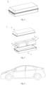
Fig. 1 illustrates a schematic structural view of a battery cell provided in some embodiments of the present application. -
Fig. 2 illustrates an exploded view of the battery cell inFig. 1 . -
Fig. 3 illustrates a schematic structural view of a battery module provided in some embodiments of the present application. -
Fig. 4 illustrates a schematic structural view of a battery pack provided in some embodiments of the present application. -
Fig. 5 illustrates an exploded view of the battery pack inFig. 4 . -
Fig. 6 illustrates a schematic structural view of an electrical device provided in some embodiments of the present application. - The accompanying drawings are not drawn to actual scale. Reference numerals are described as follows:
1 - battery pack, 2 - upper box, 3 - lower box, 4 - battery module, 5 - battery cell, 51 - shell, 52 - electrode assembly, 53 - cover plate. - The embodiments of the technical solutions of the present application will be described in detail below with reference to the accompanying drawings. The following embodiments are only used for illustrating the technical solutions of the present application more clearly, and therefore are only examples with no intention of limiting the protection scope of the present application.
- Unless otherwise defined, all technical and scientific terms used herein have the same meanings as those commonly understood by technical personnel in the technical field of the present application; the terms used herein are only for the purpose of describing specific embodiments and are not intended to limit the present application; and the terms "include" and "have" in the description and claims of the present application, the above accompanying drawings, and any variations thereof, are intended to cover non-exclusive inclusion.
- In the description of the embodiments of the present application, the technical terms "first", "second", and the like are only used for distinguishing different objects and cannot be understood as indicating or implying relative importance or implying a quantity, specific order, or primary and secondary relationship of the indicated technical features. In the description of the embodiments of the present application, the meaning of "a plurality of" is two or more, unless otherwise specifically defined.
- The phrase "embodiment" referred to herein means that specific features, structures, or characteristics described in conjunction with the embodiment may be included in at least one embodiment of the present application. The phrase appearing at various places in the description does not necessarily refer to the same embodiment, or an independent or alternative embodiment exclusive of other embodiments. Those skilled in the art understand explicitly and implicitly that an embodiment described herein may be combined with another embodiment.
- In the description of the embodiments of the present application, the term "and/or" in the present application is merely an association relationship for describing associated objects, and represents that three relationships may exist. For example, A and/or B may represent the following three cases: A exists alone, both A and B exist, and B exists alone. In addition, the character "/" herein generally indicates an "or" relationship between successive associated objects.
- In the description of the embodiments of the present application, the term "a plurality of" means two (inclusive) or more. Similarly, "a plurality of groups" means two (inclusive) or more groups, and "a plurality of pieces" means two (inclusive) or more pieces.
- In the description of the embodiments of the present application, an orientation or positional relationship indicated by the technical term "center", "longitudinal", "transverse", "length", "width", "wall thickness", "upper", "lower", "front", "rear", "left", "right", "vertical", "horizontal", "top", "bottom", "inner", "outer", "clockwise", "counterclockwise", "axial direction", "radial direction", "circumferential direction", or the like is based on an orientation or positional relationship shown in the accompanying drawings, and is merely for ease of describing the embodiments of the present application and simplifying the description, but does not indicate or imply that an apparatus or an element referred to must have a specific orientation or be constructed and operated in a specific orientation, and therefore cannot be understood as a limitation on the embodiments of the present application.
- In the description of the embodiments of the present application, unless otherwise explicitly specified and defined, the technical terms "mounted", "connected", "connection", "fixed", etc. should be understood in a broad sense, for example, the "connection" may be fixed connection, detachable connection, integration, mechanical connection, electrical connection, direct connection, indirect connection via an intermediate medium, internal communication between two elements, or interaction between two elements. Those of ordinary skill in the art may appreciate the specific meanings of the foregoing terms in the embodiments of the present application according to specific circumstances.
- In the present application, a battery is mainly composed of one or more battery cells, each of which includes a shell, an end cover, and an electrode assembly accommodated in the shell, where the electrode assembly is a component that undergoes electrochemical reactions in the battery cell. Specifically, the electrode assembly is mainly formed by winding or stacking a positive electrode plate and a negative electrode plate, and a separator is usually provided between the positive electrode plate and the negative electrode plate.
- In the charging and discharging process of the battery, metal ions deposit unevenly on the surface of the negative electrode plate. As the number of charging and discharging cycles of the battery increases, dendrites will form. When the dendrites overgrow and puncture the separator, the positive electrode plate and the negative electrode plate may be short-circuited, and even the risk such as fire or explosion may occur, resulting in a decline in the safety performance of the battery.
- In view of this, the present application provides an electrode assembly, a battery cell, a battery, and an electrical device, where the electrode assembly enables the battery to have good safety performance.
- In a first aspect, the present application provides an electrode assembly, including a positive electrode plate, a negative electrode plate, and a separator, where the separator is disposed between the positive electrode plate and the negative electrode plate; an expansion layer is disposed between the positive electrode plate and the negative electrode plate, and the expansion layer is used for expanding in response to a preset condition to cut off an electrical connection between the positive electrode plate and the negative electrode plate.
- In the electrode assembly provided in the present application, the expansion layer is provided between the positive electrode plate and the negative electrode plate; when the electrode assembly is applied to a battery, metal dendrites are produced inside the battery during use; the dendrites growing to a certain extent puncture the separator and electrically connect the positive electrode plate and the negative electrode plate to cause short circuits inside the battery, then the preset condition is satisfied, and the expansion layer expands in response to the preset condition to spread short-circuit points of the positive electrode plate and the negative electrode plate and wrap the dendrites at the short-circuit points, so that the electrical connection between the positive electrode plate and the negative electrode plate is cut off, the occurrence of thermal runaway inside the battery is reduced, and the battery has good safety performance.
- In some embodiments of the present application, the preset condition includes a preset temperature and/or a preset pressure. The preset condition includes the preset temperature and/or the preset pressure, which facilitates the expansion of the expansion layer to quickly cut off the electrical connection between the positive electrode plate and the negative electrode plate and further reduce the occurrence of thermal runaway inside the battery, thereby improving the safety performance of the battery.
- In some embodiments of the present application, the preset condition includes a preset temperature, which is greater than or equal to 80°C, optionally 110°C to 150°C. The preset condition includes the preset temperature within the above range, which facilitates the expansion of the expansion layer in response to the preset condition to further reduce the occurrence of thermal runaway inside the battery, thereby further improving the safety performance of the battery.
- In some examples, the preset temperature may be, but is not limited to, 80°C, 81°C, 82°C, 83°C, 84°C, 85°C, 86°C, 87°C, 88°C, 89°C, 90°C, 91°C, 92°C, 93°C, 94°C, 95°C, 96°C, 97°C, 98°C, 99°C, 100°C, 101°C, 102°C, 103°C, 104°C, 105°C, 106°C, 107°C, 108°C, 109°C, 110°C, 111°C, 112°C, 113°C, 114°C, 115°C, 116°C, 117°C, 118°C, 119°C, 120°C, 121°C, 122°C, 123°C, 124°C, 125°C 126°C, 127°C, 128°C, 129°C, 130°C, 131°C, 132°C, 133°C, 134°C, 135°C, 136°C, 137°C, 138°C, 139°C, 140°C, 141°C, 142°C, 143°C, 144°C, 145°C, 146°C, 147°C, 148°C, 149°C, 150°C, or within a range consisting of any two of the above values, for example, the range of the preset temperature may be, but is not limited to, 81°C to 148°C, 85°C to 145°C, 88°C to 140°C, 92°C to 134°C, 95°C to 130°C, 99°C to 125°C, or 102°C to 120°C.
- In some embodiments of the present application, an expansion rate of the expansion layer in a thickness direction under the preset condition is 50% to 2000%, optionally 150% to 1000%. The expansion layer having the expansion rate within the above range can not only spread more short-circuit points, but also wrap more dendrites on the short-circuit points, to cut off more electrical connection points between the positive electrode plate and the negative electrode plate and further reduce the occurrence of thermal runaway inside the battery, thereby improving the safety performance of the battery.
- In the present application, the expansion rate refers to a ratio percentage of the difference in the thickness of a coating before and after expansion versus the thickness of the coating before expansion, and can be measured using a method well known in the art. For example, the expansion rate can be measured by the following steps: taking a separator (1 cm × 1 cm) coated with an expansion layer, flushing residual electrolytic solution on its surface with anhydrous ethanol, then drying the separator in a vacuum drying oven at 45°C for 60 minutes, measuring the thickness Ha of the expansion layer in the cross-section of the separator using SEM, placing the separator at a trigger temperature of the expansion layer (such as 120°C), and standing for 30 minutes; then taking out and cooling the separator for 30 minutes, measuring the thickness Hb of the expansion layer in the cross-section of the separator using SEM, and calculating the expansion rate according to a formula that the expansion rate is equal to (Hb - Ha)/Ha × 100%.
- In some examples, the expansion rate of the expansion layer in the thickness direction under the preset condition may be, but is not limited to, 50%, 100%, 150%, 200%, 250%, 300%, 350%, 400%, 450%, 500%, 550%, 600%, 650%, 700%, 750%, 800%, 850%, 900%, 950%, 1000%, 1050%, 1100%, 1150%, 1200%, 1250%, 1300%, 1350%, 1400%, 1450%, 1500%, 1550%, 1600%, 1650%, 1700%, 1750%, 1800%, 1850%, 1900%, 1950%, 2000%, or within a range consisting of any two of the above values, for example, the range of the expansion rate of the expansion layer in the thickness direction under the preset condition may be, but is not limited to, 100% to 1950%, 150% to 1800%, 250% to 1700%, 300% to 1600%, 400% to 1550%, 550% to 1400%, 600% to 1350%, or 700% to 1250%.
- In some embodiments of the present application, the expansion layer includes thermal expansion particles and a conductive agent, and based on a mass of the expansion layer, a mass ratio of the thermal expansion particles to the conductive agent is (1-6): 1. The expansion layer includes the thermal expansion particles and the conductive agent, and when the mass ratio of the thermal expansion particles to the conductive agent satisfies the above relationship, the occurrence of thermal runaway inside the battery can be reduced, and the resistance of the expansion layer can also be reduced, thereby improving the safety and cycle performance of the battery.
- In some embodiments of the present application, a mass percentage of the thermal expansion particles in the expansion layer is 60% to 85%. When the mass percentage of the thermal expansion particles in the expansion layer is within the above range, the thermal runaway of the battery can be reduced, thereby improving the safety performance of the battery.
- In some examples, the mass percentage of the thermal expansion particles in the expansion layer may be, but is not limited to, 60%, 61%, 62%, 63%, 64%, 65%, 66%, 67%, 68%, 69%, 70%, 71%, 72%, 73%, 74%, 75%, 76%, 77%, 78%, 79%, 80%, 81%, 82%, 83%, 84%, 85%, or within a range consisting of any two of the above values, for example, the range of the mass percentage of the thermal expansion particles in the expansion layer may be 61% to 84%, 64% to 80%, or 67% to 76%.
- In some embodiments of the present application, a mass percentage of the conductive agent in the expansion layer is 15% to 35%. When the mass percentage of the conductive agent in the expansion layer is within the above range, the resistance of the expansion layer can be reduced to improve the cycle performance of the battery.
- In some examples, the mass percentage of the conductive agent in the expansion layer may be, but is not limited to, 15%, 16%, 17%, 18%, 19%, 20%, 21%, 22%, 23%, 24%, 25%, 26%, 27%, 28%, 29%, 30%, 31%, 32%, 33%, 34%, 35%, or within a range consisting of any two of the above values, for example, the range of the mass percentage of the conductive agent in the expansion layer may be 16% to 34%, 18% to 32%, 20% to 30%, or 21% to 28%.
- In some embodiments of the present application, a material of the thermal expansion particles includes at least one or polyacrylonitrile or polymethylacrylonitrile.
- In some embodiments of the present application, the conductive agent may include at least one of graphite, superconducting carbon, acetylene black, carbon black, Ketjen black, carbon dots, carbon nanotubes, graphene, or carbon nanofibers.
- In some embodiments of the present application, the expansion layer further includes a preset temperature regulator, and a mass percentage of the preset temperature regulator in the expansion layer is 0.1% to 15%, optionally 0.5% to 10%. The expansion layer includes the preset temperature regulator, and when the mass percentage of the preset temperature regulator in the expansion layer is within the above range, the response sensitivity of the expansion layer can be improved to further improve the safety performance of the battery.
- In some examples, the mass percentage of the preset temperature regulator in the expansion layer may be, but is not limited to, 0.1%, 0.5%, 1%, 1.5%, 2%, 2.5%, 3%, 3.5%, 4%, 4.5%, 5%, 5.5%, 6%, 6.5%, 7%, 7.5%, 8%, 8.5%, 9%, 9.5%, 10%, 10.5%, 11%, 11.5%, 12%, 12.5%, 13%, 13.5%, 14%, 14.5%, 15%, or within a range consisting of any two of the above values, for example, the range of the mass percentage of the preset temperature regulator in the expansion layer may be, but is not limited to, 0.5% to 14.5%, 1% to 13.5%, 2% to 12%, 2.5% to 11.5%, 4% to 10.5%, 4.5% to 10%, or 5% to 9%.
- In some embodiments of the present application, the preset temperature regulator includes at least one of vinylidene chloride, acrylic ester, methacrylonitrile, sodium chloride, citric acid, or potassium dichromate.
- In other embodiments of the present application, the expansion layer further includes a hydrophilic polar monomer, which can help improve the puncture strength of the expansion layer and enables the expansion of the expansion layer to spread short-circuit points and wrap dendrites at the short-circuit points, thereby further improving the safety performance of the battery.
- In some examples, the hydrophilic monomer may include, but is not limited to, monomers such as methyl methacrylate and acrylamide.
- In some embodiments of the present application, the expansion layer is disposed on a side of the negative electrode plate facing the separator. The position of the expansion layer enables the expansion layer after expansion to quickly spread dendrites at short-circuit points, thereby reducing the occurrence of thermal runaway and improving the safety performance of the battery.
- In some embodiments of the present application, the expansion layer is disposed on a side of the positive electrode plate facing the separator. The position of the expansion layer enables the expansion layer after expansion to wrap dendrites at short-circuit points, thereby cutting off the electrical connection between the positive electrode plate and the negative electrode plate to reduce the occurrence of thermal runaway and improving the safety performance of the battery.
- In some embodiments of the present application, the expansion layer is disposed on a side of the separator. The position of the expansion layer enables the expansion layer after expansion to wrap dendrites at short-circuit points, thereby cutting off the electrical connection between the positive electrode plate and the negative electrode plate to reduce the occurrence of thermal runaway and improving the safety performance of the battery.
- In some embodiments of the present application, the expansion layer includes at least one of a stripe-like expansion layer, a netlike expansion layer, or a dotlike expansion layer. The expansion layer in the above shape can help improve the safety and cycle performance of the battery.
- It can be understood that the expansion layer may include at least one of the netlike expansion layer, the dotlike expansion layer, or the stripe-like expansion layer, which is not limited by the embodiments of the present application.
- In the present application, the shape of the expansion layer can be represented by a method well known in the art, for example, the shape of the expansion layer can be observed by scanning electron microscopy (SEM).
- In some embodiments of the present application, the positive electrode plate includes a positive electrode current collector and a positive electrode active material layer disposed on a side of the positive electrode current collector and including a positive electrode active material, and a thickness H1 of the expansion layer, a thickness H2 of the separator, and a thickness H3 of the positive electrode plate satisfy:

where α represents the expansion rate of the expansion layer in the thickness direction under the preset condition, A represents a gram capacity of the positive electrode plate, ρa represents a density of the positive electrode active material, B represents a gram capacity of sodium metal, and ρb represents a density of sodium metal. - It can be understood that the sum of the thickness of the expansion layer after expansion and the length of formed sodium dendrites is less than or equal to the thickness of the separator, which enables the expansion layer after expansion to spread dendrites at short-circuit points of the positive electrode plate and the negative electrode plate, and can also reduce the probability that dendrites formed in other regions puncture the separator, thereby further improving the safety performance of the battery.
- In the present application, the thickness of the expansion layer, the thickness of the separator, and the thickness of the positive electrode plate all have well-known meanings in the art and can be measured using methods well known in the art, such as a micrometer (such as Mitutoyo 293-100 model, with precision of 0.1 µm).
- In some embodiments of the present application, α is 150% to 2000%; and/or A is 90 mAh/g to 150 mAh/g. α within the above range enables the expansion layer after expansion to spread the dendrites at short-circuit points of the positive electrode plate and the negative electrode plate. A within the above range can help reduce the length of dendrites, thereby reducing the puncture of the separator by the dendrites in contact with the expansion layer after the expansion layer expands, and further improving the safety performance of the battery.
- In some embodiments of the present application, the thickness H1 of the expansion layer is 0.1 µm to 10 µm. The thickness of the expansion layer within the above range enables the expansion layer after expansion to spread the dendrites at short-circuit points of the positive electrode plate and the negative electrode plate, and can further reduce the probability that the dendrites formed in other regions puncture the separator, thereby further improving the safety performance of the battery.
- In some examples, the thickness of the expansion layer may be, but is not limited to, 0.1 µm, 0.5 µm, 1 µm, 1.5 µm, 2 µm, 2.5 µm, 3 µm, 3.5 µm, 4 µm, 4.5 µm, 5 µm, 5.5 µm, 6 µm, 6.5 µm, 7 µm, 7.5 µm, 8 µm, 8.5 µm, 9 µm, 9.5 µm, 10 µm, or within a range consisting of any two of the above values, for example, the range of the thickness of the expansion layer may be, but is not limited to, 0.5 µm to 9.5 µm, 1 µm to 9 µm, 1.5 µm to 8.5 µm, 2 µm to 8 µm, 2.5 µm to 7.5 µm, or 3 µm to 6.5 µm.
- In some embodiments of the present application, the thickness H2 of the separator is 9 µm to 50 µm. The thickness of the separator within the above range can help reduce the probability that dendrites puncture the separator, which is beneficial to improving the safety performance of the battery.
- In some examples, the thickness of the separator may be, but is not limited to, 9 µm, 10 µm, 11 µm, 12 µm, 13 µm, 14 µm, 15 µm, 16 µm, 17 µm, 18 µm, 19 µm, 20 µm, 21 µm, 22 µm, 23 µm, 24 µm, 25 µm, 26 µm, 27 µm, 28 µm, 29 µm, 30 µm, 31 µm, 32 µm, 33 µm, 34 µm, 35 µm, 36 µm, 37 µm, 38 µm, 39 µm, 40 µm, 41 µm, 42 µm, 43 µm, 44 µm, 45 µm, 46 µm, 47 µm, 48 µm, 49 µm, 50 µm, or within a range consisting of any two of the above values, for example, the range of the thickness of the separator may be, but is not limited to, 10 µm to 48 µm, 13 µm to 45 µm, 15 µm to 41 µm, 18 µm to 38 µm, 20 µm to 36 µm, 23 µm to 33 µm, or 25 µm to 31 µm.
- In some embodiments of the present application, the thickness H3 of the positive electrode plate is 50 µm to 300 µm. The thickness of the positive electrode plate within the above range can help reduce the puncture of the separator by dendrites and improve the cycle performance of the battery.
- In some embodiments of the present application, an air permeability of the separator is 120s/100cc to 180s/100cc. When the air permeability of the separator is within the above range, the separator can have good air permeability, thereby improving ion transport characteristics and reducing battery resistance to improve the cycle performance of the battery.
- In some embodiments of the present application, a puncture strength of the separator is 0.05 N/µm to 0.5 N/µm.
- In some embodiments of the present application, an elongation of the separator at break is greater than or equal to 7%.
- In some embodiments of the present application, a longitudinal tensile strength of the separator is greater than or equal to 120 MPa.
- In some embodiments of the present application, a transverse tensile strength of the separator is greater than or equal to 10 MPa, optionally 20 MPa to 80 MPa.
- In the present application, the air permeability, puncture strength, elongation at break, and tensile strengths of the separator all have meanings known in the art and can be measured using methods known in the art, for example, tested with reference to the standards GB/T 36363-2018.
- In some embodiments of the present application, a surface density of the separator is 3 g/m2 to 6 g/m2.
- In some embodiments of the present application, the separator includes a porous structure with a plurality of pores and has a porosity of 20% to 50%.
- In the present application, the porosity has a meaning known in the art, and refers to a ratio of a volume of pores in a material to a total volume of the material, and can be measured using instruments and methods known in the art. For example, with reference to the national standards GB/T 24586-2009 in which the apparent density, true density, and porosity of iron ore can be measured, the porosity can be tested using the AccuPyc II 1340 fully automatic true density tester from Micromeritics in the United States. Porosity = (V1 - V2)/ V1 * 100%, where V1 refers to an apparent volume of a material and V2 refers to a true volume of the material. V1 can be tested using a mercury intrusion method, and V2 can be tested using a nitrogen gas adsorption method.
- In the embodiments of the present application, the material of the separator is not limited, and any known separator with good chemical and mechanical stability is available. For example, the separator may include at least one of porous polyolefin resin films (such as one or more of polyethylene, polypropylene, and polyvinylidene fluoride), porous glass fibers, or porous non-woven fabrics. The porous separator may be a single-layer film or a multi-layer composite film. When the porous separator is a multi-layer composite film, the materials of the layers may be the same or different.
- In some embodiments of the present application, the positive electrode plate includes a positive electrode current collector and a positive electrode active material layer disposed on a side of the positive electrode current collector and including a positive electrode active material. The embodiments of the present application do not limit the positive electrode current collector and the positive electrode active material, and can use positive electrode current collectors and positive electrode active materials known in the art.
- In some embodiments of the present application, the positive electrode active material may include at least one of sodium transition metal oxides, polyanionic compounds, or Prussian blue compounds. In other embodiments of the present application, other known materials can be used as positive electrode active materials for sodium-ion batteries.
- In some examples, transition metals in the sodium transition metal oxides may include at least one of Mn, Fe, Ni, Co, Cr, Cu, Ti, Zn, V, Zr, or Ce. For example, when the sodium transition metal oxide is NaxMO2, M may be at least one of Ti, V, Mn, Co, Ni, Fe, Cr, or Cu, where 0 < x ≤ 1.
- In other examples, the polyanionic compounds may be a type of compounds with sodium ions, transition metal ions, and tetrahedral (YO4)n- anion units, where transition metals may include at least one of Mn, Fe, Ni, Co, Cr, Cu, Ti, Zn, V, Zr, or Ce, Y may include at least one of P, S, or Si, where n represents a valence state of (YO4)n-.
- The polyanionic compounds may alternatively be a type of compounds with sodium ions, transition metal ions, tetrahedral (YO4)n- anion units, and halogen anions, where transition metals may include at least one of Mn, Fe, Ni, Co, Cr, Cu, Ti, Zn, V, Zr, or Ce, Y may include at least one of P, S, or Si, n represents a valence state of (YO4)n-, and halogens may include at least one of F, Cl, or Br.
- In some specific embodiments, the polyanionic compounds may include at least one of NaFePO4, Na3V2(PO4)3, NaM'PO4F (M' includes at least one of V, Fe, Mn, or Ni), or Na3(VOy)2(PO4)2F3-2y (0 ≤ y ≤ 1).
- In some examples, the Prussian blue compounds may be a type of compounds with sodium ions, transition metal ions, and cyanide ions (CN-). Transition metals may be at least one of Mn, Fe, Ni, Co, Cr, Cu, Ti, Zn, V, Zr, or Ce. The Prussian blue compounds may be, for example, NaaMebMe'c(CN)6, where Me and Me' respectively include at least one of Ni, Cu, Fe, Mn, Co, or Zn, where 0 < a ≤ 2, 0 < b < 1, and 0 < c < 1.
- In some embodiments of the present application, the positive electrode active material layer may further include a conductive agent and a binder. The embodiments of the present application do not specifically limit the types of the conductive agent and the binder in the positive electrode active material layer, which can be selected according to actual needs.
- For example, the conductive agent may be, but is not limited to, at least one of graphite, superconducting carbon, acetylene black, carbon black, Ketjen black, carbon dots, carbon nanotubes, graphene, or carbon nanofibers; the binder may be, but is not limited to, at least one of styrene butadiene rubber (SBR), waterborne acrylic resin, carboxymethyl cellulose (CMC), polyvinylidene fluoride (PVDF), polytetrafluoroethylene (PTFE), polyvinyl butyral (PVB), ethylene-vinyl acetate copolymer (EVA), vinylidene fluoride-tetrafluoroethylene-propylene terpolymer, vinylidene fluoride-hexafluoropropylene-tetrafluoroethylene terpolymer, tetrafluoroethylene-hexafluoropropylene copolymer, fluorinated acrylic resin, or polyvinyl alcohol (PVA).
- In some embodiments of the present application, the positive electrode current collector may be made of a material such as a metal foil or a porous metal plate. For example, the material of the positive electrode current collector may be, but is not limited to, a foil or porous plate made of metals such as copper, nickel, titanium, silver, or alloys thereof. Further, in some specific embodiments of the present application, an aluminum foil is used as the positive electrode current collector.
- In the embodiments of the present application, the positive electrode active material, the conductive agent, and the binder are thoroughly stirred and mixed in an appropriate amount of N-methylpyrrolidone (NMP) at a certain mass ratio to form a uniform positive electrode slurry; the positive electrode slurry is applied to the surface of the positive electrode current collector aluminum foil, and the positive electrode plate is obtained after drying, cold pressing, and die cutting.
- In some embodiments of the present application, the negative electrode plate includes a negative electrode current collector. In some examples, the negative electrode current collector may be made of a material with electronic conductivity. For example, the material of the negative electrode current collector may be a copper foil, a nickel foil, a stainless steel foil, etc.
- In some embodiments of the present application, the negative electrode plate may further include a negative electrode active material layer disposed on one side of the negative electrode current collector and including a negative electrode active material, but the type of the negative electrode active material is not limited and can be selected by those skilled in the art according to actual needs. For example, the negative electrode active material may include at least one of carbon materials, alloy materials, transition metal oxides, transition metal sulfides, phosphorus-based materials, or titanate materials. In some specific embodiments, the negative electrode active material includes carbon materials.
- In some examples, the carbon materials may include at least one of natural graphite, artificial graphite, mesocarbon microbeads (MCMB), hard carbon, or soft carbon. The alloy materials may include at least one of alloy materials composed of Si, Ge, Sn, Pb, and Sb. A chemical formula of the transition metal oxides is, for example, M1 uOv, where M1 may be at least one of Fe, Co, Ni, Cu, Mn, Sn, Mo, Sb, or V, au=2v, and a is a valence state of M1. A chemical formula of the transition metal sulfides is, for example, M2 iSj, where M2 may include at least one of Fe, Co, Ni, Cu, Mn, Sn, Mo, Sb, or V, bi=2j, and b is a valence state of M2. The phosphorus-based materials may include at least one of red phosphorus, white phosphorus, or black phosphorus. The titanate materials may include at least one of Na2Ti3O7, Na2Ti6O13, Na4Ti5O12, Li4Ti5O12, or NaTi2(PO4)3.
- In some embodiments of the present application, the negative electrode active material layer may further include a conductive agent and a binder. The embodiments of the present application do not specifically limit the types of the conductive agent and the binder in the negative electrode active material layer, which can be selected according to actual needs.
- For example, the conductive agent may be, but is not limited to, at least one of graphite, superconducting carbon, acetylene black, carbon black, Ketjen black, carbon dots, carbon nanotubes, graphene, or carbon nanofibers; the binder may be, but is not limited to, at least one of styrene butadiene rubber (SBR), polyvinylidene fluoride (PVDF), polytetrafluoroethylene (PTFE), polyvinyl butyral (PVB), waterborne acrylic resin, or carboxymethyl cellulose (CMC).
- In the embodiments of the present application, the negative electrode active material, the conductive agent, and the binder are mixed in a certain mass ratio and thoroughly stirred in an appropriate amount of deionized water to form a uniform negative electrode slurry; the negative electrode slurry is applied to the surface of the negative electrode current collector, and the negative electrode plate is obtained after drying, cold pressing, and die cutting.
- In the embodiments of the present application, the electrode assembly may be produced using methods known in the art, for example, the positive electrode plate, the separator, and the negative electrode plate may be wound and/or stacked to form the electrode assembly, where at least one of the positive electrode plate, the separator, and the negative electrode plate is coated with the expansion layer.
- In a second aspect, the present application provides a battery cell, including the electrode assembly as described in the first aspect of the present application.
- In some embodiments of the present application, the battery cell further includes an electrolyte, and the electrolyte includes an organic solvent and an electrolyte sodium salt. The types of the electrolyte sodium salt and the organic solvent are not specifically limited and can be selected according to actual needs. The electrolyte may include an organic solvent and an electrolyte sodium salt.
- In some embodiments of the present application, the organic solvent includes ether organic solvents, for example, the ether organic solvents include at least one of diethylene glycol dimethyl ether, triethylene glycol dimethyl ether, tetraethylene glycol dimethyl ether, or tetrahydrofuran.
- In some embodiments of the present application, a molar concentration of the electrolyte sodium salt in the electrolyte is 0.5 mol/L to 3 mol/L, and the electrolyte sodium salt may include at least one of sodium hexafluorophosphate, sodium fluoroborate, sodium bis(trifluoromethanesulfonyl) imide, sodium bis(fluorosulfonyl) imide, or sodium oxalate borate.
- In some embodiments of the present application, the electrolyte may further optionally include additives. For example, the additives may include a negative electrode film-forming additive, a positive electrode film-forming additive, and additives that can improve some performance of the battery cell, such as an additive that improves the overcharge performance of the battery cell, an additive that improves the high-temperature performance of the battery cell, and an additive that improves the low-temperature power performance of the battery cell.
- In some embodiments of the present application, the battery cell may further include an outer package. The outer package can be used for packing the aforementioned electrode assembly and electrolyte.
- In some embodiments of the present application, the outer package of the battery cell may be a hard shell, such as a hard plastic shell, an aluminum shell, or a steel shell. The outer package of the battery cell may alternatively be a soft package, such as a pouch type soft package. The material of the soft package may be plastic, such as at least one of polypropylene (PP), polybutylene terephthalate (PBT), and polybutylene succinate (PBS).
- The present application does not limit the shape of the battery cell. The battery cell may be in a cylindrical, square, or any other shape.
Fig. 1 shows asquare battery cell 5 as an example. - In some embodiments of the present application, as shown in
Fig. 2 , the outer package may include ashell 51 and acover plate 53. Theshell 51 may include a bottom plate and side plates connected to the bottom plate, and the bottom plate and the side plates enclose an accommodating cavity. Theshell 51 has an opening in communication with the accommodating cavity, and thecover plate 53 is closed to the opening to seal the accommodating cavity. The positive electrode plate, the negative electrode plate, and the separator may be wound and/or stacked to form anelectrode assembly 52. Theelectrode assembly 52 is packaged in the accommodating cavity. An electrolyte infiltrates theelectrode assembly 52. Thebattery cell 5 may include at least oneelectrode assemblies 52, which may be adjusted according to a demand. - The method for producing the battery cell of the present application is well known. In some embodiments of the present application, the positive electrode plate, the separator, the negative electrode plate, and the electrolyte may be assembled to form the battery cell. As an example, the positive electrode plate, the separator, the expansion layer, and the negative electrode plate may be wound and/or stacked to form the electrode assembly, the electrode assembly is placed in the outer package, the electrolyte is injected after drying, and the battery cell is obtained after vacuum packaging, standing, chemical transformation, shaping, etc.
- In a third aspect, the present application provides a battery, including the battery cell in the second aspect of the present application.
- In the embodiments of the present application, in order to meet different power requirements, the battery may include a plurality of battery cells, which refer to minimum units that constitute a battery module or battery pack. The plurality of battery cells may be connected in series and/or in parallel via electrode terminals for various applications. The battery mentioned in the embodiments of the present application includes a battery module or battery pack. The plurality of battery cells may be connected in series, in parallel, or in series and parallel. The series and parallel connection refers to a combination of series connection and parallel connection. In the embodiments of the present application, the plurality of battery cells may be directly combined into a battery pack, or may be first combined into a battery module, which then forms a battery pack.
- In some embodiments of the present application, the battery cell according to the second aspect of the present application may be assembled into a battery module, the battery module may include a plurality of battery cells, and the specific quantity can be adjusted according to the application and capacity of the battery module.
-
Fig. 3 is a schematic structural view of a battery module as an example. As shown inFig. 3 , in thebattery module 4, the plurality ofbattery cells 5 may be arranged sequentially in a length direction of thebattery module 4. Alternatively, the battery cells may be arranged in any other manner. Further, the plurality ofbattery cells 5 may be fixed by fasteners. - Optionally, the
battery module 4 may further include a housing with an accommodating space, and the plurality ofbattery cells 5 are accommodated in the accommodating space. - In some embodiments of the present application, the battery module can be assembled into a battery pack, and the quantity of battery modules included in the battery pack can be adjusted according to the application and capacity of the battery pack.
-
Fig. 4 and Fig. 5 are schematic structural views of a battery pack as an example. As shown inFig. 4 and Fig. 5 , thebattery pack 1 may include a battery box and a plurality ofbattery modules 4 disposed in the battery box. The battery box includes an upper box 2 and alower box 3. The upper box 2 fits on thelower box 3 to form a closed space for accommodating thebattery modules 4. The plurality ofbattery modules 4 may be arranged in the battery box in any manner. - In a fourth aspect, the present application provides an electrical device, which includes at least one of the battery cell, the battery module, or the battery pack in the second aspect of the present application. The battery cell, the battery module, or the battery pack may be used as a power supply for the electrical device or as an energy storage unit of the electrical device.
- In the present application, the electrical device may include, but is not limited to, a mobile phone, a tablet, a laptop, an electric toy, an electric tool, a scooter, an electric vehicle, a ship, a spacecraft, an energy storage system, etc. The electric toy may include a fixed or mobile electric toy, such as a game console, an electric car toy, an electric ship toy, or an electric aircraft toy. The spacecraft may include an airplane, a rocket, a space shuttle, a spaceship, etc.
- Moreover, the electrical device may include the battery cell, battery module, or battery pack according to its usage requirements.
-
Fig. 6 is a schematic structural view of an electrical device as an example. The electrical device is a full electric vehicle, a hybrid electric vehicle, a plug-in hybrid electric vehicle, or the like. In order to meet the requirements of the electrical device for high power and high energy density, the battery pack or the battery module may be used. - The following embodiments more specifically describe the content disclosed in the present application, and these embodiments are only used for explanatory description, because various modifications and changes made within the scope of the content disclosed in the present application are apparent to those skilled in the art. All reagents used in the examples are commercially available or synthesized according to conventional methods and can be directly used without further treatment, and all instruments used in the examples are commercially available.
- A positive electrode active material NaMnKFe(CN)6, a conductive agent acetylene black, and a binder carboxymethyl cellulose were thoroughly stirred and mixed in an appropriate amount of N-methylpyrrolidone (NMP) at a mass ratio of 95: 2: 3 to form a uniform positive electrode slurry; the positive electrode slurry was applied to the surface of a positive electrode current collector aluminum foil, and a positive electrode plate having a thickness of 175 µm was obtained after drying, cold pressing, and die cutting.
- A negative electrode active material artificial graphite, a conductive agent acetylene black, and a binder carboxymethyl cellulose were mixed in a mass ratio of 94: 5: 1 and thoroughly stirred in an appropriate amount of deionized water to form a uniform negative electrode slurry; the negative electrode slurry was applied to the surface of a negative electrode current collector copper foil, and a negative electrode plate was obtained after drying, cold pressing, and die cutting.
- A polyethylene film having a thickness of 9 µm was used.
- Thermal expansion polymethacrylonitrile particles and a binder carboxymethyl cellulose were mixed in a mass ratio of 1.86: 1 to form a slurry; the slurry was applied to the side of the separator facing the negative electrode plate, and dried to form an expansion layer having a thickness of 1 µm.
- Ethylene carbonate, sodium hexafluorophosphate, and boron-containing additives were mixed in a mass ratio of 85: 10: 5 to obtain a sodium salt electrolyte.
- The positive electrode plate, the separator coated with the expansion layer, and the negative electrode plate were wound and/or stacked to form an electrode assembly, the electrode assembly was placed in an outer package, the electrolyte was injected after drying, and a sodium-ion secondary battery was obtained after vacuum packaging, standing, chemical transformation, shaping, etc.
- Similar to the producing method in
Embodiment 1, the difference lied in the composition and content of the expansion layer. - Similar to the producing method in
Embodiment 1, the difference was that there was no expansion layer in the electrode assembly. - A separator (1 cm × 1 cm) coated with an expansion layer was taken, residual electrolyte on its surface was flushed with anhydrous ethanol, then the separator was placed in a vacuum drying oven at 45°C and dried for 60 minutes, the thickness Ha of the expansion layer in the cross-section of the separator was measured using SEM, and the separator was placed at a trigger temperature of the expansion layer (such as 120°C), and stood for 30 minutes; then the separator was taken out and cooled for 30 minutes, the thickness Hb of the expansion layer in the cross-section of the separator was measured using SEM, and the expansion rate was calculated according to a formula that the expansion rate is equal to (Hb - Ha)/Ha × 100%.
- 40 batteries were taken from the same batch, stood at 25°C for 2 hours, discharged at a rate of 0.33C to a rated voltage of 1.5V, and stood for 2 hours. The batteries were charged with a constant current of 1C to a rated voltage of 4.2V, then the capacity of the batteries was 100% SOC, and the charging capacity was C1. The batteries were continuously charged with 1C to a capacity of 0.4C1, and the batteries were overcharged to 140% SOC. A proportion of smoking and burnt batteries in the charging process from 100% SOC to 140% SOC, namely, a failure rate, was calculated.
- Table 1 lists relevant parameters and test results of the expansion layer in Examples 1-10 and Comparative Example 1, respectively.
Table 1 Expansion layer Preset temperature Expansion rate Failure rate Number Material of thermal expansion particles, mass% Binder, mass % Example 1 Polymethacrylonitrile 65% 35% 110°C 210% 62.5% Example 2 Polymethacrylonitrile 69% 31% 110°C 250% 55% Example 3 Polymethacrylonitrile 75% 25% 110°C 280% 50% Example 4 Polymethacrylonitrile 79% 21% 110°C 320% 42.5% Example 5 Polymethacrylonitrile 85% 15% 110°C 360% 37.5% Example 6 Polyacrylonitrile 75% 25% 140°C 160% 67.5% Example 7 Barium azodicarboxylate 75% 25% 130°C 400% 32.5% Example 8 Diisopropyl azodicarboxylate 75% 25% 120°C 860% 27.5% Example 9 N,N'-dimethyl-N,N'-dinitroso-p-terephthalamide 75% 25% 110°C 1100% 25% Example 10 Methyl methacrylate 75% 25% 90°C 1500% 5% Comparative Example 1 No expansion layer / / / 97.5% - According to Table 1, comparing the test results of Embodiments 1-10 and Comparative Example 1, it can be seen that in the electrode assembly provided in the present application, an expansion layer is provided on a side of the separator; when the electrode assembly is applied to a battery, metal dendrites are produced inside the battery during use; the dendrites growing to a certain extent puncture the separator and electrically connect the positive electrode plate and the negative electrode plate to cause short circuits inside the battery, then the preset condition is satisfied, and the expansion layer expands in response to the preset condition to spread short-circuit points of the positive electrode plate and the negative electrode plate and wrap the dendrites at the short-circuit points, so that the electrical connection between the positive electrode plate and the negative electrode plate is cut off, the occurrence of thermal runaway inside the battery is reduced, and the battery has good safety performance.
- Finally, it should be noted that the foregoing embodiments are only used to describe, but not to limit, the technical solutions of the present application. Although the present application is described in detail with reference to the foregoing embodiments, those of ordinary skill in the art should understand that they can still make modifications to the technical solutions described in the foregoing embodiments or make equivalent substitutions to some or all technical features thereof. These modifications or substitutions do not make the essences of the corresponding technical solutions depart from the scope of the technical solutions of the embodiments of the present application, and shall fall within the scope of the claims and specification of the present application. In particular, as long as there is no structural conflict, various technical features mentioned in the embodiments can be combined in any way. The present application is not limited to the specific embodiments disclosed herein, but includes all technical solutions falling within the scope of the claims.
Claims (18)
- An electrode assembly, comprising:a positive electrode plate;a negative electrode plate;a separator disposed between the positive electrode plate and the negative electrode plate; andan expansion layer disposed between the positive electrode plate and the negative electrode plate, wherein the expansion layer is configured for expanding in response to a preset condition to cut off an electrical connection between the positive electrode plate and the negative electrode plate.
- The electrode assembly according to claim 1, wherein the preset condition comprises a preset temperature and/or a preset pressure.
- The electrode assembly according to claim 1, wherein the preset condition comprises a preset temperature, which is greater than or equal to 80°C, optionally 110°C to 150°C.
- The electrode assembly according to any one of claims 1-3, wherein an expansion rate of the expansion layer in a thickness direction under the preset condition is 50% to 2000%, optionally 150% to 1000%.
- The electrode assembly according to any one of claims 1-4, wherein the expansion layer comprises thermal expansion particles and a conductive agent, and a mass ratio of the thermal expansion particles to the conductive agent is (1-6): 1 based on a mass of the expansion layer.
- The electrode assembly according to claim 5, wherein a mass percentage of the thermal expansion particles in the expansion layer is 60% to 85%; and/or
a mass percentage of the conductive agent in the expansion layer is 15% to 35%. - The electrode assembly according to claim 5 or 6, wherein a material of the thermal expansion particles comprises at least one of polyacrylonitrile, polymethacrylonitrile, N,N'-dimethyl-N,N'-dinitroso-p-terephthalamide, barium azodicarboxylate, or diisopropyl azodicarboxylate.
- The electrode assembly according to claim 5 or 6, wherein the expansion layer further comprises a preset temperature regulator, a mass percentage of the preset temperature regulator in the expansion layer being 0.1% to 15%, optionally 0.5% to 10%.
- The electrode assembly according to claim 8, wherein the preset temperature regulator comprises at least one of vinylidene chloride, acrylic ester, methacrylonitrile, sodium chloride, citric acid, or potassium dichromate.
- The electrode assembly according to any one of claims 1-9, wherein the expansion layer is disposed on a side of the negative electrode plate facing the separator; and/orthe expansion layer is disposed on a side of the positive electrode plate facing the separator; and/orthe expansion layer is disposed on a side of the separator.
- The electrode assembly according to any one of claims 1-10, wherein the expansion layer comprises at least one of a stripe-like expansion layer, a netlike expansion layer, or a dotlikelike expansion layer.
- The electrode assembly according to any one of claims 1-11, wherein the positive electrode plate comprises a positive electrode current collector and a positive electrode active material layer, the positive electrode active material layer being disposed on a side of the positive electrode current collector and comprising a positive electrode active material, anda thickness H1 of the expansion layer, a thickness H2 of the separator, and a thickness H3 of the positive electrode plate satisfy:
 in which α represents an expansion rate of the expansion layer in the thickness direction under the preset condition, A represents a gram capacity of the positive electrode plate, ρa represents a density of the positive electrode active material, B represents a gram capacity of sodium metal, and ρb represents a density of sodium metal.
 - The electrode assembly according to claim 12, wherein α is 150% to 2000%; and/or
A is 90 mAh/g to 150 mAh/g. - The electrode assembly according to claim 12 or 13, wherein the thickness H1 of the expansion layer is 0.1 µm to 10 µm; and/orthe thickness H2 of the separator is 9 µm to 50 µm; and/orthe thickness H3 of the positive electrode plate is 50 µm to 300 µm.
- The electrode assembly according to any one of claims 1-14, wherein the separator satisfies at least one of the following features:(I) an air permeability of the separator is 120s/100cc to 180s/100cc;(II) a puncture strength of the separator is 0.05 N/µm to 0.5 N/µm;(III) an elongation of the separator at break is greater than or equal to 7%;(IV) a longitudinal tensile strength of the separator is greater than or equal to 120 MPa;(V) a transverse tensile strength of the separator is greater than or equal to 10 MPa, optionally 20 MPa to 80 MPa;(VI) a surface density of the separator is 3 g/m2 to 6 g/m2; or(VII) the separator comprises a porous structure with a plurality of pores and has a porosity of 20% to 50%.
- A battery cell, comprising the electrode assembly according to any one of claims 1-15.
- A battery, comprising the battery cell according to claim 16.
- An electrical device, comprising the battery according to claim 17.
Applications Claiming Priority (2)
| Application Number | Priority Date | Filing Date | Title |
|---|---|---|---|
| CN202310075434.7A CN118352730A (en) | 2023-01-16 | 2023-01-16 | Electrode assembly, battery cell, battery and electrical device |
| PCT/CN2023/124304 WO2024152626A1 (en) | 2023-01-16 | 2023-10-12 | Electrode assembly, battery cell, battery, and electric device |
Publications (2)
| Publication Number | Publication Date |
|---|---|
| EP4553988A1 true EP4553988A1 (en) | 2025-05-14 |
| EP4553988A4 EP4553988A4 (en) | 2026-03-18 |
Family
ID=91816562
Family Applications (1)
| Application Number | Title | Priority Date | Filing Date |
|---|---|---|---|
| EP23917094.7A Pending EP4553988A4 (en) | 2023-01-16 | 2023-10-12 | Electrode assembly, battery cell, battery, and electric device |
Country Status (6)
| Country | Link |
|---|---|
| US (1) | US20250260144A1 (en) |
| EP (1) | EP4553988A4 (en) |
| JP (1) | JP2025528174A (en) |
| KR (1) | KR20250038677A (en) |
| CN (1) | CN118352730A (en) |
| WO (1) | WO2024152626A1 (en) |
Families Citing this family (1)
| Publication number | Priority date | Publication date | Assignee | Title |
|---|---|---|---|---|
| US20240343595A1 (en) * | 2023-04-13 | 2024-10-17 | Natron Energy, Inc. | Multiproduct manufacturing methods for prussian blue analogues |
Family Cites Families (10)
| Publication number | Priority date | Publication date | Assignee | Title |
|---|---|---|---|---|
| JP2007273127A (en) * | 2006-03-30 | 2007-10-18 | Matsushita Electric Ind Co Ltd | Non-aqueous secondary battery |
| JP2015191768A (en) * | 2014-03-28 | 2015-11-02 | トヨタ自動車株式会社 | secondary battery |
| TWI618287B (en) * | 2015-07-23 | 2018-03-11 | Copolymer of lithium battery and its positive electrode coating | |
| KR102799567B1 (en) * | 2017-02-13 | 2025-04-22 | 주식회사 엘지에너지솔루션 | Separator, Method for Preparing the Same and Lithium Secondary Battery Comprising the Same |
| KR102335202B1 (en) * | 2017-02-20 | 2021-12-03 | 주식회사 엘지에너지솔루션 | Secondary Battery with improved Stability having Heat Expandable layer and Method thereof |
| CN113678295A (en) * | 2019-10-11 | 2021-11-19 | 株式会社Lg新能源 | Lithium secondary battery and method for manufacturing same |
| KR20220111565A (en) * | 2021-02-02 | 2022-08-09 | 삼성에스디아이 주식회사 | Electrode for rechargeable lithium battery and rechargeable lithium battery including the same |
| KR20220153949A (en) * | 2021-05-12 | 2022-11-21 | 삼성에스디아이 주식회사 | Electrode for rechargeable lithium battery and rechargeable lithium battery including the same |
| CN115347326A (en) * | 2022-09-26 | 2022-11-15 | 惠州亿纬锂能股份有限公司 | Composite diaphragm, preparation method thereof and sodium ion battery |
| CN219067142U (en) * | 2022-10-28 | 2023-05-23 | 汇洋世纪新能源科技有限公司 | Battery diaphragm and battery containing same |
-
2023
- 2023-01-16 CN CN202310075434.7A patent/CN118352730A/en active Pending
- 2023-10-12 JP JP2025507668A patent/JP2025528174A/en active Pending
- 2023-10-12 WO PCT/CN2023/124304 patent/WO2024152626A1/en not_active Ceased
- 2023-10-12 KR KR1020257004289A patent/KR20250038677A/en active Pending
- 2023-10-12 EP EP23917094.7A patent/EP4553988A4/en active Pending
-
2025
- 2025-04-02 US US19/098,488 patent/US20250260144A1/en active Pending
Also Published As
| Publication number | Publication date |
|---|---|
| US20250260144A1 (en) | 2025-08-14 |
| WO2024152626A1 (en) | 2024-07-25 |
| EP4553988A4 (en) | 2026-03-18 |
| JP2025528174A (en) | 2025-08-26 |
| CN118352730A (en) | 2024-07-16 |
| KR20250038677A (en) | 2025-03-19 |
Similar Documents
| Publication | Publication Date | Title |
|---|---|---|
| KR102889485B1 (en) | Electrolytes, secondary batteries, battery modules, battery packs and electrical devices | |
| EP3989313A1 (en) | Lithium-ion secondary battery and related preparation method therefor, battery module, battery pack, and device | |
| CN101207197A (en) | Lithium-ion battery positive electrode material and positive electrode and lithium-ion battery containing the material | |
| CN100511820C (en) | Lithium secondary cell | |
| EP4528905A1 (en) | Separator film and preparation method therefor, secondary battery, and electrical device | |
| US20250379220A1 (en) | Positive electrode plate and manufacturing method therefor, battery cell, battery and electrical apparatus | |
| US20250260144A1 (en) | Electrode assembly, battery cell, battery, and electrical device | |
| US20250343269A1 (en) | Electrolyte, secondary battery, and electrical apparatus | |
| CN117716551A (en) | Secondary battery, battery module, battery pack and electricity utilization device | |
| JP2025060853A (en) | Electrolyte, secondary battery, battery module, battery pack, and device | |
| EP4664552A1 (en) | Positive electrode sheet, battery, and electrical device | |
| EP4593147A1 (en) | Electrolyte, battery, and electrical device | |
| CN118120085B (en) | Battery pack and electricity utilization device thereof | |
| WO2025000741A1 (en) | Electrolyte, sodium secondary battery and electric device | |
| EP4235870A1 (en) | Lithium ion secondary battery, battery module, battery pack, and electronic apparatus | |
| CN119833541A (en) | Negative pole piece, battery and electric equipment | |
| CN119447165A (en) | Positive electrode sheet, battery and electrical device | |
| CN119852314B (en) | Lithium-ion secondary batteries and electrical appliances | |
| CN118679598B (en) | Secondary battery and electricity utilization device | |
| CN115832430B (en) | Electrolyte and preparation method thereof, lithium-ion secondary battery, battery module, battery pack and power-consuming device | |
| CN224217501U (en) | An electrochemical device | |
| CN115832285B (en) | Positive electrode material, preparation method thereof, positive electrode plate, secondary battery, battery module, battery pack and power utilization device | |
| EP4601046A1 (en) | Positive electrode sheet and preparation method therefor, battery cell, battery, and electric device | |
| EP4611072A1 (en) | Electricity storage device | |
| EP4243151A1 (en) | Electrolyte, secondary battery using same, battery module, battery pack, and electrical device |
Legal Events
| Date | Code | Title | Description |
|---|---|---|---|
| STAA | Information on the status of an ep patent application or granted ep patent |
Free format text: STATUS: THE INTERNATIONAL PUBLICATION HAS BEEN MADE |
|
| PUAI | Public reference made under article 153(3) epc to a published international application that has entered the european phase |
Free format text: ORIGINAL CODE: 0009012 |
|
| STAA | Information on the status of an ep patent application or granted ep patent |
Free format text: STATUS: REQUEST FOR EXAMINATION WAS MADE |
|
| 17P | Request for examination filed |
Effective date: 20250210 |
|
| AK | Designated contracting states |
Kind code of ref document: A1 Designated state(s): AL AT BE BG CH CY CZ DE DK EE ES FI FR GB GR HR HU IE IS IT LI LT LU LV MC ME MK MT NL NO PL PT RO RS SE SI SK SM TR |
|
| A4 | Supplementary search report drawn up and despatched |
Effective date: 20260212 |
|
| RIC1 | Information provided on ipc code assigned before grant |
Ipc: H01M 50/489 20210101AFI20260206BHEP Ipc: H01M 50/40 20210101ALI20260206BHEP Ipc: H01M 10/054 20100101ALI20260206BHEP Ipc: H01M 10/42 20060101ALI20260206BHEP Ipc: H01M 50/411 20210101ALI20260206BHEP Ipc: H01M 50/431 20210101ALI20260206BHEP Ipc: H01M 50/446 20210101ALI20260206BHEP Ipc: H01M 50/491 20210101ALI20260206BHEP Ipc: H01M 50/494 20210101ALI20260206BHEP Ipc: H01M 50/578 20210101ALI20260206BHEP Ipc: H01M 50/581 20210101ALI20260206BHEP Ipc: H01M 50/449 20210101ALI20260206BHEP Ipc: H01M 50/46 20210101ALI20260206BHEP Ipc: H01M 50/586 20210101ALI20260206BHEP Ipc: H01M 4/62 20060101ALI20260206BHEP Ipc: H01M 4/02 20060101ALI20260206BHEP Ipc: H01M 50/409 20210101ALI20260206BHEP Ipc: H01M 50/414 20210101ALI20260206BHEP Ipc: H01M 50/443 20210101ALI20260206BHEP |
|
| DAV | Request for validation of the european patent (deleted) | ||
| DAX | Request for extension of the european patent (deleted) |