EP4553964A1 - Rechargeable battery - Google Patents
Rechargeable battery Download PDFInfo
- Publication number
- EP4553964A1 EP4553964A1 EP24211273.8A EP24211273A EP4553964A1 EP 4553964 A1 EP4553964 A1 EP 4553964A1 EP 24211273 A EP24211273 A EP 24211273A EP 4553964 A1 EP4553964 A1 EP 4553964A1
- Authority
- EP
- European Patent Office
- Prior art keywords
- rechargeable battery
- sheet
- disposed
- layer
- sealing
- Prior art date
- Legal status (The legal status is an assumption and is not a legal conclusion. Google has not performed a legal analysis and makes no representation as to the accuracy of the status listed.)
- Pending
Links
Images







Classifications
-
- H—ELECTRICITY
- H01—ELECTRIC ELEMENTS
- H01M—PROCESSES OR MEANS, e.g. BATTERIES, FOR THE DIRECT CONVERSION OF CHEMICAL ENERGY INTO ELECTRICAL ENERGY
- H01M50/00—Constructional details or processes of manufacture of the non-active parts of electrochemical cells other than fuel cells, e.g. hybrid cells
- H01M50/30—Arrangements for facilitating escape of gases
- H01M50/342—Non-re-sealable arrangements
- H01M50/3425—Non-re-sealable arrangements in the form of rupturable membranes or weakened parts, e.g. pierced with the aid of a sharp member
-
- H—ELECTRICITY
- H01—ELECTRIC ELEMENTS
- H01M—PROCESSES OR MEANS, e.g. BATTERIES, FOR THE DIRECT CONVERSION OF CHEMICAL ENERGY INTO ELECTRICAL ENERGY
- H01M50/00—Constructional details or processes of manufacture of the non-active parts of electrochemical cells other than fuel cells, e.g. hybrid cells
- H01M50/10—Primary casings; Jackets or wrappings
- H01M50/102—Primary casings; Jackets or wrappings characterised by their shape or physical structure
- H01M50/105—Pouches or flexible bags
-
- H—ELECTRICITY
- H01—ELECTRIC ELEMENTS
- H01M—PROCESSES OR MEANS, e.g. BATTERIES, FOR THE DIRECT CONVERSION OF CHEMICAL ENERGY INTO ELECTRICAL ENERGY
- H01M50/00—Constructional details or processes of manufacture of the non-active parts of electrochemical cells other than fuel cells, e.g. hybrid cells
- H01M50/10—Primary casings; Jackets or wrappings
- H01M50/183—Sealing members
- H01M50/184—Sealing members characterised by their shape or structure
-
- H—ELECTRICITY
- H01—ELECTRIC ELEMENTS
- H01M—PROCESSES OR MEANS, e.g. BATTERIES, FOR THE DIRECT CONVERSION OF CHEMICAL ENERGY INTO ELECTRICAL ENERGY
- H01M50/00—Constructional details or processes of manufacture of the non-active parts of electrochemical cells other than fuel cells, e.g. hybrid cells
- H01M50/10—Primary casings; Jackets or wrappings
- H01M50/183—Sealing members
- H01M50/186—Sealing members characterised by the disposition of the sealing members
-
- H—ELECTRICITY
- H01—ELECTRIC ELEMENTS
- H01M—PROCESSES OR MEANS, e.g. BATTERIES, FOR THE DIRECT CONVERSION OF CHEMICAL ENERGY INTO ELECTRICAL ENERGY
- H01M50/00—Constructional details or processes of manufacture of the non-active parts of electrochemical cells other than fuel cells, e.g. hybrid cells
- H01M50/30—Arrangements for facilitating escape of gases
- H01M50/342—Non-re-sealable arrangements
-
- H—ELECTRICITY
- H01—ELECTRIC ELEMENTS
- H01M—PROCESSES OR MEANS, e.g. BATTERIES, FOR THE DIRECT CONVERSION OF CHEMICAL ENERGY INTO ELECTRICAL ENERGY
- H01M50/00—Constructional details or processes of manufacture of the non-active parts of electrochemical cells other than fuel cells, e.g. hybrid cells
- H01M50/30—Arrangements for facilitating escape of gases
- H01M50/375—Vent means sensitive to or responsive to temperature
-
- Y—GENERAL TAGGING OF NEW TECHNOLOGICAL DEVELOPMENTS; GENERAL TAGGING OF CROSS-SECTIONAL TECHNOLOGIES SPANNING OVER SEVERAL SECTIONS OF THE IPC; TECHNICAL SUBJECTS COVERED BY FORMER USPC CROSS-REFERENCE ART COLLECTIONS [XRACs] AND DIGESTS
- Y02—TECHNOLOGIES OR APPLICATIONS FOR MITIGATION OR ADAPTATION AGAINST CLIMATE CHANGE
- Y02E—REDUCTION OF GREENHOUSE GAS [GHG] EMISSIONS, RELATED TO ENERGY GENERATION, TRANSMISSION OR DISTRIBUTION
- Y02E60/00—Enabling technologies; Technologies with a potential or indirect contribution to GHG emissions mitigation
- Y02E60/10—Energy storage using batteries
Definitions
- the present disclosure relates to a rechargeable battery, and more particularly, to a case of a pouch-type battery, and to a method of manufacturing a rechargeable battery.
- a chargeable battery is used for various purposes such as a power source for a small electronic device such as a mobile phone or a laptop computer, a power source for driving a motor in a transportation vehicle such as an electric vehicle or a hybrid vehicle, and the like.
- a pouch-type battery is mainly used to facilitate the miniaturization and slimming of the small electronic device.
- An internal temperature and an internal pressure of the rechargeable battery may rapidly rise due to various causes such as fast charging, an internal short circuit, an external impact, exposure to a high-temperature environment, and the like.
- the present disclosure provides a rechargeable battery capable of easily discharging an internal gas under a predetermined temperature and pressure condition by having a vent function optimized for a sealing structure of a pouch-type battery.
- the present disclosure also provides a method of manufacturing a rechargeable battery.
- a rechargeable battery according to a first aspect includes:
- the accommodating portion may be formed by the first and second sheets.
- the sealing portion may be formed by the first and second sheets.
- the sealing portion may include a pair of first sealing portions, each respective one of the pair of first sealing portions being disposed on a respective side of the accommodating portion, and each of the pair of first sealing portions may include a first portion facing the side surface of the accommodating portion and a second portion extending outward from the first portion.
- the cutout portion may be disposed at a corner of the second portion of a respective one of the pair of first sealing portions, and the vent layer may be provided on an entire bonding surface of the second portion of a respective one of the pair of first sealing portions.
- the cutout portion may have any one of an arc shape or a straight-line shape parallel to a diagonal direction.
- the cutout portion may be disposed continuously across a corner of the second portion and a portion of the first portion of a respective one of the pair of first sealing portions, and the vent layer may be disposed continuously across an entire bonding surface of the second portion and a portion of a bonding surface of the first portion of a respective one of the pair of first sealing portions.
- the cutout portion may have any one of an arc shape or a straight-line shape parallel to a diagonal direction.
- Each of the first sheet and the second sheet may include a polymer layer, and a melting point of the vent layer may be less than a melting point of the polymer layer.
- the vent layer may be formed of a cast polypropylene layer with a coating layer stacked on an outer surface thereof.
- a melting point of the coating layer may be 105°C to 115°C.
- a bonding strength of the vent layer to at least one of the first sheet and/or the second sheet may be less than a bonding strength between the first sheet and the second sheet.
- the vent layer may be formed of a cast polypropylene layer in which any one of a resin and a metal is mixed.
- the bonding strength of the vent layer may be 0.5 kgf to 1.4 kgf.
- a rechargeable battery according to another aspect includes:
- the accommodating portion may be formed by the first and second sheets.
- the sealing portion may be formed by the first and second sheets.
- the cutout portion may have any one of an arc shape or a straight-line shape parallel to a diagonal direction.
- the cutout portion may be disposed continuously across the corner of the second portion and a portion of the first portion, and the vent layer may be disposed continuously across a bonding surface of the second portion and a portion of a bonding surface of the first portion to contact the entire cutout portion and a portion of the edge of the accommodating portion.
- the vent layer may be formed of any one of a cast polypropylene layer with a coating layer stacked on an outer surface thereof or a cast polypropylene layer in which any one of a resin and/or a metal is mixed.
- an overall size of the rechargeable battery may be reduced by bending of a sealing portion, and safety of the rechargeable battery may be improved using a cutout portion and a vent layer. Because the cutout portion shortens a moving distance of an internal gas passing through the vent layer from a corner of an accommodating portion, the cutout portion may facilitate gas discharging to enable rapid relief of an internal pressure.
- An internal temperature and an internal pressure of a rechargeable battery may rapidly rise due to various causes such as fast charging, an internal short circuit, an external impact, exposure to a high-temperature environment, and the like.
- the rechargeable battery described herein has a vent function for discharging an internal gas under a preset temperature and pressure condition to prevent ignition and/or explosion due to the increase in the temperature and the pressure.
- FIG. 1 is a perspective view of a rechargeable battery 100 according to a first embodiment
- FIG. 2 is a cross-sectional view of the rechargeable battery 100 cut along a line II-II of FIG. 1
- FIG. 3 is a partially enlarged view of an electrode assembly 120 of the rechargeable battery 100 shown in FIG. 2
- FIG. 4 is a view showing a state before a first sealing portion of the rechargeable battery 100 shown in FIG. 2 is bent.
- the rechargeable battery 100 may include the electrode assembly 120 and a case 130 accommodating and sealing the electrode assembly 120 together with an electrolyte.
- the case 130 may be referred to as a pouch, and may include a cutout portion 70 and a vent layer 80 that will be described later.
- the electrode assembly 120 may include a first electrode 10 and a second electrode 20 disposed with a separator 30 interposed therebetween.
- the first electrode 10 may include a first substrate 11, first composite layer 12 disposed on both surfaces of the first substrate 11 (e.g., first and second first composite layers 12 disposed on both surfaces of the first substrate 11), and a first electrode tab 13 extending from the first substrate 11 to one side (e.g., along the length axis "L" shown in FIG. 1 ).
- the second electrode 20 may include a second substrate 21, second composite layer 22 disposed on both surfaces of the second substrate 21 (e.g., first and second second composite layers 22 disposed on respective surfaces of the second substrate 21), and a second electrode tab 23 extending from the second substrate 21 to one side (e.g., along the length axis "L" shown in FIG. 1 ).
- the first substrate 11 may be formed of an aluminum foil, and the first composite layer 12 may include transition metal oxide such as LiCoO 2 , LiNiO 2 , LiMn 2 O 4 , Li(NiCoAl)O 2 , LiFePO 4 , Li(NiCoMn)O 2 , or the like, a conductive material, a binder, or the like.
- the second substrate 21 may be formed of a copper foil or a nickel foil, and the second composite layer 22 may include graphite, a conductive material, a binder, or the like.
- the first electrode 10 may be referred to as a positive electrode
- second electrode 20 may be referred to as a negative electrode.
- the separator 30 may include a polymer material such as polyethylene (PE), polypropylene (PP), or the like, and may insulate the first electrode 10 and the second electrode 20 while allowing movement of a lithium ion.
- PE polyethylene
- PP polypropylene
- the electrode assembly 120 may be configured to be flat pressed after the first electrode 10, the separator 30, and the second electrode 20 are wound around two winding axes, and may be a wound type electrode assembly.
- the electrode assembly 120 may have a configuration in which a plurality of first electrodes 10 and a plurality of second electrodes 20 are alternately stacked one by one with the separator 30 interposed therebetween, and may be a stacked type electrode assembly. In the latter case, a plurality of separators individually separated may be used, or one separator folded in a zigzag pattern may be used.
- FIG. 2 a case 130 where the electrode assembly 120 has the wound type is shown as an example.
- the electrode assembly 120 may have a rectangular shape with a pair of long sides (e.g., running along a length axis "L") and a pair of short sides (e.g., running along a width axis "W") on a plane.
- a pair of long sides e.g., running along a length axis "L”
- a pair of short sides e.g., running along a width axis "W”
- the phrase “on a plane” may mean when an object portion is viewed from above.
- a direction parallel to the long side of the electrode assembly 120 may be referred to as a length direction L of the rechargeable battery 100, and a direction parallel to the short side of the electrode assembly 120 may be referred to as a width direction W of the rechargeable battery 100.
- a direction orthogonal to the length direction L and the width direction W may be referred to as a thickness direction T of the rechargeable battery 100.
- the first electrode tab 13 and the second electrode tab 23 may extend along the length direction L from one short side of the electrode assembly 120, and the first and second electrode tabs 13, 23 may be disposed at a distance from each other along the width direction W.
- the case 130 may include a first sheet 40 and a second sheet 50 disposed at both sides (upper and lower sides) of the electrode assembly 120 along the thickness direction T.
- the first sheet 40 may be disposed at an upper side of the electrode assembly 120 and the second sheet 50 may be disposed at a lower side of the electrode assembly 120.
- Each of the first sheet 40 and the second sheet 50 may be formed of a composite sheet, and may have a larger area than that of the electrode assembly 120.
- One of the first sheet 40 and the second sheet 50 (for example, the first sheet 40) may have a concave portion 45 capable of accommodating the electrode assembly 120 e.g. provided by a drawing processing.
- the composite sheet may have a three-layer structure including a first polymer layer, a metal layer, and a second polymer layer.
- the metal layer may include aluminum, and may provide mechanical strength to the case 130.
- the first and/or second polymer layers may include any one of modified polypropylene (PP), polyethylene terephthalate (PET), nylon, and/or PET-nylon, and may provide insulation and protection functions to the case 130.
- edges of the first sheet 40 and the second sheet 50 may be integrally bonded by heat staking (or thermal fusion).
- the case 130 may include an accommodating portion 131 accommodating the electrode assembly 120, and a sealing portion 132 connected to an edge of the accommodating portion 131.
- a central portion of the first and second sheets 40, 50 surrounding the electrode assembly 120 may form the accommodating portion 131, and edge portions of the first and second sheets 40, 50 integrally bonded by heat staking, for example, may form the sealing portion 132.
- the sealing portion 132 may be formed of a bonded body of the first sheet 40 and the second sheet 50.
- the sealing portion 132 may include a pair of first sealing portions 133 parallel to the length direction L, and a pair of second sealing portions 134 parallel to the width direction W.
- the first and second electrode tabs 13, 23 may pass through any one of the second sealing portions 134 to protrude to the outside of the case 130, and may function as electrode terminals supplying an electric current to an external device.
- the first and second electrode tabs 13, 23 may overlap the second sealing portion 134 at a portion surrounded by a protective tape 60.
- the first sealing portion 133 may be bent to face a side surface of the accommodating portion 131 so as to reduce an overall size of the rechargeable battery 100. As shown in FIG. 4 , an initial first sealing portion 133 may be disposed parallel to an upper surface and a lower surface of the electrode assembly 120. This may enlarge the overall size of the rechargeable battery 100. Because the overall size of the rechargeable battery 100 has to be reduced in order to reduce a size of an electronic device, the first sealing portion 133 may be bent to be disposed parallel to the side surface of the accommodating portion 131 (e.g., parallel to the thickness direction "T").
- the first sealing portion 133 may be disposed at substantially the same height as that of the second sheet 50.
- the first sealing portion 133 may be vertically bent upward (e.g. from the position shown in FIG. 4 ) to be disposed parallel to a side surface of the electrode assembly 120 (e.g. as shown in FIG. 2 ).
- the second sealing portion 134 disposed opposite to the first and second electrode tabs 13, 23 may be vertically bent to face the side surface of the accommodating portion 131.
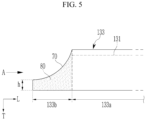
- FIG. 5 is a front view of the first sealing portion 133 of the rechargeable battery 100 shown in FIG. 1
- FIG. 6 is a partial plan view of the rechargeable battery 100 of FIG. 5 showing a state before the first sealing portion 133 of the rechargeable battery 100 shown in FIG. 5 is bent
- FIG. 7 is a view of the first sealing portion 133 of the rechargeable battery 100 of FIG. 5 viewed from a direction A of FIG. 5 .
- a length of the first sealing portion 133 along the length direction L may be greater than a length of the accommodating portion 131.
- One end portion (a left end portion as shown in FIG. 5 ) of the first sealing portion 133 may be disposed at a predetermined distance from the accommodating portion 131 along the length direction L.
- the first sealing portion 133 may include a first portion 133a that faces the accommodating portion 131 along the width direction W and a second portion 133b that does not face the accommodating portion 131 along the width direction W (e.g., as the second portion 133b extends past the accommodating portion 131 along the length direction L).
- the second portion 133b may be referred to as an extension portion.
- the cutout portion 70 may be disposed at the second portion 133b.
- a first sealing portion may have a rectangular shape and a corner of the second portion may be folded inward.
- the corner of the second portion 133b may be cut by mechanical cutting, laser cutting, or the like, and the cutout portion 70 may be disposed along the cut portion.
- the cutout portion 70 may be formed in an arc shape with a predetermined curvature.
- the cutout portion 70 may have a convex curve toward a lower end of the first sealing portion 133 as shown in FIG. 5 .
- the cutout portion 70 with the arc shape may prevent an end portion of the first sealing portion 133 from protruding as if a corner of the second portion 133b is folded inward, so that when a protection circuit such as a protection circuit module (PCM) or the like is coupled on the case 130, the case 130 and the protection circuit are easily coupled.
- PCM protection circuit module
- the cutout portion 70 may be disposed at a predetermined distance from a lower end of the bent first sealing portion 133 along the thickness direction T.
- one end portion of the cutout portion 70 that is close to the accommodating portion 131 may be in contact with an upper end of the first sealing portion 133, and the other end of the cutout portion 70 that is far from the accommodating portion 131 may have a height h from a lower end of the first sealing portion 133.
- the vent layer 80 may be disposed on a bonding surface of the second portion 133b so as to contact the cutout portion 70 and a corner of the accommodating portion 131.
- the bonding surface of the second portion 133b may be a bonding surface between the first sheet 40 and the second sheet 50, and the vent layer 80 may be disposed between the first sheet 40 and the second sheet 50 at the second portion 133b.
- the vent layer 80 may be provided on at least one of an inner surface of the first sheet 40 and an inner surface of the second sheet 50 corresponding to the second portion 133b considering a position of the cutout portion 70.
- the vent layer 80 may be bonded to at least one of the inner surfaces of the first and second sheets 40 and 50 by various methods such as adhesion by an adhesive, heat staking, welding, and the like.
- the vent layer 80 may be disposed on an entire bonding surface of the second portion 133b.
- the vent layer 80 may have a bonding degree lower than a bonding degree between the first sheet 40 and the second sheet 50 by heat staking, or may have a melting point lower than a melting point of a polymer layer included in the first and second sheets 40, 50.
- the vent layer 80 may simultaneously have the bonding degree lower than the bonding degree between the first sheet 40 and the second sheet 50 and the melting point lower than the melting point of the polymer layer included in the first and second sheets 40, 50.
- the bonding degree of the vent layer 80 may mean the bonding degree of the vent layer 80 with the first sheet 40 or the second sheet 50, or a bonding degree between two vent layers when the vent layer 80 is disposed on each of the inner surface of the first sheet 40 and the inner surface of the second sheet 50 to be bonded to each other.
- the bonding degree may have the same meaning as that of a bonding strength.
- the vent layer 80 may include any one of a polymer resin layer and a polymer resin-metal mixed layer satisfying the above-described condition.
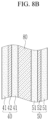
- FIG. 8A and FIG. 8B are partially enlarged views of the first sealing portion and the vent layer shown in FIG. 7 .
- the vent layer 80 may include a cast polypropylene (CPP) layer 81 and a coating layer 82 disposed on an outer surface of the cast polypropylene layer 81 (e.g., first and second coating layers 82 disposed on respective surfaces of the cast polypropylene (CPP) layer 81).
- the coating layer 82 may be a resin layer including polyethylene (PE) or the like, or a metal layer including aluminum (Al), copper (Cu), or the like.
- a melting point of the coating layer 82 may be about 100°C to 120°C, and as another example, may be about 105°C to 115°C.
- the temperature range may be lower than melting points of polymer layers 41, 51 of the first and second sheets 40, 50 that are about 140°C to 165°C.
- the vent layer 80 may be formed of a cast polypropylene (CPP) layer in which a resin such as polyethylene (PE) or the like is mixed or a metal such as aluminum (Al), copper (Cu), or the like is mixed.
- the first and second sheets 40, 50 may be bonded at a temperature condition of about 180°C to 230°C and a time condition of 1 second to 5 seconds, and in this case, a bonding strength between the first sheet 40 and the second sheet 50 may be about 1.5 kgf or more.
- a bonding strength of the vent layer 80 may be about 0.5 kgf to 1.4 kgf.
- the bonding strength range may be lower than the bonding strength between the first sheet 40 and the second sheet 50.
- a reference numeral 42 may represent a metal layer included in the first sheet 40
- a reference numeral 52 may represent a metal layer included in the second sheet 50.
- an internal temperature of a rechargeable battery may rise due to various causes such as overcharging, an internal short circuit, an external impact, exposure to a high-temperature environment, and the like.
- a gas may be generated due to vaporization of an electrolyte or the like. The gas generation may lead to an increase in an internal pressure of the rechargeable battery, and may cause ignition and/or explosion of the rechargeable battery.
- the vent layer 80 may be melted under a specific temperature condition to open the bonding surface, or may release the bonding under the specific pressure condition to open the bonding surface.
- a surface of the vent layer 80 may be melted at a specific temperature or higher, so that a gap between the first and second sheets 40, 50 and the vent layer 80 occurs.
- the vent layer 80 may be torn from the first and second sheets 40, 50, or the vent layer 80 may be destroyed so that a gap is generated between the first and second sheets 40, 50 and the vent layer 80 or inside the vent layer 80.
- An internal gas of the rechargeable battery 100 may reach the cutout portion 70 from a corner 131a of the accommodating portion 131 through a gap formed around the vent layer 80 or inside the vent layer 80, and may be quickly discharged to the outside through the opened cutout portion 70.
- a moving direction of the internal gas crossing the vent layer 80 is indicated by the arrows.
- the vent layer 80 may relieve the internal pressure by opening the bonding surface when the internal pressure of the rechargeable battery 100 increases.
- the rechargeable battery 100 of the present embodiment may reduce an overall size by bending the first sealing portion 133, and it may simultaneously improve safety by including the vent layer 80 at the second portion 133b of the first sealing portion 133.
- the cutout portion 70 may shorten a moving distance of the internal gas passing through the vent layer 80 from the corner 131a of the accommodating portion 131, so that the cutout portion 70 facilitates rapid gas discharging to enable rapid relief of the internal pressure.
- the internal gas may be discharged to the outside only by moving along a path corresponding to a width of the first sealing portion 133 from the corner 131a of the accommodating portion 131 or moving along a diagonal direction path from the corner 131a of the accommodating portion 131 to the corner of the second portion 133b.
- the configuration may hinder rapid discharging of the internal gas.
- a distance between the corner 131a of the accommodating portion 131 and an edge of the vent layer 80 may be shortened by the cutout portion 70, so that the cutout portion 70 enables rapid discharging of the gas.
- the rechargeable battery 100 of the present embodiment may quickly relieve the internal pressure in an abnormal situation where the internal temperature and the internal pressure rapidly rise, and may effectively prevent ignition and/or explosion of the rechargeable battery.
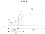
- FIG. 9 is a front view of a first sealing portion of a rechargeable battery according to a second embodiment
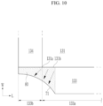
- FIG. 10 is a partial plan view of the rechargeable battery showing a state before the first sealing portion of the rechargeable battery shown in FIG. 9 is bent.
- the rechargeable battery of the second embodiment may have the same or similar configuration as that of the first embodiment described above except for the contents described below.
- a cutout portion 71 may be disposed across the first portion 133a and the second portion 133b of the first sealing portion 133, and the vent layer 80 may be disposed across an entire bonding surface of the second portion 133b and a portion of the bonding surface of the first portion 133a so as to contact the corner 131a of the accommodating portion 131 and the cutout portion 71.
- a length L1 of the cutout portion 71 along the length direction L of the rechargeable battery may be greater than a length L2 of the second portion 133b, and a portion of the vent layer 80 may face a side surface of the accommodating portion 131 along the width direction W of the rechargeable battery.
- the vent layer 80 may contact not only the corner 131a of the accommodating portion 131 but also a portion of an edge 131b of the accommodating portion 131 parallel to the length direction L.
- the vent layer 80 may be quickly melted or damaged to quickly open the bonding surface. Thus, the internal pressure may be relieved more quickly.
- a length of the vent layer 80 in contact with the accommodating portion 131 may be extended, and a movement path of the internal gas crossing the vent layer 80 from the accommodating portion 131 may be shortened.
- a direction of movement of the internal gas crossing the vent layer 80 is indicated by arrows.
- opening of the bonding surface of the vent layer 80 and gas discharging due to the opening may be performed more smoothly and/or efficiently.
- FIG. 11 is a front view of a first sealing portion of a rechargeable battery according to a third embodiment
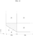
- FIG. 12 is a partial plan view of the rechargeable battery of FIG. 11 showing a state before the first sealing portion of the rechargeable battery shown in FIG. 11 is bent.
- the rechargeable battery of the third embodiment may have the same or similar configuration as that of the first embodiment described above except for the contents described below.
- a cutout portion 72 may have a straight-line shape, and the vent layer 80 may be provided on the bonding surface of the second portion 133b to contact the corner 131a of the accommodating portion 131 and the cutout portion 72.
- the corner of the second portion 133b may be cut into a straight line along a diagonal direction, and the cutout portion 72 with the straight-line shape may be disposed along the cut portion.
- the diagonal direction may be a direction inclined with respect to a lower end and left and right side surfaces of the second portion 133b based on FIG. 10 .
- FIG. 13 is a front view of a first sealing portion of a rechargeable battery according to a fourth embodiment
- FIG. 14 is a partial plan view of the rechargeable battery of FIG. 13 showing a state before the first sealing portion of the rechargeable battery shown in FIG. 13 is bent.
- the rechargeable battery of the fourth embodiment may have the same or similar configuration as that of the third embodiment described above except for the contents described below.
- a cutout portion 73 may be disposed across the first portion 133a and the second portion 133b of the first sealing portion 133, and the vent layer 80 may be disposed across an entire bonding surface of the second portion 133b and a portion of the bonding surface of the first portion 133a so as to contact the corner 131a of the accommodating portion 131 and the cutout portion 73.
- a length L3 of the cutout portion 73 along the length direction L of the rechargeable battery may be greater than a length L4 of the second portion 133b, and a portion of the vent layer 80 may face a side surface of the accommodating portion 131 along the width direction W of the rechargeable battery.
- the vent layer 80 may contact not only the corner 131a of the accommodating portion 131 but also a portion of an edge 131b of the accommodating portion 131 parallel to the length direction L.
- a length of the vent layer 80 in contact with the accommodating portion 131 may be extended, and a movement path of the internal gas crossing the vent layer 80 from the accommodating portion 131 may be shortened.
- a rechargeable battery comprising: an electrode assembly; a case that includes an accommodating portion surrounding the electrode assembly and a sealing portion connected to an edge of the accommodating portion and includes a first sheet and a second sheet disposed at an upper side and a lower side of the electrode assembly along a thickness direction; and a vent layer that is provided at the sealing portion, wherein the sealing portion is bent to face a side surface of the accommodating portion, a cutout portion is disposed at one end portion of the sealing portion, and the vent layer is disposed on a bonding surface between the first sheet and the second sheet while contacting a corner of the accommodating portion and the cutout portion.
- the sealing portion includes a pair of first sealing portions disposed at both sides of the accommodating portion, and each of the pair of first sealing portions includes a first portion facing the side surface of the accommodating portion and a second portion extending outward from the first portion.
- Clause 4 The rechargeable battery of clause 3, wherein the cutout portion has any one of an arc shape and a straight-line shape parallel to a diagonal direction.
- Clause 5 The rechargeable battery of clause 2, wherein the cutout portion is disposed continuously across a corner of the second portion and a portion of the first portion, and the vent layer is disposed continuously across an entire bonding surface of the second portion and a portion of a bonding surface of the first portion.
- each of the first sheet and the second sheet includes a polymer layer, and a melting point of the vent layer is less than a melting point of the polymer layer.
- Clause 10 The rechargeable battery of clause 1, wherein a bonding strength of the vent layer for at least one of the first sheet and the second sheet is less than a bonding strength between the first sheet and the second sheet.
- vent layer is formed of a cast polypropylene layer in which any one of a resin and a metal is mixed.
- Clause 12 The rechargeable battery of clause 11, wherein the bonding strength of the vent layer is 0.5 kgf to 1.4 kgf.
- a rechargeable battery comprising: an electrode assembly; a case that includes an accommodating portion surrounding the electrode assembly and a sealing portion connected to an edge of the accommodating portion and includes a first sheet and a second sheet disposed at an upper side and a lower side of the electrode assembly along a thickness direction; and a vent layer that is provided at the sealing portion, wherein the sealing portion includes a first portion facing a side surface of the accommodating portion by bending and a second portion extending outward from the first portion, a cutout portion is disposed at a corner of the second portion, and the vent layer is disposed on a bonding surface of the second portion to contact a corner of the accommodating portion and the cutout portion.
- Clause 14 The rechargeable battery of clause 13, wherein the cutout portion has any one of an arc shape and a straight-line shape parallel to a diagonal direction.
- Clause 15 The rechargeable battery of clause 13, wherein the cutout portion is disposed continuously across the corner of the second portion and a portion of the first portion, and the vent layer is disposed continuously across a bonding surface of the second portion and a portion of a bonding surface of the first portion to contact the entire cutout portion and a portion of the edge of the accommodating portion.
- vent layer is formed of any one of a cast polypropylene layer with a coating layer stacked on an outer surface thereof and a cast polypropylene layer in which any one of a resin and a metal is mixed.
Landscapes
- Chemical & Material Sciences (AREA)
- Chemical Kinetics & Catalysis (AREA)
- Electrochemistry (AREA)
- General Chemical & Material Sciences (AREA)
- Sealing Battery Cases Or Jackets (AREA)
Abstract
A rechargeable battery includes: an electrode assembly; a case comprising a first sheet disposed at an upper side of the electrode assembly in a thickness direction and a second sheet disposed at a lower side of the electrode assembly along the thickness direction, an accommodating portion at least partially surrounding the electrode assembly and formed by the first and second sheets, a sealing portion, formed by the first and second sheets connected to an edge of the accommodating portion and bent to face a side surface of the accommodating portion, the sealing portion comprising a vent layer provided in the sealing portion, and a cutout portion disposed at one end portion of the sealing portion, wherein the vent layer is disposed on a bonding surface between the first sheet and the second sheet and contacts a corner of the accommodating portion and the cutout portion.
Description
- The present disclosure relates to a rechargeable battery, and more particularly, to a case of a pouch-type battery, and to a method of manufacturing a rechargeable battery.
- A chargeable battery is used for various purposes such as a power source for a small electronic device such as a mobile phone or a laptop computer, a power source for driving a motor in a transportation vehicle such as an electric vehicle or a hybrid vehicle, and the like. In the former case, a pouch-type battery is mainly used to facilitate the miniaturization and slimming of the small electronic device.
- An internal temperature and an internal pressure of the rechargeable battery may rapidly rise due to various causes such as fast charging, an internal short circuit, an external impact, exposure to a high-temperature environment, and the like.
- The present disclosure provides a rechargeable battery capable of easily discharging an internal gas under a predetermined temperature and pressure condition by having a vent function optimized for a sealing structure of a pouch-type battery. The present disclosure also provides a method of manufacturing a rechargeable battery.
- A rechargeable battery according to a first aspect includes:
- an electrode assembly;
- a case comprising:
- a first sheet disposed at an upper side of the electrode assembly along a thickness direction;
- a second sheet disposed at a lower side of the electrode assembly along the thickness direction;
- an accommodating portion at least partially surrounding the electrode assembly;
- a sealing portion connected to an edge of the accommodating portion,
- a vent layer that is provided at the sealing portion; and
- a cutout portion,
- wherein the sealing portion is bent to face a side surface of the accommodating portion,
- wherein the cutout portion is disposed at one end portion of the sealing portion, and
- wherein the vent layer is disposed on a bonding surface between the first sheet and the second sheet and contacts a corner of the accommodating portion and the cutout portion.
- The accommodating portion may be formed by the first and second sheets.
- The sealing portion may be formed by the first and second sheets.
- The sealing portion may include a pair of first sealing portions, each respective one of the pair of first sealing portions being disposed on a respective side of the accommodating portion, and each of the pair of first sealing portions may include a first portion facing the side surface of the accommodating portion and a second portion extending outward from the first portion.
- The cutout portion may be disposed at a corner of the second portion of a respective one of the pair of first sealing portions, and the vent layer may be provided on an entire bonding surface of the second portion of a respective one of the pair of first sealing portions.
- The cutout portion may have any one of an arc shape or a straight-line shape parallel to a diagonal direction.
- The cutout portion may be disposed continuously across a corner of the second portion and a portion of the first portion of a respective one of the pair of first sealing portions, and the vent layer may be disposed continuously across an entire bonding surface of the second portion and a portion of a bonding surface of the first portion of a respective one of the pair of first sealing portions.
- The cutout portion may have any one of an arc shape or a straight-line shape parallel to a diagonal direction.
- Each of the first sheet and the second sheet may include a polymer layer, and a melting point of the vent layer may be less than a melting point of the polymer layer.
- The vent layer may be formed of a cast polypropylene layer with a coating layer stacked on an outer surface thereof.
- A melting point of the coating layer may be 105°C to 115°C.
- A bonding strength of the vent layer to at least one of the first sheet and/or the second sheet may be less than a bonding strength between the first sheet and the second sheet.
- The vent layer may be formed of a cast polypropylene layer in which any one of a resin and a metal is mixed.
- The bonding strength of the vent layer may be 0.5 kgf to 1.4 kgf.
- A rechargeable battery according to another aspect includes:
- an electrode assembly; and
- a case comprising:
- a first sheet disposed at an upper side of the electrode assembly along a thickness direction;
- a second sheet disposed at a lower side of the electrode assembly along the thickness direction;
- an accommodating portion at least partially surrounding the electrode assembly;
- a sealing portion connected to an edge of the accommodating portion;
- a vent layer provided at the sealing portion; and
- a cutout portion,
- wherein the sealing portion includes a first portion facing a side surface of the accommodating portion by bending and a second portion extending outward from the first portion,
- wherein the cutout portion is disposed at a corner of the second portion, and
- wherein the vent layer is disposed on a bonding surface of the second portion and contacts a corner of the accommodating portion and the cutout portion.
- The accommodating portion may be formed by the first and second sheets.
- The sealing portion may be formed by the first and second sheets.
- The cutout portion may have any one of an arc shape or a straight-line shape parallel to a diagonal direction. The cutout portion may be disposed continuously across the corner of the second portion and a portion of the first portion, and the vent layer may be disposed continuously across a bonding surface of the second portion and a portion of a bonding surface of the first portion to contact the entire cutout portion and a portion of the edge of the accommodating portion.
- The vent layer may be formed of any one of a cast polypropylene layer with a coating layer stacked on an outer surface thereof or a cast polypropylene layer in which any one of a resin and/or a metal is mixed.
- According to another aspect, there is provided a method of manufacturing a rechargeable battery according to the appended claims.
- According to the embodiments, an overall size of the rechargeable battery may be reduced by bending of a sealing portion, and safety of the rechargeable battery may be improved using a cutout portion and a vent layer. Because the cutout portion shortens a moving distance of an internal gas passing through the vent layer from a corner of an accommodating portion, the cutout portion may facilitate gas discharging to enable rapid relief of an internal pressure.
- At least some of the above and other features of the invention are set out in the claims.
-
-
FIG. 1 is a perspective view of a rechargeable battery according to a first embodiment. -
FIG. 2 is a cross-sectional view of the rechargeable battery cut along a line II-II ofFIG. 1 . -
FIG. 3 is a partially enlarged view of an electrode assembly of the rechargeable battery shown inFIG. 2 . -
FIG. 4 is a view showing a state before a first sealing portion of the rechargeable battery shown inFIG. 2 is bent. -
FIG. 5 is a front view of a first sealing portion of the rechargeable battery shown inFIG. 1 . -
FIG. 6 is a partial plan view of the rechargeable battery showing a state before the first sealing portion of the rechargeable battery shown inFIG. 5 is bent. -
FIG. 7 is a view of the first sealing portion of the rechargeable battery ofFIG. 5 viewed from a direction A ofFIG. 5 . -
FIG. 8A andFIG. 8B are partially enlarged views of the first sealing portion and a vent layer of the rechargeable battery shown inFIG. 7 . -
FIG. 9 is a front view of a first sealing portion of a rechargeable battery according to a second embodiment. -
FIG. 10 is a partial plan view of the rechargeable battery ofFIG. 9 showing a state before the first sealing portion of the rechargeable battery shown inFIG. 9 is bent. -
FIG. 11 is a front view of a first sealing portion of a rechargeable battery according to a third embodiment. -
FIG. 12 is a partial plan view of the rechargeable battery ofFIG. 11 showing a state before the first sealing portion of the rechargeable battery shown inFIG. 11 is bent. -
FIG. 13 is a front view of a first sealing portion of a rechargeable battery according to a fourth embodiment. -
FIG. 14 is a partial plan view of the rechargeable battery ofFIG. 13 showing a state before the first sealing portion of the rechargeable battery shown inFIG. 13 is bent. - Embodiments of the present disclosure will be described more fully hereinafter with reference to the accompanying drawings so that those skilled in the art can easily implement the embodiments. The present disclosure may be modified in various different ways, all without departing from the scope of the present disclosure.
- An internal temperature and an internal pressure of a rechargeable battery may rapidly rise due to various causes such as fast charging, an internal short circuit, an external impact, exposure to a high-temperature environment, and the like. The rechargeable battery described herein has a vent function for discharging an internal gas under a preset temperature and pressure condition to prevent ignition and/or explosion due to the increase in the temperature and the pressure.
-
FIG. 1 is a perspective view of arechargeable battery 100 according to a first embodiment, andFIG. 2 is a cross-sectional view of therechargeable battery 100 cut along a line II-II ofFIG. 1 .FIG. 3 is a partially enlarged view of anelectrode assembly 120 of therechargeable battery 100 shown inFIG. 2 , andFIG. 4 is a view showing a state before a first sealing portion of therechargeable battery 100 shown inFIG. 2 is bent. - Referring to
FIGS. 1 to 4 , therechargeable battery 100 according to the present embodiment may include theelectrode assembly 120 and acase 130 accommodating and sealing theelectrode assembly 120 together with an electrolyte. Thecase 130 may be referred to as a pouch, and may include acutout portion 70 and avent layer 80 that will be described later. - The
electrode assembly 120 may include afirst electrode 10 and asecond electrode 20 disposed with aseparator 30 interposed therebetween. Thefirst electrode 10 may include afirst substrate 11, firstcomposite layer 12 disposed on both surfaces of the first substrate 11 (e.g., first and second firstcomposite layers 12 disposed on both surfaces of the first substrate 11), and a first electrode tab 13 extending from thefirst substrate 11 to one side (e.g., along the length axis "L" shown inFIG. 1 ). Thesecond electrode 20 may include asecond substrate 21, secondcomposite layer 22 disposed on both surfaces of the second substrate 21 (e.g., first and second second composite layers 22 disposed on respective surfaces of the second substrate 21), and asecond electrode tab 23 extending from thesecond substrate 21 to one side (e.g., along the length axis "L" shown inFIG. 1 ). - In a lithium ion battery, the
first substrate 11 may be formed of an aluminum foil, and the firstcomposite layer 12 may include transition metal oxide such as LiCoO2, LiNiO2, LiMn2O4, Li(NiCoAl)O2, LiFePO4, Li(NiCoMn)O2, or the like, a conductive material, a binder, or the like. Thesecond substrate 21 may be formed of a copper foil or a nickel foil, and the secondcomposite layer 22 may include graphite, a conductive material, a binder, or the like. Thefirst electrode 10 may be referred to as a positive electrode, andsecond electrode 20 may be referred to as a negative electrode. - The
separator 30 may include a polymer material such as polyethylene (PE), polypropylene (PP), or the like, and may insulate thefirst electrode 10 and thesecond electrode 20 while allowing movement of a lithium ion. - The
electrode assembly 120 may be configured to be flat pressed after thefirst electrode 10, theseparator 30, and thesecond electrode 20 are wound around two winding axes, and may be a wound type electrode assembly. Theelectrode assembly 120 may have a configuration in which a plurality offirst electrodes 10 and a plurality ofsecond electrodes 20 are alternately stacked one by one with theseparator 30 interposed therebetween, and may be a stacked type electrode assembly. In the latter case, a plurality of separators individually separated may be used, or one separator folded in a zigzag pattern may be used. InFIG. 2 , acase 130 where theelectrode assembly 120 has the wound type is shown as an example. - The
electrode assembly 120 may have a rectangular shape with a pair of long sides (e.g., running along a length axis "L") and a pair of short sides (e.g., running along a width axis "W") on a plane. Hereinafter, the phrase "on a plane" may mean when an object portion is viewed from above. - In the present embodiment, a direction parallel to the long side of the
electrode assembly 120 may be referred to as a length direction L of therechargeable battery 100, and a direction parallel to the short side of theelectrode assembly 120 may be referred to as a width direction W of therechargeable battery 100. A direction orthogonal to the length direction L and the width direction W may be referred to as a thickness direction T of therechargeable battery 100. The first electrode tab 13 and thesecond electrode tab 23 may extend along the length direction L from one short side of theelectrode assembly 120, and the first andsecond electrode tabs 13, 23 may be disposed at a distance from each other along the width direction W. - The
case 130 may include afirst sheet 40 and asecond sheet 50 disposed at both sides (upper and lower sides) of theelectrode assembly 120 along the thickness direction T. For example, thefirst sheet 40 may be disposed at an upper side of theelectrode assembly 120 and thesecond sheet 50 may be disposed at a lower side of theelectrode assembly 120. Each of thefirst sheet 40 and thesecond sheet 50 may be formed of a composite sheet, and may have a larger area than that of theelectrode assembly 120. One of thefirst sheet 40 and the second sheet 50 (for example, the first sheet 40) may have aconcave portion 45 capable of accommodating theelectrode assembly 120 e.g. provided by a drawing processing. - The composite sheet may have a three-layer structure including a first polymer layer, a metal layer, and a second polymer layer. The metal layer may include aluminum, and may provide mechanical strength to the
case 130. The first and/or second polymer layers may include any one of modified polypropylene (PP), polyethylene terephthalate (PET), nylon, and/or PET-nylon, and may provide insulation and protection functions to thecase 130. - After the
electrode assembly 120 is accommodated in theconcave portion 45 of thefirst sheet 40, edges of thefirst sheet 40 and thesecond sheet 50 may be integrally bonded by heat staking (or thermal fusion). Thecase 130 may include anaccommodating portion 131 accommodating theelectrode assembly 120, and a sealingportion 132 connected to an edge of theaccommodating portion 131. A central portion of the first andsecond sheets electrode assembly 120 may form theaccommodating portion 131, and edge portions of the first andsecond sheets portion 132. For example, the sealingportion 132 may be formed of a bonded body of thefirst sheet 40 and thesecond sheet 50. - The sealing
portion 132 may include a pair offirst sealing portions 133 parallel to the length direction L, and a pair ofsecond sealing portions 134 parallel to the width direction W. The first andsecond electrode tabs 13, 23 may pass through any one of thesecond sealing portions 134 to protrude to the outside of thecase 130, and may function as electrode terminals supplying an electric current to an external device. The first andsecond electrode tabs 13, 23 may overlap thesecond sealing portion 134 at a portion surrounded by aprotective tape 60. - The
first sealing portion 133 may be bent to face a side surface of theaccommodating portion 131 so as to reduce an overall size of therechargeable battery 100. As shown inFIG. 4 , an initialfirst sealing portion 133 may be disposed parallel to an upper surface and a lower surface of theelectrode assembly 120. This may enlarge the overall size of therechargeable battery 100. Because the overall size of therechargeable battery 100 has to be reduced in order to reduce a size of an electronic device, thefirst sealing portion 133 may be bent to be disposed parallel to the side surface of the accommodating portion 131 (e.g., parallel to the thickness direction "T"). - If the
first sheet 40 with theconcave portion 45 is provided, thefirst sealing portion 133, before thefirst sealing portion 133 is bent, may be disposed at substantially the same height as that of thesecond sheet 50. Thefirst sealing portion 133 may be vertically bent upward (e.g. from the position shown inFIG. 4 ) to be disposed parallel to a side surface of the electrode assembly 120 (e.g. as shown inFIG. 2 ). - Like the
first sealing portion 133, thesecond sealing portion 134 disposed opposite to the first andsecond electrode tabs 13, 23 may be vertically bent to face the side surface of theaccommodating portion 131. -
FIG. 5 is a front view of thefirst sealing portion 133 of therechargeable battery 100 shown inFIG. 1 , andFIG. 6 is a partial plan view of therechargeable battery 100 ofFIG. 5 showing a state before thefirst sealing portion 133 of therechargeable battery 100 shown inFIG. 5 is bent.FIG. 7 is a view of thefirst sealing portion 133 of therechargeable battery 100 ofFIG. 5 viewed from a direction A ofFIG. 5 . - Referring to
FIGS. 5 to 7 , a length of thefirst sealing portion 133 along the length direction L may be greater than a length of theaccommodating portion 131. One end portion (a left end portion as shown inFIG. 5 ) of thefirst sealing portion 133 may be disposed at a predetermined distance from theaccommodating portion 131 along the length direction L. Thefirst sealing portion 133 may include afirst portion 133a that faces theaccommodating portion 131 along the width direction W and asecond portion 133b that does not face theaccommodating portion 131 along the width direction W (e.g., as thesecond portion 133b extends past theaccommodating portion 131 along the length direction L). Thesecond portion 133b may be referred to as an extension portion. - The
cutout portion 70 may be disposed at thesecond portion 133b. In a typical rechargeable battery, generally, a first sealing portion may have a rectangular shape and a corner of the second portion may be folded inward. However, in therechargeable battery 100 of the present embodiment, the corner of thesecond portion 133b may be cut by mechanical cutting, laser cutting, or the like, and thecutout portion 70 may be disposed along the cut portion. - The
cutout portion 70 may be formed in an arc shape with a predetermined curvature. Thecutout portion 70 may have a convex curve toward a lower end of thefirst sealing portion 133 as shown inFIG. 5 . Thecutout portion 70 with the arc shape may prevent an end portion of thefirst sealing portion 133 from protruding as if a corner of thesecond portion 133b is folded inward, so that when a protection circuit such as a protection circuit module (PCM) or the like is coupled on thecase 130, thecase 130 and the protection circuit are easily coupled. - The
cutout portion 70 may be disposed at a predetermined distance from a lower end of the bentfirst sealing portion 133 along the thickness direction T. For example, one end portion of thecutout portion 70 that is close to theaccommodating portion 131 may be in contact with an upper end of thefirst sealing portion 133, and the other end of thecutout portion 70 that is far from theaccommodating portion 131 may have a height h from a lower end of thefirst sealing portion 133. - The
vent layer 80 may be disposed on a bonding surface of thesecond portion 133b so as to contact thecutout portion 70 and a corner of theaccommodating portion 131. The bonding surface of thesecond portion 133b may be a bonding surface between thefirst sheet 40 and thesecond sheet 50, and thevent layer 80 may be disposed between thefirst sheet 40 and thesecond sheet 50 at thesecond portion 133b. - When the
first sheet 40 and thesecond sheet 50 are manufactured, thevent layer 80 may be provided on at least one of an inner surface of thefirst sheet 40 and an inner surface of thesecond sheet 50 corresponding to thesecond portion 133b considering a position of thecutout portion 70. Thevent layer 80 may be bonded to at least one of the inner surfaces of the first andsecond sheets vent layer 80 may be disposed on an entire bonding surface of thesecond portion 133b. - The
vent layer 80 may have a bonding degree lower than a bonding degree between thefirst sheet 40 and thesecond sheet 50 by heat staking, or may have a melting point lower than a melting point of a polymer layer included in the first andsecond sheets vent layer 80 may simultaneously have the bonding degree lower than the bonding degree between thefirst sheet 40 and thesecond sheet 50 and the melting point lower than the melting point of the polymer layer included in the first andsecond sheets - For example, the bonding degree of the
vent layer 80 may mean the bonding degree of thevent layer 80 with thefirst sheet 40 or thesecond sheet 50, or a bonding degree between two vent layers when thevent layer 80 is disposed on each of the inner surface of thefirst sheet 40 and the inner surface of thesecond sheet 50 to be bonded to each other. The bonding degree may have the same meaning as that of a bonding strength. Thevent layer 80 may include any one of a polymer resin layer and a polymer resin-metal mixed layer satisfying the above-described condition. -
FIG. 8A andFIG. 8B are partially enlarged views of the first sealing portion and the vent layer shown inFIG. 7 . - Referring to
FIG. 8A , thevent layer 80 may include a cast polypropylene (CPP)layer 81 and acoating layer 82 disposed on an outer surface of the cast polypropylene layer 81 (e.g., first and second coating layers 82 disposed on respective surfaces of the cast polypropylene (CPP) layer 81). Thecoating layer 82 may be a resin layer including polyethylene (PE) or the like, or a metal layer including aluminum (Al), copper (Cu), or the like. A melting point of thecoating layer 82 may be about 100°C to 120°C, and as another example, may be about 105°C to 115°C. The temperature range may be lower than melting points of polymer layers 41, 51 of the first andsecond sheets - Referring to
FIG. 8B , thevent layer 80 may be formed of a cast polypropylene (CPP) layer in which a resin such as polyethylene (PE) or the like is mixed or a metal such as aluminum (Al), copper (Cu), or the like is mixed. The first andsecond sheets first sheet 40 and thesecond sheet 50 may be about 1.5 kgf or more. A bonding strength of thevent layer 80 may be about 0.5 kgf to 1.4 kgf. The bonding strength range may be lower than the bonding strength between thefirst sheet 40 and thesecond sheet 50. - For reference, in
FIG. 8A andFIG. 8B , areference numeral 42 may represent a metal layer included in thefirst sheet 40, and areference numeral 52 may represent a metal layer included in thesecond sheet 50. - In general, an internal temperature of a rechargeable battery may rise due to various causes such as overcharging, an internal short circuit, an external impact, exposure to a high-temperature environment, and the like. In this case, a gas may be generated due to vaporization of an electrolyte or the like. The gas generation may lead to an increase in an internal pressure of the rechargeable battery, and may cause ignition and/or explosion of the rechargeable battery.
- Referring back to
FIGS. 5 to 7 , thevent layer 80 may be melted under a specific temperature condition to open the bonding surface, or may release the bonding under the specific pressure condition to open the bonding surface. - For example, a surface of the vent layer 80 (for example, the
coating layer 82 ofFIG. 8A ) may be melted at a specific temperature or higher, so that a gap between the first andsecond sheets vent layer 80 occurs. In some embodiments, if a pressure applied to thevent layer 80 becomes greater than the bonding degree of thevent layer 80, thevent layer 80 may be torn from the first andsecond sheets vent layer 80 may be destroyed so that a gap is generated between the first andsecond sheets vent layer 80 or inside thevent layer 80. - An internal gas of the
rechargeable battery 100 may reach thecutout portion 70 from acorner 131a of theaccommodating portion 131 through a gap formed around thevent layer 80 or inside thevent layer 80, and may be quickly discharged to the outside through the openedcutout portion 70. InFIG. 6 , a moving direction of the internal gas crossing thevent layer 80 is indicated by the arrows. Thevent layer 80 may relieve the internal pressure by opening the bonding surface when the internal pressure of therechargeable battery 100 increases. - The
rechargeable battery 100 of the present embodiment may reduce an overall size by bending thefirst sealing portion 133, and it may simultaneously improve safety by including thevent layer 80 at thesecond portion 133b of thefirst sealing portion 133. For example, thecutout portion 70 may shorten a moving distance of the internal gas passing through thevent layer 80 from thecorner 131a of theaccommodating portion 131, so that thecutout portion 70 facilitates rapid gas discharging to enable rapid relief of the internal pressure. - If there is no
cutout portion 70 in thesecond portion 133b and thevent layer 80 is disposed on an entire bonding surface of thesecond portion 133b, the internal gas may be discharged to the outside only by moving along a path corresponding to a width of thefirst sealing portion 133 from thecorner 131a of theaccommodating portion 131 or moving along a diagonal direction path from thecorner 131a of theaccommodating portion 131 to the corner of thesecond portion 133b. The configuration may hinder rapid discharging of the internal gas. - In the present embodiment, a distance between the
corner 131a of theaccommodating portion 131 and an edge of thevent layer 80 may be shortened by thecutout portion 70, so that thecutout portion 70 enables rapid discharging of the gas. For example, therechargeable battery 100 of the present embodiment may quickly relieve the internal pressure in an abnormal situation where the internal temperature and the internal pressure rapidly rise, and may effectively prevent ignition and/or explosion of the rechargeable battery. -
FIG. 9 is a front view of a first sealing portion of a rechargeable battery according to a second embodiment, andFIG. 10 is a partial plan view of the rechargeable battery showing a state before the first sealing portion of the rechargeable battery shown inFIG. 9 is bent. The rechargeable battery of the second embodiment may have the same or similar configuration as that of the first embodiment described above except for the contents described below. - Referring to
FIG. 9 andFIG. 10 , in the second embodiment, acutout portion 71 may be disposed across thefirst portion 133a and thesecond portion 133b of thefirst sealing portion 133, and thevent layer 80 may be disposed across an entire bonding surface of thesecond portion 133b and a portion of the bonding surface of thefirst portion 133a so as to contact thecorner 131a of theaccommodating portion 131 and thecutout portion 71. A length L1 of thecutout portion 71 along the length direction L of the rechargeable battery may be greater than a length L2 of thesecond portion 133b, and a portion of thevent layer 80 may face a side surface of theaccommodating portion 131 along the width direction W of the rechargeable battery. - In the second embodiment, the
vent layer 80 may contact not only thecorner 131a of theaccommodating portion 131 but also a portion of anedge 131b of theaccommodating portion 131 parallel to the length direction L. In the structure, when the temperature and the pressure of the rechargeable battery are increased, thevent layer 80 may be quickly melted or damaged to quickly open the bonding surface. Thus, the internal pressure may be relieved more quickly. - In the second embodiment, compared with the first embodiment, a length of the
vent layer 80 in contact with theaccommodating portion 131 may be extended, and a movement path of the internal gas crossing thevent layer 80 from theaccommodating portion 131 may be shortened. InFIG. 10 , a direction of movement of the internal gas crossing thevent layer 80 is indicated by arrows. In the second embodiment, when the temperature and the pressure of the rechargeable battery are increased, opening of the bonding surface of thevent layer 80 and gas discharging due to the opening may be performed more smoothly and/or efficiently. -
FIG. 11 is a front view of a first sealing portion of a rechargeable battery according to a third embodiment, andFIG. 12 is a partial plan view of the rechargeable battery ofFIG. 11 showing a state before the first sealing portion of the rechargeable battery shown inFIG. 11 is bent. The rechargeable battery of the third embodiment may have the same or similar configuration as that of the first embodiment described above except for the contents described below. - Referring to
FIG. 11 andFIG. 12 , in the third embodiment, acutout portion 72 may have a straight-line shape, and thevent layer 80 may be provided on the bonding surface of thesecond portion 133b to contact thecorner 131a of theaccommodating portion 131 and thecutout portion 72. The corner of thesecond portion 133b may be cut into a straight line along a diagonal direction, and thecutout portion 72 with the straight-line shape may be disposed along the cut portion. For example, the diagonal direction may be a direction inclined with respect to a lower end and left and right side surfaces of thesecond portion 133b based onFIG. 10 . -
FIG. 13 is a front view of a first sealing portion of a rechargeable battery according to a fourth embodiment, andFIG. 14 is a partial plan view of the rechargeable battery ofFIG. 13 showing a state before the first sealing portion of the rechargeable battery shown inFIG. 13 is bent. The rechargeable battery of the fourth embodiment may have the same or similar configuration as that of the third embodiment described above except for the contents described below. - Referring to
FIG. 13 andFIG. 14 , in the fourth embodiment, acutout portion 73 may be disposed across thefirst portion 133a and thesecond portion 133b of thefirst sealing portion 133, and thevent layer 80 may be disposed across an entire bonding surface of thesecond portion 133b and a portion of the bonding surface of thefirst portion 133a so as to contact thecorner 131a of theaccommodating portion 131 and thecutout portion 73. A length L3 of thecutout portion 73 along the length direction L of the rechargeable battery may be greater than a length L4 of thesecond portion 133b, and a portion of thevent layer 80 may face a side surface of theaccommodating portion 131 along the width direction W of the rechargeable battery. - In the fourth embodiment, the
vent layer 80 may contact not only thecorner 131a of theaccommodating portion 131 but also a portion of anedge 131b of theaccommodating portion 131 parallel to the length direction L. In the fourth embodiment, compared with the third embodiment, a length of thevent layer 80 in contact with theaccommodating portion 131 may be extended, and a movement path of the internal gas crossing thevent layer 80 from theaccommodating portion 131 may be shortened. Thus, when the temperature and the internal pressure of the rechargeable battery are increased, opening of the bonding surface of thevent layer 80 and gas discharging due to the opening may be performed more smoothly and/or efficiently. - Embodiments are set out in the following clauses.
-
Clause 1. A rechargeable battery comprising: an electrode assembly; a case that includes an accommodating portion surrounding the electrode assembly and a sealing portion connected to an edge of the accommodating portion and includes a first sheet and a second sheet disposed at an upper side and a lower side of the electrode assembly along a thickness direction; and a vent layer that is provided at the sealing portion, wherein the sealing portion is bent to face a side surface of the accommodating portion, a cutout portion is disposed at one end portion of the sealing portion, and the vent layer is disposed on a bonding surface between the first sheet and the second sheet while contacting a corner of the accommodating portion and the cutout portion. - Clause 2. The rechargeable battery of
clause 1, wherein the sealing portion includes a pair of first sealing portions disposed at both sides of the accommodating portion, and each of the pair of first sealing portions includes a first portion facing the side surface of the accommodating portion and a second portion extending outward from the first portion. - Clause 3. The rechargeable battery of clause 2, wherein the cutout portion is disposed at a corner of the second portion, and the vent layer is provided on an entire bonding surface of the second portion.
- Clause 4. The rechargeable battery of clause 3, wherein the cutout portion has any one of an arc shape and a straight-line shape parallel to a diagonal direction.
- Clause 5. The rechargeable battery of clause 2, wherein the cutout portion is disposed continuously across a corner of the second portion and a portion of the first portion, and the vent layer is disposed continuously across an entire bonding surface of the second portion and a portion of a bonding surface of the first portion.
- Clause 6. The rechargeable battery of clause 5, wherein the cutout portion has any one of an arc shape and a straight-line shape parallel to a diagonal direction.
- Clause 7. The rechargeable battery of
clause 1, wherein each of the first sheet and the second sheet includes a polymer layer, and a melting point of the vent layer is less than a melting point of the polymer layer. - Clause 8. The rechargeable battery of clause 7, wherein the vent layer is formed of a cast polypropylene layer with a coating layer stacked on an outer surface thereof.
- Clause 9. The rechargeable battery of clause 8, wherein a melting point of the coating layer is 105°C to 115°C.
-
Clause 10. The rechargeable battery ofclause 1, wherein a bonding strength of the vent layer for at least one of the first sheet and the second sheet is less than a bonding strength between the first sheet and the second sheet. -
Clause 11. The rechargeable battery ofclause 10, wherein the vent layer is formed of a cast polypropylene layer in which any one of a resin and a metal is mixed. -
Clause 12. The rechargeable battery ofclause 11, wherein the bonding strength of the vent layer is 0.5 kgf to 1.4 kgf. - Clause 13. A rechargeable battery comprising: an electrode assembly; a case that includes an accommodating portion surrounding the electrode assembly and a sealing portion connected to an edge of the accommodating portion and includes a first sheet and a second sheet disposed at an upper side and a lower side of the electrode assembly along a thickness direction; and a vent layer that is provided at the sealing portion, wherein the sealing portion includes a first portion facing a side surface of the accommodating portion by bending and a second portion extending outward from the first portion, a cutout portion is disposed at a corner of the second portion, and the vent layer is disposed on a bonding surface of the second portion to contact a corner of the accommodating portion and the cutout portion.
- Clause 14. The rechargeable battery of clause 13, wherein the cutout portion has any one of an arc shape and a straight-line shape parallel to a diagonal direction.
- Clause 15. The rechargeable battery of clause 13, wherein the cutout portion is disposed continuously across the corner of the second portion and a portion of the first portion, and the vent layer is disposed continuously across a bonding surface of the second portion and a portion of a bonding surface of the first portion to contact the entire cutout portion and a portion of the edge of the accommodating portion.
- Clause 16. The rechargeable battery of clause 13, wherein the vent layer is formed of any one of a cast polypropylene layer with a coating layer stacked on an outer surface thereof and a cast polypropylene layer in which any one of a resin and a metal is mixed.
- While this disclosure has been described in connection with what is presently considered to be practical embodiments, it is to be understood that the disclosure is not limited to the disclosed embodiments. On the contrary, it is intended to cover various modifications and equivalent arrangements included within the scope of the appended claims.
Claims (15)
- A rechargeable battery comprising:an electrode assembly; anda case comprising:a first sheet disposed at an upper side of the electrode assembly along a thickness direction;a second sheet disposed at a lower side of the electrode assembly along the thickness direction;an accommodating portion at least partially surrounding the electrode assembly;a sealing portion connected to an edge of the accommodating portion;a vent layer provided at the sealing portion; anda cutout portion,wherein the sealing portion is bent to face a side surface of the accommodating portion,wherein the cutout portion is disposed at one end portion of the sealing portion, andwherein the vent layer is disposed on a bonding surface between the first sheet and the second sheet and contacts a corner of the accommodating portion and the cutout portion.
- The rechargeable battery of claim 1, wherein:the sealing portion includes a pair of first sealing portions, each respective one of the pair of first sealing portions being disposed on a respective side of the accommodating portion; andeach of the pair of first sealing portions includes a first portion facing the side surface of the accommodating portion and a second portion extending outward from the first portion.
- The rechargeable battery of claim 2, wherein:the cutout portion is disposed at a corner of the second portion of a respective one of the pair of first sealing portions; andthe vent layer is provided on an entire bonding surface of the second portion of a respective one of the pair of first sealing portions.
- The rechargeable battery of claim 3, wherein:
the cutout portion has any one of an arc shape or a straight-line shape parallel to a diagonal direction. - The rechargeable battery of claim 2, wherein:the cutout portion is disposed continuously across a corner of the second portion and a portion of the first portion of a respective one of the pair of first sealing portions; andthe vent layer is disposed continuously across an entire bonding surface of the second portion and a portion of a bonding surface of the first portion of a respective one of the pair of first sealing portions.
- The rechargeable battery of claim 5, wherein:
the cutout portion has any one of an arc shape or a straight-line shape parallel to a diagonal direction. - The rechargeable battery of any preceding claim, wherein:each of the first sheet and the second sheet includes a polymer layer; anda melting point of the vent layer is less than a melting point of the polymer layer.
- The rechargeable battery of claim 7, wherein:the vent layer is formed of a cast polypropylene layer with a coating layer stacked on an outer surface thereof,and wherein optionally:
a melting point of the coating layer is 105°C to 115°C. - The rechargeable battery of any preceding claim, wherein:a bonding strength of the vent layer to at least one of the first sheet and/or the second sheet is less than a bonding strength between the first sheet and the second sheet,and wherein optionally the bonding strength of the vent layer is 0.5 kgf to 1.4 kgf.
- The rechargeable battery of any preceding claim, wherein:
the vent layer is formed of a cast polypropylene layer in which any one of a resin and/or a metal is mixed. - A rechargeable battery comprising:an electrode assembly; anda case comprising:a first sheet disposed at an upper side of the electrode assembly along a thickness direction;a second sheet disposed at a lower side of the electrode assembly along the thickness direction;an accommodating portion at least partially surrounding the electrode assembly;a sealing portion connected to an edge of the accommodating portion;a vent layer provided at the sealing portion; anda cutout portion,wherein the sealing portion includes a first portion facing a side surface of the accommodating portion by bending and a second portion extending outward from the first portion,wherein the cutout portion is disposed at a corner of the second portion, andwherein the vent layer is disposed on a bonding surface of the second portion and contacts a corner of the accommodating portion and the cutout portion.
- The rechargeable battery of claim 11, wherein:
the cutout portion has any one of an arc shape or a straight-line shape parallel to a diagonal direction. - The rechargeable battery of claim 11 or 12, wherein:the cutout portion is disposed continuously across the corner of the second portion and a portion of the first portion; andthe vent layer is disposed continuously across a bonding surface of the second portion and a portion of a bonding surface of the first portion to contact the entire cutout portion and a portion of the edge of the accommodating portion.
- The rechargeable battery of claim 11, 12 or 13, wherein:
the vent layer is formed of any one of a cast polypropylene layer with a coating layer stacked on an outer surface thereof or a cast polypropylene layer in which any one of a resin and/or a metal is mixed. - A method of manufacturing a rechargeable battery comprising:forming a case for an electrode assembly,wherein the case comprises the case according to any one of claims 1 to 10 or the case according to any one of claims 11 to 14; anddisposing the electrode assembly inside the case.
Applications Claiming Priority (1)
| Application Number | Priority Date | Filing Date | Title |
|---|---|---|---|
| KR1020230152966A KR20250066884A (en) | 2023-11-07 | 2023-11-07 | Secondary battery |
Publications (1)
| Publication Number | Publication Date |
|---|---|
| EP4553964A1 true EP4553964A1 (en) | 2025-05-14 |
Family
ID=93432144
Family Applications (1)
| Application Number | Title | Priority Date | Filing Date |
|---|---|---|---|
| EP24211273.8A Pending EP4553964A1 (en) | 2023-11-07 | 2024-11-06 | Rechargeable battery |
Country Status (4)
| Country | Link |
|---|---|
| US (1) | US20250149724A1 (en) |
| EP (1) | EP4553964A1 (en) |
| KR (1) | KR20250066884A (en) |
| CN (1) | CN119965416A (en) |
Citations (1)
| Publication number | Priority date | Publication date | Assignee | Title |
|---|---|---|---|---|
| EP4002569A1 (en) * | 2019-08-27 | 2022-05-25 | Lg Energy Solution, Ltd. | Battery case for secondary battery and manufacturing method of gas discharge part |
-
2023
- 2023-11-07 KR KR1020230152966A patent/KR20250066884A/en active Pending
-
2024
- 2024-07-22 US US18/780,376 patent/US20250149724A1/en active Pending
- 2024-11-06 EP EP24211273.8A patent/EP4553964A1/en active Pending
- 2024-11-06 CN CN202411575833.0A patent/CN119965416A/en active Pending
Patent Citations (1)
| Publication number | Priority date | Publication date | Assignee | Title |
|---|---|---|---|---|
| EP4002569A1 (en) * | 2019-08-27 | 2022-05-25 | Lg Energy Solution, Ltd. | Battery case for secondary battery and manufacturing method of gas discharge part |
Also Published As
| Publication number | Publication date |
|---|---|
| CN119965416A (en) | 2025-05-09 |
| KR20250066884A (en) | 2025-05-14 |
| US20250149724A1 (en) | 2025-05-08 |
Similar Documents
| Publication | Publication Date | Title |
|---|---|---|
| CN111033799B (en) | Pouch type secondary battery having gas discharge member | |
| US10833372B2 (en) | Rectangular secondary battery | |
| EP2254176B1 (en) | Rechargeable battery | |
| EP2602840B1 (en) | Secondary battery pouch having improved stability, pouch-type secondary battery using same, and medium- or large-sized battery pack | |
| EP3537506B1 (en) | Rechargeable battery | |
| EP3518305B1 (en) | Secondary battery | |
| EP4213295A1 (en) | Secondary battery | |
| EP4518017A1 (en) | Adapter member, battery cell, battery, and electrical device | |
| KR20050112421A (en) | Secondary battery | |
| US20110076544A1 (en) | Stack type battery | |
| EP4421942A2 (en) | Battery pack | |
| EP4113733B1 (en) | Battery cell including electrode tab having stress relief portion | |
| CN1753204B (en) | Composite material tape for lithium secondary battery and lithium secondary battery using the same | |
| US20190372085A1 (en) | Battery pack and manufacturing method therefor | |
| JP4497372B2 (en) | Pouch-type lithium secondary battery | |
| KR20200114385A (en) | Pouch type secondary battery and method of manufacturing the same | |
| US20250149724A1 (en) | Rechargeable battery | |
| US11088426B2 (en) | Electric storage device | |
| KR20240065025A (en) | Secondary battery | |
| EP4213277A1 (en) | Secondary battery and method of manufacturing the same | |
| US20250149725A1 (en) | Rechargeable battery | |
| EP4016684A1 (en) | Electrode assembly and secondary battery having the same | |
| US11355826B2 (en) | Secondary battery | |
| US20260121247A1 (en) | Secondary battery | |
| EP4380324B1 (en) | Printed circuit board, manufacturing method therefor, and battery pack comprising same |
Legal Events
| Date | Code | Title | Description |
|---|---|---|---|
| PUAI | Public reference made under article 153(3) epc to a published international application that has entered the european phase |
Free format text: ORIGINAL CODE: 0009012 |
|
| STAA | Information on the status of an ep patent application or granted ep patent |
Free format text: STATUS: REQUEST FOR EXAMINATION WAS MADE |
|
| 17P | Request for examination filed |
Effective date: 20241106 |
|
| AK | Designated contracting states |
Kind code of ref document: A1 Designated state(s): AL AT BE BG CH CY CZ DE DK EE ES FI FR GB GR HR HU IE IS IT LI LT LU LV MC ME MK MT NL NO PL PT RO RS SE SI SK SM TR |