EP4553949A1 - Collection assembly and battery pack - Google Patents
Collection assembly and battery pack Download PDFInfo
- Publication number
- EP4553949A1 EP4553949A1 EP24211044.3A EP24211044A EP4553949A1 EP 4553949 A1 EP4553949 A1 EP 4553949A1 EP 24211044 A EP24211044 A EP 24211044A EP 4553949 A1 EP4553949 A1 EP 4553949A1
- Authority
- EP
- European Patent Office
- Prior art keywords
- mounting
- collection assembly
- snap
- fit
- present disclosure
- Prior art date
- Legal status (The legal status is an assumption and is not a legal conclusion. Google has not performed a legal analysis and makes no representation as to the accuracy of the status listed.)
- Pending
Links
Images

Classifications
-
- H—ELECTRICITY
- H01—ELECTRIC ELEMENTS
- H01M—PROCESSES OR MEANS, e.g. BATTERIES, FOR THE DIRECT CONVERSION OF CHEMICAL ENERGY INTO ELECTRICAL ENERGY
- H01M10/00—Secondary cells; Manufacture thereof
- H01M10/42—Methods or arrangements for servicing or maintenance of secondary cells or secondary half-cells
- H01M10/425—Structural combination with electronic components, e.g. electronic circuits integrated to the outside of the casing
-
- H—ELECTRICITY
- H01—ELECTRIC ELEMENTS
- H01M—PROCESSES OR MEANS, e.g. BATTERIES, FOR THE DIRECT CONVERSION OF CHEMICAL ENERGY INTO ELECTRICAL ENERGY
- H01M50/00—Constructional details or processes of manufacture of the non-active parts of electrochemical cells other than fuel cells, e.g. hybrid cells
- H01M50/20—Mountings; Secondary casings or frames; Racks, modules or packs; Suspension devices; Shock absorbers; Transport or carrying devices; Holders
- H01M50/262—Mountings; Secondary casings or frames; Racks, modules or packs; Suspension devices; Shock absorbers; Transport or carrying devices; Holders with fastening means, e.g. locks
-
- H—ELECTRICITY
- H01—ELECTRIC ELEMENTS
- H01M—PROCESSES OR MEANS, e.g. BATTERIES, FOR THE DIRECT CONVERSION OF CHEMICAL ENERGY INTO ELECTRICAL ENERGY
- H01M50/00—Constructional details or processes of manufacture of the non-active parts of electrochemical cells other than fuel cells, e.g. hybrid cells
- H01M50/20—Mountings; Secondary casings or frames; Racks, modules or packs; Suspension devices; Shock absorbers; Transport or carrying devices; Holders
- H01M50/204—Racks, modules or packs for multiple batteries or multiple cells
- H01M50/207—Racks, modules or packs for multiple batteries or multiple cells characterised by their shape
- H01M50/213—Racks, modules or packs for multiple batteries or multiple cells characterised by their shape adapted for cells having curved cross-section, e.g. round or elliptic
-
- H—ELECTRICITY
- H01—ELECTRIC ELEMENTS
- H01M—PROCESSES OR MEANS, e.g. BATTERIES, FOR THE DIRECT CONVERSION OF CHEMICAL ENERGY INTO ELECTRICAL ENERGY
- H01M50/00—Constructional details or processes of manufacture of the non-active parts of electrochemical cells other than fuel cells, e.g. hybrid cells
- H01M50/20—Mountings; Secondary casings or frames; Racks, modules or packs; Suspension devices; Shock absorbers; Transport or carrying devices; Holders
- H01M50/284—Mountings; Secondary casings or frames; Racks, modules or packs; Suspension devices; Shock absorbers; Transport or carrying devices; Holders with incorporated circuit boards, e.g. printed circuit boards [PCB]
-
- H—ELECTRICITY
- H01—ELECTRIC ELEMENTS
- H01M—PROCESSES OR MEANS, e.g. BATTERIES, FOR THE DIRECT CONVERSION OF CHEMICAL ENERGY INTO ELECTRICAL ENERGY
- H01M50/00—Constructional details or processes of manufacture of the non-active parts of electrochemical cells other than fuel cells, e.g. hybrid cells
- H01M50/20—Mountings; Secondary casings or frames; Racks, modules or packs; Suspension devices; Shock absorbers; Transport or carrying devices; Holders
- H01M50/298—Mountings; Secondary casings or frames; Racks, modules or packs; Suspension devices; Shock absorbers; Transport or carrying devices; Holders characterised by the wiring of battery packs
-
- H—ELECTRICITY
- H01—ELECTRIC ELEMENTS
- H01M—PROCESSES OR MEANS, e.g. BATTERIES, FOR THE DIRECT CONVERSION OF CHEMICAL ENERGY INTO ELECTRICAL ENERGY
- H01M50/00—Constructional details or processes of manufacture of the non-active parts of electrochemical cells other than fuel cells, e.g. hybrid cells
- H01M50/50—Current conducting connections for cells or batteries
- H01M50/502—Interconnectors for connecting terminals of adjacent batteries; Interconnectors for connecting cells outside a battery casing
- H01M50/503—Interconnectors for connecting terminals of adjacent batteries; Interconnectors for connecting cells outside a battery casing characterised by the shape of the interconnectors
-
- Y—GENERAL TAGGING OF NEW TECHNOLOGICAL DEVELOPMENTS; GENERAL TAGGING OF CROSS-SECTIONAL TECHNOLOGIES SPANNING OVER SEVERAL SECTIONS OF THE IPC; TECHNICAL SUBJECTS COVERED BY FORMER USPC CROSS-REFERENCE ART COLLECTIONS [XRACs] AND DIGESTS
- Y02—TECHNOLOGIES OR APPLICATIONS FOR MITIGATION OR ADAPTATION AGAINST CLIMATE CHANGE
- Y02E—REDUCTION OF GREENHOUSE GAS [GHG] EMISSIONS, RELATED TO ENERGY GENERATION, TRANSMISSION OR DISTRIBUTION
- Y02E60/00—Enabling technologies; Technologies with a potential or indirect contribution to GHG emissions mitigation
- Y02E60/10—Energy storage using batteries
Definitions
- the present disclosure relates to the field of battery technologies, and more particular to a collection assembly and a battery pack.
- a power battery may be used to power electric vehicles, electric trains, electric bicycles, golf carts, and the like.
- the power battery may be typically present in the form of a battery pack.
- the battery pack may include a plurality of cells, and voltage information and temperature information of the plurality of cells may be collected by a collection assembly.
- a plastic bracket of the collection assembly may be fixed to a reinforcing plate of an Flexible Printed Circuit (FPC) by hot riveting connection.
- FPC Flexible Printed Circuit
- the plastic bracket of the collection assembly may be fixed to the reinforcing plate of the FPC by the hot riveting connection, so that it is difficult to disassemble the collection assembly, and even damage of the collection assembly may be caused during disassembling of the collection assembly, thereby causing difficulty in overhaul and maintenance of the collection assembly.
- the present disclosure provides a collection assembly, including: a mounting bracket that can be mounted on a cell; and a circuit board having both a wiring portion configured to be connected to the cell and a mounting portion, where the mounting portion is detachably mounted on the mounting bracket.
- the present disclosure further provides a battery pack, including the above-described collection assembly.
- the collection assembly includes the mounting bracket and the circuit board, where the mounting bracket is mounted on the cell, and the wiring portion of the circuit board is connected to the cell.
- the battery pack provided by the disclosure has the beneficial effect of the collection assembly.
- orientations or position relationships indicated by the terms “center”, “longitudinal”, “lateral”, “length”, “width”, “thickness”, “upper”, “lower”, “front”, “rear”, “left”, “right”, “vertical”, “horizontal”, “top”, “bottom”, “inside”, and “outside” are based on orientations or position relationships illustrated in the drawings.
- the terms are used to facilitate and simplify the description of the present disclosure, rather than indicate or imply that the devices or elements referred to herein are required to have specific orientations or be constructed or operate in the specific orientations. Accordingly, the terms should not be construed as limiting the present disclosure.
- first”, “second” are for illustrative purposes only and are not to be construed as indicating or imposing a relative importance or implicitly indicating the number of technical features indicated. Thus, a feature that limited by “first”, “second” may expressly or implicitly include at least one of the features.
- the meaning of “plurality” is two or more, unless otherwise specifically defined.
- the word "exemplary” is used to mean “serving as an example, illustration, or explanation”. Any embodiment described as “exemplary” in the present disclosure is not necessarily construed as being more preferable or advantageous than other embodiments.
- FIG. 1 is a perspective diagram of a cell group according to some embodiments of the present disclosure
- FIG. 2 is a first perspective diagram of a circuit board according to some embodiments of the present disclosure.
- the present disclosure may provide a collection assembly.
- the cell group may include a plurality of cells 10 and a collection assembly, where the collection assembly may include a mounting bracket 20 and a circuit board 30.
- the mounting bracket 20 can be mounted on the cell 10.
- the circuit board 30 may have a wiring portion 31 and a mounting portion 32, where the wiring portion 31 can be connected to the cell 10.
- the mounting portion 32 may be detachably mounted on the mounting bracket 20.
- the number of the cells 10 may be two or three or more.
- the shape of each of the cells 10 may be a cylinder.
- FIG. 1 is only a schematic illustration of the cells 10. In other embodiments of the disclosure, the shape of each of the cells 10 may be a cuboid.
- the material of the mounting bracket 20 may be plastic, and the material of the circuit board 30 may be a flexible printed circuit board (FPC) and an epoxy resin plate (FR4).
- FPC flexible printed circuit board
- FR4 epoxy resin plate
- the collection assembly may include a mounting bracket and a circuit board, where the mounting bracket is mounted on the cell, and a wiring portion of the circuit board is connected to the cell.
- the mounting bracket 20 may be mounted on the cell 10 in a first direction.
- the wiring portion 31 may be mounted on the cell 10 in a second direction.
- the first direction and the second direction are perpendicular to each other.
- the first direction is an X direction
- the second direction is a Z direction.
- the wiring portion 31 may have a curved shape.
- the wiring portion 31 may be U-shaped, S-shaped, or the like.
- the mounting bracket 20 may be U-shaped, S-shaped, or the like.
- FIG. 3 is a first perspective view of a mounting bracket according to some embodiments of the present disclosure
- FIG. 4 is a second perspective diagram of a circuit board according to some embodiments of the present disclosure.
- the mounting portion 32 may include a first mounting portion 321
- the mounting bracket 20 may have a first mounting surface 21, where the first mounting portion 321 may be attached to the first mounting surface 21.
- the first mounting portion 321 may be attached to the first mounting surface 21 to increase a contact area between the first mounting portion 321 and the first mounting surface 21, thereby improving the stability of mounting the cell 10 and preventing the cell 10 from loosening or falling off.
- the mounting portion 32 may further include a second mounting portion 322 adjacent to the first mounting portion 321, and the mounting bracket 20 may further have a second mounting surface 22 adjacent to the first mounting surface 21, and the second mounting portion 322 is attached to the first mounting surface 21.
- the second mounting portion 321 is attached to the first mounting surface 21 to increase a contact area between the first mounting portion 321 and the first mounting surface 21, thereby improving the stability of mounting the cell 10 and preventing the cell 10 from loosening or falling off.
- the shape of the first mounting portion 321 may be the same as that of the first mounting surface 21, so that the first mounting portion 321 can be sufficiently contacted with the first mounting surface 21, thereby improving the stability of mounting the cell 10.
- the shape of the second mounting portion 322 may be the same as that of the second mounting surface 22, so that the second mounting portion 322 can be sufficiently contacted with the second mounting surface 22, thereby improving the stability of mounting the cell 10.
- the wiring portion 31 and the second mounting portion 322 may be flexible printed circuit boards 30 (FPC), and the first mounting portion 321 may be an epoxy resin plate (FR4).
- the wiring portion 31, the second mounting portion 322, and the first mounting portion 321 may have a rectangular shape, a circular shape, or the like.
- the thickness of the first mounting portion 321 may be in a range of 1.2mm-2mm.
- the thickness of the first mounting portion 321 may be 1.4mm, 1.5 mm, 1.6mm, 1.7mm, 1.8mm, or the like.
- FIG. 5 is a second perspective view of a mounting bracket according to some embodiments of the present disclosure.
- a first snap-fit portion 211 may be provided at an edge of the first mounting surface 21, and a second snap-fit portion 3211 may be provided at an edge of the first mounting portion 321, where the first snap-fit portion 211 may be engaged with the second snap-fit portion 3211.
- the first snap-fit portion 211 may be T-shaped, and the second snap-fit portion 3211 may be U-shaped. Engagement of the first snap-fit portion 211 with the second snap-fit portion 3211 may allow the first snap-fit portion 211 and the second snap-fit portion 3211 to be tightly fixed together, thereby improving the stability of the connection therebetween.
- the first snap-fit portion 211 may be provided with a first limiting portion 2111 and a second limiting portion 2112.
- the first limiting portion 2111 and the second limiting portion 2112 may be disposed in a crossed manner, where the first limiting portion 2111 may be disposed in the first direction and abut the second snap-fit portion 3211 to restrict the second snap-fit portion 3211 from moving in a third direction.
- the second limiting portion 2112 may be disposed in the third direction and abut the second snap-fit portion 3211 to restrict the second snap-fit portion 3211 from moving in the first direction.
- the first direction and the third direction may be perpendicular to each other.
- the first snap-fit portion 211 may be a T-shaped strip, one side of the T-shaped strip extends in the third direction, another side of the T-shaped strip extends in the first direction, the second snap-fit portion 3211 is a snap-fit groove into which the T-shaped strip is engaged.
- the first direction is an X direction
- the third direction is a Z direction.
- FIG. 6 is a perspective diagram of a fastener according to some embodiments of the present disclosure.
- the first mounting surface 21 may be provided with a first connection hole 212
- the first mounting portion 321 may be provided with a second connection hole 3212, where the first connection hole 212 is in communication with the second connection hole 3212, and fasteners 40 are detachably mounted within the first connection hole 212 and the second connection hole 3212, respectively.
- the first connection hole 212 may be a T-shaped or circular through-hole
- the second snap-fit portion 3212 may be a FR4 hot riveting hole.
- the number of FR4 hot riveting holes may be one, which may be more convenient for an operator to fix the hot riveting hole. At the same time, it is also possible to reduce the manufacturing cost of a product and improve the production efficiency of the product.
- the fasteners 40 may be, but are not limited to, threaded fasteners 40, such as bolts, studs, screws, rivets, and the like.
- a rivet may be used to connect the first connection hole 212 to the second connection hole 3212.
- the mounting bracket 20 and the circuit board 30 can be fixed by mounting the fasteners 40, thereby fixing the plurality of cells 10.
- the rivets are used to fix the mounting bracket 20 and the circuit board 30 to facilitate an operator to disassembly the mounting bracket 20 and the circuit board 30, which further facilitates inspection and maintenance of the mounting bracket 20, the circuit board 30, and the cells 10 and provides an economical and convenient solution for quality detection and after-sales service of a battery pack.
- a first fastening portion 213 may be provided at an edge of the first mounting surface 21 away from the second mounting portion 322, a first groove portion 23 may be provided between the first fastening portion 213 and the first mounting surface 21, and the first mounting portion 321 may be engaged into the first groove portion 23.
- the first fastening portion 213 may be a 7-shaped snap-fit portion, which may have a simple, easy-to-use and reliable fastening performance, and the first groove portion 23 can be provided between the first fastening portion 213 and the first mounting surface 21, so that the first mounting portion 321 and the first groove portion 23 are fixed together quickly and conveniently.
- a second fastening portion 214 may be provided at a second edge of the first mounting surface 21 adjacent to the first edge, the second groove portion 24 may be provided between the second snap-fit portion 214 and the first mounting surface 21, and the first mounting portion 321 is located in the second groove portion 24.
- the second fastening portion 214 may be a 7-shaped snap-fit portion, which may have a simple, easy-to-use and reliable fastening performance, and the second groove portion 24 can be provided between the second fastening portion 214 and the first mounting surface 21, so that the first mounting portion 321 and the second groove portion 24 are fixed together quickly and conveniently.
- the first fastening portion 213 may be fastened in the Z direction, and the second fastening portion 214 may be fastened in the X direction, so that the mounting portion 32 and the mounting bracket 20 are fixed firmly with each other.
- FIGS. 1 , 4 , and 5 are only schematic illustrations of the first fastening portion 213 and the second fastening portion 214.
- the first fastening portion 213 may be fastened in the X direction
- the second fastening portion 214 may be fastened in the Z direction, so that the mounting portion 32 and the mounting bracket 20 are fixed firmly.
- the first mounting portion 321 may be disposed opposite to the first fastening portion 213 and/or the second fastening portion 214. Specifically, the first mounting portion 321 may be engaged with an inner side of the first fastening portion 213 and/or the second fastening portion 214 to be attached to the first mounting surface 21.
- the second mounting surface 22 may be provided with a stud 221
- the second mounting portion 322 may be provided with a through-hole 3221
- the stud 221 may be inserted into the through-hole 3221.
- the number of studs 221 is equal to the number of through-holes 3221, and a size of an inner diameter of each of the studs 221 is adapted to that of the inner diameter of corresponding one of the through-holes 3221.
- Each of the studs 221 may be inserted into corresponding one of the through-holes 3221, so that the second mounting surface 22 may be fixed to the first mounting portion 321, and finally the mounting portion 32 and the mounting bracket 20 can be fixed firmly.
- a plane in which the second mounting portion 322 is located is perpendicular to a plane in which the first mounting portion 321 is located, and the plane in which the first mounting portion 321 is located is perpendicular to a plane in which the wiring portion 31 is located.
- a plane in which the second mounting portion 322 is located is perpendicular to a plane in which the first mounting portion 321 is located, so that structures of the second mounting portion 322 and the first mounting portion 321 can be ensured to be stable.
- the plane in which the first mounting portion 321 is located is perpendicular to the plane in which the wiring portion 31 is located, so that the structures of the first mounting portion 321 and the wiring portion 31 can be ensured to be stable.
- the mounting bracket 20 may include an envelope portion 25 and a mount portion 26 connected to the envelope portion 25, where the envelope portion 25 is provided at a side portion of the cell 10, and the mount portion 26 is mounted at an end portion of the cell 10.
- the envelope portion 25 and the mount portion 26 are simple in structure, which facilitate installation and maintenance of the collection assembly.
- the mounting portion 32 may be stacked on the mount portion 26, so that the mounting bracket 20 and the circuit board 30 are more compact in structure.
- the mounting portion 32 may further include a reinforcing plate 323 and a body plate 324 disposed integrally with the wiring portion 31, where the body plate 324 is disposed separately from and interconnected with the body plate 324.
- the reinforcing plate 323 and the body plate 324 can improve the structural strength of the circuit board 30.
- the present disclosure further provides a battery pack, including the above-described collection assembly.
- the mounting bracket and the circuit board are provided, the mounting bracket is mounted on the cell, and the wiring portion of the circuit board is connected to the cell, so that the mounting bracket and the mounting portion of the circuit board can be detached conveniently, and the collection assembly is not damaged, thereby finally ensuring the firmness of the battery pack.
Landscapes
- Chemical & Material Sciences (AREA)
- Chemical Kinetics & Catalysis (AREA)
- Electrochemistry (AREA)
- General Chemical & Material Sciences (AREA)
- Engineering & Computer Science (AREA)
- Microelectronics & Electronic Packaging (AREA)
- Manufacturing & Machinery (AREA)
- Battery Mounting, Suspending (AREA)
Abstract
A collection assembly and a battery pack are provided. The collection assembly includes: a mounting bracket (20) that can be mounted on a cell (10); and a circuit board (30) having both a wiring portion (31) that can be connected to the cell (10) and a mounting portion (32), where the mounting portion (32) is detachably mounted on the mounting bracket (20).
Description
- The present disclosure relates to the field of battery technologies, and more particular to a collection assembly and a battery pack.
- A power battery may be used to power electric vehicles, electric trains, electric bicycles, golf carts, and the like. The power battery may be typically present in the form of a battery pack. The battery pack may include a plurality of cells, and voltage information and temperature information of the plurality of cells may be collected by a collection assembly. A plastic bracket of the collection assembly may be fixed to a reinforcing plate of an Flexible Printed Circuit (FPC) by hot riveting connection.
- The plastic bracket of the collection assembly may be fixed to the reinforcing plate of the FPC by the hot riveting connection, so that it is difficult to disassemble the collection assembly, and even damage of the collection assembly may be caused during disassembling of the collection assembly, thereby causing difficulty in overhaul and maintenance of the collection assembly.
- The present disclosure provides a collection assembly, including: a mounting bracket that can be mounted on a cell; and a circuit board having both a wiring portion configured to be connected to the cell and a mounting portion, where the mounting portion is detachably mounted on the mounting bracket.
- The present disclosure further provides a battery pack, including the above-described collection assembly.
- The collection assembly provided by the present disclosure includes the mounting bracket and the circuit board, where the mounting bracket is mounted on the cell, and the wiring portion of the circuit board is connected to the cell. By enabling the mounting portion of the circuit board to be detachably mounted on the mounting bracket, disassembly between the mounting bracket and the circuit board can be facilitated, and the collection assembly is not easily damaged during disassembling of the collection assembly, thereby improving the difficulty in overhaul and maintenance of the collection assembly.
- The battery pack provided by the disclosure has the beneficial effect of the collection assembly.
-
-
FIG. 1 is a perspective diagram of a cell group according to some embodiments of the present disclosure. -
FIG. 2 is a first perspective diagram of a circuit board according to some embodiments of the present disclosure. -
FIG. 3 is a first perspective view of a mounting bracket according to some embodiments of the present disclosure. -
FIG. 4 is a second perspective diagram of a circuit board according to some embodiments of the present disclosure. -
FIG. 5 is a second perspective view of a mounting bracket according to some embodiments of the present disclosure. -
FIG. 6 is a perspective diagram of a fastener according to some embodiments of the present disclosure. - In FIGS:
10-Cell; 20-Mounting bracket; 21-First mounting surface; 211-First snap-fit portion; 324-First limiting portion; 2112-Second limiting portion; 212-First connection hole; 213-First fastening portion; 214-Second fastening portion; 22-Second mounting surface; 221-Stud; 23-First groove portion; 24-Second groove portion; 25-Envelope portion; 26-Mount portion, 30-Circuit board, 31-Wiring portion; 32-Mounting portion; 321-First mounting portion; 3211-Second snap-fit portion; 3212-Second connection hole; 322-Second mounting portion; 3221-Through-hole; 323-Reinforcing plate; 324-Body plate; and 40-Fastener. - In the description of the present disclosure, it should be understood that orientations or position relationships indicated by the terms "center", "longitudinal", "lateral", "length", "width", "thickness", "upper", "lower", "front", "rear", "left", "right", "vertical", "horizontal", "top", "bottom", "inside", and "outside" are based on orientations or position relationships illustrated in the drawings. The terms are used to facilitate and simplify the description of the present disclosure, rather than indicate or imply that the devices or elements referred to herein are required to have specific orientations or be constructed or operate in the specific orientations. Accordingly, the terms should not be construed as limiting the present disclosure. In addition, the term "first", "second" are for illustrative purposes only and are not to be construed as indicating or imposing a relative importance or implicitly indicating the number of technical features indicated. Thus, a feature that limited by "first", "second" may expressly or implicitly include at least one of the features. In the description of the present disclosure, the meaning of "plurality" is two or more, unless otherwise specifically defined.
- In the present disclosure, the word "exemplary" is used to mean "serving as an example, illustration, or explanation". Any embodiment described as "exemplary" in the present disclosure is not necessarily construed as being more preferable or advantageous than other embodiments.
-
FIG. 1 is a perspective diagram of a cell group according to some embodiments of the present disclosure, andFIG. 2 is a first perspective diagram of a circuit board according to some embodiments of the present disclosure. Referring toFIGS. 1-2 , the present disclosure may provide a collection assembly. The cell group may include a plurality ofcells 10 and a collection assembly, where the collection assembly may include amounting bracket 20 and acircuit board 30. - The
mounting bracket 20 can be mounted on thecell 10. Thecircuit board 30 may have awiring portion 31 and a mounting portion 32, where thewiring portion 31 can be connected to thecell 10. The mounting portion 32 may be detachably mounted on themounting bracket 20. - In some embodiments of the present disclosure, the number of the
cells 10 may be two or three or more. The shape of each of thecells 10 may be a cylinder.FIG. 1 is only a schematic illustration of thecells 10. In other embodiments of the disclosure, the shape of each of thecells 10 may be a cuboid. - In some embodiments of the present disclosure, the material of the
mounting bracket 20 may be plastic, and the material of thecircuit board 30 may be a flexible printed circuit board (FPC) and an epoxy resin plate (FR4). - In some embodiments of the present disclosure, the collection assembly may include a mounting bracket and a circuit board, where the mounting bracket is mounted on the cell, and a wiring portion of the circuit board is connected to the cell. By enabling the mounting portion of the circuit board to be detachably mounted on the mounting bracket, disassembly between the mounting bracket and the circuit board can be facilitated, and the collection assembly is not easily damaged during disassembling of the collection assembly, thereby improving the difficulty in overhaul and maintenance of the collection assembly.
- In some embodiments of the present disclosure, referring to
FIGS. 1 and 2 , themounting bracket 20 may be mounted on thecell 10 in a first direction. Thewiring portion 31 may be mounted on thecell 10 in a second direction. The first direction and the second direction are perpendicular to each other. The first direction is an X direction, and the second direction is a Z direction. - In some embodiments of the present disclosure, the
wiring portion 31 may have a curved shape. For example, thewiring portion 31 may be U-shaped, S-shaped, or the like. Themounting bracket 20 may be U-shaped, S-shaped, or the like. - In some embodiments of the present disclosure,
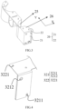
FIG. 3 is a first perspective view of a mounting bracket according to some embodiments of the present disclosure, andFIG. 4 is a second perspective diagram of a circuit board according to some embodiments of the present disclosure. Referring toFIGS. 1 to 4 , the mounting portion 32 may include afirst mounting portion 321, and themounting bracket 20 may have afirst mounting surface 21, where thefirst mounting portion 321 may be attached to thefirst mounting surface 21. - In some embodiments of the present disclosure, the
first mounting portion 321 may be attached to thefirst mounting surface 21 to increase a contact area between thefirst mounting portion 321 and thefirst mounting surface 21, thereby improving the stability of mounting thecell 10 and preventing thecell 10 from loosening or falling off. - In some embodiments of the present disclosure, referring to
FIGS. 1 to 4 , the mounting portion 32 may further include asecond mounting portion 322 adjacent to thefirst mounting portion 321, and themounting bracket 20 may further have asecond mounting surface 22 adjacent to thefirst mounting surface 21, and thesecond mounting portion 322 is attached to thefirst mounting surface 21. - In some embodiments of the present disclosure, the
second mounting portion 321 is attached to thefirst mounting surface 21 to increase a contact area between thefirst mounting portion 321 and thefirst mounting surface 21, thereby improving the stability of mounting thecell 10 and preventing thecell 10 from loosening or falling off. - In some embodiments of the present disclosure, the shape of the
first mounting portion 321 may be the same as that of thefirst mounting surface 21, so that thefirst mounting portion 321 can be sufficiently contacted with thefirst mounting surface 21, thereby improving the stability of mounting thecell 10. The shape of thesecond mounting portion 322 may be the same as that of thesecond mounting surface 22, so that thesecond mounting portion 322 can be sufficiently contacted with thesecond mounting surface 22, thereby improving the stability of mounting thecell 10. - In some embodiments of the present disclosure, referring to
FIGS. 1 to 4 , thewiring portion 31 and thesecond mounting portion 322 may be flexible printed circuit boards 30 (FPC), and thefirst mounting portion 321 may be an epoxy resin plate (FR4). Thewiring portion 31, thesecond mounting portion 322, and thefirst mounting portion 321 may have a rectangular shape, a circular shape, or the like. The thickness of thefirst mounting portion 321 may be in a range of 1.2mm-2mm. For example, the thickness of thefirst mounting portion 321 may be 1.4mm, 1.5 mm, 1.6mm, 1.7mm, 1.8mm, or the like. - In some embodiments of the present disclosure,
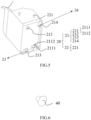
FIG. 5 is a second perspective view of a mounting bracket according to some embodiments of the present disclosure. Referring toFIGS. 4 and5 , a first snap-fit portion 211 may be provided at an edge of thefirst mounting surface 21, and a second snap-fit portion 3211 may be provided at an edge of thefirst mounting portion 321, where the first snap-fit portion 211 may be engaged with the second snap-fit portion 3211. - In some embodiments of the present disclosure, the first snap-
fit portion 211 may be T-shaped, and the second snap-fit portion 3211 may be U-shaped. Engagement of the first snap-fit portion 211 with the second snap-fit portion 3211 may allow the first snap-fit portion 211 and the second snap-fit portion 3211 to be tightly fixed together, thereby improving the stability of the connection therebetween. - In some embodiments of the present disclosure, referring to
FIGS. 1 to 5 , the first snap-fit portion 211 may be provided with a first limitingportion 2111 and a second limitingportion 2112. The first limitingportion 2111 and the second limitingportion 2112 may be disposed in a crossed manner, where the first limitingportion 2111 may be disposed in the first direction and abut the second snap-fit portion 3211 to restrict the second snap-fit portion 3211 from moving in a third direction. The second limitingportion 2112 may be disposed in the third direction and abut the second snap-fit portion 3211 to restrict the second snap-fit portion 3211 from moving in the first direction. The first direction and the third direction may be perpendicular to each other. - Specifically, the first snap-
fit portion 211 may be a T-shaped strip, one side of the T-shaped strip extends in the third direction, another side of the T-shaped strip extends in the first direction, the second snap-fit portion 3211 is a snap-fit groove into which the T-shaped strip is engaged. - Referring to
FIGS. 1 and3 , the first direction is an X direction, and the third direction is a Z direction. - In some embodiments of the present disclosure,
FIG. 6 is a perspective diagram of a fastener according to some embodiments of the present disclosure. Referring toFIGS. 4 to 6 , the first mountingsurface 21 may be provided with afirst connection hole 212, and the first mountingportion 321 may be provided with asecond connection hole 3212, where thefirst connection hole 212 is in communication with thesecond connection hole 3212, andfasteners 40 are detachably mounted within thefirst connection hole 212 and thesecond connection hole 3212, respectively. - In some embodiments of the present disclosure, the
first connection hole 212 may be a T-shaped or circular through-hole, and the second snap-fit portion 3212 may be a FR4 hot riveting hole. The number of FR4 hot riveting holes may be one, which may be more convenient for an operator to fix the hot riveting hole. At the same time, it is also possible to reduce the manufacturing cost of a product and improve the production efficiency of the product. - In some embodiments of the present disclosure, the
fasteners 40 may be, but are not limited to, threadedfasteners 40, such as bolts, studs, screws, rivets, and the like. Illustratively, referring toFIGS. 4 to 6 , a rivet may be used to connect thefirst connection hole 212 to thesecond connection hole 3212. The mountingbracket 20 and thecircuit board 30 can be fixed by mounting thefasteners 40, thereby fixing the plurality ofcells 10. According to the present disclosure, the rivets are used to fix the mountingbracket 20 and thecircuit board 30 to facilitate an operator to disassembly the mountingbracket 20 and thecircuit board 30, which further facilitates inspection and maintenance of the mountingbracket 20, thecircuit board 30, and thecells 10 and provides an economical and convenient solution for quality detection and after-sales service of a battery pack. - In some embodiments of the present disclosure, referring to
FIGS. 4 and5 , afirst fastening portion 213 may be provided at an edge of the first mountingsurface 21 away from the second mountingportion 322, afirst groove portion 23 may be provided between thefirst fastening portion 213 and the first mountingsurface 21, and the first mountingportion 321 may be engaged into thefirst groove portion 23. - In some embodiments of the present disclosure, the
first fastening portion 213 may be a 7-shaped snap-fit portion, which may have a simple, easy-to-use and reliable fastening performance, and thefirst groove portion 23 can be provided between thefirst fastening portion 213 and the first mountingsurface 21, so that the first mountingportion 321 and thefirst groove portion 23 are fixed together quickly and conveniently. - In some embodiments of the present disclosure, referring to
FIGS. 1 ,4 and5 , asecond fastening portion 214 may be provided at a second edge of the first mountingsurface 21 adjacent to the first edge, thesecond groove portion 24 may be provided between the second snap-fit portion 214 and the first mountingsurface 21, and the first mountingportion 321 is located in thesecond groove portion 24. - In some embodiments of the present disclosure, referring to
FIGS. 1 ,4 and5 , thesecond fastening portion 214 may be a 7-shaped snap-fit portion, which may have a simple, easy-to-use and reliable fastening performance, and thesecond groove portion 24 can be provided between thesecond fastening portion 214 and the first mountingsurface 21, so that the first mountingportion 321 and thesecond groove portion 24 are fixed together quickly and conveniently. - In some embodiments of the present disclosure, referring to
FIGS. 1 ,4 , and5 , thefirst fastening portion 213 may be fastened in the Z direction, and thesecond fastening portion 214 may be fastened in the X direction, so that the mounting portion 32 and the mountingbracket 20 are fixed firmly with each other. Of course,FIGS. 1 ,4 , and5 are only schematic illustrations of thefirst fastening portion 213 and thesecond fastening portion 214. In other embodiments of the present disclosure, thefirst fastening portion 213 may be fastened in the X direction, and thesecond fastening portion 214 may be fastened in the Z direction, so that the mounting portion 32 and the mountingbracket 20 are fixed firmly. - In some embodiments of the present disclosure, referring to
FIGS. 1 ,4 , and5 , the first mountingportion 321 may be disposed opposite to thefirst fastening portion 213 and/or thesecond fastening portion 214. Specifically, the first mountingportion 321 may be engaged with an inner side of thefirst fastening portion 213 and/or thesecond fastening portion 214 to be attached to the first mountingsurface 21. - In some embodiments of the present disclosure, referring to
FIGS. 1 ,4 and5 , the second mountingsurface 22 may be provided with astud 221, the second mountingportion 322 may be provided with a through-hole 3221, and thestud 221 may be inserted into the through-hole 3221. - In some embodiments of the present disclosure, the number of
studs 221 is equal to the number of through-holes 3221, and a size of an inner diameter of each of thestuds 221 is adapted to that of the inner diameter of corresponding one of the through-holes 3221. Each of thestuds 221 may be inserted into corresponding one of the through-holes 3221, so that the second mountingsurface 22 may be fixed to the first mountingportion 321, and finally the mounting portion 32 and the mountingbracket 20 can be fixed firmly. - In some embodiments of the present disclosure, referring to
FIGS. 1 ,4 , and5 , a plane in which the second mountingportion 322 is located is perpendicular to a plane in which the first mountingportion 321 is located, and the plane in which the first mountingportion 321 is located is perpendicular to a plane in which thewiring portion 31 is located. - In some embodiments of the present disclosure, a plane in which the second mounting
portion 322 is located is perpendicular to a plane in which the first mountingportion 321 is located, so that structures of the second mountingportion 322 and the first mountingportion 321 can be ensured to be stable. The plane in which the first mountingportion 321 is located is perpendicular to the plane in which thewiring portion 31 is located, so that the structures of the first mountingportion 321 and thewiring portion 31 can be ensured to be stable. - In some embodiments of the present disclosure, the mounting
bracket 20 may include anenvelope portion 25 and amount portion 26 connected to theenvelope portion 25, where theenvelope portion 25 is provided at a side portion of thecell 10, and themount portion 26 is mounted at an end portion of thecell 10. Here, theenvelope portion 25 and themount portion 26 are simple in structure, which facilitate installation and maintenance of the collection assembly. - In some embodiments of the present disclosure, the mounting portion 32 may be stacked on the
mount portion 26, so that the mountingbracket 20 and thecircuit board 30 are more compact in structure. - In some embodiments of the present disclosure, the mounting portion 32 may further include a reinforcing
plate 323 and abody plate 324 disposed integrally with thewiring portion 31, where thebody plate 324 is disposed separately from and interconnected with thebody plate 324. The reinforcingplate 323 and thebody plate 324 can improve the structural strength of thecircuit board 30. - Further, in order to better implement the collection assembly of the embodiments of the present disclosure, the present disclosure further provides a battery pack, including the above-described collection assembly. In the present disclosure, the mounting bracket and the circuit board are provided, the mounting bracket is mounted on the cell, and the wiring portion of the circuit board is connected to the cell, so that the mounting bracket and the mounting portion of the circuit board can be detached conveniently, and the collection assembly is not damaged, thereby finally ensuring the firmness of the battery pack.
Claims (15)
- A collection assembly, comprising:a mounting bracket (20) mountable on a cell (10); anda circuit board (30) having a wiring portion (31) and a mounting portion (32), wherein the wiring portion (31) is connectable to the cell (10);wherein the mounting portion (32) is detachably mounted on the mounting bracket (20).
- The collection assembly of claim 1, whereinthe mounting portion (32) comprises a first mounting portion (321); andthe mounting bracket (20) has a first mounting surface (21), and the first mounting portion (321) is attached to the first mounting surface (21).
- The collection assembly of claim 2, whereina first snap-fit portion (211) is provided at an edge of the first mounting surface (21), and a second snap-fit portion (3211) is provided at an edge of the first mounting portion (321); andthe first snap-fit portion (211) is engaged with the second snap-fit portion (3211).
- The collection assembly of claim 3, whereinthe first snap-fit portion (211) is provided with a first limiting portion (2111) and a second limiting portion (2112); andthe first limiting portion (2111) and the second limiting portion (2112) are disposed in a crossed manner, wherein the first limiting portion (2111) abuts the second snap-fit portion (3211) in a first direction, and the second limiting portion (2112) abuts the second snap-fit portion (3211) in a third direction perpendicular to the first direction.
- The collection assembly of claim 4, wherein the first snap-fit portion (211) is a T-shaped strip, one side of the T-shaped strip extends in the third direction, another side of the T-shaped strip extends in the first direction, and the second snap-fit portion (3211) is a snap-fit groove into which the T-shaped strip is engaged.
- The collection assembly of any one of claims 2-5, whereinthe first mounting surface (21) is provided with a first connection hole (212), and the first mounting portion (321) is provided with a second connection hole (3212); andthe first connection hole (212) is in communication with the second connection hole (3212), and fasteners (40) are detachably mounted within the first connection hole (212) and the second connection hole (3212), respectively.
- The collection assembly of any one of claims 2-6, wherein a first fastening portion (213) is provided at a first edge of the first mounting surface (21), a first groove portion (23) is provided between the first fastening portion (213) and the first mounting surface (21), and the first mounting portion (321) is engaged into the first groove portion (23).
- The collection assembly of claim 7, wherein a second fastening portion (214) is provided at a second edge of the first mounting surface (21) adjacent to the first edge, and a second groove portion (24) is provided between the second fastening portion (214) and the first mounting surface (21), and the first mounting portion (321) is located within the second groove portion (24).
- The collection assembly of any one of claims 2-8, wherein the mounting portion (32) further comprises a second mounting portion (322) adjacent to the first mounting portion (321); and
the mounting bracket (20) further has a second mounting surface (22) adjacent to the first mounting surface (21), and the second mounting portion (322) is attached to the second mounting surface (22). - The collection assembly of claim 9, wherein the second mounting surface (22) is provided with a stud (221), the second mounting portion (322) is provided with a through-hole (3221), and the stud (221) is inserted into the through-hole (3221).
- The collection assembly of claim 9, wherein a plane in which the second mounting portion (322) is located is perpendicular to a plane in which the first mounting portion (321) is located, and a plane in which the first mounting portion (321) is located is perpendicular to a plane in which the wiring portion (31) is located.
- The collection assembly of any one of claims 1-11, wherein the mounting bracket (20) is mounted on the cell in a first direction; and
the wiring portion (31) is mounted on the cell (10) in a second direction perpendicular to the first direction. - The collection assembly of any one of claims 1-12, wherein the mounting bracket (20) comprises an envelope portion (25) and a mount portion (26) connected to the envelope portion (25), the envelope portion (25) is provided at a side portion of the cell (10), and the mount portion (26) is provided at an end portion of the cell (10); and the mounting portion (32) is stacked on the mount portion (26).
- The collection assembly of any one of claims 1-13, wherein the mounting portion (32) further comprises a reinforcing plate (323) and a body plate (324), the body plate (324) is disposed integrally with the wiring portion (31), and the reinforcing plate (323) is disposed separately from and interconnected with the body plate (324).
- A battery pack, comprising: the collection assembly of any one of claims 1-14.
Applications Claiming Priority (2)
| Application Number | Priority Date | Filing Date | Title |
|---|---|---|---|
| CN202323005286.6U CN221080111U (en) | 2023-11-07 | 2023-11-07 | Collection components and battery packs |
| PCT/CN2024/097776 WO2025097758A1 (en) | 2023-11-07 | 2024-06-06 | Collection assembly and battery pack |
Publications (1)
| Publication Number | Publication Date |
|---|---|
| EP4553949A1 true EP4553949A1 (en) | 2025-05-14 |
Family
ID=93432257
Family Applications (1)
| Application Number | Title | Priority Date | Filing Date |
|---|---|---|---|
| EP24211044.3A Pending EP4553949A1 (en) | 2023-11-07 | 2024-11-06 | Collection assembly and battery pack |
Country Status (2)
| Country | Link |
|---|---|
| US (1) | US20250149718A1 (en) |
| EP (1) | EP4553949A1 (en) |
Citations (3)
| Publication number | Priority date | Publication date | Assignee | Title |
|---|---|---|---|---|
| US20140162089A1 (en) * | 2005-09-20 | 2014-06-12 | Metabowerke Gmbh | Rechargeable Battery Pack and Electrical Hand Tool Device |
| US20210226292A1 (en) * | 2018-05-04 | 2021-07-22 | Robert Bosch Gmbh | Rechargeable battery pack |
| CN221080111U (en) * | 2023-11-07 | 2024-06-04 | 惠州亿纬锂能股份有限公司 | Collection components and battery packs |
-
2024
- 2024-11-06 EP EP24211044.3A patent/EP4553949A1/en active Pending
- 2024-11-07 US US18/939,558 patent/US20250149718A1/en active Pending
Patent Citations (3)
| Publication number | Priority date | Publication date | Assignee | Title |
|---|---|---|---|---|
| US20140162089A1 (en) * | 2005-09-20 | 2014-06-12 | Metabowerke Gmbh | Rechargeable Battery Pack and Electrical Hand Tool Device |
| US20210226292A1 (en) * | 2018-05-04 | 2021-07-22 | Robert Bosch Gmbh | Rechargeable battery pack |
| CN221080111U (en) * | 2023-11-07 | 2024-06-04 | 惠州亿纬锂能股份有限公司 | Collection components and battery packs |
Also Published As
| Publication number | Publication date |
|---|---|
| US20250149718A1 (en) | 2025-05-08 |
Similar Documents
| Publication | Publication Date | Title |
|---|---|---|
| EP3799153B1 (en) | Output electrode assembly and battery module | |
| KR20220075404A (en) | battery packs and vehicles | |
| CN221080111U (en) | Collection components and battery packs | |
| CN210805889U (en) | Battery tray, battery package and vehicle | |
| CN215527850U (en) | Battery module casing, battery module and battery package | |
| EP4553949A1 (en) | Collection assembly and battery pack | |
| CN220692286U (en) | Output electrode base and battery pack | |
| CN221009037U (en) | Battery pack and unmanned aerial vehicle | |
| CN218182436U (en) | Signal acquisition device of battery module, battery module and power battery package | |
| CN210723172U (en) | Low-voltage plug-in fixing structure and battery module | |
| CN222212807U (en) | Sampling support and sampling assembly | |
| CN220456577U (en) | Large-module power battery aluminum row limiting structure | |
| CN219497998U (en) | Battery CCS assembly | |
| CN223023529U (en) | CCS assembly and battery module | |
| CN221783353U (en) | Battery packs and electrical equipment | |
| CN222191043U (en) | Battery box, battery and energy storage equipment | |
| EP4583243A1 (en) | Ccs component, battery with same, and electric apparatus | |
| CN223651520U (en) | Energy storage battery module | |
| CN221596663U (en) | Battery pack | |
| CN222802022U (en) | Transition piece for battery module and battery module | |
| CN221304930U (en) | CCS integrated busbar for battery pack module and battery pack module | |
| CN224204136U (en) | A detachable double-layer BMS structure, battery housing, and battery pack. | |
| CN213109077U (en) | Portable battery module support fixing seat for battery replacement | |
| CN223898508U (en) | An energy storage device | |
| CN223006895U (en) | Battery pack |
Legal Events
| Date | Code | Title | Description |
|---|---|---|---|
| PUAI | Public reference made under article 153(3) epc to a published international application that has entered the european phase |
Free format text: ORIGINAL CODE: 0009012 |
|
| STAA | Information on the status of an ep patent application or granted ep patent |
Free format text: STATUS: REQUEST FOR EXAMINATION WAS MADE |
|
| 17P | Request for examination filed |
Effective date: 20241106 |
|
| AK | Designated contracting states |
Kind code of ref document: A1 Designated state(s): AL AT BE BG CH CY CZ DE DK EE ES FI FR GB GR HR HU IE IS IT LI LT LU LV MC ME MK MT NL NO PL PT RO RS SE SI SK SM TR |