EP4553938A1 - Battery monomer, battery and electric device - Google Patents
Battery monomer, battery and electric device Download PDFInfo
- Publication number
- EP4553938A1 EP4553938A1 EP23918991.3A EP23918991A EP4553938A1 EP 4553938 A1 EP4553938 A1 EP 4553938A1 EP 23918991 A EP23918991 A EP 23918991A EP 4553938 A1 EP4553938 A1 EP 4553938A1
- Authority
- EP
- European Patent Office
- Prior art keywords
- wall
- insulating member
- battery cell
- battery
- segment
- Prior art date
- Legal status (The legal status is an assumption and is not a legal conclusion. Google has not performed a legal analysis and makes no representation as to the accuracy of the status listed.)
- Pending
Links
Images



Classifications
-
- H—ELECTRICITY
- H01—ELECTRIC ELEMENTS
- H01M—PROCESSES OR MEANS, e.g. BATTERIES, FOR THE DIRECT CONVERSION OF CHEMICAL ENERGY INTO ELECTRICAL ENERGY
- H01M50/00—Constructional details or processes of manufacture of the non-active parts of electrochemical cells other than fuel cells, e.g. hybrid cells
- H01M50/50—Current conducting connections for cells or batteries
- H01M50/572—Means for preventing undesired use or discharge
- H01M50/584—Means for preventing undesired use or discharge for preventing incorrect connections inside or outside the batteries
- H01M50/59—Means for preventing undesired use or discharge for preventing incorrect connections inside or outside the batteries characterised by the protection means
-
- H—ELECTRICITY
- H01—ELECTRIC ELEMENTS
- H01M—PROCESSES OR MEANS, e.g. BATTERIES, FOR THE DIRECT CONVERSION OF CHEMICAL ENERGY INTO ELECTRICAL ENERGY
- H01M10/00—Secondary cells; Manufacture thereof
- H01M10/04—Construction or manufacture in general
-
- H—ELECTRICITY
- H01—ELECTRIC ELEMENTS
- H01M—PROCESSES OR MEANS, e.g. BATTERIES, FOR THE DIRECT CONVERSION OF CHEMICAL ENERGY INTO ELECTRICAL ENERGY
- H01M10/00—Secondary cells; Manufacture thereof
- H01M10/04—Construction or manufacture in general
- H01M10/0481—Compression means other than compression means for stacks of electrodes and separators
-
- H—ELECTRICITY
- H01—ELECTRIC ELEMENTS
- H01M—PROCESSES OR MEANS, e.g. BATTERIES, FOR THE DIRECT CONVERSION OF CHEMICAL ENERGY INTO ELECTRICAL ENERGY
- H01M50/00—Constructional details or processes of manufacture of the non-active parts of electrochemical cells other than fuel cells, e.g. hybrid cells
- H01M50/10—Primary casings; Jackets or wrappings
- H01M50/102—Primary casings; Jackets or wrappings characterised by their shape or physical structure
-
- H—ELECTRICITY
- H01—ELECTRIC ELEMENTS
- H01M—PROCESSES OR MEANS, e.g. BATTERIES, FOR THE DIRECT CONVERSION OF CHEMICAL ENERGY INTO ELECTRICAL ENERGY
- H01M50/00—Constructional details or processes of manufacture of the non-active parts of electrochemical cells other than fuel cells, e.g. hybrid cells
- H01M50/10—Primary casings; Jackets or wrappings
- H01M50/102—Primary casings; Jackets or wrappings characterised by their shape or physical structure
- H01M50/103—Primary casings; Jackets or wrappings characterised by their shape or physical structure prismatic or rectangular
-
- H—ELECTRICITY
- H01—ELECTRIC ELEMENTS
- H01M—PROCESSES OR MEANS, e.g. BATTERIES, FOR THE DIRECT CONVERSION OF CHEMICAL ENERGY INTO ELECTRICAL ENERGY
- H01M50/00—Constructional details or processes of manufacture of the non-active parts of electrochemical cells other than fuel cells, e.g. hybrid cells
- H01M50/10—Primary casings; Jackets or wrappings
- H01M50/116—Primary casings; Jackets or wrappings characterised by the material
- H01M50/124—Primary casings; Jackets or wrappings characterised by the material having a layered structure
- H01M50/1245—Primary casings; Jackets or wrappings characterised by the material having a layered structure characterised by the external coating on the casing
-
- H—ELECTRICITY
- H01—ELECTRIC ELEMENTS
- H01M—PROCESSES OR MEANS, e.g. BATTERIES, FOR THE DIRECT CONVERSION OF CHEMICAL ENERGY INTO ELECTRICAL ENERGY
- H01M50/00—Constructional details or processes of manufacture of the non-active parts of electrochemical cells other than fuel cells, e.g. hybrid cells
- H01M50/50—Current conducting connections for cells or batteries
- H01M50/543—Terminals
-
- H—ELECTRICITY
- H01—ELECTRIC ELEMENTS
- H01M—PROCESSES OR MEANS, e.g. BATTERIES, FOR THE DIRECT CONVERSION OF CHEMICAL ENERGY INTO ELECTRICAL ENERGY
- H01M50/00—Constructional details or processes of manufacture of the non-active parts of electrochemical cells other than fuel cells, e.g. hybrid cells
- H01M50/50—Current conducting connections for cells or batteries
- H01M50/572—Means for preventing undesired use or discharge
- H01M50/584—Means for preventing undesired use or discharge for preventing incorrect connections inside or outside the batteries
- H01M50/588—Means for preventing undesired use or discharge for preventing incorrect connections inside or outside the batteries outside the batteries, e.g. incorrect connections of terminals or busbars
-
- H—ELECTRICITY
- H01—ELECTRIC ELEMENTS
- H01M—PROCESSES OR MEANS, e.g. BATTERIES, FOR THE DIRECT CONVERSION OF CHEMICAL ENERGY INTO ELECTRICAL ENERGY
- H01M2220/00—Batteries for particular applications
- H01M2220/20—Batteries in motive systems, e.g. vehicle, ship, plane
-
- H—ELECTRICITY
- H01—ELECTRIC ELEMENTS
- H01M—PROCESSES OR MEANS, e.g. BATTERIES, FOR THE DIRECT CONVERSION OF CHEMICAL ENERGY INTO ELECTRICAL ENERGY
- H01M50/00—Constructional details or processes of manufacture of the non-active parts of electrochemical cells other than fuel cells, e.g. hybrid cells
- H01M50/50—Current conducting connections for cells or batteries
- H01M50/572—Means for preventing undesired use or discharge
- H01M50/584—Means for preventing undesired use or discharge for preventing incorrect connections inside or outside the batteries
- H01M50/59—Means for preventing undesired use or discharge for preventing incorrect connections inside or outside the batteries characterised by the protection means
- H01M50/593—Spacers; Insulating plates
-
- Y—GENERAL TAGGING OF NEW TECHNOLOGICAL DEVELOPMENTS; GENERAL TAGGING OF CROSS-SECTIONAL TECHNOLOGIES SPANNING OVER SEVERAL SECTIONS OF THE IPC; TECHNICAL SUBJECTS COVERED BY FORMER USPC CROSS-REFERENCE ART COLLECTIONS [XRACs] AND DIGESTS
- Y02—TECHNOLOGIES OR APPLICATIONS FOR MITIGATION OR ADAPTATION AGAINST CLIMATE CHANGE
- Y02E—REDUCTION OF GREENHOUSE GAS [GHG] EMISSIONS, RELATED TO ENERGY GENERATION, TRANSMISSION OR DISTRIBUTION
- Y02E60/00—Enabling technologies; Technologies with a potential or indirect contribution to GHG emissions mitigation
- Y02E60/10—Energy storage using batteries
Definitions
- the present application relates to the technical field of batteries, in particular to a battery cell, battery, and electric device.
- the embodiments of the present application provide a battery cell, a battery, and an electric device, which can effectively improve the assembly quality and stability of the battery.
- the present application provides a battery cell, including a housing, an electrode assembly, and an insulating member; the housing includes a first wall; the electrode assembly is accommodated within the housing; the insulating member is covered on an outer side of the housing and covers an outer surface of the first wall that is away from the electrode assembly in a thickness direction of the first wall, wherein the insulating member is provided with a first hollow region; along the thickness direction of the first wall, the first hollow region is positioned on a side of the first wall that is away from the electrode assembly; the first wall forms a first exposed region at a position corresponding to the first hollow region; and the first exposed region is configured for connecting with a compression strip.
- the outer surface of the housing is covered with an insulating member, which allows the insulating member to insulate and isolate the housing of the battery cell from the external environment, thereby reducing the risk of short circuits during the use of the battery cell.
- a first exposed region is formed on the first wall of the housing, enabling the battery cell to connect with the compression strip through the first exposed region. Therefore, when the battery cell is assembled into a battery, the compression strip can connect directly with the housing, which enables the housing to be connected indirectly to the compression strip without the need for an insulating member.
- an area of the first exposed region is S, satisfying a condition: S ⁇ 50 mm 2 .
- the area of the first exposed region of the first wall, which is configured for connecting with the compression strip is set to be greater than or equal to 50 mm 2 . This facilitates an increase in the connection area between the first wall and the compression strip, thereby enhancing the connection strength.
- a minimum distance between the first exposed region and an edge of the first wall is D 1 , satisfying a condition: 1 mm ⁇ D 1 ⁇ 5 mm.
- the minimum distance between the first exposed region and the edge of the first wall is from 1 mm to 5 mm.
- it can alleviate the phenomenon the distance between the first hollow region and the edge of the first wall is too small, which makes it difficult to manufacture the first hollow region; thus, the difficulty of manufacturing battery cells is reduced.
- it can alleviate the phenomenon of excessive insulating member covering the first wall due to the large distance between the first hollow region and the edge of the first wall, which results in a smaller area of the first exposed region formed on the first wall.
- the housing further includes a second wall and a side wall; along the thickness direction of the first wall, the second wall is arranged opposite to the first wall, and the side wall is arranged around the first wall and the second wall;
- the insulating member includes a first insulating member and a second insulating member which are separately provided, wherein the first insulating member covers an outer surface of the first wall away from the electrode assembly, and the second insulating member covers an outer surface of the second wall away from the electrode assembly and an outer surface of the side wall away from the electrode assembly.
- the insulating member as a separately arranged first insulating member and second insulating member, where the first insulating member is a structure that covers the first wall and the second insulating member is a structure that covers the side wall and the second wall, the first insulating member and second insulating member of the insulating member correspond to the first wall of the housing and the second wall and the side wall of the housing, respectively. This facilitates a reduction in the assembly difficulty between the insulating member and the housing.
- the first hollow region is provided on the first insulating member.
- the structure of the insulating member is simple, facilitating processing and manufacturing, and ensuring that the first hollow region and the second insulating member do not affect each other, which is beneficial for reducing the assembly difficulty of the battery cell.
- the second insulating member is provided with a flange portion, wherein the flange portion is arranged along a circumferential direction of the first wall and is located on a side of the first wall away from the electrode assembly.
- the flange portion and the edge of the first insulating member jointly enclose to form the first hollow region.
- the second insulating member is provided with a flange portion arranged on the first wall along the circumferential direction of the first wall and located at the edge of the first wall, such that the edge of the first insulating member arranged on the first wall and a portion of the flange portion jointly enclose to form the first hollow region, thereby forming a first exposed region on the first wall.
- a portion of the flange portion is located between the first wall and the first insulating member.
- the first insulating member can press the portion of the flange portion against the first wall, which is beneficial for improving the connection stability of the flange portion of the second insulating member on the first wall, thus reducing the occurrence of the flange portion falling off.
- the first insulating member and the flange portion jointly enclose to form two first hollow regions; and along the first direction, the two first hollow regions are respectively located at the two ends of the first insulating member.
- the first direction is perpendicular to the thickness direction of the first wall.
- the arrangement allows the first wall to connect with the compression strip through the two first exposed regions, which is beneficial for further enhancing the connection strength between the housing and the compression strip.
- the interference effect with the first insulating member can be reduced, thereby lowering the assembly difficulty between the battery cell and the compression strip.
- the flange portion includes a first segment, a second segment, a third segment, and a fourth segment connected sequentially along the circumferential direction of the first wall.
- the first segment is arranged opposite the third segment, and along the second direction, the second segment is arranged opposite the fourth segment, wherein the first direction, the second direction, and the thickness direction of the first wall are mutually perpendicular.
- the first insulating member is located between the first segment and the third segment in the first direction.
- the first segment, a portion of the second segment, a portion of the fourth segment, and one end of the first insulating member in the first direction are jointly enclosed to form one of the first hollow regions.
- the third segment, a portion of the second segment, a portion of the fourth segment, and the other end of the first insulating member in the first direction are jointly enclosed to form another one of the first hollow regions.
- the flange portion is provided with a first segment, a second segment, a third segment, and a fourth segment that are connected sequentially along the circumferential direction of the first wall, where the first segment and the third segment are arranged opposite each other in the first direction, and the second segment and the fourth segment are arranged opposite each other in the second direction, making the flange portion a rectangular ring structure.
- the second wall and the side wall are an integrally molded structure, wherein, along the thickness direction of the first wall, one end of the side wall is connected to the second wall, and the other end encloses to form an opening.
- the first wall is an end cap to close the opening.
- the housing is assembled from two components.
- the structure of the housing facilitates covering the second insulating member of the insulating member over the outer surface of the integrally-formed second wall and side wall, which is beneficial for reducing the assembly difficulty of the battery cell.
- the battery cell further includes an electrode terminal; the electrode terminal is provided on the first wall and is electrically connected to the electrode assembly.
- the insulating member is provided with a mounting hole. The electrode terminal passes through the mounting hole, and the mounting hole is arranged at intervals with the first hollow region.
- the electrode terminal is provided on the first wall, and the insulating member is provided with a mounting hole corresponding to the position of the electrode terminal, which allows the electrode terminal to pass through.
- the mounting hole and the first hollow region are arranged at intervals, on one hand, the first exposed region formed corresponding to the first hollow region on the first wall can be arranged at intervals with the electrode terminal, so as to reduce interference with the electrode terminal when the first exposed region is connected to external components; and on the other hand, it ensures that the insulating member is not communicated between the first hollow region and the mounting hole, thereby allowing the insulating member to be sleeved on the electrode terminal to enhance the connection reliability of the insulating member.
- a minimum distance between the first hollow region and the mounting hole is D 2 , satisfying a condition: D 2 ⁇ 0.5 mm.
- the minimum dimension of a portion of the insulating member between the first hollow region and the mounting hole is greater than or equal to 0.5 mm, thereby alleviating the risk of fracture due to the dimension of the portion of the insulating member between the first hollow region and the mounting hole being too small.
- the insulating member is provided with two first hollow regions arranged along the first direction, so as to form two first exposed regions arranged along the first direction on the first wall.
- the first direction is perpendicular to the thickness direction of the first wall.
- the first wall is provided with two electrode terminals.
- the two electrode terminals are arranged along the first direction, and the two electrode terminals are located between the two first hollow regions.
- the minimum distance between each first hollow region and the adjacent mounting hole is D 2 .
- the insulating member is provided with two first hollow regions arranged along the first direction; and two electrode terminals are arranged on the first wall along the first direction and are located between the two first hollow regions. This ensures that the minimum distance between the first hollow region and the adjacent mounting hole is D 2 . Thus, by setting the minimum size of D 2 , the risk of fracture occurring in the portion of the insulating member located in the first direction between the first exposed region and the electrode terminal during use can be reduced.
- the insulating member is provided with two first hollow regions arranged along the first direction, so as to form two first exposed regions arranged along the first direction on the first wall.
- the first direction is perpendicular to the thickness direction of the first wall.
- the electrode terminal is located between the two first exposed regions.
- the housing further includes a second wall, where the second wall is arranged opposite the first wall along the thickness direction of the first wall.
- the battery cell further includes two electrode terminals, with the two electrode terminals provided on the first wall and the second wall respectively. The two electrode terminals are electrically connected to the electrode assembly.
- the first wall can be provided with more space to form the first exposed region, and the difficulty of arranging the first hollow region of the insulating member can be reduced.
- the housing further includes a second wall, where the second wall is arranged opposite the first wall along the thickness direction of the first wall.
- the insulating member is further provided with a second hollow region; along the thickness direction of the first wall, the second hollow region is positioned on a side of the second wall that is away from the electrode assembly; the second wall forms a second exposed region at a position corresponding to the second hollow region; and the second exposed region is configured for connecting with a box.
- the first hollow region and the second hollow region are distributed and arranged at the positions of the insulating member corresponding to both sides of the first wall and the second wall, meaning that the insulating member is provided with the first hollow region and the second hollow region, which are respectively on the opposite sides of the housing along the thickness direction of the first wall, the first exposed region and the second exposed region are formed on the first wall and the second wall of the housing, respectively.
- first wall and the second wall of the housing to connect with the compression strip and the box respectively through the first exposed region and the second exposed region, enhances the structural stability of the battery cell when assembled into the box, and allows the housing to connect directly with the box, to reduce the phenomenon of easy detachment due to the indirect connection between the housing and the box through the insulating member.
- the embodiments of the present application also provide a battery, including the above-mentioned battery cell.
- the battery further includes a box and a compression strip, where both the compression strip and the battery cell are accommodated within the box, and the first exposed region is bonded to the compression strip.
- the battery is provided with a box and a compression strip.
- the compression strip By bonding the compression strip to the first exposed region of the housing of the battery cell, the battery cell is fixed within the box of the battery.
- the structure of the battery allows the housing of the battery cell to bond directly to the compression strip, which enables the housing to be connected indirectly to the compression strip without the need for an insulating member. This helps to reduce the impact of the insulating member on the bonding effectiveness between the battery cell and the compression strip and can effectively enhance the bonding strength, so as to reduce the phenomenon of easy detachment due to indirect bonding between the housing and the compression strip through the insulating member. Therefore, the structural stability of the battery cell when assembled into the box is enhanced, which lowers the risk of shaking or detachment of the battery cell during use and improves the assembly quality and usage stability of the battery.
- the battery includes multiple battery cells, and the compression strip bonds to the first exposed regions of the multiple battery cells.
- the box is therein provided with multiple battery cells, and the compression strip is bonded to the first exposed regions of the multiple battery cells, thus connecting multiple battery cells into a single unit through the compression strip. It is beneficial for enhancing the structural strength and the structural stability of multiple battery cells within the box, further improving the usage stability of the battery.
- the housing further includes a second wall, where the second wall is arranged opposite the first wall along the thickness direction of the first wall.
- the insulating member is further provided with a second hollow region; along the thickness direction of the first wall, the second hollow region is positioned on a side of the second wall that is away from the electrode assembly; the second wall forms a second exposed region at a position corresponding to the second hollow region; and the second exposed region is bonded to the box.
- the battery cell is further fixed within the box.
- the structure of the battery allows the housing of the battery cell to bond directly to the box, which enables the housing to be connected indirectly to the box without the need for an insulating member. This helps to reduce the impact of the insulating member on the bonding effectiveness between the battery cell and the box and can effectively enhance the bonding strength. Therefore, the structural stability of the battery cell when assembled into the box is enhanced, which lowers the risk of shaking or detachment of the battery cell during use and improves the assembly quality and usage stability of the battery.
- the embodiments of the present application further provide an electric device comprising the battery as described above.
- the term “multiple” refers to two or more (including two).
- the battery cell can be a secondary battery, where the secondary battery refers to a battery cell that can be recharged to activate the active material and continue to be used after the battery cell has been discharged.
- the battery cell can include lithium-ion batteries, sodium-ion batteries, sodium-lithium-ion batteries, lithium metal batteries, sodium metal batteries, lithium-sulfur batteries, magnesium-ion batteries, nickel-metal hydride batteries, nickel-cadmium batteries, lead-acid batteries, etc.
- the embodiment of the present application is not limited herein.
- the battery cell generally includes an electrode assembly.
- the electrode assembly includes a positive electrode, a negative electrode, and a separator.
- active ions such as lithium ions
- the separator is arranged between the positive electrode and the negative electrode, which can prevent short circuits between the positive and negative electrodes and allow active ions to pass through.
- the positive electrode can be a positive electrode sheet, and the positive electrode sheet can include a positive electrode current collector and positive electrode active material arranged on at least one surface of the positive electrode current collector.
- the positive electrode current collector comprises two surfaces opposite each other in its thickness direction, and the positive electrode active material is provided on either or both of the two surfaces opposite the positive electrode current collector.
- the positive electrode current collector can be made of a metal foil or composite current collector.
- a metal foil materials such as aluminum or stainless steel with silver surface treatment, stainless steel, copper, aluminum, nickel, carbon electrode, carbon, nickel, or titanium can be used.
- the composite current collector can include a polymer material base layer and a metal layer.
- the composite current collector can be formed by forming metallic materials (aluminum, aluminum alloys, nickel, nickel alloys, titanium, titanium alloys, silver and silver alloys, etc.) onto a base material of polymeric material (e.g., substrates of polypropylene, polyethylene terephthalate, polybutylene terephthalate, polystyrene, polyethylene, etc.).
- the positive electrode active material can comprise at least one of the following materials: a lithium-containing phosphate, a lithium transition metal oxide, and respective modified compounds thereof.
- a lithium-containing phosphate a lithium-containing phosphate
- a lithium transition metal oxide a lithium transition metal oxide
- respective modified compounds thereof a lithium-containing phosphate, a lithium transition metal oxide, and respective modified compounds thereof.
- the present application is not limited to these materials, and other conventional materials that can be utilized as positive electrode active material for battery cathodes can also be used.
- These positive electrode active materials can be used in only one alone or in a combination of more than two.
- lithium-containing phosphate can comprise, but are not limited to, at least one of a composite of lithium iron phosphate (e.g., LiFePO 4 , also referred to as LFP), lithium iron phosphate, and carbon; a composite of lithium manganese phosphate (e.g., LiMnPO 4 ), lithium manganese phosphate, and carbon; and a composite of lithium ferromanganese phosphate, lithium manganese iron phosphate, and carbon.
- a composite of lithium iron phosphate e.g., LiFePO 4 , also referred to as LFP
- LiMnPO 4 lithium manganese phosphate
- LiMnPO 4 lithium manganese phosphate
- the negative electrode can be a negative electrode sheet, and the negative electrode sheet can include a negative electrode current collector.
- the negative electrode current collector can be made of a metal foil, foam metal, or composite current collector.
- a metal foil materials such as aluminum or stainless steel with silver surface treatment, stainless steel, copper, aluminum, nickel, carbon electrode, carbon, nickel, or titanium can be used.
- Foam metals can be nickel foam, copper foam, aluminum foam, foam alloys, or carbon foam.
- the composite current collector can include a polymer material base layer and a metal layer.
- the composite current collector can be formed by forming metallic materials (copper, copper alloys, nickel, nickel alloys, titanium, titanium alloys, silver and silver alloys, etc.) onto a base material of polymeric material (e.g., substrates of polypropylene, polyethylene terephthalate, polybutylene terephthalate, polystyrene, polyethylene, etc.).
- metallic materials copper, copper alloys, nickel, nickel alloys, titanium, titanium alloys, silver and silver alloys, etc.
- a base material of polymeric material e.g., substrates of polypropylene, polyethylene terephthalate, polybutylene terephthalate, polystyrene, polyethylene, etc.
- the negative electrode sheet can include a negative electrode current collector and a negative electrode active material provided on at least one surface of the negative electrode current collector.
- the negative electrode current collector comprises two surfaces opposite each other in its thickness direction, and the negative electrode active material is provided on either or both of the two surfaces opposite the negative electrode current collector.
- the negative electrode active material can be a negative electrode active material known in the art for use in the battery cells.
- the negative electrode active material can comprise at least one of the following materials: artificial graphite, natural graphite, soft carbon, hard carbon, silicon-based materials, tin-based materials, and lithium titanate.
- the material of the positive electrode current collector can be aluminum and the material of the negative electrode current collector can be copper.
- the electrode assembly further comprises an isolation member, and the isolation member is provided between the positive electrode and the negative electrode.
- the isolation member is a separator.
- the present application does not impose specific restrictions on the type of separator and allows for the selection of any well-known porous structure separator with good chemical and mechanical stability.
- the main material of the separator can be selected from at least one of glass fiber, nonwoven fabric, polyethylene, polypropylene, polyvinylidene fluoride, and ceramic.
- the isolation member is a solid electrolyte.
- the solid electrolyte is arranged between the positive electrode and the negative electrode and serves both to transport ions and to isolate the positive and negative electrodes.
- the battery cell also includes an electrolyte, and the electrolyte conducts ions between the positive and negative electrodes.
- the present application does not impose specific restrictions on the type of electrolyte and allows for selection based on requirements.
- the electrolyte can be in a liquid state, gel state, or solid state.
- the electrode assembly is of a wound structure.
- the positive electrode sheet and the negative electrode sheet are wound into a wound structure.
- the electrode assembly is of a stacked structure.
- the electrode assembly can have shapes such as cylindrical, flat, or prismatic.
- the electrode assembly is provided with a tab, and the tab can conduct current out from the electrode assembly.
- the tab includes a positive tab and a negative tab.
- the battery cell can include a housing.
- the housing is configured to encapsulate the electrode assembly, electrolyte, and other components.
- the housing can be made of materials such as steel, aluminum, plastic (e.g., polypropylene), composite metal (e.g., copper-aluminum composite housing), or aluminum-plastic film.
- the battery cell can be cylindrical battery cells, prismatic battery cells, soft pouch battery cells, or battery cells of other shapes.
- the prismatic cells include square battery cells, blade battery cells, and multi-prismatic battery cells; and the multi-prismatic battery cells can be, for example, hexagonal battery cells.
- the present application is not particularly limited herein.
- the batteries mentioned in the embodiments of the present application refer to a single physical module that comprises one or multiple battery cells to provide higher voltage and capacity.
- the battery can be a battery module.
- the multiple battery cells are arranged and fixed to form a module.
- the battery can be a battery pack, and the battery pack includes a box and a battery cell, wherein the battery cell or the battery module is housed within the box.
- the box can be of a portion of the chassis structure of the vehicle.
- a portion of the box can be at least a portion of the floor of the vehicle, or a portion of the box can be at least a portion of the crossbeam and longitudinal beam of the vehicle.
- the battery can be an energy storage device.
- the energy storage device includes storage containers, energy storage cabinets, and the like.
- Batteries have prominent advantages such as high energy density, low environmental pollution, high power density, long service life, broad applicability, and low self-discharge coefficient. They are an important component of the current development of new energy sources.
- the housing of the battery cell usually includes a shell and an end cap, with the end cap covering the opening of the shell.
- the electrode terminal is typically assembled onto the end cap of the battery cell so that when the end cap is covered on the shell, the electrode terminal, the current collector member, and the tab can be stacked and welded to the tab to each other; and this achieves an electrical connection between the electrode terminal and the electrode assembly. Therefore, the electrode terminal serves as the output terminal of the battery cell to enable the input or output of electrical energy of the battery cell; and finally, the end cap is then attached to the shell.
- a battery typically contains multiple battery cells, and the multiple battery cells are arranged in groups within the box of the battery.
- a blue film is often applied on the outer side of the shell of the housing, and a top cover patch is arranged on the end cap of the housing, thus ensuring insulation and isolation between a battery cell and other battery cells.
- the multiple battery cells can be assembled into a single unit. This increases the overall structural strength of the assembled group of multiple battery cells, thereby enhancing the stability and reliability of the battery during use.
- the structural adhesive is blocked by the top cover patch, resulting in the compression strip not being bonded directly to the end cap. Therefore, a top cover patch is arranged between the compression strip and the end cap, causing the compression strip and the end cap to be indirectly-bonded structures through the top cover patch.
- connection strength between the top cover patch and the end cap cannot meet the connection strength of the compression strip bonding on the battery cell, in the process of assembling multiple battery cells into a group, the bonding between the battery cell and the compression strip could be unreliable.
- the pulling effect of the compression strip can cause the top cover patch to detach from the end cap, resulting in the separation of the compression strip from the battery cell. This, in turn, leads to poorer assembly quality and usage stability of the battery.
- the inventor in order to solve the problem of poor assembly quality and usage stability of the battery, the inventor, after in-depth research, designed a battery cell, wherein the battery cell includes a housing, an electrode assembly, and an insulating member.
- the housing includes a first wall.
- the electrode assembly is housed within the housing.
- the insulating member is covered on an outer side of the housing and covers an outer surface of the first wall that is away from the electrode assembly in a thickness direction of the first wall.
- the insulating member is further provided with a first hollow region; along the thickness direction of the first wall, the first hollow region is positioned on a side of the first wall that is away from the electrode assembly; the first wall forms a first exposed region at a position corresponding to the first hollow region; and the first exposed region is configured for connecting with a compression strip.
- the outer surface of the housing is covered with an insulating member, which allows the insulating member to insulate and isolate the housing of the battery cell from the external environment, thereby reducing the risk of short circuits during the use of the battery cell.
- a first exposed region is formed on the first wall of the housing, enabling the battery cell to connect with the compression strip through the first exposed region. Therefore, when the battery cell is assembled into a battery, the compression strip can connect directly with the housing, which enables the housing to be connected indirectly to the compression strip without the need for an insulating member.
- the battery cell disclosed in the embodiments of the present application can be used in various electric devices, including but not limited to vehicles, ships, or aircraft.
- a power system of the electrical device can be constructed using the battery cell, the battery, and other components disclosed in the present application. In this way, it is helpful to alleviate the problem that the battery cells are not securely assembled in the process of assembling multiple battery cells into a group, so as to improve the assembly quality and use stability of the battery.
- the embodiments of the present application provide an electric device that uses batteries as a power source.
- the electric device can comprise, but is not limited to, mobile phones, tablets, laptops, electric toys, power tools, electric bicycles, electric cars, boats, spacecraft, and more.
- the electric toys can include stationary or mobile electric toys, for example, video game consoles, electric car toys, electric boat toys, and electric airplane toys.
- the spacecraft can include aircraft, rockets, space shuttles, and spacecraft, among others.
- the electric device is a vehicle 1000 as an example.
- FIG. 1 is a schematic diagram of a structure of a vehicle 1000 provided in some embodiments of the present application.
- the vehicle 1000 can be a gasoline-powered car, a natural gas car, or a new energy vehicle.
- the new energy vehicles can be pure electric cars, hybrid cars, extended-range cars, and so on.
- the vehicle 1000 is therein provided with a battery 100, and the battery 100 can be provided at the bottom of the vehicle 1000, at the head of the vehicle 1000, or at the rear of the vehicle 1000.
- the battery 100 is configured to provide power for the vehicle 1000.
- the battery 100 can serve as an operational power source or a power source for the use of the vehicle 1000.
- the vehicle 1000 also comprises a controller 200 and a motor 300.
- the controller 200 is configured to manage the supply of power from the battery 100 to the motor 300, for example, for working power requirements for starting, navigating, and driving the vehicle 1000.
- the battery 100 serves not only as the operational power source or the power source for use of the vehicle 1000 but also as the driving power source for the vehicle 1000. It can replace or partially substitute for conventional fuels like gasoline or natural gas to provide driving propulsion for the vehicle 1000.
- FIG. 2 is a section view of a battery 100 provided in some embodiments of the present application
- FIG. 3 is a structural schematic diagram of a battery cell 20 provided in some embodiments of the present application.
- the battery 100 comprises a box 10 and a battery cell 20, wherein the box 20 is configured to contain the battery cell 10.
- the box 10 is configured to provide an assembly space for the battery cell 20, and the box 10 can be of various structures.
- the box 10 can comprise a first box body 11 and a second box body 12, wherein the first box bod 11 and the second box body 12 are caped together.
- the first box body 11 and the second box body 12 collectively define an assembly space configured for accommodating the battery cell 20.
- the second box body 12 can be a hollow structure open at one end, and the first box body 11 can be a plate-like structure.
- the first box body 11 is capped over an open side of the second box body 12 so that the first box body 11 and the second box body 12 together define an assembly space.
- both the first box body 11 and the second box body 12 can be hollow structures open at one end, and an open side of the first box body 11 is capped over an open side of the second box body 12.
- the box 10 formed by the first box body 11 and the second box body 12 can be of a variety of shapes, such as cylindrical or rectangular. Exemplarily, in FIG. 2 , the box 10 is rectangular in shape.
- one or multiple battery cells 20 can be provided inside the box 10.
- the multiple battery cells 20 can be connected in series, parallel, or hybrid.
- a hybrid connection refers to having both series and parallel connections among multiple battery cells 20.
- the multiple battery cells 20 can be directly connected in series, parallel, or hybrid. Then, the whole comprising the multiple battery cells 20 is housed in the box 10.
- the battery 100 can also be in the form that, the multiple battery cells 20 are first connected in series, parallel, or hybrid to form battery modules, and then the multiple battery modules are connected in series, parallel, or hybrid to be formed into a whole, which is then accommodated within the box 10.
- the battery 100 can also include other structures.
- the battery 100 can also include a busbar component, and the busbar component is configured for connecting multiple battery cells 20, so as to achieve electrical connections between the multiple battery cells 20.
- Each battery cell 20 can be a secondary battery or a primary battery; and it can also be a lithium-sulfur battery, sodium-ion battery, magnesium-ion battery, or other types, but is not limited herein.
- the battery cell 20 can have various shapes such as cylindrical, flat, rectangular, or other shapes. Exemplarily, in FIG. 3 , the battery cell 20 is of a cylindrical structure.
- the battery 100 can also include a compression strip 30.
- the battery 100 includes multiple battery cells 20, with the compression strip 30 arranged inside the box 10.
- the compression strip 30 is configured to connect to the multiple battery cells 20, thus fastening the multiple battery cells 20 into a single unit. This helps to reduce the occurrence of shaking or collisions among the multiple battery cells 20 within the box 10.
- one end of the battery cell 20 in the thickness direction X of the first wall is bonded to the bottom of the box 10, meaning that one end of the battery cell 20 in the thickness direction X of the first wall is bonded to the bottom surface of the second box body 12 facing the first box body 11, and the other end is bonded to the compression strip 30.
- the compression strip 30 is bonded to multiple battery cells 20, thus enabling the multiple battery cells 20 housed inside the box 10 to form a single unit. This improves the overall structural strength of the battery 100, so as to reduce the risk of the battery cells 20 shaking or colliding with each other during use.
- the battery cell 20 can be placed in the box 10 upright or upside-down.
- the bottoms of the battery cells 20 are typically bonded to the bottom of the box 10, and the compression strip 30 is bonded to the top of the battery cells 20.
- the tops of the battery cells 20 are typically bonded to the top of the box 10, and the compression strip 30 is bonded to the bottoms of the battery cells 20.
- the battery cells 20 are placed upright in the box 10.
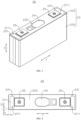
- FIG. 4 is a top view of a battery cell 20 provided in some embodiments of the present application
- FIG. 5 is a schematic diagram of a structure of a battery cell 20 (after removing an insulating member 23) provided in some embodiments of the present application.
- the present application provides a battery cell 20, wherein the battery cell 20 includes a housing 21, an electrode assembly 22, and an insulating member 23.
- the housing 21 includes a first wall 211.
- the electrode assembly 22 is housed within the housing 21.
- the insulating member 23 is covered on an outer side of the housing 21 and covers an outer surface of the first wall 211 which is away from the electrode assembly 22 in a thickness direction X of the first wall.
- the insulating member 23 is further provided with a first hollow region 231; along the thickness direction X of the first wall, the first hollow region 231 is positioned on a side of the first wall 211 that is away from the electrode assembly 22; the first wall 211 forms a first exposed region 2111 at a position corresponding to the first hollow region 231; and the first exposed region 2111 is configured for connecting with a compression strip 30.
- the housing 21 can also be configured to contain an electrolyte, such as an electrolytic solution.
- the housing 21 can be of various structural forms, such as cylinder or cuboid. Similarly, the material of the housing 21 can also be diverse, including copper, iron, aluminum, steel, aluminum alloy, and more.
- the housing 21 can further include a second wall 212 and a side wall 213.
- the second wall 212 is arranged opposite to the first wall 211 in the thickness direction X of the first wall.
- the side wall 213 surrounds the second wall 212.
- the side wall 213 and the second wall 212 are integrally molded, so that one end of the side wall 213 is connected to the second wall 212, and the other end encloses an opening 2131 opposite the second wall 212.
- the side wall 213 and the second wall 212 together form a shell with an accommodating cavity.
- the accommodating cavity is configured for housing the electrode assembly 22 and the accommodating cavity is provided with the opening 2131.
- the side wall 213 and the second wall 212 form a hollow structure with the opening 2131 at one end.
- the first wall 211 covers the opening 2131 of the side wall 213, meaning that the first wall 211 is the end cap of the housing 21 configured for sealing the opening 2131.
- the first wall 211 covers the opening 2131 of the side wall 213 to form a hermetical connection, thus forming a sealed space configured for accommodating the electrode assembly 22 and the electrolyte.
- the first exposed region 2111 is formed on the end cap of the housing 21.
- the side wall 213 can also be integrally molded with the first wall 211.
- the second wall 212 is the end cap that seals the opening 2131, meaning that the first exposed region 2111 is formed on the bottom wall, opposite to the end cap, of the shell of the housing 21.
- the housing 21 is not limited to the above structure, and the housing 21 can also be other structures.
- the housing 21 can include a separately arranged first wall 211, second wall 212, and side wall 213.
- the side wall 213 encloses and forms a hollow structure with two opposing openings 2131.
- the first wall 211 and the second wall 212 are respectively covered over one of the openings 2131 of the side wall 213, thus forming hermetical connections. This forms a sealed space configured for accommodating the electrode assembly 22 and the electrolyte.
- the electrode assembly 22 can first be placed into the shell formed by the side wall 213 and the second wall 212, and then electrolyte can be filled into the shell, after which the first wall 211 is capped over the opening 2131 of the shell to complete the assembly of the battery cell 20.
- the housing 21 can have various shapes, such as a cylindrical structure, a rectangular cuboid, or a prismatic structure.
- the shape of the housing 21 can be determined based on the specific shape of the electrode assembly 22. For example, if the electrode assembly 22 is of a cylindrical structure, the housing 21 of a cylindrical structure can be selected; if the electrode assembly 22 is of a rectangular structure, the housing 21 of a rectangular structure can be selected. Exemplarily, in FIG. 3 , the housing 21 is of a cylindrical structure.
- the electrode assembly 22 is a component within the battery cell 20 where electrochemical reactions occur.
- the electrode assembly 22 can include a positive electrode sheet, a negative electrode sheet, and a separator.
- the structure of the electrode assembly 22 can be various.
- the electrode assembly 22 can be a wound structure formed by winding a positive electrode sheet, a separator, and a negative electrode sheet; or a layered structure formed by layering a positive electrode sheet, a separator, and a negative electrode sheet.
- one or multiple electrode assemblies 22 can be accommodated within the housing 21. Exemplarily, in FIG. 2 , two electrode assemblies 22 are provided, and the two electrode assemblies 22 are arranged in a stacking manner along their thickness directions.
- the insulating member 23 is covered on an outer side of the housing 21 and covers an outer surface of the first wall 211 which is away from the electrode assembly 22 in a thickness direction X of the first wall. In other words, the insulating member 23 is wrapped around the entire outer surface of the housing 21 such that the first wall 211 of the housing 21 is covered by the insulating member 23.
- the material of the insulating member 23 can be varied, such as rubber, silicone, or rubber.
- the insulating member 23 is bonded to the outer surface of the housing 21.
- the first wall 211 forms a first exposed region 2111 at the location corresponding to the first hollow region 231, meaning that the insulating member 23 is provided with the first hollow region 231 so as to allow the first wall 211 of the housing 21 to have a region that is avoided by the first hollow region 231. Therefore, a first exposed region 2111 on the first wall 211, which is not covered by the insulating member 23, is formed.
- one or more first hollow regions 231 can be provided on the insulating member 23.
- the insulating member 23 is provided with two first hollow regions 231.
- the two first hollow regions 231 are arranged at intervals along the first direction Y, thus forming two first exposed regions 2111 that are arranged at intervals along the first direction Y on the first wall 211.
- the first direction Y is perpendicular to the thickness direction X of the first wall, which increases the bonding strength between the first wall 211 and the compression strip 30.
- the number of first hollow regions 231 can also be one, three, four or five, etc.
- the first hollow region 231 is rectangular, and correspondingly, the first exposed region 2111 formed on the first wall 211 is also rectangular.
- the first hollow region 231 can be of various shapes, such as triangular, pentagonal, circular, or elliptical.
- first exposed region 2111 is configured for connection with the compression strip 30, and the connection method between the first exposed region 2111 and the compression strip 30 can be diverse, such as bonding or welding. Exemplarily, in the embodiments of the present application, the first exposed region 2111 is configured for bonding with the compression strip 30.
- the battery cell 20 can also include a pressure relief mechanism 24, wherein the pressure relief mechanism 24 is mounted on the housing 21.
- the pressure relief mechanism 24 is configured to release the internal pressure of the battery cell 20 when the internal pressure or the temperature of the battery cell 20 reaches a predetermined value.
- the pressure relief mechanism 24 can be arranged on the first wall 211 of the housing 21, on the second wall 212 of the housing 21, or on the side wall 213 of the housing 21.
- the pressure relief mechanism 24 is arranged on the first wall 211.
- the insulating member 23 is provided with an avoidance opening 232 configured to avoid the pressure relief mechanism 24, thus allowing the pressure relief mechanism 24 to discharge the internal pressure of the battery cell 20.
- the pressure relief mechanism 24 can be various pressure relief components such as explosion-proof valves, burst discs, gas valves, relief valves, or safety valves.
- the outer surface of the housing 21 is covered with an insulating member 23, which allows the insulating member 23 to insulate and isolate the housing 21 of the battery cell 20 from the external environment, thereby reducing the risk of short circuits during the use of the battery cell 20.
- an insulating member 23 By arranging the first hollow region 231 at the position corresponding to one side of the first wall 211 of the insulating member 23, a first exposed region 2111 is formed on the first wall 211 of the housing 21, enabling the battery cell 20 to connect with the compression strip 30 through the first exposed region 2111. Therefore, when the battery cell 20 is assembled into a battery 100, the compression strip 30 can connect directly with the housing 21, which enables the housing 21 to be connected indirectly to the compression strip 30 without the need for an insulating member 23.
- an area of the first exposed region 2111 is S, satisfying a condition: S ⁇ 50mm 2 .
- the area of the region on the first wall 211 corresponding to a first hollow region 231 that is not covered by the insulating member 23 is greater than or equal to 50 mm 2 .
- the area of the first exposed region 2111 of the first wall 211, which is configured for connecting with the compression strip 30, is greater than or equal to 50 mm 2 , sufficient area is ensured for mutual connection between the first wall 211 and the compression strip 30. This facilitates an increase in the connection area between the first wall 211 and the compression strip 30, thereby enhancing the connection strength.
- a minimum distance between the first exposed region 2111 and an edge of the first wall 211 is D 1 , satisfying a condition: 1 mm ⁇ D 1 ⁇ 5 mm.
- the minimum distance between the first exposed region 2111 and the edge of the first wall 211 is between 1 mm and 5 mm
- the minimum distance between the first hollow region 231 arranged on the insulating member 23 and the edge of the first wall 211 is from 1 mm to 5 mm.
- it can alleviate the phenomenon where the distance between the first hollow region 231 and the edge of the first wall 211 is too small, which makes it difficult to manufacture the first hollow region 231; thus, the difficulty of manufacturing the battery cells 20 is reduced.
- the housing 21 further includes a second wall 212 and a side wall 213.
- the second wall 212 is arranged opposite to the first wall 211, and the side wall 213 is arranged around the first wall 211 and the second wall 212.
- the insulating member 23 includes a first insulating member 233 and a second insulating member 234 that are separately provided, wherein the first insulating member 233 covers an outer surface of the first wall 211 away from the electrode assembly 22, and the second insulating member 234 covers an outer surface of the second wall 212 away from the electrode assembly 22 and the outer surface of the side wall 213 away from the electrode assembly 22.
- the second wall 212 is arranged opposite to the first wall 211, and the side wall 213 is arranged around the first wall 211 and the second wall 212.
- the first wall 211 and the second wall 212 are arranged at intervals along the thickness direction X of the first wall and are respectively arranged at the two ends of the side wall 213.
- the side wall 213 is arranged around the circumference of the first wall 211 along the circumferential direction of the first wall 211 and around the circumference of the second wall 212 along the circumferential direction of the second wall 212.
- the structure of the housing 21 can be of various types, such as a structure where the first wall 211, the second wall 212, and the side wall 213 are all separate structures; it can also be a structure where the second wall 212 and the side wall 213 are integrally molded, with the first wall 211 connected to the end of the side wall 213 that is far from the first wall 211; or it can be a structure where the first wall 211 and the side wall 213 are integrally molded, with the second wall 212 connected to the end of the side wall 213 that is far from the second wall 212.
- the first insulating member 233 covers the outer surface of the first wall 211 away from the electrode assembly 22, meaning that the first insulating member 233 is arranged on the first wall 211 and is located on the side of the first wall 211 away from the interior of the battery cell 20.
- the second insulating member 234 covers the outer surface of the second wall 212 away from the electrode assembly 22 and the outer surface of the side wall 213 away from the electrode assembly 22, meaning that the second insulating member 234 is arranged on the shell formed by enclosing the second wall 212 and the side wall 213 and is located on the side of the shell away from the interior of the battery cell 20.
- the insulating member as a separately arranged first insulating member 233 and second insulating member 234, where the first insulating member 233 is a structure that covers the first wall 211 and the second insulating member 234 is a structure that covers the side wall 213 and the second wall 212, the first insulating member 233 and the second insulating member 234 of the insulating member 23 correspond to the first wall 211 of the housing 21 and the second wall 212 and the side wall 213 of the housing 21, respectively. This facilitates a reduction in the assembly difficulty between the insulating member 23 and the housing 21.
- FIG. 6 is a schematic diagram of a structure of a first insulating member 233 of a battery cell 20 provided in some embodiments of the present application.
- the first hollow region 231 is provided on the first insulating member 233.
- the first hollowed region 231 is a through-hole structure provided on the first insulating member 233.
- the first hollowed region 231 penetrates the first insulating member 233 along the thickness direction X of the first wall, thereby forming the first exposed region 2111 on the first wall 211.
- the minimum distance D 1 between the first exposed region 2111 and the edge of the first wall 211 is from 1mm to 5mm
- the first insulating member 233 covers the surface of the first wall 211 away from the electrode assembly 22, and the first hollowed region 231 is arranged on the first insulating member 233
- the minimum distance D 1 between the first exposed region 2111 and the edge of the first wall 211 is the minimum distance between the first hollowed region 231 and the edge of the first insulating member 233. That is, the minimum distance between the first hollowed region 231 and the edge of the first insulating member 233 is from 1mm to 5mm.
- the structure of the insulating member 23 is simple, facilitating processing and manufacturing, and ensuring that the first hollow region 231 and the second insulating member 234 do not affect each other, which is beneficial for reducing the assembly difficulty of the battery cell 20.
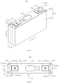
- FIG. 7 is a schematic diagram of a structure of a battery cell 20 provided in some embodiments of the present application
- FIG. 8 is a top view of a battery cell 20 provided in other embodiments of the present application
- FIG. 9 is a schematic diagram of a structure of a battery cell 20 (after removing a first insulating member 233) provided in some embodiments of the present application.
- the second insulating member 234 is provided with a flange portion 2341, wherein the flange portion 2341 is arranged along a circumferential direction of the first wall 211 and is located on a side of the first wall 211 away from the electrode assembly 22.
- the flange portion 2341 and the edge of the first insulating member 233 jointly enclose to form the first hollow region 231.
- the second insulating member 234 is provided with a flange portion 2341, and the flange portion 2341 is arranged along a circumferential direction of the first wall 211 and is located on a side of the first wall 211 away from the electrode assembly 22.
- the portion of the second insulating member 234 provided on the outer side of the shell formed by enclosing the second wall 212 and the side wall 213 is folded onto the first wall 211, so that the second insulating member 234 forms the flanged portion 2341 located on the outer surface of the first wall 211.
- the flange portion 2341 is an annular structure extending along the circumferential direction of the first wall 211.
- the minimum distance D 1 between the first exposed region 2111 and the edge of the first wall 211 is from 1mm to 5mm
- the first hollowed region 231 is a structure formed by enclosing the enclosure of the first insulating member 233 and the flange portion 2341
- the minimum distance D 1 between the first exposed region 2111 and the edge of the first wall 211 is thus the width of the flange portion 2341, which means the width of the flange portion 2341 is from 1mm to 5mm.
- the second insulating member 234 is provided with a flange portion 2341 arranged on the first wall 211 along the circumferential direction of the first wall 211 and located at the edge of the first wall 211, such that the edge of the first insulating member 233 arranged on the first wall 211 and a portion of the flange portion 2341 jointly enclose to form the first hollow region 231, thereby forming a first exposed region 2111 on the first wall 211.
- the battery cell 20 does not need to have the first insulating member 233 configured with a through-hole structure, which helps improve the overall structural strength of the first insulating member 233; and on the other hand, it is beneficial for controlling the size and dimensions of the first hollow region 231.
- a portion of the flange portion 2341 is located between the first wall 211 and the first insulating member 233.
- a portion of the flange portion 2341 is located between the first wall 211 and the first insulating member 233.
- a portion of the first insulating member 233 is arranged on the side of the flange portion 2341 away from the first wall 211 along the thickness direction X of the first wall, so that the first insulating member 233 and the first wall 211 together press the flange portion 2341 tightly.
- the first insulating member 233 is of a rectangular structure
- the flange portion 2341 is a rectangular annular structure.
- the flange portion 2341 includes a first segment 2341a, a second segment 2341b, a third segment 2341c, and a fourth segment 2341d, which are sequentially connected along the circumferential direction of the first wall 211.
- the first segment 2341a and the third segment 2341c are arranged opposite to each other; and along the second direction Z, the second segment 2341b and the fourth segment 2341d are arranged opposite to each other.
- the first direction Y, the second direction Z, and the thickness direction X of the first wall are mutually perpendicular.
- the two ends of the first insulating member 233 along the second direction Z are respectively lapped over the second segment 2341b and the fourth segment 2341d of the flange portion 2341, so as to arrange the flange portion 2341 between the first insulating member 233 and the first wall 211 in the thickness direction X of the first wall.
- the first insulating member 233 can press the portion of the flange portion 2341 against the first wall 211, which is beneficial for improving the connection stability of the flange portion 2341 of the second insulating member 234 on the first wall 211, thus reducing the occurrence of the flange portion 2341 falling off.
- the first insulating member 233 and the flange portion 2341 jointly enclose to form two first hollow regions 231; and along the first direction Y, the two first hollow regions 231 are respectively located at the two ends of the first insulating member 233.
- the first direction Y is perpendicular to the thickness direction X of the first wall.
- the two first hollow regions 231 are respectively located at both ends of the first insulating member 233.
- the dimension of the first insulating member 233 in the first direction Y is smaller than the dimension of the flange portion 2341 in the first direction Y, so that both ends of the first insulating member 233 in the first direction Y can respectively form two first hollow regions 231 with the inner edge of the flange portion 2341.
- the two first hollow regions 231 are positioned at both ends of the first insulating member 233 in the first direction Y.
- two first exposed regions 2111 arranged in the first direction Y are formed on the first wall 211, and the two first exposed regions 2111 are respectively located at the two ends of the first insulating member 233.
- the arrangement allows the first wall 211 to connect with the compression strip 30 through the two first exposed regions 2111, which is beneficial for further enhancing the connection strength between the housing 21 and the compression strip 30.
- the interference effect with the first insulating member 233 can be reduced, thereby lowering the assembly difficulty between the battery cell 20 and the compression strip 30.
- the flange portion 2341 includes a first segment 2341a, a second segment 2341b, a third segment 2341c, and a fourth segment 2341d connected sequentially along the circumferential direction of first wall 211.
- first segment 2341a and the third segment 2341c are arranged opposite to each other, and along the second direction Z, the second segment 2341b and the fourth segment 2341d are arranged opposite to each other.
- the first direction Y, the second direction Z, and the thickness direction X of the first wall are mutually perpendicular.
- the first insulating member 233 is positioned between the first segment 2341a and the third segment 2341c along the first direction Y.
- the first segment 2341a, a portion of the second segment 2341b, a portion of the fourth segment 2341d, and one end of the first insulating member 233 in the first direction Y together enclose to form one first hollow region 231.
- the third segment 2341c, a portion of the second segment 2341b, a portion of the fourth segment 2341d, and the other end of the first insulating member 233 in the first direction Y together enclose to form another first hollow region 231.
- the first segment 2341a is arranged opposite to the third segment 2341c, and along the second direction Z, the second segment 2341b is arranged opposite to the fourth segment 2341d, meaning that the flange portion 2341 of the second insulating member 234 is a rectangular annular structure.
- the first insulating member 233 is positioned between the first segment 2341a and the third segment 2341c along the first direction Y.
- the first segment 2341a, a portion of the second segment 2341b, a portion of the fourth segment 2341d, and one end of the first insulating member 233 in the first direction Y together enclose to form one first hollow region 231.
- the third segment 2341c, a portion of the second segment 2341b, a portion of the fourth segment 2341d, and the other end of the first insulating member 233 in the first direction Y together enclose to form another first hollow region 231.
- the first insulating member 233 is located between the first segment 2341a and the third segment 2341c, and the first insulating member 233 and the first segment 2341a and the third segment 2341c are structures arranged at intervals.
- both ends of the first insulating member 233 overlap with the second segment 2341b and the fourth segment 2341d, respectively, so that the first insulating member 233 covers a portion of the second segment 2341b and a portion of the fourth segment 2341d.
- the flange portion 2341 is provided with a first segment 2341a, a second segment 2341b, a third segment 2341c, and a fourth segment 2341d that are connected sequentially along the circumferential direction of the first wall 211, where the first segment 2341a and the third segment 2341c are arranged opposite each other in the first direction Y, and the second segment 2341b and the fourth segment 2341d are arranged opposite each other in the second direction Z, making the flange portion 2341 a rectangular ring structure.
- the edges of both ends of the first insulating member 233 in the first direction Y can respectively form two first hollow regions 231 with the flange portion 2341, where the structure is simple and easy to implement.
- the second wall 212 and the side wall 213 are an integrally molded structure, wherein, along the thickness direction X of the first wall, one end of the side wall 213 is connected to the second wall 212, and the other end encloses to form an opening 2131.
- the first wall 211 is an end cap to close the opening 2131.
- the second wall 212 and the side wall 213 enclose to form a hollow structure with an opening 2131 at one end along the thickness direction X of the first wall, and the first wall 211 covers the opening 2131, to form a housing 21 configured for accommodating the electrode assembly 22.
- the second wall 212 and the side wall 213 can also be separate structures, that is, the side wall 213 is a hollow structure with openings 2131 at both ends along the thickness direction X of the first wall, and the first wall 211 and the second wall 212 respectively cover the two openings 2131 of the side wall 213.
- the second wall 212 and the side wall 213 are molded as an integrated structure, meaning that the second wall 212 and the side wall 213 of the housing 21 are manufactured through an integrated molding process, such as stamping or casting.
- the housing 21 is assembled from two components.
- the structure of the housing 21 facilitates covering the second insulating member 234 of the insulating member 23 over the outer surface of the integrally-formed second wall 212 and side wall 213, which is beneficial for reducing the assembly difficulty of the battery cell 20.
- FIG. 10 is a schematic diagram of a structure of a first insulating member 233 of a battery cell 20 provided in some embodiments of the present application.
- the battery cell 20 further includes an electrode terminal 25, wherein the electrode terminal 25 is arranged on the first wall 211 and is electrically connected with the electrode assembly 22.
- the insulating member 23 is provided with a mounting hole 235.
- the electrode terminal 25 passes through the mounting hole 235, and the mounting hole 235 is arranged at intervals with the first hollow region 231.
- the mounting hole 235 is arranged at intervals with the first hollow region 231. That is, the electrode terminal 25 provided on the first wall 211 is arranged at intervals with the first hollow region 231, and a portion of the insulating member 23 is positioned between the electrode terminal 25 and the first hollow region 231.
- the electrode terminal 25 is provided on the first wall 211, and the insulating member 23 is provided with a mounting hole 235 corresponding to the position of the electrode terminal 25, which allows the electrode terminal 25 to pass through.
- the mounting hole 235 and the first hollow region 231 are arranged at intervals, on one hand, the first exposed region 2111 formed corresponding to the first hollow region 231 on the first wall 211 can be arranged at intervals with the electrode terminal 25, so as to reduce interference with the electrode terminal 25 when the first exposed region 2111 is connected to external components; and on the other hand, it ensures that the insulating member 23 is not communicated between the first hollow region 231 and the mounting hole 235, thereby allowing the insulating member 23 to be sleeved on the electrode terminal 25 to enhance the connection reliability of the insulating member 23.
- a minimum distance between the first hollow region 231 and the mounting hole 235 is D 2 , satisfying a condition: D 2 ⁇ 0.5 mm.
- the minimum distance between the first hollow region 231 and the mounting hole 235 is D 2 . That is to say, in the arrangement direction of the first hollow region 231 and the mounting hole 235, the minimum dimension of the portion of the first insulating member 233 of the insulating member 23 positioned between the first hollow region 231 and the mounting hole 235 is D 2 .
- the minimum dimension of a portion of the insulating member 23 between the first hollow region 231 and the mounting hole 235 is greater than or equal to 0.5 mm, thereby alleviating the risk of fracture due to the dimension of the portion of the insulating member 23 between the first hollow region 231 and the mounting hole 235 being too small.
- the insulating member 23 is provided with two first hollow regions 231 arranged along the first direction Y, so as to form two first exposed regions 2111 arranged along the first direction Y on the first wall 211.
- the first direction Y is perpendicular to the thickness direction X of the first wall.
- the first wall 211 is provided with two electrode terminals 25.
- the two electrode terminals 25 are arranged along the first direction Y, and the two electrode terminals 25 are located between the two first hollow regions 231.
- the minimum distance between each first hollow region 231 and the adjacent mounting hole 235 is D 2 .
- D 2 is the distance between the first hollow region 231 in the first direction Y and the adjacent mounting hole 235; and in the embodiment where the first insulating member 233 and the flanged portion 2341 of the second insulating member 234 enclose to form the first hollow region, as shown in FIG. 10 , D 2 is the distance between the first hollow region 231 in the first direction Y and the adjacent end of the first insulating member 233.
- the insulating member 23 is provided with two first hollow regions 231 arranged along the first direction Y; and two electrode terminals 25 are arranged on the first wall 211 along the first direction Y and are located between the two first hollow regions 231. This ensures that the minimum distance between the first hollow region 231 and the adjacent mounting hole 235 is D 2 . Thus, by setting the minimum size of D 2 , the risk of fracture occurring in the portion of the insulating member 23 located in the first direction Y between the first exposed region 2111 and the electrode terminal 25 during use can be reduced.
- the insulating member 23 is provided with two first hollow regions 231 arranged along the first direction Y, so as to form two first exposed regions 2111 arranged along the first direction Y on the first wall 211.
- the first direction Y is perpendicular to the thickness direction X of the first wall.
- the electrode terminal 25 is positioned between the two first exposed regions 2111.
- two first hollow regions 231 are located on each side of the two electrode terminals 25 in the first direction Y so that one first hollow region 231, one electrode terminal 25, the other electrode terminal 25, and the other first hollow region 231 are sequentially arranged along the first direction Y.
- Two first hollow regions 231 are arranged along the first direction Y on the insulating member 23 so as to form two first exposed regions 2111 on the first wall 211 along the first direction Y, and the electrode terminal 25 is arranged between the two first exposed regions 2111. On the one hand, it can further enhance the connection strength between the first wall 211 and the compression strip 30 through the two first exposed regions 2111; on the other hand, by arranging the two first exposed regions 2111 on both sides of the electrode terminal 25, the difficulty of connecting the battery cell 20 to the compression strip 30 during grouping can be reduced.
- the battery cell 20 can also be of other structures.
- the housing 21 also includes a second wall 212, and the second wall 212 is arranged opposite to the first wall 211 in the thickness direction X of the first wall.
- the battery cell 20 also includes two electrode terminals 25, and the two electrode terminals 25 are respectively arranged on the first wall 211 and the second wall 212. Both electrode terminals 25 are electrically connected to the electrode assembly 22.
- the two electrode assemblies 22 configured for outputting or inputting the positive electrode and the negative electrode of the battery cell 20 are respectively arranged on both sides of the housing 21 in the thickness direction X of the first wall.
- the electrode terminals 25 can also be arranged on the side wall 213.
- the first wall 211 can be provided with more space to form the first exposed region 2111, and the difficulty of arranging the first hollow region 231 of the insulating member 23 can be reduced.
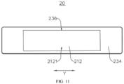
- FIG. 11 is an upward view of a battery cell 20 provided in some embodiments of the present application.
- the housing 21 also includes a second wall 212, and the second wall 212 is arranged opposite to the first wall 211 in the thickness direction X of the first wall.
- the insulating member 23 is further provided with a second hollow region 236; along the thickness direction X of the first wall, the second hollow region 236 is positioned on a side of the second wall 212 that is away from the electrode assembly 22; the second wall 212 forms a second exposed region 2121 at a position corresponding to the second hollow region 236; and the second exposed region 2121 is configured for connecting with a box 10.
- the second wall 212 forms a second exposed region 2121 at the location corresponding to the second hollow region 236, meaning that the insulating member 23 is provided with the second hollow region 236 so as to allow the second wall 212 of the housing 21 to have a region that is avoided by the second hollow region 236. Therefore, a second exposed region 2121 on the second wall 212, which is not covered by the insulating member 23, is formed.
- one or more second hollow regions 236 can be provided on the insulating member 23.
- the insulating member 23 is provided with a second hollow region 236 so as to form a second exposed region 2121 on the second wall 212.
- the number of second hollow regions 236 can also be two, three, four, or five, etc.
- the second hollow region 236 is rectangular, and correspondingly, the second exposed region 2121 formed on the second wall 212 is also rectangular.
- the second hollow region 236 can be of various shapes, such as triangular, pentagonal, circular, or elliptical.
- the second exposed region 2121 is configured for connection with the box 10, and the connection method between the second exposed region 2121 and the box 10 can be diverse, such as bonding or welding. Exemplarily, in the embodiments of the present application, the second exposed region 2121 is configured for bonding with the box 10.
- the second hollow region 236 is arranged on the second insulating member 234.
- the second hollow region 236 is a through hole arranged on the second insulating member 234 and is located on the side of the second wall 212 that is away from the electrode assembly 22.
- the first hollow region 231 and the second hollow region 236 are distributed and arranged at the positions of the insulating member 23 corresponding to both sides of the first wall 211 and the second wall 212, meaning that the insulating member 23 is provided with the first hollow region 231 and the second hollow region 236, which are respectively on the opposite sides of the housing 21 along the thickness direction X of the first wall; and thus, the first exposed region 2111 and the second exposed region 2121 are formed on the first wall 211 and the second wall 212 of the housing 21, respectively.
- first wall 211 and the second wall 212 of the housing 21 to connect with the compression strip 30 and the box 10 respectively through the first exposed region 2111 and the second exposed region 2121, enhances the structural stability of the battery cell 20 when assembled into the box 10, and allows the housing 21 to connect directly with the box 10, to reduce the phenomenon of easy detachment due to the indirect connection between the housing 21 and the box 10 through the insulating member 23.
- the embodiments of the present application provide a battery 100, including the battery cell 20 according to any of the above solutions.
- the battery 100 further includes a box 10 and a compression strip 30, where both the compression strip 30 and the battery cell 20 are accommodated within the box 10, and the first exposed region 2111 is bonded to the compression strip 30.
- the battery cell 20 is placed upright inside the box 10, which means that the second wall 212 of the battery cell 20 is configured to support the electrode assembly 22, so that the second wall 212 can provide support to the electrode assembly 22 in the thickness direction X of the first wall.
- the first wall 211 of the housing 21 is arranged facing the top of the box 10, and the second wall 212 of the housing 21 is arranged facing the bottom of the box 10; or, during actual use, the second wall 212 of the housing 21 is oriented towards the ground or facing downward, making the thickness direction X of the first wall an up-down direction.
- the compression strip 30 is arranged between the first wall 211 and the top of the box 10 in the thickness direction X of the first wall, and the compression strip 30 is bonded to the first exposed region 2111 formed by the first wall 211.
- the compression strip 30 is made of insulating material, and the material of the compression strip 30 can be rubber, plastic, silicone, etc.; and a compression strip 30 with the structure can achieve an insulated connection between the compression strip 30 and the battery cell 20, thus reducing the risk of leakage or short circuit.
- the battery cell 20 can be placed upside down inside the box 10, which means that the first wall 211 of the battery cell 20 is configured to support the electrode assembly 22, so that the first wall 211 can provide support to the electrode assembly 22 in the thickness direction X of the first wall. Therefore, the compression strip 30 is arranged between the first wall 211 and the bottom of the box 10 in the thickness direction X of the first wall, and the compression strip 30 is bonded to the first exposed region 2111 formed by the first wall 211.
- the battery 100 is provided with a box 10 and a compression strip 30.
- the compression strip 30 By bonding the compression strip 30 to the first exposed region 2111 of the housing 21 of the battery cell 20, the battery cell 20 is fixed within the box 10 of the battery 100.
- the structure of the battery 100 allows the housing 21 of the battery cell 20 to bond directly to the compression strip 30, which enables the housing 21 to be connected indirectly to the compression strip 30 without the need for an insulating member 23. This helps to reduce the impact of the insulating member 23 on the bonding effectiveness between the battery cell 20 and the compression strip 30 and can effectively enhance the bonding strength, so as to reduce the phenomenon of easy detachment due to indirect bonding between the housing 21 and the compression strip 30 through the insulating member 23. Therefore, the structural stability of the battery cell 20 when assembled into the box 10 is enhanced, which lowers the risk of shaking or detachment of the battery cell 20 during use and improves the assembly quality and usage stability of the battery 100.
- the battery 100 includes multiple battery cells 20, and the compression strip 30 bonds to the first exposed regions 2111 of the multiple battery cells 20.
- the compression strip 30 is bonded to the first exposed regions 2111 of multiple battery cells 20, which means that one compression strip 30 is configured for bonding with the first exposed regions 2111 of the housings 21 of multiple battery cells 20.
- the box 10 is therein provided with multiple battery cells 20, and the compression strip 30 is bonded to the first exposed regions 2111 of the multiple battery cells 20, thus connecting multiple battery cells 20 into a single unit through the compression strip 30. It is beneficial for enhancing the structural strength and the structural stability of multiple battery cells 20 within the box 10, further improving the usage stability of the battery 100.
- the housing 21 also includes a second wall 212, and the second wall 212 is arranged opposite to the first wall 211 in the thickness direction X of the first wall.
- the insulating member 23 is further provided with a second hollow region 236; along the thickness direction X of the first wall, the second hollow region 236 is positioned on a side of the second wall 212 that is away from the electrode assembly 22; the second wall 212 forms a second exposed region 2121 at a position corresponding to the second hollow region 236; and the second exposed region 2121 is connected to the box 10.
- the battery cell 20 is placed upright within the box 10, so that the second exposed region 2121 formed by the second wall 212 is bonded to the bottom of the box 10. It should be noted that if the battery cell 20 is placed upright within the box 10, the second exposed region 2121 formed by the second wall 212 is then bonded to the top of the box 10.
- the battery cell 20 is further fixed within the box 10.
- the structure of the battery 100 allows the housing 21 of the battery cell 20 to bond directly to the box 10, which enables the housing 21 to be connected indirectly to the box 10 without the need for an insulating member 23. This helps to reduce the impact of the insulating member 23 on the bonding effectiveness between the battery cell 20 and the box 10 and can effectively enhance the bonding strength. Therefore, the structural stability of the battery cell 20 when assembled into the box 10 is enhanced, which lowers the risk of shaking or detachment of the battery cell 20 during use and improves the assembly quality and usage stability of the battery 100.
- the present application provides an electric device, comprising a battery 100 of any of the above solutions, and the battery 100 is configured to provide electrical energy to the electric device.
- the electric device can be any of the above-mentioned devices or systems that apply the battery 100.
- the present application provides a battery cell 20, wherein the battery cell 20 includes a housing 21, an electrode assembly 22, an insulating member 23, and two electrode terminals 25.
- the housing 21 includes a first wall 211, a second wall 212, and a side wall 213.
- the first wall 211 and the second wall 212 are arranged opposite to each other along the thickness direction X of the first wall, and the side wall 213 is arranged around the periphery of the second wall 212 and integrally molded with the second wall 212.
- An end of the side wall 213, away from the second wall 212, forms an opening 2131, and the first wall 211 is an end cap for sealing the opening 2131.
- the electrode assembly 22 is housed within the housing 21.
- the insulating member 23 includes a first insulating member 233 and a second insulating member 234 that are separately provided, wherein the first insulating member 233 covers an outer surface of the first wall 211 away from the electrode assembly 22, and the second insulating member 234 covers an outer surface of the second wall 212 away from the electrode assembly 22 and the outer surface of the side wall 213 away from the electrode assembly 22.
- the first insulating member 233 is provided with two first hollow regions 231 arranged at intervals along the first direction Y, so as to form two first exposed regions 2111 on the first wall 211 at positions corresponding to the two first hollow regions 231.
- the first exposed regions 2111 are configured for bonding with the compression strip 30.
- the second insulating member 234 is provided with a second hollow region 236, and the second wall 212 forms a second exposed region 2121 at a position corresponding to the second hollow region 236.
- the second exposed region 2121 is configured for bonding with the box 10.
- An area of the first exposed region 2111 is S 1 , satisfying a condition: S 1 ⁇ 50 mm 2 .
- the two electrode terminals 25 are arranged on the first wall 211 and electrically connected to the electrode assembly 22. Along the first direction Y, the two electrode terminals 25 are located between the two first exposed regions 2111.
- the first insulating member 233 is provided with mounting holes 235 for the electrode terminals 25 to pass through.
- the minimum distance between each first hollow region 231 and the adjacent mounting hole 235 is D 1 , which satisfies a condition: D 1 ⁇ 0.5 mm.
Landscapes
- Chemical & Material Sciences (AREA)
- Chemical Kinetics & Catalysis (AREA)
- Electrochemistry (AREA)
- General Chemical & Material Sciences (AREA)
- Engineering & Computer Science (AREA)
- Manufacturing & Machinery (AREA)
- Battery Mounting, Suspending (AREA)
- Sealing Battery Cases Or Jackets (AREA)
- Connection Of Batteries Or Terminals (AREA)
- Aviation & Aerospace Engineering (AREA)
Abstract
Description
- The present application relates to the technical field of batteries, in particular to a battery cell, battery, and electric device.
- In recent years, new energy vehicles have experienced a leapfrog development. In the field of electric vehicles, power batteries serve as the energy source for electric vehicles and play an irreplaceable important role. With the strong promotion of new energy vehicles, the demand for power battery products is also increasing. The battery is composed of multiple battery cells stacked together; however, existing batteries exhibit a phenomenon of loose assembly after multiple battery cells are assembled into groups, and the battery cells are prone to the risk of shaking within the battery during use, thus resulting in poor assembly quality and stability of the battery.
- The embodiments of the present application provide a battery cell, a battery, and an electric device, which can effectively improve the assembly quality and stability of the battery.
- In a first aspect, the present application provides a battery cell, including a housing, an electrode assembly, and an insulating member; the housing includes a first wall; the electrode assembly is accommodated within the housing; the insulating member is covered on an outer side of the housing and covers an outer surface of the first wall that is away from the electrode assembly in a thickness direction of the first wall, wherein the insulating member is provided with a first hollow region; along the thickness direction of the first wall, the first hollow region is positioned on a side of the first wall that is away from the electrode assembly; the first wall forms a first exposed region at a position corresponding to the first hollow region; and the first exposed region is configured for connecting with a compression strip.
- In the above technical solution, the outer surface of the housing is covered with an insulating member, which allows the insulating member to insulate and isolate the housing of the battery cell from the external environment, thereby reducing the risk of short circuits during the use of the battery cell. By arranging the first hollow region at the position corresponding to one side of the first wall of the insulating member, a first exposed region is formed on the first wall of the housing, enabling the battery cell to connect with the compression strip through the first exposed region. Therefore, when the battery cell is assembled into a battery, the compression strip can connect directly with the housing, which enables the housing to be connected indirectly to the compression strip without the need for an insulating member. This helps to reduce the impact of the insulating member on the connection effectiveness between the battery cell and the compression strip and can effectively enhance the connection strength, so as to reduce the phenomenon of easy detachment due to indirect connections between the housing and the compression strip through the insulating member. Therefore, while achieving an insulation effect between the battery cell and the external environment, the assembly quality of the battery cell during grouping can be improved, thus benefiting the assembly quality and stability of the battery comprising the battery cells.
- In some embodiments, an area of the first exposed region is S, satisfying a condition: S ≥ 50 mm2.
- In the above technical solution, by setting the area of the first exposed region of the first wall, which is configured for connecting with the compression strip, to be greater than or equal to 50 mm2, the sufficient area is ensured for mutual connection between the first wall and the compression strip. This facilitates an increase in the connection area between the first wall and the compression strip, thereby enhancing the connection strength.
- In some embodiments, a minimum distance between the first exposed region and an edge of the first wall is D1, satisfying a condition: 1 mm ≤ D1 ≤ 5 mm.
- In the above technical solution, by setting the minimum distance between the first exposed region and the edge of the first wall to be between 1 mm and 5 mm, the minimum distance between the first hollow region arranged on the insulating member and the edge of the first wall is from 1 mm to 5 mm. On the one hand, it can alleviate the phenomenon the distance between the first hollow region and the edge of the first wall is too small, which makes it difficult to manufacture the first hollow region; thus, the difficulty of manufacturing battery cells is reduced. On the other hand, it can alleviate the phenomenon of excessive insulating member covering the first wall due to the large distance between the first hollow region and the edge of the first wall, which results in a smaller area of the first exposed region formed on the first wall.
- In some embodiments, the housing further includes a second wall and a side wall; along the thickness direction of the first wall, the second wall is arranged opposite to the first wall, and the side wall is arranged around the first wall and the second wall; the insulating member includes a first insulating member and a second insulating member which are separately provided, wherein the first insulating member covers an outer surface of the first wall away from the electrode assembly, and the second insulating member covers an outer surface of the second wall away from the electrode assembly and an outer surface of the side wall away from the electrode assembly.
- In the above technical solution, by providing the insulating member as a separately arranged first insulating member and second insulating member, where the first insulating member is a structure that covers the first wall and the second insulating member is a structure that covers the side wall and the second wall, the first insulating member and second insulating member of the insulating member correspond to the first wall of the housing and the second wall and the side wall of the housing, respectively. This facilitates a reduction in the assembly difficulty between the insulating member and the housing.
- In some embodiments, the first hollow region is provided on the first insulating member.
- In the above technical solution, by separately providing the first hollow region on the first insulating member to form a first exposed region on the first wall, the structure of the insulating member is simple, facilitating processing and manufacturing, and ensuring that the first hollow region and the second insulating member do not affect each other, which is beneficial for reducing the assembly difficulty of the battery cell.
- In some embodiments, the second insulating member is provided with a flange portion, wherein the flange portion is arranged along a circumferential direction of the first wall and is located on a side of the first wall away from the electrode assembly. The flange portion and the edge of the first insulating member jointly enclose to form the first hollow region.
- In the above technical solution, the second insulating member is provided with a flange portion arranged on the first wall along the circumferential direction of the first wall and located at the edge of the first wall, such that the edge of the first insulating member arranged on the first wall and a portion of the flange portion jointly enclose to form the first hollow region, thereby forming a first exposed region on the first wall. By using the structure, on the one hand, the battery cell does not need to have the first insulating member configured with a through-hole structure, which helps improve the overall structural strength of the first insulating member; on the other hand, it is beneficial for controlling the size and dimensions of the first hollow region.
- In some embodiments, along the thickness direction of the first wall, a portion of the flange portion is located between the first wall and the first insulating member.
- In the above technical solution, by providing the portion of the flange portion of the second insulating member in the thickness direction of the first wall between the first wall and the first insulating member, the first insulating member can press the portion of the flange portion against the first wall, which is beneficial for improving the connection stability of the flange portion of the second insulating member on the first wall, thus reducing the occurrence of the flange portion falling off.
- In some embodiments, the first insulating member and the flange portion jointly enclose to form two first hollow regions; and along the first direction, the two first hollow regions are respectively located at the two ends of the first insulating member. The first direction is perpendicular to the thickness direction of the first wall.
- In the above technical solution, by enclosing the two ends of the first insulating member with the flange portion in the first direction to form two hollow regions, two first exposed regions arranged in the first direction are formed on the first wall, and the two first exposed regions are respectively located at each of the two ends of the first insulating member. On the one hand, the arrangement allows the first wall to connect with the compression strip through the two first exposed regions, which is beneficial for further enhancing the connection strength between the housing and the compression strip. On the other hand, when the first exposed region and the compression strip are connected to each other, the interference effect with the first insulating member can be reduced, thereby lowering the assembly difficulty between the battery cell and the compression strip.
- In some embodiments, the flange portion includes a first segment, a second segment, a third segment, and a fourth segment connected sequentially along the circumferential direction of the first wall. Along the first direction, the first segment is arranged opposite the third segment, and along the second direction, the second segment is arranged opposite the fourth segment, wherein the first direction, the second direction, and the thickness direction of the first wall are mutually perpendicular. The first insulating member is located between the first segment and the third segment in the first direction. The first segment, a portion of the second segment, a portion of the fourth segment, and one end of the first insulating member in the first direction are jointly enclosed to form one of the first hollow regions. The third segment, a portion of the second segment, a portion of the fourth segment, and the other end of the first insulating member in the first direction are jointly enclosed to form another one of the first hollow regions.
- In the above technical solution, the flange portion is provided with a first segment, a second segment, a third segment, and a fourth segment that are connected sequentially along the circumferential direction of the first wall, where the first segment and the third segment are arranged opposite each other in the first direction, and the second segment and the fourth segment are arranged opposite each other in the second direction, making the flange portion a rectangular ring structure. By arranging the first insulating member between the first segment and the third segment in the first direction, the edges of both ends of the first insulating member in the first direction can respectively form two first hollow regions with the flange portion, where the structure is simple and easy to implement.
- In some embodiments, the second wall and the side wall are an integrally molded structure, wherein, along the thickness direction of the first wall, one end of the side wall is connected to the second wall, and the other end encloses to form an opening. The first wall is an end cap to close the opening.
- In the above technical solution, by configuring the second wall of the housing and the side wall as an integrally molded structure, with one end of the side wall away from the second wall forming an opening and the first wall closing the opening, the housing is assembled from two components. The structure of the housing facilitates covering the second insulating member of the insulating member over the outer surface of the integrally-formed second wall and side wall, which is beneficial for reducing the assembly difficulty of the battery cell.
- In some embodiments, the battery cell further includes an electrode terminal; the electrode terminal is provided on the first wall and is electrically connected to the electrode assembly. The insulating member is provided with a mounting hole. The electrode terminal passes through the mounting hole, and the mounting hole is arranged at intervals with the first hollow region.
- In the above technical solution, the electrode terminal is provided on the first wall, and the insulating member is provided with a mounting hole corresponding to the position of the electrode terminal, which allows the electrode terminal to pass through. By arranging the mounting hole and the first hollow region at intervals, on one hand, the first exposed region formed corresponding to the first hollow region on the first wall can be arranged at intervals with the electrode terminal, so as to reduce interference with the electrode terminal when the first exposed region is connected to external components; and on the other hand, it ensures that the insulating member is not communicated between the first hollow region and the mounting hole, thereby allowing the insulating member to be sleeved on the electrode terminal to enhance the connection reliability of the insulating member.
- In some embodiments, a minimum distance between the first hollow region and the mounting hole is D2, satisfying a condition: D2 ≥ 0.5 mm.
- In the above technical solution, by setting the minimum distance between the first hollow region and the mounting hole to be greater than or equal to 0.5 mm, the minimum dimension of a portion of the insulating member between the first hollow region and the mounting hole is greater than or equal to 0.5 mm, thereby alleviating the risk of fracture due to the dimension of the portion of the insulating member between the first hollow region and the mounting hole being too small.
- In some embodiments, the insulating member is provided with two first hollow regions arranged along the first direction, so as to form two first exposed regions arranged along the first direction on the first wall. The first direction is perpendicular to the thickness direction of the first wall. The first wall is provided with two electrode terminals. The two electrode terminals are arranged along the first direction, and the two electrode terminals are located between the two first hollow regions. Along the first direction, the minimum distance between each first hollow region and the adjacent mounting hole is D2.
- In the above technical solution, the insulating member is provided with two first hollow regions arranged along the first direction; and two electrode terminals are arranged on the first wall along the first direction and are located between the two first hollow regions. This ensures that the minimum distance between the first hollow region and the adjacent mounting hole is D2. Thus, by setting the minimum size of D2, the risk of fracture occurring in the portion of the insulating member located in the first direction between the first exposed region and the electrode terminal during use can be reduced.
- In some embodiments, the insulating member is provided with two first hollow regions arranged along the first direction, so as to form two first exposed regions arranged along the first direction on the first wall. The first direction is perpendicular to the thickness direction of the first wall. Along the first direction, the electrode terminal is located between the two first exposed regions.
- In the above technical solution, where two first hollow regions are arranged along the first direction on the insulating member so as to form two first exposed regions on the first wall along the first direction, and the electrode terminal is arranged between the two first exposed regions, one the one hand, it can further enhance the connection strength between the first wall and the compression strip through the two first exposed regions; and on the other hand, by arranging the two first exposed regions on both sides of the electrode terminal, the difficulty of connecting the battery cell to the compression strip during grouping can be reduced.
- In some embodiments, the housing further includes a second wall, where the second wall is arranged opposite the first wall along the thickness direction of the first wall. The battery cell further includes two electrode terminals, with the two electrode terminals provided on the first wall and the second wall respectively. The two electrode terminals are electrically connected to the electrode assembly.
- In the above technical solution, by providing the two electrode terminals of the battery cell on the opposite first wall and second wall of the housing, the first wall can be provided with more space to form the first exposed region, and the difficulty of arranging the first hollow region of the insulating member can be reduced.
- In some embodiments, the housing further includes a second wall, where the second wall is arranged opposite the first wall along the thickness direction of the first wall. The insulating member is further provided with a second hollow region; along the thickness direction of the first wall, the second hollow region is positioned on a side of the second wall that is away from the electrode assembly; the second wall forms a second exposed region at a position corresponding to the second hollow region; and the second exposed region is configured for connecting with a box.
- In the above technical solution, where the first hollow region and the second hollow region are distributed and arranged at the positions of the insulating member corresponding to both sides of the first wall and the second wall, meaning that the insulating member is provided with the first hollow region and the second hollow region, which are respectively on the opposite sides of the housing along the thickness direction of the first wall, the first exposed region and the second exposed region are formed on the first wall and the second wall of the housing, respectively. This enables the first wall and the second wall of the housing to connect with the compression strip and the box respectively through the first exposed region and the second exposed region, enhances the structural stability of the battery cell when assembled into the box, and allows the housing to connect directly with the box, to reduce the phenomenon of easy detachment due to the indirect connection between the housing and the box through the insulating member.
- In a second aspect, the embodiments of the present application also provide a battery, including the above-mentioned battery cell.
- In some embodiments, the battery further includes a box and a compression strip, where both the compression strip and the battery cell are accommodated within the box, and the first exposed region is bonded to the compression strip.
- In the above technical solution, the battery is provided with a box and a compression strip. By bonding the compression strip to the first exposed region of the housing of the battery cell, the battery cell is fixed within the box of the battery. The structure of the battery allows the housing of the battery cell to bond directly to the compression strip, which enables the housing to be connected indirectly to the compression strip without the need for an insulating member. This helps to reduce the impact of the insulating member on the bonding effectiveness between the battery cell and the compression strip and can effectively enhance the bonding strength, so as to reduce the phenomenon of easy detachment due to indirect bonding between the housing and the compression strip through the insulating member. Therefore, the structural stability of the battery cell when assembled into the box is enhanced, which lowers the risk of shaking or detachment of the battery cell during use and improves the assembly quality and usage stability of the battery.
- In some embodiments, the battery includes multiple battery cells, and the compression strip bonds to the first exposed regions of the multiple battery cells.
- In the above technical solution, the box is therein provided with multiple battery cells, and the compression strip is bonded to the first exposed regions of the multiple battery cells, thus connecting multiple battery cells into a single unit through the compression strip. It is beneficial for enhancing the structural strength and the structural stability of multiple battery cells within the box, further improving the usage stability of the battery.
- In some embodiments, the housing further includes a second wall, where the second wall is arranged opposite the first wall along the thickness direction of the first wall. The insulating member is further provided with a second hollow region; along the thickness direction of the first wall, the second hollow region is positioned on a side of the second wall that is away from the electrode assembly; the second wall forms a second exposed region at a position corresponding to the second hollow region; and the second exposed region is bonded to the box.
- In the above technical solution, by bonding the second exposed region of the housing of the battery cell to the box, the battery cell is further fixed within the box. The structure of the battery allows the housing of the battery cell to bond directly to the box, which enables the housing to be connected indirectly to the box without the need for an insulating member. This helps to reduce the impact of the insulating member on the bonding effectiveness between the battery cell and the box and can effectively enhance the bonding strength. Therefore, the structural stability of the battery cell when assembled into the box is enhanced, which lowers the risk of shaking or detachment of the battery cell during use and improves the assembly quality and usage stability of the battery.
- In the third aspect, the embodiments of the present application further provide an electric device comprising the battery as described above.
- To more clearly illustrate the technical solutions of the embodiments of the present application, the following will briefly introduce the drawings used in the embodiments. It should be understood that the following drawings only show some embodiments of the present application, and therefore they should not be regarded as a limitation on the scope. Those ordinary skilled in the art can also obtain other related drawings based on these drawings without inventive effort.
-
FIG. 1 is a schematic diagram of a structure of a vehicle provided in some embodiments of the present application; -
FIG. 2 is a section view of the battery provided in some embodiments of the present application; -
FIG. 3 is a schematic diagram of a structure of a battery cell provided in some embodiments of the present application; -
FIG. 4 is a top view of a battery cell provided in some embodiments of the present application; -
FIG. 5 is a schematic diagram of a structure of a battery cell (after removing an insulating member) provided in some embodiments of the present application; -
FIG. 6 is a schematic diagram of a structure of a first insulating member of a battery cell provided in some embodiments of the present application; -
FIG. 7 is a schematic diagram of a structure of a battery cell provided in some embodiments of the present application; -
FIG. 8 is a top view of the battery cell provided in other embodiments of the present application; -
FIG. 9 is a schematic diagram of a structure of a battery cell (after removing a first insulating member) provided in some embodiments of the present application; -
FIG. 10 is a schematic diagram of a structure of a first insulating member of a battery cell provided in some embodiments of the present application; and -
FIG. 11 is an upward view of a battery cell provided in some embodiments of the present application. - Reference numerals: 1000- vehicle; 100- battery; 10- box; 11- first box body; 12- second box body; 20- battery cell; 21- housing; 211- first wall; 2111- first exposed region; 212- second wall; 2121- second exposed region; 213- side wall; 2131- opening; 22- electrode assembly; 23-insulating member; 231- first hollow region; 232- avoidance opening; 233- first insulating member; 234- second insulating member; 2341- flange portion; 2341a- first segment; 2341b-second segment; 2341c-third segment; 2341d-fourth segment; 235-mounting hole; 236- second hollow region; 24- pressure relief mechanism; 25- electrode terminal; 30- compression strip; 200-controller 300- motor; X- thickness direction of the first wall; Y- first direction; Z- second direction.
- In order to make the objective, technical solution, and advantages of the embodiments of the present application clearer, the following will provide a clear and complete description of the technical solution in the embodiments of the present application, in conjunction with the drawings in the embodiments of the present application. Obviously, the described embodiments are only a part of the embodiments of the present application, rather than all embodiments. Based on the embodiments in the present application, all other embodiments obtained by those of ordinary skill in the art without making inventive efforts are within the scope of protection of the present application.
- Unless otherwise defined, all technical and scientific terms used herein have the same meaning as understood by those skilled in the art of the relevant technical field. The terms used in the summary of the present application are used for the purpose of describing specific embodiments and are not intended to limit the present application. The terms, "comprise", "provide" and their variations, and any other variations, are intended to cover non-exclusive inclusion in the summary, the claims, and the above drawings of the present application. The terms "first", "second", and so on in the summary and claims of the present application or in the above drawings are used to distinguish between different objects and are not intended to describe a specific sequence or hierarchy.
- The term "embodiment" used in the present application means that specific features, structures, or characteristics described in conjunction with the embodiments can be included in at least one embodiment of the present application. The use of the phrase in various parts of the summary does not necessarily refer to the same embodiment, nor does it imply that these embodiments are mutually exclusive or independent of each other.
- In the description of the present application, it should be noted that, unless otherwise clearly stipulated and limited, the terms "provide", "interconnect", "connect", and "attach" should be understood in a broad sense. For example, it can be a fixed connection, a detachable connection, or an integral connection; and it can be a direct connection, an indirect connection through an intermediary, or an internal communication between two components. Those of ordinary skill in the art can understand the meanings of the above terms in the present application according to specific situations.
- In the present application, the term "and/or" is used as a way to describe the relationship between associated objects, indicating that there can be three possible relationships. For example, "A and/or B" can represent: the presence of A, the presence of both A and B, or the presence of B. Additionally, the character "/" in the present application generally represents an "or" relationship between the preceding and following associated objects.
- In the embodiments of the present application, identical reference numerals indicate the same components. For the sake of conciseness, detailed explanations of the same components are omitted in different embodiments. It should be understood that the dimensions such as thickness, length, and width of various components in the embodiments of the present application as shown in the drawings, and the overall dimensions such as thickness, length, and width of the integrated device, are provided as illustrative examples and should not be construed to limit the scope of the present application.
- In the present application, the term "multiple" refers to two or more (including two).
- In the embodiment of the present application, the battery cell can be a secondary battery, where the secondary battery refers to a battery cell that can be recharged to activate the active material and continue to be used after the battery cell has been discharged.
- The battery cell can include lithium-ion batteries, sodium-ion batteries, sodium-lithium-ion batteries, lithium metal batteries, sodium metal batteries, lithium-sulfur batteries, magnesium-ion batteries, nickel-metal hydride batteries, nickel-cadmium batteries, lead-acid batteries, etc. The embodiment of the present application is not limited herein.
- The battery cell generally includes an electrode assembly. The electrode assembly includes a positive electrode, a negative electrode, and a separator. During the charge and discharge process of the battery cell, active ions (such as lithium ions) are embedded and extracted back and forth between the positive electrode and the negative electrode. The separator is arranged between the positive electrode and the negative electrode, which can prevent short circuits between the positive and negative electrodes and allow active ions to pass through.
- In some embodiments, the positive electrode can be a positive electrode sheet, and the positive electrode sheet can include a positive electrode current collector and positive electrode active material arranged on at least one surface of the positive electrode current collector.
- As an example, the positive electrode current collector comprises two surfaces opposite each other in its thickness direction, and the positive electrode active material is provided on either or both of the two surfaces opposite the positive electrode current collector.
- As an example, the positive electrode current collector can be made of a metal foil or composite current collector. For instance, as a metal foil, materials such as aluminum or stainless steel with silver surface treatment, stainless steel, copper, aluminum, nickel, carbon electrode, carbon, nickel, or titanium can be used. The composite current collector can include a polymer material base layer and a metal layer. The composite current collector can be formed by forming metallic materials (aluminum, aluminum alloys, nickel, nickel alloys, titanium, titanium alloys, silver and silver alloys, etc.) onto a base material of polymeric material (e.g., substrates of polypropylene, polyethylene terephthalate, polybutylene terephthalate, polystyrene, polyethylene, etc.).
- As an example, the positive electrode active material can comprise at least one of the following materials: a lithium-containing phosphate, a lithium transition metal oxide, and respective modified compounds thereof. However, the present application is not limited to these materials, and other conventional materials that can be utilized as positive electrode active material for battery cathodes can also be used. These positive electrode active materials can be used in only one alone or in a combination of more than two. The examples of lithium-containing phosphate can comprise, but are not limited to, at least one of a composite of lithium iron phosphate (e.g., LiFePO4, also referred to as LFP), lithium iron phosphate, and carbon; a composite of lithium manganese phosphate (e.g., LiMnPO4), lithium manganese phosphate, and carbon; and a composite of lithium ferromanganese phosphate, lithium manganese iron phosphate, and carbon.
- In some embodiments, the negative electrode can be a negative electrode sheet, and the negative electrode sheet can include a negative electrode current collector.
- For example, the negative electrode current collector can be made of a metal foil, foam metal, or composite current collector. For instance, as a metal foil, materials such as aluminum or stainless steel with silver surface treatment, stainless steel, copper, aluminum, nickel, carbon electrode, carbon, nickel, or titanium can be used. Foam metals can be nickel foam, copper foam, aluminum foam, foam alloys, or carbon foam. The composite current collector can include a polymer material base layer and a metal layer. The composite current collector can be formed by forming metallic materials (copper, copper alloys, nickel, nickel alloys, titanium, titanium alloys, silver and silver alloys, etc.) onto a base material of polymeric material (e.g., substrates of polypropylene, polyethylene terephthalate, polybutylene terephthalate, polystyrene, polyethylene, etc.).
- As an example, the negative electrode sheet can include a negative electrode current collector and a negative electrode active material provided on at least one surface of the negative electrode current collector.
- As an example, the negative electrode current collector comprises two surfaces opposite each other in its thickness direction, and the negative electrode active material is provided on either or both of the two surfaces opposite the negative electrode current collector.
- As an example, the negative electrode active material can be a negative electrode active material known in the art for use in the battery cells. As an example, the negative electrode active material can comprise at least one of the following materials: artificial graphite, natural graphite, soft carbon, hard carbon, silicon-based materials, tin-based materials, and lithium titanate.
- In some embodiments, the material of the positive electrode current collector can be aluminum and the material of the negative electrode current collector can be copper.
- In some implementations, the electrode assembly further comprises an isolation member, and the isolation member is provided between the positive electrode and the negative electrode.
- In some embodiments, the isolation member is a separator. The present application does not impose specific restrictions on the type of separator and allows for the selection of any well-known porous structure separator with good chemical and mechanical stability.
- As an example, the main material of the separator can be selected from at least one of glass fiber, nonwoven fabric, polyethylene, polypropylene, polyvinylidene fluoride, and ceramic.
- In some embodiments, the isolation member is a solid electrolyte. The solid electrolyte is arranged between the positive electrode and the negative electrode and serves both to transport ions and to isolate the positive and negative electrodes.
- In some embodiments, the battery cell also includes an electrolyte, and the electrolyte conducts ions between the positive and negative electrodes. The present application does not impose specific restrictions on the type of electrolyte and allows for selection based on requirements. The electrolyte can be in a liquid state, gel state, or solid state.
- In some embodiments, the electrode assembly is of a wound structure. The positive electrode sheet and the negative electrode sheet are wound into a wound structure.
- In some embodiments, the electrode assembly is of a stacked structure.
- In some embodiments, the electrode assembly can have shapes such as cylindrical, flat, or prismatic.
- In some embodiments, the electrode assembly is provided with a tab, and the tab can conduct current out from the electrode assembly. The tab includes a positive tab and a negative tab.
- In some embodiments, the battery cell can include a housing. The housing is configured to encapsulate the electrode assembly, electrolyte, and other components. The housing can be made of materials such as steel, aluminum, plastic (e.g., polypropylene), composite metal (e.g., copper-aluminum composite housing), or aluminum-plastic film.
- As an example, the battery cell can be cylindrical battery cells, prismatic battery cells, soft pouch battery cells, or battery cells of other shapes. The prismatic cells include square battery cells, blade battery cells, and multi-prismatic battery cells; and the multi-prismatic battery cells can be, for example, hexagonal battery cells. The present application is not particularly limited herein.
- The batteries mentioned in the embodiments of the present application refer to a single physical module that comprises one or multiple battery cells to provide higher voltage and capacity.
- In some embodiments, the battery can be a battery module. When multiple battery cells are provided, the multiple battery cells are arranged and fixed to form a module.
- In some embodiments, the battery can be a battery pack, and the battery pack includes a box and a battery cell, wherein the battery cell or the battery module is housed within the box.
- In some embodiments, the box can be of a portion of the chassis structure of the vehicle. For instance, a portion of the box can be at least a portion of the floor of the vehicle, or a portion of the box can be at least a portion of the crossbeam and longitudinal beam of the vehicle.
- In some embodiments, the battery can be an energy storage device. The energy storage device includes storage containers, energy storage cabinets, and the like.
- Batteries have prominent advantages such as high energy density, low environmental pollution, high power density, long service life, broad applicability, and low self-discharge coefficient. They are an important component of the current development of new energy sources.
- For a general battery cell, the housing of the battery cell usually includes a shell and an end cap, with the end cap covering the opening of the shell. To facilitate the assembly of the battery cell, the electrode terminal is typically assembled onto the end cap of the battery cell so that when the end cap is covered on the shell, the electrode terminal, the current collector member, and the tab can be stacked and welded to the tab to each other; and this achieves an electrical connection between the electrode terminal and the electrode assembly. Therefore, the electrode terminal serves as the output terminal of the battery cell to enable the input or output of electrical energy of the battery cell; and finally, the end cap is then attached to the shell.
- The inventors have discovered that a battery typically contains multiple battery cells, and the multiple battery cells are arranged in groups within the box of the battery. To reduce the risk of short circuits among the multiple battery cells, a blue film is often applied on the outer side of the shell of the housing, and a top cover patch is arranged on the end cap of the housing, thus ensuring insulation and isolation between a battery cell and other battery cells. When assembling multiple battery cells into a group, to reduce the risk of the multiple battery cells shifting within the box, it is common to adhere the shell of the battery cell to the box and to arrange a compression strip inside the box of the battery. Additionally, structural adhesive is applied to the end cap of the housing of each battery cell. By bonding the compression strip to the end caps of multiple battery cells, the multiple battery cells can be assembled into a single unit. This increases the overall structural strength of the assembled group of multiple battery cells, thereby enhancing the stability and reliability of the battery during use. However, in the battery cell with the structure, when stacked into a group, the structural adhesive is blocked by the top cover patch, resulting in the compression strip not being bonded directly to the end cap. Therefore, a top cover patch is arranged between the compression strip and the end cap, causing the compression strip and the end cap to be indirectly-bonded structures through the top cover patch. Since the connection strength between the top cover patch and the end cap cannot meet the connection strength of the compression strip bonding on the battery cell, in the process of assembling multiple battery cells into a group, the bonding between the battery cell and the compression strip could be unreliable. Moreover, during use, the pulling effect of the compression strip can cause the top cover patch to detach from the end cap, resulting in the separation of the compression strip from the battery cell. This, in turn, leads to poorer assembly quality and usage stability of the battery.
- Based on the above considerations, in order to solve the problem of poor assembly quality and usage stability of the battery, the inventor, after in-depth research, designed a battery cell, wherein the battery cell includes a housing, an electrode assembly, and an insulating member. The housing includes a first wall. The electrode assembly is housed within the housing. The insulating member is covered on an outer side of the housing and covers an outer surface of the first wall that is away from the electrode assembly in a thickness direction of the first wall. The insulating member is further provided with a first hollow region; along the thickness direction of the first wall, the first hollow region is positioned on a side of the first wall that is away from the electrode assembly; the first wall forms a first exposed region at a position corresponding to the first hollow region; and the first exposed region is configured for connecting with a compression strip.
- In the battery cell with the structure, the outer surface of the housing is covered with an insulating member, which allows the insulating member to insulate and isolate the housing of the battery cell from the external environment, thereby reducing the risk of short circuits during the use of the battery cell. By arranging the first hollow region at the position corresponding to one side of the first wall of the insulating member, a first exposed region is formed on the first wall of the housing, enabling the battery cell to connect with the compression strip through the first exposed region. Therefore, when the battery cell is assembled into a battery, the compression strip can connect directly with the housing, which enables the housing to be connected indirectly to the compression strip without the need for an insulating member. This helps to reduce the impact of the insulating member on the connection effectiveness between the battery cell and the compression strip and can effectively enhance the connection strength, so as to reduce the phenomenon of easy detachment due to indirect connections between the housing and the compression strip through the insulating member. Therefore, while achieving an insulation effect between the battery cell and the external environment, the assembly quality of the battery cell during grouping can be improved, thus benefiting the assembly quality and stability of the battery comprising the battery cells.
- The battery cell disclosed in the embodiments of the present application can be used in various electric devices, including but not limited to vehicles, ships, or aircraft. A power system of the electrical device can be constructed using the battery cell, the battery, and other components disclosed in the present application. In this way, it is helpful to alleviate the problem that the battery cells are not securely assembled in the process of assembling multiple battery cells into a group, so as to improve the assembly quality and use stability of the battery.
- The embodiments of the present application provide an electric device that uses batteries as a power source. The electric device can comprise, but is not limited to, mobile phones, tablets, laptops, electric toys, power tools, electric bicycles, electric cars, boats, spacecraft, and more. The electric toys can include stationary or mobile electric toys, for example, video game consoles, electric car toys, electric boat toys, and electric airplane toys. The spacecraft can include aircraft, rockets, space shuttles, and spacecraft, among others.
- For ease of explanation, the following embodiment will be described using one embodiment of the present application where the electric device is a
vehicle 1000 as an example. - Referring to
FIG. 1, FIG. 1 is a schematic diagram of a structure of avehicle 1000 provided in some embodiments of the present application. Thevehicle 1000 can be a gasoline-powered car, a natural gas car, or a new energy vehicle. The new energy vehicles can be pure electric cars, hybrid cars, extended-range cars, and so on. Thevehicle 1000 is therein provided with abattery 100, and thebattery 100 can be provided at the bottom of thevehicle 1000, at the head of thevehicle 1000, or at the rear of thevehicle 1000. Thebattery 100 is configured to provide power for thevehicle 1000. For instance, thebattery 100 can serve as an operational power source or a power source for the use of thevehicle 1000. Additionally, thevehicle 1000 also comprises acontroller 200 and amotor 300. Thecontroller 200 is configured to manage the supply of power from thebattery 100 to themotor 300, for example, for working power requirements for starting, navigating, and driving thevehicle 1000. - In some embodiments of the present application, the
battery 100 serves not only as the operational power source or the power source for use of thevehicle 1000 but also as the driving power source for thevehicle 1000. It can replace or partially substitute for conventional fuels like gasoline or natural gas to provide driving propulsion for thevehicle 1000. - Referring to
FIGS. 2 and3 ,FIG. 2 is a section view of abattery 100 provided in some embodiments of the present application, andFIG. 3 is a structural schematic diagram of abattery cell 20 provided in some embodiments of the present application. Thebattery 100 comprises abox 10 and abattery cell 20, wherein thebox 20 is configured to contain thebattery cell 10. - The
box 10 is configured to provide an assembly space for thebattery cell 20, and thebox 10 can be of various structures. In some embodiments, thebox 10 can comprise a first box body 11 and asecond box body 12, wherein the first box bod 11 and thesecond box body 12 are caped together. The first box body 11 and thesecond box body 12 collectively define an assembly space configured for accommodating thebattery cell 20. Thesecond box body 12 can be a hollow structure open at one end, and the first box body 11 can be a plate-like structure. The first box body 11 is capped over an open side of thesecond box body 12 so that the first box body 11 and thesecond box body 12 together define an assembly space. Or, both the first box body 11 and thesecond box body 12 can be hollow structures open at one end, and an open side of the first box body 11 is capped over an open side of thesecond box body 12. Of course, thebox 10 formed by the first box body 11 and thesecond box body 12 can be of a variety of shapes, such as cylindrical or rectangular. Exemplarily, inFIG. 2 , thebox 10 is rectangular in shape. - In the
battery 100, one ormultiple battery cells 20 can be provided inside thebox 10. Whenmultiple battery cells 20 are provided in thebox 10, themultiple battery cells 20 can be connected in series, parallel, or hybrid. A hybrid connection refers to having both series and parallel connections amongmultiple battery cells 20. Themultiple battery cells 20 can be directly connected in series, parallel, or hybrid. Then, the whole comprising themultiple battery cells 20 is housed in thebox 10. Of course, thebattery 100 can also be in the form that, themultiple battery cells 20 are first connected in series, parallel, or hybrid to form battery modules, and then the multiple battery modules are connected in series, parallel, or hybrid to be formed into a whole, which is then accommodated within thebox 10. Thebattery 100 can also include other structures. For example, thebattery 100 can also include a busbar component, and the busbar component is configured for connectingmultiple battery cells 20, so as to achieve electrical connections between themultiple battery cells 20. - Each
battery cell 20 can be a secondary battery or a primary battery; and it can also be a lithium-sulfur battery, sodium-ion battery, magnesium-ion battery, or other types, but is not limited herein. Thebattery cell 20 can have various shapes such as cylindrical, flat, rectangular, or other shapes. Exemplarily, inFIG. 3 , thebattery cell 20 is of a cylindrical structure. - In some embodiments, as shown in
FIG. 2 , thebattery 100 can also include acompression strip 30. Thebattery 100 includesmultiple battery cells 20, with thecompression strip 30 arranged inside thebox 10. Thecompression strip 30 is configured to connect to themultiple battery cells 20, thus fastening themultiple battery cells 20 into a single unit. This helps to reduce the occurrence of shaking or collisions among themultiple battery cells 20 within thebox 10. - As an example, in
FIG. 2 , one end of thebattery cell 20 in the thickness direction X of the first wall is bonded to the bottom of thebox 10, meaning that one end of thebattery cell 20 in the thickness direction X of the first wall is bonded to the bottom surface of thesecond box body 12 facing the first box body 11, and the other end is bonded to thecompression strip 30. Thecompression strip 30 is bonded tomultiple battery cells 20, thus enabling themultiple battery cells 20 housed inside thebox 10 to form a single unit. This improves the overall structural strength of thebattery 100, so as to reduce the risk of thebattery cells 20 shaking or colliding with each other during use. - It should be noted that the
battery cell 20 can be placed in thebox 10 upright or upside-down. When thebattery cells 20 are placed upright in thebox 10, the bottoms of thebattery cells 20 are typically bonded to the bottom of thebox 10, and thecompression strip 30 is bonded to the top of thebattery cells 20. When thebattery cells 20 are placed upside-down in thebox 10, the tops of thebattery cells 20 are typically bonded to the top of thebox 10, and thecompression strip 30 is bonded to the bottoms of thebattery cells 20. Exemplarily, inFIG. 2 , thebattery cells 20 are placed upright in thebox 10. - According to some embodiments of the present application, with reference to
FIGS. 2 and3 , and with further reference toFIGS. 4 and5 ,FIG. 4 is a top view of abattery cell 20 provided in some embodiments of the present application; andFIG. 5 is a schematic diagram of a structure of a battery cell 20 (after removing an insulating member 23) provided in some embodiments of the present application. The present application provides abattery cell 20, wherein thebattery cell 20 includes ahousing 21, an electrode assembly 22, and an insulatingmember 23. Thehousing 21 includes afirst wall 211. The electrode assembly 22 is housed within thehousing 21. The insulatingmember 23 is covered on an outer side of thehousing 21 and covers an outer surface of thefirst wall 211 which is away from the electrode assembly 22 in a thickness direction X of the first wall. The insulatingmember 23 is further provided with a firsthollow region 231; along the thickness direction X of the first wall, the firsthollow region 231 is positioned on a side of thefirst wall 211 that is away from the electrode assembly 22; thefirst wall 211 forms a firstexposed region 2111 at a position corresponding to the firsthollow region 231; and the firstexposed region 2111 is configured for connecting with acompression strip 30. - The
housing 21 can also be configured to contain an electrolyte, such as an electrolytic solution. Thehousing 21 can be of various structural forms, such as cylinder or cuboid. Similarly, the material of thehousing 21 can also be diverse, including copper, iron, aluminum, steel, aluminum alloy, and more. - In some embodiments, the
housing 21 can further include asecond wall 212 and aside wall 213. Thesecond wall 212 is arranged opposite to thefirst wall 211 in the thickness direction X of the first wall. Theside wall 213 surrounds thesecond wall 212. Theside wall 213 and thesecond wall 212 are integrally molded, so that one end of theside wall 213 is connected to thesecond wall 212, and the other end encloses anopening 2131 opposite thesecond wall 212. In other words, theside wall 213 and thesecond wall 212 together form a shell with an accommodating cavity. The accommodating cavity is configured for housing the electrode assembly 22 and the accommodating cavity is provided with theopening 2131. In other words, theside wall 213 and thesecond wall 212 form a hollow structure with theopening 2131 at one end. Thefirst wall 211 covers theopening 2131 of theside wall 213, meaning that thefirst wall 211 is the end cap of thehousing 21 configured for sealing theopening 2131. Thefirst wall 211 covers theopening 2131 of theside wall 213 to form a hermetical connection, thus forming a sealed space configured for accommodating the electrode assembly 22 and the electrolyte. In other words, the firstexposed region 2111 is formed on the end cap of thehousing 21. - It should be noted that, in other embodiments, the
side wall 213 can also be integrally molded with thefirst wall 211. Correspondingly, thesecond wall 212 is the end cap that seals theopening 2131, meaning that the firstexposed region 2111 is formed on the bottom wall, opposite to the end cap, of the shell of thehousing 21. Of course, understandably, thehousing 21 is not limited to the above structure, and thehousing 21 can also be other structures. For example, thehousing 21 can include a separately arrangedfirst wall 211,second wall 212, andside wall 213. Theside wall 213 encloses and forms a hollow structure with two opposingopenings 2131. Thefirst wall 211 and thesecond wall 212 are respectively covered over one of theopenings 2131 of theside wall 213, thus forming hermetical connections. This forms a sealed space configured for accommodating the electrode assembly 22 and the electrolyte. - During the assembly of the
battery cell 20, the electrode assembly 22 can first be placed into the shell formed by theside wall 213 and thesecond wall 212, and then electrolyte can be filled into the shell, after which thefirst wall 211 is capped over theopening 2131 of the shell to complete the assembly of thebattery cell 20. - The
housing 21 can have various shapes, such as a cylindrical structure, a rectangular cuboid, or a prismatic structure. The shape of thehousing 21 can be determined based on the specific shape of the electrode assembly 22. For example, if the electrode assembly 22 is of a cylindrical structure, thehousing 21 of a cylindrical structure can be selected; if the electrode assembly 22 is of a rectangular structure, thehousing 21 of a rectangular structure can be selected. Exemplarily, inFIG. 3 , thehousing 21 is of a cylindrical structure. - It should be noted that the electrode assembly 22 is a component within the
battery cell 20 where electrochemical reactions occur. The electrode assembly 22 can include a positive electrode sheet, a negative electrode sheet, and a separator. The structure of the electrode assembly 22 can be various. For example, the electrode assembly 22 can be a wound structure formed by winding a positive electrode sheet, a separator, and a negative electrode sheet; or a layered structure formed by layering a positive electrode sheet, a separator, and a negative electrode sheet. Similarly, one or multiple electrode assemblies 22 can be accommodated within thehousing 21. Exemplarily, inFIG. 2 , two electrode assemblies 22 are provided, and the two electrode assemblies 22 are arranged in a stacking manner along their thickness directions. - The insulating
member 23 is covered on an outer side of thehousing 21 and covers an outer surface of thefirst wall 211 which is away from the electrode assembly 22 in a thickness direction X of the first wall. In other words, the insulatingmember 23 is wrapped around the entire outer surface of thehousing 21 such that thefirst wall 211 of thehousing 21 is covered by the insulatingmember 23. - Exemplarily, the material of the insulating
member 23 can be varied, such as rubber, silicone, or rubber. Exemplarily, the insulatingmember 23 is bonded to the outer surface of thehousing 21. - The
first wall 211 forms a firstexposed region 2111 at the location corresponding to the firsthollow region 231, meaning that the insulatingmember 23 is provided with the firsthollow region 231 so as to allow thefirst wall 211 of thehousing 21 to have a region that is avoided by the firsthollow region 231. Therefore, a firstexposed region 2111 on thefirst wall 211, which is not covered by the insulatingmember 23, is formed. - Optionally, one or more first
hollow regions 231 can be provided on the insulatingmember 23. Exemplarily, inFIG. 4 , the insulatingmember 23 is provided with two firsthollow regions 231. The two firsthollow regions 231 are arranged at intervals along the first direction Y, thus forming two first exposedregions 2111 that are arranged at intervals along the first direction Y on thefirst wall 211. The first direction Y is perpendicular to the thickness direction X of the first wall, which increases the bonding strength between thefirst wall 211 and thecompression strip 30. Of course, in other embodiments, the number of firsthollow regions 231 can also be one, three, four or five, etc. - Exemplarily, the first
hollow region 231 is rectangular, and correspondingly, the firstexposed region 2111 formed on thefirst wall 211 is also rectangular. In other embodiments, the firsthollow region 231 can be of various shapes, such as triangular, pentagonal, circular, or elliptical. - It should be noted that the first
exposed region 2111 is configured for connection with thecompression strip 30, and the connection method between the firstexposed region 2111 and thecompression strip 30 can be diverse, such as bonding or welding. Exemplarily, in the embodiments of the present application, the firstexposed region 2111 is configured for bonding with thecompression strip 30. - In some embodiments, as shown in
FIG. 5 , thebattery cell 20 can also include apressure relief mechanism 24, wherein thepressure relief mechanism 24 is mounted on thehousing 21. Thepressure relief mechanism 24 is configured to release the internal pressure of thebattery cell 20 when the internal pressure or the temperature of thebattery cell 20 reaches a predetermined value. - Optionally, the
pressure relief mechanism 24 can be arranged on thefirst wall 211 of thehousing 21, on thesecond wall 212 of thehousing 21, or on theside wall 213 of thehousing 21. Exemplarily, inFIGS. 3 and5 , thepressure relief mechanism 24 is arranged on thefirst wall 211. Correspondingly, the insulatingmember 23 is provided with anavoidance opening 232 configured to avoid thepressure relief mechanism 24, thus allowing thepressure relief mechanism 24 to discharge the internal pressure of thebattery cell 20. - Exemplarily, the
pressure relief mechanism 24 can be various pressure relief components such as explosion-proof valves, burst discs, gas valves, relief valves, or safety valves. - The outer surface of the
housing 21 is covered with an insulatingmember 23, which allows the insulatingmember 23 to insulate and isolate thehousing 21 of thebattery cell 20 from the external environment, thereby reducing the risk of short circuits during the use of thebattery cell 20. By arranging the firsthollow region 231 at the position corresponding to one side of thefirst wall 211 of the insulatingmember 23, a firstexposed region 2111 is formed on thefirst wall 211 of thehousing 21, enabling thebattery cell 20 to connect with thecompression strip 30 through the firstexposed region 2111. Therefore, when thebattery cell 20 is assembled into abattery 100, thecompression strip 30 can connect directly with thehousing 21, which enables thehousing 21 to be connected indirectly to thecompression strip 30 without the need for an insulatingmember 23. This helps to reduce the impact of the insulatingmember 23 on the connection effectiveness between thebattery cell 20 and thecompression strip 30 and can effectively enhance the connection strength, so as to reduce the phenomenon of easy detachment due to indirect connections between thehousing 21 and thecompression strip 30 through the insulatingmember 23. Therefore, while achieving an insulation effect between thebattery cell 20 and the external environment, the assembly quality of thebattery cell 20 during grouping can be improved, thus benefiting the assembly quality and stability of thebattery 100 comprising thebattery cells 20. - According to some embodiments of the present application, with reference to
FIG. 4 , an area of the firstexposed region 2111 is S, satisfying a condition: S≥50mm2. In other words, the area of the region on thefirst wall 211 corresponding to a firsthollow region 231 that is not covered by the insulatingmember 23 is greater than or equal to 50 mm2. - By setting the area of the first
exposed region 2111 of thefirst wall 211, which is configured for connecting with thecompression strip 30, to be greater than or equal to 50 mm2, sufficient area is ensured for mutual connection between thefirst wall 211 and thecompression strip 30. This facilitates an increase in the connection area between thefirst wall 211 and thecompression strip 30, thereby enhancing the connection strength. - According to some embodiments of the present application, with reference to
FIG. 4 , a minimum distance between the firstexposed region 2111 and an edge of thefirst wall 211 is D1, satisfying a condition: 1 mm ≤ D1 ≤ 5 mm. - By setting the minimum distance between the first
exposed region 2111 and the edge of thefirst wall 211 to be between 1 mm and 5 mm, the minimum distance between the firsthollow region 231 arranged on the insulatingmember 23 and the edge of thefirst wall 211 is from 1 mm to 5 mm. On the one hand, it can alleviate the phenomenon where the distance between the firsthollow region 231 and the edge of thefirst wall 211 is too small, which makes it difficult to manufacture the firsthollow region 231; thus, the difficulty of manufacturing thebattery cells 20 is reduced. On the other hand, it can alleviate the phenomenon of excessive insulatingmember 23 covering thefirst wall 211 due to the large distance between the firsthollow region 231 and the edge of thefirst wall 211, which results in a smaller area of the firstexposed region 2111 formed on thefirst wall 211. - According to some embodiments of the present application, with reference to
FIG. 3 andFIG. 5 , Thehousing 21 further includes asecond wall 212 and aside wall 213. Along the thickness direction X of the first wall, thesecond wall 212 is arranged opposite to thefirst wall 211, and theside wall 213 is arranged around thefirst wall 211 and thesecond wall 212. The insulatingmember 23 includes a first insulatingmember 233 and a second insulatingmember 234 that are separately provided, wherein the first insulatingmember 233 covers an outer surface of thefirst wall 211 away from the electrode assembly 22, and the second insulatingmember 234 covers an outer surface of thesecond wall 212 away from the electrode assembly 22 and the outer surface of theside wall 213 away from the electrode assembly 22. - Along the thickness direction X of the first wall, the
second wall 212 is arranged opposite to thefirst wall 211, and theside wall 213 is arranged around thefirst wall 211 and thesecond wall 212. In other words, thefirst wall 211 and thesecond wall 212 are arranged at intervals along the thickness direction X of the first wall and are respectively arranged at the two ends of theside wall 213. Theside wall 213 is arranged around the circumference of thefirst wall 211 along the circumferential direction of thefirst wall 211 and around the circumference of thesecond wall 212 along the circumferential direction of thesecond wall 212. It should be noted that the structure of thehousing 21 can be of various types, such as a structure where thefirst wall 211, thesecond wall 212, and theside wall 213 are all separate structures; it can also be a structure where thesecond wall 212 and theside wall 213 are integrally molded, with thefirst wall 211 connected to the end of theside wall 213 that is far from thefirst wall 211; or it can be a structure where thefirst wall 211 and theside wall 213 are integrally molded, with thesecond wall 212 connected to the end of theside wall 213 that is far from thesecond wall 212. - The first insulating
member 233 covers the outer surface of thefirst wall 211 away from the electrode assembly 22, meaning that the first insulatingmember 233 is arranged on thefirst wall 211 and is located on the side of thefirst wall 211 away from the interior of thebattery cell 20. - The second insulating
member 234 covers the outer surface of thesecond wall 212 away from the electrode assembly 22 and the outer surface of theside wall 213 away from the electrode assembly 22, meaning that the second insulatingmember 234 is arranged on the shell formed by enclosing thesecond wall 212 and theside wall 213 and is located on the side of the shell away from the interior of thebattery cell 20. - By providing the insulating member as a separately arranged first insulating
member 233 and second insulatingmember 234, where the first insulatingmember 233 is a structure that covers thefirst wall 211 and the second insulatingmember 234 is a structure that covers theside wall 213 and thesecond wall 212, the first insulatingmember 233 and the second insulatingmember 234 of the insulatingmember 23 correspond to thefirst wall 211 of thehousing 21 and thesecond wall 212 and theside wall 213 of thehousing 21, respectively. This facilitates a reduction in the assembly difficulty between the insulatingmember 23 and thehousing 21. - According to some embodiments of the present application, with reference to
FIG. 3, FIG. 4 , andFIG. 5 , and with further reference toFIG. 6, FIG. 6 is a schematic diagram of a structure of a first insulatingmember 233 of abattery cell 20 provided in some embodiments of the present application. The firsthollow region 231 is provided on the first insulatingmember 233. - The first
hollowed region 231 is a through-hole structure provided on the first insulatingmember 233. The firsthollowed region 231 penetrates the first insulatingmember 233 along the thickness direction X of the first wall, thereby forming the firstexposed region 2111 on thefirst wall 211. - It should be noted that, in the embodiment where the minimum distance D1 between the first
exposed region 2111 and the edge of thefirst wall 211 is from 1mm to 5mm, since the first insulatingmember 233 covers the surface of thefirst wall 211 away from the electrode assembly 22, and the firsthollowed region 231 is arranged on the first insulatingmember 233, the minimum distance D1 between the firstexposed region 2111 and the edge of thefirst wall 211 is the minimum distance between the firsthollowed region 231 and the edge of the first insulatingmember 233. That is, the minimum distance between the firsthollowed region 231 and the edge of the first insulatingmember 233 is from 1mm to 5mm. - By separately providing the first
hollow region 231 on the first insulatingmember 233 to form a firstexposed region 2111 on thefirst wall 211, the structure of the insulatingmember 23 is simple, facilitating processing and manufacturing, and ensuring that the firsthollow region 231 and the second insulatingmember 234 do not affect each other, which is beneficial for reducing the assembly difficulty of thebattery cell 20. - According to some embodiments of the present application, with reference
FIG. 7, FIG. 8 , andFIG. 9 ,FIG. 7 is a schematic diagram of a structure of abattery cell 20 provided in some embodiments of the present application;FIG. 8 is a top view of abattery cell 20 provided in other embodiments of the present application; andFIG. 9 is a schematic diagram of a structure of a battery cell 20 (after removing a first insulating member 233) provided in some embodiments of the present application. The second insulatingmember 234 is provided with aflange portion 2341, wherein theflange portion 2341 is arranged along a circumferential direction of thefirst wall 211 and is located on a side of thefirst wall 211 away from the electrode assembly 22. Theflange portion 2341 and the edge of the first insulatingmember 233 jointly enclose to form the firsthollow region 231. - The second insulating
member 234 is provided with aflange portion 2341, and theflange portion 2341 is arranged along a circumferential direction of thefirst wall 211 and is located on a side of thefirst wall 211 away from the electrode assembly 22. In other words, the portion of the second insulatingmember 234 provided on the outer side of the shell formed by enclosing thesecond wall 212 and theside wall 213 is folded onto thefirst wall 211, so that the second insulatingmember 234 forms theflanged portion 2341 located on the outer surface of thefirst wall 211. Theflange portion 2341 is an annular structure extending along the circumferential direction of thefirst wall 211. - The
flange portion 2341 and the edge of the first insulatingmember 233 together enclose to form the firsthollowed region 231. That is, the firsthollowed region 231 is formed by enclosing theflange portion 2341 which is an annular structure and the edge of the first insulatingmember 233 provided on the outer surface of thefirst wall 211. In other words, the inner edge of theflange portion 2341 and the outer edge of the first insulatingmember 233 together define the firsthollowed region 231. - It should be noted that, in the embodiment where the minimum distance D1 between the first
exposed region 2111 and the edge of thefirst wall 211 is from 1mm to 5mm, referring toFIG. 8 , since the firsthollowed region 231 is a structure formed by enclosing the enclosure of the first insulatingmember 233 and theflange portion 2341, the minimum distance D1 between the firstexposed region 2111 and the edge of thefirst wall 211 is thus the width of theflange portion 2341, which means the width of theflange portion 2341 is from 1mm to 5mm. - The second insulating
member 234 is provided with aflange portion 2341 arranged on thefirst wall 211 along the circumferential direction of thefirst wall 211 and located at the edge of thefirst wall 211, such that the edge of the first insulatingmember 233 arranged on thefirst wall 211 and a portion of theflange portion 2341 jointly enclose to form the firsthollow region 231, thereby forming a firstexposed region 2111 on thefirst wall 211. By using the structure, on the one hand, thebattery cell 20 does not need to have the first insulatingmember 233 configured with a through-hole structure, which helps improve the overall structural strength of the first insulatingmember 233; and on the other hand, it is beneficial for controlling the size and dimensions of the firsthollow region 231. - According to some embodiments of the present application, with reference to
FIG. 7 andFIG. 9 , along the thickness direction X of the first wall, a portion of theflange portion 2341 is located between thefirst wall 211 and the first insulatingmember 233. - A portion of the
flange portion 2341 is located between thefirst wall 211 and the first insulatingmember 233. In other words, a portion of the first insulatingmember 233 is arranged on the side of theflange portion 2341 away from thefirst wall 211 along the thickness direction X of the first wall, so that the first insulatingmember 233 and thefirst wall 211 together press theflange portion 2341 tightly. - Exemplarily, in
FIG. 7 andFIG. 9 , the first insulatingmember 233 is of a rectangular structure, and theflange portion 2341 is a rectangular annular structure. Theflange portion 2341 includes a first segment 2341a, asecond segment 2341b, athird segment 2341c, and afourth segment 2341d, which are sequentially connected along the circumferential direction of thefirst wall 211. Along the first direction Y, the first segment 2341a and thethird segment 2341c are arranged opposite to each other; and along the second direction Z, thesecond segment 2341b and thefourth segment 2341d are arranged opposite to each other. The first direction Y, the second direction Z, and the thickness direction X of the first wall are mutually perpendicular. The two ends of the first insulatingmember 233 along the second direction Z are respectively lapped over thesecond segment 2341b and thefourth segment 2341d of theflange portion 2341, so as to arrange theflange portion 2341 between the first insulatingmember 233 and thefirst wall 211 in the thickness direction X of the first wall. - By providing the portion of the
flange portion 2341 of the second insulatingmember 234 in the thickness direction X of the first wall between thefirst wall 211 and the first insulatingmember 233, the first insulatingmember 233 can press the portion of theflange portion 2341 against thefirst wall 211, which is beneficial for improving the connection stability of theflange portion 2341 of the second insulatingmember 234 on thefirst wall 211, thus reducing the occurrence of theflange portion 2341 falling off. - According to some embodiments of the present application, with reference to
FIG. 7, FIG. 8 , andFIG. 9 , the first insulatingmember 233 and theflange portion 2341 jointly enclose to form two firsthollow regions 231; and along the first direction Y, the two firsthollow regions 231 are respectively located at the two ends of the first insulatingmember 233. The first direction Y is perpendicular to the thickness direction X of the first wall. - Along the first direction Y, the two first
hollow regions 231 are respectively located at both ends of the first insulatingmember 233. In other words, the dimension of the first insulatingmember 233 in the first direction Y is smaller than the dimension of theflange portion 2341 in the first direction Y, so that both ends of the first insulatingmember 233 in the first direction Y can respectively form two firsthollow regions 231 with the inner edge of theflange portion 2341. Thus, the two firsthollow regions 231 are positioned at both ends of the first insulatingmember 233 in the first direction Y. - By enclosing the two ends of the first insulating
member 233 with theflange portion 2341 in the first direction Y to form two hollow regions, two first exposedregions 2111 arranged in the first direction Y are formed on thefirst wall 211, and the two first exposedregions 2111 are respectively located at the two ends of the first insulatingmember 233. On the one hand, the arrangement allows thefirst wall 211 to connect with thecompression strip 30 through the two first exposedregions 2111, which is beneficial for further enhancing the connection strength between thehousing 21 and thecompression strip 30. On the other hand, when the firstexposed region 2111 and thecompression strip 30 are connected to each other, the interference effect with the first insulatingmember 233 can be reduced, thereby lowering the assembly difficulty between thebattery cell 20 and thecompression strip 30. - In some embodiments of the present application, with reference to
FIG. 7, FIG. 8 , andFIG. 9 , theflange portion 2341 includes a first segment 2341a, asecond segment 2341b, athird segment 2341c, and afourth segment 2341d connected sequentially along the circumferential direction offirst wall 211. Along the first direction Y, the first segment 2341a and thethird segment 2341c are arranged opposite to each other, and along the second direction Z, thesecond segment 2341b and thefourth segment 2341d are arranged opposite to each other. The first direction Y, the second direction Z, and the thickness direction X of the first wall are mutually perpendicular. The first insulatingmember 233 is positioned between the first segment 2341a and thethird segment 2341c along the first direction Y. The first segment 2341a, a portion of thesecond segment 2341b, a portion of thefourth segment 2341d, and one end of the first insulatingmember 233 in the first direction Y together enclose to form one firsthollow region 231. Thethird segment 2341c, a portion of thesecond segment 2341b, a portion of thefourth segment 2341d, and the other end of the first insulatingmember 233 in the first direction Y together enclose to form another firsthollow region 231. - Along the first direction Y, the first segment 2341a is arranged opposite to the
third segment 2341c, and along the second direction Z, thesecond segment 2341b is arranged opposite to thefourth segment 2341d, meaning that theflange portion 2341 of the second insulatingmember 234 is a rectangular annular structure. - The first insulating
member 233 is positioned between the first segment 2341a and thethird segment 2341c along the first direction Y. The first segment 2341a, a portion of thesecond segment 2341b, a portion of thefourth segment 2341d, and one end of the first insulatingmember 233 in the first direction Y together enclose to form one firsthollow region 231. Thethird segment 2341c, a portion of thesecond segment 2341b, a portion of thefourth segment 2341d, and the other end of the first insulatingmember 233 in the first direction Y together enclose to form another firsthollow region 231. In other words, along the first direction Y, the first insulatingmember 233 is located between the first segment 2341a and thethird segment 2341c, and the first insulatingmember 233 and the first segment 2341a and thethird segment 2341c are structures arranged at intervals. Along the second direction Z, both ends of the first insulatingmember 233 overlap with thesecond segment 2341b and thefourth segment 2341d, respectively, so that the first insulatingmember 233 covers a portion of thesecond segment 2341b and a portion of thefourth segment 2341d. This allows a firsthollow region 231 to be formed between one end of the first insulatingmember 233 in the first direction Y and the first segment 2341a, and another firsthollow region 231 to be formed between the other end and thethird segment 2341c. - The
flange portion 2341 is provided with a first segment 2341a, asecond segment 2341b, athird segment 2341c, and afourth segment 2341d that are connected sequentially along the circumferential direction of thefirst wall 211, where the first segment 2341a and thethird segment 2341c are arranged opposite each other in the first direction Y, and thesecond segment 2341b and thefourth segment 2341d are arranged opposite each other in the second direction Z, making the flange portion 2341 a rectangular ring structure. By arranging the first insulatingmember 233 between the first segment 2341a and thethird segment 2341c in the first direction Y, the edges of both ends of the first insulatingmember 233 in the first direction Y can respectively form two firsthollow regions 231 with theflange portion 2341, where the structure is simple and easy to implement. - According to some embodiments of the present application, with reference to
FIG. 3 ,FIG. 5 , andFIG. 7 , thesecond wall 212 and theside wall 213 are an integrally molded structure, wherein, along the thickness direction X of the first wall, one end of theside wall 213 is connected to thesecond wall 212, and the other end encloses to form anopening 2131. Thefirst wall 211 is an end cap to close theopening 2131. - The
second wall 212 and theside wall 213 enclose to form a hollow structure with anopening 2131 at one end along the thickness direction X of the first wall, and thefirst wall 211 covers theopening 2131, to form ahousing 21 configured for accommodating the electrode assembly 22. Of course, in other embodiments, thesecond wall 212 and theside wall 213 can also be separate structures, that is, theside wall 213 is a hollow structure withopenings 2131 at both ends along the thickness direction X of the first wall, and thefirst wall 211 and thesecond wall 212 respectively cover the twoopenings 2131 of theside wall 213. - The
second wall 212 and theside wall 213 are molded as an integrated structure, meaning that thesecond wall 212 and theside wall 213 of thehousing 21 are manufactured through an integrated molding process, such as stamping or casting. - By configuring the
second wall 212 of thehousing 21 and theside wall 213 into an integrally molded structure, with one end of theside wall 213 away from thesecond wall 212 forming anopening 2131 and thefirst wall 211 closing theopening 2131, thehousing 21 is assembled from two components. The structure of thehousing 21 facilitates covering the second insulatingmember 234 of the insulatingmember 23 over the outer surface of the integrally-formedsecond wall 212 andside wall 213, which is beneficial for reducing the assembly difficulty of thebattery cell 20. - According to some embodiments of the present application, with reference to
FIGS. 3 and6 , and with reference toFIGS. 7 and10, FIG. 10 is a schematic diagram of a structure of a first insulatingmember 233 of abattery cell 20 provided in some embodiments of the present application. Thebattery cell 20 further includes anelectrode terminal 25, wherein theelectrode terminal 25 is arranged on thefirst wall 211 and is electrically connected with the electrode assembly 22. The insulatingmember 23 is provided with a mountinghole 235. Theelectrode terminal 25 passes through the mountinghole 235, and the mountinghole 235 is arranged at intervals with the firsthollow region 231. - The mounting
hole 235 is arranged at intervals with the firsthollow region 231. That is, theelectrode terminal 25 provided on thefirst wall 211 is arranged at intervals with the firsthollow region 231, and a portion of the insulatingmember 23 is positioned between theelectrode terminal 25 and the firsthollow region 231. - The
electrode terminal 25 is provided on thefirst wall 211, and the insulatingmember 23 is provided with a mountinghole 235 corresponding to the position of theelectrode terminal 25, which allows theelectrode terminal 25 to pass through. By arranging the mountinghole 235 and the firsthollow region 231 at intervals, on one hand, the firstexposed region 2111 formed corresponding to the firsthollow region 231 on thefirst wall 211 can be arranged at intervals with theelectrode terminal 25, so as to reduce interference with theelectrode terminal 25 when the firstexposed region 2111 is connected to external components; and on the other hand, it ensures that the insulatingmember 23 is not communicated between the firsthollow region 231 and the mountinghole 235, thereby allowing the insulatingmember 23 to be sleeved on theelectrode terminal 25 to enhance the connection reliability of the insulatingmember 23. - According to some embodiments of the present application, with reference to
FIGS. 3 and6 , and with reference toFIGS. 7 and10 , a minimum distance between the firsthollow region 231 and the mountinghole 235 is D2, satisfying a condition: D2 ≥ 0.5 mm. - The minimum distance between the first
hollow region 231 and the mountinghole 235 is D2. That is to say, in the arrangement direction of the firsthollow region 231 and the mountinghole 235, the minimum dimension of the portion of the first insulatingmember 233 of the insulatingmember 23 positioned between the firsthollow region 231 and the mountinghole 235 is D2. - By setting the minimum distance between the first
hollow region 231 and the mountinghole 235 to be greater than or equal to 0.5 mm, the minimum dimension of a portion of the insulatingmember 23 between the firsthollow region 231 and the mountinghole 235 is greater than or equal to 0.5 mm, thereby alleviating the risk of fracture due to the dimension of the portion of the insulatingmember 23 between the firsthollow region 231 and the mountinghole 235 being too small. - In some embodiments of the present application, with reference to
FIGS. 3 and6 , and with reference toFIGS. 7 and10 , the insulatingmember 23 is provided with two firsthollow regions 231 arranged along the first direction Y, so as to form two first exposedregions 2111 arranged along the first direction Y on thefirst wall 211. The first direction Y is perpendicular to the thickness direction X of the first wall. Thefirst wall 211 is provided with twoelectrode terminals 25. The twoelectrode terminals 25 are arranged along the first direction Y, and the twoelectrode terminals 25 are located between the two firsthollow regions 231. Along the first direction Y, the minimum distance between each firsthollow region 231 and the adjacent mountinghole 235 is D2. - It should be noted that in the embodiment where the first
hollow region 231 is arranged on the first insulatingmember 233, as shown inFIG. 6 , D2 is the distance between the firsthollow region 231 in the first direction Y and the adjacent mountinghole 235; and in the embodiment where the first insulatingmember 233 and theflanged portion 2341 of the second insulatingmember 234 enclose to form the first hollow region, as shown inFIG. 10 , D2 is the distance between the firsthollow region 231 in the first direction Y and the adjacent end of the first insulatingmember 233. - The insulating
member 23 is provided with two firsthollow regions 231 arranged along the first direction Y; and twoelectrode terminals 25 are arranged on thefirst wall 211 along the first direction Y and are located between the two firsthollow regions 231. This ensures that the minimum distance between the firsthollow region 231 and the adjacent mountinghole 235 is D2. Thus, by setting the minimum size of D2, the risk of fracture occurring in the portion of the insulatingmember 23 located in the first direction Y between the firstexposed region 2111 and theelectrode terminal 25 during use can be reduced. - According to some embodiments of the present application, with reference to
FIG. 3 andFIG. 7 , the insulatingmember 23 is provided with two firsthollow regions 231 arranged along the first direction Y, so as to form two first exposedregions 2111 arranged along the first direction Y on thefirst wall 211. The first direction Y is perpendicular to the thickness direction X of the first wall. Along the first direction Y, theelectrode terminal 25 is positioned between the two first exposedregions 2111. In other words, two firsthollow regions 231 are located on each side of the twoelectrode terminals 25 in the first direction Y so that one firsthollow region 231, oneelectrode terminal 25, theother electrode terminal 25, and the other firsthollow region 231 are sequentially arranged along the first direction Y. - Two first
hollow regions 231 are arranged along the first direction Y on the insulatingmember 23 so as to form two first exposedregions 2111 on thefirst wall 211 along the first direction Y, and theelectrode terminal 25 is arranged between the two first exposedregions 2111. On the one hand, it can further enhance the connection strength between thefirst wall 211 and thecompression strip 30 through the two first exposedregions 2111; on the other hand, by arranging the two first exposedregions 2111 on both sides of theelectrode terminal 25, the difficulty of connecting thebattery cell 20 to thecompression strip 30 during grouping can be reduced. - It should be noted that in some embodiments, the
battery cell 20 can also be of other structures. For example, thehousing 21 also includes asecond wall 212, and thesecond wall 212 is arranged opposite to thefirst wall 211 in the thickness direction X of the first wall. Thebattery cell 20 also includes twoelectrode terminals 25, and the twoelectrode terminals 25 are respectively arranged on thefirst wall 211 and thesecond wall 212. Bothelectrode terminals 25 are electrically connected to the electrode assembly 22. In other words, the two electrode assemblies 22 configured for outputting or inputting the positive electrode and the negative electrode of thebattery cell 20 are respectively arranged on both sides of thehousing 21 in the thickness direction X of the first wall. Of course, in other embodiments, theelectrode terminals 25 can also be arranged on theside wall 213. - By providing the two
electrode terminals 25 of thebattery cell 20 on the oppositefirst wall 211 andsecond wall 212 of thehousing 21, thefirst wall 211 can be provided with more space to form the firstexposed region 2111, and the difficulty of arranging the firsthollow region 231 of the insulatingmember 23 can be reduced. - According to some embodiments of the present application, with reference to
FIGS 3 and5 , and with further reference toFIG. 11, FIG. 11 is an upward view of abattery cell 20 provided in some embodiments of the present application. Thehousing 21 also includes asecond wall 212, and thesecond wall 212 is arranged opposite to thefirst wall 211 in the thickness direction X of the first wall. The insulatingmember 23 is further provided with a secondhollow region 236; along the thickness direction X of the first wall, the secondhollow region 236 is positioned on a side of thesecond wall 212 that is away from the electrode assembly 22; thesecond wall 212 forms a secondexposed region 2121 at a position corresponding to the secondhollow region 236; and the secondexposed region 2121 is configured for connecting with abox 10. - The
second wall 212 forms a secondexposed region 2121 at the location corresponding to the secondhollow region 236, meaning that the insulatingmember 23 is provided with the secondhollow region 236 so as to allow thesecond wall 212 of thehousing 21 to have a region that is avoided by the secondhollow region 236. Therefore, a secondexposed region 2121 on thesecond wall 212, which is not covered by the insulatingmember 23, is formed. - Optionally, one or more second
hollow regions 236 can be provided on the insulatingmember 23. Exemplarily, inFIG. 11 , the insulatingmember 23 is provided with a secondhollow region 236 so as to form a secondexposed region 2121 on thesecond wall 212. Of course, in other embodiments, the number of secondhollow regions 236 can also be two, three, four, or five, etc. - Exemplarily, the second
hollow region 236 is rectangular, and correspondingly, the secondexposed region 2121 formed on thesecond wall 212 is also rectangular. In other embodiments, the secondhollow region 236 can be of various shapes, such as triangular, pentagonal, circular, or elliptical. - The second
exposed region 2121 is configured for connection with thebox 10, and the connection method between the secondexposed region 2121 and thebox 10 can be diverse, such as bonding or welding. Exemplarily, in the embodiments of the present application, the secondexposed region 2121 is configured for bonding with thebox 10. - It should be noted that in the embodiment where the insulating
member 23 includes a first insulatingmember 233 and a second insulatingmember 234 that are arranged separately, the secondhollow region 236 is arranged on the second insulatingmember 234. The secondhollow region 236 is a through hole arranged on the second insulatingmember 234 and is located on the side of thesecond wall 212 that is away from the electrode assembly 22. - The first
hollow region 231 and the secondhollow region 236 are distributed and arranged at the positions of the insulatingmember 23 corresponding to both sides of thefirst wall 211 and thesecond wall 212, meaning that the insulatingmember 23 is provided with the firsthollow region 231 and the secondhollow region 236, which are respectively on the opposite sides of thehousing 21 along the thickness direction X of the first wall; and thus, the firstexposed region 2111 and the secondexposed region 2121 are formed on thefirst wall 211 and thesecond wall 212 of thehousing 21, respectively. This enables thefirst wall 211 and thesecond wall 212 of thehousing 21 to connect with thecompression strip 30 and thebox 10 respectively through the firstexposed region 2111 and the secondexposed region 2121, enhances the structural stability of thebattery cell 20 when assembled into thebox 10, and allows thehousing 21 to connect directly with thebox 10, to reduce the phenomenon of easy detachment due to the indirect connection between thehousing 21 and thebox 10 through the insulatingmember 23. - According to some embodiments of the present application, the embodiments of the present application provide a
battery 100, including thebattery cell 20 according to any of the above solutions. - According to some embodiments of the present application, with reference to
FIG. 2 andFIG. 3 , thebattery 100 further includes abox 10 and acompression strip 30, where both thecompression strip 30 and thebattery cell 20 are accommodated within thebox 10, and the firstexposed region 2111 is bonded to thecompression strip 30. - Exemplarily, in
FIG. 2 , thebattery cell 20 is placed upright inside thebox 10, which means that thesecond wall 212 of thebattery cell 20 is configured to support the electrode assembly 22, so that thesecond wall 212 can provide support to the electrode assembly 22 in the thickness direction X of the first wall. In other words, thefirst wall 211 of thehousing 21 is arranged facing the top of thebox 10, and thesecond wall 212 of thehousing 21 is arranged facing the bottom of thebox 10; or, during actual use, thesecond wall 212 of thehousing 21 is oriented towards the ground or facing downward, making the thickness direction X of the first wall an up-down direction. - The
compression strip 30 is arranged between thefirst wall 211 and the top of thebox 10 in the thickness direction X of the first wall, and thecompression strip 30 is bonded to the firstexposed region 2111 formed by thefirst wall 211. - Optionally, the
compression strip 30 is made of insulating material, and the material of thecompression strip 30 can be rubber, plastic, silicone, etc.; and acompression strip 30 with the structure can achieve an insulated connection between thecompression strip 30 and thebattery cell 20, thus reducing the risk of leakage or short circuit. - It should be noted that in other embodiments, the
battery cell 20 can be placed upside down inside thebox 10, which means that thefirst wall 211 of thebattery cell 20 is configured to support the electrode assembly 22, so that thefirst wall 211 can provide support to the electrode assembly 22 in the thickness direction X of the first wall. Therefore, thecompression strip 30 is arranged between thefirst wall 211 and the bottom of thebox 10 in the thickness direction X of the first wall, and thecompression strip 30 is bonded to the firstexposed region 2111 formed by thefirst wall 211. - The
battery 100 is provided with abox 10 and acompression strip 30. By bonding thecompression strip 30 to the firstexposed region 2111 of thehousing 21 of thebattery cell 20, thebattery cell 20 is fixed within thebox 10 of thebattery 100. The structure of thebattery 100 allows thehousing 21 of thebattery cell 20 to bond directly to thecompression strip 30, which enables thehousing 21 to be connected indirectly to thecompression strip 30 without the need for an insulatingmember 23. This helps to reduce the impact of the insulatingmember 23 on the bonding effectiveness between thebattery cell 20 and thecompression strip 30 and can effectively enhance the bonding strength, so as to reduce the phenomenon of easy detachment due to indirect bonding between thehousing 21 and thecompression strip 30 through the insulatingmember 23. Therefore, the structural stability of thebattery cell 20 when assembled into thebox 10 is enhanced, which lowers the risk of shaking or detachment of thebattery cell 20 during use and improves the assembly quality and usage stability of thebattery 100. - In some embodiments of the present application, with reference to
FIG. 2 andFIG. 3 , thebattery 100 includesmultiple battery cells 20, and thecompression strip 30 bonds to the first exposedregions 2111 of themultiple battery cells 20. - The
compression strip 30 is bonded to the first exposedregions 2111 ofmultiple battery cells 20, which means that onecompression strip 30 is configured for bonding with the first exposedregions 2111 of thehousings 21 ofmultiple battery cells 20. - The
box 10 is therein provided withmultiple battery cells 20, and thecompression strip 30 is bonded to the first exposedregions 2111 of themultiple battery cells 20, thus connectingmultiple battery cells 20 into a single unit through thecompression strip 30. It is beneficial for enhancing the structural strength and the structural stability ofmultiple battery cells 20 within thebox 10, further improving the usage stability of thebattery 100. - According to some embodiments of the present application, with reference to
FIG. 2 ,FIG. 3 , andFIG. 11 , thehousing 21 also includes asecond wall 212, and thesecond wall 212 is arranged opposite to thefirst wall 211 in the thickness direction X of the first wall. The insulatingmember 23 is further provided with a secondhollow region 236; along the thickness direction X of the first wall, the secondhollow region 236 is positioned on a side of thesecond wall 212 that is away from the electrode assembly 22; thesecond wall 212 forms a secondexposed region 2121 at a position corresponding to the secondhollow region 236; and the secondexposed region 2121 is connected to thebox 10. - Exemplarily, the
battery cell 20 is placed upright within thebox 10, so that the secondexposed region 2121 formed by thesecond wall 212 is bonded to the bottom of thebox 10. It should be noted that if thebattery cell 20 is placed upright within thebox 10, the secondexposed region 2121 formed by thesecond wall 212 is then bonded to the top of thebox 10. - By bonding the second
exposed region 2121 of thehousing 21 of thebattery cell 20 to thebox 10, thebattery cell 20 is further fixed within thebox 10. The structure of thebattery 100 allows thehousing 21 of thebattery cell 20 to bond directly to thebox 10, which enables thehousing 21 to be connected indirectly to thebox 10 without the need for an insulatingmember 23. This helps to reduce the impact of the insulatingmember 23 on the bonding effectiveness between thebattery cell 20 and thebox 10 and can effectively enhance the bonding strength. Therefore, the structural stability of thebattery cell 20 when assembled into thebox 10 is enhanced, which lowers the risk of shaking or detachment of thebattery cell 20 during use and improves the assembly quality and usage stability of thebattery 100. - According to some embodiments of the present application, the present application provides an electric device, comprising a
battery 100 of any of the above solutions, and thebattery 100 is configured to provide electrical energy to the electric device. - The electric device can be any of the above-mentioned devices or systems that apply the
battery 100. - According to some embodiments of the present application, with reference to
FIGS 3 to 7 , the present application provides abattery cell 20, wherein thebattery cell 20 includes ahousing 21, an electrode assembly 22, an insulatingmember 23, and twoelectrode terminals 25. Thehousing 21 includes afirst wall 211, asecond wall 212, and aside wall 213. Thefirst wall 211 and thesecond wall 212 are arranged opposite to each other along the thickness direction X of the first wall, and theside wall 213 is arranged around the periphery of thesecond wall 212 and integrally molded with thesecond wall 212. An end of theside wall 213, away from thesecond wall 212, forms anopening 2131, and thefirst wall 211 is an end cap for sealing theopening 2131. The electrode assembly 22 is housed within thehousing 21. The insulatingmember 23 includes a first insulatingmember 233 and a second insulatingmember 234 that are separately provided, wherein the first insulatingmember 233 covers an outer surface of thefirst wall 211 away from the electrode assembly 22, and the second insulatingmember 234 covers an outer surface of thesecond wall 212 away from the electrode assembly 22 and the outer surface of theside wall 213 away from the electrode assembly 22. The first insulatingmember 233 is provided with two firsthollow regions 231 arranged at intervals along the first direction Y, so as to form two first exposedregions 2111 on thefirst wall 211 at positions corresponding to the two firsthollow regions 231. The first exposedregions 2111 are configured for bonding with thecompression strip 30. The second insulatingmember 234 is provided with a secondhollow region 236, and thesecond wall 212 forms a secondexposed region 2121 at a position corresponding to the secondhollow region 236. The secondexposed region 2121 is configured for bonding with thebox 10. An area of the firstexposed region 2111 is S1, satisfying a condition: S1 ≥ 50 mm2. The twoelectrode terminals 25 are arranged on thefirst wall 211 and electrically connected to the electrode assembly 22. Along the first direction Y, the twoelectrode terminals 25 are located between the two first exposedregions 2111. The first insulatingmember 233 is provided with mountingholes 235 for theelectrode terminals 25 to pass through. The minimum distance between each firsthollow region 231 and the adjacent mountinghole 235 is D1, which satisfies a condition: D1 ≥ 0.5 mm. - It should be noted that, without conflict, the embodiments and features described in the embodiments of the present application can be combined with each other.
- The above are only preferred embodiments of the present application, which is not intended to limit, and the present application can have various changes and variations for those skilled in the art. Any modification, equivalent substitution, improvement, etc. made within the spirit and principles of the present application shall be included in the scope of protection of the present application.
Claims (21)
- A battery cell, comprisinga housing comprising a first wall;an electrode assembly housed within the housing; andan insulating member covered on an outer side of the housing and covered on an outer surface of the first wall that is away from the electrode assembly in a thickness direction of the first wall, whereinthe insulating member is further provided with a first hollow region; along the thickness direction of the first wall, the first hollow region is positioned on a side of the first wall that is away from the electrode assembly; the first wall forms a first exposed region at a position corresponding to the first hollow region; and the first exposed region is configured for connecting with a compression strip.
- The battery cell according to claim 1, wherein an area of the first exposed region is S, satisfying a condition: S ≥ 50 mm2.
- The battery cell according to claim 1 or 2, wherein a minimum distance between the first exposed region and an edge of the first wall is D1, satisfying a condition: 1 mm ≤ D1 ≤ 5 mm.
- The battery cell according to any one of claims 1 to 3, wherein the housing further comprises a second wall and a side wall, the second wall is arranged opposite the first wall along the thickness direction of the first wall, the side wall is arranged around the first wall and the second wall; and
the insulating member comprises a first insulating member and a second insulating member which are separately provided, wherein the first insulating member covers an outer surface of the first wall away from the electrode assembly, and the second insulating member covers an outer surface of the second wall away from the electrode assembly and an outer surface of the side wall away from the electrode assembly. - The battery cell according to claim 4, wherein the first hollow region is provided on the first insulating member.
- The battery cell according to claim 4, wherein the second insulating member is provided with a flange portion, the flange portion is arranged along a circumferential direction of the first wall and is located on a side of the first wall away from the electrode assembly, and the flange portion and an edge of the first insulating member jointly enclose to form the first hollow region.
- The battery cell according to claim 6, wherein along the thickness direction of the first wall, and a portion of the flange portion is located between the first wall and the first insulating member.
- The battery cell according to claim 6 or 7, wherein the first insulating member and the flange portion jointly enclose to form two first hollow regions; along a first direction, the two first hollow regions are respectively located at two ends of the first insulating member; and the first direction is perpendicular to the thickness direction of the first wall.
- The battery cell according to claim 8, wherein the flange portion comprises a first segment, a second segment, a third segment, and a fourth segment connected sequentially along the circumferential direction of the first wall;along the first direction, the first segment is arranged opposite the third segment; along the second direction, the second segment is arranged opposite the fourth segment; and the first direction, the second direction, and the thickness direction of the first wall are mutually perpendicular; andthe first insulating member is positioned between the first segment and the third segment along the first direction; the first segment, a portion of the second segment, a portion of the fourth segment, and one end of the first insulating member in the first direction together enclose to form a first hollow region; and the third segment, a portion of the second segment, a portion of the fourth segment, and another end of the first insulating member in the first direction together enclose to form another first hollow region.
- The battery cell according to any one of claims 4 to 9, wherein the second wall and the side wall are an integrally molded structure; along the thickness direction of the first wall, an end of the side wall is connected to the second wall, and another end encloses to form an opening; and the first wall is an end cap to close the opening.
- The battery cell according to any one of claims 1 to 10, wherein the battery cell further comprisesan electrode terminal, arranged on the first wall and electrically connected to the electrode assembly, whereinthe insulating member is provided with a mounting hole, the electrode terminal passes through the mounting hole, and the mounting hole is arranged at intervals with the first hollow region.
- The battery cell according to claim 11, wherein a minimum distance between the first hollow region and the mounting hole is D2, satisfying a condition: D2 ≥ 0.5 mm.
- The battery cell according to claim 12, wherein the insulating member is provided with two first hollow regions arranged along the first direction, so as to form two first exposed regions arranged along the first direction on the first wall, and the first direction is perpendicular to the thickness direction of the first wall; and
the first wall is provided with two electrode terminals; the two electrode terminals are arranged along the first direction, and the two electrode terminals are positioned between the two first hollow regions; and along the first direction, a minimum distance between each first hollow region and an adjacent mounting hole is D2. - The battery cell according to claim 11 or 12, wherein the insulating member is provided with two first hollow regions arranged along the first direction, so as to form two first exposed regions arranged along the first direction on the first wall, and the first direction is perpendicular to the thickness direction of the first wall; and
along the first direction, the electrode terminal is positioned between the two first exposed regions. - The battery cell according to any one of claims 1 to 10, wherein the housing further comprises a second wall, and the second wall is arranged opposite the first wall along the thickness direction of the first wall; and
the battery cell further comprises two electrode terminals, wherein the two electrode terminals are respectively arranged on the first wall and the second wall, and the two electrode terminals are electrically connected to the electrode assembly. - The battery cell according to any one of claims 1 to 15, wherein the housing further comprises a second wall, and the second wall is arranged opposite the first wall along the thickness direction of the first wall; and
the insulating member is further provided with a second hollow region; along the thickness direction of the first wall, the second hollow region is positioned on a side of the second wall that is away from the electrode assembly; the second wall forms a second exposed region at a position corresponding to the second hollow region; and the second exposed region is configured for connecting with a box. - A battery, comprising the battery cell according to any one of claims 1 to 16.
- The battery according to claim 17, wherein the battery further comprises a box and a compression strip, both the compression strip and the battery cell are accommodated within the box, and the first exposed region is bonded to the compression strip.
- The battery according to claim 18, wherein the battery comprises multiple battery cells, and the compression strip bonds to the first exposed regions of the multiple battery cells.
- The battery according to claim 18 or 19, wherein the housing further comprises a second wall, and the second wall is arranged opposite the first wall along the thickness direction of the first wall; and
the insulating member is further provided with a second hollow region; along the thickness direction of the first wall, the second hollow region is positioned on a side of the second wall that is away from the electrode assembly; the second wall forms a second exposed region at a position corresponding to the second hollow region; and the second exposed region is bonded to the box. - An electric device, comprising the battery according to any one of claims 17 to 20.
Applications Claiming Priority (1)
| Application Number | Priority Date | Filing Date | Title |
|---|---|---|---|
| PCT/CN2023/074009 WO2024159409A1 (en) | 2023-01-31 | 2023-01-31 | Battery monomer, battery and electric device |
Publications (2)
| Publication Number | Publication Date |
|---|---|
| EP4553938A1 true EP4553938A1 (en) | 2025-05-14 |
| EP4553938A4 EP4553938A4 (en) | 2025-12-24 |
Family
ID=92145542
Family Applications (1)
| Application Number | Title | Priority Date | Filing Date |
|---|---|---|---|
| EP23918991.3A Pending EP4553938A4 (en) | 2023-01-31 | 2023-01-31 | BATTERY MONOMER, BATTERY AND ELECTRICAL DEVICE |
Country Status (6)
| Country | Link |
|---|---|
| US (1) | US20250273794A1 (en) |
| EP (1) | EP4553938A4 (en) |
| JP (1) | JP2025528200A (en) |
| KR (1) | KR20250036882A (en) |
| CN (1) | CN119213594A (en) |
| WO (1) | WO2024159409A1 (en) |
Cited By (1)
| Publication number | Priority date | Publication date | Assignee | Title |
|---|---|---|---|---|
| CN120502954A (en) * | 2025-07-21 | 2025-08-19 | 江苏时代新能源科技有限公司 | Welding method and welding tool for battery monomers |
Family Cites Families (16)
| Publication number | Priority date | Publication date | Assignee | Title |
|---|---|---|---|---|
| JP2011222198A (en) * | 2010-04-06 | 2011-11-04 | Sanyo Electric Co Ltd | Method of manufacturing battery having surface covered with heat-shrinkable film |
| CN204230355U (en) * | 2014-11-26 | 2015-03-25 | 惠州比亚迪实业有限公司 | A kind of press strip and press strip assembly |
| CN104810563B (en) * | 2015-03-09 | 2017-09-26 | 惠州Tcl移动通信有限公司 | Soft-package battery, electronic equipment and its assembly and disassembly method |
| CN204732456U (en) * | 2015-03-18 | 2015-10-28 | 惠州Tcl移动通信有限公司 | Soft-package battery keeper |
| JP6920660B2 (en) * | 2016-08-05 | 2021-08-18 | パナソニックIpマネジメント株式会社 | Battery module |
| WO2018126544A1 (en) * | 2017-01-05 | 2018-07-12 | 华为技术有限公司 | Battery and mobile terminal |
| CN209447866U (en) * | 2019-01-14 | 2019-09-27 | 江苏银基烯碳能源科技有限公司 | Without mould group battery pack |
| JP7074085B2 (en) * | 2019-01-23 | 2022-05-24 | トヨタ自動車株式会社 | Battery device |
| CN114175373B (en) * | 2019-08-29 | 2024-11-08 | 三洋电机株式会社 | Power supply device, electric vehicle using the same, and power storage device |
| EP4040565B1 (en) * | 2019-09-30 | 2024-10-16 | SANYO Electric Co., Ltd. | Battery module, and electric vehicle and power storage device comprising battery module |
| CN114467215B (en) * | 2019-10-09 | 2024-09-17 | 三洋电机株式会社 | Power supply device, electric vehicle using the same, and power storage device |
| JP7649293B2 (en) * | 2020-03-30 | 2025-03-19 | 三洋電機株式会社 | BATTERY MODULE, ELECTRIC VEHICLE EQUIPPED WITH BATTERY MODULE, AND ELECTRICITY STORAGE DEVICE |
| CN114142134A (en) * | 2021-10-29 | 2022-03-04 | 青岛国轩电池有限公司 | A battery pack using a modular box |
| CN217507613U (en) * | 2022-06-15 | 2022-09-27 | 中创新航科技股份有限公司 | Battery pack |
| CN218385498U (en) * | 2022-08-25 | 2023-01-24 | 宁德时代新能源科技股份有限公司 | Batteries and electrical equipment |
| CN217823017U (en) * | 2022-08-25 | 2022-11-15 | 宁德时代新能源科技股份有限公司 | Battery cell, battery and power consumption device |
-
2023
- 2023-01-31 JP JP2025508538A patent/JP2025528200A/en active Pending
- 2023-01-31 CN CN202380040778.2A patent/CN119213594A/en active Pending
- 2023-01-31 WO PCT/CN2023/074009 patent/WO2024159409A1/en not_active Ceased
- 2023-01-31 KR KR1020257004344A patent/KR20250036882A/en active Pending
- 2023-01-31 EP EP23918991.3A patent/EP4553938A4/en active Pending
-
2025
- 2025-05-15 US US19/209,474 patent/US20250273794A1/en active Pending
Cited By (1)
| Publication number | Priority date | Publication date | Assignee | Title |
|---|---|---|---|---|
| CN120502954A (en) * | 2025-07-21 | 2025-08-19 | 江苏时代新能源科技有限公司 | Welding method and welding tool for battery monomers |
Also Published As
| Publication number | Publication date |
|---|---|
| EP4553938A4 (en) | 2025-12-24 |
| CN119213594A (en) | 2024-12-27 |
| WO2024159409A1 (en) | 2024-08-08 |
| KR20250036882A (en) | 2025-03-14 |
| JP2025528200A (en) | 2025-08-26 |
| US20250273794A1 (en) | 2025-08-28 |
Similar Documents
| Publication | Publication Date | Title |
|---|---|---|
| US11962042B2 (en) | Battery cell, manufacturing method and manufacturing system therefor, battery and electric device | |
| CN217158290U (en) | Electrode assembly, battery cell, battery and power consumption device | |
| CN219350293U (en) | Battery monomer, battery and power consumption device | |
| US20240283059A1 (en) | Battery cell, method and system for manufacturing battery cell, battery, and electrical device | |
| WO2025055149A1 (en) | Battery cell, battery, and electrical device | |
| EP4632895A1 (en) | Battery cell, battery, and electric apparatus | |
| EP4726864A1 (en) | Battery cell, battery, and electrical device | |
| US20250246751A1 (en) | Pressure relief component, battery cell, battery, and electrical device | |
| JP2023524895A (en) | BATTERY CELL AND ITS MANUFACTURING METHOD AND MANUFACTURING SYSTEM, BATTERY AND POWER CONSUMING DEVICE | |
| WO2024045058A1 (en) | Battery cell, battery, and electric device | |
| US20260112794A1 (en) | Battery cell, battery, and electric device | |
| US20250273794A1 (en) | Battery cell, battery, and electric device | |
| CN220341470U (en) | Battery monomer, battery and power consumption device | |
| CN219393648U (en) | Adapter, battery monomer, battery and electric equipment | |
| US20230318116A1 (en) | Battery pack | |
| US20250174779A1 (en) | Battery cell, battery and electricity-consuming device | |
| US20260031513A1 (en) | Battery cell and manufacturing method thereof, battery, and electric device | |
| US20250070430A1 (en) | Electrode assembly, battery cell, battery, and electrical device | |
| US20240274893A1 (en) | Cell core, battery cell, battery, and electric device | |
| WO2024098257A1 (en) | Battery cell, battery, and electrical apparatus | |
| WO2024148507A1 (en) | Battery cell, battery and electric device | |
| US20250219199A1 (en) | Battery Cell, Battery and Electric Device | |
| CN221861777U (en) | End cap assembly, battery cell, battery and electrical device | |
| CN116544570B (en) | Battery cells, batteries and electrical devices | |
| EP4611148A1 (en) | Pressure relief component, battery cell, battery and electrical apparatus |
Legal Events
| Date | Code | Title | Description |
|---|---|---|---|
| STAA | Information on the status of an ep patent application or granted ep patent |
Free format text: STATUS: THE INTERNATIONAL PUBLICATION HAS BEEN MADE |
|
| PUAI | Public reference made under article 153(3) epc to a published international application that has entered the european phase |
Free format text: ORIGINAL CODE: 0009012 |
|
| STAA | Information on the status of an ep patent application or granted ep patent |
Free format text: STATUS: REQUEST FOR EXAMINATION WAS MADE |
|
| 17P | Request for examination filed |
Effective date: 20250210 |
|
| AK | Designated contracting states |
Kind code of ref document: A1 Designated state(s): AL AT BE BG CH CY CZ DE DK EE ES FI FR GB GR HR HU IE IS IT LI LT LU LV MC ME MK MT NL NO PL PT RO RS SE SI SK SM TR |
|
| REG | Reference to a national code |
Ref country code: DE Ref legal event code: R079 Free format text: PREVIOUS MAIN CLASS: H01M0010040000 Ipc: H01M0050124000 |
|
| A4 | Supplementary search report drawn up and despatched |
Effective date: 20251124 |
|
| RIC1 | Information provided on ipc code assigned before grant |
Ipc: H01M 50/124 20210101AFI20251118BHEP Ipc: H01M 10/04 20060101ALI20251118BHEP Ipc: H01M 50/588 20210101ALI20251118BHEP Ipc: H01M 50/593 20210101ALI20251118BHEP Ipc: H01M 50/102 20210101ALI20251118BHEP Ipc: H01M 50/59 20210101ALI20251118BHEP |