EP4553777A1 - Shadow rendering method and apparatus, electronic device, and readable storage medium - Google Patents
Shadow rendering method and apparatus, electronic device, and readable storage medium Download PDFInfo
- Publication number
- EP4553777A1 EP4553777A1 EP23884542.4A EP23884542A EP4553777A1 EP 4553777 A1 EP4553777 A1 EP 4553777A1 EP 23884542 A EP23884542 A EP 23884542A EP 4553777 A1 EP4553777 A1 EP 4553777A1
- Authority
- EP
- European Patent Office
- Prior art keywords
- projection
- level
- scene
- virtual
- virtual item
- Prior art date
- Legal status (The legal status is an assumption and is not a legal conclusion. Google has not performed a legal analysis and makes no representation as to the accuracy of the status listed.)
- Pending
Links
Images




Classifications
-
- G—PHYSICS
- G06—COMPUTING OR CALCULATING; COUNTING
- G06T—IMAGE DATA PROCESSING OR GENERATION, IN GENERAL
- G06T15/00—Three-dimensional [3D] image rendering
- G06T15/50—Lighting effects
- G06T15/60—Shadow generation
-
- A—HUMAN NECESSITIES
- A63—SPORTS; GAMES; AMUSEMENTS
- A63F—CARD, BOARD, OR ROULETTE GAMES; INDOOR GAMES USING SMALL MOVING PLAYING BODIES; VIDEO GAMES; GAMES NOT OTHERWISE PROVIDED FOR
- A63F13/00—Video games, i.e. games using an electronically generated display having two or more dimensions
- A63F13/50—Controlling the output signals based on the game progress
- A63F13/52—Controlling the output signals based on the game progress involving aspects of the displayed game scene
-
- G—PHYSICS
- G06—COMPUTING OR CALCULATING; COUNTING
- G06T—IMAGE DATA PROCESSING OR GENERATION, IN GENERAL
- G06T15/00—Three-dimensional [3D] image rendering
- G06T15/005—General purpose rendering architectures
-
- G—PHYSICS
- G06—COMPUTING OR CALCULATING; COUNTING
- G06T—IMAGE DATA PROCESSING OR GENERATION, IN GENERAL
- G06T15/00—Three-dimensional [3D] image rendering
- G06T15/50—Lighting effects
- G06T15/80—Shading
-
- G—PHYSICS
- G06—COMPUTING OR CALCULATING; COUNTING
- G06T—IMAGE DATA PROCESSING OR GENERATION, IN GENERAL
- G06T7/00—Image analysis
- G06T7/50—Depth or shape recovery
-
- G—PHYSICS
- G06—COMPUTING OR CALCULATING; COUNTING
- G06T—IMAGE DATA PROCESSING OR GENERATION, IN GENERAL
- G06T2207/00—Indexing scheme for image analysis or image enhancement
- G06T2207/10—Image acquisition modality
- G06T2207/10028—Range image; Depth image; 3D point clouds
-
- G—PHYSICS
- G06—COMPUTING OR CALCULATING; COUNTING
- G06T—IMAGE DATA PROCESSING OR GENERATION, IN GENERAL
- G06T2215/00—Indexing scheme for image rendering
- G06T2215/12—Shadow map, environment map
Definitions
- the embodiments of this present disclosure relate to the field of image rendering technologies, and in particular, to a method and a device for shadow rendering, an electronic device, and a readable storage medium.
- a shadow of a virtual item needs to be baked under different light conditions in advance, and the shadow of the virtual item is stored in a form of an image.
- the image may be referred to as a shadow map of the virtual item.
- Shadow maps of virtual items may be stored on a magnetic disk. When a shadow of a specific virtual item needs to be rendered, a shadow map of the virtual item may be read from the magnetic disk, and the shadow map of the virtual item is loaded to render the shadow of the virtual item in the virtual scene.
- This present disclosure provides a method and a device for shadow rendering, an electronic device, and a readable storage medium, to reduce occupation of storage resources, and improve a presentation effect of a shadow and fidelity of a virtual scene.
- the technical solutions include the following content.
- a method for shadow rendering is provided.
- the method is performed by an electronic device, and includes:
- a device for shadow rendering includes:
- an electronic device including a processor and a memory, the memory storing at least one computer program, and the at least one computer program being loaded and executed by the processor, to cause the electronic device to implement the method for shadow rendering according to any one of the foregoing aspects.
- a non-volatile computer-readable storage medium having at least one computer program stored therein, and the at least one computer program being loaded and executed by a processor, to cause an electronic device to implement the method for shadow rendering according to any one of the foregoing aspects.
- a computer program is provided, there being at least one computer program, and the at least one computer program being loaded and executed by a processor, to cause an electronic device to implement any foregoing method for shadow rendering.
- a computer program product having at least one computer program stored therein, and the at least one computer program being loaded and executed by a processor, to cause an electronic device to implement any foregoing method for shadow rendering.
- the scene range corresponding to the first level is a range of a first visible part included in a virtual scene or a partial range of the first visible part, which is equivalent to determining the scene range corresponding to the first level according to the first visible part in real time during running of the virtual scene.
- the first virtual item corresponding to the first level is determined based on the scene range corresponding to the first level, to determine the projection depth map corresponding to the first level based on the first virtual item corresponding to the first level, so that during running of the virtual scene, projection depth maps corresponding to a global range and the partial range of the first visible part are determined in real time.
- this solution can reduce occupation of storage resources.
- Shadows in the first visible part are rendered based on the projection depth maps corresponding to the global range and the partial range of the first visible part. In this way, while the shadows are updated in real time, it is further beneficial to improving a presentation effect of the shadows and improving fidelity of the virtual scene.
- FIG. 1 is a schematic diagram of an implementation environment of a method for shadow rendering according to an embodiment of this present disclosure.
- the implementation environment includes a terminal device 101 and a server 102.
- the method for shadow rendering in this embodiment of this present disclosure may be performed by the terminal device 101, or may be performed by the server 102, or may be performed jointly by the terminal device 101 and the server 102.
- the terminal device 101 may be a smartphone, a game console, a desktop computer, a tablet computer, a laptop portable computer, a smart television, a smart in-vehicle device, a smart voice interaction device, a smart home appliance, or the like.
- the server 102 may be one server, a server cluster formed by a plurality of servers, or any one of a cloud computing center or a virtualization center. This is not limited in this embodiment of this present disclosure.
- the server 102 may perform communication connection with the terminal device 101 through a wired network or a wireless network.
- the server 102 may have functions of data processing, data storage, data transmission and reception, and the like. This is not limited in this embodiment of this present disclosure. Quantity of terminal devices 101 and servers 102 are not limited, and there may be one or more terminal devices 101 and one or more servers 102.
- shadow maps of all virtual items in the virtual scene need to be pre-determined, and the shadow maps of the virtual items need to be stored on a disk.
- a shadow map of the virtual item is read from the magnetic disk, and the shadow map of the virtual item is loaded to render the shadow of the virtual item in the virtual scene.
- An embodiment of this present disclosure provides a method for shadow rendering.
- the method may be applied to the foregoing implementation environment, which can reduce occupation of storage resources and improve a shadow presentation effect in a visible scene.
- a flowchart of a method for shadow rendering according to an embodiment of this present disclosure shown in FIG. 2 is used as an example.
- the terminal device 101 or the server 102 that performs the method for shadow rendering in the embodiments of this present disclosure is referred to as an electronic device.
- the method may be performed by the electronic device. As shown in FIG. 2 , the method includes the following operations.
- Operation 201 Determine scene ranges of a plurality of first levels, the scene range of the first level being a range of a first visible part included in a virtual scene or a partial range of the first visible part.
- the virtual scene is a scene established using a three-dimensional modeling technology, and is applicable to a plurality of industries.
- a game map including items such as a tree, a house, a lake, a cliff, and the like is usually established using the three-dimensional modeling technology.
- the game map is a virtual scene.
- an indoor scene including items such as a desk, a wardrobe, an appliance, and a kitchenware may be established using the three-dimensional modeling technology.
- the indoor scene is also a virtual scene.
- the electronic device does not display a complete virtual scene, but displays a part of the virtual scene.
- the part of the virtual scene displayed by the electronic device is referred to as a visible scene, i.e., a visible part.
- the visible scene is a part of the virtual scene located within a viewing frustum when the virtual scene is captured by using a camera.
- the first visible part is a part of the virtual scene which is currently being displayed and thus visible to the user.
- the viewing frustum is a cone range of a visual region with a coordinate origin as an optical center in a camera coordinate system, and has a total of six surfaces: an upper surface, a lower surface, a left surface, a right surface, a proximal surface, and a distal surface.
- An item located within the viewing frustum is an item that can be captured by the camera, and an item located outside the viewing frustum is an item that cannot be captured by the camera.
- the electronic device may crop out items located outside the viewing frustum, and render only items located within the viewing frustum. When an item is cropped, the entire item may be cropped out, or a part of the item may be cropped out. By cropping out items located outside the viewing frustum, content that needs to be rendered is reduced, and rendering performance is improved.
- FIG. 3 is a schematic diagram of a viewing frustum according to an embodiment of this present disclosure.
- the viewing frustum is a cone range having a total of six surfaces. A part of the item outside the viewing frustum is cropped out, to obtain a cropped item, and the cropped item is within the viewing frustum.
- the shadows in the visible scene need to be re-rendered.
- the visible scene and the shadows in the visible scene are updated together.
- the visible scene after the shadow update is denoted as a first visible part
- the visible scene before the shadow update is denoted as a second visible part.
- the first visible part and the second visible part are different, and shadows in the first visible part are different from shadows in the second visible part.
- the first visible part and the second visible part are the same, but the shadows in the first visible part and the shadows in the second visible part may be different.
- the electronic device needs to obtain scene ranges corresponding to a plurality of first levels obtained by dividing the first visible part.
- One first level corresponds to one scene range.
- a scene range corresponding to any first level is a range of the first visible part or a range of a partial scene in the first visible part.
- the level may alternatively be referred to as a layer or a tier.
- the level may be represented by a range size, in other words, the level may be divided based on the range size. Different levels have different range sizes, but center points (or center of gravity points) may be the same.
- An example is used in which a range size of the first level is X.
- the scene range corresponding to the first level is a scene range with the range size X.
- This embodiment of this present disclosure is not limited to the division manner of the first visible part.
- the first visible part is divided according to implementation A1 or implementation A2.
- a center point of a level is a geometric center of a scene range corresponding to the level, and a center of gravity point of a level is a point exerted by gravity on the scene range corresponding to the level. Manners of determining the center point of the level and the center of gravity point of the level are not limited in this embodiment of this present disclosure. All embodiments of this present disclosure are applicable to both the center point and the center of gravity point, that is, the two may be interchanged in all embodiments.
- Operation 201 includes: evenly dividing the first visible part into a plurality of partial scenes with the same area and same shape, where a range of one partial scene or a range of the first visible part is the scene range corresponding to the first level.
- Operation 201 includes: obtaining range sizes of the first levels; and determining, for any first level, a scene range corresponding to the first level in the first visible part based on a reference point of the first visible part and the range size of the first level.
- the plurality of first levels may be considered as levels having an upper-lower level relationship.
- a range size of an upper first level in the plurality of first levels is smaller than a range size of a lower first level.
- a position of a virtual object in the first visible part may be used as the reference point of the first visible part, or a center point, a center of gravity point, or the like of the first visible part may be used as the reference point of the first visible part.
- the reference point of the first visible part is used as the center point or the center of gravity point of the first level.
- the first visible part is divided based on the range size of the first level.
- a range of a partial scene obtained through division is the scene range corresponding to the first level.
- a scene range corresponding to the 1 st first level is a scene range with the position of the virtual object as the center and a side length of 32 meters
- a scene range corresponding to the 2 nd first level is a scene range with the position of the virtual object as the center and a side length of 64 meters, and so on.
- the electronic device may store the scene ranges corresponding to the first levels.
- the electronic device may store a center point (or a center of gravity point) of a scene range corresponding to the first level and a range size of the first level.
- the electronic device may store coordinates of points of the rectangle, or the electronic device may store four boundaries of the rectangle (storage codes are as follows), to store the scene range corresponding to the first level.
- the center points of the first levels are all reference points of the first visible part. Therefore, the center points of the first levels are the same.
- the center of gravity points of the first levels are all reference points of the first visible part. Therefore, the center of gravity points of the first levels are the same. Because the range size of the upper first level is smaller than the range size of the lower first level, scene ranges corresponding to the plurality of first levels may be considered as a set of scene ranges with gradually increasing range sizes.
- a Clipmap refers to a set of data having a same center point or a same center of gravity point, but whose coverage area is doubled level by level.
- the data includes but is not limited to the map.
- the data may be a partial scene of the virtual scene.
- the scene ranges corresponding to the plurality of first levels are a group of scenes with the same center point or the same center of gravity point, and whose range sizes are doubled level by level. Based on this, the scene ranges corresponding to the first levels are also referred to as the Clipmap.
- FIG. 4 is a schematic diagram of a first level according to an embodiment of this present disclosure.
- (1) in FIG. 4 shows range sizes of a first level 0 to a first level 3 with an upper-lower level relationship.
- a range size of an upper first level is smaller than a range size of a lower first level.
- (2) in FIG. 4 shows a top view of range sizes of the first level 0 to the first level 3.
- Four range sizes from inside to outside are the range sizes from the first level 0 to the first level 3 respectively.
- Operation 201 includes: determining the scene ranges corresponding to the plurality of first levels in response to a shadow update condition being satisfied, where the shadow update condition being satisfied includes at least one of Case B1 to Case B3.
- Case B1 A virtual object moves in a virtual scene.
- the virtual object is an object modeled using the three-dimensional modeling technology.
- a figure and the like of the virtual object is not limited in this embodiment of this present disclosure.
- the virtual object may be in a human form, an animal form, a cartoon form, or the like.
- the virtual object may be controlled by a user or a computer program.
- a game character is controlled by a user
- game monsters are controlled by computer programs. Both the game character and the game monsters are virtual objects.
- the electronic device determines that the shadow update condition is satisfied. In this case, a shadow in the visible scene needs to be updated.
- the visible scene is updated with the movement of the virtual object, causing the shadow in the visible scene to be updated accordingly.
- the following operations may be further performed: obtaining movement information of a virtual object and scene ranges corresponding to a plurality of second levels when the virtual object moves in the virtual scene, the scene range corresponding to the second level being a range of a second visible part included in the virtual scene or a partial range in the second visible part, the first visible part being a visible scene after the virtual object moves, and the second visible part being a visible scene before the virtual object moves; determining, for any second level, a second movement amplitude of the virtual object relative to the second level based on the movement information of the virtual object and a scene range corresponding to the second level; and determining, in response to existence of a target level in the plurality of second levels, that the shadow update condition is satisfied, a target movement amplitude of the virtual object relative to the target level being greater than a movement threshold.
- the electronic device may obtain the movement information of the virtual object.
- the movement information of the virtual object is a trajectory on which the virtual object moves, including a plurality of trajectory points. Any trajectory point corresponds to one three-dimensional coordinate and one time point.
- the three-dimensional coordinate of the trajectory point represents a position of the trajectory point in the virtual scene, and the time of the trajectory point represents a time when the virtual object reaches the trajectory point.
- the movement information of the virtual object includes at least one of a movement start point, a movement direction, a movement distance, a movement end point, and the like.
- the visible scene may be updated as the virtual object moves.
- the visible scene before the virtual object moves is the visible scene before the update, which is also referred to as the second visible part.
- the visible scene after the virtual object moves is an updated visible scene, which is also referred to as the first visible part.
- the second visible part is divided into scene ranges corresponding to a plurality of second levels.
- One second level corresponds to one scene range.
- the electronic device may directly obtain the scene ranges corresponding to the second levels.
- Content of a scene range corresponding to any second level is similar to content of the scene range corresponding to any first level. Refer to descriptions of implementations A1 and A2. Details are not described herein again.
- the plurality of first levels include a first level with the same range size as any second level.
- range sizes of the plurality of first levels having the upper-lower level relationship sequentially correspond to range sizes of the plurality of second levels having the upper-lower level relationship, and each of the plurality of first levels has the same range size as a second level corresponding to the first level.
- the movement distance of the virtual object may be determined based on the movement information of the virtual object. For example, the movement distance of the virtual object is determined based on the first trajectory point and the last trajectory point in the plurality of trajectory points included in the movement trajectory of the virtual object, or the movement distance of the virtual object is extracted from the movement information of the virtual object. Then, a ratio between the movement distance of the virtual object and a range size of a scene range corresponding to any second level may be calculated, and the ratio is used as a movement amplitude of the virtual object relative to the second level. If the target level exists in the plurality of second levels, and a movement amplitude of the virtual object relative to the target level is greater than the movement threshold, the electronic device determines that the shadow update condition is satisfied.
- the movement amplitude of the virtual object relative to the second level is referred to as the second movement amplitude for short
- the movement amplitude of the virtual object relative to the target level is referred to as the target movement amplitude for short. That is, the electronic device may determine a plurality of second movement amplitudes. If a second movement amplitude is greater than the movement threshold, a second level corresponding to the second movement amplitude is the target level, and the second movement amplitude is the target movement amplitude. If the target level exists, the electronic device determines that the shadow update condition is satisfied. That is, if the second movement amplitude is greater than the movement threshold, the electronic device determines that the shadow update condition is satisfied.
- the movement threshold is manually determined data. Because the second movement amplitude is a ratio between the movement distance of the virtual object and the range size of the scene range corresponding to the second level, the movement threshold is also a ratio. For example, the movement threshold is 10%.
- the change in the illumination of the virtual scene includes a change in a direction of the illumination in the virtual scene, a change in a distance between the illumination and the virtual item in the virtual scene, and the like. For example, changing a point light source into parallel light causes the illumination direction to change, or the distance between the point light source and the virtual item in the virtual scene becomes smaller.
- Case B3 The virtual scene is initialized.
- initializing the virtual scene may be setting the virtual scene to a scene in a default state. For example, when a game starts, the electronic device may initialize the virtual scene. When the virtual scene is initialized, because the virtual item, the shadow of the virtual item, and the like in the virtual scene need to be rendered, the electronic device may determine that the shadow update condition is satisfied.
- Operation 202 Determine, for any one of the plurality of first levels, a first virtual item corresponding to the first level based on a scene range corresponding to the first level, the first virtual item being a virtual item whose shadow is in the scene range corresponding to the first level.
- the virtual item is the first virtual item corresponding to the first level.
- the first level corresponds to the at least one first virtual item.
- Operation 202 includes Operation 2021 to Operation 2023.
- Operation 2021 Obtain reference projection ranges of a plurality of virtual items in the virtual scene in a first projection coordinate system
- the plurality of virtual items in the virtual scene may be all the virtual items in the virtual scene, or may be a part of virtual items selected from all the virtual items in the virtual scene.
- the part of selected virtual items may be referred to as candidate virtual items corresponding to any first level.
- a manner of determining the candidate virtual item corresponding to any first level is described below.
- the method further includes: expanding the scene range corresponding to the first level based on an expansion parameter, to obtain a reference range corresponding to the first level; and selecting a plurality of virtual items located in the reference range.
- the expansion parameter is not limited in this embodiment of this present disclosure.
- the expansion parameter may be an expansion scale, and the expansion scale is greater than 1.
- the range size of the scene range corresponding to the first level is multiplied by the expansion scale to obtain the range size of the reference range corresponding to the first level.
- the expansion parameter may be an expansion scene range. In this case, the extension scene range is added to the scene range corresponding to the first level to obtain the reference range corresponding to the first level.
- a virtual item located within the reference range corresponding to the first level is selected from all the virtual items in the virtual scene, and the selected virtual item is used as a candidate virtual item corresponding to the first level.
- the candidate virtual items corresponding to the first level are also the plurality of virtual items in the virtual scene mentioned in Operation 2021.
- any virtual item in the virtual scene is projected into the first projection coordinate system based on a light source in a first projection space, to obtain a reference projection range of the virtual item in the first projection coordinate system.
- the reference projection range of the virtual item on the first projection coordinate system is referred to as the reference projection range of the virtual item for short.
- the reference projection range of the virtual item is configured for describing the projection of the virtual item in the first projection coordinate system.
- the first projection coordinate system is configured for defining the first projection space, and the reference projection range of the virtual item is equivalent to a reference projection range of the virtual item on a projection surface of the first projection space.
- the light source in the first projection space may be parallel light, a point light source, or the like.
- the projection manner of the virtual item is not limited in this embodiment of this present disclosure.
- Operation 2021 includes Operation C1 to Operation C3.
- Operation C1 Determine, for any virtual item, a bounding box of the virtual item.
- the virtual item may be of an irregular shape and a complex structure
- the bounding box is of a regular shape and a simple structure
- by determining the bounding box of the virtual item a complex three-dimensional structure corresponding to the virtual item is simplified into a simple three-dimensional structure corresponding to the bounding box, thereby reducing a data volume and structural complexity, and providing a foundation for simplification of subsequent data processing.
- triangle mesh data of the virtual item is commonly used to describe the virtual item.
- the triangle mesh data of the virtual item includes data of a plurality of vertices, and data of any vertex includes an identifier of the vertex, three-dimensional coordinates of the vertex in a virtual scene coordinate system, identifiers of other vertices connected to the vertex, and the like.
- the bounding box of the virtual item may be determined based on the triangle mesh data of the virtual item.
- the bounding box of the virtual item is the smallest geometric body that can enclose the virtual item.
- the geometric body may be a hexahedron, a cylinder, a ball, or the like.
- the virtual scene coordinate system includes a horizontal axis (namely, an x-axis), a vertical axis (namely, a y-axis), and a longitudinal axis (namely, a z-axis).
- a vertex with the smallest coordinate on the horizontal axis, a vertex with the largest coordinate on the horizontal axis, a vertex with the smallest coordinate on the vertical axis, a vertex with the largest coordinate on the vertical axis, a vertex with the smallest coordinate on the longitudinal axis, and a vertex with the largest coordinate on the longitudinal axis may be determined from the triangle mesh data of the virtual item.
- Six planes can be determined by using the six vertices, so that the smallest hexahedron enclosing the virtual item is obtained, that is, the bounding box of the virtual item is obtained.
- the triangle mesh data of the virtual item may be analyzed by using a principal component analysis (PCA) method, to determine information such as directions of three coordinate axes, lengths of three sides, coordinates of a center point, and the like. Determining such information is equivalent to determining the bounding box of the virtual item.
- PCA principal component analysis
- the PCA method may be used to search the three-dimensional space for a set of mutually orthogonal coordinate axes, to obtain the directions of the three coordinate axes of the bounding box of the virtual item.
- a direction of the first coordinate axis satisfies a case that when the vertices corresponding to the virtual item are projected on the coordinate axis, a variance of the projected vertices is the largest.
- a direction of the second coordinate axis satisfies a case that when the vertices corresponding to the virtual item are projected on the coordinate axis in a plane orthogonal to the first coordinate axis, a variance of the projected vertices is the largest.
- a direction of the third coordinate axis satisfies a case that when the vertices corresponding to the virtual item are projected on the coordinate axis in a plane orthogonal to the foregoing two coordinate axes, a variance of the projected vertices is the largest.
- Coordinates of the center point of the virtual item may be obtained by averaging the three-dimensional coordinates of the vertices corresponding to the virtual item, and the coordinates of the center point of the virtual item are used as coordinates of the center point of the bounding box of the virtual item. Lengths of the three sides of the bounding box of the virtual item are determined based on distribution of the vertices corresponding to the virtual item on the three coordinate axes.
- Operation C2 Determine first projection information of the virtual item based on the bounding box, the first projection information being configured for describing a projection of the bounding box in the first projection coordinate system.
- a data volume of the bounding box of the virtual item needs to be less than a data volume of the virtual item, and a three-dimensional structure of the bounding box of the virtual item is simpler than that of the virtual item. Therefore, in comparison with using data describing the projection of the virtual item in the first projection coordinate system, determining the first projection information of the virtual item based on the bounding box of the virtual item can realize determining of an approximate projection range of the virtual item based on a small amount of data and a simple three-dimensional structure, which improves a processing speed and helps improve rendering efficiency.
- a bounding box of any virtual item in the virtual scene is projected into the first projection coordinate system based on the light source in the first projection space, to obtain a projection of the bounding box of the virtual item in the first projection coordinate system, to obtain the first projection information of the virtual item.
- the bounding box of the virtual item includes a plurality of vertices
- coordinates of the vertices in the virtual scene coordinate system may be used to describe the bounding box of the virtual item.
- the coordinates of the vertices in the virtual scene coordinate system are transformed into coordinates of the vertices in the first projection coordinate system, to obtain the first projection information of the virtual item.
- the projection of the bounding box of the virtual item in the first projection coordinate system is equivalent to a projection of the virtual item on a projection surface of the first projection space.
- FIG. 5 is a schematic diagram of a projection according to an embodiment of this present disclosure.
- the light source in the projection space is parallel light.
- the bounding box of the virtual item in the virtual scene is projected onto the projection surface of the projection space based on the parallel light, to obtain the projection of the bounding box of the virtual item on the projection surface.
- FIG. 6 is a schematic diagram of a projection and a projected bounding frame according to an embodiment of this present disclosure.
- the left side of FIG. 6 shows a projection of a bounding box of a virtual item.
- the projection is a projection of the bounding box of the virtual item on a projection surface of a projection space.
- Operation C3 Determine the reference projection range of the virtual item based on the first projection information.
- the first projection information of the virtual item is determined as the reference projection range of the virtual item in the first projection coordinate system.
- the reference projection range of the virtual item in the first projection coordinate system is configured for describing the projection of the bounding box of the virtual item in the first projection coordinate system.
- Operation C3 includes: determining second projection information of the virtual item based on the first projection information, the second projection information being configured for describing a bounding frame of the projection of the bounding box in the first projection coordinate system; and determining the second projection information as the reference projection range of the virtual item.
- the bounding frame of the projection of the bounding box of the virtual item in the first projection coordinate system is described. Because the projection may be of an irregular shape and has a complex structure, and the bounding frame is of a regular shape and has a simple structure, it is possible to simplify the complex two-dimensional structure corresponding to the projection into a simple two-dimensional structure corresponding to the bounding frame, thereby reducing a data amount and structural complexity, and providing a basis for simplification of subsequent data processing.
- the bounding box of the virtual item includes a plurality of vertices
- the first projection information of the virtual item may include coordinates of the vertices in the first projection coordinate system.
- the first projection coordinate system is a three-dimensional coordinate system, and includes a horizontal axis, a vertical axis, and a longitudinal axis. Coordinates of the vertices in the first projection coordinate system correspond to a same value on the longitudinal axis. Therefore, the vertices are located on a plane perpendicular to the longitudinal axis in the first projection coordinate system.
- a vertex with the smallest value on the horizontal axis, a vertex with the largest value on the horizontal axis, a vertex with the smallest value on the vertical axis, and a vertex with the largest value on the vertical axis may be determined from the plurality of vertices. Because one bounding frame can be determined based on the four vertices, coordinates of the four vertices in the first projection coordinate system may be used as the second projection information of the virtual item, to describe the bounding frame of the projection of the bounding box of the virtual item in the first projection coordinate system by using the second projection information of the virtual item. Referring to FIG. 6 , the right side of FIG. 6 shows a projected bounding frame of the bounding box of the virtual item. The projection is the projection of the bounding box of the virtual item in the first projection coordinate system.
- second projection information of any virtual item may be determined as the reference projection range of the virtual item in the first projection coordinate system.
- the reference projection range of the virtual item in the first projection coordinate system is configured for describing the bounding frame of the projection of the bounding box of the virtual item in the first projection coordinate system.
- the projected bounding frame of the bounding box of the virtual item in the first projection coordinate system is a rectangle.
- the reference projection range of the virtual item may be coordinates of four vertices, four boundaries of the rectangle, or the like.
- Operation 2022 Determine a first projection range of the first level in the first projection coordinate system based on the scene range corresponding to the first level.
- the scene range corresponding to the first level is a partial range in the first visible part
- the scene range corresponding to the first level is relative to a virtual scene coordinate system.
- a first projection range of any first level in the first projection coordinate system may be determined based on a scene range corresponding to the first level, to place the first projection range corresponding to the first level and the reference projection range of the virtual item in the same coordinate system for subsequent processing.
- the scene range corresponding to the first level is projected into the first projection coordinate system based on the light source in the first projection space, to obtain a projection of the scene range corresponding to the first level in the first projection coordinate system, to obtain the first projection range of the first level in the first projection coordinate system.
- the scene range corresponding to the first level is a rectangle. Coordinates of vertices of the rectangle in the virtual scene coordinate system may be transformed into coordinates of vertices in the first projection coordinate system, or boundaries of the rectangle in the virtual scene coordinate system may be transformed into boundaries in the first projection coordinate system, to obtain the first projection range of the first level in the first projection coordinate system.
- Operation 2023 Determine, for any virtual item, the virtual item as the first virtual item if the reference projection range of the virtual item overlaps the first projection range.
- the reference projection range of the virtual item in the first projection coordinate system is configured for describing an approximate projection region of the virtual item in the first projection coordinate system
- the first projection range of the first level in the first projection coordinate system is configured for describing a projection of the scene range corresponding to the first level in the first projection coordinate system. Therefore, it may be determined whether the reference projection range of the virtual item in the first projection coordinate system is included in the first projection range of the first level in the first projection coordinate system.
- the virtual item may be determined as the first virtual item corresponding to the first level.
- FIG. 7 is a schematic diagram of a relationship between a reference projection range of a virtual item and a first projection range of a first level according to an embodiment of this present disclosure.
- FIG. 7 shows first projection ranges of four first levels, which are respectively first projection ranges of the 1 st to the 4 th first levels from inside to outside, and
- FIG. 7 further shows reference projection ranges of nine virtual items.
- first projection range of the 1 st first level overlaps reference projection ranges of two virtual items.
- first virtual items corresponding to the 1 st first level are the two virtual items.
- first virtual items corresponding to the 2 nd first level are three virtual items;
- first virtual items corresponding to the 3 rd first level are five virtual items;
- first virtual items corresponding to the 4 th first level are nine virtual items.
- any first level corresponds to at least one first virtual item
- a virtual item list may be created for any first level.
- the virtual item list corresponding to any first level includes identification information of each first virtual item corresponding to the first level, and a corresponding first virtual item may be found through any piece of identification information.
- whether the virtual item is the first virtual item corresponding to the first level is determined by determining an overlap relationship between the projection of the scene range corresponding to the first level and the projection of the bounding box of the virtual item.
- the bounding box of the virtual item is a simple three-dimensional structure, and the projection of the bounding box has a small data volume and a simpler structure.
- the scene range corresponding to the first level is also a simple structure, whose projection has a small data volume and a simpler structure.
- Operation 203 Determine a first projection depth map corresponding to the first level based on the first virtual item, the first projection depth map being configured for describing distances between a plurality of first vertices and a light source, the plurality of first vertices being each a vertex on a surface of the first virtual item facing the light source.
- the projection depth map corresponding to the first level may be determined based on a light source in a second projection space and the first virtual item corresponding to the first level.
- the projection depth map corresponding to any first level is referred to as the first projection depth map for short.
- the first virtual item corresponding to the first level may be rendered along an illumination direction of the light source in the second projection space, to obtain distances between the light source and vertices on a surface of the first virtual item facing the light source.
- a distance between any vertex and the light source is also referred to as a projection depth value of the vertex.
- the first projection depth map includes projection depth values of first vertices (to be specific, the vertices on the surface of the first virtual item facing the light source).
- a projection depth map corresponding to one first level records projection depth values within a certain range.
- a projection depth map corresponding to the 1 st first level (denoted as Level0) records projection depth values within 32 meters
- a projection depth map corresponding to the 2 nd first level (denoted as Level1) records projection depth values within 64 meters
- a projection depth map corresponding to the 3 rd first level (denoted as Level2) records projection depth values within 128 meters, and so on, up to a maximum range size.
- Projection depth maps corresponding to the first levels may be considered as a map set.
- a render texture object may be configured, and the map set is saved by using the object.
- the left side of FIG. 8 shows a projection depth map corresponding to a first level
- the right side of FIG. 8 shows a map set.
- the map set includes projection depth maps corresponding to six first levels.
- the projection depth map shown on the left side of FIG. 8 is a projection depth map in the map set shown on the right side of FIG. 8 .
- Operation 203 includes Operation 2031 to Operation 2034.
- Operation 2031 Determine three-dimensional projection coordinates of the vertices of the first virtual item in the second projection coordinate system based on three-dimensional scene coordinates of the vertices of the first virtual item in the virtual scene coordinate system.
- the three-dimensional coordinates of the vertices in the virtual scene coordinate system are referred to as three-dimensional scene coordinates of the vertices for short, and the three-dimensional coordinates of the vertices in the second projection coordinate system are referred to as three-dimensional projection coordinates of the vertices for short.
- the three-dimensional scene coordinates of the vertices of the first virtual item corresponding to the first level may be converted into the three-dimensional projection coordinates of the vertices of the first virtual item corresponding to the first level based on a conversion relationship between the virtual scene coordinate system and the second projection coordinate system.
- the foregoing conversion relationship is not limited in this embodiment of this present disclosure.
- Operation 2032 Determine an adjustment coefficient based on the scene range corresponding to the first level and a resolution of the first projection depth map.
- a ratio of the range size of the scene range corresponding to the first level to the resolution of the projection depth map corresponding to the first level is used as the adjustment coefficient, or at least one calculation such as weighting, logarithmic, or exponential is performed on the ratio, to obtain the adjustment coefficient.
- Operation 2033 Adjust the three-dimensional projection coordinates of the vertices of the first virtual item based on the adjustment coefficient, to obtain adjusted three-dimensional projection coordinates of the vertices of the first virtual item.
- three-dimensional coordinates of the vertices that are adjusted in the second projection coordinate system are referred to as the adjusted three-dimensional projection coordinates of the vertices.
- three-dimensional projection coordinates of the vertex may be used as a dividend, and the adjustment coefficient is used as a divisor.
- the quotient may be obtained, and the quotient is multiplied by the adjustment coefficient to obtain the adjusted three-dimensional projection coordinates of the vertex.
- the three-dimensional projection coordinates of the vertices are adjusted according to the following three-dimensional coordinate adjustment code, to obtain the adjusted three-dimensional projection coordinates, so that when conversion between the second projection coordinate system and the virtual scene coordinate system is performed, the three-dimensional coordinates are rounded and aligned according to pixels.
- meterPerPixel represents the adjustment coefficient.
- Mathf.Floor represents a function of searching for a maximum integer, where the found maximum integer is less than or equal to a specified floating point value.
- Mathf.Floor(pos.x/meterPerPixel) represents the quotient.
- the value on the vertical axis pos.y and the value on the longitudinal axis pos.z are also similarly adjusted.
- the adjusted three-dimensional projection coordinates of the vertex include the adjusted value on the horizontal axis pos.x, an adjusted value on the vertical axis pos.y, and an adjusted value on the longitudinal axis pos.z.
- Operation 2034 Determine the first projection depth map based on three-dimensional projection coordinates of the light source in the second projection coordinate system and the adjusted three-dimensional projection coordinates of the vertices of the first virtual item.
- three-dimensional coordinates of the light source in the virtual scene coordinate system are referred to as three-dimensional scene coordinates of the light source for short
- three-dimensional coordinates of the light source in the second projection coordinate system are referred to as three-dimensional projection coordinates of the light source for short
- the three-dimensional coordinates of the reference point in the virtual scene coordinate system are referred to as three-dimensional scene coordinates of the reference point for short
- three-dimensional coordinates of the reference point that are adjusted in the virtual scene coordinate system are referred to as adjusted three-dimensional scene coordinates of the reference point for short.
- the three-dimensional coordinates of the reference point in the second projection coordinate system are referred to as three-dimensional projection coordinates of the reference point for short, and three-dimensional coordinates of the reference point that are adjusted in the second projection coordinate system are referred to as adjusted three-dimensional projection coordinates of the reference point for short.
- the three-dimensional scene coordinates of the reference point may be used as the three-dimensional scene coordinates of the light source, and the three-dimensional scene coordinates of the light source may be converted into the three-dimensional scene coordinates of the light source.
- the three-dimensional scene coordinates of the reference point may be converted into the three-dimensional projection coordinates of the reference point.
- the three-dimensional projection coordinates of the reference point are adjusted based on the adjustment coefficient, to obtain the adjusted three-dimensional projection coordinates of the reference point.
- the adjusted three-dimensional projection coordinates of the reference point are converted into the adjusted three-dimensional scene coordinates of the reference point.
- the three-dimensional scene coordinates of the light source are set to the adjusted three-dimensional scene coordinates of the reference point.
- the three-dimensional scene coordinates of the light source are converted into the three-dimensional projection coordinates of the light source, to determine the first projection depth map corresponding to the first level based on the three-dimensional projection coordinates of the light source and the adjusted three-dimensional projection coordinates of the vertices of the first virtual item corresponding to the first level.
- a distance between the vertex and the light source may be calculated by using the three-dimensional projection coordinates of the light source and adjusted three-dimensional projection coordinates of the vertex, and the distance is also a projection depth value of the vertex.
- Projection depth values of the vertices are calculated, and the projection depth values of the first vertices are selected from the projection depth values of the vertices, to obtain the first projection depth map corresponding to the first level.
- the first vertices are vertices on the surface of the first virtual item facing the light source, and the projection depth values of the first vertices of the first virtual item corresponding to the first level are recorded in the first projection depth map.
- adjusted three-dimensional projection coordinates of the first vertices are determined from the adjusted three-dimensional projection coordinates of the vertices of the first virtual item corresponding to the first level.
- the distances between the first vertices and the light source are determined based on the adjusted three-dimensional projection coordinates of the first vertices and the three-dimensional projection coordinates of the light source, to obtain the first projection depth map corresponding to the first level.
- Operation 2034 includes: adjusting the three-dimensional projection coordinates of the light source based on the adjustment coefficient, to obtain adjusted three-dimensional projection coordinates of the light source; and determining the first projection depth map based on the adjusted three-dimensional projection coordinates of the light source and the adjusted three-dimensional projection coordinates of the vertices of the first virtual item.
- the three-dimensional projection coordinates of the light source may be used as a dividend, and the adjustment coefficient is used as a divisor.
- the quotient may be obtained, and the quotient is multiplied by the adjustment coefficient to obtain the adjusted three-dimensional projection coordinates of the light source.
- the adjusted three-dimensional projection coordinates of the light source are determined according to Operations E1 to E8 as follows.
- Operation E1 Obtain three-dimensional scene coordinates Pos of a reference point, where the reference point may be a center point or a center of gravity point of a scene range corresponding to any first level.
- Operation E2 Obtain a rotation matrix lightMatrix of a light source, where the rotation matrix includes an illumination direction of the light source and initialization coordinates of the light source.
- Operation E3 Convert Pos into PosInLight, where PosInLight is three-dimensional projection coordinates of the reference point.
- Operation E5 Convert PosInLight into PosInWorld by using an inverse matrix of lightMatrix, where PosInWorld is the adjusted three-dimensional scene coordinates of the reference point.
- Operation E6 Assign PosInWorld to the initialization coordinates of the light source in the lightMatrix. Operation E6 is equivalent to adjusting the initialization coordinates of the light source to PosInWorld, in other words, setting the three-dimensional scene coordinates of the light source to PosInWorld.
- Operation E7 Calculate the inverse matrix lightMatrixInverse of lightMatrix. Operation E7 is equivalent to converting three-dimensional scene coordinates of the light source into the three-dimensional projection coordinates of the light source, where the illumination direction of the light source remains unchanged.
- Operation E8 Align coordinate values in lightMatrixInverse by using PositionAlignment, to obtain a final projection matrix.
- PositionAlignment is the three-dimensional coordinate adjustment code mentioned above. Therefore, Operation E8 is equivalent to adjusting the three-dimensional projection coordinates of the light source, to obtain the adjusted three-dimensional projection coordinates of the light source.
- a distance between the vertex and the light source may be calculated by using the adjusted three-dimensional projection coordinates of the light source and adjusted three-dimensional projection coordinates of the vertex, and the distance is also a projection depth value of the vertex.
- Projection depth values of the vertices are calculated, and the first projection depth map corresponding to the first level can be obtained by using the projection depth values of the first vertices.
- adjusted three-dimensional projection coordinates of the first vertices are determined from the adjusted three-dimensional projection coordinates of the vertices of the first virtual item corresponding to the first level.
- the distances between the first vertices and the light source are determined based on the adjusted three-dimensional projection coordinates of the first vertices and the adjusted three-dimensional projection coordinates of the light source, to obtain the first projection depth map corresponding to the first level.
- the three-dimensional projection coordinates of the vertices and the light source are adjusted based on the three-dimensional coordinate adjustment code, to obtain the adjusted three-dimensional projection coordinates, so that when conversion between the second projection coordinate system and the virtual scene coordinate system is performed, the three-dimensional coordinates are rounded and aligned according to pixels. Due to the alignment operation, during transformation of the first visible part, for example, rotation of the first visible part or translation of the first visible part, a shadow of a virtual item in the first visible part after transformation can be the same as a shadow of the virtual item in the first visible part before transformation. In other words, an effect that the shadow is not shook during transformation of the first visible part is achieved, thereby improving realness of the first visible part.
- Operation 203 includes Operation 2035 to Operation 2036.
- the first projection depth map corresponding to the first level is obtained through directly projection by using all virtual items whose shadows are within the scene range corresponding to the first level. This belongs to a global updating manner.
- the first projection depth map corresponding to the first level is determined based on a partial updating manner. The following describes both Operation 2035 and Operation 2036 in detail.
- Operation 2035 Obtain, for any first level, in response to a related movement amplitude of a virtual object relative to a related level being greater than a movement threshold, a related projection depth map corresponding to the related level, the related level being a second level whose scene range is of a same size as a scene range corresponding to the first level, the related projection depth map being configured for describing distances between a plurality of second vertices and the light source, the plurality of second vertices being each a vertex on a surface of a third virtual item corresponding to the related level facing the light source, and the third virtual item being a virtual item whose shadow is within a scene range corresponding to the related level.
- a second level having the same range size as the first level in the plurality of second levels, and the second level is denoted as a related level of the first level.
- the related content of the second level and the manner of determining the movement amplitude of the virtual object relative to the second level are described above. Details are not described herein again.
- content of a projection depth map corresponding to the second level is similar to content of the projection depth map corresponding to the first level. Details are not described herein again.
- a cache of the electronic device stores projection depth maps corresponding to the second levels, so that the projection depth map corresponding to the second level can be directly used subsequently or locally updated, to reduce performance overheads of a graphics processing unit.
- a movement amplitude of the virtual object relative to a related level is referred to as a related movement amplitude
- a projection depth map corresponding to the related level is referred to as a related projection depth map.
- the related projection depth map can be obtained.
- the projection depth maps corresponding to the second levels may alternatively be considered as the map set, and the map set is updated to obtain the projection depth maps corresponding to the first levels.
- a map set before updating is referred to as a second map set.
- the second image map set includes the projection depth maps corresponding to the second levels.
- a map set after updating is referred to as a first map set.
- the first map set includes the projection depth maps corresponding to the first levels.
- Operation 2036 Determine the first projection depth map based on the first virtual item and the related projection depth map.
- the projection depth map corresponding to the related level may be updated based on the first virtual item corresponding to the first level, to obtain the projection depth map corresponding to the first level.
- the projection depth map corresponding to the related level is copied from the second map set, and the projection depth map corresponding to the first level is copied back to the second map set, to update the second map set to obtain the first map set.
- Operation 2036 includes Operation D1 to Operation D3.
- Operation D1 Crop the related projection depth map based on the related movement amplitude, to obtain a cropped projection depth map.
- the level before the movement namely, the related level
- the level after the movement namely, the first level
- the projection depth map corresponding to the related level may include projection depth values corresponding to all or some of the first virtual items corresponding to the first level. Based on this, the projection depth map corresponding to the related level is cropped based on the movement amplitude of the virtual object relative to the related level, so that the cropped projection depth map retains the same projection depth value corresponding to both the relevant level and the first level.
- the movement amplitude of the virtual object relative to the related level is a ratio.
- a map corresponding to the ratio is cropped from the projection depth map corresponding to the related level, to obtain the cropped projection depth map.
- Operation D2 Determine a second virtual item corresponding to the first level from the first virtual items, the second virtual item being a virtual item whose shadow is within a remaining range corresponding to the first level, and the remaining range being a range of a remaining scene in a scene corresponding to the first level other than a partial scene corresponding to the cropped projection depth map.
- the cropped projection depth map corresponds to the partial scene in the scene range corresponding to the first level, and the range of the remaining scene in the scene range corresponding to the first level other than the partial scene is denoted as the remaining range corresponding to the first level.
- the scene range corresponding to the first level includes the range of the partial scene and the range of the remaining scene.
- the first virtual item corresponding to the first level is used as the second virtual item corresponding to the first level.
- the first level corresponds to the at least one second virtual item.
- Operation D2 includes Operation D21 to Operation D23.
- Operation D21 Determine a reference projection range of the first virtual item in the first projection coordinate system.
- An implementation of Operation D21 is similar to the implementation of Operation 2021, and details are not described herein again.
- Operation D22 Determine a second projection range of the first level in the first projection coordinate system based on the remaining range.
- An implementation of Operation D22 is similar to the implementation of Operation 2022, and details are not described herein again.
- Operation D23 Determine the first virtual item as the second virtual item if the reference projection range of the first virtual item overlaps the second projection range.
- An implementation of Operation D23 is similar to the implementation of Operation 2023, and details are not described herein again.
- Operation D3 Determine the first projection depth map based on the second virtual item and the cropped projection depth map.
- a shadow of the second virtual item corresponding to the first level is in the remaining scene corresponding to the first level, and the cropped projection depth map describes projection depth values of virtual items whose shadows are in the partial scene. Therefore, the second virtual item corresponding to the first level and the cropped projection depth map may correspond to all virtual items whose shadows are in the scene range corresponding to the first level, so that the projection depth map corresponding to the first level can be determined based on the second virtual item corresponding to the first level and the cropped projection depth map.
- Operation D3 includes Operation D31 to Operation D32.
- Operation D31 Determine a supplementary map corresponding to the first level based on the second virtual item, the supplementary map being configured for describing distances between a plurality of third vertices and the light source, and any third vertex being a vertex on a surface of the second virtual item facing the light source.
- Operation D32 Splice the supplementary map and the cropped projection depth map, to obtain the first projection depth map.
- the supplementary map corresponding to the first level is spliced on an opposite end of a cropping line of the cropped projection depth map, to obtain the projection depth map corresponding to the first level. For example, 10% of the projection depth map corresponding to the related level is cropped from the bottom. In this case, a lower edge line of the cropped projection depth map is the cropping line.
- the supplementary map corresponding to the first level may be spliced on an upper edge line of the cropped projection depth map, to obtain the projection depth map corresponding to the first level.
- a blank temporary picture is obtained, and a picture size of the temporary picture is the same as a picture size of the projection depth map corresponding to the first level.
- the cropped projection depth map is copied to the temporary picture.
- a part of content of the temporary picture is the cropped projection depth map, and the other part of the content is blank.
- the supplementary map corresponding to the first level is copied to a blank space in the temporary picture, to implement splicing between the supplementary map corresponding to the first level and the cropped projection depth map.
- there is no blank space in the temporary picture and the content of the temporary picture is the projection depth map corresponding to the first level.
- the cropped projection depth map may be copied to the temporary picture first. Then, based on the second virtual item corresponding to the first level, the supplementary map corresponding to the first level is written at the blank space in the temporary picture, to implement splicing the supplementary map corresponding to the first level and the cropped projection depth map while determining the supplementary map corresponding to the first level, to obtain the projection depth map corresponding to the first level.
- FIG. 9 is a schematic diagram of determination of a projection depth map according to an embodiment of this present disclosure.
- the left side of FIG. 9 shows a schematic diagram in which the cropped projection depth map is copied to the temporary picture.
- the blank space occupies 10% of the temporary picture.
- the supplementary map corresponding to the first level is written into the blank space in the temporary picture, to obtain the schematic diagram shown on the right side of FIG. 9 .
- the content of the temporary picture is the projection depth map corresponding to the first level.
- the movement amplitude of the virtual object relative to the related level when the movement amplitude of the virtual object relative to the related level is greater than the movement threshold, it may be understood as that content in the scene range corresponding to the level after the virtual object moves is changed greatly compared with content in the scene range corresponding to the level before the virtual object moves.
- the projection depth map corresponding to the related level may be cropped, and the supplementary map corresponding to the first level is determined.
- the supplementary map corresponding to the first level is spliced with the cropped projection depth map, to obtain the projection depth map corresponding to the first level.
- the partial updating manner of the projection depth map it is possible to avoid re-projecting the same part in the projection depth map corresponding to the first level and the projection depth map corresponding to the related level, and only different parts are projected, thereby reducing an amount of calculation and improving calculation efficiency.
- the method for shadow rendering in the embodiments of this present disclosure further includes Operation 2037, and Operation 2037 is performed before Operation 204.
- Operation 2037 Determine the related projection depth map as the first projection depth map in response to the related movement amplitude being not greater than the movement threshold.
- the related level is a level before the virtual object moves
- the first level is a level after the virtual object moves.
- Shadow Map When a camera location or a camera direction changes, a relationship between a virtual item and a viewing frustum needs to be determined. When all or a part of the virtual item is within the viewing frustum, the virtual item may be used as the target item. A depth projection map corresponding to the target item is determined, to render a shadow by using the depth projection map corresponding to the target item. Therefore, in the Shadow Map, the depth projection map needs to be re-projected whenever the camera location or the camera direction changes.
- the projection depth map corresponding to the first level is projected by using the partial updating method of the projection depth map, which reduces a calculation amount and improves calculation efficiency.
- the projection depth map is unchanged.
- the projection depth map may not be updated when only the camera direction is changed (for example, the camera is rotated but the camera position is unchanged) or the movement amplitude of the virtual object is small (which may correspond to a case that a movement amplitude of the camera is small), thereby achieving an effect of not updating the shadow and reducing the rendering overheads.
- Operation 204 Render the shadow in the first visible part based on the first projection depth map.
- the projection depth map corresponding to the first level records projection depth values of virtual items whose shadows are within the scene range corresponding to the first level, and scene ranges corresponding to a plurality of first levels constitute the first visible part. Therefore, through the projection depth maps corresponding to the plurality of first levels, the shadows in the first visible part may be rendered.
- Operation 204 includes Operation 2041 to Operation 2044.
- Operation 2041 Determine, for any fourth vertex, a first distance between the fourth vertex and the light source, the fourth vertex being a vertex on a surface of a virtual item in the first visible part facing a camera.
- the electronic device may obtain the three-dimensional scene coordinates of any fourth vertex, and map the three-dimensional scene coordinates of the fourth vertex into the three-dimensional projection coordinates of the fourth vertex.
- the three-dimensional projection coordinates of the light source are obtained, and the first distance between the fourth vertex and the light source is calculated by using the three-dimensional projection coordinates of the fourth vertex and the three-dimensional projection coordinates of the light source.
- the three-dimensional projection coordinates of the fourth vertex may be adjusted based on the adjustment coefficient, to obtain adjusted three-dimensional projection coordinates of the fourth vertex.
- the distance between the fourth vertex and the light source is calculated by using the adjusted three-dimensional projection coordinates of the fourth vertex and three-dimensional projection coordinates of the light source, and the distance may be recorded as the first distance.
- the three-dimensional projection coordinates of the light source may be adjusted based on the adjustment coefficient, to obtain the adjusted three-dimensional projection coordinates of the light source.
- the first distance between the fourth vertex and the light source is calculated by using the adjusted three-dimensional projection coordinates of the light source and the three-dimensional projection coordinates of the fourth vertex, or by using the adjusted three-dimensional projection coordinates of the light source and the adjusted three-dimensional projection coordinates of the fourth vertex.
- Operation 2042 Determine a reference level from the plurality of first levels, the fourth vertex being a vertex on a virtual item in a scene range corresponding to the reference level.
- the scene range corresponding to the first level is a partial range in the first visible part
- any fourth vertex is a vertex on a virtual item in the first visible part. Therefore, at least one candidate level may be determined from the plurality of first levels based on three-dimensional scene coordinates of the fourth vertex, and the fourth vertex is a vertex on a virtual item in a scene range corresponding to any candidate level. Because the plurality of first levels may be considered as levels having an upper-lower level relationship, and a range size of an upper first level in the plurality of first levels is smaller than a range size of a lower first level, the uppermost level may be determined from the at least one candidate level, and the uppermost level is used as a reference level to determine the projection depth map corresponding to the reference level.
- (1) in FIG. 4 shows a first level 0 to a first level 3 having the upper-lower level relationship.
- candidate levels include the first level 1 to the first level 3
- the reference level is the uppermost level, that is, the first level 1.
- Operation 2043 Determine a second distance between a first vertex corresponding to the fourth vertex and the light source from a projection depth map corresponding to the reference level.
- the projection depth map corresponding to the reference level when the projection depth map corresponding to the reference level is determined, (adjusted) three-dimensional projection coordinates of the first vertices need to be determined, so that distances between the first vertices and the light source are determined, to obtain the projection depth map corresponding to the reference level.
- a first vertex corresponding to the fourth vertex is determined from the first vertices.
- the fourth vertex and the first vertex corresponding to the fourth vertex are on the same light ray, or in other words, the light source, the fourth vertex, and the first vertex corresponding to the fourth vertex are on the same straight line.
- a distance between a first vertex corresponding to any fourth vertex and the light source may be determined based on the projection depth map corresponding to the reference level, and the distance may be recorded as the second distance.
- FIG. 10 is a schematic diagram of a relationship between a first visible part and a projection depth map according to an embodiment of this present disclosure.
- the left side of FIG. 10 shows a first visible part, and the first visible part includes fourth vertices facing a camera.
- the right side of FIG. 10 shows a first image set, and the first image set includes projection depth maps corresponding to first levels. It can be learned from FIG. 10 that, for any fourth vertex (to be specific, a start point of an arrow in FIG. 10 ) facing the camera, a first vertex (to be specific, an end point of the arrow in FIG. 10 ) corresponding to the fourth vertex may be determined in the first map set, to obtain a distance between the first vertex corresponding to the fourth vertex and the light source, that is, a projection depth value of the first vertex corresponding to the fourth vertex.
- the fourth vertex is a vertex on a surface of the virtual item facing the camera, and the first vertex is a vertex on a surface of the virtual item facing the light source.
- the first distance is greater than the second distance, it indicates that the camera can see the fourth vertex, but the light source cannot illuminate the fourth vertex.
- the fourth vertex is at a position covered by a shadow. Therefore, the electronic device renders the shadow at the position of the fourth vertex.
- the first distance is not greater than the second distance, it indicates that the camera can see the fourth vertex, and the light source can illuminate the fourth vertex.
- the fourth vertex is at a position illuminated by light. Therefore, the electronic device may calculate illumination information, and render the light at the position of the fourth vertex based on the illumination information.
- the electronic device may render a shadow or light at any fourth vertex facing the camera in the first visible part, to render the first visible part and shadows in the first visible part.
- the first virtual item corresponding to the first level includes a dynamic virtual item and a static virtual item.
- the projection depth map corresponding to the first level in Operation 203 includes both a projection depth value of a first vertex in the dynamic virtual item and a projection depth value of a first vertex in the static virtual item.
- the dynamic virtual item and the static virtual item included in the first virtual item corresponding to the first level are separated.
- the projection depth map corresponding to the first level includes a projection depth map corresponding to the dynamic virtual item corresponding to the first level and a projection depth map corresponding to the static virtual item corresponding to the first level.
- the projection depth map corresponding to the dynamic virtual item corresponding to the first level includes the projection depth value of the first vertex in the dynamic virtual item.
- the projection depth map corresponding to the static virtual item corresponding to the first level includes the projection depth value of the first vertex in the static virtual item.
- a first object for example, Render Texture
- the second object for example, Pre Object
- the projection depth map corresponding to the dynamic virtual item corresponding to the first level thereby implementing a storage solution in which dynamic and static items are separated.
- Information including but not limited to user equipment information, user personal information, and the like
- data including but not limited to data for analysis, data for storage, data for display, and the like
- signals involved in this present disclosure are all authorized by users or fully authorized by all parties, and collection, use, and processing of relevant data need to comply with relevant laws, regulations, and standards of relevant regions.
- the virtual scene, the movement information of the virtual object, and the like involved in this present disclosure are all obtained under full authorization.
- the scene range corresponding to the first level is a partial range of a first visible part included in a virtual scene, which is equivalent to determining the scene range corresponding to the first level according to the first visible part in real time during running of the virtual scene.
- the first virtual item corresponding to the first level is determined based on the scene range corresponding to the first level, to determine the projection depth map corresponding to the first level based on the first virtual item corresponding to the first level, so that during running of the virtual scene, projection depth maps corresponding to partial ranges of the first visible part are determined in real time.
- this solution can reduce occupation of storage resources. Shadows in the first visible part are rendered based on the projection depth maps corresponding to the partial ranges of the first visible part. In this way, it is beneficial to improving a presentation effect of the shadows and improving fidelity of the virtual scene.
- FIG. 11 is a flowchart of a method for rendering a first visible part according to an embodiment of this present disclosure, and the flowchart includes S1 to S21.
- S1 Monitor, in real time, movement of a virtual object in a virtual scene.
- the first visible part is a scene after the virtual object moves, and a scene before the virtual object moves may be denoted as a second visible part.
- S3 Determine scene ranges corresponding to a plurality of first levels.
- the scene ranges corresponding to the first levels are obtained by dividing the first visible part.
- S4 Monitor, in real time, a change in a direction of a light source in the virtual scene.
- S5 Determine a projection of a bounding box of the virtual item.
- an i th first level is denoted as the i th first level.
- S7 Determine whether the bounding frame overlaps a projection of a scene range corresponding to the i th first level.
- S9 Determine a virtual item list corresponding to the i th first level.
- the virtual item list corresponding to the i th first level includes first virtual items corresponding to the i th first level.
- S10 Determine whether to perform partial updating. Whether to perform partial updating means whether the projection depth map corresponding to the i th first level is partially updated.
- the projection depth map corresponding to the i th first level is directly determined based on the virtual item list corresponding to the i th first level.
- S12 Crop and copy the projection depth map corresponding to the i th first level to a temporary picture.
- S13 Determine a supplementary map corresponding to the i th first level in the temporary picture, so that the temporary picture includes a map obtained by splicing a cropped projection depth map and the supplementary map corresponding to the i th first level.
- second virtual items corresponding to the i th first level are determined from the virtual item list corresponding to the i th first level, and the supplemental map corresponding to the i th first level in the temporary picture is determined based on the second virtual items corresponding to the i th first level.
- the loop ends, and projection depth maps corresponding to the first levels may be obtained.
- the reference level is one of the plurality of first levels.
- S20 Determine whether to render a shadow at the vertex.
- whether to render the shadow at the vertex is determined based on the projection depth map corresponding to the reference level and the vertex on the surface of the virtual item facing the camera in the first visible part.
- S21 Output a rendering result. If the determination result is rendering the shadow at the vertex, the rendering result is rendering the shadow at the vertex; or if the determination result is not rendering the shadow at the vertex, the rendering result is rendering illumination at the vertex.
- the shadow in the first visible part can be rendered.
- the projection depth maps corresponding to the first levels are determined in real time according to the movement of the virtual object in the virtual scene, so that occupation of storage resources can be reduced and shadow rendering performance can be improved.
- the shadows in the first visible part is rendered by using the projection depth maps corresponding to the first levels, which helps improve a presentation effect of the shadows, supports a larger range of high-quality shadow effects, and provides strong support for making large world scenes.
- Shadows in the first visible part are respectively rendered by using two shadow rendering solutions in the related art and the shadow rendering solution shown in FIG. 11 , to obtain statistical data shown in Table 1 below.
- Shadow Map and Cascaded Shadow Map are the two shadow rendering solutions in the related art
- Shadow Cache is the shadow rendering solution shown in FIG. 11 .
- Draw call Frame rate (per second) Shadow Map 100 1312 180 CSM 200 2564 160 Shadow Cache 2000 1023 210
- the Shadow Cache has a larger sight distance, a smaller quantity of draw calls, and a higher frame rate. Therefore, the shadow rendering solution shown in FIG. 11 has better rendering performance, and can support full scene shadow rendering with a far sight distance in a large world scene.
- FIG. 12 is a schematic diagram of a first visible part without shadows according to an embodiment of this present disclosure
- FIG. 13 is a schematic diagram of a first visible part with shadows according to an embodiment of this present disclosure.
- FIG. 13 is obtained through rendering according to the shadow rendering solution shown in FIG. 11 . It can be learned from FIG. 12 and FIG. 13 that, in this embodiment of this present disclosure, shadows may be rendered in the first visible part to improve fidelity of the first visible part.
- the embodiments of this present disclosure have advantages of a smaller calculation amount and fewer storage resources required, the embodiments of this present disclosure can reduce performance overheads of a central processing unit (CPU) and a graphics processing unit, have broad hardware compatibility, are applicable to hardware devices having a GPU, such as a computer, a mobile phone, and a game console, and have low requirements on the hardware devices.
- CPU central processing unit
- GPU graphics processing unit
- FIG. 14 is a schematic structural diagram of a device for shadow rendering according to an embodiment of this present disclosure. As shown in FIG. 14 , the device includes:
- the determining module 1401 is configured to determine the scene ranges corresponding to the plurality of first levels in response to a shadow update condition being satisfied.
- That the shadow update condition is satisfied includes at least one of the following: a virtual object moves in the virtual scene; illumination of the virtual scene changes; or the virtual scene is initialized.
- the device further includes: an obtaining module, configured to obtain movement information of a virtual object and scene ranges corresponding to a plurality of second levels when the virtual object moves in the virtual scene, the scene range corresponding to the second level being a range of a second visible part included in the virtual scene or a partial range in the second visible part, the first visible part being a visible scene after the virtual object moves, and the second visible part being a visible scene before the virtual object moves.
- an obtaining module configured to obtain movement information of a virtual object and scene ranges corresponding to a plurality of second levels when the virtual object moves in the virtual scene, the scene range corresponding to the second level being a range of a second visible part included in the virtual scene or a partial range in the second visible part, the first visible part being a visible scene after the virtual object moves, and the second visible part being a visible scene before the virtual object moves.
- the determining module 1401 is further configured to determine, for any second level, a second movement amplitude of the virtual object relative to the second level based on the movement information of the virtual object and a scene range corresponding to the second level.
- the determining module 1401 is further configured to determine, in response to existence of a target level in the plurality of second levels, that the shadow update condition is satisfied, a target movement amplitude of the virtual object relative to the target level being greater than a movement threshold.
- the determining module 1401 is configured to: obtain range sizes of the first levels; and determine, for any first level, a scene range corresponding to the first level in the first visible part based on a reference point of the first visible part and the range size of the first level.
- the determining module 1401 is configured to: obtain reference projection ranges of a plurality of virtual items in the virtual scene in a first projection coordinate system; determine a first projection range of the first level in the first projection coordinate system based on the scene range corresponding to the first level; and determine, for any virtual item, the virtual item as the first virtual item if the reference projection range of the virtual item overlaps the first projection range.
- the device further includes:
- the determining module 1401 is configured to: determine, for any virtual item, a bounding box of the virtual item; determine first projection information of the virtual item based on the bounding box, the first projection information being configured for describing a projection of the bounding box in the first projection coordinate system; and determine the reference projection range of the virtual item based on the first projection information.
- the determining module 1401 is configured to: determine second projection information of the virtual item based on the first projection information, the second projection information being configured for describing a bounding frame of the projection of the bounding box in the first projection coordinate system; and determine the second projection information as the reference projection range of the virtual item.
- the determining module 1401 is configured to: determine three-dimensional projection coordinates of vertices of the first virtual item in a second projection coordinate system based on three-dimensional scene coordinates of the vertices of the first virtual item in a virtual scene coordinate system; determine an adjustment coefficient based on the scene range corresponding to the first level and a resolution of the first projection depth map; adjust the three-dimensional projection coordinates of the vertices of the first virtual item based on the adjustment coefficient, to obtain adjusted three-dimensional projection coordinates of the vertices of the first virtual item; and determine the first projection depth map based on three-dimensional projection coordinates of the light source in the second projection coordinate system and the adjusted three-dimensional projection coordinates of the vertices of the first virtual item.
- the determining module 1401 is configured to: adjust the three-dimensional projection coordinates of the light source based on the adjustment coefficient, to obtain adjusted three-dimensional projection coordinates of the light source; and determine the first projection depth map based on the adjusted three-dimensional projection coordinates of the light source and the adjusted three-dimensional projection coordinates of the vertices of the first virtual item.
- the determining module 1401 is configured to: obtain, for any first level, in response to a related movement amplitude of a virtual object relative to a related level being greater than a movement threshold, a related projection depth map corresponding to the related level, the related level being a second level whose scene range is of a same size as a scene range corresponding to the first level, the related projection depth map being configured for describing distances between a plurality of second vertices and the light source, the plurality of second vertices being each a vertex on a surface of a third virtual item corresponding to the related level facing the light source, and the third virtual item being a virtual item whose shadow is within a scene range corresponding to the related level; and determine the first projection depth map based on the first virtual item and the related projection depth map.
- the determining module 1401 is configured to: crop the related projection depth map based on the related movement amplitude, to obtain a cropped projection depth map; determining a second virtual item corresponding to the first level from the first virtual items, the second virtual item being a virtual item having a shadow within a remaining range corresponding to the first level, the remaining range being a range of a remaining scene in the scene corresponding to the first level other than the local scene corresponding to the cropped projection depth map; and determine the first projection depth map based on the second virtual item and the cropped projection depth map.
- the determining module 1401 is configured to: determine a reference projection range of the first virtual item in the first projection coordinate system; determine a second projection range of the first level in the first projection coordinate system based on the remaining range; and determine the first virtual item as the second virtual item if the reference projection range of the first virtual item overlaps the second projection range.
- the determining module 1401 is configured to: determine a supplementary map corresponding to the first level based on the second virtual item, the supplementary map being configured for describing distances between a plurality of third vertices and the light source, and the plurality of third vertices being each a vertex on a surface of the second virtual item facing the light source; and splice the supplementary map and the cropped projection depth map, to obtain the first projection depth map.
- the determining module 1401 is further configured to determine the related projection depth map as the first projection depth map in response to the related movement amplitude being not greater than the movement threshold.
- the rendering module 1402 is configured to: determine, for any fourth vertex, a first distance between the fourth vertex and the light source, the fourth vertex being a vertex on a surface of a virtual item in the first visible part facing a camera; determine a reference level from the plurality of first levels, the fourth vertex being a vertex on a virtual item in a scene range corresponding to the reference level; determine a second distance between a first vertex corresponding to the fourth vertex and the light source from a projection depth map corresponding to the reference level; and render the shadow at a position of the fourth vertex in response to the first distance being greater than the second distance.
- the scene range corresponding to the first level is a partial range of a first visible part included in a virtual scene, which is equivalent to determining the scene range corresponding to the first level according to the first visible part in real time during running of the virtual scene.
- the first virtual item corresponding to the first level is determined based on the scene range corresponding to the first level, to determine the projection depth map corresponding to the first level based on the first virtual item corresponding to the first level, so that during running of the virtual scene, projection depth maps corresponding to partial ranges of the first visible part are determined in real time.
- this solution can reduce occupation of storage resources. Shadows in the first visible part are rendered based on the projection depth maps corresponding to the partial ranges of the first visible part. In this way, it is beneficial to improving a presentation effect of the shadows and improving fidelity of the virtual scene.
- the device provided in FIG. 14 implements the functions of the device, only division into the foregoing function modules is used as an example for description.
- the functions may be allocated to and completed by different function modules according to requirements. That is, an internal structure of the device is divided into different function modules, to complete all or some of the functions described above.
- the device provided in the foregoing embodiments and the method embodiments are based on the same concept. For details of a specific implementation process, refer to the method embodiments. Details are not described herein again.
- FIG. 15 shows a structural block diagram of a terminal device 1500 according to an exemplary embodiment of this present disclosure.
- the terminal device 1500 includes a processor 1501 and a memory 1502.
- the processor 1501 may include one or more processing cores, for example, may be a 4-core processor or an 8-core processor.
- the processor 1501 may be implemented in at least one hardware form of a digital signal processor (DSP), a field-programmable gate array (FPGA), or a programmable logic array (PLA).
- DSP digital signal processor
- FPGA field-programmable gate array
- PDA programmable logic array
- the processor 1501 may alternatively include a main processor and a co-processor.
- the main processor is a processor configured to process data in an awake state, and is also referred to as a central processing unit (CPU).
- the co-processor is a low-power-consumption processor configured to process data in a standby state.
- the processor 1501 may be integrated with a graphics processing unit (GPU).
- the GPU is configured to render and draw content that needs to be displayed on a display screen.
- the processor 1501 may further include an artificial intelligence (AI) processor.
- the AI processor
- the memory 1502 may include one or more computer-readable storage media.
- the computer-readable storage medium may be non-transient.
- the memory 1502 may further include a high-speed random access memory, and may also include a non-volatile memory, for example, one or more magnetic disk storage devices or flash memory storage devices.
- the non-transient computer-readable storage medium in the memory 1502 is configured to store at least one computer program.
- the at least one computer program is configured to be executed by the processor 1501 to perform the method for shadow rendering provided in the method embodiments in this present disclosure.
- the terminal device 1500 further includes a display screen 1505.
- the display screen 1505 is configured to display a user interface (UI).
- the UI may include a graph, a text, an icon, a video, or any combination thereof.
- the display screen 1505 is a touch display screen, the display screen 1505 further has a capability of collecting a touch signal on or above a surface of the display screen 1505.
- the touch signal may be inputted to the processor 1501 as a control signal for processing.
- the display screen 1505 may be further configured to provide a virtual button and/or a virtual keyboard, which are/is also referred to as a soft button and/or a soft keyboard.
- the display screen 1505 may be a flexible display screen, disposed on a curved surface or a foldable surface of the terminal device 1500. Even, the display screen 1505 may be further set in a non-rectangular irregular pattern, that is, may be a special-shaped screen.
- the display screen 1505 may be made of a material such as a liquid crystal display (LCD) or an organic light-emitting diode (OLED). For example, a first visible part, a shadow in the first visible part, and the like are displayed through the display screen 1505.
- LCD liquid crystal display
- OLED organic light-emitting diode
- FIG. 15 constitutes no limitation to the terminal device 1500, and the terminal device 1500 may include more or fewer components than those shown in the figure, or some components may be combined, or a different component deployment may be used.
- FIG. 16 is a schematic structural diagram of a server according to an embodiment of this present disclosure.
- the server 1600 may vary greatly due to different configurations or performance, and may include one or more processors 1601 and one or more memories 1602.
- the one or more memories 1602 store at least one computer program.
- the at least one computer program is loaded and executed by the one or more processors 1601 to implement the method for shadow rendering provided in the foregoing method embodiments.
- the processor 1601 is a CPU.
- the server 1600 may further have components such as a wired or wireless network interface, a keyboard, an input/output interface for input and output.
- the server 1600 may further include other components configured to implement device functions. Details are not described herein.
- a non-volatile computer-readable storage medium having at least one computer program stored therein, and the at least one computer program being loaded and executed by a processor, to cause an electronic device to implement the method for shadow rendering according to any one of the foregoing aspects.
- the non-volatile computer-readable storage medium may be a read-only memory (ROM), a random access memory (RAM), a compact disc read-only memory (CD-ROM), a magnetic tape, a floppy disk, an optical data storage device, or the like.
- a computer program is further provided, there being at least one computer program, and the at least one computer program being loaded and executed by a processor, to cause an electronic device to implement any foregoing method for shadow rendering.
- a computer program product having at least one computer program stored therein, and the at least one computer program being loaded and executed by a processor, to cause an electronic device to implement any foregoing method for shadow rendering.
- a plurality of mentioned in this specification means two or more than two.
- “And/or” describes an association relationship for describing associated objects and represents that three relationships may exist. For example, A and/or B may represent the following three cases: Only A exists, both A and B exist, and only B exists.
- the character “/” generally indicates an "or" relationship between the associated objects.
Landscapes
- Engineering & Computer Science (AREA)
- Physics & Mathematics (AREA)
- General Physics & Mathematics (AREA)
- Theoretical Computer Science (AREA)
- Computer Graphics (AREA)
- Multimedia (AREA)
- Computer Vision & Pattern Recognition (AREA)
- Processing Or Creating Images (AREA)
Abstract
Description
- This application claims priority to
Chinese Patent Application No. 202211368766.6, filed on November 03, 2022 - The embodiments of this present disclosure relate to the field of image rendering technologies, and in particular, to a method and a device for shadow rendering, an electronic device, and a readable storage medium.
- Industries such as movies and games have higher requirements on image rendering technologies. Not only is it expected that a virtual item is rendered in a virtual scene, but it is also expected that a shadow of the virtual item is rendered in the virtual scene, thereby improving fidelity of the virtual scene under a light condition.
- In the related art, a shadow of a virtual item needs to be baked under different light conditions in advance, and the shadow of the virtual item is stored in a form of an image. The image may be referred to as a shadow map of the virtual item. Shadow maps of virtual items may be stored on a magnetic disk. When a shadow of a specific virtual item needs to be rendered, a shadow map of the virtual item may be read from the magnetic disk, and the shadow map of the virtual item is loaded to render the shadow of the virtual item in the virtual scene.
- This present disclosure provides a method and a device for shadow rendering, an electronic device, and a readable storage medium, to reduce occupation of storage resources, and improve a presentation effect of a shadow and fidelity of a virtual scene. The technical solutions include the following content.
- According to an aspect, a method for shadow rendering is provided. The method is performed by an electronic device, and includes:
- determining scene ranges corresponding to a plurality of first levels, the scene range corresponding to the first level being a range of a first visible part included in a virtual scene or a partial range of the first visible part;
- determining, for any one of the plurality of first levels, a first virtual item corresponding to the first level based on a scene range corresponding to the first level, the first virtual item being a virtual item whose shadow is in the scene range corresponding to the first level;
- determining a first projection depth map corresponding to the first level based on the first virtual item, the first projection depth map being configured for describing distances between a plurality of first vertices and a light source, the plurality of first vertices being each a vertex on a surface of the first virtual item facing the light source; and
- rendering the shadow in the first visible part based on the first projection depth map.
- According to another aspect, a device for shadow rendering is provided. The apparatus includes:
- a determining module, configured to determine scene ranges corresponding to a plurality of first levels, the scene range corresponding to the first level being a range of a first visible part included in a virtual scene or a partial range of the first visible part,
- the determining module being further configured to determine, for any one of the plurality of first levels, a first virtual item corresponding to the first level based on a scene range corresponding to the first level, the first virtual item being a virtual item whose shadow is in the scene range corresponding to the first level; and
- the determining module being further configured to determine a first projection depth map corresponding to the first level based on the first virtual item, the first projection depth map being configured for describing distances between a plurality of first vertices and a light source, the plurality of first vertices being each a vertex on a surface of the first virtual item facing the light source; and
- a rendering module, configured to render the shadow in the first visible part based on the first projection depth map.
- According to another aspect, an electronic device is provided, including a processor and a memory, the memory storing at least one computer program, and the at least one computer program being loaded and executed by the processor, to cause the electronic device to implement the method for shadow rendering according to any one of the foregoing aspects.
- According to another aspect, a non-volatile computer-readable storage medium is provided, having at least one computer program stored therein, and the at least one computer program being loaded and executed by a processor, to cause an electronic device to implement the method for shadow rendering according to any one of the foregoing aspects.
- According to another aspect, a computer program is provided, there being at least one computer program, and the at least one computer program being loaded and executed by a processor, to cause an electronic device to implement any foregoing method for shadow rendering.
- According to another aspect, a computer program product is provided, having at least one computer program stored therein, and the at least one computer program being loaded and executed by a processor, to cause an electronic device to implement any foregoing method for shadow rendering.
- In the technical solutions provided in this present disclosure, the scene range corresponding to the first level is a range of a first visible part included in a virtual scene or a partial range of the first visible part, which is equivalent to determining the scene range corresponding to the first level according to the first visible part in real time during running of the virtual scene. The first virtual item corresponding to the first level is determined based on the scene range corresponding to the first level, to determine the projection depth map corresponding to the first level based on the first virtual item corresponding to the first level, so that during running of the virtual scene, projection depth maps corresponding to a global range and the partial range of the first visible part are determined in real time. In comparison with determining and storing shadow maps of the virtual items in the virtual scene, this solution can reduce occupation of storage resources. Shadows in the first visible part are rendered based on the projection depth maps corresponding to the global range and the partial range of the first visible part. In this way, while the shadows are updated in real time, it is further beneficial to improving a presentation effect of the shadows and improving fidelity of the virtual scene.
-
-
FIG. 1 is a schematic diagram of an implementation environment of a method for shadow rendering according to an embodiment of this present disclosure. -
FIG. 2 is a flowchart of a method for shadow rendering according to an embodiment of this present disclosure. -
FIG. 3 is a schematic diagram of a viewing frustum according to an embodiment of this present disclosure. -
FIG. 4 is a schematic diagram of a first level according to an embodiment of this present disclosure. -
FIG. 5 is a schematic diagram of a projection according to an embodiment of this present disclosure. -
FIG. 6 is a schematic diagram of a projection and a bounding frame of a projection according to an embodiment of this present disclosure. -
FIG. 7 is a schematic diagram of a relationship between a reference projection range of a virtual item and a first projection range of a first level according to an embodiment of this present disclosure. -
FIG. 8 is a schematic diagram of a projection depth map according to an embodiment of this present disclosure. -
FIG. 9 is a schematic diagram of determination of a projection depth map according to an embodiment of this present disclosure. -
FIG. 10 is a schematic diagram of a relationship between a first visible part and a projection depth map according to an embodiment of this present disclosure. -
FIG. 11 is a flowchart of a method for rendering a first visible part according to an embodiment of this present disclosure. -
FIG. 12 is a schematic diagram of a first visible part without shadows according to an embodiment of this present disclosure. -
FIG. 13 is a schematic diagram of a first visible part with shadows according to an embodiment of this present disclosure. -
FIG. 14 is a schematic structural diagram of a device for shadow rendering according to an embodiment of this present disclosure. -
FIG. 15 is a schematic structural diagram of a terminal device according to an embodiment of this present disclosure. -
FIG. 16 is a schematic structural diagram of a server according to an embodiment of this present disclosure. - To make objectives, technical solutions, and advantages of this present disclosure clearer, the following further describes implementations of this present disclosure in detail with reference to the accompanying drawings.
-
FIG. 1 is a schematic diagram of an implementation environment of a method for shadow rendering according to an embodiment of this present disclosure. As shown inFIG. 1 , the implementation environment includes aterminal device 101 and aserver 102. The method for shadow rendering in this embodiment of this present disclosure may be performed by theterminal device 101, or may be performed by theserver 102, or may be performed jointly by theterminal device 101 and theserver 102. - The
terminal device 101 may be a smartphone, a game console, a desktop computer, a tablet computer, a laptop portable computer, a smart television, a smart in-vehicle device, a smart voice interaction device, a smart home appliance, or the like. Theserver 102 may be one server, a server cluster formed by a plurality of servers, or any one of a cloud computing center or a virtualization center. This is not limited in this embodiment of this present disclosure. Theserver 102 may perform communication connection with theterminal device 101 through a wired network or a wireless network. Theserver 102 may have functions of data processing, data storage, data transmission and reception, and the like. This is not limited in this embodiment of this present disclosure. Quantity ofterminal devices 101 andservers 102 are not limited, and there may be one or moreterminal devices 101 and one ormore servers 102. - With the continuous development of image rendering technologies, various industries have higher requirements on the image rendering technologies. When a virtual scene in a light condition is rendered, not only is a virtual item required to be rendered, but a shadow of the virtual item is also required to be rendered, to improve fidelity of the virtual scene.
- In the related art, shadow maps of all virtual items in the virtual scene need to be pre-determined, and the shadow maps of the virtual items need to be stored on a disk. When a shadow of a specific virtual item needs to be rendered, a shadow map of the virtual item is read from the magnetic disk, and the shadow map of the virtual item is loaded to render the shadow of the virtual item in the virtual scene.
- Because there are a huge quantity of virtual items, a large quantity of storage resources are required to store shadow maps of the virtual items, resulting in large occupation of the storage resources.
- An embodiment of this present disclosure provides a method for shadow rendering. The method may be applied to the foregoing implementation environment, which can reduce occupation of storage resources and improve a shadow presentation effect in a visible scene. A flowchart of a method for shadow rendering according to an embodiment of this present disclosure shown in
FIG. 2 is used as an example. For ease of description, theterminal device 101 or theserver 102 that performs the method for shadow rendering in the embodiments of this present disclosure is referred to as an electronic device. The method may be performed by the electronic device. As shown inFIG. 2 , the method includes the following operations. - Operation 201: Determine scene ranges of a plurality of first levels, the scene range of the first level being a range of a first visible part included in a virtual scene or a partial range of the first visible part.
- For ease of understanding of
Operation 201, technical terms involved are first explained and described below. - The virtual scene is a scene established using a three-dimensional modeling technology, and is applicable to a plurality of industries. For example, in the game industry, a game map including items such as a tree, a house, a lake, a cliff, and the like is usually established using the three-dimensional modeling technology. The game map is a virtual scene. For another example, in the indoor design industry, an indoor scene including items such as a desk, a wardrobe, an appliance, and a kitchenware may be established using the three-dimensional modeling technology. The indoor scene is also a virtual scene.
- Generally, the electronic device does not display a complete virtual scene, but displays a part of the virtual scene. The part of the virtual scene displayed by the electronic device is referred to as a visible scene, i.e., a visible part. The visible scene is a part of the virtual scene located within a viewing frustum when the virtual scene is captured by using a camera. The first visible part is a part of the virtual scene which is currently being displayed and thus visible to the user.
- The viewing frustum is a cone range of a visual region with a coordinate origin as an optical center in a camera coordinate system, and has a total of six surfaces: an upper surface, a lower surface, a left surface, a right surface, a proximal surface, and a distal surface. An item located within the viewing frustum is an item that can be captured by the camera, and an item located outside the viewing frustum is an item that cannot be captured by the camera. The electronic device may crop out items located outside the viewing frustum, and render only items located within the viewing frustum. When an item is cropped, the entire item may be cropped out, or a part of the item may be cropped out. By cropping out items located outside the viewing frustum, content that needs to be rendered is reduced, and rendering performance is improved.
- Referring to
FIG. 3, FIG. 3 is a schematic diagram of a viewing frustum according to an embodiment of this present disclosure. As shown inFIG. 3 , the viewing frustum is a cone range having a total of six surfaces. A part of the item outside the viewing frustum is cropped out, to obtain a cropped item, and the cropped item is within the viewing frustum. - Generally, when shadows in a visible scene (i.e., visible part) are updated, the shadows in the visible scene need to be re-rendered. For example, when a direction of a light source that illuminates the visible scene changes, the shadows in the visible scene are updated accordingly. In this case, the shadows in the visible scene need to be re-rendered. In a possible implementation, the visible scene and the shadows in the visible scene are updated together. For example, when the visible scene changes, because different virtual items exist in different visible scenes, the shadows in the visible scene also need to change. To distinguish between the visible scene before the shadow update and the visible scene after the shadow update, the visible scene after the shadow update is denoted as a first visible part, and the visible scene before the shadow update is denoted as a second visible part.
- When the visible scene needs to be updated, the first visible part and the second visible part are different, and shadows in the first visible part are different from shadows in the second visible part. When the visible scene does not need to be updated, the first visible part and the second visible part are the same, but the shadows in the first visible part and the shadows in the second visible part may be different.
- The electronic device needs to obtain scene ranges corresponding to a plurality of first levels obtained by dividing the first visible part. One first level corresponds to one scene range. There are a plurality of first levels and a plurality of scene ranges. In this case, a scene range corresponding to any first level is a range of the first visible part or a range of a partial scene in the first visible part. The level may alternatively be referred to as a layer or a tier. The level may be represented by a range size, in other words, the level may be divided based on the range size. Different levels have different range sizes, but center points (or center of gravity points) may be the same. An example is used in which a range size of the first level is X. The scene range corresponding to the first level is a scene range with the range size X. This embodiment of this present disclosure is not limited to the division manner of the first visible part. For example, the first visible part is divided according to implementation A1 or implementation A2.
- A center point of a level is a geometric center of a scene range corresponding to the level, and a center of gravity point of a level is a point exerted by gravity on the scene range corresponding to the level. Manners of determining the center point of the level and the center of gravity point of the level are not limited in this embodiment of this present disclosure. All embodiments of this present disclosure are applicable to both the center point and the center of gravity point, that is, the two may be interchanged in all embodiments.
- In implementation A1,
Operation 201 includes: evenly dividing the first visible part into a plurality of partial scenes with the same area and same shape, where a range of one partial scene or a range of the first visible part is the scene range corresponding to the first level. - In implementation A2,
Operation 201 includes: obtaining range sizes of the first levels; and determining, for any first level, a scene range corresponding to the first level in the first visible part based on a reference point of the first visible part and the range size of the first level. - In this embodiment of this present disclosure, the plurality of first levels may be considered as levels having an upper-lower level relationship. A range size of an upper first level in the plurality of first levels is smaller than a range size of a lower first level. A position of a virtual object in the first visible part may be used as the reference point of the first visible part, or a center point, a center of gravity point, or the like of the first visible part may be used as the reference point of the first visible part. The reference point of the first visible part is used as the center point or the center of gravity point of the first level. The first visible part is divided based on the range size of the first level. A range of a partial scene obtained through division is the scene range corresponding to the first level.
- For example, a scene range corresponding to the 1st first level is a scene range with the position of the virtual object as the center and a side length of 32 meters, a scene range corresponding to the 2nd first level is a scene range with the position of the virtual object as the center and a side length of 64 meters, and so on.
- The electronic device may store the scene ranges corresponding to the first levels. In some embodiments of the present disclosure including the embodiments of both the claims and the specification (hereinafter referred to as "all embodiments of the present disclosure"), for any first level, the electronic device may store a center point (or a center of gravity point) of a scene range corresponding to the first level and a range size of the first level. When the scene range corresponding to the first level is a rectangle, the electronic device may store coordinates of points of the rectangle, or the electronic device may store four boundaries of the rectangle (storage codes are as follows), to store the scene range corresponding to the first level.
            Rect
            {
            float xMin; //left boundary of the rectangle
            float yMax; //upper boundary of the rectangle
            float xMax; //right boundary of the rectangle
            float yMin; //lower boundary of the rectangle
            }

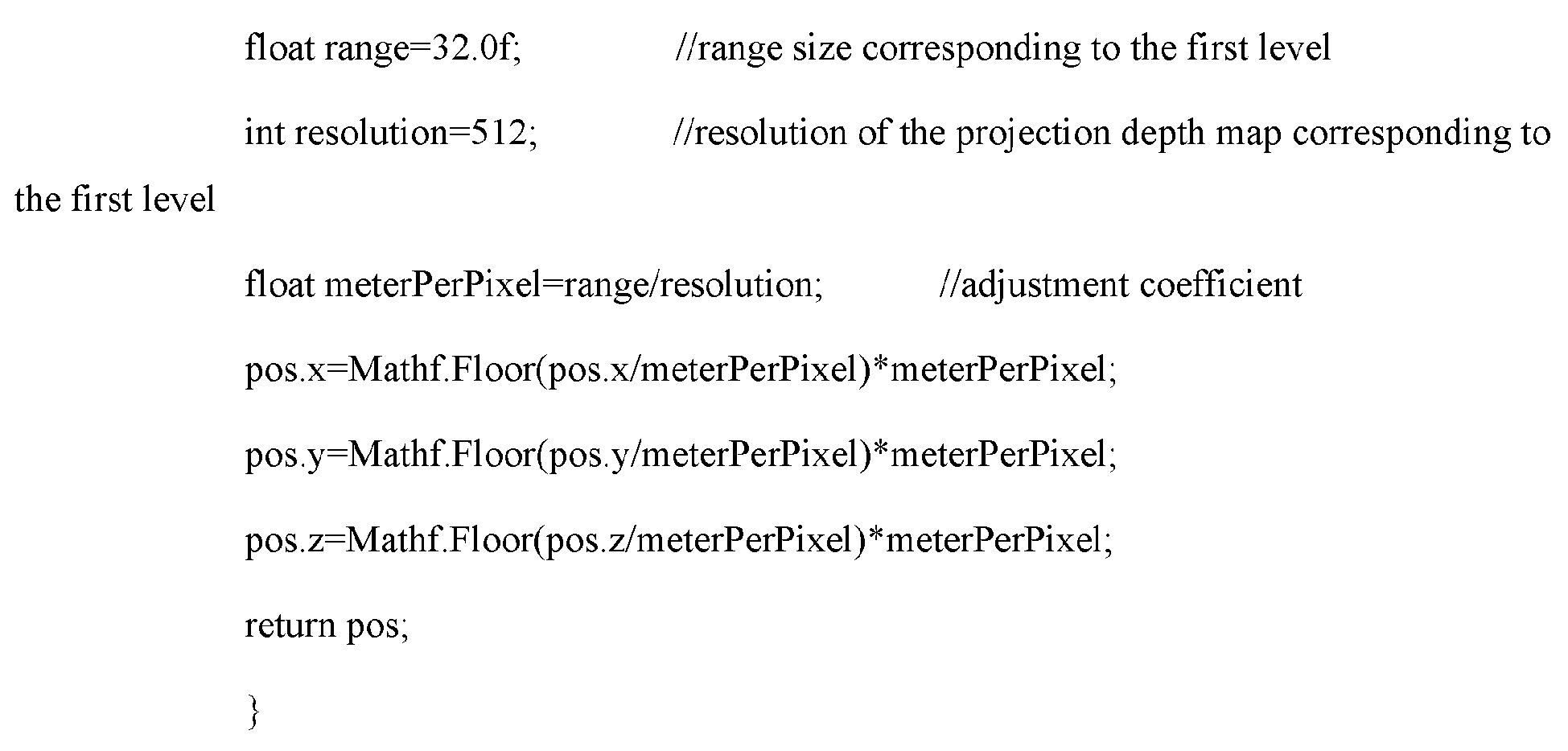
| Solution | Sight distance (meter) | Draw call | Frame rate (per second) |
| Shadow Map | 100 | 1312 | 180 |
| CSM | 200 | 2564 | 160 |
| Shadow Cache | 2000 | 1023 | 210 |
- a determining
module 1401, configured to determine scene ranges corresponding to a plurality of first levels, the scene range corresponding to the first level being a range of a first visible part included in a virtual scene or a partial range of the first visible part, - the determining
module 1401 being further configured to determine, for any one of the plurality of first levels, a first virtual item corresponding to the first level based on a scene range corresponding to the first level, the first virtual item corresponding to the first level being a virtual item whose shadow is in the scene range corresponding to the first level; and - the determining
module 1401 being further configured to determine a first projection depth map corresponding to the first level based on the first virtual item, the first projection depth map being configured for describing distances between a plurality of first vertices and a light source, the plurality of first vertices being each a vertex on a surface of the first virtual item facing the light source; and - a
rendering module 1402, configured to render the shadow in the first visible part based on the first projection depth map.
an obtaining module, configured to obtain movement information of a virtual object and scene ranges corresponding to a plurality of second levels when the virtual object moves in the virtual scene, the scene range corresponding to the second level being a range of a second visible part included in the virtual scene or a partial range in the second visible part, the first visible part being a visible scene after the virtual object moves, and the second visible part being a visible scene before the virtual object moves.
- an expansion module, configured to expand the scene range corresponding to the first level based on an expansion parameter, to obtain a reference range corresponding to the first level; and
- a selection module, configured to select a plurality of virtual items located in the reference range.
Claims (21)
- A method for shadow rendering, executable by an electronic device, and comprising:receiving a virtual scene;determining, in a first visible part in the virtual scene, a plurality of scene ranges of a plurality of first levels, each scene range being a range of the first visible part or a partial range of the first visible part corresponding to a respective one of the plurality of first levels;for the scene range of each of the plurality of first levels,determining a first virtual item corresponding to the scene range of the first level, the first virtual item being a virtual item whose shadow is within the scene range of the first level;determining a first projection depth map corresponding to the first level based on the first virtual item, the first projection depth map being configured for describing distances between a light source and a plurality of first vertices on a surface of the first virtual item facing the light source; andrendering the shadow in the first visible part based on the first projection depth map.
- The method according to claim 1, wherein the determining a plurality of scene ranges of a plurality of first levels comprises:determining the scene ranges of the plurality of first levels in response to a shadow update condition being satisfied; andthe shadow update condition is satisfied in response to at least one of the following:a virtual object moves in the virtual scene;illumination of the virtual scene changes; orthe virtual scene is initialized.
- The method according to claim 1 or 2, further comprising:obtaining movement information of a virtual object and scene ranges of a plurality of second levels when the virtual object moves in the virtual scene, the scene range of the second level being a range of a second visible part in the virtual scene or a partial range in the second visible part, the first visible part being a visible scene after the virtual object moves, and the second visible part being a visible scene before the virtual object moves;for the scene range of each of the plurality of second levels, determining a second movement amplitude of the virtual object relative to the second level based on the movement information of the virtual object and the scene range of the second level; anddetermining, in response to the plurality of second levels comprising a target level, that the shadow update condition is satisfied, a target movement amplitude of the virtual object relative to the target level being greater than a movement threshold.
- The method according to claim 1, wherein the determining a plurality of scene ranges of a plurality of first levels comprises:obtaining a range size of each of the plurality of first levels; anddetermining, for each of the plurality of first levels, a scene range of the first level in the first visible part based on a reference point of the first visible part and the range size of the first level.
- The method according to any one of claims 1 to 4, wherein the determining a first virtual item corresponding to the scene range of the first level comprises:obtaining reference projection ranges of a plurality of virtual items in the virtual scene in a first projection coordinate system;determining a first projection range of the first level in the first projection coordinate system based on the scene range corresponding to the first level; anddetermining, for any virtual item, the virtual item as the first virtual item if the reference projection range of the virtual item overlaps the first projection range.
- The method according to claim 5, wherein the method further comprises: before the obtaining reference projection ranges of a plurality of virtual items in the virtual scene in a first projection coordinate system,expanding the scene range of the first level based on an expansion parameter, to obtain a reference range of the first level; andselecting a plurality of virtual items located in the reference range.
- The method according to claim 5, wherein the obtaining reference projection ranges of a plurality of virtual items in the virtual scene in a first projection coordinate system comprises: for any virtual item,determining a bounding box of the virtual item;determining first projection information of the virtual item based on the bounding box, the first projection information being configured for describing a projection of the bounding box in the first projection coordinate system; anddetermining the reference projection range of the virtual item based on the first projection information.
- The method according to claim 7,
wherein the determining the reference projection range of the virtual item based on the first projection information comprises:determining second projection information of the virtual item based on the first projection information, the second projection information being configured for describing a bounding frame of a projection of the bounding box in the first projection coordinate system; anddetermining the second projection information as the reference projection range of the virtual item. - The method according to any one of claims 1 to 8, wherein the determining a first projection depth map corresponding to the first level based on the first virtual item comprises:determining three-dimensional projection coordinates of vertices of the first virtual item in a second projection coordinate system based on three-dimensional scene coordinates of the vertices of the first virtual item in a virtual scene coordinate system;determining an adjustment coefficient based on the scene range of the first level and a resolution of the first projection depth map;adjusting the three-dimensional projection coordinates of the vertices of the first virtual item based on the adjustment coefficient, to obtain adjusted three-dimensional projection coordinates of the vertices of the first virtual item; anddetermining the first projection depth map based on three-dimensional projection coordinates of the light source in the second projection coordinate system and the adjusted three-dimensional projection coordinates of the vertices of the first virtual item.
- The method according to claim 9,
wherein the determining the first projection depth map based on three-dimensional projection coordinates of the light source in the second projection coordinate system and the adjusted three-dimensional projection coordinates of the vertices of the first virtual item comprises:adjusting the three-dimensional projection coordinates of the light source based on the adjustment coefficient, to obtain adjusted three-dimensional projection coordinates of the light source; anddetermining the first projection depth map based on the adjusted three-dimensional projection coordinates of the light source and the adjusted three-dimensional projection coordinates of the vertices of the first virtual item. - The method according to any one of claims 1 to 8, wherein the determining a first projection depth map corresponding to the first level based on the first virtual item comprises:for any of the plurality of first levels, obtaining, in response to a related movement amplitude of a virtual object relative to a related level being greater than a movement threshold, a related projection depth map corresponding to the related level, the related level being a second level whose scene range is of a same size as a scene range of the first level, the related projection depth map being configured for describing distances between the light source and a plurality of second vertices on a surface of a third virtual item corresponding to the related level facing the light source, and the third virtual item being a virtual item whose shadow is within a scene range of the related level; anddetermining the first projection depth map based on the first virtual item and the related projection depth map.
- The method according to claim 11, wherein the determining the first projection depth map based on the first virtual item and the related projection depth map comprises:cropping the related projection depth map based on the related movement amplitude, to obtain a cropped projection depth map;determining a second virtual item corresponding to the first level from the first virtual item, the second virtual item being a virtual item whose shadow is within a remaining range of the first level, and the remaining range being a range of a remaining scene in a scene of the first level other than a partial scene corresponding to the cropped projection depth map; anddetermining the first projection depth map based on the second virtual item and the cropped projection depth map.
- The method according to claim 12, wherein the determining a second virtual item corresponding to the first level from the first virtual item comprises:determining a reference projection range of the first virtual item in the first projection coordinate system;determining a second projection range of the first level in the first projection coordinate system based on the remaining range; anddetermining the first virtual item as the second virtual item if the reference projection range of the first virtual item overlaps the second projection range.
- The method according to claim 12, wherein the determining the first projection depth map based on the second virtual item and the cropped projection depth map comprises:determining a supplementary map corresponding to the first level based on the second virtual item, the supplementary map being configured for describing distances between the light source and a plurality of third vertices on a surface of the second virtual item facing the light source; andsplicing the supplementary map and the cropped projection depth map, to obtain the first projection depth map.
- The method according to claim 11, further comprising:
determining the related projection depth map as the first projection depth map in response to the related movement amplitude being not greater than the movement threshold. - The method according to any one of claims 1 to 15,
wherein the rendering the shadow in the first visible part based on the first projection depth map comprises:determining, for any fourth vertex, a first distance between the fourth vertex and the light source, the fourth vertex being a vertex on a surface of a virtual item in the first visible part facing a camera;determining a reference level from the plurality of first levels, the fourth vertex being a vertex on a virtual item in a scene range corresponding to the reference level;determining a second distance between a first vertex corresponding to the fourth vertex and the light source from a projection depth map corresponding to the reference level; andrendering the shadow at a position of the fourth vertex in response to the first distance being greater than the second distance. - A device for shadow rendering, comprising:a determining module configured to receive a virtual scene, and determine, in a first visible part in the virtual scene, a plurality of scene ranges of a plurality of first levels, each scene range being a range of a first visible part or a partial range of the first visible part corresponding to a respective one of the plurality of first levels,wherein the determining module is further configured to, for the scene range of each of the plurality of first levels, determine a first virtual item corresponding to the scene range of the first level, the first virtual item being a virtual item whose shadow is within the scene range of the first level; and the determining module being further configured to determine a first projection depth map corresponding to the first level based on the first virtual item, the first projection depth map being configured for describing distances between a light source and a plurality of first vertices on a surface of the first virtual item facing the light source; anda rendering module, configured to render the shadow in the first visible part based on the first projection depth map.
- An electronic device, comprising a processor and a memory, the memory storing at least one computer program, and the at least one computer program being loaded and executed by the processor, to cause the electronic device to implement the shadow rendering method according to any one of claims 1 to 16.
- A non-volatile computer-readable storage medium, having at least one computer program stored therein, and the at least one computer program being loaded and executed by a processor, to cause an electronic device to implement the shadow rendering method according to any one of claims 1 to 16.
- A computer program product, having at least one computer program stored therein, and the at least one computer program being loaded and executed by a processor, to cause an electronic device to implement the shadow rendering method according to any one of claims 1 to 16.
- A computer program, there being at least one computer program, and the at least one computer program being loaded and executed by a processor, to cause an electronic device to implement the shadow rendering method according to any one of claims 1 to 16.
Applications Claiming Priority (2)
| Application Number | Priority Date | Filing Date | Title |
|---|---|---|---|
| CN202211368766.6A CN116993897A (en) | 2022-11-03 | 2022-11-03 | Shadow rendering method, device, electronic device and readable storage medium |
| PCT/CN2023/123331 WO2024093610A1 (en) | 2022-11-03 | 2023-10-08 | Shadow rendering method and apparatus, electronic device, and readable storage medium |
Publications (2)
| Publication Number | Publication Date |
|---|---|
| EP4553777A1 true EP4553777A1 (en) | 2025-05-14 |
| EP4553777A4 EP4553777A4 (en) | 2026-02-11 |
Family
ID=88527191
Family Applications (1)
| Application Number | Title | Priority Date | Filing Date |
|---|---|---|---|
| EP23884542.4A Pending EP4553777A4 (en) | 2022-11-03 | 2023-10-08 | Shadow rendering method and device, electronic device and readable storage medium |
Country Status (4)
| Country | Link |
|---|---|
| US (1) | US20250014268A1 (en) |
| EP (1) | EP4553777A4 (en) |
| CN (1) | CN116993897A (en) |
| WO (1) | WO2024093610A1 (en) |
Families Citing this family (1)
| Publication number | Priority date | Publication date | Assignee | Title |
|---|---|---|---|---|
| CN118379419B (en) * | 2024-06-24 | 2024-10-01 | 网易(杭州)网络有限公司 | Processing method and device of virtual object model, computer equipment and storage medium |
Family Cites Families (7)
| Publication number | Priority date | Publication date | Assignee | Title |
|---|---|---|---|---|
| US9773343B2 (en) * | 2010-12-24 | 2017-09-26 | Institute Of Automation, Chinese Academy Of Sciences | Method for real-time and realistic rendering of complex scenes on internet |
| WO2018175299A1 (en) * | 2017-03-24 | 2018-09-27 | Mz Ip Holdings, Llc | System and method for rendering shadows for a virtual environment |
| CN111105491B (en) * | 2019-11-25 | 2020-12-08 | 腾讯科技(深圳)有限公司 | Scene rendering method and device, computer readable storage medium and computer equipment |
| CN111489430B (en) * | 2020-04-08 | 2024-03-01 | 网易(杭州)网络有限公司 | Game light and shadow data processing method and device and game equipment |
| CN112215936B (en) * | 2020-10-16 | 2025-04-22 | 广州虎牙科技有限公司 | Image rendering method, device, electronic device and storage medium |
| US11232628B1 (en) * | 2020-11-10 | 2022-01-25 | Weta Digital Limited | Method for processing image data to provide for soft shadow effects using shadow depth information |
| CN113256781B (en) * | 2021-06-17 | 2023-05-30 | 腾讯科技(深圳)有限公司 | Virtual scene rendering device, storage medium and electronic equipment |
-
2022
- 2022-11-03 CN CN202211368766.6A patent/CN116993897A/en active Pending
-
2023
- 2023-10-08 WO PCT/CN2023/123331 patent/WO2024093610A1/en not_active Ceased
- 2023-10-08 EP EP23884542.4A patent/EP4553777A4/en active Pending
-
2024
- 2024-09-13 US US18/885,221 patent/US20250014268A1/en active Pending
Also Published As
| Publication number | Publication date |
|---|---|
| US20250014268A1 (en) | 2025-01-09 |
| WO2024093610A1 (en) | 2024-05-10 |
| CN116993897A (en) | 2023-11-03 |
| EP4553777A4 (en) | 2026-02-11 |
Similar Documents
| Publication | Publication Date | Title |
|---|---|---|
| US12347016B2 (en) | Image rendering method and apparatus, device, medium, and computer program product | |
| US11748840B2 (en) | Method for efficient re-rendering objects to vary viewports and under varying rendering and rasterization parameters | |
| US20220249949A1 (en) | Method and apparatus for displaying virtual scene, device, and storage medium | |
| CN112370784B (en) | Virtual scene display method, device, equipment and storage medium | |
| KR101086570B1 (en) | Dynamic window structure | |
| WO2024027237A1 (en) | Rendering optimization method, and electronic device and computer-readable storage medium | |
| US20250371799A1 (en) | Illumination Rendering Methods and Systems | |
| KR20180107271A (en) | Method and apparatus for generating omni media texture mapping metadata | |
| WO2021253640A1 (en) | Shadow data determination method and apparatus, device, and readable medium | |
| US20250342646A1 (en) | Image Display Method for Virtual Scene, Device, Medium, and Program Product | |
| WO2017174006A1 (en) | Image processing method and device | |
| US20250014268A1 (en) | Shadow rendering method and apparatus, electronic device, and readable storage medium | |
| CN110930497B (en) | Global illumination intersection acceleration method and device and computer storage medium | |
| US20250166281A1 (en) | Rendering Method and Apparatus, Device, and Storage Medium | |
| CN115526977B (en) | Game picture rendering method and device | |
| CN106683155A (en) | Three-dimensional model comprehensive dynamic scheduling method | |
| US20250336139A1 (en) | Model seam repairing | |
| CN120129927A (en) | Method and system for rendering video graphics using scene segmentation | |
| WO2019231668A1 (en) | Casting shadows using silhouettes | |
| CN116777731A (en) | Method, apparatus, device, medium and program product for soft rasterization | |
| CN117959704A (en) | Virtual model placement method and device, electronic equipment and readable storage medium | |
| CN116824082A (en) | Virtual terrain rendering methods, devices, equipment, storage media and program products | |
| CN115970281A (en) | Model icon generation method, device, equipment and storage medium | |
| HK40100926A (en) | Shadow rendering method, device, electronic equipment and readable storage medium | |
| CN115430144B (en) | Ambient light shielding implementation method and device, computer storage medium, and electronic device |
Legal Events
| Date | Code | Title | Description |
|---|---|---|---|
| STAA | Information on the status of an ep patent application or granted ep patent |
Free format text: STATUS: THE INTERNATIONAL PUBLICATION HAS BEEN MADE |
|
| PUAI | Public reference made under article 153(3) epc to a published international application that has entered the european phase |
Free format text: ORIGINAL CODE: 0009012 |
|
| STAA | Information on the status of an ep patent application or granted ep patent |
Free format text: STATUS: REQUEST FOR EXAMINATION WAS MADE |
|
| 17P | Request for examination filed |
Effective date: 20250207 |
|
| AK | Designated contracting states |
Kind code of ref document: A1 Designated state(s): AL AT BE BG CH CY CZ DE DK EE ES FI FR GB GR HR HU IE IS IT LI LT LU LV MC ME MK MT NL NO PL PT RO RS SE SI SK SM TR |
|
| RIC1 | Information provided on ipc code assigned before grant |
Ipc: G06T 15/60 20060101AFI20251009BHEP |
|
| A4 | Supplementary search report drawn up and despatched |
Effective date: 20260112 |
|
| DAV | Request for validation of the european patent (deleted) | ||
| DAX | Request for extension of the european patent (deleted) | ||
| RIC1 | Information provided on ipc code assigned before grant |
Ipc: G06T 15/60 20060101AFI20260105BHEP |