EP4553748A1 - Carbon management system and computation processing device - Google Patents
Carbon management system and computation processing device Download PDFInfo
- Publication number
- EP4553748A1 EP4553748A1 EP22950230.7A EP22950230A EP4553748A1 EP 4553748 A1 EP4553748 A1 EP 4553748A1 EP 22950230 A EP22950230 A EP 22950230A EP 4553748 A1 EP4553748 A1 EP 4553748A1
- Authority
- EP
- European Patent Office
- Prior art keywords
- facility
- carbon
- exhaust gas
- amount
- recovery
- Prior art date
- Legal status (The legal status is an assumption and is not a legal conclusion. Google has not performed a legal analysis and makes no representation as to the accuracy of the status listed.)
- Pending
Links
Images








Classifications
-
- G—PHYSICS
- G06—COMPUTING OR CALCULATING; COUNTING
- G06Q—INFORMATION AND COMMUNICATION TECHNOLOGY [ICT] SPECIALLY ADAPTED FOR ADMINISTRATIVE, COMMERCIAL, FINANCIAL, MANAGERIAL OR SUPERVISORY PURPOSES; SYSTEMS OR METHODS SPECIALLY ADAPTED FOR ADMINISTRATIVE, COMMERCIAL, FINANCIAL, MANAGERIAL OR SUPERVISORY PURPOSES, NOT OTHERWISE PROVIDED FOR
- G06Q50/00—Information and communication technology [ICT] specially adapted for implementation of business processes of specific business sectors, e.g. utilities or tourism
- G06Q50/04—Manufacturing
-
- B—PERFORMING OPERATIONS; TRANSPORTING
- B01—PHYSICAL OR CHEMICAL PROCESSES OR APPARATUS IN GENERAL
- B01D—SEPARATION
- B01D53/00—Separation of gases or vapours; Recovering vapours of volatile solvents from gases; Chemical or biological purification of waste gases, e.g. engine exhaust gases, smoke, fumes, flue gases, aerosols
- B01D53/34—Chemical or biological purification of waste gases
- B01D53/346—Controlling the process
-
- B—PERFORMING OPERATIONS; TRANSPORTING
- B01—PHYSICAL OR CHEMICAL PROCESSES OR APPARATUS IN GENERAL
- B01D—SEPARATION
- B01D53/00—Separation of gases or vapours; Recovering vapours of volatile solvents from gases; Chemical or biological purification of waste gases, e.g. engine exhaust gases, smoke, fumes, flue gases, aerosols
- B01D53/34—Chemical or biological purification of waste gases
- B01D53/46—Removing components of defined structure
- B01D53/62—Carbon oxides
-
- G—PHYSICS
- G06—COMPUTING OR CALCULATING; COUNTING
- G06Q—INFORMATION AND COMMUNICATION TECHNOLOGY [ICT] SPECIALLY ADAPTED FOR ADMINISTRATIVE, COMMERCIAL, FINANCIAL, MANAGERIAL OR SUPERVISORY PURPOSES; SYSTEMS OR METHODS SPECIALLY ADAPTED FOR ADMINISTRATIVE, COMMERCIAL, FINANCIAL, MANAGERIAL OR SUPERVISORY PURPOSES, NOT OTHERWISE PROVIDED FOR
- G06Q10/00—Administration; Management
- G06Q10/06—Resources, workflows, human or project management; Enterprise or organisation planning; Enterprise or organisation modelling
- G06Q10/063—Operations research, analysis or management
-
- G—PHYSICS
- G06—COMPUTING OR CALCULATING; COUNTING
- G06Q—INFORMATION AND COMMUNICATION TECHNOLOGY [ICT] SPECIALLY ADAPTED FOR ADMINISTRATIVE, COMMERCIAL, FINANCIAL, MANAGERIAL OR SUPERVISORY PURPOSES; SYSTEMS OR METHODS SPECIALLY ADAPTED FOR ADMINISTRATIVE, COMMERCIAL, FINANCIAL, MANAGERIAL OR SUPERVISORY PURPOSES, NOT OTHERWISE PROVIDED FOR
- G06Q10/00—Administration; Management
- G06Q10/30—Administration of product recycling or disposal
-
- G—PHYSICS
- G06—COMPUTING OR CALCULATING; COUNTING
- G06Q—INFORMATION AND COMMUNICATION TECHNOLOGY [ICT] SPECIALLY ADAPTED FOR ADMINISTRATIVE, COMMERCIAL, FINANCIAL, MANAGERIAL OR SUPERVISORY PURPOSES; SYSTEMS OR METHODS SPECIALLY ADAPTED FOR ADMINISTRATIVE, COMMERCIAL, FINANCIAL, MANAGERIAL OR SUPERVISORY PURPOSES, NOT OTHERWISE PROVIDED FOR
- G06Q50/00—Information and communication technology [ICT] specially adapted for implementation of business processes of specific business sectors, e.g. utilities or tourism
- G06Q50/06—Energy or water supply
-
- B—PERFORMING OPERATIONS; TRANSPORTING
- B01—PHYSICAL OR CHEMICAL PROCESSES OR APPARATUS IN GENERAL
- B01D—SEPARATION
- B01D2257/00—Components to be removed
- B01D2257/50—Carbon oxides
- B01D2257/504—Carbon dioxide
-
- B—PERFORMING OPERATIONS; TRANSPORTING
- B01—PHYSICAL OR CHEMICAL PROCESSES OR APPARATUS IN GENERAL
- B01D—SEPARATION
- B01D2258/00—Sources of waste gases
- B01D2258/02—Other waste gases
- B01D2258/0283—Flue gases
Definitions
- the present invention relates to a carbon management system and a computation processing device.
- Patent Literatures 1 and 2 are known regarding recovery of CO 2 discharged from factories and the like.
- Patent Literature 1 discloses a system that converts discharge of CO 2 to costs, evaluates the costs of the process path, and proposes an optimum path.
- Patent Literature 2 discloses an information management system for managing identification information of a user of a CO 2 recovery apparatus and information on the CO 2 recovery amount, the use application, and use amount among a CO 2 collection station, a transport vehicle, a processing factory for converting CO 2 into fuel, and an information management center.
- Patent Literatures 1 and 2 do not disclose an operation of a CO 2 recovery facility or a CO 2 recycling facility considering a supply/demand balance of CO 2 or a carbon-containing substance including CO 2 .
- a system which adjusts a supply/demand balance of CO 2 or a recycled carbon-containing substance has been demanded in order to operate a CO 2 recovery facility, a CO 2 recycling facility, and the like, which are major constituent elements.
- an object of the present invention is to provide a carbon management system and the like which are capable of adjusting a supply/demand balance of CO 2 or a carbon-containing substance.
- a carbon management system comprises: a plurality of discharge sources which discharge an exhaust gas containing CO 2 ; a CO 2 recovery facility which separates and recovers CO 2 from the exhaust gas discharged from the plurality of discharge sources; a conduit which is provided between the plurality of discharge sources and the CO 2 recovery facility such that the exhaust gas discharged from the discharge sources is collected in the CO 2 recovery facility; and a computation processing device which sets an operating condition of at least one of the plurality of discharge sources or an operating condition of the CO 2 recovery facility.
- the present invention makes it possible to provide a carbon management system and the like which are capable of adjusting a supply/demand balance of CO 2 or a carbon-containing substance.
- a carbon management system 100 (see FIG. 1 ) according to one embodiment of the present invention is configured to collect a plurality of exhaust gases containing CO 2 in areas such as an industrial park where the exhaust gases containing CO 2 are discharged, collectively recover CO 2 , and supply CO 2 to facilities downstream of the carbon management system 100. This makes it possible to disperse the burden of costs associated with the introduction of CO 2 reduction technologies, and further to reduce the load of each element facility and manage supplies and demands.
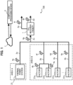
- FIG. 1 is a configuration diagram of the carbon management system 100 according to a first embodiment.
- the carbon management system 100 includes: a plurality of discharge sources (a thermal power station 21 and factories 31a to 31n in the example of FIG. 1 ) which discharge exhaust gases containing CO 2 (carbon dioxide); a CO 2 recovery facility 1 which collects the exhaust gases discharged from the plurality of discharge sources and separates and recovers CO 2 from the collected exhaust gases; conduits 2a to 2c which guide the exhaust gases discharged from the plurality of discharge sources to the CO 2 recovery facility 1; and a computation processing device 3 which sets an operating plan (operating condition) of at least one of the plurality of discharge sources or an operating plan (operating condition) of the CO 2 recovery facility 1.
- a plurality of discharge sources a thermal power station 21 and factories 31a to 31n in the example of FIG. 1
- CO 2 recovery facility 1 which collects the exhaust gases discharged from the plurality of discharge sources and separates and recovers CO 2 from the collected exhaust gases
- conduits 2a to 2c which
- the plurality of discharge sources includes, for example, a discharge source which discharges a large amount and a high concentration of CO 2 and a discharge source which discharges a smaller amount or a lower concentration of CO 2 than the former discharge source.
- a thermal power station 21 is provided in the example of FIG. 1 .
- the thermal power station 21 includes, for example, a gas thermal power station, a coal thermal power station, a steel plant, and the like.
- the conduits 2a to 2c are provided between the discharge sources and the CO 2 recovery facility 1, and are configured such that the exhaust gases discharged from the plurality of discharge sources are collected in the CO 2 recovery facility 1.
- the area B includes, for example, an industrial district, an industrial park, and the like.
- factories 31a to 31n include, for example, the chemical product production industry, the food processing industry, the iron steel industry, the cement industry, and the like.
- the conduits 2b are connected, respectively. Then, the exhaust gas discharged from each of the factories 31a to 31n and the exhaust gas discharged from the thermal power station 21 flow through the conduit 2b and the conduit 2a, respectively, join together in the conduit 2c, and the exhaust gases thus joined are guided to the CO 2 recovery facility 1 by the conduit 2c. That is, the exhaust gases discharged from the area A and the area B are supplied to the CO 2 recovery facility 1 through the conduits 2a and 2b.
- the CO 2 recovery facility 1 has a function of recovering CO 2 in an exhaust gas.
- the method for recovering CO 2 includes, for example, a chemical absorption method which brings an alkaline CO 2 absorption liquid and an exhaust gas into contact to cause the CO 2 absorption liquid to absorb CO 2 in the exhaust gas.
- a physical adsorption method which uses an adsorption agent utilizing a Van der Waals' force
- a chemical adsorption method which brings an alkaline CO 2 adsorption material (solid) and an exhaust gas into contact to cause the CO 2 adsorption material to adsorb CO 2 in the exhaust gas, and the like.
- the CO 2 recovery facility 1 may be installed in a site different from the site of a discharge source, or may be installed in the same site (in the factory) as that of a discharge source. That is, the CO 2 recovery facility 1 may be provided in a site in which any of the plurality of discharge sources is disposed.
- FIG. 1 has a configuration in which the conduit 2a through which the exhaust gas discharged from the area A flows and the conduits 2b through which the exhaust gas discharged from the area B flows are connected to the conduit 2c to be joined, and thereafter the exhaust gases are supplied to the CO 2 recovery facility 1, the configuration is not limited to this.
- the exhaust gas from the area A and the exhaust gas from the area B may be each individually supplied to the CO 2 recovery facility 1.
- the exhaust gases of the conduit 2a of the area A and the conduits 2b of the area B be brought together (joined) at the conduit 2c before the CO 2 recovery facility 1, and thereafter be supplied to the CO 2 recovery facility 1, because CO 2 to be supplied to the CO 2 recovery facility 1 can be collectively managed.
- carbon detecting units 4a to 4i which are capable of measuring the concentration in terms of carbon of carbon-containing components in an exhaust gas and the flow rate of the exhaust gas are included.
- the carbon detecting units 4a to 4e are installed near outlets of exhaust gas generation sources (the thermal power station 21 and the factories 31a to 31n), respectively.
- the carbon detecting unit 4f is installed at a point at which outlet conduits of the factories 31a and 31b, which are exhaust gas generation sources of the area B, join.
- the carbon detecting unit 4g is installed near an inlet of the CO 2 recovery facility 1 (a portion through which the exhaust gases having joined flow).
- a "first detecting unit” which acquires a concentration in terms of carbon (hereinafter, referred to as a carbon concentration) of a carbon-containing component in an exhaust gas discharged from the discharge sources and a flow rate of the exhaust gas is configured to include the carbon detecting units 4a to 4g.
- the carbon detecting unit 4h shown in FIG. 1 is installed on the conduit 2d for CO 2 which flows out of the CO 2 recovery facility 1.
- the carbon detecting unit 4i is installed on the conduit 2e (outlet gas conduit) through which a gas other than CO 2 flows out of the CO 2 recovery facility 1.
- a "second detecting unit" which acquires a concentration in terms of carbon of a carbon-containing component in a gas discharged from the CO 2 recovery facility 1 and a flow rate of the gas is configured to include the carbon detecting units 4h and 4i.
- the carbon-containing components in the exhaust gas include CO 2 , CO, CH 4 , and the like.
- the method for measuring a carbon-containing component in an exhaust gas can be achieved by utilizing, for example, a mass analysis, a gas chromatography analysis, an infrared spectroscopy, a cavity-ring-down spectroscopy, or the like.
- the flow rate of the exhaust gas can be detected by using a process gas flowmeter, or the like.
- the concentration and the flow rate of these carbon components (CO 2 , CO, CH 4 ) may be calculated based on a fuel use amount of the exhaust gas generation source.
- Information of the carbon detecting units 4a to 4i is collected in a data collecting system 7 (database) through a network (not shown).
- the computation processing device 3 of the carbon management system 100 is capable of communicating with the data collecting system 7 through the network (not shown).
- the computation processing device 3 sets operating plans of the CO 2 recovery facility 1 and each discharge source by using the information of the carbon detecting units 4a to 4i collected in the data collecting system 7. That is, the computation processing device 3 has a computation processing function of setting an operating condition of at least one of the plurality of discharge sources or the CO 2 recovery facility 1, and a management function of managing at least one of the plurality of discharge sources and the CO 2 recovery facility 1, based on data acquired by the carbon detecting units 4a to 4g (the first detecting unit) and the carbon detecting units 4h and 4i (the second detecting unit).
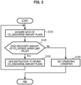
- FIG. 2 is a flowchart showing processing in the carbon management system (see also FIG. 1 as appropriate).
- the computation processing device 3 sets a value obtained by adding up the CO 2 discharge amount plans on a daily basis of all the exhaust gas generation sources as a planned initial value of the CO 2 recovery amount in the CO 2 recovery facility 1 in the computation processing function of setting an operating condition (operating plan) of the CO 2 recovery facility 1.
- Step S102 The computation processing device 3 determines whether or not the recovery amount (for example, a recovery amount per day) of CO 2 in the CO 2 recovery facility 1 exceeds a predetermined upper limit value. If the recovery amount of CO 2 does not exceed the upper limit value in step S102 (S102: No), the processing of the computation processing device 3 returns to "START". In addition, if the recovery amount of CO 2 exceeds the upper limit value in step S102 (S102: Yes), the processing of the computation processing device 3 proceeds to step S103.
- the recovery amount for example, a recovery amount per day
- Step S103 The computation processing device 3 gives an instruction to review the CO 2 discharge amount plans. For example, in the case where there is a period of time (time t1 to t2 in FIG. 3A ) during which this planned initial value exceeds a designed upper limit value for a CO 2 amount which can be recovered in the CO 2 recovery facility 1, the computation processing device 3 instructs the exhaust gas generation sources to review the CO 2 discharge amount plans of the period of time (time t1 to t2) during which the CO 2 amount exceeds the upper limit value, in the management function for the discharge sources and the CO 2 recovery facility 1. That is, the computation processing device 3 transmits a predetermined instruction signal regarding the review of the CO 2 discharge amount plans to the thermal power station 21 and the factories 31a to 31n.
- the thermal power station 21 and the factories 31a to 31n in each area reset the CO 2 discharge amount plans based on the instruction (S103) from the computation processing device 3, and transmit data of the CO 2 discharge amount plans after the resetting to the computation processing device 3.
- the computation processing device 3 acquires data of the CO 2 discharge amount plans again (S101). In this way, the CO 2 discharge amount plans after the resetting are reregistered in the computation processing device 3.
- the computation processing device 3 adds up the CO 2 discharge amount plans on a daily basis of all the exhaust gas generation sources again, in the computation processing function of setting the operating condition. If the computation processing device 3 determines that the CO 2 recovery amount of the CO 2 recovery facility does not exceed the designed upper limit (upper limit value) during the predetermined period of time in the management function for the discharge sources and the CO 2 recovery facility 1 (S103: No), the computation processing device 3 determines that an operating preparation of the CO 2 recovery facility 1 is completed, and proceeds to the processing of step S104.
- the designed upper limit upper limit value
- Step S104 The computation processing device 3 sets an operating condition of the CO 2 recovery facility 1 (computation processing).
- the computation processing device 3 measures discharged CO 2 amounts of the carbon detecting units 4a to 4e included on the conduits 2a and 2b of the exhaust gas generation sources in the management function for the discharge sources and the CO 2 recovery facility 1, and calculates a difference from a reset planned value for each of the carbon detecting units 4a to 4e. If the computation processing device 3 determines that a detected value of the CO 2 discharge amount exceeds the replanned value, although omitted in FIG. 2 , the computation processing device 3 specifies a carbon detecting unit which has caused the detected value to exceed the planned value, and notifies an exhaust gas generation source associated with the specified carbon detecting unit to further reduce the discharged CO 2 amount and of the reduction amount.
- the computation processing device 3 manages the replanned value and the detected value of the CO 2 recovery amount in the CO 2 recovery facility 1.
- the computation processing device 3 specifies a carbon detecting unit which has caused the detected value to be about to exceed the planned value. Then, the computation processing device 3 notifies an exhaust gas generation source (the thermal power station 21 or the factory 31a to 31n) associated with the specified carbon detecting unit to further reduce the discharged CO 2 amount and of the reduction amount.
- the detected value of the CO 2 recovery amount in the computation processing function of setting the operating condition of the CO 2 recovery facility 1 is calculated from measured values of the CO 2 concentration in the exhaust gases in the carbon detecting units 4g and 4h shown in FIG. 1 and the amounts of the exhaust gases.
- the exhaust gas generation source which has been notified to reduce the CO 2 discharge amount and the reduction amount reduces the CO 2 discharge amount.
- the computation processing device 3 checks whether or not this exhaust gas generation source has reduced the CO 2 discharge amount from information of the carbon detecting unit. In this way, the computation processing device 3 calculates the CO 2 supply amount to be supplied from the plurality of discharge sources to the CO 2 recovery facility 1 and calculates a reduction amount of the CO 2 discharge amount to be discharged from the discharge sources such that the CO 2 supply amount to be supplied to the CO 2 recovery facility 1 falls within a designed value of the CO 2 recovery facility 1, based on the carbon concentrations and the flow rates of the exhaust gases acquired by the carbon detecting units 4a to 4g (first detecting unit).
- FIG. 3A is an explanatory diagram of a CO 2 discharge amount plan in the case where the CO 2 recovery amount in a CO 2 recovery facility is predicted to temporarily exceed the upper limit.
- five graphs in total included in FIG. 3A indicate the transition of the CO 2 discharge amount in the thermal power station 21 in the area A, transitions of the CO 2 discharge amounts in the factories 31a, 31b, and 31n, and the transition of a predicted value of the CO 2 recovery amount in the CO 2 recovery facility 1, in this order from the top.
- the sum of the CO 2 discharge amounts of the thermal power station 21 and the factories 31a, 31b, and 31n at each time is the CO 2 recovery amount of the CO 2 recovery facility 1.
- it is predicted that the CO 2 recovery amount will exceed a predetermined upper limit value Q0 in a time zone of time t1 to t2 in the CO 2 recovery facility 1.
- FIG. 3B is an explanatory diagram of the CO 2 discharge amount plan after the CO 2 discharge amount plan has been reviewed.
- the CO 2 discharge amount plans are reviewed in the factories 31a and 31b, so that the CO 2 discharge amount in the time zone including time t1 to t2 is reduced, based on the instruction (S103 in FIG. 2 ) from the computation processing device 3. This makes the CO 2 recovery amount (replanned value) in the CO 2 recovery facility 1 equal to or lower than the predetermined upper limit value Q0.
- FIG. 3C is an explanatory diagram regarding actual CO 2 discharge amounts.
- the computation processing device 3 If the computation processing device 3 has determined that the detected value of the CO 2 discharge amount exceeded the replanned value in each discharge source, the computation processing device 3 notifies the discharge source to further reduce the CO 2 discharge amount and of the reduction amount as described above.
- the carbon management system 100 includes the computation processing device 3 which communicates with the CO 2 recovery facility 1 which collects exhaust gases discharged from the plurality of discharge sources through the conduits 2a to 2g and separates CO 2 from the collected exhaust gases.
- the computation processing device 3 sets an operating condition of at least one of the plurality of discharge sources or an operating condition of the CO 2 recovery facility.
- the computation processing device 3 can determine whether or not the CO 2 discharge amount from each discharge source should be adjusted based on the designed upper limit value of the CO 2 recovery facility 1 and the CO 2 discharge plans of the discharge sources and instruct the discharge source to reduce the CO 2 discharge amount.
- the burden of costs would increase.
- the first embodiment since exhaust gases are collected in an industrial park or the like and collectively recovered, it becomes possible to disperse the burden of costs associated with the introduction of CO 2 reduction technologies. Then, by making the CO 2 supply amounts of the CO 2 recovery facility 1, the recycling facility, and the like fall within a design range, and adjusting the supply and demand, it is possible to reduce the operating load and secure the purity of products and the supply/demand balance. In this way, the first embodiment makes it possible to provide a carbon management system 100 which can adjust the supply/demand balance of CO 2 or a carbon-containing substance.
- the "carbon-containing substance" includes CO 2 as well.
- a second embodiment is different from the first embodiment in that an exhaust gas accumulating facility (see FIG. 4 ) is provided between a plurality of discharge sources and a CO 2 recovery facility 1 (see FIG. 4 ).
- the second embodiment is different from the first embodiment in that a DAC facility 6 (see FIG. 4 ) is provided. Note that the other configurations are the same as in the first embodiment. Hence, portions different from the first embodiment will be described, and repetitive descriptions of the same portions will be omitted.
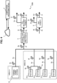
- FIG. 4 is a configuration diagram of a carbon management system 100A according to the second embodiment.
- a method for controlling a CO 2 supply amount such that the CO 2 recovery amount of the CO 2 recovery facility 1 can be made equal to or lower than the upper limit value without particularly changing the CO 2 discharge amount plans of exhaust gas generation sources in the case where each exhaust gas generation source as described in the first embodiment cannot flexibly change the CO 2 discharge amount plan will be described.
- the carbon management system 100A shown in FIG. 4 includes an exhaust gas accumulating facility 5 (exhaust gas storing unit) provided between discharge sources which discharge CO 2 and the CO 2 recovery facility 1 and further includes a DAC(Direct Air Capture) facility 6 provided at any desired location in addition to the same configurations as those of the first embodiment. Note that forms of connections of conduits connecting each facility such as the discharge sources, the CO 2 recovery facility 1, and the carbon detecting units 4a to 4i are the same as in the first embodiment.
- the exhaust gas accumulating facility 5 has a function of accumulating exhaust gases from discharge sources such as the thermal power station 21 and the factories 31a to 31n.
- a predetermined upper limit value is set for an exhaust gas accumulated amount in the exhaust gas accumulating facility 5, and the exhaust gas accumulated amount is managed so as not to exceed the upper limit value.
- the amount of exhaust gas present in the exhaust gas accumulating facility 5 is calculated from the pressure inside the exhaust gas accumulating facility 5 and relations between the supply amount and the release amount of the exhaust gas in the exhaust gas accumulating facility 5.
- the exhaust gas accumulating facility 5 is connected to a conduit 2f at which exhaust gases from the respective discharge sources of CO 2 join.
- the exhaust gas accumulated in the exhaust gas accumulating facility 5 is guided to the CO 2 recovery facility 1 through a conduit 2g.
- the exhaust gas accumulating facility may be individually installed downstream of each discharge source, and the installation locations and the number of exhaust gas accumulating facilities installed are not limited.
- the conduit itself which connects the discharge sources and the CO 2 recovery facility 1 may be regarded as the exhaust gas accumulating facility, and the form of installation is not particularly limited.
- the DAC facility 6 has a function of recovering CO 2 in the atmosphere.
- the recovery method of the DAC facility 6 may be the same as that of the CO 2 recovery facility 1. That is, the method for recovering the CO 2 includes a chemical absorption method which brings an alkaline CO 2 absorption liquid and an exhaust gas into contact to cause the CO 2 absorption liquid to absorb CO 2 in the exhaust gas, a physical adsorption method which uses an adsorption agent utilizing a Van der Waals' force, a chemical adsorption method which brings an alkaline CO 2 adsorption material (solid) and an exhaust gas into contact to cause the CO 2 adsorption material to adsorb CO 2 in the exhaust gas, and the like.
- a conduit 2h on the inlet side of the DAC facility 6 may be connected to, for example, any of the conduits 2a to 2g or may be connected to another predetermined portion.
- the carbon management system 100A further includes carbon detecting units 4j to 4n which are capable of measuring the concentration in terms of carbon of carbon-containing components in an exhaust gas and the flow rate of the exhaust gas in addition to the carbon detecting units 4a to 4i described in the first embodiment.
- the carbon detecting unit 4j is installed on the conduit 2g on the outlet side of the exhaust gas accumulating facility 5.
- the carbon detecting unit 4k is installed on the conduit 2h on the inlet side of the DAC facility 6.
- the carbon detecting unit 4m is installed on a conduit 2i which guides recovered CO 2 flowing out of the DAC facility 6.
- the carbon detecting unit 4n is installed on a conduit 2k (outlet gas conduit) which guides a gas other than the recovered CO 2 flowing out of the DAC facility 6.
- Data detected by these carbon detecting units 4a to 4n is collected to the data collecting system 7 which is connected to the computation processing device 3 like the first embodiment.
- FIG. 5 is a flowchart showing processing in the carbon management system (see also FIG. 4 as appropriate).
- steps S201, S202, and S204 of FIG. 5 are the same as steps S101, S102, and S104 of the first embodiment (see FIG. 2 ) in this order.
- the computation processing device 3 sets a value obtained by adding up the CO 2 discharge amount plans on a daily basis of all the exhaust gas generation sources as a planned initial value of the CO 2 recovery amount in the CO 2 recovery facility 1 in the computation processing function of setting operating conditions (operating plans) of the exhaust gas accumulating facility 5 and the like.
- Step S202 The computation processing device 3 determines whether or not the recovery amount (for example , a recovery amount per day) of CO 2 in the CO 2 recovery facility 1 exceeds a predetermined upper limit value. If the recovery amount of CO 2 does not exceed the upper limit value in step S202 (S202: No), the processing of the computation processing device 3 returns to "START". In addition, if the recovery amount of CO 2 exceeds the upper limit value in step S202 (S202: Yes), the processing of the computation processing device 3 proceeds to step S203.
- the recovery amount for example , a recovery amount per day
- the computation processing device 3 acquires actual values of CO 2 discharge amounts of the discharge sources of each area from the carbon detecting units 4a to 4n, and supplies the exhaust gas to the exhaust gas accumulating facility 5 in accordance with the operating condition of the exhaust gas accumulating facility 5.
- the computation processing device 3 changes the operating plan of the exhaust gas accumulating facility 5 as appropriate depending on the increase or decrease. Note that in a time zone (t ⁇ t1, t>t2 in FIG.
- the exhaust gas accumulated in the exhaust gas accumulating facility 5 may be supplied to an extent that does not exceed the designed upper limit value of the CO 2 recovery facility 1.
- the computation processing device 3 instructs the DAC facility 6 to recover CO 2 in an amount corresponding to the excess from the designed upper limit value in a time zone during which the amount exceeds the upper limit value.
- the DAC facility 6 recovers CO 2 in accordance with the plan, if the amount of exhaust gases from the discharge sources is larger than the plan, the operating condition of the DAC facility 6 is changed as appropriate. Note that regarding this time zone (t1 to t2 in FIG. 6A ), the exhaust gas in an amount equal to or more than the designed value may be released to the atmosphere without being supplied to the CO 2 recovery facility 1, for example.
- the operating time of the DAC facility 6 is preferably set out of the time zone (t1 to t2) of FIG. 6A described next.
- FIG. 6A is an explanatory diagram of a CO 2 discharge amount plan in the case where the CO 2 recovery amount in a CO 2 recovery facility is predicted to temporarily exceed the upper limit. Note that FIG. 6A is similar to FIG. 3A used in the description of the first embodiment, and it is predicted that the CO 2 recovery amount will exceed the predetermined upper limit value Q0 in a time zone of time t1 to t2 in the CO 2 recovery facility 1. In such a case, the computation processing device 3 transmits a predetermined instruction signal to the exhaust gas accumulating facility 5 such that the CO 2 recovery amount at each time is made to be equal to or lower than the upper limit value Q0.
- FIG. 6B is an explanatory diagram after the CO 2 accumulated amount has been reviewed.
- the CO 2 recovery amount in the CO 2 recovery facility 1 is made to be equal to or lower than the upper limit value Q0 and transitions near the upper limit value Q0 by adjusting the CO 2 accumulated amount at each time in the exhaust gas accumulating facility 5.
- the thermal power station 21 in the area A and the factories 31a to 31n in the area B can be operated without particularly changing the initial CO 2 discharge amount plans (see FIG. 6A ).
- FIG. 6C is an explanatory diagram showing another example after the CO 2 accumulated amount has been reviewed.
- the detected value of the CO 2 accumulated amount in the computation processing function of setting the operating condition of the exhaust gas accumulating facility 5 is calculated from measured values of the CO 2 concentrations in the gases and the gas amounts of the carbon detecting units 4g and 4j of FIG. 4 .
- the CO 2 accumulated amount of the exhaust gas accumulating facility 5 can be calculated by a method that does not use a carbon detecting unit, for example, based on a detected value of a manometer (not shown) provided in the exhaust gas accumulating facility 5.
- the computation processing device 3 calculates a CO 2 supply amount from the plurality of discharge sources to the CO 2 recovery facility 1 based on the carbon concentrations and the flow rates of the exhaust gases acquired by the carbon detecting units 4a to 4g (first detecting unit). Then, in the case where the CO 2 recovery amount exceeds the designed value (upper limit value) of the CO 2 recovery facility 1, the computation processing device 3 causes the exhaust gas accumulating facility 5 (exhaust gas storing unit) to temporarily store the exhaust gas in an amount corresponding to this excess of the designed value.
- the computation processing device 3 sets the operating condition of the exhaust gas accumulating facility 5 such that the exhaust gas is supplied from the exhaust gas accumulating facility 5 to the CO 2 recovery facility 1 to an extent that the amount does not exceed the designed value of the CO 2 recovery facility 1.
- the detected value of the CO 2 recovery amount in the computation processing function of setting the operating condition of the DAC facility 6 is calculated from the measured values of the CO 2 concentrations in the gases and the gas amounts of the carbon detecting units 4k, 4m, and 4n of FIG. 4 .
- the computation processing device 3 calculates the CO 2 supply amount from the plurality of discharge sources to the CO 2 recovery facility 1 based on the carbon concentrations and the flow rates of the exhaust gases acquired by the carbon detecting units 4a to 4g (first detecting unit). Then, in the case where the CO 2 supply amount exceeds the designed value (the upper limit value) of the CO 2 recovery facility 1, the computation processing device 3 supplies the exhaust gas only in an amount equal to the designed value of the CO 2 recovery facility 1 from the plurality of discharge sources to the CO 2 recovery facility 1.
- the computation processing device 3 calculates an excess CO 2 amount by which the CO 2 supply amount exceeds the designed value of the CO 2 recovery facility 1 from the CO 2 supply amount and the designed value, and sets the operating condition of the DAC facility 6 such that the excess CO 2 amount is recovered.
- the configuration is not limited to this.
- the second embodiment can be applied also in the case where the discharge source of each area can change the CO 2 discharge amount plan as in the first embodiment, and the conditions are not limited.
- the above-described configuration makes it possible to make the CO 2 recovery amount equal to or lower than the designed upper limit value of the CO 2 recovery facility 1 even in the case where the exhaust gas is supplied to the CO 2 recovery facility 1 without changing the CO 2 discharge amount plan of the discharge source in each area.
- a third embodiment is different from the second embodiment in that CO 2 concentrating facilities 8a and 8b (a CO 2 concentration adjusting facility: see FIG. 7 ) are provided between a plurality of discharge sources and an exhaust gas accumulating facility 5 (see FIG. 7 ).
- CO 2 concentrating facilities 8a and 8b a CO 2 concentration adjusting facility: see FIG. 7
- FIG. 7 the other configurations are the same as in the second embodiment. Hence, portions different from the second embodiment will be described, and repetitive descriptions of the same portions will be omitted.
- FIG. 7 is a configuration diagram of a carbon management system 100B according to the third embodiment.
- the CO 2 recovery facility 1 (see FIG. 7 ) is designed on the assumption of the CO 2 concentration of a gas supplied from an inlet in general, and if the CO 2 concentration in a supplied gas falls below the assumed CO 2 concentration, there is a possibility that the consumed energy in separating CO 2 in the CO 2 recovery facility 1 increases or the concentration of CO 2 recovered at the outlet decreases.
- the conduit connecting the discharge source in each area and the CO 2 recovery facility 1 or the exhaust gas accumulating facility 5 needs to be designed to be large in conformity with the amount.
- FIG. 7 shows that the third embodiment further includes CO 2 concentrating facilities 8a and 8b (CO 2 concentration adjusting facility) provided between each discharge source in the area B and the exhaust gas accumulating facility 5 in addition to the system configuration (see FIG. 4 ) of the second embodiment.
- CO 2 concentrating facilities 8a and 8b CO 2 concentration adjusting facility
- FIG. 7 shows that the third embodiment further includes CO 2 concentrating facilities 8a and 8b (CO 2 concentration adjusting facility) provided between each discharge source in the area B and the exhaust gas accumulating facility 5 in addition to the system configuration (see FIG. 4 ) of the second embodiment.
- the configurations of the elements other than the CO 2 concentrating facilities 8a and 8b and the connection forms are the same as in the second embodiment.
- the method for controlling the amount of CO 2 to be supplied to the CO 2 recovery facility 1 such that the amount becomes equal to or lower than the designed upper limit value of the CO 2 recovery facility 1 is also the same as in the second embodiment, and the description will be omitted.
- the CO 2 concentrating facilities 8a and 8b are facilities which adjusts the CO 2 concentration of the exhaust gas discharged from at least one of the plurality of discharge sources (the factory 31a, 31b, or 31c in the example of FIG. 7 ), and are provided between the plurality of discharge sources and the CO 2 recovery facility 1.
- These CO 2 concentrating facilities 8a and 8b have a function of increasing the CO 2 concentration in the exhaust gases.
- a function includes a method for improving the CO 2 concentration by separating CO 2 with a CO 2 separation membrane and adding the CO 2 to an exhaust gas of another discharge source besides a N 2 separation membrane for separating N 2 which is an exhaust gas component other than CO 2 and the method for recovering CO 2 in the CO 2 recovery facility 1 described in the first embodiment.
- the CO 2 concentration may be adjusted by separating CO 2 with a CO 2 separation membrane, and providing a conduit (not shown) which bypasses one CO 2 concentrating facility to join a concentrated CO 2 gas and the exhaust gas flowing through the bypass, besides the method for recovering CO 2 in the CO 2 recovery facility 1 described in the first embodiment.
- the CO 2 concentrating facilities 8a and 8b may be installed downstream of each discharge source, or may be installed in a location where the exhaust gases of the plurality of discharge sources join, and the installation locations are not limited.
- the CO 2 concentrating facilities may be installed for all the discharge sources, or may be installed only for a discharge source which is constantly discharging an exhaust gas with a concentration equal to or lower than the designed CO 2 concentration of the CO 2 recovery facility 1, for example.
- the number and locations of the CO 2 concentrating facilities installed are not limited.
- a carbon detecting unit 4p is installed on a conduit 2m downstream of the CO 2 concentrating facility 8a, and a carbon detecting unit 4q is installed on a conduit 2n downstream of the CO 2 concentrating facility 8b.
- the carbon detecting units 4p and 4q have functions of measuring the concentration in terms of carbon of carbon-containing components in the gas and the flow rate of the exhaust gas. Data detected by these carbon detecting units 4p and 4q is collected in a data collecting system 7 connected to the computation processing device 3 as in the first embodiment and the second embodiment.
- FIG. 8 is a flowchart showing processing in the carbon management system (see also FIG. 7 as appropriate).
- steps S301 and S304 of FIG. 8 are the same as steps S101 and S104 of the first embodiment (see FIG. 2 ) in this order.
- the computation processing device 3 sets a CO 2 concentration in an inlet of the CO 2 recovery facility 1 as a planned initial value based on the CO 2 recovery amount and the flow rate of the exhaust gas collected from each exhaust gas generation source in the CO 2 recovery facility 1 in a computation processing function of setting operating conditions of the CO 2 concentrating facilities 8a and 8b.
- Step S302 The computation processing device 3 determines whether or not the CO 2 concentration on the inlet side of the CO 2 recovery facility 1 is less than a designed CO 2 concentration. If the CO 2 concentration on the inlet side of the CO 2 recovery facility 1 is equal to or more than the designed CO 2 concentration (S302: No), the processing of the computation processing device 3 proceeds to step S304. In step S304, the computation processing device 3 sets an operating condition of each facility to a predetermined condition. In addition, if the CO 2 concentration on the inlet side of the CO 2 recovery facility 1 is less than the designed CO 2 concentration in the management function for the CO 2 concentrating facilities 8a and 8b (S302: Yes), the processing of the computation processing device 3 proceeds to step S303.
- Step S303 The computation processing device 3 transmits a predetermined operating instruction to the CO 2 concentrating facilities 8a and 8b. That is, the computation processing device 3 transmits the operating instruction to the CO 2 concentrating facilities 8a and 8b such that the CO 2 concentration exceeds the designed CO 2 concentration of the CO 2 recovery facility 1. At this time, the CO 2 concentration only has to be equal to or more than the designed CO 2 concentration on the inlet side of the CO 2 recovery facility 1, and the CO 2 concentration does not particularly need to be equal to or more than the designed CO 2 concentration on the outlet side of all the CO 2 concentrating facilities 8a and 8b.
- the DAC facility 6 may be notified of a predetermined operating condition based on each management function of the computation processing device 3 in addition to the exhaust gas generation sources and the exhaust gas accumulating facility 5 such that the CO 2 recovery amount in the CO 2 recovery facility 1 does not exceed the designed upper limit value along with the above-described operating instruction.
- the computation processing device 3 acquires actual values of the flow rates of CO 2 and the CO 2 concentrations of the CO 2 concentrating facilities 8a and 8b and the CO 2 recovery facility 1 in addition to the exhaust gas generation source of each area from the carbon detecting units 4a to 4q, and operates each facility in accordance with the operating condition of the CO 2 concentrating facility.
- the computation processing device 3 changes the operating conditions of the CO 2 concentrating facilities 8a and 8b as appropriate such that the CO 2 concentration on the inlet side of the CO 2 recovery facility 1 becomes equal to or more than the designed value (designed CO 2 concentration) depending on the increase or decrease.
- the computation processing device 3 sets the operating conditions of the CO 2 concentrating facilities 8a and 8b (CO 2 concentration adjusting facility) such that the carbon concentration in the exhaust gas to be supplied to the CO 2 recovery facility 1 falls within a set numerical range based on the carbon concentrations acquired by the carbon detecting units 4a to 4g (first detecting unit).
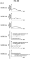
- FIG. 9A is an explanatory diagram showing transitions of the predicted values of the CO 2 discharge amount and the CO 2 concentration of the thermal power station in the area A.
- FIG. 9B is an explanatory diagram showing transitions of predicted values of the CO 2 discharge amounts and the CO 2 concentrations of the factories 31a, 31b, and 31n in the area B.
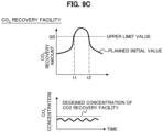
- FIG. 9C is an explanatory diagram showing transitions of the CO 2 recovery amount and the CO 2 concentration in the CO 2 recovery facility.
- FIG. 9D is an explanatory diagram showing transitions of predicted values of the CO 2 discharge amount and the CO 2 concentration of the thermal power station in the area A in the case where the CO 2 concentrating facility is operated.
- the CO 2 discharge amount plan is not particularly changed.
- FIG. 9E is an explanatory diagram showing transitions of predicted values of the CO 2 discharge amounts and the CO 2 concentrations of the factories 31a, 31b, and 31n in the area B in the case where the CO 2 concentrating facility is operated.
- the CO 2 discharge amounts are reviewed in the factories 31a and 31b such that the CO 2 recovery amount in the CO 2 recovery facility 1 is made equal to or lower than the upper limit value Q0 in a time zone including time t1 to t2 (see FIG. 9C ).
- the CO 2 concentrating facilities 8a and 8b(see FIG. 7 ) are operated in a predetermined manner, it is predicted that the concentration of CO 2 discharged from the factories 31a and 31b besides the factory 31n will exceed the designed concentration of the CO 2 recovery facility.
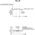
- FIG. 9F is an explanatory diagram showing actual values of the CO 2 recovery amount and the CO 2 concentration in the CO 2 recovery facility.
- the heavy solid line in the graph on the upper side of FIG. 9F indicates the transition of the actual value of the CO 2 recovery amount in the CO 2 recovery facility 1.
- the heavy solid line in the graph on the lower side of FIG. 9F indicates the transition of the actual value of the concentration of CO 2 discharged from the CO 2 recovery facility 1.
- the actual value of the CO 2 recovery amount in the CO 2 recovery facility 1 is made equal to or lower than the predetermined upper limit value Q0.
- the actual value of the concentration of CO 2 discharged from the CO 2 recovery facility 1 exceeds the designed concentration of the CO 2 recovery facility 1. This makes it possible to recover CO 2 efficiently within the ability of the CO 2 recovery facility 1.
- the computation processing device 3 measures and manages the CO 2 concentrations in the carbon detecting units 4p and 4q installed on the outlet side of the CO 2 concentrating facilities 8a and 8b, and changes the operating conditions of the CO 2 concentrating facilities 8a and 8b.
- a carbon detecting unit (not shown) may be provided on an outlet gas conduit (not shown) which is connected to the CO 2 concentrating facilities 8a and 8b, through which a gas other than the concentrated CO 2 flows.
- the third embodiment it becomes possible to reduce the consumed energy of the CO 2 recovery facility 1 and secure the designed purity of recovered CO 2 by increasing the exhaust gas CO 2 concentration.
- the concentrating reduces the flow rate of the exhaust gas from the exhaust gas generation source, the third embodiment also contributes to a reduction in initial cost of conduits.
- a fourth embodiment is different from the third embodiment (see FIG. 7 ) in that a carbon management system 100C (see FIG. 10 ) includes a CO 2 accumulating facility 9 (see FIG. 10 ), and includes a hydrogen producing facility 10 (see FIG. 10 ), a recycling facility 11(see FIG. 10 ), and a CO 2 accumulation flow rate adjusting unit 12(see FIG. 10 ).
- a carbon management system 100C includes a CO 2 accumulating facility 9 (see FIG. 10 ), and includes a hydrogen producing facility 10 (see FIG. 10 ), a recycling facility 11(see FIG. 10 ), and a CO 2 accumulation flow rate adjusting unit 12(see FIG. 10 ).
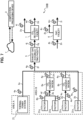
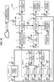
- FIG. 10 is a configuration diagram of a carbon management system 100C according to the fourth embodiment.
- the carbon management system 100C shown in FIG. 10 includes the CO 2 accumulating facility 9, the hydrogen producing facility 10, the recycling facility 11, and the CO 2 accumulation flow rate adjusting unit 12 in addition to the system configuration (see FIG. 7 ) described in the third embodiment.
- the CO 2 accumulating facility 9 is a facility which accumulates CO 2 supplied from the CO 2 recovery facility 1 and is provided downstream of the CO 2 recovery facility 1.
- the hydrogen producing facility 10 is a facility which produces hydrogen by utilizing a renewable energy power and supplies the hydrogen thus produced to the recycling facility 11.
- the recycling facility 11 is a facility which conducts recycling by using CO 2 recovered in the CO 2 recovery facility 1 and the DAC facility 6 as a raw material and utilizing hydrogen supplied from the hydrogen producing facility 10.
- a "conduit" which guides a resource produced in the recycling facility 11 from the recycling facility 11 to the discharge sources is configured to include the conduits 2r and 2u shown in FIG. 10 .
- the CO 2 accumulation flow rate adjusting unit 12 has a function of adjusting the CO 2 supply amount to be supplied from the CO 2 recovery facility 1 to the CO 2 accumulating facility 9.
- a renewable energy is supplied to the hydrogen producing facility 10 of FIG. 10 .
- a chemical product and the like may be produced by a method that does not utilize a renewable energy, or hydrogen may be imported from overseas, and the source of procurement of hydrogen is not limited.
- the substance recycled in the recycling facility 11 includes, for example, methane and ethanol, but there are a wide variety of substances depending on consumers.
- this substance is referred to as the "fuel” or the “resource”, there may be one type of substance or a plurality of types of substances.
- the CO 2 accumulating facility 9 has a function of temporarily or permanently accumulating CO 2 supplied from the CO 2 recovery facility 1.
- temporal accumulation includes a tank which accumulates highly pressurized CO 2 , a tank which accumulates frozen CO 2 , and the like (accumulates a gas or a liquid and in a supercritical state depending on the temperature.
- the method for permanent accumulation includes, for example, a method which liquefies recovered CO 2 and putting CO 2 in a shielding layer from which CO 2 does not leak in the ground, and the like. These are selected as appropriate depending on the operating condition of the system. Note that only temporal accumulation may be used, or only permanent accumulation may be used, or both of two types may be used depending on the circumstances.
- carbon detecting units 4r to 4z which are capable of measuring the concentration in terms of carbon of carbon-containing components in the gas and the flow rate of the exhaust gas is included besides the carbon detecting units 4a to 4q described in the third embodiment (see FIG. 7 ).
- the carbon detecting unit 4r is installed on a conduit 2p which connects the recovered CO 2 side of the CO 2 recovery facility 1 and the recycling facility 11.
- the carbon detecting unit 4s is installed on the outlet side of the recycling facility 11.
- the carbon detecting units 4t to 4z are installed on the inlet sides of the exhaust gas generation source, the chemical product producing facility 13, and the other consumer 14 which utilize the fuel or resource produced in the recycling facility 11.
- the conduit 2d on which the carbon detecting unit 4h is installed is connected to the CO 2 accumulating facility 9.
- the conduit 2i on which the carbon detecting unit 4m is installed is connected to the recycling facility 11.
- a "third detecting unit" which acquires a concentration in terms of carbon of a carbon-containing component in a gas supplied from the recycling facility 11 to at least one of the plurality of discharge sources and a flow rate of the gas is configured to include the carbon detecting units 4s to 4z.
- the computation processing device 3 calculates a fuel use amount or a resource use amount to be used in the exhaust gas generation sources or in production of chemical products from data of the carbon detecting units 4s to 4z acquired by the data collecting system 7, and calculates CO 2 supply amount to the recycling facility 11 from that information.
- the computation processing device 3 calculates the fuel use amount to be used in the discharge sources based on the concentration in terms of carbon of the carbon-containing components in the gas and the flow rate of the gas acquired by the carbon detecting units 4s to 4z (third detecting unit), and calculates the CO 2 supply amount necessary in the recycling facility 11 from the fuel use amount to be used in the discharge sources.
- the computation processing device 3 calculates the flow rate of CO 2 to be supplied to the CO 2 accumulating facility 9 from a difference between the CO 2 recovery amount calculated from data of the carbon detecting unit 4j and the CO 2 supply amount to the recycling facility 11.
- the computation processing device 3 determines the operating condition of the CO 2 accumulation flow rate adjusting unit 12 from the CO 2 supply amount to the recycling facility 11 and the CO 2 supply amount to the CO 2 accumulating facility 9, and instructs the CO 2 accumulation flow rate adjusting unit 12 about the operating condition. That is, the computation processing device 3 sets the operating condition of the CO 2 accumulation flow rate adjusting unit 12 based on a difference between the CO 2 recovery amount in the CO 2 recovery facility 1 and the CO 2 supply amount necessary in the recycling facility 11.
- the computation processing device 3 may have a function of acquiring information on the power supply amount derived from a renewable energy and a demand for a synthetic fuel, and determining the operating condition of the hydrogen producing facility 10 based on these pieces of information. That is, the computation processing device 3 may set the operating condition of the hydrogen producing facility 10 based on the supply amount of the renewable energy power to the hydrogen producing facility 10 and the demand for the synthetic fuel.
- the computation processing device 3 may calculate the amount of carbon (for example, the amount of CO 2 and CO) contained in the synthetic fuel to be supplied to each consumer.
- the fourth embodiment it becomes possible to produce, in the recycling facility 11, a fuel or a resource in an amount necessary in the exhaust gas generation sources and another consumer.
- a method for supplying an appropriate amount of a recycled fuel or resource to an exhaust gas generation source in the case where the operating condition of the exhaust gas generation source has been changed and the amount of the fuel or raw material used has changed will be described. Note that although a variety of products such as a fuel and a resource are produced in the recycling facility 11 (see FIG. 10 ), those will be collectively described as a "fuel" in the fifth embodiment. Note that the configuration of the carbon management system according to the fifth embodiment is the same as in the fourth embodiment (see FIG. 10 ), and the description of each configuration will be omitted.
- the computation processing device 3 calculates the fuel demand amount of the entire system based on data of the carbon detecting units 4t to 4z acquired by the data collecting system 7. In addition, the computation processing device 3 calculates a production amount of the recycled fuel which can be produced in the recycling facility 11 from the fuel use amount and the amount in terms of carbon acquired from the carbon detecting unit 4a to 4f.
- the computation processing device 3 sets the operating condition of the DAC facility 6 such that the CO 2 supply amount additionally necessary in the recycling facility 11 is supplied. Then, the computation processing device 3 causes the necessary amount of CO 2 to be supplied from the DAC facility 6 to the recycling facility 11.
- the computation processing device 3 first calculates a CO 2 recycling facility supply amount necessary in the recycling facility 11 from the fuel use amount acquired from the carbon detecting units 4s to 4z (third detecting unit). Then, the computation processing device 3 sets the operating condition of the DAC facility 6 which recovers CO 2 in the atmosphere such that the CO 2 recycling facility supply amount additionally necessary is supplied to the recycling facility 11, based on a difference between the CO 2 supply amount from the plurality of discharge sources to the CO 2 recovery facility 1 and the CO 2 recycling facility supply amount. This enables such an adjustment that the fuel supply amount detected in the carbon detecting unit 4s coincides with the fuel demand amount of the entire system.
- the supply amount of the recycled fuel produced in the recycling facility 11 is adjusted such that the supply amount coincides with the demand of each exhaust gas generation source or the consumer by the carbon detecting units 4t to 4z.
- the DAC facility 6 is given to supply the CO 2 supply amount additionally necessary in the recycling facility 11, CO 2 in a necessary amount may be supplied from a predetermined CO 2 accumulating facility (not shown).
- the computation processing device 3 calculates the fuel demand amount of the entire system based on data of the carbon detecting units 4s to 4z acquired by the data collecting system 7. In addition, the computation processing device 3 calculates the production amount of the recycled fuel which can be produced in the recycling facility 11 from the fuel use amount and the amount in terms of carbon acquired from the carbon detecting units 4a to 4f.
- the computation processing device 3 sets the operating condition of the CO 2 accumulation flow rate adjusting unit 12 such that an excess amount of CO 2 is accumulated in the CO 2 accumulating facility 9.
- the computation processing device 3 calculates CO 2 recycling facility supply amount necessary in the recycling facility 11 from the fuel use amount acquired from the carbon detecting units 4s to 4z (third detecting unit), and sets the operating condition of the CO 2 accumulation flow rate adjusting unit 12 based on a difference between the CO 2 supply amount and the CO 2 recycling facility supply amount. This allows the flow rate of CO 2 detected in the carbon detecting unit 4h to coincide with a difference between the amounts of carbon detected by the carbon detecting units 4a to 4f and the amount of carbon adjusted to coincide with the demand for the recycled fuel of the entire system.
- the fifth embodiment it becomes possible to control the CO 2 supply amount to the recycling facility 11 to a proper value in the case where the demand for the recycled fuel of each area has increased or decreased.
- the configuration in which CO 2 is supplied to the recycling facility 11 from both of the CO 2 recovery facility 1 and the DAC facility 6 is not limited to this. That is, a configuration is possible in which CO 2 recovered in the CO 2 recovery facility 1 or CO 2 recovered in the DAC facility 6, which recovers CO 2 in the atmosphere, is used as a raw material in the recycling facility 11.
- all or some of programs which achieve the functions of the carbon management system 100 and the like described in each embodiment may be executed by one or a plurality of computers such as a server (not shown). All of some of the above-described programs may be achieved with hardware by designing with integrated circuits to be. In addition, the configurations and functions described in the embodiments may be achieved with software by a processor interpreting and executing programs which achieve the respective functions. Information of programs, tables, files and the like to achieve each function may be stored in a storage apparatus such as a memories, a hard disk, or an SSD (Solid State Drive), or a storage medium such as an IC card, a SD card, a CD-ROM, or a DVD. It is also possible to provide the above-described programs through a communication line.
- a storage apparatus such as a memories, a hard disk, or an SSD (Solid State Drive), or a storage medium such as an IC card, a SD card, a CD-ROM, or a DVD. It is also possible to provide the above-described
- each embodiment has been described in detail for describing the present invention in an easily understandable manner, and is not limited to those including all the described configurations.
- a part of the configuration of each embodiment may be added, deleted, or replaced with another configuration.
- the above-described mechanisms and configurations are shown as those which are considered to be necessary for the description, and all the mechanisms and configurations are not necessarily shown in terms of products.
Landscapes
- Engineering & Computer Science (AREA)
- Business, Economics & Management (AREA)
- Human Resources & Organizations (AREA)
- Economics (AREA)
- Strategic Management (AREA)
- Health & Medical Sciences (AREA)
- Theoretical Computer Science (AREA)
- General Business, Economics & Management (AREA)
- Marketing (AREA)
- Chemical & Material Sciences (AREA)
- General Physics & Mathematics (AREA)
- Tourism & Hospitality (AREA)
- Physics & Mathematics (AREA)
- Entrepreneurship & Innovation (AREA)
- Biomedical Technology (AREA)
- Operations Research (AREA)
- Chemical Kinetics & Catalysis (AREA)
- Oil, Petroleum & Natural Gas (AREA)
- General Chemical & Material Sciences (AREA)
- Analytical Chemistry (AREA)
- Quality & Reliability (AREA)
- Environmental & Geological Engineering (AREA)
- General Health & Medical Sciences (AREA)
- Primary Health Care (AREA)
- Manufacturing & Machinery (AREA)
- Game Theory and Decision Science (AREA)
- Water Supply & Treatment (AREA)
- Public Health (AREA)
- Development Economics (AREA)
- Sustainable Development (AREA)
- Life Sciences & Earth Sciences (AREA)
- Educational Administration (AREA)
- Treating Waste Gases (AREA)
- Carbon And Carbon Compounds (AREA)
Abstract
Description
- The present invention relates to a carbon management system and a computation processing device.
- Although expansion of introduction of renewable energy and electrification of facilities are underway in order to achieve carbon neutral societies, facilities using fossil fuels will remain to a certain extent as predicted by the IEA (International Energy Agency) as well. For this reason, introduction of CO2 reduction technologies is essential. For example, technologies described in
Patent Literatures - Specifically,
Patent Literature 1 discloses a system that converts discharge of CO2 to costs, evaluates the costs of the process path, and proposes an optimum path. - In addition,
Patent Literature 2 discloses an information management system for managing identification information of a user of a CO2 recovery apparatus and information on the CO2 recovery amount, the use application, and use amount among a CO2 collection station, a transport vehicle, a processing factory for converting CO2 into fuel, and an information management center. -
- Patent Literature 1:
US2009/0177505A1 - Patent Literature 2:
JP2021-77028A -
Patent Literatures - In view of this, an object of the present invention is to provide a carbon management system and the like which are capable of adjusting a supply/demand balance of CO2 or a carbon-containing substance.
- To solve the above-described problem, a carbon management system according to the present invention comprises: a plurality of discharge sources which discharge an exhaust gas containing CO2; a CO2 recovery facility which separates and recovers CO2 from the exhaust gas discharged from the plurality of discharge sources; a conduit which is provided between the plurality of discharge sources and the CO2 recovery facility such that the exhaust gas discharged from the discharge sources is collected in the CO2 recovery facility; and a computation processing device which sets an operating condition of at least one of the plurality of discharge sources or an operating condition of the CO2 recovery facility.
- The present invention makes it possible to provide a carbon management system and the like which are capable of adjusting a supply/demand balance of CO2 or a carbon-containing substance.
-
-
FIG. 1 is a configuration diagram of a carbon management system according to a first embodiment. -
FIG. 2 is a flowchart showing processing in the carbon management system according to the first embodiment. -
FIG. 3A is an explanatory diagram of a CO2 discharge amount plan in a case where a CO2 recovery amount is predicted to temporarily exceed an upper limit in a CO2 recovery facility in the carbon management system according to the first embodiment. -
FIG. 3B is an explanatory diagram of the CO2 discharge amount plan after the CO2 discharge amount plan has been reviewed in the carbon management system according to the first embodiment. -
FIG. 3C is an explanatory diagram regarding an actual CO2 discharge amount in the carbon management system according to the first embodiment. -
FIG. 4 is a configuration diagram of a carbon management system according to a second embodiment. -
FIG. 5 is a flowchart showing processing in the carbon management system according to the second embodiment. -
FIG. 6A is an explanatory diagram of a CO2 discharge amount plan in a case where a CO2 recovery amount is predicted to temporarily exceed an upper limit in a CO2 recovery facility in the carbon management system according to the second embodiment. -
FIG. 6B is an explanatory diagram after a CO2 accumulated amount has been reviewed in the carbon management system according to the second embodiment. -
FIG. 6C is an explanatory diagram showing another example after the CO2 accumulated amount has been reviewed in the carbon management system according to the second embodiment. -
FIG. 7 is a configuration diagram of a carbon management system according to a third embodiment. -
FIG. 8 is a flowchart showing processing in the carbon management system according to the third embodiment. -
FIG. 9A is an explanatory diagram showing transitions of predicted values of a CO2 discharge amount and a CO2 concentration of a thermal power station in an area A in the carbon management system according to the third embodiment. -
FIG. 9B is an explanatory diagram showing transitions of predicted values of CO2 discharge amounts and CO2 concentrations of afactories -
FIG. 9C is an explanatory diagram showing transitions of a CO2 recovery amount and a CO2 concentration in a CO2 recovery facility in the carbon management system according to the third embodiment. -
FIG. 9D is an explanatory diagram showing transitions of the predicted values of the CO2 discharge amount and the CO2 concentration of the thermal power station in the area A in a case where a CO2 concentrating facility is operated in the carbon management system according to the third embodiment. -
FIG. 9E is an explanatory diagram showing transitions of predicted values of the CO2 discharge amounts and the CO2 concentrations of thefactories -
FIG. 9F is an explanatory diagram showing actual values of the CO2 recovery amount and the CO2 concentration in the CO2 recovery facility in the carbon management system according to the third embodiment. -
FIG. 10 is a configuration diagram of carbon management systems according to fourth and fifth embodiments. - Hereinafter, each embodiment of the present invention will be described by using the drawings. Note that the same configurations are denoted by the same reference signs, and in the case where a description is repetitive, the description will be omitted in some cases. In addition, the present invention is not limited to each embodiment given below.
- A carbon management system 100 (see
FIG. 1 ) according to one embodiment of the present invention is configured to collect a plurality of exhaust gases containing CO2 in areas such as an industrial park where the exhaust gases containing CO2 are discharged, collectively recover CO2, and supply CO2 to facilities downstream of thecarbon management system 100. This makes it possible to disperse the burden of costs associated with the introduction of CO2 reduction technologies, and further to reduce the load of each element facility and manage supplies and demands. -
FIG. 1 is a configuration diagram of thecarbon management system 100 according to a first embodiment. Thecarbon management system 100 includes: a plurality of discharge sources (athermal power station 21 andfactories 31a to 31n in the example ofFIG. 1 ) which discharge exhaust gases containing CO2 (carbon dioxide); a CO2 recovery facility 1 which collects the exhaust gases discharged from the plurality of discharge sources and separates and recovers CO2 from the collected exhaust gases;conduits 2a to 2c which guide the exhaust gases discharged from the plurality of discharge sources to the CO2 recovery facility 1; and acomputation processing device 3 which sets an operating plan (operating condition) of at least one of the plurality of discharge sources or an operating plan (operating condition) of the CO2 recovery facility 1. The plurality of discharge sources includes, for example, a discharge source which discharges a large amount and a high concentration of CO2 and a discharge source which discharges a smaller amount or a lower concentration of CO2 than the former discharge source. In an area A, there is a discharge source which discharges a large amount and a high concentration of CO2. As such a discharge source, athermal power station 21 is provided in the example ofFIG. 1 . Thethermal power station 21 includes, for example, a gas thermal power station, a coal thermal power station, a steel plant, and the like. Theconduits 2a to 2c are provided between the discharge sources and the CO2 recovery facility 1, and are configured such that the exhaust gases discharged from the plurality of discharge sources are collected in the CO2 recovery facility 1. - Near the area A, there is an area B in which facilities including discharge sources with a lower concentration and a lower discharge amount of CO2 than the discharge source in the area A are gathered. The area B includes, for example, an industrial district, an industrial park, and the like. In the area B, there are
factories 31a to 31n. Businesses in thesefactories 31a to 31n include, for example, the chemical product production industry, the food processing industry, the iron steel industry, the cement industry, and the like. - To the
respective factories 31a to 31n in the area B, theconduits 2b are connected, respectively. Then, the exhaust gas discharged from each of thefactories 31a to 31n and the exhaust gas discharged from thethermal power station 21 flow through theconduit 2b and theconduit 2a, respectively, join together in theconduit 2c, and the exhaust gases thus joined are guided to the CO2 recovery facility 1 by theconduit 2c. That is, the exhaust gases discharged from the area A and the area B are supplied to the CO2 recovery facility 1 through theconduits conduits - The CO2 recovery facility 1 has a function of recovering CO2 in an exhaust gas. The method for recovering CO2 includes, for example, a chemical absorption method which brings an alkaline CO2 absorption liquid and an exhaust gas into contact to cause the CO2 absorption liquid to absorb CO2 in the exhaust gas. Besides, there are a physical adsorption method which uses an adsorption agent utilizing a Van der Waals' force, a chemical adsorption method which brings an alkaline CO2 adsorption material (solid) and an exhaust gas into contact to cause the CO2 adsorption material to adsorb CO2 in the exhaust gas, and the like. The CO2 recovery facility 1 may be installed in a site different from the site of a discharge source, or may be installed in the same site (in the factory) as that of a discharge source. That is, the CO2 recovery facility 1 may be provided in a site in which any of the plurality of discharge sources is disposed.
- Note that the example of
FIG. 1 has a configuration in which theconduit 2a through which the exhaust gas discharged from the area A flows and theconduits 2b through which the exhaust gas discharged from the area B flows are connected to theconduit 2c to be joined, and thereafter the exhaust gases are supplied to the CO2 recovery facility 1, the configuration is not limited to this. For example, the exhaust gas from the area A and the exhaust gas from the area B may be each individually supplied to the CO2 recovery facility 1. Note that it is preferable that the exhaust gases of theconduit 2a of the area A and theconduits 2b of the area B be brought together (joined) at theconduit 2c before the CO2 recovery facility 1, and thereafter be supplied to the CO2 recovery facility 1, because CO2 to be supplied to the CO2 recovery facility 1 can be collectively managed. - By supplying the exhaust gases generated in the plurality of discharge sources to the CO2 recovery facility 1 all together to separate and recover CO2 as in the first embodiment, it becomes possible to reduce the burden of costs associated with a reduction in CO2 discharge amount. In addition, for the owner of the CO2 recovery facility 1, the operating rate of the CO2 recovery facility 1 can be improved.
- As shown in
FIG. 1 , at predetermined portions of theconduits 2a to 2e,carbon detecting units 4a to 4i which are capable of measuring the concentration in terms of carbon of carbon-containing components in an exhaust gas and the flow rate of the exhaust gas are included. In the first embodiment, thecarbon detecting units 4a to 4e are installed near outlets of exhaust gas generation sources (thethermal power station 21 and thefactories 31a to 31n), respectively. In addition, thecarbon detecting unit 4f is installed at a point at which outlet conduits of thefactories carbon detecting unit 4g is installed near an inlet of the CO2 recovery facility 1 (a portion through which the exhaust gases having joined flow). Note that a "first detecting unit" which acquires a concentration in terms of carbon (hereinafter, referred to as a carbon concentration) of a carbon-containing component in an exhaust gas discharged from the discharge sources and a flow rate of the exhaust gas is configured to include thecarbon detecting units 4a to 4g. - The
carbon detecting unit 4h shown inFIG. 1 is installed on theconduit 2d for CO2 which flows out of the CO2 recovery facility 1. In addition, thecarbon detecting unit 4i is installed on theconduit 2e (outlet gas conduit) through which a gas other than CO2 flows out of the CO2 recovery facility 1. Note that a "second detecting unit" which acquires a concentration in terms of carbon of a carbon-containing component in a gas discharged from the CO2 recovery facility 1 and a flow rate of the gas is configured to include thecarbon detecting units - The carbon-containing components in the exhaust gas include CO2, CO, CH4, and the like. The method for measuring a carbon-containing component in an exhaust gas can be achieved by utilizing, for example, a mass analysis, a gas chromatography analysis, an infrared spectroscopy, a cavity-ring-down spectroscopy, or the like. In addition, the flow rate of the exhaust gas can be detected by using a process gas flowmeter, or the like. In addition, the concentration and the flow rate of these carbon components (CO2, CO, CH4) may be calculated based on a fuel use amount of the exhaust gas generation source. By acquiring the concentration in terms of carbon of the carbon-containing component in the exhaust gas, flows of not only CO2 but also carbon-containing substances such as CO and CH4 can be managed.
- Information of the
carbon detecting units 4a to 4i is collected in a data collecting system 7 (database) through a network (not shown). Thecomputation processing device 3 of thecarbon management system 100 is capable of communicating with thedata collecting system 7 through the network (not shown). - The
computation processing device 3 sets operating plans of the CO2 recovery facility 1 and each discharge source by using the information of thecarbon detecting units 4a to 4i collected in thedata collecting system 7. That is, thecomputation processing device 3 has a computation processing function of setting an operating condition of at least one of the plurality of discharge sources or the CO2 recovery facility 1, and a management function of managing at least one of the plurality of discharge sources and the CO2 recovery facility 1, based on data acquired by thecarbon detecting units 4a to 4g (the first detecting unit) and thecarbon detecting units -
FIG. 2 is a flowchart showing processing in the carbon management system (see alsoFIG. 1 as appropriate). - Note that although not particularly shown in
FIG. 2 , it is assumed that "collection processing" of collecting the exhaust gases discharged from the plurality of discharge sources through theconduits 2a to 2c in the CO2 recovery facility 1 and "separation processing" of separating CO2 from the exhaust gases collected in the CO2 recovery facility 1 are conducted. - (a) Step S101: The
computation processing device 3 collects data of a CO2 discharge amount plan from each area in a predetermined period of time. For example, the predetermined period of time is set to 1 month, and thecomputation processing device 3 manages CO2 discharge amounts on a daily basis and a CO2 recovery amount. The exhaust gas generation sources (that is, thethermal power station 21 in the area A and thefactories 31a to 31n in the area B inFIG. 1 ) transmit data of the CO2 discharge amount plans on a daily basis to thecomputation processing device 3. Then, thecomputation processing device 3 registers the CO2 discharge amounts on a daily basis in the exhaust gas generation sources and the CO2 recovery amount. - Moreover, the
computation processing device 3 sets a value obtained by adding up the CO2 discharge amount plans on a daily basis of all the exhaust gas generation sources as a planned initial value of the CO2 recovery amount in the CO2 recovery facility 1 in the computation processing function of setting an operating condition (operating plan) of the CO2 recovery facility 1. - (b) Step S102: The
computation processing device 3 determines whether or not the recovery amount (for example, a recovery amount per day) of CO2 in the CO2 recovery facility 1 exceeds a predetermined upper limit value. If the recovery amount of CO2 does not exceed the upper limit value in step S102 (S102: No), the processing of thecomputation processing device 3 returns to "START". In addition, if the recovery amount of CO2 exceeds the upper limit value in step S102 (S102: Yes), the processing of thecomputation processing device 3 proceeds to step S103. - (c) Step S103: The
computation processing device 3 gives an instruction to review the CO2 discharge amount plans. For example, in the case where there is a period of time (time t1 to t2 inFIG. 3A ) during which this planned initial value exceeds a designed upper limit value for a CO2 amount which can be recovered in the CO2 recovery facility 1, thecomputation processing device 3 instructs the exhaust gas generation sources to review the CO2 discharge amount plans of the period of time (time t1 to t2) during which the CO2 amount exceeds the upper limit value, in the management function for the discharge sources and the CO2 recovery facility 1. That is, thecomputation processing device 3 transmits a predetermined instruction signal regarding the review of the CO2 discharge amount plans to thethermal power station 21 and thefactories 31a to 31n. - The
thermal power station 21 and thefactories 31a to 31n in each area reset the CO2 discharge amount plans based on the instruction (S103) from thecomputation processing device 3, and transmit data of the CO2 discharge amount plans after the resetting to thecomputation processing device 3. Thecomputation processing device 3 acquires data of the CO2 discharge amount plans again (S101). In this way, the CO2 discharge amount plans after the resetting are reregistered in thecomputation processing device 3. - The
computation processing device 3 adds up the CO2 discharge amount plans on a daily basis of all the exhaust gas generation sources again, in the computation processing function of setting the operating condition. If thecomputation processing device 3 determines that the CO2 recovery amount of the CO2 recovery facility does not exceed the designed upper limit (upper limit value) during the predetermined period of time in the management function for the discharge sources and the CO2 recovery facility 1 (S103: No), thecomputation processing device 3 determines that an operating preparation of the CO2 recovery facility 1 is completed, and proceeds to the processing of step S104. - (d) Step S104: The
computation processing device 3 sets an operating condition of the CO2 recovery facility 1 (computation processing). Thecomputation processing device 3 measures discharged CO2 amounts of thecarbon detecting units 4a to 4e included on theconduits carbon detecting units 4a to 4e. If thecomputation processing device 3 determines that a detected value of the CO2 discharge amount exceeds the replanned value, although omitted inFIG. 2 , thecomputation processing device 3 specifies a carbon detecting unit which has caused the detected value to exceed the planned value, and notifies an exhaust gas generation source associated with the specified carbon detecting unit to further reduce the discharged CO2 amount and of the reduction amount. - In addition, the
computation processing device 3 manages the replanned value and the detected value of the CO2 recovery amount in the CO2 recovery facility 1. In the case where the detected value of the CO2 amount is about to exceed the upper limit value (for example, in the case where the CO2 amount has increased to reach a predetermined value which is smaller than the upper limit value), thecomputation processing device 3 specifies a carbon detecting unit which has caused the detected value to be about to exceed the planned value. Then, thecomputation processing device 3 notifies an exhaust gas generation source (thethermal power station 21 or thefactory 31a to 31n) associated with the specified carbon detecting unit to further reduce the discharged CO2 amount and of the reduction amount. - Note that the detected value of the CO2 recovery amount in the computation processing function of setting the operating condition of the CO2 recovery facility 1 is calculated from measured values of the CO2 concentration in the exhaust gases in the
carbon detecting units FIG. 1 and the amounts of the exhaust gases. For example, the CO2 recovery amount can be obtained from the CO2 recovery amount=(the amount of the exhaust gas in thecarbon detecting unit 4g×the CO2 concentration in thecarbon detecting unit 4g)-(the amount of the exhaust gas in thecarbon detecting unit 4i×the CO2 concentration in thecarbon detecting unit 4i), or the CO2 recovery amount=(the amount of the exhaust gas in thecarbon detecting unit 4h×the CO2 concentration in thecarbon detecting unit 4h). - The exhaust gas generation source which has been notified to reduce the CO2 discharge amount and the reduction amount reduces the CO2 discharge amount. The
computation processing device 3 checks whether or not this exhaust gas generation source has reduced the CO2 discharge amount from information of the carbon detecting unit. In this way, thecomputation processing device 3 calculates the CO2 supply amount to be supplied from the plurality of discharge sources to the CO2 recovery facility 1 and calculates a reduction amount of the CO2 discharge amount to be discharged from the discharge sources such that the CO2 supply amount to be supplied to the CO2 recovery facility 1 falls within a designed value of the CO2 recovery facility 1, based on the carbon concentrations and the flow rates of the exhaust gases acquired by thecarbon detecting units 4a to 4g (first detecting unit). -
FIG. 3A is an explanatory diagram of a CO2 discharge amount plan in the case where the CO2 recovery amount in a CO2 recovery facility is predicted to temporarily exceed the upper limit. - Note that five graphs in total included in
FIG. 3A indicate the transition of the CO2 discharge amount in thethermal power station 21 in the area A, transitions of the CO2 discharge amounts in thefactories thermal power station 21 and thefactories FIG. 3A , it is predicted that the CO2 recovery amount will exceed a predetermined upper limit value Q0 in a time zone of time t1 to t2 in the CO2 recovery facility 1. -
FIG. 3B is an explanatory diagram of the CO2 discharge amount plan after the CO2 discharge amount plan has been reviewed. - In the example of
FIG. 3B , the CO2 discharge amount plans are reviewed in thefactories FIG. 2 ) from thecomputation processing device 3. This makes the CO2 recovery amount (replanned value) in the CO2 recovery facility 1 equal to or lower than the predetermined upper limit value Q0. -
FIG. 3C is an explanatory diagram regarding actual CO2 discharge amounts. - Note that the heavy lines in each graph of
FIG. 3 indicates the detected values of the CO2 discharge amounts and the CO2 recovery amount. - If the
computation processing device 3 has determined that the detected value of the CO2 discharge amount exceeded the replanned value in each discharge source, thecomputation processing device 3 notifies the discharge source to further reduce the CO2 discharge amount and of the reduction amount as described above. - As described above, the
carbon management system 100 according to the first embodiment includes thecomputation processing device 3 which communicates with the CO2 recovery facility 1 which collects exhaust gases discharged from the plurality of discharge sources through theconduits 2a to 2g and separates CO2 from the collected exhaust gases. Thecomputation processing device 3 sets an operating condition of at least one of the plurality of discharge sources or an operating condition of the CO2 recovery facility. With such a configuration, thecomputation processing device 3 can determine whether or not the CO2 discharge amount from each discharge source should be adjusted based on the designed upper limit value of the CO2 recovery facility 1 and the CO2 discharge plans of the discharge sources and instruct the discharge source to reduce the CO2 discharge amount. - In addition, if CO2 reduction technologies were introduced individually, the burden of costs would increase. However, in the first embodiment, since exhaust gases are collected in an industrial park or the like and collectively recovered, it becomes possible to disperse the burden of costs associated with the introduction of CO2 reduction technologies. Then, by making the CO2 supply amounts of the CO2 recovery facility 1, the recycling facility, and the like fall within a design range, and adjusting the supply and demand, it is possible to reduce the operating load and secure the purity of products and the supply/demand balance. In this way, the first embodiment makes it possible to provide a
carbon management system 100 which can adjust the supply/demand balance of CO2 or a carbon-containing substance. Note that the "carbon-containing substance" includes CO2 as well. - A second embodiment is different from the first embodiment in that an exhaust gas accumulating facility (see
FIG. 4 ) is provided between a plurality of discharge sources and a CO2 recovery facility 1 (seeFIG. 4 ). In addition, the second embodiment is different from the first embodiment in that a DAC facility 6 (seeFIG. 4 ) is provided. Note that the other configurations are the same as in the first embodiment. Hence, portions different from the first embodiment will be described, and repetitive descriptions of the same portions will be omitted. -
FIG. 4 is a configuration diagram of acarbon management system 100A according to the second embodiment. - In the second embodiment, a method for controlling a CO2 supply amount such that the CO2 recovery amount of the CO2 recovery facility 1 can be made equal to or lower than the upper limit value without particularly changing the CO2 discharge amount plans of exhaust gas generation sources in the case where each exhaust gas generation source as described in the first embodiment cannot flexibly change the CO2 discharge amount plan will be described.
- The
carbon management system 100A shown inFIG. 4 includes an exhaust gas accumulating facility 5 (exhaust gas storing unit) provided between discharge sources which discharge CO2 and the CO2 recovery facility 1 and further includes a DAC(Direct Air Capture)facility 6 provided at any desired location in addition to the same configurations as those of the first embodiment. Note that forms of connections of conduits connecting each facility such as the discharge sources, the CO2 recovery facility 1, and thecarbon detecting units 4a to 4i are the same as in the first embodiment. - The exhaust
gas accumulating facility 5 has a function of accumulating exhaust gases from discharge sources such as thethermal power station 21 and thefactories 31a to 31n. A predetermined upper limit value is set for an exhaust gas accumulated amount in the exhaustgas accumulating facility 5, and the exhaust gas accumulated amount is managed so as not to exceed the upper limit value. For example, the amount of exhaust gas present in the exhaustgas accumulating facility 5 is calculated from the pressure inside the exhaustgas accumulating facility 5 and relations between the supply amount and the release amount of the exhaust gas in the exhaustgas accumulating facility 5. As shown inFIG. 4 , the exhaustgas accumulating facility 5 is connected to aconduit 2f at which exhaust gases from the respective discharge sources of CO2 join. Then, the exhaust gas accumulated in the exhaustgas accumulating facility 5 is guided to the CO2 recovery facility 1 through aconduit 2g. Note that the exhaust gas accumulating facility may be individually installed downstream of each discharge source, and the installation locations and the number of exhaust gas accumulating facilities installed are not limited. In addition, the conduit itself which connects the discharge sources and the CO2 recovery facility 1 may be regarded as the exhaust gas accumulating facility, and the form of installation is not particularly limited. - The
DAC facility 6 has a function of recovering CO2 in the atmosphere. The recovery method of theDAC facility 6 may be the same as that of the CO2 recovery facility 1. That is, the method for recovering the CO2 includes a chemical absorption method which brings an alkaline CO2 absorption liquid and an exhaust gas into contact to cause the CO2 absorption liquid to absorb CO2 in the exhaust gas, a physical adsorption method which uses an adsorption agent utilizing a Van der Waals' force, a chemical adsorption method which brings an alkaline CO2 adsorption material (solid) and an exhaust gas into contact to cause the CO2 adsorption material to adsorb CO2 in the exhaust gas, and the like. Note that aconduit 2h on the inlet side of theDAC facility 6 may be connected to, for example, any of theconduits 2a to 2g or may be connected to another predetermined portion. - As shown in
FIG. 4 , thecarbon management system 100A further includescarbon detecting units 4j to 4n which are capable of measuring the concentration in terms of carbon of carbon-containing components in an exhaust gas and the flow rate of the exhaust gas in addition to thecarbon detecting units 4a to 4i described in the first embodiment. Thecarbon detecting unit 4j is installed on theconduit 2g on the outlet side of the exhaustgas accumulating facility 5. In addition, thecarbon detecting unit 4k is installed on theconduit 2h on the inlet side of theDAC facility 6. Thecarbon detecting unit 4m is installed on aconduit 2i which guides recovered CO2 flowing out of theDAC facility 6. Thecarbon detecting unit 4n is installed on aconduit 2k (outlet gas conduit) which guides a gas other than the recovered CO2 flowing out of theDAC facility 6. - Data detected by these
carbon detecting units 4a to 4n is collected to thedata collecting system 7 which is connected to thecomputation processing device 3 like the first embodiment. -
FIG. 5 is a flowchart showing processing in the carbon management system (see alsoFIG. 4 as appropriate). - Note that steps S201, S202, and S204 of
FIG. 5 are the same as steps S101, S102, and S104 of the first embodiment (seeFIG. 2 ) in this order. - (a) Step S201: The
computation processing device 3 collects a CO2 discharge amount plan from each area in a predetermined period of time. For example, the predetermined period of time is set to 1 month, and thecomputation processing device 3 manages the CO2 discharge amounts on a daily basis and the CO2 recovery amount. The exhaust gas generation sources (that is, thethermal power station 21 in the area A and thefactories 31a to 31n in the area B inFIG. 4 ) transmit data of the CO2 discharge amount plans on a daily basis to thecomputation processing device 3. Then, thecomputation processing device 3 registers the CO2 discharge amounts on a daily basis in the exhaust gas generation sources and the CO2 recovery amount. - Moreover, the
computation processing device 3 sets a value obtained by adding up the CO2 discharge amount plans on a daily basis of all the exhaust gas generation sources as a planned initial value of the CO2 recovery amount in the CO2 recovery facility 1 in the computation processing function of setting operating conditions (operating plans) of the exhaustgas accumulating facility 5 and the like. - (b) Step S202: The
computation processing device 3 determines whether or not the recovery amount (for example , a recovery amount per day) of CO2 in the CO2 recovery facility 1 exceeds a predetermined upper limit value. If the recovery amount of CO2 does not exceed the upper limit value in step S202 (S202: No), the processing of thecomputation processing device 3 returns to "START". In addition, if the recovery amount of CO2 exceeds the upper limit value in step S202 (S202: Yes), the processing of thecomputation processing device 3 proceeds to step S203. - (c): step S203: The
computation processing device 3 instructs the exhaustgas accumulating facility 5 about an accumulated amount of the exhaust gas. If there is a period of time (time t1 to t2 inFIG. 4 ) during which the planned initial value of the CO2 recovery facility 1 exceeds an upper limit value for a CO2 amount which can be recovered in the CO2 recovery facility 1 in the management function for the exhaust gas accumulating facility 5 (S202: Yes), thecomputation processing device 3 instructs the exhaustgas accumulating facility 5 to accumulate the exhaust gas such that the planned initial value falls within the upper limit value (S203). Specifically, thecomputation processing device 3 transmits a predetermined instruction signal which requests review of the accumulated amount of CO2 to the exhaustgas accumulating facility 5. - (d) Then, although omitted in
FIG. 5 , thecomputation processing device 3 acquires actual values of CO2 discharge amounts of the discharge sources of each area from thecarbon detecting units 4a to 4n, and supplies the exhaust gas to the exhaustgas accumulating facility 5 in accordance with the operating condition of the exhaustgas accumulating facility 5. At this time, in the case where an increase or decrease from the plans in terms of the amounts of exhaust gases of the discharge sources is found from data from thecarbon detecting units computation processing device 3 changes the operating plan of the exhaustgas accumulating facility 5 as appropriate depending on the increase or decrease. Note that in a time zone (t<t1, t>t2 inFIG. 6A ) in which the planned initial value of the CO2 recovery facility 1 is equal to or less than the designed upper limit, the exhaust gas accumulated in the exhaustgas accumulating facility 5 may be supplied to an extent that does not exceed the designed upper limit value of the CO2 recovery facility 1. - Since an exhaust gas is larger in volume than CO2 to be recovered, there is a case where it is difficult to install the exhaust
gas accumulating facility 5 depending on the scale of discharge sources. In view of this, the method for using theDAC facility 6 will be described below. Note that this method is omitted in the flowchart ofFIG. 5 . - If the CO2 recovery amount of the CO2 recovery facility 1 exceeds the designed upper limit value at the time of planning in step S202, the
computation processing device 3 instructs theDAC facility 6 to recover CO2 in an amount corresponding to the excess from the designed upper limit value in a time zone during which the amount exceeds the upper limit value. Although theDAC facility 6 recovers CO2 in accordance with the plan, if the amount of exhaust gases from the discharge sources is larger than the plan, the operating condition of theDAC facility 6 is changed as appropriate. Note that regarding this time zone (t1 to t2 inFIG. 6A ), the exhaust gas in an amount equal to or more than the designed value may be released to the atmosphere without being supplied to the CO2 recovery facility 1, for example. In addition, since there is a case where a CO2 accumulating facility or a CO2 recycling facility, for example, is included downstream of the CO2 recovery facility 1 or theDAC facility 6, the operation of the downstream facilities can be made easier by making the CO2 recovery amount constant as much as possible. For this reason, the operating time of theDAC facility 6 is preferably set out of the time zone (t1 to t2) ofFIG. 6A described next. -
FIG. 6A is an explanatory diagram of a CO2 discharge amount plan in the case where the CO2 recovery amount in a CO2 recovery facility is predicted to temporarily exceed the upper limit. Note thatFIG. 6A is similar toFIG. 3A used in the description of the first embodiment, and it is predicted that the CO2 recovery amount will exceed the predetermined upper limit value Q0 in a time zone of time t1 to t2 in the CO2 recovery facility 1. In such a case, thecomputation processing device 3 transmits a predetermined instruction signal to the exhaustgas accumulating facility 5 such that the CO2 recovery amount at each time is made to be equal to or lower than the upper limit value Q0. -
FIG. 6B is an explanatory diagram after the CO2 accumulated amount has been reviewed. - As shown in
FIG. 6B , the CO2 recovery amount in the CO2 recovery facility 1 is made to be equal to or lower than the upper limit value Q0 and transitions near the upper limit value Q0 by adjusting the CO2 accumulated amount at each time in the exhaustgas accumulating facility 5. Note that thethermal power station 21 in the area A and thefactories 31a to 31n in the area B can be operated without particularly changing the initial CO2 discharge amount plans (seeFIG. 6A ). -
FIG. 6C is an explanatory diagram showing another example after the CO2 accumulated amount has been reviewed. - In the example of
FIG. 6C , in the time zone t1 to t2 during which the CO2 recovery amount in the CO2 recovery facility 1 exceeds the predetermined upper limit value Q0 in accordance with the initial CO2 discharge amount plan (seeFIG. 6A ), an amount of exhaust gas corresponding to this excess is accumulated in the exhaustgas accumulating facility 5. With such processing as well, the CO2 recovery amount in the CO2 recovery facility 1 can be made to be equal to or lower than the upper limit value Q0. - Note that the detected value of the CO2 accumulated amount in the computation processing function of setting the operating condition of the exhaust
gas accumulating facility 5 is calculated from measured values of the CO2 concentrations in the gases and the gas amounts of thecarbon detecting units FIG. 4 . For example, the CO2 accumulated amount of the exhaustgas accumulating facility 5 can be obtained in accordance with the CO2 accumulated amount=(the gas amount in thecarbon detecting unit 4g×the CO2 concentration in thecarbon detecting unit 4g)-(the gas amount in thecarbon detecting unit 4j×the CO2 concentration in thecarbon detecting unit 4j). Note that the CO2 accumulated amount of the exhaustgas accumulating facility 5 can be calculated by a method that does not use a carbon detecting unit, for example, based on a detected value of a manometer (not shown) provided in the exhaustgas accumulating facility 5. - The
computation processing device 3 calculates a CO2 supply amount from the plurality of discharge sources to the CO2 recovery facility 1 based on the carbon concentrations and the flow rates of the exhaust gases acquired by thecarbon detecting units 4a to 4g (first detecting unit). Then, in the case where the CO2 recovery amount exceeds the designed value (upper limit value) of the CO2 recovery facility 1, thecomputation processing device 3 causes the exhaust gas accumulating facility 5 (exhaust gas storing unit) to temporarily store the exhaust gas in an amount corresponding to this excess of the designed value. Thereafter, in the case where the CO2 supply amount has become equal to or lower than the designed value of the CO2 recovery facility 1, thecomputation processing device 3 sets the operating condition of the exhaustgas accumulating facility 5 such that the exhaust gas is supplied from the exhaustgas accumulating facility 5 to the CO2 recovery facility 1 to an extent that the amount does not exceed the designed value of the CO2 recovery facility 1. - In addition, the detected value of the CO2 recovery amount in the computation processing function of setting the operating condition of the
DAC facility 6 is calculated from the measured values of the CO2 concentrations in the gases and the gas amounts of thecarbon detecting units FIG. 4 . For example, the detected value of the CO2 recovery amount can be obtained in accordance with the CO2 recovery amount=(the gas amount in thecarbon detecting unit 4k×the CO2 concentration in thecarbon detecting unit 4k)-(the gas amount in thecarbon detecting unit 4n×the CO2 concentration in thecarbon detecting unit 4n),or the CO2 recovery amount=(the gas amount in thecarbon detecting unit 4m×the CO2 concentration in thecarbon detecting unit 4m). - The
computation processing device 3 calculates the CO2 supply amount from the plurality of discharge sources to the CO2 recovery facility 1 based on the carbon concentrations and the flow rates of the exhaust gases acquired by thecarbon detecting units 4a to 4g (first detecting unit). Then, in the case where the CO2 supply amount exceeds the designed value (the upper limit value) of the CO2 recovery facility 1, thecomputation processing device 3 supplies the exhaust gas only in an amount equal to the designed value of the CO2 recovery facility 1 from the plurality of discharge sources to the CO2 recovery facility 1. Moreover, thecomputation processing device 3 calculates an excess CO2 amount by which the CO2 supply amount exceeds the designed value of the CO2 recovery facility 1 from the CO2 supply amount and the designed value, and sets the operating condition of theDAC facility 6 such that the excess CO2 amount is recovered. - In the second embodiment, although the control method in the case where the discharge source of each area cannot flexibly change the CO2 discharge amount plan, the configuration is not limited to this. For example, the second embodiment can be applied also in the case where the discharge source of each area can change the CO2 discharge amount plan as in the first embodiment, and the conditions are not limited.
- The above-described configuration makes it possible to make the CO2 recovery amount equal to or lower than the designed upper limit value of the CO2 recovery facility 1 even in the case where the exhaust gas is supplied to the CO2 recovery facility 1 without changing the CO2 discharge amount plan of the discharge source in each area.
- A third embodiment is different from the second embodiment in that CO2 concentrating facilities 8a and 8b (a CO2 concentration adjusting facility: see
FIG. 7 ) are provided between a plurality of discharge sources and an exhaust gas accumulating facility 5 (seeFIG. 7 ). Note that the other configurations are the same as in the second embodiment. Hence, portions different from the second embodiment will be described, and repetitive descriptions of the same portions will be omitted. -
FIG. 7 is a configuration diagram of acarbon management system 100B according to the third embodiment. - The CO2 recovery facility 1 (see
FIG. 7 ) is designed on the assumption of the CO2 concentration of a gas supplied from an inlet in general, and if the CO2 concentration in a supplied gas falls below the assumed CO2 concentration, there is a possibility that the consumed energy in separating CO2 in the CO2 recovery facility 1 increases or the concentration of CO2 recovered at the outlet decreases. In addition, if the amount of an exhaust gas from a discharge source is large, the conduit connecting the discharge source in each area and the CO2 recovery facility 1 or the exhaustgas accumulating facility 5 needs to be designed to be large in conformity with the amount. From the above, it is desirable to increase the CO2 concentration of an exhaust gas before being supplied to a conduit in the case where the CO2 concentration of the exhaust gas discharged from a discharge source falls below the designed value of the CO2 recovery facility 1 in particular for reducing the operating load of the CO2 recovery facility 1 or reducing the initial cost of the conduit. In the third embodiment, a method for solving such problems will be described. -
FIG. 7 shows that the third embodiment further includes CO2 concentrating facilities 8a and 8b (CO2 concentration adjusting facility) provided between each discharge source in the area B and the exhaustgas accumulating facility 5 in addition to the system configuration (seeFIG. 4 ) of the second embodiment. Note that the configurations of the elements other than the CO2 concentrating facilities 8a and 8b and the connection forms are the same as in the second embodiment. In addition, the method for controlling the amount of CO2 to be supplied to the CO2 recovery facility 1 such that the amount becomes equal to or lower than the designed upper limit value of the CO2 recovery facility 1 is also the same as in the second embodiment, and the description will be omitted. - The CO2 concentrating facilities 8a and 8b are facilities which adjusts the CO2 concentration of the exhaust gas discharged from at least one of the plurality of discharge sources (the
factory FIG. 7 ), and are provided between the plurality of discharge sources and the CO2 recovery facility 1. These CO2 concentrating facilities 8a and 8b have a function of increasing the CO2 concentration in the exhaust gases. For example, such a function includes a method for improving the CO2 concentration by separating CO2 with a CO2 separation membrane and adding the CO2 to an exhaust gas of another discharge source besides a N2 separation membrane for separating N2 which is an exhaust gas component other than CO2 and the method for recovering CO2 in the CO2 recovery facility 1 described in the first embodiment. In addition, for example, the CO2 concentration may be adjusted by separating CO2 with a CO2 separation membrane, and providing a conduit (not shown) which bypasses one CO2 concentrating facility to join a concentrated CO2 gas and the exhaust gas flowing through the bypass, besides the method for recovering CO2 in the CO2 recovery facility 1 described in the first embodiment. - The CO2 concentrating facilities 8a and 8b may be installed downstream of each discharge source, or may be installed in a location where the exhaust gases of the plurality of discharge sources join, and the installation locations are not limited. In addition, the CO2 concentrating facilities may be installed for all the discharge sources, or may be installed only for a discharge source which is constantly discharging an exhaust gas with a concentration equal to or lower than the designed CO2 concentration of the CO2 recovery facility 1, for example. The number and locations of the CO2 concentrating facilities installed are not limited.
- As shown in
FIG. 7 , acarbon detecting unit 4p is installed on aconduit 2m downstream of the CO2 concentrating facility 8a, and acarbon detecting unit 4q is installed on aconduit 2n downstream of the CO2 concentrating facility 8b. Thecarbon detecting units carbon detecting units data collecting system 7 connected to thecomputation processing device 3 as in the first embodiment and the second embodiment. -
FIG. 8 is a flowchart showing processing in the carbon management system (see alsoFIG. 7 as appropriate). - Note that steps S301 and S304 of
FIG. 8 are the same as steps S101 and S104 of the first embodiment (seeFIG. 2 ) in this order. -
- (a) Step S301: The
computation processing device 3 collects a CO2 discharge amount plan (exhaust gas flow rate plan) from each area in a predetermined period of time, and predicts the CO2 recovery amount and the CO2 concentration of the CO2 recovery facility 1. For example, the predetermined period of time is set to 1 month, and thecomputation processing device 3 manages the CO2 discharge amounts on a daily basis, the CO2 recovery amount, and the CO2 concentration, The exhaust gas generation sources (that is, thethermal power station 21 in the area A and thefactories 31a to 31n in the area B inFIG. 7 ) transmit data of the CO2 discharge amount plans on a daily basis and the exhaust gas flow rate plans to thecomputation processing device 3. Then, thecomputation processing device 3 registers the CO2 discharge amount plans on a daily basis and the exhaust gas flow rate plans. - In addition, the
computation processing device 3 sets a CO2 concentration in an inlet of the CO2 recovery facility 1 as a planned initial value based on the CO2 recovery amount and the flow rate of the exhaust gas collected from each exhaust gas generation source in the CO2 recovery facility 1 in a computation processing function of setting operating conditions of the CO2 concentrating facilities 8a and 8b. - (b) Step S302: The
computation processing device 3 determines whether or not the CO2 concentration on the inlet side of the CO2 recovery facility 1 is less than a designed CO2 concentration. If the CO2 concentration on the inlet side of the CO2 recovery facility 1 is equal to or more than the designed CO2 concentration (S302: No), the processing of thecomputation processing device 3 proceeds to step S304. In step S304, thecomputation processing device 3 sets an operating condition of each facility to a predetermined condition. In addition, if the CO2 concentration on the inlet side of the CO2 recovery facility 1 is less than the designed CO2 concentration in the management function for the CO2 concentrating facilities 8a and 8b (S302: Yes), the processing of thecomputation processing device 3 proceeds to step S303. - (c) Step S303: The
computation processing device 3 transmits a predetermined operating instruction to the CO2 concentrating facilities 8a and 8b. That is, thecomputation processing device 3 transmits the operating instruction to the CO2 concentrating facilities 8a and 8b such that the CO2 concentration exceeds the designed CO2 concentration of the CO2 recovery facility 1. At this time, the CO2 concentration only has to be equal to or more than the designed CO2 concentration on the inlet side of the CO2 recovery facility 1, and the CO2 concentration does not particularly need to be equal to or more than the designed CO2 concentration on the outlet side of all the CO2 concentrating facilities 8a and 8b. In addition, like the second embodiment, theDAC facility 6 may be notified of a predetermined operating condition based on each management function of thecomputation processing device 3 in addition to the exhaust gas generation sources and the exhaustgas accumulating facility 5 such that the CO2 recovery amount in the CO2 recovery facility 1 does not exceed the designed upper limit value along with the above-described operating instruction. - Then, although omitted in
FIG. 8 , thecomputation processing device 3 acquires actual values of the flow rates of CO2 and the CO2 concentrations of the CO2 concentrating facilities 8a and 8b and the CO2 recovery facility 1 in addition to the exhaust gas generation source of each area from thecarbon detecting units 4a to 4q, and operates each facility in accordance with the operating condition of the CO2 concentrating facility. At this time, in the case where an increase or decrease in the actual values of the exhaust gas amount and the CO2 concentration from the discharge sources relative to the planned values is found from data from thecarbon detecting units computation processing device 3 changes the operating conditions of the CO2 concentrating facilities 8a and 8b as appropriate such that the CO2 concentration on the inlet side of the CO2 recovery facility 1 becomes equal to or more than the designed value (designed CO2 concentration) depending on the increase or decrease. - In this way, the
computation processing device 3 sets the operating conditions of the CO2 concentrating facilities 8a and 8b (CO2 concentration adjusting facility) such that the carbon concentration in the exhaust gas to be supplied to the CO2 recovery facility 1 falls within a set numerical range based on the carbon concentrations acquired by thecarbon detecting units 4a to 4g (first detecting unit). -
FIG. 9A is an explanatory diagram showing transitions of the predicted values of the CO2 discharge amount and the CO2 concentration of the thermal power station in the area A. - In the example of
FIG. 9A , it is predicted that after the CO2 discharge amount of the thermal power station 21 (seeFIG. 7 ) in the area A increases, the CO2 discharge amount will turn to decrease. In addition, it is predicted that the concentration of CO2 discharged from the thermal power station 21 (seeFIG. 7 ) will exceed the designed concentration of the CO2 recovery facility 1. -
FIG. 9B is an explanatory diagram showing transitions of predicted values of the CO2 discharge amounts and the CO2 concentrations of thefactories - As shown in
FIG. 9B , it is predicted that the CO2 discharge amounts of thefactories FIG. 7 ) in the area B will increase and decrease to a certain extent. In addition, although the concentration of CO2 discharged from thefactory 31n exceeds the designed concentration of the CO2 recovery facility 1, it is predicted that the concentrations of CO2 discharged from thefactories -
FIG. 9C is an explanatory diagram showing transitions of the CO2 recovery amount and the CO2 concentration in the CO2 recovery facility. - In the example of
FIG. 9C , it is predicted that the CO2 recovery amount in the CO2 recovery facility 1 will exceed a predetermined upper limit value Q0 in a time zone of time t1 to t2. In addition, it is predicted that the CO2 concentration in the CO2 recovery facility 1 will fall below a predetermined designed concentration. -
FIG. 9D is an explanatory diagram showing transitions of predicted values of the CO2 discharge amount and the CO2 concentration of the thermal power station in the area A in the case where the CO2 concentrating facility is operated. - Regarding the thermal power station 21 (see
FIG. 7 ) in the area A, since the CO2 concentration has exceeded the designed concentration of the CO2 recovery facility 1 in the first place, the CO2 discharge amount plan is not particularly changed. -
FIG. 9E is an explanatory diagram showing transitions of predicted values of the CO2 discharge amounts and the CO2 concentrations of thefactories - In the example of
FIG. 9E , the CO2 discharge amounts are reviewed in thefactories FIG. 9C ). In addition, since the CO2 concentrating facilities 8a and 8b(seeFIG. 7 ) are operated in a predetermined manner, it is predicted that the concentration of CO2 discharged from thefactories factory 31n will exceed the designed concentration of the CO2 recovery facility. -
FIG. 9F is an explanatory diagram showing actual values of the CO2 recovery amount and the CO2 concentration in the CO2 recovery facility. - Note that the heavy solid line in the graph on the upper side of
FIG. 9F indicates the transition of the actual value of the CO2 recovery amount in the CO2 recovery facility 1. In addition, the heavy solid line in the graph on the lower side ofFIG. 9F indicates the transition of the actual value of the concentration of CO2 discharged from the CO2 recovery facility 1. As shown inFIG. 9F , the actual value of the CO2 recovery amount in the CO2 recovery facility 1 is made equal to or lower than the predetermined upper limit value Q0. In addition, the actual value of the concentration of CO2 discharged from the CO2 recovery facility 1 exceeds the designed concentration of the CO2 recovery facility 1. This makes it possible to recover CO2 efficiently within the ability of the CO2 recovery facility 1. - The description will be continued referring back to
FIG. 7 again. Thecomputation processing device 3 measures and manages the CO2 concentrations in thecarbon detecting units computation processing device 3 updates the operating conditions of the CO2 concentrating facilities 8a and 8b as appropriate based on the detected values and the like. - In this way, according to the third embodiment, it becomes possible to reduce the consumed energy of the CO2 recovery facility 1 and secure the designed purity of recovered CO2 by increasing the exhaust gas CO2 concentration. In addition, since the concentrating reduces the flow rate of the exhaust gas from the exhaust gas generation source, the third embodiment also contributes to a reduction in initial cost of conduits.
- A fourth embodiment is different from the third embodiment (see
FIG. 7 ) in that a carbon management system 100C (seeFIG. 10 ) includes a CO2 accumulating facility 9 (seeFIG. 10 ), and includes a hydrogen producing facility 10 (seeFIG. 10 ), a recycling facility 11(seeFIG. 10 ), and a CO2 accumulation flow rate adjusting unit 12(seeFIG. 10 ). Note that the other configurations are the same as in the third embodiment. Hence portions different from the third embodiment will be described, and repetitive description of the same portions will be omitted. -
FIG. 10 is a configuration diagram of a carbon management system 100C according to the fourth embodiment. - In the fourth embodiment, a method for operating a
recycling facility 11, a CO2 accumulating facility 9, and the like will be described. - The carbon management system 100C shown in
FIG. 10 includes the CO2 accumulating facility 9, thehydrogen producing facility 10, therecycling facility 11, and the CO2 accumulation flowrate adjusting unit 12 in addition to the system configuration (seeFIG. 7 ) described in the third embodiment. The CO2 accumulating facility 9 is a facility which accumulates CO2 supplied from the CO2 recovery facility 1 and is provided downstream of the CO2 recovery facility 1. - The
hydrogen producing facility 10 is a facility which produces hydrogen by utilizing a renewable energy power and supplies the hydrogen thus produced to therecycling facility 11. Therecycling facility 11 is a facility which conducts recycling by using CO2 recovered in the CO2 recovery facility 1 and theDAC facility 6 as a raw material and utilizing hydrogen supplied from thehydrogen producing facility 10. As units for supplying recycled fuel to thethermal power station 21 and thefactories 31a to 31n, which are exhaust gas generation sources, or to the chemicalproduct producing facility 13 and theother consumer 14,conduits recycling facility 11 from therecycling facility 11 to the discharge sources is configured to include theconduits FIG. 10 . - The CO2 accumulation flow
rate adjusting unit 12 has a function of adjusting the CO2 supply amount to be supplied from the CO2 recovery facility 1 to the CO2 accumulating facility 9. Note that the configuration is not limited to this configuration in which a renewable energy is supplied to thehydrogen producing facility 10 ofFIG. 10 . For example, a chemical product and the like may be produced by a method that does not utilize a renewable energy, or hydrogen may be imported from overseas, and the source of procurement of hydrogen is not limited. - The substance recycled in the
recycling facility 11 includes, for example, methane and ethanol, but there are a wide variety of substances depending on consumers. In the fourth embodiment, this substance is referred to as the "fuel" or the "resource", there may be one type of substance or a plurality of types of substances. - The CO2 accumulating facility 9 has a function of temporarily or permanently accumulating CO2 supplied from the CO2 recovery facility 1. Examples of temporal accumulation includes a tank which accumulates highly pressurized CO2, a tank which accumulates frozen CO2, and the like (accumulates a gas or a liquid and in a supercritical state depending on the temperature. In addition, the method for permanent accumulation includes, for example, a method which liquefies recovered CO2 and putting CO2 in a shielding layer from which CO2 does not leak in the ground, and the like. These are selected as appropriate depending on the operating condition of the system. Note that only temporal accumulation may be used, or only permanent accumulation may be used, or both of two types may be used depending on the circumstances.
- As shown in
FIG. 10 , carbon detecting units 4r to 4z which are capable of measuring the concentration in terms of carbon of carbon-containing components in the gas and the flow rate of the exhaust gas is included besides thecarbon detecting units 4a to 4q described in the third embodiment (seeFIG. 7 ). The carbon detecting unit 4r is installed on aconduit 2p which connects the recovered CO2 side of the CO2 recovery facility 1 and therecycling facility 11. Thecarbon detecting unit 4s is installed on the outlet side of therecycling facility 11. Thecarbon detecting units 4t to 4z are installed on the inlet sides of the exhaust gas generation source, the chemicalproduct producing facility 13, and theother consumer 14 which utilize the fuel or resource produced in therecycling facility 11. In addition, theconduit 2d on which thecarbon detecting unit 4h is installed is connected to the CO2 accumulating facility 9. Theconduit 2i on which thecarbon detecting unit 4m is installed is connected to therecycling facility 11. - Note that a "third detecting unit" which acquires a concentration in terms of carbon of a carbon-containing component in a gas supplied from the
recycling facility 11 to at least one of the plurality of discharge sources and a flow rate of the gas is configured to include thecarbon detecting units 4s to 4z. - The
computation processing device 3 calculates a fuel use amount or a resource use amount to be used in the exhaust gas generation sources or in production of chemical products from data of thecarbon detecting units 4s to 4z acquired by thedata collecting system 7, and calculates CO2 supply amount to therecycling facility 11 from that information. In other words, thecomputation processing device 3 calculates the fuel use amount to be used in the discharge sources based on the concentration in terms of carbon of the carbon-containing components in the gas and the flow rate of the gas acquired by thecarbon detecting units 4s to 4z (third detecting unit), and calculates the CO2 supply amount necessary in therecycling facility 11 from the fuel use amount to be used in the discharge sources. Moreover, thecomputation processing device 3 calculates the flow rate of CO2 to be supplied to the CO2 accumulating facility 9 from a difference between the CO2 recovery amount calculated from data of thecarbon detecting unit 4j and the CO2 supply amount to therecycling facility 11. - Then, the
computation processing device 3 determines the operating condition of the CO2 accumulation flowrate adjusting unit 12 from the CO2 supply amount to therecycling facility 11 and the CO2 supply amount to the CO2 accumulating facility 9, and instructs the CO2 accumulation flowrate adjusting unit 12 about the operating condition. That is, thecomputation processing device 3 sets the operating condition of the CO2 accumulation flowrate adjusting unit 12 based on a difference between the CO2 recovery amount in the CO2 recovery facility 1 and the CO2 supply amount necessary in therecycling facility 11. - Note that the
computation processing device 3 may have a function of acquiring information on the power supply amount derived from a renewable energy and a demand for a synthetic fuel, and determining the operating condition of thehydrogen producing facility 10 based on these pieces of information. That is, thecomputation processing device 3 may set the operating condition of thehydrogen producing facility 10 based on the supply amount of the renewable energy power to thehydrogen producing facility 10 and the demand for the synthetic fuel. - In addition, in the configuration including the
conduits recycling facility 11 to at least one of the plurality of discharge sources or another consumer, thecomputation processing device 3 may calculate the amount of carbon (for example, the amount of CO2 and CO) contained in the synthetic fuel to be supplied to each consumer. - According to the fourth embodiment, it becomes possible to produce, in the
recycling facility 11, a fuel or a resource in an amount necessary in the exhaust gas generation sources and another consumer. In addition, according to the fourth embodiment, it becomes possible to adjust demand and supply in the entire carbon-containing substances including not only CO2 but also a synthetic fuel recycled using CO2 as a raw material. - In a fifth embodiment, a method for supplying an appropriate amount of a recycled fuel or resource to an exhaust gas generation source in the case where the operating condition of the exhaust gas generation source has been changed and the amount of the fuel or raw material used has changed will be described. Note that although a variety of products such as a fuel and a resource are produced in the recycling facility 11 (see
FIG. 10 ), those will be collectively described as a "fuel" in the fifth embodiment. Note that the configuration of the carbon management system according to the fifth embodiment is the same as in the fourth embodiment (seeFIG. 10 ), and the description of each configuration will be omitted. - First, a case where any of the operating conditions of the
thermal power station 21 and thefactories 31a to 31n, which are exhaust gas generation sources, the chemicalproduct producing facility 13, which is a consumer, and anotherconsumer 14 is changed, and the fuel use amount increases in the configuration shown inFIG. 10 will be described. Thecomputation processing device 3 calculates the fuel demand amount of the entire system based on data of thecarbon detecting units 4t to 4z acquired by thedata collecting system 7. In addition, thecomputation processing device 3 calculates a production amount of the recycled fuel which can be produced in therecycling facility 11 from the fuel use amount and the amount in terms of carbon acquired from thecarbon detecting unit 4a to 4f. - In the case where the fuel demand amount of the entire system exceeds the production amount of the fuel which can be produced in the
recycling facility 11, thecomputation processing device 3 sets the operating condition of theDAC facility 6 such that the CO2 supply amount additionally necessary in therecycling facility 11 is supplied. Then, thecomputation processing device 3 causes the necessary amount of CO2 to be supplied from theDAC facility 6 to therecycling facility 11. - That is, in the case where the operating condition of at least one of the plurality of discharge sources is changed and the fuel use amount increases, the
computation processing device 3 first calculates a CO2 recycling facility supply amount necessary in therecycling facility 11 from the fuel use amount acquired from thecarbon detecting units 4s to 4z (third detecting unit). Then, thecomputation processing device 3 sets the operating condition of theDAC facility 6 which recovers CO2 in the atmosphere such that the CO2 recycling facility supply amount additionally necessary is supplied to therecycling facility 11, based on a difference between the CO2 supply amount from the plurality of discharge sources to the CO2 recovery facility 1 and the CO2 recycling facility supply amount. This enables such an adjustment that the fuel supply amount detected in thecarbon detecting unit 4s coincides with the fuel demand amount of the entire system. - Moreover, the supply amount of the recycled fuel produced in the
recycling facility 11 is adjusted such that the supply amount coincides with the demand of each exhaust gas generation source or the consumer by thecarbon detecting units 4t to 4z. Here, although theDAC facility 6 is given to supply the CO2 supply amount additionally necessary in therecycling facility 11, CO2 in a necessary amount may be supplied from a predetermined CO2 accumulating facility (not shown). - Subsequently, a case where any of the operating conditions of the
thermal power station 21 and thefactories 31a to 31n, which are exhaust gas generation sources, the chemicalproduct producing facility 13, which is the consumer, and anotherconsumer 14 is changed, and the fuel use amount decreases will be described. Thecomputation processing device 3 calculates the fuel demand amount of the entire system based on data of thecarbon detecting units 4s to 4z acquired by thedata collecting system 7. In addition, thecomputation processing device 3 calculates the production amount of the recycled fuel which can be produced in therecycling facility 11 from the fuel use amount and the amount in terms of carbon acquired from thecarbon detecting units 4a to 4f. - In the case where the above-described fuel demand amount of the entire system falls below the production amount which can be produced in the
recycling facility 11, thecomputation processing device 3 sets the operating condition of the CO2 accumulation flowrate adjusting unit 12 such that an excess amount of CO2 is accumulated in the CO2 accumulating facility 9. - That is, in the case where the fuel use amount of the discharge sources decreases, the
computation processing device 3 calculates CO2 recycling facility supply amount necessary in therecycling facility 11 from the fuel use amount acquired from thecarbon detecting units 4s to 4z (third detecting unit), and sets the operating condition of the CO2 accumulation flowrate adjusting unit 12 based on a difference between the CO2 supply amount and the CO2 recycling facility supply amount. This allows the flow rate of CO2 detected in thecarbon detecting unit 4h to coincide with a difference between the amounts of carbon detected by thecarbon detecting units 4a to 4f and the amount of carbon adjusted to coincide with the demand for the recycled fuel of the entire system. - According to the fifth embodiment, it becomes possible to control the CO2 supply amount to the
recycling facility 11 to a proper value in the case where the demand for the recycled fuel of each area has increased or decreased. - Although the
carbon management system 100 and the like according to the present invention have been described in each embodiment, the present invention is not limited to these descriptions and various modifications can be made. - For example, a part of the configuration described in each embodiment may be omitted as appropriate. In addition, the embodiments may be combined as appropriate.
- For example, although in the fourth and fifth embodiments (see
FIG. 10 ), the configuration in which CO2 is supplied to therecycling facility 11 from both of the CO2 recovery facility 1 and theDAC facility 6, the configuration is not limited to this. That is, a configuration is possible in which CO2 recovered in the CO2 recovery facility 1 or CO2 recovered in theDAC facility 6, which recovers CO2 in the atmosphere, is used as a raw material in therecycling facility 11. - In addition, all or some of programs which achieve the functions of the
carbon management system 100 and the like described in each embodiment (carbon management method) may be executed by one or a plurality of computers such as a server (not shown). All of some of the above-described programs may be achieved with hardware by designing with integrated circuits to be. In addition, the configurations and functions described in the embodiments may be achieved with software by a processor interpreting and executing programs which achieve the respective functions. Information of programs, tables, files and the like to achieve each function may be stored in a storage apparatus such as a memories, a hard disk, or an SSD (Solid State Drive), or a storage medium such as an IC card, a SD card, a CD-ROM, or a DVD. It is also possible to provide the above-described programs through a communication line. - In addition, each embodiment has been described in detail for describing the present invention in an easily understandable manner, and is not limited to those including all the described configurations. In addition, a part of the configuration of each embodiment may be added, deleted, or replaced with another configuration. In addition, the above-described mechanisms and configurations are shown as those which are considered to be necessary for the description, and all the mechanisms and configurations are not necessarily shown in terms of products.
-
- 1 CO2 recovery facility
- 2a, 2b, 2c, 2d, 2e, 2f, 2g, 2h, 2i, 2k, 2m, 2n, 2p, 2q, 2r, 2s, 2t, 2u conduit
- 3 computation processing device
- 4a, 4b, 4c, 4d, 4e, 4f, 4g carbon detecting unit (first detecting unit)
- 4h, 4i carbon detecting unit (second detecting unit)
- 4s, 4t, 4u, 4v, 4w, 4x, 4y, 4z carbon detecting unit (third detecting unit)
- 5 exhaust gas accumulating facility (exhaust gas storing unit)
- 6 DAC facility
- 7 data collecting system
- 8a, 8b CO2 concentrating facility (CO2 concentration adjusting facility)
- 9 CO2 accumulating facility
- 10 hydrogen producing facility
- 11 recycling facility
- 12 CO2 accumulation flow rate adjusting unit
- 21 thermal power station (discharge source)
- 31a, 31b, 31c, ..., 31n factory (discharge source)
- 100, 100A, 100B, 100C carbon management system
Claims (11)
- A carbon management system comprising:a plurality of discharge sources which discharge an exhaust gas containing CO2;a CO2 recovery facility which separates and recovers CO2 from the exhaust gas discharged from the plurality of discharge sources;a conduit which is provided between the plurality of discharge sources and the CO2 recovery facility such that the exhaust gas discharged from the discharge sources is collected in the CO2 recovery facility; anda computation processing device which sets an operating condition of at least one of the plurality of discharge sources or an operating condition of the CO2 recovery facility.
- A computation processing device for use in a carbon management system including: a plurality of discharge sources which discharges an exhaust gas containing CO2; a CO2 recovery facility which separates and recovers CO2 from the exhaust gas discharged from the plurality of discharge sources; and a conduit which is provided between the discharge source and the CO2 recovery facility such that the exhaust gas discharged from the plurality of discharge sources is collected in the CO2 recovery facility, wherein
the carbon management system includes:a first detecting unit which acquires a concentration in terms of carbon of a carbon-containing component in the exhaust gas discharged from the discharge sources and a flow rate of the exhaust gas; anda second detecting unit which acquires a concentration in terms of carbon of a carbon-containing component in a gas discharged from the CO2 recovery facility and a flow rate of the gas,the computation processing device comprises a computation processing function of setting an operating condition of at least one of the plurality of discharge sources or the CO2 recovery facility, and a management function of managing at least one of the plurality of discharge sources and the CO2 recovery facility, based on data acquired by the first detecting unit and the second detecting unit. - The computation processing device according to claim 2, whereinthe carbon management system includes, between the plurality of discharge sources and the CO2 recovery facility, a CO2 concentration adjusting facility which adjusts a CO2 concentration of the exhaust gas discharged from at least one of the plurality of discharge sources, andthe computation processing device sets an operating condition of the CO2 concentration adjusting facility such that a carbon concentration in the exhaust gas to be supplied to the CO2 recovery facility falls within a set numerical range, based on the carbon concentration acquired by the first detecting unit.
- The computation processing device according to claim 2, whereinthe carbon management system further includes a DAC facility which recovers CO2 in the atmosphere,the computation processing device calculates a CO2 supply amount from the plurality of discharge sources to the CO2 recovery facility based on a carbon concentration and a flow rate of the exhaust gas acquired by the first detecting unit, in a case where the CO2 supply amount exceeds a designed value of the CO2 recovery facility, supplies the exhaust gas in an amount of the designed value of the CO2 recovery facility from the plurality of discharge sources to the CO2 recovery facility, calculates an excess CO2 amount by which the CO2 supply amount exceeds the designed value of the CO2 recovery facility from the CO2 supply amount and the designed value, and sets an operating condition of the DAC facility in such a manner as to recover the excess CO2 amount.
- The computation processing device according to claim 2, whereinthe carbon management system further includes an exhaust gas storing unit,the computation processing device calculates a CO2 supply amount from the plurality of discharge sources to the CO2 recovery facility based on a carbon concentration and a flow rate of the exhaust gas acquired by the first detecting unit, in a case where the CO2 recovery amount exceeds a designed value of the CO2 recovery facility, temporarily stores the exhaust gas in an amount by which the CO2 recovery amount exceeds the designed value in the exhaust gas storing unit, and in a case where the CO2 supply amount has become equal to or lower than the designed value of the CO2 recovery facility, sets an operating condition of the exhaust gas storing unit such that the exhaust gas is supplied from the exhaust gas storing unit to the CO2 recovery facility in such a range that does not exceed the designed value of the CO2 recovery facility.
- The computation processing device according to claim 2, wherein
the computation processing device calculates a CO2 supply amount to be supplied from the plurality of discharge sources to the CO2 recovery facility based on a carbon concentration and a flow rate of the exhaust gas acquired by the first detecting unit, and calculates a reduction amount of a CO2 discharge amount to be discharged from the discharge sources such that the CO2 supply amount to be supplied to the CO2 recovery facility falls within a designed value of the CO2 recovery facility. - The computation processing device according to claim 2, wherein
the carbon management system further includes:a recycling facility which uses, as a raw material, CO2 recovered in the CO2 recovery facility or CO2 recovered in a DAC facility which recovers CO2 in the atmosphere;a CO2 accumulating facility which accumulates CO2 supplied from the CO2 recovery facility;a CO2 accumulation flow rate adjusting unit which adjusts a CO2 supply amount to be supplied from the CO2 recovery facility to the CO2 accumulating facility;a conduit which guides a resource produced in the recycling facility from the recycling facility to the discharge source; anda third detecting unit which acquires a concentration in terms of carbon of a carbon-containing component in a gas supplied from the recycling facility to at least one of the plurality of discharge sources and a flow rate of the gas,the computation processing device calculates a fuel use amount to be used in the discharge sources based on the concentration in terms of carbon of the carbon-containing component in the gas and the flow rate of the gas acquired by the third detecting unit, calculates a CO2 supply amount necessary in the recycling facility from the fuel use amount to be used in the discharge sources, and sets an operating condition of the CO2 accumulation flow rate adjusting unit based on a difference between a CO2 recovery amount in the CO2 accumulating facility and the CO2 supply amount necessary in the recycling facility. - The computation processing device according to claim 7, whereinthe carbon management system further includes a hydrogen producing facility which supplies hydrogen to the recycling facility,the recycling facility recycles CO2 and hydrogen from the hydrogen producing facility as raw materials, andthe computation processing device sets an operating condition of the hydrogen producing facility based on a supply amount of a renewable energy power to the hydrogen producing facility and a demand for a synthetic fuel.
- The computation processing device according to claim 8, comprisinga unit which supplies a synthetic fuel generated in the recycling facility to at least one of the plurality of discharge sources or another consumer, whereinthe computation processing device calculates an amount of carbon contained in the synthetic fuel to be supplied to each consumer.
- The computation processing device according to claim 8, wherein
in a case where an operating condition of at least one of the plurality of discharge sources is changed and a fuel use amount increases, the computation processing device calculates a CO2 recycling facility supply amount necessary in the recycling facility from the fuel use amount acquired from the third detecting unit, and sets an operating condition of the DAC facility which recovers CO2 in the atmosphere such that the CO2 recycling facility supply amount additionally necessary is supplied to the recycling facility, based on a difference between the CO2 supply amount from the plurality of discharge sources to the CO2 recovery facility and the CO2 recycling facility supply amount, and further in a case where the fuel use amount of the discharge source decreases, the computation processing device calculates a CO2 recycling facility supply amount necessary in the recycling facility from the fuel use amount acquired from the third detecting unit, and sets an operating condition of the CO2 accumulation flow rate adjusting unit based on a difference between the CO2 supply amount and the CO2 recycling facility supply amount. - The carbon management system according to claim 1, wherein the CO2 recovery facility is provided in a site where any of the plurality of discharge sources is disposed.
Applications Claiming Priority (1)
| Application Number | Priority Date | Filing Date | Title |
|---|---|---|---|
| PCT/JP2022/026846 WO2024009436A1 (en) | 2022-07-06 | 2022-07-06 | Carbon management system and computation processing device |
Publications (2)
| Publication Number | Publication Date |
|---|---|
| EP4553748A1 true EP4553748A1 (en) | 2025-05-14 |
| EP4553748A4 EP4553748A4 (en) | 2026-05-06 |
Family
ID=89453053
Family Applications (1)
| Application Number | Title | Priority Date | Filing Date |
|---|---|---|---|
| EP22950230.7A Pending EP4553748A4 (en) | 2022-07-06 | 2022-07-06 | CARBON MANAGEMENT SYSTEM AND CALCULATION PROCESSING DEVICE |
Country Status (3)
| Country | Link |
|---|---|
| EP (1) | EP4553748A4 (en) |
| JP (1) | JPWO2024009436A1 (en) |
| WO (1) | WO2024009436A1 (en) |
Families Citing this family (1)
| Publication number | Priority date | Publication date | Assignee | Title |
|---|---|---|---|---|
| WO2026088443A1 (en) * | 2024-10-25 | 2026-04-30 | 株式会社日立製作所 | Co2 removal system, co2 removal method, and computing device |
Family Cites Families (11)
| Publication number | Priority date | Publication date | Assignee | Title |
|---|---|---|---|---|
| US5724805A (en) * | 1995-08-21 | 1998-03-10 | University Of Massachusetts-Lowell | Power plant with carbon dioxide capture and zero pollutant emissions |
| US20090177505A1 (en) | 2008-01-04 | 2009-07-09 | Dietrich Brenda L | Supply and Distribution Method and System Which Considers Environmental or "Green" Practices |
| US8728423B2 (en) * | 2008-04-07 | 2014-05-20 | Mitsubishi Heavy Industries, Ltd. | Method and apparatus for flue gas treatment |
| JP2011035952A (en) * | 2009-07-29 | 2011-02-17 | Toshiba Corp | Information processor, program, and storage medium |
| WO2011114703A1 (en) * | 2010-03-18 | 2011-09-22 | 株式会社 東芝 | Plant operation supporting system, plant operation supporting program, and plant operation supporting method |
| JP5487021B2 (en) * | 2010-06-23 | 2014-05-07 | 株式会社東芝 | CCS operation planning system |
| JP6801937B2 (en) * | 2016-09-12 | 2020-12-16 | 株式会社大林組 | Gas injection system and carbon dioxide underground storage method |
| JP7394585B2 (en) * | 2019-10-30 | 2023-12-08 | 三菱重工業株式会社 | carbon dioxide capture system |
| JP7184017B2 (en) | 2019-11-07 | 2022-12-06 | トヨタ自動車株式会社 | Information management systems, carbon dioxide use facilities, carbon dioxide collection stands, and information management equipment |
| JP2021116294A (en) * | 2020-01-24 | 2021-08-10 | 株式会社日立製作所 | Effective utilization system of recovered carbon dioxide, utilization method of recovered carbon dioxide, control method of effective utilization system of recovered carbon dioxide, and display device |
| JP7700110B2 (en) * | 2020-05-14 | 2025-06-30 | 日東電工株式会社 | Carbon dioxide capture and processing system and CO2 negative emission factory |
-
2022
- 2022-07-06 WO PCT/JP2022/026846 patent/WO2024009436A1/en not_active Ceased
- 2022-07-06 EP EP22950230.7A patent/EP4553748A4/en active Pending
- 2022-07-06 JP JP2024531827A patent/JPWO2024009436A1/ja active Pending
Also Published As
| Publication number | Publication date |
|---|---|
| WO2024009436A1 (en) | 2024-01-11 |
| JPWO2024009436A1 (en) | 2024-01-11 |
| AU2022468508A1 (en) | 2025-01-16 |
| EP4553748A4 (en) | 2026-05-06 |
Similar Documents
| Publication | Publication Date | Title |
|---|---|---|
| Liao et al. | Integrating purifiers in refinery hydrogen networks: a retrofit case study | |
| KR101955897B1 (en) | Distributed hydrogen extraction system | |
| Kraussler et al. | Hydrogen production within a polygeneration concept based on dual fluidized bed biomass steam gasification | |
| Fernández-Dacosta et al. | Closing carbon cycles: Evaluating the performance of multi-product CO2 utilisation and storage configurations in a refinery | |
| Jiao et al. | Improved optimization methods for refinery hydrogen network and their applications | |
| Gantenbein et al. | Techno-economic evaluation of biological and fluidised-bed based methanation process chains for grid-ready biomethane production | |
| CN102804224B (en) | Plant operation support system, plant operation support program and plant operation support method | |
| Kabeh et al. | A realistic analysis of hydrogen production based on flare gas considering life cycle assessment | |
| Chen et al. | Conceptual design and assessment of Integrated capture and methanation of CO2 from flue gas using chemical-looping scheme of dual function materials | |
| Deng et al. | Systematic retrofit method for refinery hydrogen network with light hydrocarbons recovery | |
| Kang et al. | Optimal design of inter-plant hydrogen networks with intermediate headers of purity and pressure | |
| AU2022468508B2 (en) | Carbon management system and computation processing device | |
| Song et al. | Techno-economic and life cycle greenhouse gas assessment of green ammonia produced by low-pressure Haber-Bosch process | |
| Ruan et al. | Multi-technique integration separation frameworks after steam reforming for coal-based hydrogen generation | |
| AU2022468508A1 (en) | Carbon management system and computation processing device | |
| Balasubramanian et al. | Techno-economic comparison of ammonia cracking and separation using metal membrane and pressure swing adsorption | |
| EP4332427A1 (en) | Hydrogen supply-and-demand management method and hydrogen supply-and-demand management device | |
| Sulewski et al. | Development of the biomethane market in Europe. Energies 2023, 16, 2001 | |
| Böhm et al. | Innovative large-scale energy storage technologies and Power-to-Gas concepts after optimization | |
| Pangestu et al. | Design development of integrated methane pyrolysis and reforming processes for low-carbon urea production | |
| Li et al. | A fuzzy optimization approach to carbon capture and utilization in industrial parks | |
| CN104496750A (en) | Process And Plant For The Synthesis Of Methanol With Hydrogen Recovery From Synthesis Loop Purge | |
| van Dijk et al. | INITIATE: CO2 capture, re-use and sequestration through industrial symbiosis of the steel and ammonia/urea industries | |
| Jaffar et al. | Techno-economic assessment of e-methane production via plasma-catalytic CO2 methanation | |
| Khawaja et al. | Decarbonizing methanol synthesis via low-carbon hydrogen: process simulation and techno-economic insights |
Legal Events
| Date | Code | Title | Description |
|---|---|---|---|
| STAA | Information on the status of an ep patent application or granted ep patent |
Free format text: STATUS: THE INTERNATIONAL PUBLICATION HAS BEEN MADE |
|
| PUAI | Public reference made under article 153(3) epc to a published international application that has entered the european phase |
Free format text: ORIGINAL CODE: 0009012 |
|
| STAA | Information on the status of an ep patent application or granted ep patent |
Free format text: STATUS: REQUEST FOR EXAMINATION WAS MADE |
|
| 17P | Request for examination filed |
Effective date: 20250106 |
|
| AK | Designated contracting states |
Kind code of ref document: A1 Designated state(s): AL AT BE BG CH CY CZ DE DK EE ES FI FR GB GR HR HU IE IS IT LI LT LU LV MC MK MT NL NO PL PT RO RS SE SI SK SM TR |
|
| DAV | Request for validation of the european patent (deleted) | ||
| DAX | Request for extension of the european patent (deleted) | ||
| A4 | Supplementary search report drawn up and despatched |
Effective date: 20260410 |
|
| RIC1 | Information provided on ipc code assigned before grant |
Ipc: G06Q 50/10 20120101AFI20260402BHEP Ipc: B01D 53/62 20060101ALI20260402BHEP Ipc: B01D 53/34 20060101ALI20260402BHEP |