EP4553623A1 - Operation display system - Google Patents
Operation display system Download PDFInfo
- Publication number
- EP4553623A1 EP4553623A1 EP23891647.2A EP23891647A EP4553623A1 EP 4553623 A1 EP4553623 A1 EP 4553623A1 EP 23891647 A EP23891647 A EP 23891647A EP 4553623 A1 EP4553623 A1 EP 4553623A1
- Authority
- EP
- European Patent Office
- Prior art keywords
- finger
- unit
- display system
- display
- control unit
- Prior art date
- Legal status (The legal status is an assumption and is not a legal conclusion. Google has not performed a legal analysis and makes no representation as to the accuracy of the status listed.)
- Pending
Links
Images




Classifications
-
- G—PHYSICS
- G06—COMPUTING OR CALCULATING; COUNTING
- G06F—ELECTRIC DIGITAL DATA PROCESSING
- G06F3/00—Input arrangements for transferring data to be processed into a form capable of being handled by the computer; Output arrangements for transferring data from processing unit to output unit, e.g. interface arrangements
- G06F3/01—Input arrangements or combined input and output arrangements for interaction between user and computer
- G06F3/011—Arrangements for interaction with the human body, e.g. for user immersion in virtual reality
- G06F3/012—Head tracking input arrangements
-
- B—PERFORMING OPERATIONS; TRANSPORTING
- B60—VEHICLES IN GENERAL
- B60K—ARRANGEMENT OR MOUNTING OF PROPULSION UNITS OR OF TRANSMISSIONS IN VEHICLES; ARRANGEMENT OR MOUNTING OF PLURAL DIVERSE PRIME-MOVERS IN VEHICLES; AUXILIARY DRIVES FOR VEHICLES; INSTRUMENTATION OR DASHBOARDS FOR VEHICLES; ARRANGEMENTS IN CONNECTION WITH COOLING, AIR INTAKE, GAS EXHAUST OR FUEL SUPPLY OF PROPULSION UNITS IN VEHICLES
- B60K35/00—Instruments specially adapted for vehicles; Arrangement of instruments in or on vehicles
- B60K35/10—Input arrangements, i.e. from user to vehicle, associated with vehicle functions or specially adapted therefor
-
- B—PERFORMING OPERATIONS; TRANSPORTING
- B60—VEHICLES IN GENERAL
- B60K—ARRANGEMENT OR MOUNTING OF PROPULSION UNITS OR OF TRANSMISSIONS IN VEHICLES; ARRANGEMENT OR MOUNTING OF PLURAL DIVERSE PRIME-MOVERS IN VEHICLES; AUXILIARY DRIVES FOR VEHICLES; INSTRUMENTATION OR DASHBOARDS FOR VEHICLES; ARRANGEMENTS IN CONNECTION WITH COOLING, AIR INTAKE, GAS EXHAUST OR FUEL SUPPLY OF PROPULSION UNITS IN VEHICLES
- B60K35/00—Instruments specially adapted for vehicles; Arrangement of instruments in or on vehicles
- B60K35/20—Output arrangements, i.e. from vehicle to user, associated with vehicle functions or specially adapted therefor
- B60K35/25—Output arrangements, i.e. from vehicle to user, associated with vehicle functions or specially adapted therefor using haptic output
-
- B—PERFORMING OPERATIONS; TRANSPORTING
- B60—VEHICLES IN GENERAL
- B60K—ARRANGEMENT OR MOUNTING OF PROPULSION UNITS OR OF TRANSMISSIONS IN VEHICLES; ARRANGEMENT OR MOUNTING OF PLURAL DIVERSE PRIME-MOVERS IN VEHICLES; AUXILIARY DRIVES FOR VEHICLES; INSTRUMENTATION OR DASHBOARDS FOR VEHICLES; ARRANGEMENTS IN CONNECTION WITH COOLING, AIR INTAKE, GAS EXHAUST OR FUEL SUPPLY OF PROPULSION UNITS IN VEHICLES
- B60K37/00—Dashboards
- B60K37/20—Dashboard panels
-
- G—PHYSICS
- G06—COMPUTING OR CALCULATING; COUNTING
- G06F—ELECTRIC DIGITAL DATA PROCESSING
- G06F3/00—Input arrangements for transferring data to be processed into a form capable of being handled by the computer; Output arrangements for transferring data from processing unit to output unit, e.g. interface arrangements
- G06F3/01—Input arrangements or combined input and output arrangements for interaction between user and computer
- G06F3/011—Arrangements for interaction with the human body, e.g. for user immersion in virtual reality
-
- G—PHYSICS
- G06—COMPUTING OR CALCULATING; COUNTING
- G06F—ELECTRIC DIGITAL DATA PROCESSING
- G06F3/00—Input arrangements for transferring data to be processed into a form capable of being handled by the computer; Output arrangements for transferring data from processing unit to output unit, e.g. interface arrangements
- G06F3/01—Input arrangements or combined input and output arrangements for interaction between user and computer
- G06F3/016—Input arrangements with force or tactile feedback as computer generated output to the user
-
- G—PHYSICS
- G06—COMPUTING OR CALCULATING; COUNTING
- G06F—ELECTRIC DIGITAL DATA PROCESSING
- G06F3/00—Input arrangements for transferring data to be processed into a form capable of being handled by the computer; Output arrangements for transferring data from processing unit to output unit, e.g. interface arrangements
- G06F3/01—Input arrangements or combined input and output arrangements for interaction between user and computer
- G06F3/017—Gesture based interaction, e.g. based on a set of recognized hand gestures
-
- G—PHYSICS
- G06—COMPUTING OR CALCULATING; COUNTING
- G06F—ELECTRIC DIGITAL DATA PROCESSING
- G06F3/00—Input arrangements for transferring data to be processed into a form capable of being handled by the computer; Output arrangements for transferring data from processing unit to output unit, e.g. interface arrangements
- G06F3/01—Input arrangements or combined input and output arrangements for interaction between user and computer
- G06F3/03—Arrangements for converting the position or the displacement of a member into a coded form
- G06F3/0304—Detection arrangements using opto-electronic means
-
- G—PHYSICS
- G06—COMPUTING OR CALCULATING; COUNTING
- G06F—ELECTRIC DIGITAL DATA PROCESSING
- G06F3/00—Input arrangements for transferring data to be processed into a form capable of being handled by the computer; Output arrangements for transferring data from processing unit to output unit, e.g. interface arrangements
- G06F3/01—Input arrangements or combined input and output arrangements for interaction between user and computer
- G06F3/03—Arrangements for converting the position or the displacement of a member into a coded form
- G06F3/033—Pointing devices displaced or positioned by the user, e.g. mice, trackballs, pens or joysticks; Accessories therefor
- G06F3/0354—Pointing devices displaced or positioned by the user, e.g. mice, trackballs, pens or joysticks; Accessories therefor with detection of two-dimensional [2D] relative movements between the device, or an operating part thereof, and a plane or surface, e.g. 2D mice, trackballs, pens or pucks
- G06F3/03547—Touch pads, in which fingers can move on a surface
-
- G—PHYSICS
- G06—COMPUTING OR CALCULATING; COUNTING
- G06F—ELECTRIC DIGITAL DATA PROCESSING
- G06F3/00—Input arrangements for transferring data to be processed into a form capable of being handled by the computer; Output arrangements for transferring data from processing unit to output unit, e.g. interface arrangements
- G06F3/01—Input arrangements or combined input and output arrangements for interaction between user and computer
- G06F3/03—Arrangements for converting the position or the displacement of a member into a coded form
- G06F3/041—Digitisers, e.g. for touch screens or touch pads, characterised by the transducing means
- G06F3/042—Digitisers, e.g. for touch screens or touch pads, characterised by the transducing means by opto-electronic means
- G06F3/0425—Digitisers, e.g. for touch screens or touch pads, characterised by the transducing means by opto-electronic means using a single imaging device like a video camera for tracking the absolute position of a single or a plurality of objects with respect to an imaged reference surface, e.g. video camera imaging a display or a projection screen, a table or a wall surface, on which a computer generated image is displayed or projected
-
- G—PHYSICS
- G06—COMPUTING OR CALCULATING; COUNTING
- G06F—ELECTRIC DIGITAL DATA PROCESSING
- G06F3/00—Input arrangements for transferring data to be processed into a form capable of being handled by the computer; Output arrangements for transferring data from processing unit to output unit, e.g. interface arrangements
- G06F3/01—Input arrangements or combined input and output arrangements for interaction between user and computer
- G06F3/048—Interaction techniques based on graphical user interfaces [GUI]
- G06F3/0484—Interaction techniques based on graphical user interfaces [GUI] for the control of specific functions or operations, e.g. selecting or manipulating an object, an image or a displayed text element, setting a parameter value or selecting a range
- G06F3/04842—Selection of displayed objects or displayed text elements
-
- G—PHYSICS
- G06—COMPUTING OR CALCULATING; COUNTING
- G06F—ELECTRIC DIGITAL DATA PROCESSING
- G06F3/00—Input arrangements for transferring data to be processed into a form capable of being handled by the computer; Output arrangements for transferring data from processing unit to output unit, e.g. interface arrangements
- G06F3/01—Input arrangements or combined input and output arrangements for interaction between user and computer
- G06F3/048—Interaction techniques based on graphical user interfaces [GUI]
- G06F3/0487—Interaction techniques based on graphical user interfaces [GUI] using specific features provided by the input device, e.g. functions controlled by the rotation of a mouse with dual sensing arrangements, or of the nature of the input device, e.g. tap gestures based on pressure sensed by a digitiser
- G06F3/0488—Interaction techniques based on graphical user interfaces [GUI] using specific features provided by the input device, e.g. functions controlled by the rotation of a mouse with dual sensing arrangements, or of the nature of the input device, e.g. tap gestures based on pressure sensed by a digitiser using a touch-screen or digitiser, e.g. input of commands through traced gestures
- G06F3/04886—Interaction techniques based on graphical user interfaces [GUI] using specific features provided by the input device, e.g. functions controlled by the rotation of a mouse with dual sensing arrangements, or of the nature of the input device, e.g. tap gestures based on pressure sensed by a digitiser using a touch-screen or digitiser, e.g. input of commands through traced gestures by partitioning the display area of the touch-screen or the surface of the digitising tablet into independently controllable areas, e.g. virtual keyboards or menus
-
- G—PHYSICS
- G09—EDUCATION; CRYPTOGRAPHY; DISPLAY; ADVERTISING; SEALS
- G09B—EDUCATIONAL OR DEMONSTRATION APPLIANCES; APPLIANCES FOR TEACHING, OR COMMUNICATING WITH, THE BLIND, DEAF OR MUTE; MODELS; PLANETARIA; GLOBES; MAPS; DIAGRAMS
- G09B9/00—Simulators for teaching or training purposes
- G09B9/02—Simulators for teaching or training purposes for teaching control of vehicles or other craft
- G09B9/08—Simulators for teaching or training purposes for teaching control of vehicles or other craft for teaching control of aircraft, e.g. Link trainer
-
- G—PHYSICS
- G09—EDUCATION; CRYPTOGRAPHY; DISPLAY; ADVERTISING; SEALS
- G09B—EDUCATIONAL OR DEMONSTRATION APPLIANCES; APPLIANCES FOR TEACHING, OR COMMUNICATING WITH, THE BLIND, DEAF OR MUTE; MODELS; PLANETARIA; GLOBES; MAPS; DIAGRAMS
- G09B9/00—Simulators for teaching or training purposes
- G09B9/02—Simulators for teaching or training purposes for teaching control of vehicles or other craft
- G09B9/08—Simulators for teaching or training purposes for teaching control of vehicles or other craft for teaching control of aircraft, e.g. Link trainer
- G09B9/28—Simulation of stick forces or the like
-
- B—PERFORMING OPERATIONS; TRANSPORTING
- B60—VEHICLES IN GENERAL
- B60K—ARRANGEMENT OR MOUNTING OF PROPULSION UNITS OR OF TRANSMISSIONS IN VEHICLES; ARRANGEMENT OR MOUNTING OF PLURAL DIVERSE PRIME-MOVERS IN VEHICLES; AUXILIARY DRIVES FOR VEHICLES; INSTRUMENTATION OR DASHBOARDS FOR VEHICLES; ARRANGEMENTS IN CONNECTION WITH COOLING, AIR INTAKE, GAS EXHAUST OR FUEL SUPPLY OF PROPULSION UNITS IN VEHICLES
- B60K2360/00—Indexing scheme associated with groups B60K35/00 or B60K37/00 relating to details of instruments or dashboards
- B60K2360/143—Touch sensitive instrument input devices
- B60K2360/1434—Touch panels
-
- B—PERFORMING OPERATIONS; TRANSPORTING
- B60—VEHICLES IN GENERAL
- B60K—ARRANGEMENT OR MOUNTING OF PROPULSION UNITS OR OF TRANSMISSIONS IN VEHICLES; ARRANGEMENT OR MOUNTING OF PLURAL DIVERSE PRIME-MOVERS IN VEHICLES; AUXILIARY DRIVES FOR VEHICLES; INSTRUMENTATION OR DASHBOARDS FOR VEHICLES; ARRANGEMENTS IN CONNECTION WITH COOLING, AIR INTAKE, GAS EXHAUST OR FUEL SUPPLY OF PROPULSION UNITS IN VEHICLES
- B60K2360/00—Indexing scheme associated with groups B60K35/00 or B60K37/00 relating to details of instruments or dashboards
- B60K2360/20—Optical features of instruments
- B60K2360/21—Optical features of instruments using cameras
Definitions
- the present disclosure relates to an operation display system.
- a system As a system as in PTL 1, for example, there is a system that displays an operation device as a digital object in a virtual space on a head mounted display (HMD).
- HMD head mounted display
- a position of the operation device displayed in the virtual space and a position of a finger of the operator in the real space may deviate from each other, and thus, an operation may be performed in a manner different from an operator's intention.
- an object of the present disclosure is to provide an operation display system that imparts an operational feeling to an operator and that enables the operator to obtain the same operability as in a real space even in a virtual space.
- An operation display system of the present disclosure is an operation display system that virtually displays an operation unit to be operated on a virtual space
- the operation display system including: an operation panel; a finger detection sensor that detects a position of a finger of an operator who operates the operation panel; a display unit that superimposes and displays the operation unit corresponding to a position of the operation panel and an image indicating the position of the finger on the virtual space, based on the detected position of the finger with respect to the operation panel; and a control unit that executes display control relating to display of the operation unit and the image indicating the position of the finger on the display unit, in which the operation panel has a base, and a bodily sensation imparting member that is disposed on the base and imparts a bodily sensation to the operator, and the control unit determines whether or not there is an operation of the operation unit, based on a detection result of the finger detection sensor.
- an operational feeling is imparted to an operator and the operator can obtain the same operability as in a real space even in a virtual space.
- Fig. 1 is a block diagram showing an example of an operation display system according to Embodiment 1.
- Fig. 2 is a schematic diagram schematically showing an example of an operation panel according to Embodiment 1.
- Fig. 3 is an explanatory diagram of an operation device that is displayed on a display unit.
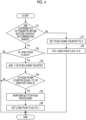
- Fig. 4 is a flowchart related to an operation determination of an operation unit.
- Fig. 5 is a schematic diagram schematically showing an example of the operation panel according to Embodiment 1.
- Fig. 6 is a schematic diagram schematically showing an example of the operation panel according to Embodiment 1.
- An operation display system 1 of Embodiment 1 is a system that virtually displays an operation unit to be operated on a virtual space.
- the operation display system 1 is applied to, for example, a training system for performing various types of training, and an operation target is, for example, an operation device of an aircraft, a control operation device of a plant, an operation device of a vehicle, or the like.
- the operation display system 1 will be described as being applied to the operation device of the aircraft.
- the operation unit targets, for example, a component for performing a push-down operation, and includes, for example, an operation button, a changeover switch, and the like.
- the operation display system 1 includes an operation panel 10, first and second hand trackers (finger detection sensors) 11 and 12, a display unit 14, and a control unit 15. Since the display unit 14 and the second hand tracker 12 are integrally incorporated in a head mounted display (HMD) 21, the operation display system 1 has a configuration including the operation panel 10, the first hand tracker 11, the HMD 21, and the control unit 15.
- HMD head mounted display
- the HMD 21 has the display unit 14 that is set on the head of the operator and that is disposed in front of the operator's eyes, and the second hand tracker 12 that detects the finger of the operator.
- the display unit 14 is, for example, a display as a display device.
- the display unit 14 displays an image generated in the control unit 15.
- the display unit 14 displays, as an image, for example, an image G of the cockpit of the aircraft as the virtual space shown in Fig. 3 , and the image G includes an operation device P as the operation unit provided in the cockpit and a finger H of the pilot.
- the second hand tracker 12 is provided integrally with the HMD 21 and detects the finger of the operator in a predetermined detection range. For this reason, the detection range of the second hand tracker 12 changes according to the movement of the head of the operator.
- the position of the HMD 21 set to the home position is the initial position
- the initial position is the reference position of the three-dimensional coordinates in the virtual space. That is, the registration between the three-dimensional coordinates in the virtual space and the three-dimensional coordinates in the real space is performed based on the reference position.
- the first hand tracker 11 is provided at an installation location where the operation panel 10 is installed, and detects the finger of the operator in a predetermined detection range. For this reason, the first hand tracker 11 has a fixed detection range and detects the finger of the operator around the operation panel 10.
- the operation panel 10 is installed at a position in the real space corresponding to the operation device P in the virtual space.
- the operation panel 10 includes a base 25 and a bodily sensation imparting member 26 disposed on the base 25.
- the base 25 is a plate-shaped member.
- the bodily sensation imparting member 26 is a member that imparts a bodily sensation to the operator, and is a member that imparts a bodily sensation related to the button operation of the operation device P.
- the bodily sensation imparting member 26 is a foam 26a such as a sponge, and is elastically deformed by the operator performing the push-down operation, thereby imparting the bodily sensation of the push-down operation to the operator.
- the bodily sensation imparting member 26 is not particularly limited to the foam, and for example, a gel-like material, cloth, or the like may be applied, and any member may be used as long as the member imparts the bodily sensation to the operator.
- the disposition region where the operation panel 10 is disposed is a region larger than the operation region where the operation device P is operated. Specifically, the operation panel 10 has a size that allows a positional deviation between the operation device P in the virtual space and the operation panel 10 in the real space. For this reason, the operation panel 10 has a region larger than the surface of the operation device P, and the thickness of the operation panel 10 is larger than the operation amount (pushing down) of the operation button in the operation device P.
- the control unit 15 includes, for example, an integrated circuit such as a central processing unit (CPU).
- the control unit 15 simulates the operation of the aircraft based on the input of the operation device P operated in the virtual space, performs display control of the HMD 21, or combines the positions of the finger detected by the first hand tracker 11 and the second hand tracker 12.
- control unit 15 executes processing of simulating the operation of the aircraft, operates the aircraft in a simulated manner based on the input of the operation device P operated in the virtual space, and displays a result of the operation on the display unit 14 as the image G.
- control unit 15 acquires the position-combined position (coordinates) of the finger by performing position combination using the position combination program based on the positions of the finger detected by the first hand tracker 11 and the second hand tracker 12.
- the control unit 15 generates an image of the finger based on the acquired position of the finger, superimposes the generated image of the finger on the image G, and displays the image G on the display unit 14.
- Fig. 4 the processing is the operation determination processing in a case where a predetermined operation button in the operation device P is operated.
- the operation determination processing shown in Fig. 4 is repeatedly executed in the control unit 15.
- the control unit 15 determines whether or not the acquired position (coordinates) of the fingertip is within a button contact determination range with which a predetermined operation button of the operation device P comes into contact, in the virtual space (step S1).
- the control unit 15 determines in step S1 that the position of the fingertip is within the button contact determination range (step S1: Yes)
- the control unit 15 determines whether or not a long push flag, which is a flag that the button operation is being long pushed, is 0 (not long pushed) (step S2).
- step S3 the control unit 15 adds +1 in the push-down counter of the push-down operation.
- step S4 the control unit 15 determines whether or not the push-down counter is equal to or greater than a preset counter value X (step S4).
- step S5 the control unit 15 executes button push processing on the assumption that the operation button is pushed down by being present in the button contact determination range for a predetermined time (step S5).
- step S6 the control unit 15 sets the long push flag to 1 (long pushed) (step S6), and then ends the operation determination processing.
- step S1 in a case where the control unit 15 determines that the position of the fingertip is not within the button contact determination range (step S1: No), the control unit 15 resets the push-down counter to 0 (step S7). In addition, after executing step S7, the control unit 15 resets the long push flag to 0 (step S8) and ends the operation determination processing.
- step S2 determines that the long push flag is not 0 in step S2 (step S2: No)
- the control unit 15 assumes that the button operation is being long pushed, that is, the button operation is continuously performed, and ends the operation determination processing.
- step S4 determines in step S4 that the push-down counter is not equal to or greater than the counter value X (step S4: No)
- the control unit 15 ends the operation determination processing on the assumption that the button operation is not continuously performed for a predetermined time.
- a switch 26b is disposed as the bodily sensation imparting member 26 instead of the foam 26a of the operation panel 10 shown in Fig. 2 .
- the switch 26b is a button that can be turned on/off (ON/OFF) by the push-down operation.
- a plurality of the switches 26b may be disposed to correspond to the operation buttons of the operation device P, or the plurality of the switches 26b may be disposed in a spread state.
- the switch 26b is disposed between the base 25 and the foam 26a.
- the switch 26b is the same as the switch 26b shown in Fig. 5 .
- FIG. 7 is a block diagram showing an example of an operation display system according to Embodiment 2.
- the switch 26b is connected to the control unit 15 in the operation panel 10 including the switch 26b shown in Fig. 5 or Fig. 6 .
- the control unit 15 is capable of acquiring whether or not the turn-on/off operation of the switch 26b is operable, and executes the operation determination processing based on whether or not the switch 26b is operable. That is, when the switch 26b is pushed down, the control unit 15 executes the button push processing.
- the control unit 15 may perform the operation determination processing of Embodiment 2 in parallel with the operation determination processing of Embodiment 1, or may omit the operation determination processing of Embodiment 1.
- the bodily sensation imparting member 26 of the operation panel 10 may further include a changeover mechanism that changes over whether or not the turn-on/off operation of the switch 26b is operable.
- the control unit 15 is connected to the changeover mechanism, and executes changeover control to disable the turn-on/off operation of the switch 26b or to enable the turn-on/off operation of the switch 26b by controlling the changeover mechanism.
- the control unit 15 causes the switch 26b corresponding to the operation button to be operable and causes the switch 26b not corresponding to the operation button to be inoperable according to the type of the operation device P to be operated. Accordingly, the control unit 15 can make the operation panel 10 correspond to various operation devices P.
- a configuration in which the input operation of the switch 26b is disabled includes, for example, a configuration in which a physical push-down operation of the switch 26b is possible but an input signal by the push-down operation is not input to the control unit 15, and a configuration in which the switch 26b cannot be physically pushed down. With these configurations, it is possible to cause the operation panel 10 to correspond to an operation device having various operation ranges.
- the switch 26b cannot be physically pushed down, even when the pilot performs the push-down operation on the operation panel 10 at a position where the operation button in the virtual space is not present, the switch 26b is inoperable. Therefore, the bodily sensation of the push-down operation is not imparted to the pilot, and thus, a more accurate bodily sensation is imparted.
- Embodiments 1 and 2 are understood as follows, for example.
- An operation display system 1, 50 is an operation display system 1, 50 that virtually displays an operation unit (operation device P) to be operated on a virtual space
- the operation display system 1, 50 including: an operation panel 10; a finger detection sensor 11, 12 that detects a position of a finger of an operator who operates the operation panel; a display unit 14 that superimposes and displays the operation unit corresponding to a position of the operation panel 10 and an image indicating the position of the finger on the virtual space, based on the detected position of the finger with respect to the operation panel 10; and a control unit 15 that executes display control relating to display of the operation unit and the image indicating the position of the finger on the display unit 14, in which the operation panel 10 has a base 25, and a bodily sensation imparting member 26 that is disposed on the base 25 and imparts a bodily sensation to the operator, and the control unit 15 determines whether or not there is an operation of the operation unit, based on a detection result of the finger detection sensor 11, 12.
- the bodily sensation imparting member 26 can impart an operational feeling to the operator, and thus, the operator can obtain the same operability as in a real space even in a virtual space.
- the bodily sensation imparting member 26 includes at least one of a foam 26a that is elastically deformed in accordance with a push-down operation and a switch 26b that is turned on/off in accordance with the push-down operation.
- the foam 26a and the switch 26b can impart the bodily sensation of the push-down operation to the operator.
- the bodily sensation imparting member 26 can absorb the positional deviation between the operation unit in the virtual space and the operation panel in the real space.
- the control unit 15 determines that there is the operation of the operation unit in a case where the finger of the operator is present in an operation unit contact determination range corresponding to the operation unit on the bodily sensation imparting member 26 for a predetermined time, from the detection result of the finger detection sensor 11, 12.
- the display unit 14 is included in a head mounted display 21, and the finger detection sensor 11, 12 includes a first finger detection sensor 11 provided at an installation location of the operation panel 10, and a second finger detection sensor 12 provided in the head mounted display 21.
- the first finger detection sensor 11 and the second finger detection sensor 12 can widen the detection range of the finger of the operator, and thus the finger of the operator can be accurately detected.
- the bodily sensation imparting member 26 includes a switch 26b that is turned on/off in accordance with a push-down operation, and a changeover mechanism that changes over whether or not a turn-on/off operation of the switch 26b is operable, and the control unit 15 causes the turn-on/off operation of the switch 26b corresponding to an inoperable region of the operation unit to be inoperable via the changeover mechanism, and causes the turn-on/off operation of the switch 26b corresponding to an operable region of the operation unit to be operable via the changeover mechanism.
Landscapes
- Engineering & Computer Science (AREA)
- Theoretical Computer Science (AREA)
- General Engineering & Computer Science (AREA)
- General Physics & Mathematics (AREA)
- Physics & Mathematics (AREA)
- Human Computer Interaction (AREA)
- Mechanical Engineering (AREA)
- Chemical & Material Sciences (AREA)
- Transportation (AREA)
- Combustion & Propulsion (AREA)
- Aviation & Aerospace Engineering (AREA)
- Business, Economics & Management (AREA)
- Educational Administration (AREA)
- Educational Technology (AREA)
- Multimedia (AREA)
- Position Input By Displaying (AREA)
- Processing Or Creating Images (AREA)
- User Interface Of Digital Computer (AREA)
Abstract
Description
- The present disclosure relates to an operation display system.
- In the related art, a system that displays a digital object on a device is known (for example, refer to PTL 1).
- [PTL 1]
Japanese Unexamined Patent Application Publication No. 2022-34560 - As a system as in PTL 1, for example, there is a system that displays an operation device as a digital object in a virtual space on a head mounted display (HMD). In such a system, when an operator operates the operation device in the virtual space, since there is no operation device in a real space, it is difficult for the operator to obtain an operational feeling of the operation device. In addition, a position of the operation device displayed in the virtual space and a position of a finger of the operator in the real space may deviate from each other, and thus, an operation may be performed in a manner different from an operator's intention.
- Therefore, an object of the present disclosure is to provide an operation display system that imparts an operational feeling to an operator and that enables the operator to obtain the same operability as in a real space even in a virtual space. Solution to Problem
- An operation display system of the present disclosure is an operation display system that virtually displays an operation unit to be operated on a virtual space, the operation display system including: an operation panel; a finger detection sensor that detects a position of a finger of an operator who operates the operation panel; a display unit that superimposes and displays the operation unit corresponding to a position of the operation panel and an image indicating the position of the finger on the virtual space, based on the detected position of the finger with respect to the operation panel; and a control unit that executes display control relating to display of the operation unit and the image indicating the position of the finger on the display unit, in which the operation panel has a base, and a bodily sensation imparting member that is disposed on the base and imparts a bodily sensation to the operator, and the control unit determines whether or not there is an operation of the operation unit, based on a detection result of the finger detection sensor.
- According to the present disclosure, an operational feeling is imparted to an operator and the operator can obtain the same operability as in a real space even in a virtual space.
-
-
Fig. 1 is a block diagram showing an example of an operation display system according to Embodiment 1. -
Fig. 2 is a schematic diagram schematically showing an example of an operation panel according to Embodiment 1. -
Fig. 3 is an explanatory diagram of an operation device that is displayed on a display unit. -
Fig. 4 is a flowchart related to an operation determination of an operation unit. -
Fig. 5 is a schematic diagram schematically showing an example of the operation panel according to Embodiment 1. -
Fig. 6 is a schematic diagram schematically showing an example of the operation panel according to Embodiment 1. -
Fig. 7 is a block diagram showing an example of an operation display system according to Embodiment 2. - Hereinafter, an embodiment according to the present disclosure will be described in detail with reference to the drawings. Further, the present disclosure is not limited by this embodiment. In addition, components in the embodiments described below include those that can be easily replaced by those skilled in the art, or those that are substantially the same. Further, the components described below can be combined as appropriate. Furthermore, in a case where there are a plurality of embodiments, the embodiments can be combined.
-
Fig. 1 is a block diagram showing an example of an operation display system according to Embodiment 1.Fig. 2 is a schematic diagram schematically showing an example of an operation panel according to Embodiment 1.Fig. 3 is an explanatory diagram of an operation device that is displayed on a display unit.Fig. 4 is a flowchart related to an operation determination of an operation unit.Fig. 5 is a schematic diagram schematically showing an example of the operation panel according to Embodiment 1.Fig. 6 is a schematic diagram schematically showing an example of the operation panel according to Embodiment 1. - An operation display system 1 of Embodiment 1 is a system that virtually displays an operation unit to be operated on a virtual space. The operation display system 1 is applied to, for example, a training system for performing various types of training, and an operation target is, for example, an operation device of an aircraft, a control operation device of a plant, an operation device of a vehicle, or the like. In Embodiment 1, the operation display system 1 will be described as being applied to the operation device of the aircraft. In addition, the operation unit targets, for example, a component for performing a push-down operation, and includes, for example, an operation button, a changeover switch, and the like.
- The operation display system 1 includes an
operation panel 10, first and second hand trackers (finger detection sensors) 11 and 12, adisplay unit 14, and acontrol unit 15. Since thedisplay unit 14 and thesecond hand tracker 12 are integrally incorporated in a head mounted display (HMD) 21, the operation display system 1 has a configuration including theoperation panel 10, the first hand tracker 11, the HMD 21, and thecontrol unit 15. - The HMD 21 has the
display unit 14 that is set on the head of the operator and that is disposed in front of the operator's eyes, and thesecond hand tracker 12 that detects the finger of the operator. Thedisplay unit 14 is, for example, a display as a display device. Thedisplay unit 14 displays an image generated in thecontrol unit 15. Thedisplay unit 14 displays, as an image, for example, an image G of the cockpit of the aircraft as the virtual space shown inFig. 3 , and the image G includes an operation device P as the operation unit provided in the cockpit and a finger H of the pilot. - The
second hand tracker 12 is provided integrally with theHMD 21 and detects the finger of the operator in a predetermined detection range. For this reason, the detection range of thesecond hand tracker 12 changes according to the movement of the head of the operator. - In addition, the position of the
HMD 21 set to the home position is the initial position, and the initial position is the reference position of the three-dimensional coordinates in the virtual space. That is, the registration between the three-dimensional coordinates in the virtual space and the three-dimensional coordinates in the real space is performed based on the reference position. - The first hand tracker 11 is provided at an installation location where the
operation panel 10 is installed, and detects the finger of the operator in a predetermined detection range. For this reason, the first hand tracker 11 has a fixed detection range and detects the finger of the operator around theoperation panel 10. - The
operation panel 10 is installed at a position in the real space corresponding to the operation device P in the virtual space. As shown inFig. 2 , theoperation panel 10 includes abase 25 and a bodilysensation imparting member 26 disposed on thebase 25. Thebase 25 is a plate-shaped member. The bodilysensation imparting member 26 is a member that imparts a bodily sensation to the operator, and is a member that imparts a bodily sensation related to the button operation of the operation device P. Specifically, the bodilysensation imparting member 26 is afoam 26a such as a sponge, and is elastically deformed by the operator performing the push-down operation, thereby imparting the bodily sensation of the push-down operation to the operator. The bodilysensation imparting member 26 is not particularly limited to the foam, and for example, a gel-like material, cloth, or the like may be applied, and any member may be used as long as the member imparts the bodily sensation to the operator. The disposition region where theoperation panel 10 is disposed is a region larger than the operation region where the operation device P is operated. Specifically, theoperation panel 10 has a size that allows a positional deviation between the operation device P in the virtual space and theoperation panel 10 in the real space. For this reason, theoperation panel 10 has a region larger than the surface of the operation device P, and the thickness of theoperation panel 10 is larger than the operation amount (pushing down) of the operation button in the operation device P. - The
control unit 15 includes, for example, an integrated circuit such as a central processing unit (CPU). Thecontrol unit 15 simulates the operation of the aircraft based on the input of the operation device P operated in the virtual space, performs display control of theHMD 21, or combines the positions of the finger detected by the first hand tracker 11 and thesecond hand tracker 12. - Specifically, the
control unit 15 executes processing of simulating the operation of the aircraft, operates the aircraft in a simulated manner based on the input of the operation device P operated in the virtual space, and displays a result of the operation on thedisplay unit 14 as the image G. In addition, thecontrol unit 15 acquires the position-combined position (coordinates) of the finger by performing position combination using the position combination program based on the positions of the finger detected by the first hand tracker 11 and thesecond hand tracker 12. Thecontrol unit 15 generates an image of the finger based on the acquired position of the finger, superimposes the generated image of the finger on the image G, and displays the image G on thedisplay unit 14. - Next, the processing related to the operation determination of the operation device P will be described with reference to
Fig. 4 . InFig. 4 , the processing is the operation determination processing in a case where a predetermined operation button in the operation device P is operated. The operation determination processing shown inFig. 4 is repeatedly executed in thecontrol unit 15. - The
control unit 15 determines whether or not the acquired position (coordinates) of the fingertip is within a button contact determination range with which a predetermined operation button of the operation device P comes into contact, in the virtual space (step S1). When thecontrol unit 15 determines in step S1 that the position of the fingertip is within the button contact determination range (step S1: Yes), thecontrol unit 15 determines whether or not a long push flag, which is a flag that the button operation is being long pushed, is 0 (not long pushed) (step S2). - Subsequently, when the
control unit 15 determines that the long push flag is 0 in step S2 (step S2: Yes), thecontrol unit 15 adds +1 in the push-down counter of the push-down operation (step S3). After executing step S3, thecontrol unit 15 determines whether or not the push-down counter is equal to or greater than a preset counter value X (step S4). When thecontrol unit 15 determines in step S4 that the push-down counter is equal to or greater than the counter value X (step S4: Yes), thecontrol unit 15 executes button push processing on the assumption that the operation button is pushed down by being present in the button contact determination range for a predetermined time (step S5). After executing step S5, thecontrol unit 15 sets the long push flag to 1 (long pushed) (step S6), and then ends the operation determination processing. - In step S1, in a case where the
control unit 15 determines that the position of the fingertip is not within the button contact determination range (step S1: No), thecontrol unit 15 resets the push-down counter to 0 (step S7). In addition, after executing step S7, thecontrol unit 15 resets the long push flag to 0 (step S8) and ends the operation determination processing. - When the
control unit 15 determines that the long push flag is not 0 in step S2 (step S2: No), thecontrol unit 15 assumes that the button operation is being long pushed, that is, the button operation is continuously performed, and ends the operation determination processing. - When the
control unit 15 determines in step S4 that the push-down counter is not equal to or greater than the counter value X (step S4: No), thecontrol unit 15 ends the operation determination processing on the assumption that the button operation is not continuously performed for a predetermined time. - Next, other examples of the
operation panel 10 will be described with reference toFigs. 5 and 6 . In theoperation panel 10 shown inFig. 5 , aswitch 26b is disposed as the bodilysensation imparting member 26 instead of thefoam 26a of theoperation panel 10 shown inFig. 2 . Theswitch 26b is a button that can be turned on/off (ON/OFF) by the push-down operation. A plurality of theswitches 26b may be disposed to correspond to the operation buttons of the operation device P, or the plurality of theswitches 26b may be disposed in a spread state. - In the
operation panel 10 shown inFig. 6 , as the bodilysensation imparting member 26, in addition to thefoam 26a of theoperation panel 10 shown inFig. 2 , theswitch 26b is disposed between the base 25 and thefoam 26a. Theswitch 26b is the same as theswitch 26b shown inFig. 5 . - Next, Embodiment 2 will be described with reference to
Fig. 7 . Note that, in Embodiment 2, in order to avoid duplicate descriptions, portions that are different from those of Embodiment 1 will be described, and portions having the same configuration as those of Embodiment 1 will be described with the same reference numerals.Fig. 7 is a block diagram showing an example of an operation display system according to Embodiment 2. - In an
operation display system 50 of Embodiment 2, theswitch 26b is connected to thecontrol unit 15 in theoperation panel 10 including theswitch 26b shown inFig. 5 or Fig. 6 . Thecontrol unit 15 is capable of acquiring whether or not the turn-on/off operation of theswitch 26b is operable, and executes the operation determination processing based on whether or not theswitch 26b is operable. That is, when theswitch 26b is pushed down, thecontrol unit 15 executes the button push processing. Thecontrol unit 15 may perform the operation determination processing of Embodiment 2 in parallel with the operation determination processing of Embodiment 1, or may omit the operation determination processing of Embodiment 1. - In addition, in Embodiment 2, the bodily
sensation imparting member 26 of theoperation panel 10 may further include a changeover mechanism that changes over whether or not the turn-on/off operation of theswitch 26b is operable. Thecontrol unit 15 is connected to the changeover mechanism, and executes changeover control to disable the turn-on/off operation of theswitch 26b or to enable the turn-on/off operation of theswitch 26b by controlling the changeover mechanism. - The
control unit 15 causes theswitch 26b corresponding to the operation button to be operable and causes theswitch 26b not corresponding to the operation button to be inoperable according to the type of the operation device P to be operated. Accordingly, thecontrol unit 15 can make theoperation panel 10 correspond to various operation devices P. A configuration in which the input operation of theswitch 26b is disabled includes, for example, a configuration in which a physical push-down operation of theswitch 26b is possible but an input signal by the push-down operation is not input to thecontrol unit 15, and a configuration in which theswitch 26b cannot be physically pushed down. With these configurations, it is possible to cause theoperation panel 10 to correspond to an operation device having various operation ranges. Further, with the configuration in which theswitch 26b cannot be physically pushed down, even when the pilot performs the push-down operation on theoperation panel 10 at a position where the operation button in the virtual space is not present, theswitch 26b is inoperable. Therefore, the bodily sensation of the push-down operation is not imparted to the pilot, and thus, a more accurate bodily sensation is imparted. - As described above, the
operation display systems 1 and 50 described in Embodiments 1 and 2 are understood as follows, for example. - An
operation display system 1, 50 according to a first aspect is anoperation display system 1, 50 that virtually displays an operation unit (operation device P) to be operated on a virtual space, theoperation display system 1, 50 including: anoperation panel 10; afinger detection sensor 11, 12 that detects a position of a finger of an operator who operates the operation panel; adisplay unit 14 that superimposes and displays the operation unit corresponding to a position of theoperation panel 10 and an image indicating the position of the finger on the virtual space, based on the detected position of the finger with respect to theoperation panel 10; and acontrol unit 15 that executes display control relating to display of the operation unit and the image indicating the position of the finger on thedisplay unit 14, in which theoperation panel 10 has abase 25, and a bodilysensation imparting member 26 that is disposed on thebase 25 and imparts a bodily sensation to the operator, and thecontrol unit 15 determines whether or not there is an operation of the operation unit, based on a detection result of thefinger detection sensor 11, 12. - With this configuration, the bodily
sensation imparting member 26 can impart an operational feeling to the operator, and thus, the operator can obtain the same operability as in a real space even in a virtual space. - As a second aspect, in the
operation display system 1, 50 according to the first aspect, the bodilysensation imparting member 26 includes at least one of afoam 26a that is elastically deformed in accordance with a push-down operation and aswitch 26b that is turned on/off in accordance with the push-down operation. - With this configuration, the
foam 26a and theswitch 26b can impart the bodily sensation of the push-down operation to the operator. - As a third aspect, in the
operation display system 1, 50 according to the first or second aspect, a disposition region in which the bodilysensation imparting member 26 is disposed is a region larger than an operation region in which the operation unit is operated. - With this configuration, the bodily
sensation imparting member 26 can absorb the positional deviation between the operation unit in the virtual space and the operation panel in the real space. - As a fourth aspect, in the
operation display system 1, 50 according to any one of the first to third aspects, thecontrol unit 15 determines that there is the operation of the operation unit in a case where the finger of the operator is present in an operation unit contact determination range corresponding to the operation unit on the bodilysensation imparting member 26 for a predetermined time, from the detection result of thefinger detection sensor 11, 12. - With this configuration, it is possible to suitably detect whether or not there is an operation by the operator.
- As a fifth aspect, in the
operation display system 1, 50 according to any one of the first to fourth aspects, thedisplay unit 14 is included in a head mounteddisplay 21, and thefinger detection sensor 11, 12 includes a first finger detection sensor 11 provided at an installation location of theoperation panel 10, and a secondfinger detection sensor 12 provided in the head mounteddisplay 21. - With this configuration, the first finger detection sensor 11 and the second
finger detection sensor 12 can widen the detection range of the finger of the operator, and thus the finger of the operator can be accurately detected. - As a sixth aspect, in the
operation display system 50 according to any one of the first to fifth aspects, the bodilysensation imparting member 26 includes aswitch 26b that is turned on/off in accordance with a push-down operation, and a changeover mechanism that changes over whether or not a turn-on/off operation of theswitch 26b is operable, and thecontrol unit 15 causes the turn-on/off operation of theswitch 26b corresponding to an inoperable region of the operation unit to be inoperable via the changeover mechanism, and causes the turn-on/off operation of theswitch 26b corresponding to an operable region of the operation unit to be operable via the changeover mechanism. - With this configuration, it is possible to cause the
operation panel 10 to correspond to various operation units by changing over whether or not the turn-on/off operation of theswitch 26b is operable according to the type of the operation unit to be operated. -
- 1: operation display system
- 10: operation panel
- 11: first hand tracker
- 12: second hand tracker
- 14: display unit
- 15: control unit
- 21: HMD
- 25: base
- 26: bodily sensation imparting member
- 26a: foam
- 26b: switch
- 50: operation display system
Claims (6)
- An operation display system that virtually displays an operation unit to be operated on a virtual space, the operation display system comprising:an operation panel;a finger detection sensor that detects a position of a finger of an operator who operates the operation panel;a display unit that superimposes and displays the operation unit corresponding to a position of the operation panel and an image indicating the position of the finger on the virtual space, based on the detected position of the finger with respect to the operation panel; anda control unit that executes display control relating to display of the operation unit and the image indicating the position of the finger on the display unit,wherein the operation panel hasa base, anda bodily sensation imparting member that is disposed on the base and imparts a bodily sensation to the operator, andthe control unit determines whether or not there is an operation of the operation unit, based on a detection result of the finger detection sensor.
- The operation display system according to Claim 1,
wherein the bodily sensation imparting member includes at least one of a foam that is elastically deformed in accordance with a push-down operation and a switch that is turned on/off in accordance with the push-down operation. - The operation display system according to Claim 1,
wherein a disposition region in which the bodily sensation imparting member is disposed is a region larger than an operation region in which the operation unit is operated. - The operation display system according to Claim 1,
wherein the control unit determines that there is the operation of the operation unit in a case where the finger of the operator is present in an operation unit contact determination range corresponding to the operation unit on the bodily sensation imparting member for a predetermined time, from the detection result of the finger detection sensor. - The operation display system according to Claim 1,wherein the display unit is included in a head mounted display, andthe finger detection sensor includesa first finger detection sensor provided at an installation location of the operation panel, anda second finger detection sensor provided in the head mounted display.
- The operation display system according to Claim 1,wherein the bodily sensation imparting member includesa switch that is turned on/off in accordance with a push-down operation, anda changeover mechanism that changes over whether or not a turn-on/off operation of the switch is operable, andthe control unit causes the turn-on/off operation of the switch corresponding to an inoperable region of the operation unit to be inoperable via the changeover mechanism, and causes the turn-on/off operation of the switch corresponding to an operable region of the operation unit to be operable via the changeover mechanism.
Applications Claiming Priority (2)
| Application Number | Priority Date | Filing Date | Title |
|---|---|---|---|
| JP2022183620A JP2024072656A (en) | 2022-11-16 | 2022-11-16 | Operation display system |
| PCT/JP2023/041235 WO2024106500A1 (en) | 2022-11-16 | 2023-11-16 | Operation display system |
Publications (2)
| Publication Number | Publication Date |
|---|---|
| EP4553623A1 true EP4553623A1 (en) | 2025-05-14 |
| EP4553623A4 EP4553623A4 (en) | 2025-11-26 |
Family
ID=91084477
Family Applications (1)
| Application Number | Title | Priority Date | Filing Date |
|---|---|---|---|
| EP23891647.2A Pending EP4553623A4 (en) | 2022-11-16 | 2023-11-16 | OPERATING DISPLAY SYSTEM |
Country Status (3)
| Country | Link |
|---|---|
| EP (1) | EP4553623A4 (en) |
| JP (1) | JP2024072656A (en) |
| WO (1) | WO2024106500A1 (en) |
Family Cites Families (5)
| Publication number | Priority date | Publication date | Assignee | Title |
|---|---|---|---|---|
| US10852838B2 (en) * | 2014-06-14 | 2020-12-01 | Magic Leap, Inc. | Methods and systems for creating virtual and augmented reality |
| JP2016184244A (en) * | 2015-03-25 | 2016-10-20 | 三菱重工業株式会社 | Simulator device and image formation method |
| US11688297B2 (en) * | 2018-11-19 | 2023-06-27 | The Boeing Company | Virtual reality with virtualization in trainers and test environments |
| CN114127667A (en) * | 2019-07-18 | 2022-03-01 | 索尼集团公司 | Shape variable device, shape control method, and tactile sensation presentation apparatus |
| US12322131B2 (en) | 2020-08-18 | 2025-06-03 | Unity IPR ApS | Method and system for displaying a large 3D model on a remote device |
-
2022
- 2022-11-16 JP JP2022183620A patent/JP2024072656A/en active Pending
-
2023
- 2023-11-16 EP EP23891647.2A patent/EP4553623A4/en active Pending
- 2023-11-16 WO PCT/JP2023/041235 patent/WO2024106500A1/en not_active Ceased
Also Published As
| Publication number | Publication date |
|---|---|
| WO2024106500A1 (en) | 2024-05-23 |
| JP2024072656A (en) | 2024-05-28 |
| EP4553623A4 (en) | 2025-11-26 |
Similar Documents
| Publication | Publication Date | Title |
|---|---|---|
| JP4523346B2 (en) | Display system | |
| US9372538B2 (en) | Multiple-force, dynamically-adjusted, 3-D touch surface with feedback for human machine interface (HMI) | |
| US20210055790A1 (en) | Information processing apparatus, information processing system, information processing method, and recording medium | |
| US20170025031A1 (en) | Method and apparatus for testing a device for use in an aircraft | |
| JP2004070920A (en) | Information processing program, computer readable recording medium recording information processing program, information processing method and information processor | |
| EP2741171A1 (en) | Method, human-machine interface and vehicle | |
| CN108108042B (en) | Display device for vehicle and control method thereof | |
| GB2509651A (en) | Object designation method, device and computer program | |
| CN109643219A (en) | Method for being interacted with the picture material presented in display equipment in the car | |
| WO2010033522A2 (en) | Integrated haptic control apparatus and touch sensitive display | |
| US11132089B2 (en) | Input device | |
| US10180756B2 (en) | Input apparatus | |
| US12148322B2 (en) | Head tracking with virtual avionics training products | |
| US10558310B2 (en) | Onboard operation apparatus | |
| Ohshima et al. | A mixed reality system with visual and tangible interaction capability: Application to evaluating automobile interior design | |
| US9971494B2 (en) | Touch switch module | |
| US20190250776A1 (en) | Vehicular display apparatus | |
| EP3421300B1 (en) | Control unit for vehicle | |
| Dodd et al. | Touch on the flight deck: The impact of display location, size, touch technology & turbulence on pilot performance | |
| EP3971870B1 (en) | Advanced haptics in touchscreen avionics lower level device simulators | |
| US20150130718A1 (en) | Information processor | |
| JP2024072656A (en) | Operation display system | |
| JP2011134258A (en) | Input device and input control device including the same | |
| US10963048B2 (en) | Method and a system for visual human-machine interaction | |
| CN107407966A (en) | Method for the motor vehicle simulation device of virtual environment of the simulation with virtual motor vehicle and for simulating virtual environment |
Legal Events
| Date | Code | Title | Description |
|---|---|---|---|
| STAA | Information on the status of an ep patent application or granted ep patent |
Free format text: STATUS: THE INTERNATIONAL PUBLICATION HAS BEEN MADE |
|
| PUAI | Public reference made under article 153(3) epc to a published international application that has entered the european phase |
Free format text: ORIGINAL CODE: 0009012 |
|
| STAA | Information on the status of an ep patent application or granted ep patent |
Free format text: STATUS: REQUEST FOR EXAMINATION WAS MADE |
|
| 17P | Request for examination filed |
Effective date: 20250207 |
|
| AK | Designated contracting states |
Kind code of ref document: A1 Designated state(s): AL AT BE BG CH CY CZ DE DK EE ES FI FR GB GR HR HU IE IS IT LI LT LU LV MC ME MK MT NL NO PL PT RO RS SE SI SK SM TR |
|
| A4 | Supplementary search report drawn up and despatched |
Effective date: 20251027 |
|
| RIC1 | Information provided on ipc code assigned before grant |
Ipc: G06F 3/0354 20130101AFI20251021BHEP Ipc: G06F 3/01 20060101ALI20251021BHEP Ipc: G06T 19/00 20110101ALI20251021BHEP Ipc: B60K 35/00 20240101ALI20251021BHEP Ipc: B60K 35/10 20240101ALI20251021BHEP Ipc: G06F 3/03 20060101ALI20251021BHEP Ipc: G09B 9/08 20060101ALI20251021BHEP Ipc: G09B 9/28 20060101ALI20251021BHEP |
|
| DAV | Request for validation of the european patent (deleted) | ||
| DAX | Request for extension of the european patent (deleted) |