EP4553611A1 - Electronic device - Google Patents
Electronic device Download PDFInfo
- Publication number
- EP4553611A1 EP4553611A1 EP24192609.6A EP24192609A EP4553611A1 EP 4553611 A1 EP4553611 A1 EP 4553611A1 EP 24192609 A EP24192609 A EP 24192609A EP 4553611 A1 EP4553611 A1 EP 4553611A1
- Authority
- EP
- European Patent Office
- Prior art keywords
- housing
- pushing member
- electronic device
- limiting member
- module
- Prior art date
- Legal status (The legal status is an assumption and is not a legal conclusion. Google has not performed a legal analysis and makes no representation as to the accuracy of the status listed.)
- Pending
Links
Images







Classifications
-
- G—PHYSICS
- G06—COMPUTING OR CALCULATING; COUNTING
- G06F—ELECTRIC DIGITAL DATA PROCESSING
- G06F1/00—Details not covered by groups G06F3/00 - G06F13/00 and G06F21/00
- G06F1/16—Constructional details or arrangements
- G06F1/1613—Constructional details or arrangements for portable computers
- G06F1/1633—Constructional details or arrangements of portable computers not specific to the type of enclosures covered by groups G06F1/1615 - G06F1/1626
- G06F1/1635—Details related to the integration of battery packs and other power supplies such as fuel cells or integrated AC adapter
-
- G—PHYSICS
- G06—COMPUTING OR CALCULATING; COUNTING
- G06F—ELECTRIC DIGITAL DATA PROCESSING
- G06F1/00—Details not covered by groups G06F3/00 - G06F13/00 and G06F21/00
- G06F1/16—Constructional details or arrangements
- G06F1/1613—Constructional details or arrangements for portable computers
- G06F1/1633—Constructional details or arrangements of portable computers not specific to the type of enclosures covered by groups G06F1/1615 - G06F1/1626
- G06F1/1675—Miscellaneous details related to the relative movement between the different enclosures or enclosure parts
- G06F1/1679—Miscellaneous details related to the relative movement between the different enclosures or enclosure parts for locking or maintaining the movable parts of the enclosure in a fixed position, e.g. latching mechanism at the edge of the display in a laptop or for the screen protective cover of a PDA
-
- G—PHYSICS
- G06—COMPUTING OR CALCULATING; COUNTING
- G06F—ELECTRIC DIGITAL DATA PROCESSING
- G06F1/00—Details not covered by groups G06F3/00 - G06F13/00 and G06F21/00
- G06F1/16—Constructional details or arrangements
- G06F1/1613—Constructional details or arrangements for portable computers
- G06F1/1633—Constructional details or arrangements of portable computers not specific to the type of enclosures covered by groups G06F1/1615 - G06F1/1626
- G06F1/1656—Details related to functional adaptations of the enclosure, e.g. to provide protection against EMI, shock, water, or to host detachable peripherals like a mouse or removable expansions units like PCMCIA cards, or to provide access to internal components for maintenance or to removable storage supports like CDs or DVDs, or to mechanically mount accessories
- G06F1/1658—Details related to functional adaptations of the enclosure, e.g. to provide protection against EMI, shock, water, or to host detachable peripherals like a mouse or removable expansions units like PCMCIA cards, or to provide access to internal components for maintenance or to removable storage supports like CDs or DVDs, or to mechanically mount accessories related to the mounting of internal components, e.g. disc drive or any other functional module
-
- G—PHYSICS
- G06—COMPUTING OR CALCULATING; COUNTING
- G06F—ELECTRIC DIGITAL DATA PROCESSING
- G06F1/00—Details not covered by groups G06F3/00 - G06F13/00 and G06F21/00
- G06F1/16—Constructional details or arrangements
- G06F1/18—Packaging or power distribution
- G06F1/183—Internal mounting support structures, e.g. for supporting printed circuit boards
- G06F1/187—Mounting of fixed or removable disk drives
-
- G—PHYSICS
- G06—COMPUTING OR CALCULATING; COUNTING
- G06F—ELECTRIC DIGITAL DATA PROCESSING
- G06F1/00—Details not covered by groups G06F3/00 - G06F13/00 and G06F21/00
- G06F1/16—Constructional details or arrangements
- G06F1/18—Packaging or power distribution
- G06F1/183—Internal mounting support structures, e.g. for supporting printed circuit boards
- G06F1/188—Mounting of power supply units
-
- H—ELECTRICITY
- H04—ELECTRIC COMMUNICATION TECHNIQUE
- H04M—TELEPHONIC COMMUNICATION
- H04M1/00—Substation equipment, e.g. for use by subscribers
- H04M1/02—Constructional features of telephone sets
- H04M1/0202—Portable telephone sets, e.g. cordless phones, mobile phones or bar type handsets
- H04M1/026—Details of the structure or mounting of specific components
- H04M1/0262—Details of the structure or mounting of specific components for a battery compartment
Definitions
- the present invention relates to an electronic device, and more particularly to an electronic device having detachable electronic modules.
- detachable electronic modules e.g., batteries and solid-state drives
- a conventional electronic device e.g., a laptop computer
- the detachable electronic modules e.g., batteries and solid-state drives
- the detachable electronic modules may be easily detached from the laptop computer.
- the detachable electronic modules can also easily be intentionally detached from the conventional electronic device. Accordingly, any person with malicious intent can easily detach the detachable electronic modules from the conventional electronic device. In a real-world situation, when the detachable electronic modules are solid-state drives that have confidential information stored therein, the person with malicious intent can easily remove the detachable electronic modules from the conventional electronic device and cause trouble for users thereof.
- the present invention provides an electronic device for improving on the issues associated with conventional electronic devices having detachable electronic modules that easily detach therefrom or are easily stolen by people with malicious intent.
- the electronic device includes a housing, a detachable electronic module, and a switch mechanism.
- the housing includes an accommodating chamber, and the detachable electronic module is detachably assembled to the accommodating chamber of the housing.
- the switch mechanism is disposed on the housing, and the switch mechanism includes a pushing member and a limiting member.
- the pushing member is movable relative to the housing between a locked position and an unlocked position.
- the pushing member When the detachable electronic module is assembled to the accommodating chamber, the pushing member is located at the locked position, and the limiting member is located at a limited position, such that the detachable electronic module is fixed to the housing, and the pushing member is limited by the limiting member and is not movable to the unlocked position.
- the detachable electronic module is assembled in the accommodating chamber and the pushing member and the limiting member are respectively located at the locked position and the limited position, the detachable electronic module is not easily detached from the electronic device.
- FIG. 1 is a schematic perspective view showing a bottom side of an electronic device according to a first embodiment of the present invention
- FIG. 2 is a partial schematic enlarged view of the electronic device in the present embodiment
- FIG. 3 is a partial schematic exploded view of the electronic device in the first embodiment
- FIG. 4 is a schematic exploded view of a housing and a detachable electronic module of the electronic device in the present embodiment
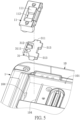
- FIG. 5 is a schematic exploded view of the housing and a pushing member of the electronic device in the present embodiment.
- the electronic device 100 in the present invention includes a housing 1, three detachable electronic modules 2 (e.g., detachable modules 2), and three switch mechanisms 3.
- the detachable modules 2 in this embodiment are detachable electronic modules, but the present invention is not limited thereto.
- Each of the detachable electronic modules 2 is detachably assembled to the housing 1, each of the switch mechanisms 3 is disposed on the housing 1, and each of the switch mechanisms 3 is disposed on one of the detachable electronic modules 2 adjacent thereto.
- Each of the switch mechanisms 3 is configured to provide a manipulation of a user, such that the detachable electronic modules 2 are fixed to the housing 1.
- a quantity of the detachable electronic modules 2 and a quantity of the switch mechanisms 3 provided in the electronic device 100 can be changed according to practical requirements and are not limited by the present embodiment.
- the electronic device 100 can be applied as a laptop computer, a tablet computer, etc., and is particularly suitable for use as a rugged computer.
- the rugged computer is suitable for use by units that need to process sensitive data, such as military units, intelligence units, etc., but is not limited by the present embodiment.
- the electronic device 100 is used as the laptop computer, the electronic device 100 includes a screen, a keyboard, a hard disk drive and other components provided in the laptop computer.
- the housing 1 includes a housing body 10 and three switch shells 11.
- the housing body 10 includes three accommodating chambers 101, and each of the accommodating chambers 101 is configured to accommodate one of the detachable electronic modules 2.
- the housing body 10 is provided to be an outer housing and a main support structure of the electronic device 100, the three switch shells 11 are fixed to the housing body 10, and each of the switch shells 11 is used to shield and limit a movable range of a pushing member 31 of one of the switch mechanisms 3.
- the switch mechanism 3 includes the pushing member 31 and a limiting member 32.
- the pushing member 31 is movable relative to the housing 1 between a locked position and an unlocked position.
- the housing 1 can have guide structures 104 (e.g., various sliding grooves and/or various slide rails), a part of the pushing member 31 is slidably connected to the guide structures 104, and the pushing member 31 is slidable relative the housing 1 through the guide structures 104.
- the limiting member 32 can be a screw, but the present invention is not limited thereto.
- a manipulation hole of the limiting member 32 is not crossed or slotted, and is a specially shaped hole.
- the limiting member 32 cannot be removed directly by using common tools (e.g., a screwdriver-crossed or a screwdriver-slotted).
- the pushing member 31 when the pushing member 31 is located at the locked position, the pushing member 31 is provided to limit and fix the detachable electronic module 2 to the housing 1, such that the user is basically unable to directly pull the detachable electronic module 2 and disassemble the detachable electronic module 2 from the accommodating chamber 101 (as shown in FIG. 4 ).
- the limiting member 32 is located at a limited position, and the pushing member 31 is limited by the limiting member 32, such that the pushing member 31 cannot be manipulated to be moved from the locked position shown in FIG. 2 to the unlocked position shown in FIG. 4 .
- the user cannot disassemble the detachable electronic module 2 from the accommodating chamber 101 with bare hands when the user does not use any tool (e.g., a screwdriver).
- the pushing member 31 is no longer limited by the limiting member 32, and the pushing member 31 can be pushed to the unlocked position shown in FIG. 3 , such that the user can pull the detachable electronic module 2 with their bare hands to disassemble the detachable electronic module 2 from the accommodating chamber 101.
- a tool e.g., a screwdriver
- the housing 1, the switch mechanisms 3, and the detachable electronic modules 2 are provided to be in cooperation with each other, such that the user can fix the detachable electronic modules 2 to the housing 1 according to practical requirements, thereby preventing the detachable electronic modules 2 from being easily disassembled from the housing 1 by people with malicious intent and preventing the detachable electronic modules 2 from being easily detached from the housing 1.
- the confidential information is stored in a solid-state drive (SSD) that can be quickly and detachably assembled to the rugged laptop computer.
- SSD solid-state drive
- the solid-state drive can be disassembled and placed in a specific place for safekeeping. During work hours, the relevant personnel can reassemble the solid-state drive to the rugged laptop computer.
- the solid-state drive can easily be unexpectedly detached from the rugged laptop computer by an external force, causing trouble to the user.
- the solid-state drive when the solid-state drive is assembled on the rugged laptop computer, the solid-state drive can easily be deliberately disassembled from the rugged laptop computer by people with malicious intent.
- the electronic device 100 of the present invention is provided with the switch mechanisms 3, such that the relevant personnel can manipulate the limiting member 32 to be located at the limited position for preventing the pushing member 31 from being manipulated, thereby fixing the detachable electronic modules 2 to the housing 1. Accordingly, the detachable electronic modules 2 can be prevented from being detached from the housing 1, thereby effectively solving the above issues of the conventional rugged laptop computer. Furthermore, in the embodiment in which the limiting member 32 is the screw, the size of the threaded hole and the shape of the operating hole of the limiting member 32 can have a special design, so that if the electronic device 100 is stolen by someone other than the user, the detachable electronic modules 2 still cannot be quickly disassembled from the housing 1 with an appropriate tool.
- FIG. 6 is a schematic cross-sectional view taken along line VI-VI of FIG. 2 according to the first embodiment of the present invention
- FIG. 7 is a schematic cross-sectional view of the present embodiment
- FIG. 8 is a schematic cross-sectional view taken along line VIII-VIII of FIG. 4 of the present embodiment
- FIG. 9 is a schematic cross-sectional view of the present embodiment.
- the switch shell 11 of the housing 1 is fixed to the housing body 10 of the housing 1 through a threaded manner or an engaging manner.
- the switch shell 11 includes an inclined sidewall 111 and an opening 112, the inclined sidewall 111 surrounds the opening 112, and the opening 112 is a hole that penetrates the switch shell 11.
- the switch shell 11 and the housing body 10 jointly define an activity space S.
- the activity space S is arranged in the housing 1, and the activity space S is in spatial communication with an external environment through the opening 112.
- the pushing member 31 includes a main body 311 and a manipulation portion 312.
- the main body 311 is arranged in the activity space S, and the manipulation portion 312 protrudes from the opening 112.
- the manipulation portion 312 is configured to provide a manipulation of the user, such that the pushing member 31 can be moved between the locked position and the unlocked position.
- the main body 311 can include a threaded hole 3111, the limiting member 32 can be the screw, and the limiting member 32 can be threaded with the threaded hole 3111.
- the limiting member 32 When the limiting member 32 and the threaded hole 3111 are threaded with each other, the limiting member 32 is located at the limited position, a top portion 321 of the limiting member 32 is located in the opening 112, and the top portion 321 is located between the manipulation portion 312 and the inclined sidewall 111. Accordingly, the manipulation portion 312 can be blocked by the top portion 321 and cannot be moved to the unlocked position as shown in FIG. 4 .
- the pushing member 31 located at the locked position as shown in FIG. 3 can be moved to the locked position as shown in FIG. 4 by being pushed.
- the threaded hole 3111 is not exposed from the opening 112, and the threaded hole 3111 is arranged in the switch shells 11.
- the detachable electronic module 2 can include a casing 21, a plurality of electronic modules 22, and a connector 23, and the electronic modules 22 are disposed in the casing 21.
- the electronic modules 22 can include a circuit board and a plurality of random access memory, and the electronic modules 22 can be a solid-state drive (SSD).
- a part of the connector 23 is exposed from the casing 21, and the connector 23 is used for being connected to a connector arranged in the housing 1.
- the casing 21 includes two engaging portions 211 that are spaced apart from each other. When the detachable electronic module 2 is assembled into the accommodating chamber 101, the two engaging portions 211 are disposed adjacent to the switch mechanism 3. As shown in FIG. 4 and FIG.
- the main body 311 of the pushing member 31 can include two barrier structures 313 that are spaced apart from each other.
- the detachable module 2 includes a casing 21 with two engaging portions 211. The casing 21 can cover the accommodating chamber 101 of the housing 1.
- the barrier structures 313 of the pushing member 31 are correspondingly located above the engaging portions 211 of the detachable electronic module 2. Accordingly, even if the limiting member 32 is not threaded with the threaded hole 3111, the detachable electronic module 2 is still blocked by the barrier structures 313 through the engaging portions 211, such that the detachable electronic module 2 cannot be detached from the accommodating chamber 101.
- connection and position relationship among the housing 1, the limiting member 32, the pushing member 31, and the detachable electronic modules 2 can be implemented or provided according to the above description, but the present invention is not limited thereto.
- FIG. 10 is a schematic cross-sectional view of the electronic device according to a second embodiment of the present invention.
- the main difference between the present embodiment and the first embodiment as shown in FIG. 6 is described as follows: the position of the threaded hole 3111 included by the main body 311 of the pushing member 31 in the present embodiment is different from the position of the threaded hole 3111 shown in FIG. 6 , and the switch shell 11 of the housing 1 includes a through hole 113.
- the pushing member 31 when the pushing member 31 is located at the locked position, the threaded hole 3111 of the pushing member 31 and the through hole 113 of the switch shell 11 are in spatial communication with each other, and the limiting member 32 is capable of passing through the through hole 113 to be threaded with the threaded hole 3111. Accordingly, the pushing member 31 can be limited by the limiting member 32, such that the pushing member 31 cannot be moved to the unlocked position.
- FIG. 11 is a schematic cross-sectional view of the electronic device according to a third embodiment of the present invention.
- the pushing member 31 in the present embodiment does not have the threaded hole
- the switch shell 11 has a threaded hole 114.
- the pushing member 31 when the pushing member 31 is located at the locked position and is threaded with the threaded hole 114 of the switch shell 11, a part of the limiting member 32 is arranged in the activity space S, so that the pushing member 31 is blocked by the part of the limiting member 32 arranged in the activity space S, and the pushing member 31 cannot be moved to the unlocked position.
- the limiting member 32 threaded with the threaded hole 114 is mainly configured to prevent the pushing member 31 from being moved to the unlocked position, such that when the limiting member 32 is threaded with the threaded hole 114, the part of the limiting member 32 arranged in the activity space S is located on a path of the pushing member 31 from the locked position to the unlocked position.
- FIG. 12 and FIG. 13 are cross-sectional views showing the electronic device in different states according to a fourth embodiment of the present invention
- FIG. 14 is a block diagram of the electronic device according to the present embodiment.
- the electronic device 100 can include an electromagnet 4 and a control module 5.
- the electromagnet 4 is electrically connected to the control module 5, and the control module 5 can be a microprocessor that is independent from a central processing unit 6 of the laptop computer. It should be noted that, in particular implementations, the control module 5 and the central processing unit 6 can also be integrated into a same module.
- the control module 5 is configured to control the electromagnet 4 to change a magnetism of the electromagnet 4.
- the electromagnet 4 is disposed in the housing 1, and the electromagnet 4 is disposed adjacent to the pushing member 31.
- the limiting member 32 is disposed in the housing 1, and at least part of the limiting member 32 has the magnetism.
- the limiting member 32 can include a permanent magnet 322 arranged therein.
- the limiting member 32 can be moved along an active channel 12 in the housing 1.
- the active channel 12 can be formed in a relevant support structure arranged in the housing 1, or the active channel 12 can be formed in a circuit board that is disposed in the housing 1.
- the permanent magnet 322 in the limiting member 32 is moved to the limited position as shown in FIG. 12 along the active channel 12 because like poles repel one another.
- the limiting member 32 is moved to the limited position, a part of the limiting member 32 is located in a through hole 314 of the pushing member 31, so that the pushing member 31 is limited by the limiting member 32 and cannot be moved to the unlocked position.
- the central processing unit 6 of the electronic device 100 can be used to run an unlock application 7 in practical implementation.
- the unlock application 7 can be installed and executed in an operating system, but the present invention is not limited thereto.
- the unlock application 7 can be installed and executed in a basic input/output system (BIOS).
- BIOS basic input/output system
- the central processing unit 6 runs the unlock application 7, the user can see an application interface on a display of the electronic device 100, and the application interface can show fields that require the user to enter an account number and a password.
- the central processing unit 6 can control the magnetism of the electromagnet 4 through the control module 5, so as to enable the limiting member 32 to be moved to the non-limited position. Accordingly, the pushing member 31 can be moved from the locked position to the unlocked position.
- the central processing unit 6 cannot control the magnetism of the electromagnet 4 through the control module 5, so that the limiting member 32 is maintained at the limited position, and the pushing member 31 cannot be moved to the unlocked position.
- the positions of the limiting member 32 and the electromagnet 4 of present embodiment are just one of possible arrangements. In different embodiments, the positions of the limiting member 32 and the electromagnet 4 can be adjusted or changed according to FIG. 10 and FIG. 11 . In different embodiments, as long as the limiting member 32 is located at the limited position by being driven from the electromagnet 4, and at least part of the limiting member 32 is located on a path of the pushing member 31 from locked position to unlocked position, the positions of the electromagnet 4 and the limiting member 32 can be changed according to practical requirements.
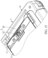
- FIG. 15 is a schematic view of the electronic device according to a fifth embodiment of the present invention
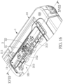
- FIG. 16 is a partial schematic enlarged view of the electronic device according to the present embodiment
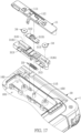
- FIG. 17 is a partial schematic exploded view of the electronic device according to the present embodiment
- FIG. 18 is a schematic cross-sectional view taken along line XVIII-XVIII of FIG. 16 according to the present embodiment
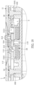
- FIG. 19 is a schematic cross-sectional view of the electronic device according to the present embodiment.
- the detachable electronic module 2 can include a battery arranged therein.
- the switch mechanism 3 of the present embodiment can include an elastic member 33, and two locking members 34.
- the pushing member 31 includes a first component 315 and a second component 316.
- the first component 315 is fixed to the second component 316.
- the second component 316 is movably disposed on the housing body 10.
- the second component 316 can include two sliding grooves 3161.
- the two locking members 34 are threaded with the two threaded holes 102 of the housing body 10 through the two sliding grooves 3161, so that the second component 316 is slidably disposed on the housing body 10.
- the first component 315 includes the manipulation portion 312.
- the elastic member 33 can be a spring. Two ends of the elastic member 33 are respectively fixed to the housing body 10 and the second component 316.
- the second component 316 includes two barrier structures 313. The cooperation between the barrier structures 313 and the engaging portions 211 of the detachable electronic modules 2 are described in the above description and will be omitted herein for the sake of brevity.
- the first component 315 has a through hole 3151
- the housing body 10 has a threaded hole 115.
- the through hole 3151 and the threaded hole 115 are in spatial communication with each other, the through hole 3151 and the threaded hole 115 are exposed from the opening 112 of the switch shell 11, and the limiting member 32 can be threaded with the threaded hole 115 by passing through the through hole 3151. Accordingly, the first component 315 and the second component 316 are fixed to the housing body 10 through the limiting member 32, and the pushing member 31 cannot be moved to the unlocked position.
- the pushing member 31 when the pushing member 31 is located at the unlocked position, the through hole 3151 of the first component 315 is arranged in the activity space S and is not exposed from the opening 112, and the elastic member 33 is in a stretched state.
- the pushing member 31 can be affected by the elastic restoring force of the elastic member 33 so as to be moved from the unlocked position to the locked position.
- the first component 315 and the second component 316 can be integrally formed as a single one-piece structure; and in another variation of the present embodiment, the electronic device 100 can be provided without the elastic member 33.
- the elastic member 33 of the present embodiment can be included according to practical requirements.
- the electromagnet 4 disclosed in the aforementioned embodiments can be combined with the pushing member 31 including the first component 315 and the second component 316 of the present embodiment so as to jointly form a new configuration.
- the arrangement of the pushing member and the limiting member provided in the switch mechanism prevents the detachable electronic module (the detachable modules) from being easily detached from the housing according to practical requirements, thereby effectively improving on the above issues that the conventional detachable electronic modules (e.g., batteries or solid-state drives) assembled in the rugged laptop computer can easily detach from the housing and/or be stolen.
- the conventional detachable electronic modules e.g., batteries or solid-state drives
Landscapes
- Engineering & Computer Science (AREA)
- Theoretical Computer Science (AREA)
- Computer Hardware Design (AREA)
- General Engineering & Computer Science (AREA)
- Human Computer Interaction (AREA)
- Physics & Mathematics (AREA)
- General Physics & Mathematics (AREA)
- Power Engineering (AREA)
- Signal Processing (AREA)
- Casings For Electric Apparatus (AREA)
Abstract
An electronic device (100) includes a housing (1), a detachable module (2), and a switch mechanism (3). The detachable module (2) is detachably disposed in an accommodating chamber (101) of the housing (1). The switch mechanism (3) includes a pushing member (31) and a limiting member (32). The pushing member (31) is movable relative to the housing (1) between a locked position and an unlocked position. When the detachable module (2) is disposed in the accommodating chamber (101) and the pushing member (31) is located at the unlocked position, the detachable module (2) is able to be disassembled from the accommodating chamber (101). When the detachable module (2) is disposed in the accommodating chamber (101), the pushing member (31) is located at the locked position, and the limiting member (32) is located at a limited position, the detachable module (2) is fixed to the housing (1), and the pushing member (31) is restricted by the limiting member (32) and is not movable to the unlocked position.
Description
- The present invention relates to an electronic device, and more particularly to an electronic device having detachable electronic modules.
- In use, detachable electronic modules (e.g., batteries and solid-state drives) on a conventional electronic device (e.g., a laptop computer) may be unintentionally detached from the conventional electronic device. For example, when the laptop computer falls to the ground, the detachable electronic modules (e.g., batteries and solid-state drives) may be easily detached from the laptop computer.
- On the other hand, the detachable electronic modules can also easily be intentionally detached from the conventional electronic device. Accordingly, any person with malicious intent can easily detach the detachable electronic modules from the conventional electronic device. In a real-world situation, when the detachable electronic modules are solid-state drives that have confidential information stored therein, the person with malicious intent can easily remove the detachable electronic modules from the conventional electronic device and cause trouble for users thereof.
- The present invention provides an electronic device for improving on the issues associated with conventional electronic devices having detachable electronic modules that easily detach therefrom or are easily stolen by people with malicious intent.
- One of the technical aspects adopted by the present invention is to provide an electronic device. The electronic device includes a housing, a detachable electronic module, and a switch mechanism. The housing includes an accommodating chamber, and the detachable electronic module is detachably assembled to the accommodating chamber of the housing. The switch mechanism is disposed on the housing, and the switch mechanism includes a pushing member and a limiting member. The pushing member is movable relative to the housing between a locked position and an unlocked position. When the detachable electronic module is assembled to the accommodating chamber and the pushing member is located at the unlocked position, the detachable electronic module is able to be disassembled from the accommodating chamber of the housing. When the detachable electronic module is assembled to the accommodating chamber, the pushing member is located at the locked position, and the limiting member is located at a limited position, such that the detachable electronic module is fixed to the housing, and the pushing member is limited by the limiting member and is not movable to the unlocked position.
- Therefore, in the electronic device provided by the present invention, through the arrangement of the pushing member and the limiting member provided in the switch mechanism, when the detachable electronic module is assembled in the accommodating chamber and the pushing member and the limiting member are respectively located at the locked position and the limited position, the detachable electronic module is not easily detached from the electronic device.
- These and other aspects of the present invention will become apparent from the following description of the embodiment taken in conjunction with the following drawings and their captions, although variations and modifications therein may be affected without departing from the scope of the novel concepts of the invention.
- The described embodiments may be better understood by reference to the following description and the accompanying drawings, in which:
-
FIG. 1 is a schematic perspective view showing a bottom side of an electronic device according to a first embodiment of the present invention; -
FIG. 2 is a schematic partial enlarged view of the electronic device according to the first embodiment of the present invention; -
FIG. 3 is a schematic partial exploded view of the electronic device according to the first embodiment of the present invention; -
FIG. 4 is a schematic exploded view of a housing and a detachable electronic module of the electronic device according to the first embodiment of the present invention; -
FIG. 5 is a schematic exploded view of the housing and a pushing member of the electronic device according to the first embodiment of the present invention; -
FIG. 6 is a schematic cross-sectional view taken along line VI-VI ofFIG. 2 according to the first embodiment of the present invention; -
FIG. 7 is a schematic cross-sectional view of the electronic device according to the first embodiment of the present invention; -
FIG. 8 is a schematic cross-sectional view taken along line VIII-VIII ofFIG. 4 according to the first embodiment of the present invention; -
FIG. 9 is a schematic cross-sectional view of the electronic device according to the first embodiment of the present invention; -
FIG. 10 is a schematic cross-sectional view of the electronic device according to a second embodiment of the present invention; -
FIG. 11 is a schematic cross-sectional view of the electronic device according to a third embodiment of the present invention; -
FIG. 12 andFIG. 13 are cross-sectional views showing the electronic device in different states according to a fourth embodiment of the present invention; -
FIG. 14 is a block diagram of the electronic device according to the fourth embodiment of the present invention; -
FIG. 15 is a schematic view of the electronic device according to a fifth embodiment of the present invention; -
FIG. 16 is a partial schematic enlarged view of the electronic device according to the fifth embodiment of the present invention; -
FIG. 17 is a partial schematic exploded view of the electronic device according to the fifth embodiment of the present invention; -
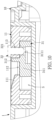
FIG. 18 is a schematic cross-sectional view taken along line XVIII-XVIII ofFIG. 16 according to the fifth embodiment of the present invention; and -
FIG. 19 is a schematic cross-sectional view of the electronic device according to the fifth embodiment of the present invention. - The present invention is more particularly described in the following examples that are intended as illustrative only since numerous modifications and variations therein will be apparent to those skilled in the art. Like numbers in the drawings indicate like components throughout the views. As used in the description herein and throughout the claims that follow, unless the context clearly dictates otherwise, the meaning of "a," "an" and "the" includes plural reference, and the meaning of "in" includes "in" and "on." Titles or subtitles can be used herein for the convenience of a reader, which shall have no influence on the scope of the present invention.
- The terms used herein generally have their ordinary meanings in the art. In the case of conflict, the present document, including any definitions given herein, will prevail. The same thing can be expressed in more than one way. Alternative language and synonyms can be used for any term(s) discussed herein, and no special significance is to be placed upon whether a term is elaborated or discussed herein. A recital of one or more synonyms does not exclude the use of other synonyms. The use of examples anywhere in this specification including examples of any terms is illustrative only, and in no way limits the scope and meaning of the present invention or of any exemplified term. Likewise, the present invention is not limited to various embodiments given herein. Numbering terms such as "first," "second" or "third" can be used to describe various components, signals or the like, which are for distinguishing one component/signal from another one only, and are not intended to, nor should be construed to impose any substantive limitations on the components, signals or the like.
- As shown in
FIG. 1 to FIG. 5 ,FIG. 1 is a schematic perspective view showing a bottom side of an electronic device according to a first embodiment of the present invention,FIG. 2 is a partial schematic enlarged view of the electronic device in the present embodiment,FIG. 3 is a partial schematic exploded view of the electronic device in the first embodiment,FIG. 4 is a schematic exploded view of a housing and a detachable electronic module of the electronic device in the present embodiment, andFIG. 5 is a schematic exploded view of the housing and a pushing member of the electronic device in the present embodiment. - The
electronic device 100 in the present invention includes ahousing 1, three detachable electronic modules 2 (e.g., detachable modules 2), and threeswitch mechanisms 3. Thedetachable modules 2 in this embodiment, for example, are detachable electronic modules, but the present invention is not limited thereto. Each of the detachableelectronic modules 2 is detachably assembled to thehousing 1, each of theswitch mechanisms 3 is disposed on thehousing 1, and each of theswitch mechanisms 3 is disposed on one of the detachableelectronic modules 2 adjacent thereto. Each of theswitch mechanisms 3 is configured to provide a manipulation of a user, such that the detachableelectronic modules 2 are fixed to thehousing 1. Moreover, a quantity of the detachableelectronic modules 2 and a quantity of theswitch mechanisms 3 provided in theelectronic device 100 can be changed according to practical requirements and are not limited by the present embodiment. - The
electronic device 100 can be applied as a laptop computer, a tablet computer, etc., and is particularly suitable for use as a rugged computer. The rugged computer is suitable for use by units that need to process sensitive data, such as military units, intelligence units, etc., but is not limited by the present embodiment. If theelectronic device 100 is used as the laptop computer, theelectronic device 100 includes a screen, a keyboard, a hard disk drive and other components provided in the laptop computer. In the following description, only the differences between theelectronic device 100 of the present invention and the conventional laptop computer will be described, and the parts that are not described in detail can be designed according to practical requirements with reference to the conventional laptop computer. - The
housing 1 includes ahousing body 10 and threeswitch shells 11. Thehousing body 10 includes threeaccommodating chambers 101, and each of theaccommodating chambers 101 is configured to accommodate one of the detachableelectronic modules 2. Thehousing body 10 is provided to be an outer housing and a main support structure of theelectronic device 100, the threeswitch shells 11 are fixed to thehousing body 10, and each of theswitch shells 11 is used to shield and limit a movable range of a pushingmember 31 of one of theswitch mechanisms 3. - Each of the detachable
electronic modules 2 is detachably assembled to one of theaccommodating chambers 101 of thehousing 1. Theswitch mechanism 3 includes the pushingmember 31 and a limitingmember 32. The pushingmember 31 is movable relative to thehousing 1 between a locked position and an unlocked position. In practice, thehousing 1 can have guide structures 104 (e.g., various sliding grooves and/or various slide rails), a part of the pushingmember 31 is slidably connected to theguide structures 104, and the pushingmember 31 is slidable relative thehousing 1 through theguide structures 104. The limitingmember 32 can be a screw, but the present invention is not limited thereto. In the embodiment in which the limitingmember 32 is the screw, a manipulation hole of the limitingmember 32 is not crossed or slotted, and is a specially shaped hole. In other words, the limitingmember 32 cannot be removed directly by using common tools (e.g., a screwdriver-crossed or a screwdriver-slotted). - As shown in
FIG. 2 , when the pushingmember 31 is located at the locked position, the pushingmember 31 is provided to limit and fix the detachableelectronic module 2 to thehousing 1, such that the user is basically unable to directly pull the detachableelectronic module 2 and disassemble the detachableelectronic module 2 from the accommodating chamber 101 (as shown inFIG. 4 ). In the situation shown inFIG. 2 , the limitingmember 32 is located at a limited position, and the pushingmember 31 is limited by the limitingmember 32, such that the pushingmember 31 cannot be manipulated to be moved from the locked position shown inFIG. 2 to the unlocked position shown inFIG. 4 . In other words, in the situation ofFIG. 2 , the user cannot disassemble the detachableelectronic module 2 from theaccommodating chamber 101 with bare hands when the user does not use any tool (e.g., a screwdriver). - As shown in
FIG. 3 to FIG. 5 , when the user uses a tool (e.g., a screwdriver) to disassemble the limitingmember 32 from thehousing 1, the pushingmember 31 is no longer limited by the limitingmember 32, and the pushingmember 31 can be pushed to the unlocked position shown inFIG. 3 , such that the user can pull the detachableelectronic module 2 with their bare hands to disassemble the detachableelectronic module 2 from theaccommodating chamber 101. - In summary, in the
electronic device 100 of the present invention, thehousing 1, theswitch mechanisms 3, and the detachableelectronic modules 2 are provided to be in cooperation with each other, such that the user can fix the detachableelectronic modules 2 to thehousing 1 according to practical requirements, thereby preventing the detachableelectronic modules 2 from being easily disassembled from thehousing 1 by people with malicious intent and preventing the detachableelectronic modules 2 from being easily detached from thehousing 1. - Specifically, in a conventional rugged laptop computer provided for military or intelligence units that require processing of confidential information, in order to prevent the confidential information from being leaked, the confidential information is stored in a solid-state drive (SSD) that can be quickly and detachably assembled to the rugged laptop computer. When the relevant personnel get off work, the solid-state drive can be disassembled and placed in a specific place for safekeeping. During work hours, the relevant personnel can reassemble the solid-state drive to the rugged laptop computer. However, in this application scenario, when the solid-state drive is assembled to the rugged laptop computer, the solid-state drive can easily be unexpectedly detached from the rugged laptop computer by an external force, causing trouble to the user. In addition, when the solid-state drive is assembled on the rugged laptop computer, the solid-state drive can easily be deliberately disassembled from the rugged laptop computer by people with malicious intent.
- The
electronic device 100 of the present invention is provided with theswitch mechanisms 3, such that the relevant personnel can manipulate the limitingmember 32 to be located at the limited position for preventing the pushingmember 31 from being manipulated, thereby fixing the detachableelectronic modules 2 to thehousing 1. Accordingly, the detachableelectronic modules 2 can be prevented from being detached from thehousing 1, thereby effectively solving the above issues of the conventional rugged laptop computer. Furthermore, in the embodiment in which the limitingmember 32 is the screw, the size of the threaded hole and the shape of the operating hole of the limitingmember 32 can have a special design, so that if theelectronic device 100 is stolen by someone other than the user, the detachableelectronic modules 2 still cannot be quickly disassembled from thehousing 1 with an appropriate tool. - As shown in
FIG. 5 to FIG. 9 ,FIG. 6 is a schematic cross-sectional view taken along line VI-VI ofFIG. 2 according to the first embodiment of the present invention,FIG. 7 is a schematic cross-sectional view of the present embodiment,FIG. 8 is a schematic cross-sectional view taken along line VIII-VIII ofFIG. 4 of the present embodiment, andFIG. 9 is a schematic cross-sectional view of the present embodiment. - The
switch shell 11 of thehousing 1 is fixed to thehousing body 10 of thehousing 1 through a threaded manner or an engaging manner. Theswitch shell 11 includes aninclined sidewall 111 and anopening 112, theinclined sidewall 111 surrounds theopening 112, and theopening 112 is a hole that penetrates theswitch shell 11. When theswitch shell 11 is fixed to thehousing body 10, theswitch shell 11 and thehousing body 10 jointly define an activity space S. The activity space S is arranged in thehousing 1, and the activity space S is in spatial communication with an external environment through theopening 112. - The pushing
member 31 includes amain body 311 and amanipulation portion 312. Themain body 311 is arranged in the activity space S, and themanipulation portion 312 protrudes from theopening 112. Themanipulation portion 312 is configured to provide a manipulation of the user, such that the pushingmember 31 can be moved between the locked position and the unlocked position. Themain body 311 can include a threadedhole 3111, the limitingmember 32 can be the screw, and the limitingmember 32 can be threaded with the threadedhole 3111. - As shown in
FIG. 2 ,FIG. 3 ,FIG. 6 , andFIG. 7 , when the pushingmember 31 is located at the locked position as shown inFIG. 3 , the threadedhole 3111 of themain body 311 is exposed from theopening 112, the threadedhole 3111 of themain body 311 and theopening 112 of theswitch shell 11 are in spatial communication with each other, and the limitingmember 32 can be threaded with the threadedhole 3111 through theopening 112. When the limitingmember 32 and the threadedhole 3111 are threaded with each other, the limitingmember 32 is located at the limited position, atop portion 321 of the limitingmember 32 is located in theopening 112, and thetop portion 321 is located between themanipulation portion 312 and theinclined sidewall 111. Accordingly, themanipulation portion 312 can be blocked by thetop portion 321 and cannot be moved to the unlocked position as shown inFIG. 4 . - As shown in
FIG. 3 ,FIG. 4 ,FIG. 8 , andFIG. 9 , when the limitingmember 32 is detached from the threadedhole 3111 and is not located at the limited position, the pushingmember 31 located at the locked position as shown inFIG. 3 can be moved to the locked position as shown inFIG. 4 by being pushed. When the pushingmember 31 is located at the unlocked position, the threadedhole 3111 is not exposed from theopening 112, and the threadedhole 3111 is arranged in theswitch shells 11. - As shown in
FIG. 4 , in practice, the detachableelectronic module 2 can include acasing 21, a plurality ofelectronic modules 22, and aconnector 23, and theelectronic modules 22 are disposed in thecasing 21. Theelectronic modules 22 can include a circuit board and a plurality of random access memory, and theelectronic modules 22 can be a solid-state drive (SSD). A part of theconnector 23 is exposed from thecasing 21, and theconnector 23 is used for being connected to a connector arranged in thehousing 1. Thecasing 21 includes twoengaging portions 211 that are spaced apart from each other. When the detachableelectronic module 2 is assembled into theaccommodating chamber 101, the twoengaging portions 211 are disposed adjacent to theswitch mechanism 3. As shown inFIG. 4 andFIG. 5 , themain body 311 of the pushingmember 31 can include twobarrier structures 313 that are spaced apart from each other. In another embodiment, thedetachable module 2 includes acasing 21 with twoengaging portions 211. Thecasing 21 can cover theaccommodating chamber 101 of thehousing 1. - As shown in
FIG. 6 andFIG. 7 , when the pushingmember 31 is located at the locked position, thebarrier structures 313 of the pushingmember 31 are correspondingly located above the engagingportions 211 of the detachableelectronic module 2. Accordingly, even if the limitingmember 32 is not threaded with the threadedhole 3111, the detachableelectronic module 2 is still blocked by thebarrier structures 313 through the engagingportions 211, such that the detachableelectronic module 2 cannot be detached from theaccommodating chamber 101. - As shown in
FIG. 8 andFIG. 9 , when the pushingmember 31 is located at the unlocked position, the threadedhole 3111 is not exposed from theopening 112, and thebarrier structures 313 of the pushingmember 31 are not located above the engagingportions 211 of the detachableelectronic module 2, so that the relevant personnel can pull the detachableelectronic module 2 to disassemble the detachableelectronic module 2 from theaccommodating chamber 101. - In conclusion, in one of the specific embodiments, the connection and position relationship among the
housing 1, the limitingmember 32, the pushingmember 31, and the detachable electronic modules 2 (e.g., the detachable modules 2) can be implemented or provided according to the above description, but the present invention is not limited thereto. - As shown in
FIG. 10, FIG. 10 is a schematic cross-sectional view of the electronic device according to a second embodiment of the present invention. The main difference between the present embodiment and the first embodiment as shown inFIG. 6 is described as follows: the position of the threadedhole 3111 included by themain body 311 of the pushingmember 31 in the present embodiment is different from the position of the threadedhole 3111 shown inFIG. 6 , and theswitch shell 11 of thehousing 1 includes a throughhole 113. In the present embodiment, when the pushingmember 31 is located at the locked position, the threadedhole 3111 of the pushingmember 31 and the throughhole 113 of theswitch shell 11 are in spatial communication with each other, and the limitingmember 32 is capable of passing through the throughhole 113 to be threaded with the threadedhole 3111. Accordingly, the pushingmember 31 can be limited by the limitingmember 32, such that the pushingmember 31 cannot be moved to the unlocked position. - As shown in
FIG. 11, FIG. 11 is a schematic cross-sectional view of the electronic device according to a third embodiment of the present invention. The main difference between the present embodiment and the first embodiment as shown inFIG. 6 is described as follows: the pushingmember 31 in the present embodiment does not have the threaded hole, and theswitch shell 11 has a threadedhole 114. In the present embodiment, when the pushingmember 31 is located at the locked position and is threaded with the threadedhole 114 of theswitch shell 11, a part of the limitingmember 32 is arranged in the activity space S, so that the pushingmember 31 is blocked by the part of the limitingmember 32 arranged in the activity space S, and the pushingmember 31 cannot be moved to the unlocked position. It should be noted that, the limitingmember 32 threaded with the threadedhole 114 is mainly configured to prevent the pushingmember 31 from being moved to the unlocked position, such that when the limitingmember 32 is threaded with the threadedhole 114, the part of the limitingmember 32 arranged in the activity space S is located on a path of the pushingmember 31 from the locked position to the unlocked position. - As shown in
FIG. 12 to FIG. 14 ,FIG. 12 andFIG. 13 are cross-sectional views showing the electronic device in different states according to a fourth embodiment of the present invention, andFIG. 14 is a block diagram of the electronic device according to the present embodiment. Theelectronic device 100 can include anelectromagnet 4 and acontrol module 5. Theelectromagnet 4 is electrically connected to thecontrol module 5, and thecontrol module 5 can be a microprocessor that is independent from acentral processing unit 6 of the laptop computer. It should be noted that, in particular implementations, thecontrol module 5 and thecentral processing unit 6 can also be integrated into a same module. Thecontrol module 5 is configured to control theelectromagnet 4 to change a magnetism of theelectromagnet 4. Theelectromagnet 4 is disposed in thehousing 1, and theelectromagnet 4 is disposed adjacent to the pushingmember 31. The limitingmember 32 is disposed in thehousing 1, and at least part of the limitingmember 32 has the magnetism. In practice, the limitingmember 32 can include apermanent magnet 322 arranged therein. The limitingmember 32 can be moved along anactive channel 12 in thehousing 1. In practice, theactive channel 12 can be formed in a relevant support structure arranged in thehousing 1, or theactive channel 12 can be formed in a circuit board that is disposed in thehousing 1. - As shown in
FIG. 12 , when the pushingmember 31 is located at the locked position and thecontrol module 5 controls the magnetism of theelectromagnet 4 to be identical to the magnetism of the limitingmember 32, thepermanent magnet 322 in the limitingmember 32 is moved to the limited position as shown inFIG. 12 along theactive channel 12 because like poles repel one another. When the limitingmember 32 is moved to the limited position, a part of the limitingmember 32 is located in a throughhole 314 of the pushingmember 31, so that the pushingmember 31 is limited by the limitingmember 32 and cannot be moved to the unlocked position. - As shown in
FIG. 13 , when thecontrol module 5 controls the magnetism of theelectromagnet 4 to be opposite to the magnetism of the limitingmember 32, thepermanent magnet 322 of the limitingmember 32 is moved from the limited position as shown inFIG. 12 to a non-limited position as shown in FIG. - 13 because opposite poles attract each other, such that a part of the limiting
member 32 is no longer located in the throughhole 314 of the pushingmember 31. When the limitingmember 32 is not located in the throughhole 314 of the pushingmember 31, the pushingmember 31 can be moved from the locked position to the unlocked position. - In summary, the
central processing unit 6 of theelectronic device 100 can be used to run anunlock application 7 in practical implementation. Theunlock application 7 can be installed and executed in an operating system, but the present invention is not limited thereto. In a different embodiment, theunlock application 7 can be installed and executed in a basic input/output system (BIOS). - When the
central processing unit 6 runs theunlock application 7, the user can see an application interface on a display of theelectronic device 100, and the application interface can show fields that require the user to enter an account number and a password. When the user enters the correct account number and the correct password in the application interface, thecentral processing unit 6 can control the magnetism of theelectromagnet 4 through thecontrol module 5, so as to enable the limitingmember 32 to be moved to the non-limited position. Accordingly, the pushingmember 31 can be moved from the locked position to the unlocked position. Conversely, if the incorrect account number and the incorrect password are entered, thecentral processing unit 6 cannot control the magnetism of theelectromagnet 4 through thecontrol module 5, so that the limitingmember 32 is maintained at the limited position, and the pushingmember 31 cannot be moved to the unlocked position. - It should be noted that the positions of the limiting
member 32 and theelectromagnet 4 of present embodiment are just one of possible arrangements. In different embodiments, the positions of the limitingmember 32 and theelectromagnet 4 can be adjusted or changed according toFIG. 10 andFIG. 11 . In different embodiments, as long as the limitingmember 32 is located at the limited position by being driven from theelectromagnet 4, and at least part of the limitingmember 32 is located on a path of the pushingmember 31 from locked position to unlocked position, the positions of theelectromagnet 4 and the limitingmember 32 can be changed according to practical requirements. - As shown in
FIG. 15 to FIG. 19 ,FIG. 15 is a schematic view of the electronic device according to a fifth embodiment of the present invention,FIG. 16 is a partial schematic enlarged view of the electronic device according to the present embodiment,FIG. 17 is a partial schematic exploded view of the electronic device according to the present embodiment,FIG. 18 is a schematic cross-sectional view taken along line XVIII-XVIII ofFIG. 16 according to the present embodiment, andFIG. 19 is a schematic cross-sectional view of the electronic device according to the present embodiment. - In the present embodiment, the detachable
electronic module 2 can include a battery arranged therein. As shown inFIG. 15 to FIG. 17 , the main difference between the present embodiment and the aforementioned embodiments is described as follows: theswitch mechanism 3 of the present embodiment can include anelastic member 33, and two lockingmembers 34. The pushingmember 31 includes afirst component 315 and asecond component 316. Thefirst component 315 is fixed to thesecond component 316. Thesecond component 316 is movably disposed on thehousing body 10. - In practice, the
second component 316 can include two slidinggrooves 3161. The twolocking members 34 are threaded with the two threadedholes 102 of thehousing body 10 through the two slidinggrooves 3161, so that thesecond component 316 is slidably disposed on thehousing body 10. Thefirst component 315 includes themanipulation portion 312. Theelastic member 33 can be a spring. Two ends of theelastic member 33 are respectively fixed to thehousing body 10 and thesecond component 316. Thesecond component 316 includes twobarrier structures 313. The cooperation between thebarrier structures 313 and the engagingportions 211 of the detachableelectronic modules 2 are described in the above description and will be omitted herein for the sake of brevity. - As shown in
FIG. 17 to FIG. 18 , thefirst component 315 has a throughhole 3151, and thehousing body 10 has a threadedhole 115. When the pushingmember 31 is located at the locked position, the throughhole 3151 and the threadedhole 115 are in spatial communication with each other, the throughhole 3151 and the threadedhole 115 are exposed from theopening 112 of theswitch shell 11, and the limitingmember 32 can be threaded with the threadedhole 115 by passing through the throughhole 3151. Accordingly, thefirst component 315 and thesecond component 316 are fixed to thehousing body 10 through the limitingmember 32, and the pushingmember 31 cannot be moved to the unlocked position. - As shown in
FIG. 19 , when the pushingmember 31 is located at the unlocked position, the throughhole 3151 of thefirst component 315 is arranged in the activity space S and is not exposed from theopening 112, and theelastic member 33 is in a stretched state. When theelastic member 33 is in the stretched state and the user does not manipulate the pushingmember 31, the pushingmember 31 can be affected by the elastic restoring force of theelastic member 33 so as to be moved from the unlocked position to the locked position. - It should be noted that, in one variation of the present embodiment, the
first component 315 and thesecond component 316 can be integrally formed as a single one-piece structure; and in another variation of the present embodiment, theelectronic device 100 can be provided without theelastic member 33. In any one of the above embodiments, theelastic member 33 of the present embodiment can be included according to practical requirements. Theelectromagnet 4 disclosed in the aforementioned embodiments can be combined with the pushingmember 31 including thefirst component 315 and thesecond component 316 of the present embodiment so as to jointly form a new configuration. - In conclusion, in the electronic device provided by the present invention, the arrangement of the pushing member and the limiting member provided in the switch mechanism prevents the detachable electronic module (the detachable modules) from being easily detached from the housing according to practical requirements, thereby effectively improving on the above issues that the conventional detachable electronic modules (e.g., batteries or solid-state drives) assembled in the rugged laptop computer can easily detach from the housing and/or be stolen.
- The foregoing description of the exemplary embodiments of the invention has been presented only for the purposes of illustration and description and is not intended to be exhaustive or to limit the invention to the precise forms disclosed. Many modifications and variations are possible in light of the above teaching.
- The embodiments were chosen and described in order to explain the principles of the invention and their practical application so as to enable others skilled in the art to utilize the invention and various embodiments and with various modifications as are suited to the particular use contemplated. Alternative embodiments will become apparent to those skilled in the art to which the present invention pertains without departing from its scope.
Claims (15)
- An electronic device (100), characterized by comprising:a housing (1) comprising an accommodating chamber (101);a detachable module (2) detachably assembled to the accommodating chamber (101) of the housing (1); anda switch mechanism (3) disposed on the housing (1), and the switch mechanism (3) comprising a pushing member (31) and a limiting member (32), wherein the pushing member (31) is movable relative to the housing (1) between a locked position and an unlocked position;wherein, when the detachable module (2) is assembled to the accommodating chamber (101) and the pushing member (31) is located at the unlocked position, the detachable module (2) is able to be disassembled from the accommodating chamber (101) of the housing (1);wherein, when the detachable module (2) is assembled to the accommodating chamber (101), the pushing member (31) is located at the locked position and the limiting member (32) is located at a limited position, such that the detachable module (2) is fixed to the housing (1), and the pushing member (31) is limited by the limiting member (32) to not be movable to the unlocked position.
- The electronic device (100) according to claim 1, wherein the housing (1) comprises an inclined sidewall (111), an opening (112), and an activity space (S); wherein the inclined sidewall (111) surrounds the opening (112), the activity space (S) is arranged in the housing (1), and the activity space (S) is in spatial communication with an external environment through the opening (112); wherein the pushing member (31) comprises a main body (311) and a manipulation portion (312), the main body (311) is arranged in the activity space (S), and the manipulation portion (312) protrudes from the opening (112).
- The electronic device (100) according to claim 2, wherein the housing (1) comprises a housing body (10) and a switch shell (11), the housing body (10) comprises the accommodating chamber (101), the switch shell (11) is fixed to the housing body (10), the switch shell (11) comprises the inclined sidewall (111) and the opening (112), and the switch shell (11) and the housing body (10) jointly define the activity space (S).
- The electronic device according to claim 2, wherein the main body (311) comprises a threaded hole (3111), when the limiting member (32) is threaded with the threaded hole (3111), the limiting member (32) is located at the limited position; wherein, when the limiting member (32) is located at the limited position, a top portion (321) of the limiting member (32) is located in the opening (112), and the top portion (321) cooperates with the inclined sidewall (111), such that the pushing member (31) is not movable to the unlocked position; wherein, when the pushing member (31) is located at the locked position, the threaded hole (3111) is exposed from the opening (112), and wherein, when the pushing member (31) is located at the unlocked position, the threaded hole (3111) is not exposed from the opening (112).
- The electronic device (100) according to claim 1, wherein the housing (1) comprises a through hole (113), and the pushing member (31) comprises a threaded hole (3111); wherein, when the pushing member (31) is located at the locked position, the through hole (113) and the threaded hole (3111) are in spatial communication with each other, and the limiting member (32) is threaded with the threaded hole (3111) by passing through the through hole (113); and wherein, when the limiting member (32) is threaded with the threaded hole (3111), the limiting member (32) is located at the limited position.
- The electronic device (100) according to claim 1, wherein the housing (1) comprises a threaded hole (114), and wherein, when the limiting member (32) is threaded with the threaded hole (114) of the housing (1), a part of the limiting member (32) is arranged in the housing (1), the limiting member (32) is located at the limited position, and the pushing member (31) is blocked by the limiting member (32) arranged in the housing (1), such that the pushing member (31) is not movable from the locked position to the unlocked position.
- The electronic device (100) according to any of claim 1 to 6, wherein the limiting member (32) comprises a manipulation hole, and the manipulation hole is configured to cooperate with a tool, such that the limiting member (32) is located at the limited position or away from the limited position.
- The electronic device (100) according to claim 1, wherein the detachable module (2) comprises an engaging portion (211); wherein, when the pushing member (31) is located at the locked position, the engaging portion (211) is blocked by a barrier structure (313) of the pushing member (31), such that the detachable module (2) is not able to be disassembled from the accommodating chamber (101) of the housing (1); and wherein, when the pushing member (31) is located at the unlocked position, the engaging portion (211) is not blocked by the barrier structure (313), such that the detachable module (2) is able to be disassembled from the accommodating chamber (101) of the housing (1).
- The electronic device (100) according to claim 1, wherein the electronic device (100) comprises an elastic member (33) disposed in the housing (1), an end of the elastic member (33) is fixed to the housing (1), and a second end of the elastic member (33) is fixed to the pushing member (31); and wherein, when the pushing member (31) is located at the locked position or the unlocked position, the elastic member (33) is stretched and elastically deformed.
- The electronic device (100) according to any of claim 1 to 3, wherein the electronic device (100) further comprises an electromagnet (4) and a control module (5), the electromagnet (4) and the control module (5) are disposed in the housing (1), at least part of the limiting member (32) has a magnetism, the control module (5) is configured to control a magnetism of the electromagnet (4), such that the magnetism of the electromagnet (4) and the magnetism of the part of the limiting member (32) are same as or different from each other to enable the limiting member (32) to be movable between the limited position and a non-limited position; wherein, when the detachable module (2) is assembled to the accommodating chamber (101), the pushing member (31) is located at the locked position, the limiting member (32) is located at the non-limited position, and the pushing member (31) is movable to the unlocked position.
- The electronic device (100) according to claim 10, wherein the main body (311) comprises a through hole (314); wherein, when the limiting member (32) is located at the limited position, a second part of the limiting member (32) is disposed in the through hole (314); and wherein, when the limiting member (32) is located at the non-limited position, the limiting member (32) is not disposed in the through hole (314), and the pushing member (31) is movable between the unlocked position and the locked position.
- The electronic device (100) according to claim 10, wherein the electronic device (100) further comprises a central processing unit (6), the central processing unit (6) is electrically connected to the control module (5), the central processing unit (6) is configured to run an unlock application (7), and the unlock application (7) comprises an application interface; and wherein, when a correct password is entered into the application interface, the unlock application is configured to control the control module (5) through the central processing unit (6) to change the magnetism of the electromagnet (4) to enable the limiting member (32) to move to the non-limited position or the limited position.
- The electronic device (100) according to claim 1, wherein the housing (1) comprises at least one guide structure (104), a part of the pushing member (31) is slidably connected to the at least one guide structure (104), and the pushing member (31) is slidable relative the housing (1) through the at least one guide structure (104).
- The electronic device (100) according to claim 13, wherein the detachable module (2) comprises a casing (21) with an engaging portion (211); wherein, when the pushing member (31) is located at the locked position, the engaging portion (211) is blocked by a barrier structure (313) of the pushing member (31), such that the detachable module (2) is not able to be disassembled from the accommodating chamber (101) of the housing (1); and wherein, when the pushing member (31) is located at the unlocked position, the engaging portion (211) is not blocked by the barrier structure (313), such that the detachable module (2) is able to be disassembled from the accommodating chamber (101) of the housing (1).
- The electronic device (100) according to any of the preceding claims, wherein the detachable module (2) is a detachable electronic module (2), and wherein the detachable electronic module (2) comprises a casing (21) and an electronic module (22), the electronic module (22) is disposed in the casing (21), and the electronic module (22) is a solid-state drive or a battery.
Applications Claiming Priority (1)
| Application Number | Priority Date | Filing Date | Title |
|---|---|---|---|
| CN202311482363.9A CN119960556A (en) | 2023-11-08 | 2023-11-08 | Electronic Devices |
Publications (1)
| Publication Number | Publication Date |
|---|---|
| EP4553611A1 true EP4553611A1 (en) | 2025-05-14 |
Family
ID=92212661
Family Applications (1)
| Application Number | Title | Priority Date | Filing Date |
|---|---|---|---|
| EP24192609.6A Pending EP4553611A1 (en) | 2023-11-08 | 2024-08-02 | Electronic device |
Country Status (3)
| Country | Link |
|---|---|
| US (1) | US20250147556A1 (en) |
| EP (1) | EP4553611A1 (en) |
| CN (1) | CN119960556A (en) |
Citations (3)
| Publication number | Priority date | Publication date | Assignee | Title |
|---|---|---|---|---|
| US20120300427A1 (en) * | 2011-05-24 | 2012-11-29 | Hon Hai Precision Industry Co., Ltd. | Electronic device with detachable power module |
| US20170179448A1 (en) * | 2015-12-22 | 2017-06-22 | Getac Technology Corporation | Structure with detachable battery for electronic device |
| US20230097723A1 (en) * | 2021-09-24 | 2023-03-30 | Acer Incorporated | Pick-and-place mechanism for stylus |
-
2023
- 2023-11-08 CN CN202311482363.9A patent/CN119960556A/en active Pending
-
2024
- 2024-06-13 US US18/742,745 patent/US20250147556A1/en active Pending
- 2024-08-02 EP EP24192609.6A patent/EP4553611A1/en active Pending
Patent Citations (3)
| Publication number | Priority date | Publication date | Assignee | Title |
|---|---|---|---|---|
| US20120300427A1 (en) * | 2011-05-24 | 2012-11-29 | Hon Hai Precision Industry Co., Ltd. | Electronic device with detachable power module |
| US20170179448A1 (en) * | 2015-12-22 | 2017-06-22 | Getac Technology Corporation | Structure with detachable battery for electronic device |
| US20230097723A1 (en) * | 2021-09-24 | 2023-03-30 | Acer Incorporated | Pick-and-place mechanism for stylus |
Also Published As
| Publication number | Publication date |
|---|---|
| US20250147556A1 (en) | 2025-05-08 |
| CN119960556A (en) | 2025-05-09 |
Similar Documents
| Publication | Publication Date | Title |
|---|---|---|
| US6811415B2 (en) | Connector protecting device | |
| US11566448B2 (en) | Lock for faceplane infrastructure | |
| CN107368149B (en) | Connector assembly for electronic device | |
| US9146586B2 (en) | Electronic device | |
| US7835148B2 (en) | Portable storage device capable of being disassembled easily | |
| US10064307B2 (en) | Server and case thereof | |
| US20070109755A1 (en) | Modules for a measuring device and measuring device | |
| GB2369600A (en) | A system configuration or smart card with a notch for security | |
| US6634898B2 (en) | Switch mechanism for online replacement of PCI cards | |
| WO2008118266A1 (en) | Cable management system | |
| EP3136900A2 (en) | Protective case for a device | |
| EP3073411A1 (en) | Lan port lock device | |
| US20140160652A1 (en) | Power supply module and server having the same | |
| EP4145425A1 (en) | Impact resistant modular braille display device | |
| US20120113581A1 (en) | Implementing enhanced cover-mounted, auto-docking for multiple dasd configurations | |
| US7271337B2 (en) | Security block for a communications connector | |
| US8939523B2 (en) | Computer case protecting apparatus | |
| KR20050012927A (en) | Portable computer | |
| US20250147556A1 (en) | Electronic device | |
| US11977318B2 (en) | Portable electronic device and movable lens shutting module thereof | |
| US6837439B2 (en) | System configuration device security | |
| US7190575B1 (en) | Hard disk drive system and keying method | |
| US12235676B2 (en) | Support device and electronic system | |
| CN100409731C (en) | Measuring device and assembly for a measuring device | |
| US7542278B2 (en) | Electronic apparatus incorporating fixing mechanism |
Legal Events
| Date | Code | Title | Description |
|---|---|---|---|
| PUAI | Public reference made under article 153(3) epc to a published international application that has entered the european phase |
Free format text: ORIGINAL CODE: 0009012 |
|
| STAA | Information on the status of an ep patent application or granted ep patent |
Free format text: STATUS: THE APPLICATION HAS BEEN PUBLISHED |
|
| AK | Designated contracting states |
Kind code of ref document: A1 Designated state(s): AL AT BE BG CH CY CZ DE DK EE ES FI FR GB GR HR HU IE IS IT LI LT LU LV MC ME MK MT NL NO PL PT RO RS SE SI SK SM TR |
|
| STAA | Information on the status of an ep patent application or granted ep patent |
Free format text: STATUS: REQUEST FOR EXAMINATION WAS MADE |
|
| 17P | Request for examination filed |
Effective date: 20251007 |