EP4553551A2 - Optical engine lid with optical feedthrough - Google Patents
Optical engine lid with optical feedthrough Download PDFInfo
- Publication number
- EP4553551A2 EP4553551A2 EP24206804.7A EP24206804A EP4553551A2 EP 4553551 A2 EP4553551 A2 EP 4553551A2 EP 24206804 A EP24206804 A EP 24206804A EP 4553551 A2 EP4553551 A2 EP 4553551A2
- Authority
- EP
- European Patent Office
- Prior art keywords
- optical
- lid
- feedthrough
- engine
- substrate
- Prior art date
- Legal status (The legal status is an assumption and is not a legal conclusion. Google has not performed a legal analysis and makes no representation as to the accuracy of the status listed.)
- Pending
Links
Images





Classifications
-
- G—PHYSICS
- G02—OPTICS
- G02B—OPTICAL ELEMENTS, SYSTEMS OR APPARATUS
- G02B6/00—Light guides; Structural details of arrangements comprising light guides and other optical elements, e.g. couplings
- G02B6/24—Coupling light guides
- G02B6/42—Coupling light guides with opto-electronic elements
- G02B6/4292—Coupling light guides with opto-electronic elements the light guide being disconnectable from the opto-electronic element, e.g. mutually self aligning arrangements
-
- G—PHYSICS
- G02—OPTICS
- G02B—OPTICAL ELEMENTS, SYSTEMS OR APPARATUS
- G02B6/00—Light guides; Structural details of arrangements comprising light guides and other optical elements, e.g. couplings
- G02B6/24—Coupling light guides
- G02B6/42—Coupling light guides with opto-electronic elements
- G02B6/4201—Packages, e.g. shape, construction, internal or external details
- G02B6/4204—Packages, e.g. shape, construction, internal or external details the coupling comprising intermediate optical elements, e.g. lenses, holograms
- G02B6/421—Packages, e.g. shape, construction, internal or external details the coupling comprising intermediate optical elements, e.g. lenses, holograms the intermediate optical component consisting of a short length of fibre, e.g. fibre stub
-
- G—PHYSICS
- G02—OPTICS
- G02B—OPTICAL ELEMENTS, SYSTEMS OR APPARATUS
- G02B6/00—Light guides; Structural details of arrangements comprising light guides and other optical elements, e.g. couplings
- G02B6/24—Coupling light guides
- G02B6/42—Coupling light guides with opto-electronic elements
- G02B6/4201—Packages, e.g. shape, construction, internal or external details
- G02B6/4219—Mechanical fixtures for holding or positioning the elements relative to each other in the couplings; Alignment methods for the elements, e.g. measuring or observing methods especially used therefor
- G02B6/4228—Passive alignment, i.e. without a detection of the degree of coupling or the position of the elements
- G02B6/423—Passive alignment, i.e. without a detection of the degree of coupling or the position of the elements using guiding surfaces for the alignment
- G02B6/4231—Passive alignment, i.e. without a detection of the degree of coupling or the position of the elements using guiding surfaces for the alignment with intermediate elements, e.g. rods and balls, between the elements
-
- G—PHYSICS
- G02—OPTICS
- G02B—OPTICAL ELEMENTS, SYSTEMS OR APPARATUS
- G02B6/00—Light guides; Structural details of arrangements comprising light guides and other optical elements, e.g. couplings
- G02B6/24—Coupling light guides
- G02B6/42—Coupling light guides with opto-electronic elements
- G02B6/4201—Packages, e.g. shape, construction, internal or external details
- G02B6/4248—Feed-through connections for the hermetical passage of fibres through a package wall
-
- G—PHYSICS
- G02—OPTICS
- G02B—OPTICAL ELEMENTS, SYSTEMS OR APPARATUS
- G02B6/00—Light guides; Structural details of arrangements comprising light guides and other optical elements, e.g. couplings
- G02B6/24—Coupling light guides
- G02B6/42—Coupling light guides with opto-electronic elements
- G02B6/4201—Packages, e.g. shape, construction, internal or external details
- G02B6/4256—Details of housings
-
- G—PHYSICS
- G02—OPTICS
- G02B—OPTICAL ELEMENTS, SYSTEMS OR APPARATUS
- G02B6/00—Light guides; Structural details of arrangements comprising light guides and other optical elements, e.g. couplings
- G02B6/24—Coupling light guides
- G02B6/42—Coupling light guides with opto-electronic elements
- G02B6/4201—Packages, e.g. shape, construction, internal or external details
- G02B6/4256—Details of housings
- G02B6/4257—Details of housings having a supporting carrier or a mounting substrate or a mounting plate
-
- G—PHYSICS
- G02—OPTICS
- G02B—OPTICAL ELEMENTS, SYSTEMS OR APPARATUS
- G02B6/00—Light guides; Structural details of arrangements comprising light guides and other optical elements, e.g. couplings
- G02B6/24—Coupling light guides
- G02B6/42—Coupling light guides with opto-electronic elements
- G02B6/4201—Packages, e.g. shape, construction, internal or external details
- G02B6/4266—Thermal aspects, temperature control or temperature monitoring
- G02B6/4267—Reduction of thermal stress, e.g. by selecting thermal coefficient of materials
-
- G—PHYSICS
- G02—OPTICS
- G02B—OPTICAL ELEMENTS, SYSTEMS OR APPARATUS
- G02B6/00—Light guides; Structural details of arrangements comprising light guides and other optical elements, e.g. couplings
- G02B6/24—Coupling light guides
- G02B6/36—Mechanical coupling means
- G02B6/38—Mechanical coupling means having fibre to fibre mating means
- G02B6/3807—Dismountable connectors, i.e. comprising plugs
- G02B6/381—Dismountable connectors, i.e. comprising plugs of the ferrule type, e.g. fibre ends embedded in ferrules, connecting a pair of fibres
- G02B6/3818—Dismountable connectors, i.e. comprising plugs of the ferrule type, e.g. fibre ends embedded in ferrules, connecting a pair of fibres of a low-reflection-loss type
- G02B6/3821—Dismountable connectors, i.e. comprising plugs of the ferrule type, e.g. fibre ends embedded in ferrules, connecting a pair of fibres of a low-reflection-loss type with axial spring biasing or loading means
-
- G—PHYSICS
- G02—OPTICS
- G02B—OPTICAL ELEMENTS, SYSTEMS OR APPARATUS
- G02B6/00—Light guides; Structural details of arrangements comprising light guides and other optical elements, e.g. couplings
- G02B6/24—Coupling light guides
- G02B6/42—Coupling light guides with opto-electronic elements
- G02B6/4201—Packages, e.g. shape, construction, internal or external details
- G02B6/4256—Details of housings
- G02B6/4262—Details of housings characterised by the shape of the housing
-
- G—PHYSICS
- G02—OPTICS
- G02B—OPTICAL ELEMENTS, SYSTEMS OR APPARATUS
- G02B6/00—Light guides; Structural details of arrangements comprising light guides and other optical elements, e.g. couplings
- G02B6/24—Coupling light guides
- G02B6/42—Coupling light guides with opto-electronic elements
- G02B6/4201—Packages, e.g. shape, construction, internal or external details
- G02B6/4266—Thermal aspects, temperature control or temperature monitoring
- G02B6/4268—Cooling
- G02B6/4269—Cooling with heat sinks or radiation fins
Definitions
- Embodiments presented in this disclosure generally relate to opto-electronic devices, and more specifically, to optical engines for opto-electronic apparatuses.
- Opto-electronic apparatuses such as for Co-Packaged Optical (CPO) and OnBoard Optics (OBO) applications, can include optical engines configured for realizing photoelectric signal conversion.
- Optical channels including optical connectors and fiber pigtails, can be optically coupled with such optical engines.
- Designing access for an optical channel to optically couple with an optical channel has presented certain challenges. For example, access openings for optical engines to receive optical channels have typically been defined by multiple components, which presents certain manufacturing and tolerance stack-up challenges. Thus, there is a need for improved optical channel access to an optical engine.
- the optical engine includes a lid defining an optical feedthrough configured to fully encircle an optical channel received therein.
- the optical engine also includes a PIC covered by the lid and configured to optically couple with the optical channel.
- the opto-electronic apparatus includes an optical channel and at least one optical engine.
- the at least one optical engine includes a lid defining an optical feedthrough that fully encircles the optical channel received therein.
- the at least one optical engine also includes a photonic integrated circuit covered by the lid and optically coupled with the optical channel.
- a further embodiment presented in this disclosure is a method.
- the method includes coupling a photonic integrated circuit (PIC) with a substrate; coupling an optical element with the PIC; and coupling a lid with the substrate so that an optical feedthrough defined by the lid is aligned with the optical element, the optical feedthrough being configured to fully encircle an optical channel received therein.
- PIC photonic integrated circuit
- an optical engine can include a lid defining an optical feedthrough configured to fully encircle at least one optical channel received therein.
- the optical feedthrough provides an access opening for the optical channel to be fed through so that the optical channel can be coupled with a Photonic Integrated Circuit (PIC) of the optical engine.
- PIC Photonic Integrated Circuit
- optical engine having a lid that defines an optical feedthrough that fully encircles an optical channel received therein can be advantageous for a variety of reasons. For instance, such an arrangement allows for the access opening to the optical engine to be formed by a single component, which can improve the manufacturability of the optical engine and can reduce or eliminate the need to consider the mechanical tolerances between two components to form the optical feedthrough.
- optical engines provided herein can allow for the access opening or optical feedthrough to be made smaller compared conventional designs, which is beneficial for facilitating optical mating between the optical channel and the PIC, and also keeps foreign debris from entering the interior of the optical engine. Further, optical engines provided herein can allow for unique access through a top of the optical engine.
- optical engines provided herein can include multiple shells forming the lid, enabling the shells to be formed of different materials, which can enhance the optical and thermals aspects of the optical engine.
- some optical engines provided herein can include integrated optical and mechanical mating features that, among other benefits, can allow for elimination or reduction of mid-board connectors in embodiments in which such optical engines are incorporated into an opto-electronic apparatus.
- some optical engines provided herein can include coarse alignment features at the optical feedthrough, which can enhance feedthrough of an optical channel through or into the optical feedthrough.
- FIG. 1 is a schematic view of an opto-electronic apparatus 100 according to one or more embodiments.
- the opto-electronic apparatus 100 is configured as a Co-Packaged Optical (CPO) system, or CPO system.
- the opto-electronic apparatus 100 includes, among other components, a substrate 110, an electronic integrated circuit (IC) 112, and one or more optical engines 114-1 through 114-8 (generically or collectively, optical engine(s) 114).
- the electronic IC 112 is centrally located on the substrate 110 and the optical engines 114 are arranged laterally outward from the electronic IC 112. Other arrangements of the electronic IC 112 and the optical engines 114 are also contemplated.
- the electronic IC 112 and the optical engines 114 can have any suitable functionality.
- the electronic IC 112 can be a Network Processor Unit (NPU), for example.
- the optical engines 114 can be configured for realizing photoelectric signal conversion.
- a faceplate 116 is coupled with the substrate 110.
- the faceplate 116 can provide a pluggable interface with the opto-electronic apparatus 100.
- the substrate 110 conductively couples the electronic IC 112 and the optical engines 114.
- the substrate 110 can include one or more layers, such as conductive layer(s), semiconductor layer(s), and/or insulator layer(s).
- the substrate 110 can further include one or more conductive vias extending between layers, and/or extending to a top surface and/or a bottom surface of the substrate 110.
- the substrate 110 can include first conductive connections on a top surface of the substrate 110, second conductive connections on a bottom surface of the substrate 110, and conductive vias connecting the first and second conductive connections.
- the electronic IC 112 and the optical engines 114 can be mounted on the top surface and connected through the substrate 110 to a printed circuit board (PCB) or other device connected to the bottom surface.
- PCB printed circuit board
- the opto-electronic apparatus 100 includes one or more light sources.
- the opto-electronic apparatus 100 includes a plurality of remote light sources (RLS) 118-1, 118-2, 118-3 (generically or collectively, RLS(s) 118).
- the RLS 118 can be lasers and can be either single- or multi-wavelength light sources.
- RLS 118-1, 118-2, 118-3 are disposed within respective light source enclosures 120-1, 120-2, 120-3.
- the opto-electronic apparatus 100 further includes connectors and one or more optical fibers.
- the opto-electronic apparatus 100 includes a plurality of optical connectors (generically or collectively, optical connector(s) 122) and a plurality of optical fibers (generically or collectively, optical fiber(s) 124).
- the optical connectors 122 include a set of optical engine connectors 122-1 (not all of which are labeled) each configured to optically couple with one of the optical engines 114, a set of mid-board optical connectors 122-2 that optically couple one optical fiber with another, a set of faceplate optical connectors 122-3 that each offer optical coupling at the faceplate 116, and a set of RLS optical connectors 122-4 each configured to optically couple with one of the RLS 118.
- the optical fibers 124 (not all of which are labeled in FIG. 1 ) can carry optical signals, e.g., from one of the RLS 118 to a Photonics Integrated Circuit (PIC) of one of the optical engines 114.
- PIC Photonics Integrated Circuit
- one or more of the optical engines 114 of the opto-electronic apparatus 100 can include a lid that defines an optical feedthrough configured to fully encircle an optical channel received therein.
- the optical feedthroughs provide access openings for respective optical channels to be fed therethrough.
- each optical engine 114 has a lid defining an optical feedthrough.
- Optical engines 114-2, 114-5, 114-7 are each shown with an optical engine connector 122-1 fed through their respective optical feedthroughs (as represented by the dashed lines).
- the optical engine 200 includes a substrate 210, a PIC 212, and a lid 214.
- the PIC 212 is disposed on the substrate 210 and can include one or more waveguides.
- the PIC 212 optically couples with the optical channel 250.
- the lid 214 and the substrate 210 collectively enclose the PIC 212, e.g., within an interior 216.
- the PIC 212 is covered by the lid 214.
- the lid 214 includes a top wall 218 and a plurality of sidewalls, including a forward wall 220, a rear wall 222, a first side wall 224, and a second side wall 226.
- the forward wall 220 and the rear wall 222 are spaced from one another, e.g., along a first direction D1.
- the first side wall 224 and the second side wall 226 are spaced from one another, e.g., along a second direction D2.
- the first side wall 224 and the second side wall 226 extend between and connect the forward wall 220 and the rear wall 222.
- the forward wall 220, the rear wall 222, the first side wall 224, and the second side wall 226 each connect to the top wall 218 and extend, e.g., along a third direction D3, which is a vertical direction in this example embodiment.
- the first direction D1, the second direction D2, and the third direction D3 are mutually perpendicular and form an orthogonal direction system.
- the optical channel 250 is configured as an optical connector 260.
- the optical connector 260 includes an optical fiber 262, an optical ferrule 264, a spring 266 or biasing member, and an external connector housing 268.
- the optical ferrule 264 is optically coupled with the optical fiber 262.
- a flange 270 can couple the optical ferrule 264 with the spring 266.
- the spring 266 functions to bias the optical ferrule 264 in position relative to the mating interface on the PIC 212 or other optical element.
- the external connector housing 268 can mechanically couple to a structure, such as a load plate or stiffener (not shown), via one or more latches 272 of the external connector housing 268.
- the lid 214 of the optical engine 200 defines an optical feedthrough 228 that is configured to fully encircle the optical channel 250 received therein, e.g., as shown in FIG. 2B .
- the optical feedthrough 228 provides an access opening for the optical channel 250 to be fed through so that the optical channel 250 can be coupled with the PIC 212 of the optical engine 200, or more specifically, so that the optical ferrule 264 can be optically coupled with the PIC 212, either directly or indirectly.
- optical signals can traverse between the optical fiber 262 and the PIC 212 by way of the optical ferrule 264.
- the optical ferrule 264 is fed through the optical feedthrough 228 while the spring 266 and external connector housing 268 remain external to the interior 216 of the optical engine 200.
- the external connector housing 268 can mechanically couple to a structure to maintain the optical ferrule 264 in position relative to the PIC 212.
- the forward wall 220 defines the optical feedthrough 228.
- other wall(s) of the lid 214 can define the optical feedthrough 228.
- the optical feedthrough 228 has a rectangular shape with rounded corners in this example embodiment, but other shapes are possible.
- the optical feedthrough 228 is sized to accommodate the optical ferrule 264 of the optical connector 260, but other sizes are possible.
- the optical feedthrough 228, which is configured to fully encircle the optical channel 250 received therein, defined by the lid 214 allows for the access opening to be made smaller compared conventional designs, which is beneficial for facilitating optical mating of the optical ferrule 264 and the PIC 212 or waveguides thereof and also for keeping foreign debris from entering the interior 216 of the optical engine 200.
- the optical feedthrough 228 being defined by the lid 214, and only the lid 214, can improve manufacturing efficiency as the optical feedthrough 228 need only be formed in a single component (i.e., the lid 214).
- the optical feedthrough 228 being defined by a single component i.e., the lid 214) can reduce or eliminate the need to consider the mechanical tolerances between two components to form the optical feedthrough 228, as in conventional designs.
- an optical channel received or fed through an optical feedthrough defined by a lid of an optical engine can be a fiber pigtail.
- FIG. 3A is a perspective view of an optical engine 300, and depicts an optical feedthrough 328 defined by a lid 314 of the optical engine 300 receiving an optical channel 350.
- FIG. 3B is a schematic cross-sectional view of the optical engine 300 with the optical channel 350 fed through or received by the optical feedthrough 328.
- the optical engine 300 is configured in a similar manner as the optical engine 200 of FIGS. 2A and 2B and thus will not be described in detail for the sake of brevity.
- the optical channel 350 is configured as a fiber pigtail 360.
- the fiber pigtail 360 includes an optical fiber 362 (or fibers) that are fed through the optical feedthrough 328 of the lid 314 and are permanently coupled with a PIC 312 of the optical engine 300 via a Fiber Array Unit (FAU), or FAU 364.
- the FAU 364 is disposed within an interior 316 of the optical engine 300 defined by the lid 314 and a substrate 310, and is optically coupled with the PIC 312.
- the FAU 364 is positioned, at least in part, within the optical feedthrough 328.
- the FAU 364 can be positioned entirely within the interior 316, or rather, not positioned in part within the optical feedthrough 328.
- the optical feedthrough 328 has a rectangular shape with rounded corners in this example embodiment, but other shapes are possible.
- the optical feedthrough 328 is sized to accommodate the FAU 364, but other sizes are possible.
- an optical engine can include a lid extension.
- the lid of an optical engine can extend beyond the substrate/package outline for extra working distance and material volume. This may allow for, among other benefits, the mechanical latching mechanism of an optical connector to latch to the lid rather than another structure.
- FIG. 4A is a perspective view of an optical engine 400, and depicts an optical channel 450 received by an optical feedthrough 428 defined by a lid 414 of the optical engine 400.
- FIG. 4B is a perspective view of the optical engine 400 with the lid 414 of the optical engine 400 shown transparent for illustrative purposes.
- FIG. 4C is a schematic cross-sectional view of the optical engine 400 with the optical channel 450 received by the optical feedthrough 428.
- the lid 414 has a lid extension 414B that extends beyond a forward edge 411 of a substrate 410 of the optical engine 400.
- the lid 414 extends beyond an outline of the substrate 410, e.g., along the first direction D1.
- the lid extension 414B can extend from a lid base 414A.
- the lid extension 414B is defined as the portion of the lid 414 that extends beyond the forward edge 411 of the substrate 410 and the lid base 414A is defined as the portion of the lid 414 that extends rearward of the forward edge 411 of the substrate 410 along the first direction D1.
- the lid base 414A generally covers a PIC 412 and the substrate 410.
- the lid base 414A and the lid extension 414B can be formed as a unitary or single-piece, monolithic component.
- the lid extension 414B extends along the first direction D1 a length L1 that is at least a quarter of a length L2 of the substrate 410. In some embodiments, the lid extension 414B extends along the first direction D1 so as to be operable to accommodate an optical ferrule 464 and a spring 466 of the optical channel 450, e.g., as shown best in FIG. 4B . That is, the optical ferrule 464 and the spring 466 can be fed through the optical feedthrough 428, which is defined by the lid extension 414B in this example embodiment, and can be accommodated within an interior 416 of the optical engine 400.
- the optical ferrule 464 is optically coupled with an optical fiber 462 (or fibers).
- An external optical connector housing 468 can be positioned, at least in part, within the optical feedthrough 428.
- the external optical connector housing 468 can be latched to the lid 414, or rather, the lid extension 414B.
- the optical channel 450 is configured as an optical connector 460 in this embodiment, which is configured in a similar manner as the optical channel 250 of FIGS. 2A and 2B .
- the lid extension 414B can define a look-through 415 that allows for visibility of an optical interface where the optical ferrule 464 interfaces with the PIC 412 or optical component thereof.
- the look-through 415 can be defined as an opening in the lid 414, e.g., as shown in FIG. 4A , or can be configured as a window, e.g., formed of glass.
- the look-through 415 can provide a means to view the optical interface, which may be beneficial to ensure the optical connector 460 has been properly fed through the optical feedthrough 428 with the optical ferrule 464 positioned in place relative to the PIC 412 or other optical component (e.g., a lens array).
- a lid of an optical engine can define two or more optical feedthroughs to accommodate multiple optical channels. Accordingly, in such embodiments, a lid of an optical engine can define a plurality of optical feedthroughs that can receive respective optical channels. Such embodiments can be useful for Onboard Optics (OBO) applications.
- OBO Onboard Optics
- FIG. 5A is a perspective view of an optical engine 500A having a lid 514A that defines multiple optical feedthroughs.
- the lid 514A is coupled with a substrate 510A and together the lid 514A and the substrate 510A enclose a PIC.
- the plurality of optical feedthroughs defined by the lid 514A include a first optical feedthrough 528A-1 and a second optical feedthrough 528A-2 defined by a same sidewall of the lid 514A, which in this example embodiment is a forward wall 520A.
- the first and second optical feedthroughs 528A-1, 528A-2 are each configured to receive respective optical channels 550A-1, 550A-2, which are both configured in a similar manner as the optical channel 250 of FIGS. 2A, 2B .
- an optical feedthrough defined by a lid can be defined by a sidewall and a lead-draft extending from a wall of the lid.
- the lid 514A has a first lead-in draft 530A-1 that extends outward (a direction opposite of the interior of the optical engine 500A) from the forward wall 520A.
- the forward wall 520A and the first lead-in draft 530A-1 collectively define the first optical feedthrough 528A-1.
- the lid 514A also has a second lead-in draft 530A-2 that extends outward from the forward wall 520A.
- the second lead-in draft 530A-2 is spaced from the first lead-in draft 530A-1, e.g., along the second direction D2.
- the forward wall 520A and the second lead-in draft 530A-2 collectively define the second optical feedthrough 528A-2.
- the lead-in drafts 530A-1, 530A-2 can facilitate feedthrough of the optical channels 550A-1, 550A-2 through their respective optical feedthroughs 528A-1, 528-2.
- FIG. 5B is a perspective view of an optical engine 500B having a lid 514B that defines multiple optical feedthroughs.
- the lid 514B is coupled with a substrate 510B and together the lid 514B and the substrate 510B enclose a PIC.
- the plurality of optical feedthroughs defined by the lid 514B include a first optical feedthrough 528B-1 and a second optical feedthrough 528B-2 defined by opposing sidewalls of the lid 514B.
- the opposing sidewalls include the forward wall 520B and the rear wall 522B.
- the first optical feedthrough 528B-1 is defined by the forward wall 520B (and in part by a lead-in draft) and the second optical feedthrough 528B-2 is defined by the rear wall 522B (and in part by a lead-in draft).
- the first and second optical feedthroughs 528B-1, 528B-2 are each configured to receive respective optical channels 550B-1, 550B-2, which are both configured in a similar manner as the optical channel 250 of FIGS. 2A, 2B .
- FIG. 5C is a perspective view of an optical engine 500C having a lid 514C that defines multiple optical feedthroughs.
- the lid 514C is coupled with a substrate 510C and together the lid 514C and the substrate 510C enclose a PIC.
- the plurality of optical feedthroughs defined by the lid 514C include a first optical feedthrough 528C-1 and a second optical feedthrough 528C-2 defined by adjacent or neighboring sidewalls of the lid 514C.
- the neighboring sidewalls include the forward wall 520C and the first side wall 524C.
- the first optical feedthrough 528C-1 is defined by the forward wall 520C (and in part by a lead-in draft) and the second optical feedthrough 528C-2 is defined by the first side wall 524C (and in part by a lead-in draft).
- the first and second optical feedthroughs 528C-1, 528C-2 are each configured to receive respective optical channels 550C-1, 550C-2, which are both configured in a similar manner as the optical channel 250 of FIGS. 2A, 2B .
- a horizontally-oriented wall (e.g., a top wall) of a lid of an optical engine can define, at least in part, an optical feedthrough configured to fully encircle an optical channel received therein.
- FIG. 6A is a perspective view of an optical engine 600A.
- the optical engine 600A has a lid 614A that is coupled with a substrate 610A.
- the lid 614A and the substrate 610A collectively enclose a PIC.
- a top wall 618A of the lid 614A defines an optical feedthrough 628A configured to fully encircle an optical channel 650A received therein.
- the optical channel 650A can be a pigtail or connector application.
- FIG. 6B is a perspective view of an optical engine 600B.
- the optical engine 600B has a lid 614B that is coupled with a substrate 610B.
- the lid 614B and the substrate 610B collectively enclose a PIC.
- a horizontally-oriented wall e.g., a top wall 618B
- a vertically-oriented wall e.g., a forward wall 620B
- the optical channel 650B can be a pigtail or connector application.
- An optical feedthrough defined, at least in part, by a top wall of a lid can provide enhanced access to connect an optical channel to an optical engine in some applications, or for installation purposes in the case of a pigtail optical channel.
- An optical feedthrough defined by both a sidewall and a top wall of the lid can be particularly useful as such an optical feedthrough accommodates insertion or feedthrough of an optical channel from both a vertical and horizontal perspective.
- an optical feedthrough defined by a lid of an optical engine can include a feature (or features) that facilitates feedthrough or insertion of an optical channel therethrough.
- FIG. 7A is a front view of an optical engine 700A.
- the optical engine 700A has a lid 714A coupled with a substrate 710A.
- the lid 714A defines an optical feedthrough 728A configured to fully encircle an optical channel received therein.
- the optical feedthrough 728A is defined by the lid 714A so that the optical feedthrough 728A has a feedthrough region 732A and a keyway 734A (demarcated by a dashed line in FIG. 7A ) contiguous with the feedthrough region 732A.
- the keyway 734A can accommodate or receive a complementary key of an optical connector fed through or into the optical feedthrough 728A. In this way, the keyway 734A can facilitate or correct a feedthrough orientation of an optical channel through the optical feedthrough 728A.
- FIG. 7B is a front view of an optical engine 700B.
- the optical engine 700B has a lid 714B coupled with a substrate 710B.
- the lid 714B defines an optical feedthrough 728B configured to fully encircle an optical channel received therein.
- the lid 714B has a key 736B that extends into the optical feedthrough 728B.
- the key 736B can be received or accommodated by a complementary keyway of an optical connector fed through or into the optical feedthrough 728B. In this way, the key 736B can facilitate or correct a feedthrough orientation of an optical channel through the optical feedthrough 728B.
- FIG. 7C is a front view of an optical engine 700C.
- the optical engine 700C has a lid 714C coupled with a substrate 710C.
- the lid 714C defines an optical feedthrough 728C configured to fully encircle an optical channel received therein.
- the optical feedthrough 728C defined by the lid 714C has an asymmetric shape as viewed along a feedthrough direction (e.g., the first direction D1 in this example embodiment).
- the asymmetric shape of the optical feedthrough 728C can facilitate or correct a feedthrough orientation of an optical channel through the optical feedthrough 728C.
- FIG. 7D is a schematic cross-sectional view of an optical engine 700D.
- the optical engine 700D has a lid 714D coupled with a substrate 710D.
- the lid 714D and the substrate 710D collectively enclose a PIC 712D, e.g., within an interior 716D of the optical engine 700D.
- the lid 714D has a lid extension 714D-2 extending beyond a forward edge 711D of the substrate 710D.
- the lid extension 714D-2 extends from a lid base 714D-1.
- the lid base 714D-1 and the lid extension 714D-2 can be formed as a unitary or single-piece, monolithic component.
- the lid 714D defines an optical feedthrough 728D configured to fully encircle an optical channel 750D received therein.
- the lid extension 714D-2 defines the optical feedthrough 728D so that the optical feedthrough 728D includes an external access region 728D-1 and an internal region 728D-2 that is contiguous with the external access region 728D-1.
- the internal region 728D-2 has a countersink shape as viewed along the second direction D2.
- the unique arrangement of the external access region 728D-1 and the internal region 728D-2 allows for mechanical latching mechanisms of the optical channel 750D to mechanically engage the lid 714D at a mechanical reference plane MRP, which is at an internal position relative to a forward surface 715D of the lid 714D.
- a force can be applied (e.g., by a spring of the optical channel 750D) to keep the optical facets (e.g., an optical ferrule of the optical channel 750D and the PIC 712D) aligned in optical engagement at an optical reference plane ORP.
- the mechanical reference plane separates the external access region 728D-1 from the internal region 728D-2 along the first direction D1 in this example embodiment.
- an optical engine can include a lid formed of at least two shells, wherein one (or more) of the shells defines an optical feedthrough through which an optical channel can be fed.
- an optical engine 800 is depicted.
- the optical engine 800 has a lid 814 coupled with a substrate 810.
- the lid 814 and the substrate 810 collectively enclose a PIC 812.
- the lid 814 has an optical shell 814A and a thermal shell 814B that are removably coupled by an interlock 838, and as shown, the optical feedthrough 828 is defined by the optical shell 814A.
- the optical feedthrough 828 is configured to fully encircle an optical channel received therein.
- the optical shell 814A and the thermal shell 814B can be formed of different materials.
- the thermal shell 814B can be formed of a conductive metal material and the optical shell 814A can be formed of a plastic material, for example.
- the interlock 838 can be formed by complementary features of the optical shell 814A and the thermal shell 814B.
- the features of the thermal shell 814B forming the interlock 838 include a tongue 840 that extends from a top wall 818B of the thermal shell 814B and a lap member 842.
- the tongue 840 is an extension of the top wall 818B and the lap member 842 has a cross member connected to sidewalls at each end.
- the sidewalls of the lap member 842 are positioned inward of the first side wall 824B and the second side wall 826B of the thermal shell 814B, e.g., along the second direction D2.
- the feature of the optical shell 814A forming the interlock 838 is a groove 844 that receives the tongue 840 of the thermal shell 814B as well as the lap member 842.
- the groove 844 is formed by an interior surface of a top wall 818A of the optical shell 814A. When locked together, a portion of the top wall 818A of the optical shell 814A can be seated on the lap member 842 of the thermal shell 814B.
- other suitable mechanical interlocks can be used, including a dovetail interlock, for example.
- the lid 814 formed by two shells can allow for an "optical lid” or shell for optical feedthrough and a “thermal lid” or shell for heat management.
- An interlocking mechanism can be used to combine the shells and to secure them in place whilst also providing enhanced ability to access the interior of the optical engine if needed.
- Different materials can be used for the shells, which can provide localized optimization of material properties to enhance the optical and thermal aspects of the optical engine 800.
- an optical engine can include integrated features that complement an optical feedthrough defined by a lid of the optical engine.
- an optical engine can include a lid defining an optical feedthrough in which integrated features are positioned, including a Mechanical Transferrable (MT) ferrule and mechanical mating features, such as Multifiber Push On (MPO) mating features.
- MT Mechanical Transferrable
- MPO Multifiber Push On
- the optical engine 900 includes an MT ferrule 980 integrated into the lid extension 414B.
- the MT ferrule 980 can be optically coupled with an FAU 982 that is optically coupled with the PIC 912.
- a fiber pigtail 984 can optically couple the MT ferrule 980 with the FAU 982.
- the lid extension 414B can define the optical feedthrough 928.
- the MT ferrule 980 can be positioned, at least in part, in the optical feedthrough 928.
- a portion of the MT ferrule 980 can be positioned within the interior 916.
- an optical channel 950 is coupled with the MT ferrule 980.
- the optical engine 900 can also include mating features, such as MPO mating features.
- retention posts 986 are positioned on opposing sides of the MT ferrule 980.
- the retention posts 986 are each movable between a neutral position and a biased position. For instance, when no optical connector is connected to the MT ferrule 980, e.g., as shown in FIG. 9B , the retention posts 986 are each in their respective neutral positions.
- the retention posts 986 can each be deflected (e.g., outward away from the MT ferrule 980 in opposing directions along the second direction D2) and moved into their respective biased positions.
- the retention posts 986 contact the optical connector with biasing engagement, which retains the optical connector relative to the MT ferrule 980 and the optical engine 900 generally.
- the retention posts 986, or mechanical mating features, can be positioned, at least in part, within the optical feedthrough 928, e.g., as shown in FIG. 9B .
- FIG. 9C is a perspective view of an opto-electronic apparatus 902 that includes a plurality of optical engines 900 configured as in FIGS. 9A and 9B .
- the opto-electronic apparatus 902 includes an electronic IC 904, which can be an NPU, for example.
- the optical engines 900 can be arranged about the electronic IC 904 as shown in FIG. 9C .
- opto-electronic apparatus 902 of FIG. 9C can allow for elimination of one or more mid-board optical connectors (see FIG. 1 showing mid-board optical connectors 122-2).
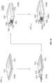
- FIG. 10 is a flow diagram for a method 1000 of assembling an optical engine according to an embodiment of the present disclosure. While FIG. 10 depicts an optical engine 1010 being assembled in accordance with the method 1000, the method 1000 can be utilized to assemble other optical engines, such as any of those disclosed herein.
- the method 1000 can include coupling a PIC with a substrate.
- a PIC 1012 is shown coupled with a substrate 1014.
- the PIC 1012 can be placed atop the substrate 1014, e.g., in a Chip-On-Chip (COC) arrangement.
- COC Chip-On-Chip
- the method 1000 can include coupling a lens array to the PIC.
- a lens array can be coupled with a PIC as set forth below.
- a lens array can be attached to an optical alignment tool.
- a lens array 1016 is shown attached to an optical alignment tool 1018.
- the lens array 1016 can include one or more lenses.
- the optical alignment tool 1018 can include a tool body and one or more optical fibers mated therewith.
- a light source such as a laser, can be housed within the tool body.
- the optical fibers can be used to provide alignment feedback, e.g., when the lens array 1016 is aligned with the PIC 1012.
- the alignment feedback can be provided to a computing system associated with the optical alignment tool 1018.
- the computing system can have one or more non-transitory memory devices and one or more processors, which can be embodied in one or more computing devices.
- the one or more non-transitory memory devices can store instructions that, when executed by the one or more processors, cause the one or more processors to perform operations, such as controlling a robot to adjust alignment of the lens array 1016 relative to the PIC 1012 based at least in part on alignment feedback provided by the optical alignment tool 1018.
- Optical signals can be propagated through the optical fibers of the optical alignment tool 1018 to determine whether such optical signals are propagating optimally through the lens array 1016 to the waveguides of the PIC 1012.
- a robot or robot arm can be adjusted to align the lenses of the lens array 1016 relative to waveguides of the PIC 1012 based at least in part on the alignment feedback provided by the optical alignment tool 1018.
- voice commands or other instructions such as visuals on an augmented reality application, can be provided to a user based at least in part on the alignment feedback provided by the optical alignment tool 1018.
- the alignment feedback indicates that the optical signals pass through the lens array 1016 and to the waveguides of the PIC 1012 with one or more characteristics (e.g., an optical signal intensity, a delay from input to output, an attenuation of the optical signal, a physical alignment of the lenses of the lens array 1016 relative to the waveguides of the PIC 1012, a combination thereof, etc.) within a predetermined range, the one or more conditions can be deemed satisfied. Consequently, the lens array 1016 can be considered aligned with respect to the waveguides of the PIC 1012 and the lens array 1016 can be coupled with the PIC 1012 in the aligned position, e.g., by any suitable technique. After coupling the lens array 1016 to the PIC 1012, the optical alignment tool 1018 can be detached from the lens array 1016.
- the optical alignment tool 1018 can be detached from the lens array 1016.
- the method 1000 can include coupling a lid to the substrate.
- a lid 1020 is shown coupled with the substrate 1014.
- the PIC 1012 is enclosed within the interior defined by the lid 1020 and the substrate 1014.
- the lid 1020 defines an optical feedthrough 1022 configured to fully encircle an optical channel received therein.
- a forward wall 1024 and a lead-in draft 1026 of the lid 1020 define the optical feedthrough 1022.
- the lid 1020 is coupled with the substrate 1014 so that the optical feedthrough 1022 is aligned or in communication with the lens array 1016.
- the lid 1020 can include a coarse alignment feature 1028 (or features) at the optical feedthrough 1022.
- the lead-in draft 1026 of the lid 1020 includes the coarse alignment feature 1028, which includes a top chamfer 1028-1, a bottom chamber 1028-2, and sidewall chamfers 1028-3 (only one of which is labeled in FIG. 10 ).
- the coarse alignment feature 1028 is aligned with the lens array 1016 (when the lens array 1016 is coupled with the PIC 1012).
- the chamfered edges of the lid 1020 can collectively define a perimeter guiding edge along a perimeter of the optical feedthrough 1022 or access opening to the lens array 1016, e.g., as shown in FIG. 10 .
- the lid 1020 in coupling the lid 1020 to the substrate 1014, is arranged relative to the substrate 1014 and the lens array 1016 via feedback from a machine vision system 1030.
- the machine vision system 1030 can include an image device, such as a camera or video camera, and a computing system communicatively coupled thereto.
- the machine vision system 1030 can also include a robot arm that can be controlled to assemble the optical engine 1010.
- the computing system can have one or more non-transitory memory devices and one or more processors, which can be embodied in one or more computing devices.
- the one or more non-transitory memory devices can store instructions that, when executed by the one or more processors, cause the one or more processors to perform operations, such as controlling the robot arm to assemble the lid 1020 relative to the substrate 1014 based at least in part on feedback received from the image device.
- the machine vision system 1030 can also be used to assemble the lens array 1016 relative to the PIC 1012.
- the method 1000 can include curing the lid relative to the substrate.
- the lid 1020 is shown being cured relative to the substrate 1014.
- the lid 1020 can be cured relative to the substrate 1014 in any suitable manner.
- the optical engine 1010 can be considered fully assembled.
- an FAU can be coupled with the PIC as described above instead of the lens array.
- an optical element e.g., a lens array or FAU
Landscapes
- Physics & Mathematics (AREA)
- General Physics & Mathematics (AREA)
- Optics & Photonics (AREA)
- Optical Couplings Of Light Guides (AREA)
Abstract
Description
- Embodiments presented in this disclosure generally relate to opto-electronic devices, and more specifically, to optical engines for opto-electronic apparatuses.
- Opto-electronic apparatuses, such as for Co-Packaged Optical (CPO) and OnBoard Optics (OBO) applications, can include optical engines configured for realizing photoelectric signal conversion. Optical channels, including optical connectors and fiber pigtails, can be optically coupled with such optical engines. Designing access for an optical channel to optically couple with an optical channel has presented certain challenges. For example, access openings for optical engines to receive optical channels have typically been defined by multiple components, which presents certain manufacturing and tolerance stack-up challenges. Thus, there is a need for improved optical channel access to an optical engine.
- So that the manner in which the above-recited features of the present disclosure can be understood in detail, a more particular description of the disclosure, briefly summarized above, may be had by reference to embodiments, some of which are illustrated in the appended drawings. It is to be noted, however, that the appended drawings illustrate typical embodiments and are therefore not to be considered limiting; other equally effective embodiments are contemplated.
-
FIG. 1 is a schematic view of an opto-electronic apparatus according to one or more embodiments of the present disclosure. -
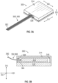
FIG. 2A is a perspective view of an optical engine according to an embodiment of the present disclosure, and depicts an optical feedthrough defined by a lid of the optical engine receiving an optical channel. -
FIG. 2B is a schematic cross-sectional view of the optical engine ofFIG. 2A with the optical channel received by the optical feedthrough. -
FIG. 3A is a perspective view of an optical engine according to another embodiment of the present disclosure, and depicts an optical feedthrough defined by a lid of the optical engine receiving an optical channel. -
FIG. 3B is a schematic cross-sectional view of the optical engine ofFIG. 3A with the optical channel received by the optical feedthrough. -
FIG. 4A is a perspective view of an optical engine according to yet another embodiment of the present disclosure, and depicts an optical channel received by an optical feedthrough defined by a lid of the optical engine. -
FIG. 4B is a perspective view of the optical engine ofFIG. 4A with the lid of the optical engine shown transparent for illustrative purposes. -
FIG. 4C is a schematic cross-sectional view of the optical engine ofFIG. 4A with the optical channel received by the optical feedthrough. -
FIG. 5A is a perspective view of an optical engine according to a further embodiment of the present disclosure, and depicts optical channels received by respective optical feedthroughs defined by a lid of the optical engine. -
FIG. 5B is a perspective view of an optical engine according to a further embodiment of the present disclosure, and depicts optical channels received by respective opposing optical feedthroughs defined by a lid of the optical engine. -
FIG. 5C is a perspective view of an optical engine according to a further embodiment of the present disclosure, and depicts optical channels received by respective neighboring optical feedthroughs defined by a lid of the optical engine. -
FIG. 6A is a perspective view of an optical engine according to another embodiment of the present disclosure, and depicts an optical channel being received by an optical feedthrough defined by a top wall of a lid of the optical engine. -
FIG. 6B is a perspective view of an optical engine according to yet another embodiment of the present disclosure, and depicts an optical channel being received by an optical feedthrough defined by a side wall and a top wall of a lid of the optical engine. -
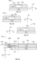
FIG. 7A is a front view of an optical engine according to an additional embodiment of the present disclosure, and depicts an optical feedthrough defined by a lid of the optical engine having a keyway. -
FIG. 7B is a front view of an optical engine according to another embodiment of the present disclosure, and depicts an optical feedthrough defined by a lid of the optical engine having a key. -
FIG. 7C is a front view of an optical engine according to another embodiment of the present disclosure, and depicts an optical feedthrough defined by a lid of the optical engine having an asymmetric key. -
FIG. 7D is a schematic cross-sectional view of an optical engine according to a further embodiment of the present disclosure, and depicts an optical channel received by an optical feedthrough defined by a lid of the optical engine. -
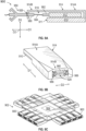
FIG. 8A is a perspective view of an optical engine according to a further embodiment of the present disclosure, and depicts and optical feedthrough defined by a lid that includes two shells, including an optical shell and a thermal shell. -
FIG. 8B is a perspective view of the optical engine ofFIG. 8A , and depicts the optical shell separated from the thermal shell. -
FIG. 9A is a schematic cross-sectional view of an optical engine according to a further embodiment of the present disclosure, and depicts an optical channel received by an optical feedthrough defined by a lid of the optical engine. -
FIG. 9B is a perspective view of the optical engine ofFIG. 9A . -
FIG. 9C is a perspective view of an opto-electronic apparatus that includes a plurality of optical engines configured as inFIGS. 9A and 9B . -
FIG. 10 is a flow diagram for a method of assembling an optical engine according to an embodiment of the present disclosure. - To facilitate understanding, identical reference numerals have been used, where possible, to designate identical elements that are common to the figures. It is contemplated that elements disclosed in one embodiment may be beneficially used in other embodiments without specific recitation.
- One embodiment presented in this disclosure is an optical engine. The optical engine includes a lid defining an optical feedthrough configured to fully encircle an optical channel received therein. The optical engine also includes a PIC covered by the lid and configured to optically couple with the optical channel.
- Another embodiment presented in this disclosure is an opto-electronic apparatus. The opto-electronic apparatus includes an optical channel and at least one optical engine. The at least one optical engine includes a lid defining an optical feedthrough that fully encircles the optical channel received therein. The at least one optical engine also includes a photonic integrated circuit covered by the lid and optically coupled with the optical channel.
- A further embodiment presented in this disclosure is a method. The method includes coupling a photonic integrated circuit (PIC) with a substrate; coupling an optical element with the PIC; and coupling a lid with the substrate so that an optical feedthrough defined by the lid is aligned with the optical element, the optical feedthrough being configured to fully encircle an optical channel received therein.
- Provided herein are various embodiments of optical engines. The optical engines disclosed herein can provide improved access for optical channels to connect thereto. In one example aspect, an optical engine can include a lid defining an optical feedthrough configured to fully encircle at least one optical channel received therein. The optical feedthrough provides an access opening for the optical channel to be fed through so that the optical channel can be coupled with a Photonic Integrated Circuit (PIC) of the optical engine. A method of assembling an optical engine is also provided.
- An optical engine having a lid that defines an optical feedthrough that fully encircles an optical channel received therein can be advantageous for a variety of reasons. For instance, such an arrangement allows for the access opening to the optical engine to be formed by a single component, which can improve the manufacturability of the optical engine and can reduce or eliminate the need to consider the mechanical tolerances between two components to form the optical feedthrough. Moreover, optical engines provided herein can allow for the access opening or optical feedthrough to be made smaller compared conventional designs, which is beneficial for facilitating optical mating between the optical channel and the PIC, and also keeps foreign debris from entering the interior of the optical engine. Further, optical engines provided herein can allow for unique access through a top of the optical engine. Also, optical engines provided herein can include multiple shells forming the lid, enabling the shells to be formed of different materials, which can enhance the optical and thermals aspects of the optical engine. In addition, some optical engines provided herein can include integrated optical and mechanical mating features that, among other benefits, can allow for elimination or reduction of mid-board connectors in embodiments in which such optical engines are incorporated into an opto-electronic apparatus. Furthermore, some optical engines provided herein can include coarse alignment features at the optical feedthrough, which can enhance feedthrough of an optical channel through or into the optical feedthrough. Other benefits, advantages, and technical effects associated with the disclosed optical engines other than those expressly listed are possible. Example embodiments of optical engines that can achieve one or more of the noted benefits and/or advantages are provided below.
-
FIG. 1 is a schematic view of an opto-electronic apparatus 100 according to one or more embodiments. InFIG. 1 , the opto-electronic apparatus 100 is configured as a Co-Packaged Optical (CPO) system, or CPO system. As shown, the opto-electronic apparatus 100 includes, among other components, asubstrate 110, an electronic integrated circuit (IC) 112, and one or more optical engines 114-1 through 114-8 (generically or collectively, optical engine(s) 114). Theelectronic IC 112 is centrally located on thesubstrate 110 and theoptical engines 114 are arranged laterally outward from theelectronic IC 112. Other arrangements of theelectronic IC 112 and theoptical engines 114 are also contemplated. Theelectronic IC 112 and theoptical engines 114 can have any suitable functionality. Theelectronic IC 112 can be a Network Processor Unit (NPU), for example. Theoptical engines 114 can be configured for realizing photoelectric signal conversion. Afaceplate 116 is coupled with thesubstrate 110. Thefaceplate 116 can provide a pluggable interface with the opto-electronic apparatus 100. - In some embodiments, the
substrate 110 conductively couples theelectronic IC 112 and theoptical engines 114. Particularly, thesubstrate 110 can include one or more layers, such as conductive layer(s), semiconductor layer(s), and/or insulator layer(s). Thesubstrate 110 can further include one or more conductive vias extending between layers, and/or extending to a top surface and/or a bottom surface of thesubstrate 110. For instance, thesubstrate 110 can include first conductive connections on a top surface of thesubstrate 110, second conductive connections on a bottom surface of thesubstrate 110, and conductive vias connecting the first and second conductive connections. In this way, theelectronic IC 112 and theoptical engines 114 can be mounted on the top surface and connected through thesubstrate 110 to a printed circuit board (PCB) or other device connected to the bottom surface. - In addition, the opto-
electronic apparatus 100 includes one or more light sources. For the depicted embodiment ofFIG. 1 , the opto-electronic apparatus 100 includes a plurality of remote light sources (RLS) 118-1, 118-2, 118-3 (generically or collectively, RLS(s) 118). In some embodiments, theRLS 118 can be lasers and can be either single- or multi-wavelength light sources. RLS 118-1, 118-2, 118-3 are disposed within respective light source enclosures 120-1, 120-2, 120-3. - The opto-
electronic apparatus 100 further includes connectors and one or more optical fibers. For the illustrated embodiment ofFIG. 1 , the opto-electronic apparatus 100 includes a plurality of optical connectors (generically or collectively, optical connector(s) 122) and a plurality of optical fibers (generically or collectively, optical fiber(s) 124). The optical connectors 122 include a set of optical engine connectors 122-1 (not all of which are labeled) each configured to optically couple with one of theoptical engines 114, a set of mid-board optical connectors 122-2 that optically couple one optical fiber with another, a set of faceplate optical connectors 122-3 that each offer optical coupling at thefaceplate 116, and a set of RLS optical connectors 122-4 each configured to optically couple with one of theRLS 118. The optical fibers 124 (not all of which are labeled inFIG. 1 ) can carry optical signals, e.g., from one of theRLS 118 to a Photonics Integrated Circuit (PIC) of one of theoptical engines 114. - In accordance with inventive aspects of the present disclosure, one or more of the
optical engines 114 of the opto-electronic apparatus 100 can include a lid that defines an optical feedthrough configured to fully encircle an optical channel received therein. The optical feedthroughs provide access openings for respective optical channels to be fed therethrough. For the example embodiment ofFIG. 1 , eachoptical engine 114 has a lid defining an optical feedthrough. Optical engines 114-2, 114-5, 114-7 are each shown with an optical engine connector 122-1 fed through their respective optical feedthroughs (as represented by the dashed lines). Various example embodiments detailing such inventive aspects are provided below. - With reference now to
FIGS. 2A and 2B , anoptical engine 200 according to one embodiment of the present disclosure is disclosed.FIG. 2A is a perspective view of theoptical engine 200, and also depicts an optical channel 250.FIG. 2B is a schematic cross-sectional view of theoptical engine 200 receiving the optical channel 250. Theoptical engine 200 can be implemented in an opto-electronic apparatus, such as the opto-electronic apparatus 100 ofFIG. 1 . - As shown, the
optical engine 200 includes asubstrate 210, aPIC 212, and alid 214. ThePIC 212 is disposed on thesubstrate 210 and can include one or more waveguides. ThePIC 212 optically couples with the optical channel 250. Thelid 214 and thesubstrate 210 collectively enclose thePIC 212, e.g., within an interior 216. ThePIC 212 is covered by thelid 214. Thelid 214 includes atop wall 218 and a plurality of sidewalls, including aforward wall 220, arear wall 222, afirst side wall 224, and asecond side wall 226. Theforward wall 220 and therear wall 222 are spaced from one another, e.g., along a first direction D1. Thefirst side wall 224 and thesecond side wall 226 are spaced from one another, e.g., along a second direction D2. Thefirst side wall 224 and thesecond side wall 226 extend between and connect theforward wall 220 and therear wall 222. Theforward wall 220, therear wall 222, thefirst side wall 224, and thesecond side wall 226 each connect to thetop wall 218 and extend, e.g., along a third direction D3, which is a vertical direction in this example embodiment. The first direction D1, the second direction D2, and the third direction D3 are mutually perpendicular and form an orthogonal direction system. - Further, for the depicted embodiment of
FIGS. 2A and 2B , the optical channel 250 is configured as an optical connector 260. The optical connector 260 includes anoptical fiber 262, anoptical ferrule 264, aspring 266 or biasing member, and anexternal connector housing 268. Theoptical ferrule 264 is optically coupled with theoptical fiber 262. Aflange 270 can couple theoptical ferrule 264 with thespring 266. Thespring 266 functions to bias theoptical ferrule 264 in position relative to the mating interface on thePIC 212 or other optical element. Theexternal connector housing 268 can mechanically couple to a structure, such as a load plate or stiffener (not shown), via one ormore latches 272 of theexternal connector housing 268. - As further shown in
FIGS. 2A and 2B , thelid 214 of theoptical engine 200 defines anoptical feedthrough 228 that is configured to fully encircle the optical channel 250 received therein, e.g., as shown inFIG. 2B . In this regard, theoptical feedthrough 228 provides an access opening for the optical channel 250 to be fed through so that the optical channel 250 can be coupled with thePIC 212 of theoptical engine 200, or more specifically, so that theoptical ferrule 264 can be optically coupled with thePIC 212, either directly or indirectly. In this regard, optical signals can traverse between theoptical fiber 262 and thePIC 212 by way of theoptical ferrule 264. In this example embodiment, theoptical ferrule 264 is fed through theoptical feedthrough 228 while thespring 266 andexternal connector housing 268 remain external to theinterior 216 of theoptical engine 200. As noted above, theexternal connector housing 268 can mechanically couple to a structure to maintain theoptical ferrule 264 in position relative to thePIC 212. - Further, in this example embodiment, the
forward wall 220 defines theoptical feedthrough 228. However, as will be disclosed further herein, in alternative example embodiments, other wall(s) of thelid 214 can define theoptical feedthrough 228. Theoptical feedthrough 228 has a rectangular shape with rounded corners in this example embodiment, but other shapes are possible. InFIG. 2A , theoptical feedthrough 228 is sized to accommodate theoptical ferrule 264 of the optical connector 260, but other sizes are possible. - Advantageously, the
optical feedthrough 228, which is configured to fully encircle the optical channel 250 received therein, defined by thelid 214 allows for the access opening to be made smaller compared conventional designs, which is beneficial for facilitating optical mating of theoptical ferrule 264 and thePIC 212 or waveguides thereof and also for keeping foreign debris from entering theinterior 216 of theoptical engine 200. Moreover, theoptical feedthrough 228 being defined by thelid 214, and only thelid 214, can improve manufacturing efficiency as theoptical feedthrough 228 need only be formed in a single component (i.e., the lid 214). In addition, theoptical feedthrough 228 being defined by a single component (i.e., the lid 214) can reduce or eliminate the need to consider the mechanical tolerances between two components to form theoptical feedthrough 228, as in conventional designs. - In some further embodiments, an optical channel received or fed through an optical feedthrough defined by a lid of an optical engine can be a fiber pigtail. By way of example, with reference now to
FIGS. 3A and 3B, FIG. 3A is a perspective view of anoptical engine 300, and depicts anoptical feedthrough 328 defined by alid 314 of theoptical engine 300 receiving an optical channel 350.FIG. 3B is a schematic cross-sectional view of theoptical engine 300 with the optical channel 350 fed through or received by theoptical feedthrough 328. Theoptical engine 300 is configured in a similar manner as theoptical engine 200 ofFIGS. 2A and 2B and thus will not be described in detail for the sake of brevity. - The optical channel 350, as noted above, is configured as a fiber pigtail 360. The fiber pigtail 360 includes an optical fiber 362 (or fibers) that are fed through the
optical feedthrough 328 of thelid 314 and are permanently coupled with aPIC 312 of theoptical engine 300 via a Fiber Array Unit (FAU), orFAU 364. TheFAU 364 is disposed within an interior 316 of theoptical engine 300 defined by thelid 314 and asubstrate 310, and is optically coupled with thePIC 312. In some embodiments, theFAU 364 is positioned, at least in part, within theoptical feedthrough 328. In other embodiments, theFAU 364 can be positioned entirely within the interior 316, or rather, not positioned in part within theoptical feedthrough 328. - The
optical feedthrough 328 has a rectangular shape with rounded corners in this example embodiment, but other shapes are possible. Theoptical feedthrough 328 is sized to accommodate theFAU 364, but other sizes are possible. - In yet other embodiments of the present disclosure, an optical engine can include a lid extension. In such embodiments, the lid of an optical engine can extend beyond the substrate/package outline for extra working distance and material volume. This may allow for, among other benefits, the mechanical latching mechanism of an optical connector to latch to the lid rather than another structure.
- By way of example, with reference now to
FIGS. 4A, 4B, and 4C, FIG. 4A is a perspective view of anoptical engine 400, and depicts an optical channel 450 received by anoptical feedthrough 428 defined by alid 414 of theoptical engine 400.FIG. 4B is a perspective view of theoptical engine 400 with thelid 414 of theoptical engine 400 shown transparent for illustrative purposes.FIG. 4C is a schematic cross-sectional view of theoptical engine 400 with the optical channel 450 received by theoptical feedthrough 428. - As shown, the
lid 414 has alid extension 414B that extends beyond aforward edge 411 of asubstrate 410 of theoptical engine 400. In this regard, thelid 414 extends beyond an outline of thesubstrate 410, e.g., along the first direction D1. Thelid extension 414B can extend from alid base 414A. Thelid extension 414B is defined as the portion of thelid 414 that extends beyond theforward edge 411 of thesubstrate 410 and thelid base 414A is defined as the portion of thelid 414 that extends rearward of theforward edge 411 of thesubstrate 410 along the first direction D1. Thelid base 414A generally covers aPIC 412 and thesubstrate 410. Thelid base 414A and thelid extension 414B can be formed as a unitary or single-piece, monolithic component. - In some embodiments, the
lid extension 414B extends along the first direction D1 a length L1 that is at least a quarter of a length L2 of thesubstrate 410. In some embodiments, thelid extension 414B extends along the first direction D1 so as to be operable to accommodate anoptical ferrule 464 and aspring 466 of the optical channel 450, e.g., as shown best inFIG. 4B . That is, theoptical ferrule 464 and thespring 466 can be fed through theoptical feedthrough 428, which is defined by thelid extension 414B in this example embodiment, and can be accommodated within an interior 416 of theoptical engine 400. Theoptical ferrule 464 is optically coupled with an optical fiber 462 (or fibers). An externaloptical connector housing 468 can be positioned, at least in part, within theoptical feedthrough 428. The externaloptical connector housing 468 can be latched to thelid 414, or rather, thelid extension 414B. The optical channel 450 is configured as an optical connector 460 in this embodiment, which is configured in a similar manner as the optical channel 250 ofFIGS. 2A and 2B . - In yet further embodiments, the
lid extension 414B can define a look-through 415 that allows for visibility of an optical interface where theoptical ferrule 464 interfaces with thePIC 412 or optical component thereof. The look-through 415 can be defined as an opening in thelid 414, e.g., as shown inFIG. 4A , or can be configured as a window, e.g., formed of glass. The look-through 415 can provide a means to view the optical interface, which may be beneficial to ensure the optical connector 460 has been properly fed through theoptical feedthrough 428 with theoptical ferrule 464 positioned in place relative to thePIC 412 or other optical component (e.g., a lens array). - In some further embodiments of the present disclosure, a lid of an optical engine can define two or more optical feedthroughs to accommodate multiple optical channels. Accordingly, in such embodiments, a lid of an optical engine can define a plurality of optical feedthroughs that can receive respective optical channels. Such embodiments can be useful for Onboard Optics (OBO) applications.
- As one example,
FIG. 5A is a perspective view of anoptical engine 500A having alid 514A that defines multiple optical feedthroughs. Thelid 514A is coupled with asubstrate 510A and together thelid 514A and thesubstrate 510A enclose a PIC. InFIG. 5A , the plurality of optical feedthroughs defined by thelid 514A include a firstoptical feedthrough 528A-1 and a secondoptical feedthrough 528A-2 defined by a same sidewall of thelid 514A, which in this example embodiment is aforward wall 520A. The first and secondoptical feedthroughs 528A-1, 528A-2 are each configured to receive respectiveoptical channels 550A-1, 550A-2, which are both configured in a similar manner as the optical channel 250 ofFIGS. 2A, 2B . - In some embodiments, an optical feedthrough defined by a lid can be defined by a sidewall and a lead-draft extending from a wall of the lid. For example, as further shown in
FIG. 5A , thelid 514A has a first lead-indraft 530A-1 that extends outward (a direction opposite of the interior of theoptical engine 500A) from theforward wall 520A. Theforward wall 520A and the first lead-indraft 530A-1 collectively define the firstoptical feedthrough 528A-1. Thelid 514A also has a second lead-indraft 530A-2 that extends outward from theforward wall 520A. The second lead-indraft 530A-2 is spaced from the first lead-indraft 530A-1, e.g., along the second direction D2. Theforward wall 520A and the second lead-indraft 530A-2 collectively define the secondoptical feedthrough 528A-2. The lead-indrafts 530A-1, 530A-2 can facilitate feedthrough of theoptical channels 550A-1, 550A-2 through their respectiveoptical feedthroughs 528A-1, 528-2. - As a second example,
FIG. 5B is a perspective view of anoptical engine 500B having alid 514B that defines multiple optical feedthroughs. Thelid 514B is coupled with asubstrate 510B and together thelid 514B and thesubstrate 510B enclose a PIC. InFIG. 5B , the plurality of optical feedthroughs defined by thelid 514B include a firstoptical feedthrough 528B-1 and a secondoptical feedthrough 528B-2 defined by opposing sidewalls of thelid 514B. In this example embodiment, the opposing sidewalls include theforward wall 520B and therear wall 522B. The firstoptical feedthrough 528B-1 is defined by theforward wall 520B (and in part by a lead-in draft) and the secondoptical feedthrough 528B-2 is defined by therear wall 522B (and in part by a lead-in draft). The first and secondoptical feedthroughs 528B-1, 528B-2 are each configured to receive respectiveoptical channels 550B-1, 550B-2, which are both configured in a similar manner as the optical channel 250 ofFIGS. 2A, 2B . - As a third example,
FIG. 5C is a perspective view of anoptical engine 500C having alid 514C that defines multiple optical feedthroughs. Thelid 514C is coupled with asubstrate 510C and together thelid 514C and thesubstrate 510C enclose a PIC. InFIG. 5C , the plurality of optical feedthroughs defined by thelid 514C include a firstoptical feedthrough 528C-1 and a secondoptical feedthrough 528C-2 defined by adjacent or neighboring sidewalls of thelid 514C. In this example embodiment, the neighboring sidewalls include theforward wall 520C and thefirst side wall 524C. The firstoptical feedthrough 528C-1 is defined by theforward wall 520C (and in part by a lead-in draft) and the secondoptical feedthrough 528C-2 is defined by thefirst side wall 524C (and in part by a lead-in draft). The first and secondoptical feedthroughs 528C-1, 528C-2 are each configured to receive respectiveoptical channels 550C-1, 550C-2, which are both configured in a similar manner as the optical channel 250 ofFIGS. 2A, 2B . - In some further embodiments of the present disclosure, a horizontally-oriented wall (e.g., a top wall) of a lid of an optical engine can define, at least in part, an optical feedthrough configured to fully encircle an optical channel received therein.
- As one example,
FIG. 6A is a perspective view of anoptical engine 600A. Theoptical engine 600A has alid 614A that is coupled with asubstrate 610A. Thelid 614A and thesubstrate 610A collectively enclose a PIC. InFIG. 6A , atop wall 618A of thelid 614A defines anoptical feedthrough 628A configured to fully encircle anoptical channel 650A received therein. Theoptical channel 650A can be a pigtail or connector application. - As another example,
FIG. 6B is a perspective view of anoptical engine 600B. Theoptical engine 600B has alid 614B that is coupled with asubstrate 610B. Thelid 614B and thesubstrate 610B collectively enclose a PIC. InFIG. 6B , a horizontally-oriented wall (e.g., atop wall 618B) and a vertically-oriented wall (e.g., aforward wall 620B) collectively define anoptical feedthrough 628B configured to fully encircle anoptical channel 650B received therein. Theoptical channel 650B can be a pigtail or connector application. - An optical feedthrough defined, at least in part, by a top wall of a lid, e.g., as shown in
FIGS. 6A and 6B , can provide enhanced access to connect an optical channel to an optical engine in some applications, or for installation purposes in the case of a pigtail optical channel. An optical feedthrough defined by both a sidewall and a top wall of the lid can be particularly useful as such an optical feedthrough accommodates insertion or feedthrough of an optical channel from both a vertical and horizontal perspective. - In some further embodiments of the present disclosure, an optical feedthrough defined by a lid of an optical engine can include a feature (or features) that facilitates feedthrough or insertion of an optical channel therethrough.
- As one example,
FIG. 7A is a front view of anoptical engine 700A. Theoptical engine 700A has alid 714A coupled with asubstrate 710A. Thelid 714A defines anoptical feedthrough 728A configured to fully encircle an optical channel received therein. Theoptical feedthrough 728A is defined by thelid 714A so that theoptical feedthrough 728A has afeedthrough region 732A and akeyway 734A (demarcated by a dashed line inFIG. 7A ) contiguous with thefeedthrough region 732A. Thekeyway 734A can accommodate or receive a complementary key of an optical connector fed through or into theoptical feedthrough 728A. In this way, thekeyway 734A can facilitate or correct a feedthrough orientation of an optical channel through theoptical feedthrough 728A. - As another example,
FIG. 7B is a front view of anoptical engine 700B. Theoptical engine 700B has alid 714B coupled with asubstrate 710B. Thelid 714B defines anoptical feedthrough 728B configured to fully encircle an optical channel received therein. In this example embodiment, thelid 714B has a key 736B that extends into theoptical feedthrough 728B. The key 736B can be received or accommodated by a complementary keyway of an optical connector fed through or into theoptical feedthrough 728B. In this way, the key 736B can facilitate or correct a feedthrough orientation of an optical channel through theoptical feedthrough 728B. - As yet another example,
FIG. 7C is a front view of anoptical engine 700C. Theoptical engine 700C has alid 714C coupled with asubstrate 710C. Thelid 714C defines anoptical feedthrough 728C configured to fully encircle an optical channel received therein. In this example embodiment, theoptical feedthrough 728C defined by thelid 714C has an asymmetric shape as viewed along a feedthrough direction (e.g., the first direction D1 in this example embodiment). Advantageously, the asymmetric shape of theoptical feedthrough 728C can facilitate or correct a feedthrough orientation of an optical channel through theoptical feedthrough 728C. -
FIG. 7D is a schematic cross-sectional view of anoptical engine 700D. Theoptical engine 700D has alid 714D coupled with asubstrate 710D. Thelid 714D and thesubstrate 710D collectively enclose aPIC 712D, e.g., within an interior 716D of theoptical engine 700D. Like the embodiment ofFIGS. 4A, 4B, and 4C , thelid 714D has alid extension 714D-2 extending beyond aforward edge 711D of thesubstrate 710D. Thelid extension 714D-2 extends from alid base 714D-1. Thelid base 714D-1 and thelid extension 714D-2 can be formed as a unitary or single-piece, monolithic component. - For the depicted embodiment of
FIG. 7D , thelid 714D, or more particularly, thelid extension 714D-2 defines anoptical feedthrough 728D configured to fully encircle anoptical channel 750D received therein. In this example embodiment, thelid extension 714D-2 defines theoptical feedthrough 728D so that theoptical feedthrough 728D includes anexternal access region 728D-1 and aninternal region 728D-2 that is contiguous with theexternal access region 728D-1. Theinternal region 728D-2 has a countersink shape as viewed along the second direction D2. The unique arrangement of theexternal access region 728D-1 and theinternal region 728D-2 allows for mechanical latching mechanisms of theoptical channel 750D to mechanically engage thelid 714D at a mechanical reference plane MRP, which is at an internal position relative to aforward surface 715D of thelid 714D. With the lid mechanically engaged, a force can be applied (e.g., by a spring of theoptical channel 750D) to keep the optical facets (e.g., an optical ferrule of theoptical channel 750D and thePIC 712D) aligned in optical engagement at an optical reference plane ORP. The mechanical reference plane separates theexternal access region 728D-1 from theinternal region 728D-2 along the first direction D1 in this example embodiment. - In some embodiments of the present disclosure, an optical engine can include a lid formed of at least two shells, wherein one (or more) of the shells defines an optical feedthrough through which an optical channel can be fed.
- By way of example, with reference now to
FIGS. 8A and 8B , anoptical engine 800 is depicted. Theoptical engine 800 has alid 814 coupled with asubstrate 810. Thelid 814 and thesubstrate 810 collectively enclose aPIC 812. For the depicted example embodiment, thelid 814 has anoptical shell 814A and athermal shell 814B that are removably coupled by aninterlock 838, and as shown, theoptical feedthrough 828 is defined by theoptical shell 814A. Theoptical feedthrough 828 is configured to fully encircle an optical channel received therein. In some embodiments, theoptical shell 814A and thethermal shell 814B can be formed of different materials. For instance, thethermal shell 814B can be formed of a conductive metal material and theoptical shell 814A can be formed of a plastic material, for example. - The
interlock 838 can be formed by complementary features of theoptical shell 814A and thethermal shell 814B. As shown inFIG. 8B , the features of thethermal shell 814B forming theinterlock 838 include atongue 840 that extends from atop wall 818B of thethermal shell 814B and alap member 842. Thetongue 840 is an extension of thetop wall 818B and thelap member 842 has a cross member connected to sidewalls at each end. The sidewalls of thelap member 842 are positioned inward of thefirst side wall 824B and thesecond side wall 826B of thethermal shell 814B, e.g., along the second direction D2. The feature of theoptical shell 814A forming theinterlock 838 is agroove 844 that receives thetongue 840 of thethermal shell 814B as well as thelap member 842. Thegroove 844 is formed by an interior surface of atop wall 818A of theoptical shell 814A. When locked together, a portion of thetop wall 818A of theoptical shell 814A can be seated on thelap member 842 of thethermal shell 814B. In alternative embodiments, other suitable mechanical interlocks can be used, including a dovetail interlock, for example. - Advantageously, the
lid 814 formed by two shells can allow for an "optical lid" or shell for optical feedthrough and a "thermal lid" or shell for heat management. An interlocking mechanism can be used to combine the shells and to secure them in place whilst also providing enhanced ability to access the interior of the optical engine if needed. Different materials can be used for the shells, which can provide localized optimization of material properties to enhance the optical and thermal aspects of theoptical engine 800. - In some further embodiments of the present disclosure, an optical engine can include integrated features that complement an optical feedthrough defined by a lid of the optical engine. In such embodiments, for example, an optical engine can include a lid defining an optical feedthrough in which integrated features are positioned, including a Mechanical Transferrable (MT) ferrule and mechanical mating features, such as Multifiber Push On (MPO) mating features. Such features can provide an optical and mechanical interface at the optical feedthrough.
- By way of example, with reference now to
FIGS. 9A and 9B anoptical engine 900 is depicted. Theoptical engine 900 has alid 914 coupled with asubstrate 910. Thelid 914 and thesubstrate 910 collectively enclose aPIC 912, e.g., within an interior 916 of theoptical engine 900. Like the embodiment ofFIGS. 4A, 4B, and 4C , thelid 914 has alid extension 914B extending beyond aforward edge 911 of thesubstrate 910. Thelid extension 914B extends from alid base 414A. Thelid base 914A and thelid extension 914B can be formed as a unitary or single-piece, monolithic component. - For the depicted embodiment of
FIGS. 9A and 9B , theoptical engine 900 includes anMT ferrule 980 integrated into thelid extension 414B. TheMT ferrule 980 can be optically coupled with anFAU 982 that is optically coupled with thePIC 912. Afiber pigtail 984 can optically couple theMT ferrule 980 with theFAU 982. Thelid extension 414B can define theoptical feedthrough 928. TheMT ferrule 980 can be positioned, at least in part, in theoptical feedthrough 928. A portion of theMT ferrule 980 can be positioned within theinterior 916. InFIG. 9A , anoptical channel 950 is coupled with theMT ferrule 980. - The
optical engine 900 can also include mating features, such as MPO mating features. As illustrated, retention posts 986 are positioned on opposing sides of theMT ferrule 980. The retention posts 986 are each movable between a neutral position and a biased position. For instance, when no optical connector is connected to theMT ferrule 980, e.g., as shown inFIG. 9B , the retention posts 986 are each in their respective neutral positions. When an optical connector is connected to theMT ferrule 980, the retention posts 986 can each be deflected (e.g., outward away from theMT ferrule 980 in opposing directions along the second direction D2) and moved into their respective biased positions. In their respective biased positions, the retention posts 986 contact the optical connector with biasing engagement, which retains the optical connector relative to theMT ferrule 980 and theoptical engine 900 generally. The retention posts 986, or mechanical mating features, can be positioned, at least in part, within theoptical feedthrough 928, e.g., as shown inFIG. 9B . -
FIG. 9C is a perspective view of an opto-electronic apparatus 902 that includes a plurality ofoptical engines 900 configured as inFIGS. 9A and 9B . The opto-electronic apparatus 902 includes anelectronic IC 904, which can be an NPU, for example. Theoptical engines 900 can be arranged about theelectronic IC 904 as shown inFIG. 9C . Advantageously, due to the integrated nature of theoptical engines 900 as disclosed above, opto-electronic apparatus 902 ofFIG. 9C can allow for elimination of one or more mid-board optical connectors (seeFIG. 1 showing mid-board optical connectors 122-2). -
FIG. 10 is a flow diagram for amethod 1000 of assembling an optical engine according to an embodiment of the present disclosure. WhileFIG. 10 depicts anoptical engine 1010 being assembled in accordance with themethod 1000, themethod 1000 can be utilized to assemble other optical engines, such as any of those disclosed herein. - At 1002, the
method 1000 can include coupling a PIC with a substrate. For instance, inFIG. 10 , aPIC 1012 is shown coupled with asubstrate 1014. ThePIC 1012 can be placed atop thesubstrate 1014, e.g., in a Chip-On-Chip (COC) arrangement. - At 1004, the
method 1000 can include coupling a lens array to the PIC. A lens array can be coupled with a PIC as set forth below. - A lens array can be attached to an optical alignment tool. For instance, as shown in
FIG. 10 , alens array 1016 is shown attached to anoptical alignment tool 1018. Thelens array 1016 can include one or more lenses. Theoptical alignment tool 1018 can include a tool body and one or more optical fibers mated therewith. A light source, such as a laser, can be housed within the tool body. The optical fibers can be used to provide alignment feedback, e.g., when thelens array 1016 is aligned with thePIC 1012. The alignment feedback can be provided to a computing system associated with theoptical alignment tool 1018. The computing system can have one or more non-transitory memory devices and one or more processors, which can be embodied in one or more computing devices. The one or more non-transitory memory devices can store instructions that, when executed by the one or more processors, cause the one or more processors to perform operations, such as controlling a robot to adjust alignment of thelens array 1016 relative to thePIC 1012 based at least in part on alignment feedback provided by theoptical alignment tool 1018. Optical signals can be propagated through the optical fibers of theoptical alignment tool 1018 to determine whether such optical signals are propagating optimally through thelens array 1016 to the waveguides of thePIC 1012. In some implementations, a robot or robot arm can be adjusted to align the lenses of thelens array 1016 relative to waveguides of thePIC 1012 based at least in part on the alignment feedback provided by theoptical alignment tool 1018. In other implementations, voice commands or other instructions, such as visuals on an augmented reality application, can be provided to a user based at least in part on the alignment feedback provided by theoptical alignment tool 1018. - When the alignment feedback indicates that the optical signals pass through the
lens array 1016 and to the waveguides of thePIC 1012 with one or more characteristics (e.g., an optical signal intensity, a delay from input to output, an attenuation of the optical signal, a physical alignment of the lenses of thelens array 1016 relative to the waveguides of thePIC 1012, a combination thereof, etc.) within a predetermined range, the one or more conditions can be deemed satisfied. Consequently, thelens array 1016 can be considered aligned with respect to the waveguides of thePIC 1012 and thelens array 1016 can be coupled with thePIC 1012 in the aligned position, e.g., by any suitable technique. After coupling thelens array 1016 to thePIC 1012, theoptical alignment tool 1018 can be detached from thelens array 1016. - At 1006, the
method 1000 can include coupling a lid to the substrate. For instance, as illustrated inFIG. 10 at 1006, alid 1020 is shown coupled with thesubstrate 1014. In this regard, thePIC 1012 is enclosed within the interior defined by thelid 1020 and thesubstrate 1014. Thelid 1020 defines anoptical feedthrough 1022 configured to fully encircle an optical channel received therein. In this example, aforward wall 1024 and a lead-in draft 1026 of thelid 1020 define theoptical feedthrough 1022. Thelid 1020 is coupled with thesubstrate 1014 so that theoptical feedthrough 1022 is aligned or in communication with thelens array 1016. - In some implementations, the
lid 1020 can include a coarse alignment feature 1028 (or features) at theoptical feedthrough 1022. InFIG. 10 , the lead-in draft 1026 of thelid 1020 includes thecoarse alignment feature 1028, which includes a top chamfer 1028-1, a bottom chamber 1028-2, and sidewall chamfers 1028-3 (only one of which is labeled inFIG. 10 ). Thecoarse alignment feature 1028 is aligned with the lens array 1016 (when thelens array 1016 is coupled with the PIC 1012). The chamfered edges of thelid 1020 can collectively define a perimeter guiding edge along a perimeter of theoptical feedthrough 1022 or access opening to thelens array 1016, e.g., as shown inFIG. 10 . - In some implementations, in coupling the
lid 1020 to thesubstrate 1014, thelid 1020 is arranged relative to thesubstrate 1014 and thelens array 1016 via feedback from amachine vision system 1030. Themachine vision system 1030 can include an image device, such as a camera or video camera, and a computing system communicatively coupled thereto. Themachine vision system 1030 can also include a robot arm that can be controlled to assemble theoptical engine 1010. The computing system can have one or more non-transitory memory devices and one or more processors, which can be embodied in one or more computing devices. The one or more non-transitory memory devices can store instructions that, when executed by the one or more processors, cause the one or more processors to perform operations, such as controlling the robot arm to assemble thelid 1020 relative to thesubstrate 1014 based at least in part on feedback received from the image device. In some implementations, themachine vision system 1030 can also be used to assemble thelens array 1016 relative to thePIC 1012. - At 1008, the
method 1000 can include curing the lid relative to the substrate. For instance, as shown inFIG. 10 at 1008, thelid 1020 is shown being cured relative to thesubstrate 1014. Thelid 1020 can be cured relative to thesubstrate 1014 in any suitable manner. After cure, theoptical engine 1010 can be considered fully assembled. In alternative implementations, an FAU can be coupled with the PIC as described above instead of the lens array. In this regard, an optical element (e.g., a lens array or FAU) can be coupled with the PIC in accordance with themethod 1000. - In the current disclosure, reference is made to various embodiments. However, the scope of the present disclosure is not limited to specific described embodiments. Instead, any combination of the described features and elements, whether related to different embodiments or not, is contemplated to implement and practice contemplated embodiments. Additionally, when elements of the embodiments are described in the form of "at least one of A and B," or "at least one of A or B," it will be understood that embodiments including element A exclusively, including element B exclusively, and including element A and B are each contemplated. Furthermore, although some embodiments disclosed herein may achieve advantages over other possible solutions or over the prior art, whether or not a particular advantage is achieved by a given embodiment is not limiting of the scope of the present disclosure. Thus, the aspects, features, embodiments and advantages disclosed herein are merely illustrative and are not considered elements or limitations of the appended claims except where explicitly recited in a claim(s). Likewise, reference to "the invention" shall not be construed as a generalization of any inventive subject matter disclosed herein and shall not be considered to be an element or limitation of the appended claims except where explicitly recited in a claim(s).
- In view of the foregoing, the scope of the present disclosure is determined by the claims that follow.
Claims (15)
- An optical engine, comprising:a lid defining an optical feedthrough configured to fully encircle an optical channel received therein; anda photonics integrated circuit (PIC) covered by the lid and configured to optically couple with the optical channel.
- The optical engine of claim 1, further comprising:a substrate, wherein the PIC is disposed on the substrate and the lid contacts the substrate, wherein the lid and the substrate collectively enclose the PIC, andwherein the lid has a lid extension extending beyond a forward edge of the substrate, the lid extension defines the optical feedthrough.
- The optical engine of claim 2, wherein the optical engine defines a first direction, and wherein the lid extension extends along the first direction a length that is at least a quarter of a length of the substrate that extends along the first direction.
- The optical engine of claim 2 or 3, wherein the optical engine defines a feedthrough direction, and wherein the lid extension extends along the feedthrough direction so as to be operable to accommodate an optical ferrule and a spring of the optical channel.
- The optical engine of any of claims 2 to 4, wherein the lid extension defines a look-through that allows for visibility of an optical interface where an optical ferrule of the optical channel interfaces with the PIC or an optical component coupled with the PIC.
- The optical engine of any preceding claim, wherein the lid has a sidewall that defines the optical feedthrough.
- The optical engine of any preceding claim, wherein one or more of:A) the lid has a sidewall and a lead-in draft that extends from the sidewall, the sidewall and the lead-in draft collectively define the optical feedthrough;B) the optical feedthrough has a feedthrough region and a keyway contiguous with the feedthrough region;C) the lid has a key that extends into the optical feedthrough;D) the optical feedthrough has an asymmetric shape as viewed along a feedthrough direction of the optical channel;E) the lid has a top wall, and wherein the optical feedthrough is defined by the top wall;F) the lid has a sidewall and a top wall, and wherein the optical feedthrough is defined collectively by the sidewall and the top wall.
- The optical engine of any preceding claim, wherein the optical feedthrough is one of a plurality of optical feedthroughs defined by the lid, and wherein the plurality of optical feedthroughs of the lid include a first optical feedthrough and a second optical feedthrough defined by a same sidewall of the lid.
- The optical engine of any preceding claim, wherein the optical feedthrough is one of a plurality of optical feedthroughs defined by the lid, and wherein the plurality of optical feedthroughs of the lid include a first optical feedthrough and a second optical feedthrough, the first optical feedthrough and the second optical feedthrough are defined by different sidewalls of the lid.
- The optical engine of any preceding claim, wherein the lid has an optical shell and a thermal shell that are removably coupled with one another, the optical feedthrough is defined by the optical shell.
- The optical engine of claim 10, wherein the optical shell and the thermal shell are formed of different materials.
- The optical engine of any preceding claim, further comprising:a substrate, and wherein the lid has a lid extension extending beyond a forward edge of the substrate; anda mechanically transferrable (MT) ferrule integrated into the lid extension and optically coupled with a fiber array unit that is optically coupled with the PIC, the MT ferrule is positioned at least in part within the optical feedthrough.
- The optical engine of any preceding claim, wherein the lid has a coarse alignment feature that includes one or more chamfered edges at the optical feedthrough.
- An opto-electronic apparatus, comprising:an optical channel; andat least one optical engine, comprising:a lid defining an optical feedthrough that fully encircles the optical channel received therein; anda photonic integrated circuit covered by the lid and optically coupled with the optical channel.
- A method, comprising:coupling a photonic integrated circuit (PIC) with a substrate;coupling an optical element with the PIC; andcoupling a lid with the substrate so that an optical feedthrough defined by the lid is aligned with the optical element, the optical feedthrough being configured to fully encircle an optical channel received therein.
Applications Claiming Priority (1)
| Application Number | Priority Date | Filing Date | Title |
|---|---|---|---|
| US18/487,623 US20250123451A1 (en) | 2023-10-16 | 2023-10-16 | Optical engine lid with optical feedthrough |
Publications (2)
| Publication Number | Publication Date |
|---|---|
| EP4553551A2 true EP4553551A2 (en) | 2025-05-14 |
| EP4553551A3 EP4553551A3 (en) | 2025-09-03 |
Family
ID=93150268
Family Applications (1)
| Application Number | Title | Priority Date | Filing Date |
|---|---|---|---|
| EP24206804.7A Pending EP4553551A3 (en) | 2023-10-16 | 2024-10-16 | Optical engine lid with optical feedthrough |
Country Status (2)
| Country | Link |
|---|---|
| US (1) | US20250123451A1 (en) |
| EP (1) | EP4553551A3 (en) |
Family Cites Families (20)
| Publication number | Priority date | Publication date | Assignee | Title |
|---|---|---|---|---|
| JPH11119064A (en) * | 1997-10-17 | 1999-04-30 | Fujitsu Ltd | Optical transmission terminal |
| US6521989B2 (en) * | 1998-10-08 | 2003-02-18 | Honeywell Inc. | Methods and apparatus for hermetically sealing electronic packages |
| US7229222B2 (en) * | 2004-08-05 | 2007-06-12 | E. I. Du Pont De Nemours And Company | Package sealing means and photonic device packages so formed |
| US20070172175A1 (en) * | 2006-01-26 | 2007-07-26 | Talapker Imanbayev | Hermetic fiber optic ferrule |
| US7941053B2 (en) * | 2006-10-19 | 2011-05-10 | Emcore Corporation | Optical transceiver for 40 gigabit/second transmission |
| CN101999198B (en) * | 2008-04-14 | 2013-07-24 | 古河电气工业株式会社 | Optical module mounting unit and optical module |
| CN102033273B (en) * | 2009-09-24 | 2013-10-02 | 华为技术有限公司 | Optical module |
| US8414199B2 (en) * | 2010-01-07 | 2013-04-09 | Hitachi Cable, Ltd. | Optical connector and lens block connecting structure, and optical module |
| US9435965B2 (en) * | 2012-02-01 | 2016-09-06 | Cisco Technology, Inc. | Single mode fiber array connector for opto-electronic transceivers |
| US9874688B2 (en) * | 2012-04-26 | 2018-01-23 | Acacia Communications, Inc. | Co-packaging photonic integrated circuits and application specific integrated circuits |
| KR101622469B1 (en) * | 2013-07-05 | 2016-05-19 | 엘에스엠트론 주식회사 | A photoelectric module comprising an optical block for passive light alignment and a manufacturing method thereof. |
| WO2015195699A1 (en) * | 2014-06-16 | 2015-12-23 | Finisar Corporation | Pluggable connector |
| US9568692B2 (en) * | 2015-03-23 | 2017-02-14 | Tyco Electronics Corporation | Opto-electric module for backplane connector |
| US10228520B2 (en) * | 2016-08-30 | 2019-03-12 | Corning Optical Communications LLC | Fiber-to-waveguide optical interface devices and coupling devices with lenses for photonic systems |
| US10591689B2 (en) * | 2017-02-06 | 2020-03-17 | Oracle International Corporation | Reflow-compatible optical I/O assembly adapter |
| WO2019148270A1 (en) * | 2018-02-01 | 2019-08-08 | Electrophotonic-Ic Inc. | Surface mount packaging for single mode electro-optical module |
| US11029475B2 (en) * | 2019-04-08 | 2021-06-08 | Cisco Technology, Inc. | Frame lid for in-package optics |
| US11387374B2 (en) * | 2019-11-26 | 2022-07-12 | Corning Research & Development Corporation | Optoelectronic package assemblies including solder reflow compatible fiber array units and methods for assembling the same |
| US11165509B1 (en) * | 2020-06-05 | 2021-11-02 | Marvell Asia Pte, Ltd. | Method for co-packaging light engine chiplets on switch substrate |
| US20240304512A1 (en) * | 2023-03-10 | 2024-09-12 | Cisco Technology, Inc. | Load plate with feedthrough |
-
2023
- 2023-10-16 US US18/487,623 patent/US20250123451A1/en active Pending
-
2024
- 2024-10-16 EP EP24206804.7A patent/EP4553551A3/en active Pending
Also Published As
| Publication number | Publication date |
|---|---|
| US20250123451A1 (en) | 2025-04-17 |
| EP4553551A3 (en) | 2025-09-03 |
Similar Documents
| Publication | Publication Date | Title |
|---|---|---|
| CN104487879B (en) | Closed optical fiber align assembly | |
| US6913400B2 (en) | Optoelectric module for multi-fiber arrays | |
| US8195017B2 (en) | Consumer input/output (CIO) optical transceiver module for use in an active optical cable, an active optical cable that incorporates the CIO optical transceiver module, and a method | |
| JP6464653B2 (en) | Optical module and optical transceiver | |
| CN1208647C (en) | Connectors for optical component plugs, optical component products, and optical component mounting substrate products | |
| US8500342B2 (en) | Opto-electronic communication module having retainer for aligning optical ports | |
| US12135461B2 (en) | Backside fiber attachment to silicon photonics chip | |
| US6632030B2 (en) | Light bending optical block for fiber optic modules | |
| US20220128767A1 (en) | Waveguide module assemblies having a clamshell housing | |
| CN112946834B (en) | Optical transceiver | |
| CN109143492B (en) | Optical transceiver | |
| CN111566532A (en) | Surface mount package for single-mode electro-optical modules | |
| US11609395B2 (en) | Waveguide substrates and assemblies including the same | |
| CN110573920A (en) | Photonic components and methods of making the same | |
| EP4285170A1 (en) | Pluggable optical modules with blind mate optical connectors | |
| TWI474065B (en) | Plug | |
| CN116888517A (en) | Lens unit, optical waveguide device and optical transmitting device | |
| TW201421097A (en) | Lens standoff and protection for optical communication systems | |
| EP4498140A1 (en) | Optical systems for co-packaged applications | |
| US20250123451A1 (en) | Optical engine lid with optical feedthrough | |
| JP5690510B2 (en) | Electronic components | |
| CA2359002C (en) | Optoelectric module for multi-fiber arrays | |
| US9977202B2 (en) | Optical multichannel transmission and/or reception module, in particular for high-bitrate digital optical signals | |
| DE102005000626A1 (en) | Fiber optic transceiver with small footprint | |
| CN101109834A (en) | optical transceiver |
Legal Events
| Date | Code | Title | Description |
|---|---|---|---|
| PUAI | Public reference made under article 153(3) epc to a published international application that has entered the european phase |
Free format text: ORIGINAL CODE: 0009012 |
|
| STAA | Information on the status of an ep patent application or granted ep patent |
Free format text: STATUS: THE APPLICATION HAS BEEN PUBLISHED |
|
| AK | Designated contracting states |
Kind code of ref document: A2 Designated state(s): AL AT BE BG CH CY CZ DE DK EE ES FI FR GB GR HR HU IE IS IT LI LT LU LV MC ME MK MT NL NO PL PT RO RS SE SI SK SM TR |
|
| PUAL | Search report despatched |
Free format text: ORIGINAL CODE: 0009013 |
|
| AK | Designated contracting states |
Kind code of ref document: A3 Designated state(s): AL AT BE BG CH CY CZ DE DK EE ES FI FR GB GR HR HU IE IS IT LI LT LU LV MC ME MK MT NL NO PL PT RO RS SE SI SK SM TR |
|
| RIC1 | Information provided on ipc code assigned before grant |
Ipc: G02B 6/42 20060101AFI20250729BHEP |
|
| STAA | Information on the status of an ep patent application or granted ep patent |
Free format text: STATUS: REQUEST FOR EXAMINATION WAS MADE |
|
| 17P | Request for examination filed |
Effective date: 20260226 |