EP4553445A1 - Method for selectively de-arming, arming and/or fuzing of remotely controllable munition, and munition controller - Google Patents
Method for selectively de-arming, arming and/or fuzing of remotely controllable munition, and munition controller Download PDFInfo
- Publication number
- EP4553445A1 EP4553445A1 EP23306928.5A EP23306928A EP4553445A1 EP 4553445 A1 EP4553445 A1 EP 4553445A1 EP 23306928 A EP23306928 A EP 23306928A EP 4553445 A1 EP4553445 A1 EP 4553445A1
- Authority
- EP
- European Patent Office
- Prior art keywords
- arming
- mode
- munition
- controller
- manual
- Prior art date
- Legal status (The legal status is an assumption and is not a legal conclusion. Google has not performed a legal analysis and makes no representation as to the accuracy of the status listed.)
- Pending
Links
Images


Classifications
-
- F—MECHANICAL ENGINEERING; LIGHTING; HEATING; WEAPONS; BLASTING
- F42—AMMUNITION; BLASTING
- F42C—AMMUNITION FUZES; ARMING OR SAFETY MEANS THEREFOR
- F42C15/00—Arming-means in fuzes; Safety means for preventing premature detonation of fuzes or charges
- F42C15/18—Arming-means in fuzes; Safety means for preventing premature detonation of fuzes or charges wherein a carrier for an element of the pyrotechnic or explosive train is moved
-
- F—MECHANICAL ENGINEERING; LIGHTING; HEATING; WEAPONS; BLASTING
- F42—AMMUNITION; BLASTING
- F42C—AMMUNITION FUZES; ARMING OR SAFETY MEANS THEREFOR
- F42C15/00—Arming-means in fuzes; Safety means for preventing premature detonation of fuzes or charges
- F42C15/34—Arming-means in fuzes; Safety means for preventing premature detonation of fuzes or charges wherein the safety or arming action is effected by a blocking-member in the pyrotechnic or explosive train between primer and main charge
-
- F—MECHANICAL ENGINEERING; LIGHTING; HEATING; WEAPONS; BLASTING
- F42—AMMUNITION; BLASTING
- F42C—AMMUNITION FUZES; ARMING OR SAFETY MEANS THEREFOR
- F42C15/00—Arming-means in fuzes; Safety means for preventing premature detonation of fuzes or charges
- F42C15/40—Arming-means in fuzes; Safety means for preventing premature detonation of fuzes or charges wherein the safety or arming action is effected electrically
-
- F—MECHANICAL ENGINEERING; LIGHTING; HEATING; WEAPONS; BLASTING
- F42—AMMUNITION; BLASTING
- F42C—AMMUNITION FUZES; ARMING OR SAFETY MEANS THEREFOR
- F42C15/00—Arming-means in fuzes; Safety means for preventing premature detonation of fuzes or charges
- F42C15/40—Arming-means in fuzes; Safety means for preventing premature detonation of fuzes or charges wherein the safety or arming action is effected electrically
- F42C15/42—Arming-means in fuzes; Safety means for preventing premature detonation of fuzes or charges wherein the safety or arming action is effected electrically from a remote location, e.g. for controlled mines or mine fields
-
- F—MECHANICAL ENGINEERING; LIGHTING; HEATING; WEAPONS; BLASTING
- F42—AMMUNITION; BLASTING
- F42C—AMMUNITION FUZES; ARMING OR SAFETY MEANS THEREFOR
- F42C15/00—Arming-means in fuzes; Safety means for preventing premature detonation of fuzes or charges
- F42C15/44—Arrangements for disarming, or for rendering harmless, fuzes after arming, e.g. after launch
Definitions
- the present invention relates to a method for selectively de-arming, arming and/or fuzing of remotely controllable munition, and a corresponding munition controller.
- a munition system in particular a remotely controllable munition system, may comprise munition and an on-board munition controller including a fuzing mechanism for detonating the munition, in which a triggerable detonator is configured to ignite a booster charge that in turn is configured to detonate the munition.
- a munition system may be, for example, a guided weapon, a self-guided missile, a missile, a bomb, a grenade, a mine, or the like.
- Such a munition system is subject to certain safety requirements during its entire product life cycle. This applies, for example, to the storage, handling and/or use of such a munition system. It should be ensured that the munition system is in a safe state or mode or that a safe state or mode can be achieved if necessary.
- a method for selectively de-arming, arming and/or fuzing of remotely controllable and/or detonatable munition is applied to a munition controller coupleable or coupled to the munition and operable in multiple modes.
- the method comprises in a first mode, disabling a fuzing mechanism of the munition controller by separating a booster charge and a detonator from each other, wherein an electrical power supply of the munition controller is disconnected.
- the method further comprises in at least one intermediate mode, establishing operational readiness of the munition controller with the electrical power supply being connected and at least partly arming the fuzing mechanism.
- the method comprises in a second mode, enabling triggering of the at least partly armed fuzing mechanism based on a sensor signal indicative for a detected target.
- transitioning from the first mode towards the at least one intermediate mode comprises connecting of the electrical power supply and receiving manual operator input on-site.
- the proposed method allows for reducing and/or minimizing energy consumption within active munition lifetime. It enables remote and/or manual arming, de-arming, and re-arming of the munition controller and/or the munition to which the munition controller may be applied.
- the method and/or the munition controller may thus meet the requirements of the NATO standard STANAG 4187 (Edition A, Version 1, June 2022), for example.
- the method and/or the munition controller allows for long-time storage, transportation, and safe handling of the munition, as the munition controller and/or the munition is in a safe status and electrical power is disconnected.
- the method and/or the munition controller allows for e.g.
- the method and/or the munition controller allows for detonating the munition, wherein de-arming, or a reset to the first mode is possible.
- the munition controller may be any type of controller at least comprising the fuzing mechanism with a booster charge and a detonator.
- the munition controller may comprise or may be coupled to at least one actuator configured to displace, move, or the like the booster charge and the detonator relative to each other.
- the munition controller In the first mode, the munition controller may be configured to displace, move, or the like the booster charge and the detonator relative to each other by controlling the at least one actuator accordingly.
- the munition controller may comprise or may be coupled to the electrical power supply.
- the munition controller may include or be formed as: circuit, logic circuit, microprocessor, microcontroller, programmable controller, field programmable gate array (FPGA), application specific integrated circuits (ASIC), programmable logic controller (PLC), or the like.
- FPGA field programmable gate array
- ASIC application specific integrated circuits
- PLC programmable logic controller
- the electrical power supply may comprise at least one energy storage.
- the at least one energy storage may be configured to provide electrical energy for displacing, moving, or the like at least one of the booster charge and the detonator in case of failure, interruption, drop, etc. of the energy supply.
- the electrical energy supply may be configured, by providing an energy reserve, to always separate the booster charge and the detonator from each other, even in case of a failure, interruption, drop, etc. of the energy supply. This may comprise, for example, by charging one or more capacitors.
- the method may be understood as a kind of or a state machine or may be implemented as a logic circuit, state machine, or the like.
- Each mode described herein may be or may correspond to a state of the state machine.
- a transition between the individual modes as described herein may therefore also refer to a change from one state to another, in a corresponding forward or backward direction.
- a respective transition between the modes may be triggered by at least one of operator input, e.g. remotely or manually, sensor input, e.g. from an onboard sensor or external and/or connected sensor, and internal logics, e.g. switches, position sensors for the fuzing mechanism, e.g. for detonator and/or the booster charge, or the like.
- the number of different modes is not fixed herein but is variable.
- the two end modes or end states i.e. the first mode and the second mode
- the two end modes or end states may be fixed.
- Multiple intermediate modes or intermediate states arranged between the first mode and the second mode may be provided.
- an arming procedure should be completed before or by the second mode.
- the first mode may also be referred to as storage mode, in in which the munition controller is in a safe status, i.e. the detonator and the booster charge are separated from each other, wherein the electric power supply is disconnected for long-time storage, transportation and safe handling.
- the second mode may also be referred to as engagement mode, in which the munition controller, e.g. the fuzing mechanism, is in partly armed or armed mode, operational and the sensor signal indicates a target.
- a detonator capacitor or the like may be charged.
- the manual input for transitioning from the first mode towards the at least one intermediate mode comprises at least one of a removal of a securing element, e.g. a securing pin or the like, from the munition controller, a button actuation, and a lever actuation.
- a securing element e.g. a securing pin or the like
- the first mode is an end mode or end state, there is no backward transition.
- forward transition may comprise activating the fuzing mechanism, e.g. closing a fuzing circuit, and initiating the detonator, thereby detonating the munition, via the booster charge.
- the second mode e.g.
- backward transition may comprise at least one of receiving a de-arming command from remote, receiving a manual de-arming procedure, e.g. by NFC controller, key code, or the like, and automatic de-arming due to lack of electric power, e.g. by low or depleted battery power.
- Automatic de-arming may comprise automatic reset to first mode, e.g. storage mode, wherein the electric power supply connection may be maintained and can be disconnected afterwards for the fully first mode, e.g. storage mode.
- the at least one intermediate mode may comprise at least one of an initialization mode, a standby mode, a manual arming mode, a remote arming mode, an arming execution mode, a lurking and/or loitering mode, and a preparation mode.
- munition controller in the initialization mode, munition controller may be in a safe status, i.e. the detonator and the booster charge are separated from each other, with connected power supply and initializes itself.
- the initialization procedure may comprise at least one of a built-in test or self-check, a check for remote data links and/or connections, battery levels, or the like, to provide operational readiness. Results of the tests and/or checks may be displayed at the munition controller, e.g. by a display, LEDs, or remotely.
- forward transition may be performed if the initialization procedure is successful.
- Backward transition to the first mode e.g. storage mode, may comprise at least one of an operator input, e.g. power off, or lack of electric power, e.g. low or depleted battery, wherein the electric power supply connection may be maintained and can be disconnected afterwards for the fully first mode, e.g. storage mode.
- the munition controller in the standby mode, may be in a safe status, i.e. the detonator and the booster charge are separated from each other, with connected power supply and properly initialized.
- the munition controller may be configured to wait for further commands in form of e.g. a manual arming command, a remote network link for remote arming, or the like.
- forward transition to the arming mode may comprise receiving a respective arming command for manual or remote arming, wherein the arming command may comprise an operator input, establishing a network link and/or connection, an arming command verification, or the like.
- Backward transition to the first mode e.g. storage mode, may comprise at least one of an operator input, e.g.
- an automatic rule-based transition e.g. automatic transition or shutdown to the first mode, e.g. storage, mode after a predefined time elapsed, e.g. 60 minutes without network connection, 200 days with network connection), wherein the electric power supply connection may be maintained and can be disconnected afterwards for the fully first mode, e.g. storage mode.
- the munition controller in the manual arming mode, may be in a safe status, i.e. the detonator and the booster charge are separated from each other, with connected power supply and operational.
- An operator may select manual arming by input, e.g. by a push button, lever, or the like, by a pre-defined hardware setup, e.g. by an internal switch to deactivate the remote link or capability.
- the munition controller In the remote arming mode, the munition controller may be in a safe status, i.e. the detonator and the booster charge are separated from each other, with connected power supply and operational.
- the operator may select remote arming by e.g. activating, linking and/or pairing the munition controller with a remote controller or the like.
- forward transition may comprise meeting at least one manual arming criterion comprising at least one of a manual operator input indicating a manual arming command, a hardware configuration of the munition controller, and a ruled-based manual arming criterion.
- Backward transition to the first mode e.g. storage mode, may comprise automatic rule-based transition, e.g. if manual arming procedure is not competed successfully, e.g.
- forward transition to the arming execution mode may comprise meeting a remote arming criterion is met comprising at least one of receiving a remote arming command and completing verification and a rule-based arming criterion, e.g. low-acceleration for a predefined time, or the like.
- Backward transition to the first mode, e.g. storage mode may comprise at least one Backward transition to the first mode, e.g.
- storage mode may comprise automatic rule-based transition, e.g. if remote arming exceeds operational endurance limitation (e. g. 120 days), or at a lack of electric power, e.g. low or depleted battery, wherein the electric power supply connection may be maintained and can be disconnected afterwards for the fully first mode, e.g. storage mode.
- operational endurance limitation e.g. 120 days
- electric power supply connection may be maintained and can be disconnected afterwards for the fully first mode, e.g. storage mode.
- the munition controller in the arming execution mode, may be in a safe status, i.e. the detonator and the booster charge are separated from each other, with connected power supply and operational, wherein the manual arming or remote arming procedure was completed successfully.
- forward transition may comprise charging capacitors to store the required power to de-arm in case of lack of power and/or for transitioning to partly-armed status or fully armed status.
- Backward transition to the manual or remote arming mode may be performed if the desired status cannot be achieved, e.g. due to component failure or the like.
- Backward transition or reset to the first mode e.g. storage mode, may be performed at lack of electric energy, e.g. low or depleted battery, wherein the electric power supply connection may be maintained and can be disconnected afterwards for the fully first mode, e.g. storage mode.
- the munition controller in the lurking and/or loitering mode, may be in a partly armed or armed status and operational. In this mode, at least one sensor of the munition controller may be activated to detect nearby targets.
- forward transition may be performed if a target is in range.
- Backward transition to the remote arming mode may comprise receiving a remote de-arming command.
- Backward transition to the manual arming mode may comprise receiving a manual de-arming procedure, e.g. by NFC controller, key code, or the like, and automatic de-arming due to lack of electric power, e.g. by low or depleted battery power.
- Backward transition or automatic de-arming to and/or reset to the first mode may be performed at lack of electric energy, wherein the electric power supply connection may be maintained and can be disconnected afterwards for the fully first mode, e.g. storage mode.
- the munition controller in the preparation mode, may be in a partly armed or armed status, operational, and the at least one sensor detected a nearby target.
- forward transition to the second mode may comprise at least one of enabling fully armed status, if required, and charging a fuzing capacitor.
- Backward transition to the lurking and/or loitering mode may be performed a predefined time elapsed, e.g. 120 s.
- Backward transition to the remote arming mode may comprise receiving a remote de-arming command.
- Backward transition to the manual arming mode may comprise receiving a manual de-arming procedure, e.g.
- NFC controller key code, or the like
- automatic de-arming due to lack of electric power e.g. by low or depleted battery power.
- Backward transition or automatic de-arming to and/or reset to the first mode, e.g. storage mode may be performed at lack of electric energy, wherein the electric power supply connection may be maintained and can be disconnected afterwards for the fully first mode, e.g. storage mode.
- the first mode, the at least one intermediate mode and the second mode may be in sequential order and/or arranged sequentially.
- the method and/or the modes may be implemented by a state machine having sequenced states.
- the first mode e.g. storage mode, may be reachable from all modes.
- Sequential implementation can be easily implemented in simple logic, electronics, or the like.
- the transitions between the states allow safe operation.
- the munition controller in case of lack of electrical power of the munition controller automatic transition to the first mode is performed. That is, the munition controller can always be set to a safe state.
- the at least partly arming of the fuzing mechanism comprises at least one of bringing the booster charge and the detonator together and removing an interrupter arranged between the booster charge and the detonator.
- the booster charge and the detonator may be movable relative to each other by at least one actuator controllable by the munition controller.
- at least one of the booster charge and the detonator may be in a safe state, e.g. a safe position, while the other is already in an operational state, e.g. operational position.
- both the booster charge and the detonator may be in an operational state, e.g. operational position.
- establishing operational readiness comprises performing at least one self-check of the munition controller, wherein proceeding with the at least partly arming depends on the at least one self-check being successful.
- the at least one self-check may comprise checking operability of actuators, checking battery level, checking for remote link and/or connection, or the like.
- the result of the at least on self-check may be displayed, e.g. by a display, LEDs, or the like.
- the at least partly arming may selected from manual arming and remote arming, based on whether at least one manual arming criterion or at least one remote arming criterion is met.
- the at least one manual arming criterion may comprise at least one of a manual operator input indicating a manual arming command, a hardware configuration of the munition controller, and a ruled-based manual arming criterion.
- the manual operator input may comprise a button actuation or the like.
- the hardware configuration may comprise an internal switch to deactivate the remote link and/or remote capability.
- the at least one remote arming criterion may comprise at least one of receiving a remote arming command signal, a hardware configuration of the munition controller, and availability of a remote communication link.
- transitioning from the at least partly arming towards operational readiness and/or the first mode is triggered by at least one of receiving an operator input, a lack of electrical power, and a rule-based automatic transition.
- transitioning from the at least partly arming towards the first mode is triggered by at least one of a lack of electrical power and a rule-based automatic transition.
- transitioning from the at least partly arming towards the second mode comprises charging at least one energy storage of the electrical power supply for providing power for de-arming.
- transitioning from the second mode towards the at least one intermediate mode and/or the first mode comprises at least one of receiving of an operator input, receiving a de-arming command, and a rule-based automatic transition.
- a munition controller for selectively de-arming, arming and/or detonating of remotely controllable munition.
- the munition controller comprises an electrical power supply.
- the munition controller further comprises a fuzing mechanism coupled to the electrical power supply.
- the munition controller is configured to enable carrying out the method described herein.
- the munition system comprises a remotely detonable munition and a munition controller described herein.
- Fig. 1 schematically illustrates in a top view an exemplary munition controller 100 for selectively de-arming, arming and/or detonating of remotely controllable munition 12.
- the munition controller 100 may be coupled to, e.g., attached to, the munition to detonate the munition when needed.
- the munition controller100 may be operated in several different states or modes of operation.
- the munition 12 may be, for example, a guided weapon, a self-guided missile, a rocket, a bomb, a grenade, a mine, a "lurking weapon” (Loitering Weapon), or the like.
- the munition controller 100 and the munition may form a munition system.
- the munition controller 100 comprises an electrical power supply 110.
- the munition controller 100 further comprises a fuzing mechanism 120 coupled to the electrical power supply 110.
- the fuzing mechanism 120 comprises a booster charge 122 and a detonator 124.
- the detonator 124 may be configured to ignite the booster charge 112 that in turn may be configured to detonate the munition 12.
- the fuzing mechanism 120 may comprise an interrupter or like that can be selectively arranged between the booster charge and the detonator.
- the munition controller 100 may comprise control circuitry 130 including at least one of: a circuit, a logic circuit, a microprocessor, a microcontroller, a programmable controller, a field programmable gate array (FPGA), an application specific integrated circuits (ASIC), a programmable logic controller (PLC), or the like, coupled to the electrical power supply 110 and the fuzing mechanism 120.
- the munition controller 100 may comprise or may be coupled to at least one sensor element 140 configured to detect targets in the vicinity of the munition controller 100 and/or the munition 12.
- the munition controller 100 is coupleable to the munition 12 and operable in multiple modes.
- the modes may be implemented by a logic circuit, state machine or the like. Operation of the ammunition controller 12 may be as described below.
- the fuzing mechanism 120 of the munition controller 100 may be disabled by separating the booster charge 122 and the detonator from each other, wherein the electrical power supply 110 of the munition controller 100 is disconnected.
- the electrical power supply 110 may be disconnected by manual operation, e.g. by removing at least part of the electrical power supply 110, by a power switch, or the like, or automatically by power shutdown.
- At least one intermediate mode operational readiness of the munition controller 100 may be established with the electrical power supply 110 being connected and at least partly arming the fuzing mechanism 120.
- the transitioning from the first mode towards the at least one intermediate mode may comprise connecting of the electrical power supply 110 and receiving manual operator input on-site.
- the manual input for transitioning from the first mode towards the at least one intermediate mode comprises at least one of a removal of a securing element, e.g. a securing pin or the like, from the munition controller, a button actuation, and a lever actuation.
- a second mode enabling triggering of the at least partly armed fuzing mechanism 120 based on a sensor signal indicative for a detected target.
- the sensor signal may be provided by the at least one sensor 140 and/or by other sensors, such as remote sensors, wherein the munition controller 100 may be configured to receive signals and/or data from remote.
- the first mode, the at least one intermediate mode and the second mode are in sequential order.
- automatic transition to the first mode may be performed.
- Fig. 2 schematically illustrates the munition system 10 comprising the munition 12 and the munition controller 100 in another view. It should be noted that the munition system 10 illustrated is merely exemplary and may be designed otherwise.
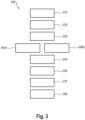
- FIG. 3 which illustrates in a diagram 200 a number of different modes 210 to 280, the operation of the munition controller 100 will now be described in another embodiment.
- the number here is merely exemplary, as the functions can also be combined into fewer modes or split into further ones.
- the different modes 210 to 280 may correspond to states of a state machine implemented in or by the munition controller 100.
- Mode 210 may correspond to the above-described first mode, mode 220 to an initialization mode, mode 230 to a standby mode, mode 240A to a manual arming mode, mode 240B to a remote arming mode, mode 250 to an arming execution mode, mode 260 to a lurking and/or loitering mode, mode 270 to a preparation mode, and mode 280 to the second mode.
- Each mode 210 to 280 may be or may correspond to a state of the state machine. A transition between the individual modes may therefore also refer to a change from one state to another, in a corresponding forward or backward direction.
- a respective transition between the modes may be triggered by at least one of operator input, e.g. remotely or manually, sensor input, e.g. from an onboard sensor or external and/or connected sensor, and internal logics, e.g. switches, position sensors for the fuzing mechanism, e.g. for detonator and/or the booster charge, or the like.
- operator input e.g. remotely or manually
- sensor input e.g. from an onboard sensor or external and/or connected sensor
- internal logics e.g. switches, position sensors for the fuzing mechanism, e.g. for detonator and/or the booster charge, or the like.
- the mode 210 i.e. the first mode
- the mode 210 may also be referred to as storage mode, in in which the munition controller 100 is in a safe status, i.e. the detonator 124 and the booster charge 122 are separated from each other, wherein the electric power supply 110 is disconnected for long-time storage, transportation and safe handling.
- the mode 280 i.e. the second mode, may also be referred to as engagement mode, in which the munition controller 100 is in partly armed or armed mode, operational and the sensor signal indicates a target.
- a detonator capacitor or the like may be charged. Transitioning from the first mode towards the at least one intermediate mode, e.g. forward transition, comprises connecting of the electrical power supply 110 and receiving manual operator input on-site.
- the manual input for transitioning from the first mode towards the at least one intermediate mode comprises at least one of a removal of a securing element, e.g. a securing pin or the like, from the munition controller, a button actuation, and a lever actuation.
- a securing element e.g. a securing pin or the like
- the first mode is an end mode or end state, there is no backward transition.
- forward transition may comprise activating the fuzing mechanism, e.g. closing a fuzing circuit, and initiating the detonator 124, thereby detonating the munition 12 via the booster charge 122.
- the second mode e.g.
- backward transition may comprise at least one of receiving a de-arming command from remote, receiving a manual de-arming procedure, e.g. by NFC controller, key code, or the like, and automatic de-arming due to lack of electric power, e.g. by low or depleted battery power.
- Automatic de-arming may comprise automatic reset to first mode, e.g. storage mode, wherein the electric power supply connection may be maintained and can be disconnected afterwards for the fully first mode, e.g. storage mode.
- the munition controller 100 may be in a safe status, i.e. the detonator 124 and the booster charge 122 are separated from each other, with connected power supply 110 and initializes itself.
- the initialization procedure may comprise at least one of a built-in test or self-check, a check for remote data links and/or connections, battery levels, or the like, to provide operational readiness. Results of the tests and/or checks may be displayed at the munition controller, e.g. by a display, LEDs, or remotely.
- forward transition may be performed if the initialization procedure is successful.
- Backward transition to the first mode e.g.
- storage mode may comprise at least one of an operator input, e.g. power off, or lack of electric power, e.g. low or depleted battery, wherein the electric power supply connection may be maintained and can be disconnected afterwards for the fully first mode, e.g. storage mode.
- an operator input e.g. power off
- lack of electric power e.g. low or depleted battery
- the munition controller 100 may be in a safe status, i.e. the detonator 124 and the booster charge 122 are separated from each other, with connected power supply 110 and successfully initialized.
- the munition controller 100 may be configured to wait for further commands in form of e.g. a manual arming command, a remote network link for remote arming, or the like.
- forward transition to the arming mode may comprise receiving a respective arming command for manual or remote arming, wherein the arming command may comprise an operator input, establishing a network link and/or connection, an arming command verification, or the like.
- Backward transition to the first mode e.g.
- storage mode may comprise at least one of an operator input, e.g. power off, a lack of power, e.g. low or depleted battery, an automatic rule-based transition, e.g. automatic transition or shutdown to the first mode, e.g. storage, mode after a predefined time elapsed, e.g. 60 minutes without network connection, 200 days with network connection), wherein the electric power supply connection may be maintained and can be disconnected afterwards for the fully first mode, e.g. storage mode.
- an operator input e.g. power off
- a lack of power e.g. low or depleted battery
- an automatic rule-based transition e.g. automatic transition or shutdown to the first mode, e.g. storage, mode after a predefined time elapsed, e.g. 60 minutes without network connection, 200 days with network connection
- the electric power supply connection may be maintained and can be disconnected afterwards for the fully first mode, e.g. storage mode.
- the munition controller 100 may be in a safe status, i.e. the detonator 124 and the booster charge 122 are separated from each other, with connected power supply 110 and operational.
- An operator may select manual arming by input, e.g. by a push button, lever, or the like, by a pre-defined hardware setup, e.g. by an internal switch to deactivate the remote link or capability.
- mode 240B i.e. the remote arming mode
- the munition controller 100 may be in a safe status, i.e. the detonator 1224 and the booster charge 122 are separated from each other, with connected power supply 110 and operational.
- the operator may select remote arming by e.g. activating, linking and/or pairing the munition controller with a remote controller or the like.
- the munition controller will neither automatically, nor by manual input jump back to standby mode. This ensures that the munition controller can be controlled exclusively by the remote controller and tampering or hijacking of the munition is not possible by jamming or manual recovery.
- forward transition may comprise meeting at least one manual arming criterion comprising at least one of a manual operator input indicating a manual arming command, a hardware configuration of the munition controller, and a ruled-based manual arming criterion.
- Backward transition to the first mode e.g.
- forward transition to the arming execution mode may comprise meeting a remote arming criterion is met comprising at least one of receiving a remote arming command and completing verification and a rule-based arming criterion, e.g. low-acceleration for a predefined time, or the like.
- Backward transition to the first mode e.g.
- storage mode may comprise at least one Backward transition to the first mode, e.g. storage mode, may comprise automatic rule-based transition, e.g. if remote arming exceeds operational endurance limitation (e. g. 120 days), or at a lack of electric power, e.g. low or depleted battery, wherein the electric power supply connection may be maintained and can be disconnected afterwards for the fully first mode, e.g. storage mode.
- operational endurance limitation e. g. 120 days
- electric power supply connection e.g. low or depleted battery
- the munition controller 100 may be in a safe status, i.e. the detonator 124 and the booster charge 122 are separated from each other, with connected power supply 110 and operational, wherein the manual arming or remote arming procedure was completed successfully.
- forward transition may comprise charging at least one capacitor to store the required power to de-arm in case of lack of power and/or for transitioning to partly armed status or fully armed status.
- Backward transition to the manual or remote arming mode i.e. mode 240A or mode 240B, may be performed if the desired status cannot be achieved, e.g. due to component failure or the like.
- Backward transition or reset to the first mode may be performed at lack of electric energy, e.g. low or depleted battery, wherein the electric power supply connection may be maintained and can be disconnected afterwards for the fully first mode, e.g. storage mode.
- the munition controller 100 may be in a partly armed or armed status and operational. In this mode, the at least one sensor 140 may be activated to detect nearby targets.
- forward transition may be performed if a target is in range.
- Backward transition to the remote arming mode i.e. mode 240B, may comprise receiving a remote de-arming command.
- Backward transition to the manual arming mode i.e. mode 240A, may comprise receiving a manual de-arming procedure, e.g.
- NFC controller key code, or the like
- automatic de-arming due to lack of electric power e.g. by low or depleted battery power.
- Backward transition or automatic de-arming to and/or reset to the first mode, e.g. storage mode, i.e. mode 210, may be performed at lack of electric energy, wherein the electric power supply connection may be maintained and can be disconnected afterwards for the fully first mode, e.g. storage mode.
- the munition controller 100 may be in a partly armed or armed status, operational, and the at least one sensor 140 detected a nearby target.
- forward transition to the second mode i.e. mode 280, may comprise at least one of enabling fully armed status, if required, and charging a fuzing capacitor.
- Backward transition to the lurking and/or loitering mode i.e. mode 260, may be performed a predefined time elapsed, e.g. 120 s.
- Backward transition to the remote arming mode, i.e. mode 240B may comprise receiving a remote de-arming command.
- Backward transition to the manual arming mode may comprise receiving a manual de-arming procedure, e.g. by NFC controller, key code, or the like, and automatic de-arming due to lack of electric power, e.g. by low or depleted battery power.
- Backward transition or automatic de-arming to and/or reset to the first mode e.g. storage mode, i.e. mode 210, may be performed at lack of electric energy, wherein the electric power supply connection may be maintained and can be disconnected afterwards for the fully first mode, e.g. storage mode, i.e. mode 210.
- Fig. 4 illustrates in a flow chart a method 300 for selectively de-arming, arming and/or fuzing of remotely controllable munition.
- the method comprises, 310, in a first mode, disabling a fuzing mechanism of the munition controller by separating a booster charge and a detonator from each other, wherein an electrical power supply of the munition controller is disconnected.
- the method further comprises, 320, in at least one intermediate mode, establishing operational readiness of the munition controller with the electrical power supply being connected and at least partly arming the fuzing mechanism.
- the method comprises, 330, in a second mode, enabling triggering of the at least partly armed fuzing mechanism based on a sensor signal indicative for a detected target.
- the transitioning from the first mode towards the at least one intermediate mode comprises connecting of the electrical power supply and receiving manual operator input on-site.
Landscapes
- Engineering & Computer Science (AREA)
- General Engineering & Computer Science (AREA)
- Charge And Discharge Circuits For Batteries Or The Like (AREA)
Abstract
Description
- The present invention relates to a method for selectively de-arming, arming and/or fuzing of remotely controllable munition, and a corresponding munition controller.
- A munition system, in particular a remotely controllable munition system, may comprise munition and an on-board munition controller including a fuzing mechanism for detonating the munition, in which a triggerable detonator is configured to ignite a booster charge that in turn is configured to detonate the munition. Such a munition system may be, for example, a guided weapon, a self-guided missile, a missile, a bomb, a grenade, a mine, or the like.
- Such a munition system is subject to certain safety requirements during its entire product life cycle. This applies, for example, to the storage, handling and/or use of such a munition system. It should be ensured that the munition system is in a safe state or mode or that a safe state or mode can be achieved if necessary.
- It is therefore an object of the present invention to enable safe handling of munition with simple measures.
- This object is solved by the subject-matter of the appended independent claims. Further embodiments are defined in the appended dependent claims and the following description.
- According to a first aspect, there is provided a method for selectively de-arming, arming and/or fuzing of remotely controllable and/or detonatable munition. The method is applied to a munition controller coupleable or coupled to the munition and operable in multiple modes. The method comprises in a first mode, disabling a fuzing mechanism of the munition controller by separating a booster charge and a detonator from each other, wherein an electrical power supply of the munition controller is disconnected. The method further comprises in at least one intermediate mode, establishing operational readiness of the munition controller with the electrical power supply being connected and at least partly arming the fuzing mechanism. In addition, the method comprises in a second mode, enabling triggering of the at least partly armed fuzing mechanism based on a sensor signal indicative for a detected target. Thereby, transitioning from the first mode towards the at least one intermediate mode comprises connecting of the electrical power supply and receiving manual operator input on-site.
- The proposed method, and likewise the corresponding munition controller, allows for reducing and/or minimizing energy consumption within active munition lifetime. It enables remote and/or manual arming, de-arming, and re-arming of the munition controller and/or the munition to which the munition controller may be applied. The method and/or the munition controller may thus meet the requirements of the NATO standard STANAG 4187 (Edition A, Version 1, June 2022), for example. In the first mode, the method and/or the munition controller allows for long-time storage, transportation, and safe handling of the munition, as the munition controller and/or the munition is in a safe status and electrical power is disconnected. In the at least one intermediate mode, the method and/or the munition controller allows for e.g. initializing, standby, and at least partly arming of the munition controller and/or its fuzing mechanism. In the second mode, the method and/or the munition controller allows for detonating the munition, wherein de-arming, or a reset to the first mode is possible.
- As used herein, the munition controller may be any type of controller at least comprising the fuzing mechanism with a booster charge and a detonator. The munition controller may comprise or may be coupled to at least one actuator configured to displace, move, or the like the booster charge and the detonator relative to each other. In the first mode, the munition controller may be configured to displace, move, or the like the booster charge and the detonator relative to each other by controlling the at least one actuator accordingly. The munition controller may comprise or may be coupled to the electrical power supply. For example, the munition controller may include or be formed as: circuit, logic circuit, microprocessor, microcontroller, programmable controller, field programmable gate array (FPGA), application specific integrated circuits (ASIC), programmable logic controller (PLC), or the like.
- The electrical power supply may comprise at least one energy storage. The at least one energy storage may be configured to provide electrical energy for displacing, moving, or the like at least one of the booster charge and the detonator in case of failure, interruption, drop, etc. of the energy supply. In other words, the electrical energy supply may be configured, by providing an energy reserve, to always separate the booster charge and the detonator from each other, even in case of a failure, interruption, drop, etc. of the energy supply. This may comprise, for example, by charging one or more capacitors.
- The method may be understood as a kind of or a state machine or may be implemented as a logic circuit, state machine, or the like. Each mode described herein may be or may correspond to a state of the state machine. A transition between the individual modes as described herein may therefore also refer to a change from one state to another, in a corresponding forward or backward direction. A respective transition between the modes may be triggered by at least one of operator input, e.g. remotely or manually, sensor input, e.g. from an onboard sensor or external and/or connected sensor, and internal logics, e.g. switches, position sensors for the fuzing mechanism, e.g. for detonator and/or the booster charge, or the like. The number of different modes is not fixed herein but is variable. The two end modes or end states, i.e. the first mode and the second mode, may be fixed. Multiple intermediate modes or intermediate states arranged between the first mode and the second mode may be provided. As part of the at least one intermediate mode, an arming procedure should be completed before or by the second mode.
- Further, as used herein, the first mode may also be referred to as storage mode, in in which the munition controller is in a safe status, i.e. the detonator and the booster charge are separated from each other, wherein the electric power supply is disconnected for long-time storage, transportation and safe handling. The second mode may also be referred to as engagement mode, in which the munition controller, e.g. the fuzing mechanism, is in partly armed or armed mode, operational and the sensor signal indicates a target. A detonator capacitor or the like may be charged. As mentioned above, transitioning from the first mode towards the at least one intermediate mode, e.g. forward transition, comprises connecting of the electrical power supply and receiving manual operator input on-site. For example, the manual input for transitioning from the first mode towards the at least one intermediate mode comprises at least one of a removal of a securing element, e.g. a securing pin or the like, from the munition controller, a button actuation, and a lever actuation. As the first mode is an end mode or end state, there is no backward transition. From the second mode, e.g. engagement mode, forward transition may comprise activating the fuzing mechanism, e.g. closing a fuzing circuit, and initiating the detonator, thereby detonating the munition, via the booster charge. Further, from the second mode, e.g. engagement mode, backward transition may comprise at least one of receiving a de-arming command from remote, receiving a manual de-arming procedure, e.g. by NFC controller, key code, or the like, and automatic de-arming due to lack of electric power, e.g. by low or depleted battery power. Automatic de-arming may comprise automatic reset to first mode, e.g. storage mode, wherein the electric power supply connection may be maintained and can be disconnected afterwards for the fully first mode, e.g. storage mode.
- Further, for example, the at least one intermediate mode may comprise at least one of an initialization mode, a standby mode, a manual arming mode, a remote arming mode, an arming execution mode, a lurking and/or loitering mode, and a preparation mode.
- By way of example, in the initialization mode, munition controller may be in a safe status, i.e. the detonator and the booster charge are separated from each other, with connected power supply and initializes itself. The initialization procedure may comprise at least one of a built-in test or self-check, a check for remote data links and/or connections, battery levels, or the like, to provide operational readiness. Results of the tests and/or checks may be displayed at the munition controller, e.g. by a display, LEDs, or remotely. In the initialization mode, forward transition may be performed if the initialization procedure is successful. Backward transition to the first mode, e.g. storage mode, may comprise at least one of an operator input, e.g. power off, or lack of electric power, e.g. low or depleted battery, wherein the electric power supply connection may be maintained and can be disconnected afterwards for the fully first mode, e.g. storage mode.
- Further, by way of example, in the standby mode, the munition controller may be in a safe status, i.e. the detonator and the booster charge are separated from each other, with connected power supply and properly initialized. The munition controller may be configured to wait for further commands in form of e.g. a manual arming command, a remote network link for remote arming, or the like. In the standby mode, forward transition to the arming mode may comprise receiving a respective arming command for manual or remote arming, wherein the arming command may comprise an operator input, establishing a network link and/or connection, an arming command verification, or the like. Backward transition to the first mode, e.g. storage mode, may comprise at least one of an operator input, e.g. power off, a lack of power, e.g. low or depleted battery, an automatic rule-based transition, e.g. automatic transition or shutdown to the first mode, e.g. storage, mode after a predefined time elapsed, e.g. 60 minutes without network connection, 200 days with network connection), wherein the electric power supply connection may be maintained and can be disconnected afterwards for the fully first mode, e.g. storage mode.
- By way of example, in the manual arming mode, the munition controller may be in a safe status, i.e. the detonator and the booster charge are separated from each other, with connected power supply and operational. An operator may select manual arming by input, e.g. by a push button, lever, or the like, by a pre-defined hardware setup, e.g. by an internal switch to deactivate the remote link or capability. In the remote arming mode, the munition controller may be in a safe status, i.e. the detonator and the booster charge are separated from each other, with connected power supply and operational. The operator may select remote arming by e.g. activating, linking and/or pairing the munition controller with a remote controller or the like. In contrast to the manual arming mode, the munition controller will neither automatically, nor by manual input jump back to standby mode. This ensures that the munition controller can be controlled exclusively by the remote controller and tampering or hijacking of the munition is not possible by jamming or manual recovery. In the manual arming mode, forward transition may comprise meeting at least one manual arming criterion comprising at least one of a manual operator input indicating a manual arming command, a hardware configuration of the munition controller, and a ruled-based manual arming criterion. Backward transition to the first mode, e.g. storage mode, may comprise automatic rule-based transition, e.g. if manual arming procedure is not competed successfully, e.g. with a predefined time, e.g. 60 min or at a lack of electric power, e.g. low or depleted battery, wherein the electric power supply connection may be maintained and can be disconnected afterwards for the fully first mode, e.g. storage mode. In the remote arming mode, forward transition to the arming execution mode, may comprise meeting a remote arming criterion is met comprising at least one of receiving a remote arming command and completing verification and a rule-based arming criterion, e.g. low-acceleration for a predefined time, or the like. Backward transition to the first mode, e.g. storage mode may comprise at least one Backward transition to the first mode, e.g. storage mode, may comprise automatic rule-based transition, e.g. if remote arming exceeds operational endurance limitation (e. g. 120 days), or at a lack of electric power, e.g. low or depleted battery, wherein the electric power supply connection may be maintained and can be disconnected afterwards for the fully first mode, e.g. storage mode.
- Further, by way of example, in the arming execution mode, the munition controller may be in a safe status, i.e. the detonator and the booster charge are separated from each other, with connected power supply and operational, wherein the manual arming or remote arming procedure was completed successfully. In the arming execution mode, forward transition may comprise charging capacitors to store the required power to de-arm in case of lack of power and/or for transitioning to partly-armed status or fully armed status. Backward transition to the manual or remote arming mode may be performed if the desired status cannot be achieved, e.g. due to component failure or the like. Backward transition or reset to the first mode, e.g. storage mode, may be performed at lack of electric energy, e.g. low or depleted battery, wherein the electric power supply connection may be maintained and can be disconnected afterwards for the fully first mode, e.g. storage mode.
- By way of example, in the lurking and/or loitering mode, the munition controller may be in a partly armed or armed status and operational. In this mode, at least one sensor of the munition controller may be activated to detect nearby targets. In the lurking and/or loitering mode, forward transition may be performed if a target is in range. Backward transition to the remote arming mode may comprise receiving a remote de-arming command. Backward transition to the manual arming mode may comprise receiving a manual de-arming procedure, e.g. by NFC controller, key code, or the like, and automatic de-arming due to lack of electric power, e.g. by low or depleted battery power. Backward transition or automatic de-arming to and/or reset to the first mode, e.g. storage mode, may be performed at lack of electric energy, wherein the electric power supply connection may be maintained and can be disconnected afterwards for the fully first mode, e.g. storage mode.
- Further, by way of example, in the preparation mode, the munition controller may be in a partly armed or armed status, operational, and the at least one sensor detected a nearby target. In the preparation mode, forward transition to the second mode may comprise at least one of enabling fully armed status, if required, and charging a fuzing capacitor. Backward transition to the lurking and/or loitering mode may be performed a predefined time elapsed, e.g. 120 s. Backward transition to the remote arming mode may comprise receiving a remote de-arming command. Backward transition to the manual arming mode may comprise receiving a manual de-arming procedure, e.g. by NFC controller, key code, or the like, and automatic de-arming due to lack of electric power, e.g. by low or depleted battery power. Backward transition or automatic de-arming to and/or reset to the first mode, e.g. storage mode, may be performed at lack of electric energy, wherein the electric power supply connection may be maintained and can be disconnected afterwards for the fully first mode, e.g. storage mode.
- According to an embodiment, the first mode, the at least one intermediate mode and the second mode may be in sequential order and/or arranged sequentially. For example, the method and/or the modes may be implemented by a state machine having sequenced states. The first mode, e.g. storage mode, may be reachable from all modes. Sequential implementation can be easily implemented in simple logic, electronics, or the like. In addition, the transitions between the states allow safe operation.
- In an embodiment, in case of lack of electrical power of the munition controller automatic transition to the first mode is performed. That is, the munition controller can always be set to a safe state.
- According to an embodiment, the at least partly arming of the fuzing mechanism comprises at least one of bringing the booster charge and the detonator together and removing an interrupter arranged between the booster charge and the detonator. For example, the booster charge and the detonator may be movable relative to each other by at least one actuator controllable by the munition controller. In the partly armed status, at least one of the booster charge and the detonator may be in a safe state, e.g. a safe position, while the other is already in an operational state, e.g. operational position. In the fully armed state, both the booster charge and the detonator may be in an operational state, e.g. operational position.
- In an embodiment, establishing operational readiness comprises performing at least one self-check of the munition controller, wherein proceeding with the at least partly arming depends on the at least one self-check being successful. For example, the at least one self-check may comprise checking operability of actuators, checking battery level, checking for remote link and/or connection, or the like. The result of the at least on self-check may be displayed, e.g. by a display, LEDs, or the like.
- According to an embodiment, the at least partly arming may selected from manual arming and remote arming, based on whether at least one manual arming criterion or at least one remote arming criterion is met.
- In an embodiment, the at least one manual arming criterion may comprise at least one of a manual operator input indicating a manual arming command, a hardware configuration of the munition controller, and a ruled-based manual arming criterion. For example, the manual operator input may comprise a button actuation or the like. The hardware configuration may comprise an internal switch to deactivate the remote link and/or remote capability.
- According to an embodiment, the at least one remote arming criterion may comprise at least one of receiving a remote arming command signal, a hardware configuration of the munition controller, and availability of a remote communication link.
- In an embodiment, if manual arming is selected, transitioning from the at least partly arming towards operational readiness and/or the first mode is triggered by at least one of receiving an operator input, a lack of electrical power, and a rule-based automatic transition.
- According to an embodiment, if remote arming is selected, transitioning from the at least partly arming towards operational readiness is prevented.
- In an embodiment, if remote arming is selected, transitioning from the at least partly arming towards the first mode is triggered by at least one of a lack of electrical power and a rule-based automatic transition.
- According to an embodiment, transitioning from the at least partly arming towards the second mode comprises charging at least one energy storage of the electrical power supply for providing power for de-arming.
- In an embodiment, transitioning from the second mode towards the at least one intermediate mode and/or the first mode comprises at least one of receiving of an operator input, receiving a de-arming command, and a rule-based automatic transition.
- According to a further aspect, there is provided a munition controller for selectively de-arming, arming and/or detonating of remotely controllable munition. The munition controller comprises an electrical power supply. The munition controller further comprises a fuzing mechanism coupled to the electrical power supply. The munition controller is configured to enable carrying out the method described herein.
- According to another aspect, there is provided a munition system. The munition system comprises a remotely detonable munition and a munition controller described herein.
- The present invention is explained in more detail below with reference to the embodiments shown in the schematic figures:
- Fig. 1
- schematically illustrates an exemplary munition system comprising a munition and a munition controller for selectively de-arming, arming and/or detonating of remotely controllable munition according to an embodiment.
- Fig. 2
- schematically illustrates an exemplary munition system comprising a munition and a munition controller for selectively de-arming, arming and/or detonating of remotely controllable munition according to an embodiment.
- Fig. 3
- illustrates in a diagram a state machine of a munition controller according to an embodiment.
- Fig. 4
- illustrates in a flow chart a method for selectively de-arming, arming and/or detonating of remotely controllable munition according to an embodiment.
- In the figures of the drawing, elements, features, and components which are identical, functionally identical and of identical action are denoted in each case by the same reference designations unless stated otherwise.
-
Fig. 1 schematically illustrates in a top view anexemplary munition controller 100 for selectively de-arming, arming and/or detonating of remotelycontrollable munition 12. Themunition controller 100 may be coupled to, e.g., attached to, the munition to detonate the munition when needed. The munition controller100 may be operated in several different states or modes of operation. Themunition 12 may be, for example, a guided weapon, a self-guided missile, a rocket, a bomb, a grenade, a mine, a "lurking weapon" (Loitering Weapon), or the like. Themunition controller 100 and the munition may form a munition system. - The
munition controller 100 comprises anelectrical power supply 110. Themunition controller 100 further comprises afuzing mechanism 120 coupled to theelectrical power supply 110. Thefuzing mechanism 120 comprises abooster charge 122 and adetonator 124. Thedetonator 124 may be configured to ignite the booster charge 112 that in turn may be configured to detonate themunition 12. Optionally, thefuzing mechanism 120 may comprise an interrupter or like that can be selectively arranged between the booster charge and the detonator. For example, for control functions, themunition controller 100 may comprisecontrol circuitry 130 including at least one of: a circuit, a logic circuit, a microprocessor, a microcontroller, a programmable controller, a field programmable gate array (FPGA), an application specific integrated circuits (ASIC), a programmable logic controller (PLC), or the like, coupled to theelectrical power supply 110 and thefuzing mechanism 120. Further, themunition controller 100 may comprise or may be coupled to at least onesensor element 140 configured to detect targets in the vicinity of themunition controller 100 and/or themunition 12. - The
munition controller 100 is coupleable to themunition 12 and operable in multiple modes. The modes may be implemented by a logic circuit, state machine or the like. Operation of theammunition controller 12 may be as described below. - In a first mode, the
fuzing mechanism 120 of themunition controller 100 may be disabled by separating thebooster charge 122 and the detonator from each other, wherein theelectrical power supply 110 of themunition controller 100 is disconnected. Theelectrical power supply 110 may be disconnected by manual operation, e.g. by removing at least part of theelectrical power supply 110, by a power switch, or the like, or automatically by power shutdown. - In at least one intermediate mode, operational readiness of the
munition controller 100 may be established with theelectrical power supply 110 being connected and at least partly arming thefuzing mechanism 120. The transitioning from the first mode towards the at least one intermediate mode may comprise connecting of theelectrical power supply 110 and receiving manual operator input on-site. For example, the manual input for transitioning from the first mode towards the at least one intermediate mode comprises at least one of a removal of a securing element, e.g. a securing pin or the like, from the munition controller, a button actuation, and a lever actuation. - In a second mode, enabling triggering of the at least partly
armed fuzing mechanism 120 based on a sensor signal indicative for a detected target. The sensor signal may be provided by the at least onesensor 140 and/or by other sensors, such as remote sensors, wherein themunition controller 100 may be configured to receive signals and/or data from remote. - For example, the first mode, the at least one intermediate mode and the second mode are in sequential order. In at least some embodiments, in case of lack of electrical power of the
munition controller 100, automatic transition to the first mode may be performed. -
Fig. 2 schematically illustrates themunition system 10 comprising themunition 12 and themunition controller 100 in another view. It should be noted that themunition system 10 illustrated is merely exemplary and may be designed otherwise. - With reference to
Fig. 3 , which illustrates in a diagram 200 a number ofdifferent modes 210 to 280, the operation of themunition controller 100 will now be described in another embodiment. The number here is merely exemplary, as the functions can also be combined into fewer modes or split into further ones. - The
different modes 210 to 280 may correspond to states of a state machine implemented in or by themunition controller 100.Mode 210 may correspond to the above-described first mode,mode 220 to an initialization mode,mode 230 to a standby mode,mode 240A to a manual arming mode,mode 240B to a remote arming mode,mode 250 to an arming execution mode,mode 260 to a lurking and/or loitering mode,mode 270 to a preparation mode, andmode 280 to the second mode. Eachmode 210 to 280 may be or may correspond to a state of the state machine. A transition between the individual modes may therefore also refer to a change from one state to another, in a corresponding forward or backward direction. A respective transition between the modes may be triggered by at least one of operator input, e.g. remotely or manually, sensor input, e.g. from an onboard sensor or external and/or connected sensor, and internal logics, e.g. switches, position sensors for the fuzing mechanism, e.g. for detonator and/or the booster charge, or the like. - The
mode 210, i.e. the first mode, may also be referred to as storage mode, in in which themunition controller 100 is in a safe status, i.e. thedetonator 124 and thebooster charge 122 are separated from each other, wherein theelectric power supply 110 is disconnected for long-time storage, transportation and safe handling. Themode 280, i.e. the second mode, may also be referred to as engagement mode, in which themunition controller 100 is in partly armed or armed mode, operational and the sensor signal indicates a target. A detonator capacitor or the like may be charged. Transitioning from the first mode towards the at least one intermediate mode, e.g. forward transition, comprises connecting of theelectrical power supply 110 and receiving manual operator input on-site. For example, the manual input for transitioning from the first mode towards the at least one intermediate mode comprises at least one of a removal of a securing element, e.g. a securing pin or the like, from the munition controller, a button actuation, and a lever actuation. As the first mode is an end mode or end state, there is no backward transition. From the second mode, e.g. engagement mode, forward transition may comprise activating the fuzing mechanism, e.g. closing a fuzing circuit, and initiating thedetonator 124, thereby detonating themunition 12 via thebooster charge 122. Further, from the second mode, e.g. engagement mode, backward transition may comprise at least one of receiving a de-arming command from remote, receiving a manual de-arming procedure, e.g. by NFC controller, key code, or the like, and automatic de-arming due to lack of electric power, e.g. by low or depleted battery power. Automatic de-arming may comprise automatic reset to first mode, e.g. storage mode, wherein the electric power supply connection may be maintained and can be disconnected afterwards for the fully first mode, e.g. storage mode. - In
mode 220, i.e. the initialization mode, themunition controller 100 may be in a safe status, i.e. thedetonator 124 and thebooster charge 122 are separated from each other, withconnected power supply 110 and initializes itself. The initialization procedure may comprise at least one of a built-in test or self-check, a check for remote data links and/or connections, battery levels, or the like, to provide operational readiness. Results of the tests and/or checks may be displayed at the munition controller, e.g. by a display, LEDs, or remotely. Inmode 220, i.e. the initialization mode, forward transition may be performed if the initialization procedure is successful. Backward transition to the first mode, e.g. storage mode, may comprise at least one of an operator input, e.g. power off, or lack of electric power, e.g. low or depleted battery, wherein the electric power supply connection may be maintained and can be disconnected afterwards for the fully first mode, e.g. storage mode. - In
mode 230, i.e. in the standby mode, themunition controller 100 may be in a safe status, i.e. thedetonator 124 and thebooster charge 122 are separated from each other, withconnected power supply 110 and successfully initialized. Themunition controller 100 may be configured to wait for further commands in form of e.g. a manual arming command, a remote network link for remote arming, or the like. In the standby mode, forward transition to the arming mode may comprise receiving a respective arming command for manual or remote arming, wherein the arming command may comprise an operator input, establishing a network link and/or connection, an arming command verification, or the like. Backward transition to the first mode, e.g. storage mode, may comprise at least one of an operator input, e.g. power off, a lack of power, e.g. low or depleted battery, an automatic rule-based transition, e.g. automatic transition or shutdown to the first mode, e.g. storage, mode after a predefined time elapsed, e.g. 60 minutes without network connection, 200 days with network connection), wherein the electric power supply connection may be maintained and can be disconnected afterwards for the fully first mode, e.g. storage mode. - In
mode 240A, i.e. in the manual arming mode, themunition controller 100 may be in a safe status, i.e. thedetonator 124 and thebooster charge 122 are separated from each other, withconnected power supply 110 and operational. An operator may select manual arming by input, e.g. by a push button, lever, or the like, by a pre-defined hardware setup, e.g. by an internal switch to deactivate the remote link or capability. Inmode 240B, i.e. the remote arming mode, themunition controller 100 may be in a safe status, i.e. the detonator 1224 and thebooster charge 122 are separated from each other, withconnected power supply 110 and operational. The operator may select remote arming by e.g. activating, linking and/or pairing the munition controller with a remote controller or the like. In contrast to the manual arming mode, the munition controller will neither automatically, nor by manual input jump back to standby mode. This ensures that the munition controller can be controlled exclusively by the remote controller and tampering or hijacking of the munition is not possible by jamming or manual recovery. In the manual arming mode, forward transition may comprise meeting at least one manual arming criterion comprising at least one of a manual operator input indicating a manual arming command, a hardware configuration of the munition controller, and a ruled-based manual arming criterion. Backward transition to the first mode, e.g. storage mode, may comprise automatic rule-based transition, e.g. if manual arming procedure is not competed successfully, e.g. with a predefined time, e.g. 60 min or at a lack of electric power, e.g. low or depleted battery, wherein the electric power supply connection may be maintained and can be disconnected afterwards for the fully first mode, e.g. storage mode. In the remote arming mode, forward transition to the arming execution mode, may comprise meeting a remote arming criterion is met comprising at least one of receiving a remote arming command and completing verification and a rule-based arming criterion, e.g. low-acceleration for a predefined time, or the like. Backward transition to the first mode, e.g. storage mode may comprise at least one Backward transition to the first mode, e.g. storage mode, may comprise automatic rule-based transition, e.g. if remote arming exceeds operational endurance limitation (e. g. 120 days), or at a lack of electric power, e.g. low or depleted battery, wherein the electric power supply connection may be maintained and can be disconnected afterwards for the fully first mode, e.g. storage mode. - In
mode 250, i.e. in the arming execution mode, themunition controller 100 may be in a safe status, i.e. thedetonator 124 and thebooster charge 122 are separated from each other, withconnected power supply 110 and operational, wherein the manual arming or remote arming procedure was completed successfully. Inmode 250, i.e. the arming execution mode, forward transition may comprise charging at least one capacitor to store the required power to de-arm in case of lack of power and/or for transitioning to partly armed status or fully armed status. Backward transition to the manual or remote arming mode, i.e.mode 240A ormode 240B, may be performed if the desired status cannot be achieved, e.g. due to component failure or the like. Backward transition or reset to the first mode, e.g. storage mode, i.e.mode 210, may be performed at lack of electric energy, e.g. low or depleted battery, wherein the electric power supply connection may be maintained and can be disconnected afterwards for the fully first mode, e.g. storage mode. - In
mode 260, i.e. in the lurking and/or loitering mode, themunition controller 100 may be in a partly armed or armed status and operational. In this mode, the at least onesensor 140 may be activated to detect nearby targets. Inmode 260, i.e. the lurking and/or loitering mode, forward transition may be performed if a target is in range. Backward transition to the remote arming mode, i.e.mode 240B, may comprise receiving a remote de-arming command. Backward transition to the manual arming mode, i.e.mode 240A, may comprise receiving a manual de-arming procedure, e.g. by NFC controller, key code, or the like, and automatic de-arming due to lack of electric power, e.g. by low or depleted battery power. Backward transition or automatic de-arming to and/or reset to the first mode, e.g. storage mode, i.e.mode 210, may be performed at lack of electric energy, wherein the electric power supply connection may be maintained and can be disconnected afterwards for the fully first mode, e.g. storage mode. - In
mode 270, i.e. in the preparation mode, themunition controller 100 may be in a partly armed or armed status, operational, and the at least onesensor 140 detected a nearby target. Inmode 270, i.e. the preparation mode, forward transition to the second mode, i.e.mode 280, may comprise at least one of enabling fully armed status, if required, and charging a fuzing capacitor. Backward transition to the lurking and/or loitering mode, i.e.mode 260, may be performed a predefined time elapsed, e.g. 120 s. Backward transition to the remote arming mode, i.e.mode 240B, may comprise receiving a remote de-arming command. Backward transition to the manual arming mode, i.e.mode 240A, may comprise receiving a manual de-arming procedure, e.g. by NFC controller, key code, or the like, and automatic de-arming due to lack of electric power, e.g. by low or depleted battery power. Backward transition or automatic de-arming to and/or reset to the first mode, e.g. storage mode, i.e.mode 210, may be performed at lack of electric energy, wherein the electric power supply connection may be maintained and can be disconnected afterwards for the fully first mode, e.g. storage mode, i.e.mode 210. -
Fig. 4 illustrates in a flow chart amethod 300 for selectively de-arming, arming and/or fuzing of remotely controllable munition. The method comprises, 310, in a first mode, disabling a fuzing mechanism of the munition controller by separating a booster charge and a detonator from each other, wherein an electrical power supply of the munition controller is disconnected. The method further comprises, 320, in at least one intermediate mode, establishing operational readiness of the munition controller with the electrical power supply being connected and at least partly arming the fuzing mechanism. In addition, the method comprises, 330, in a second mode, enabling triggering of the at least partly armed fuzing mechanism based on a sensor signal indicative for a detected target. The transitioning from the first mode towards the at least one intermediate mode comprises connecting of the electrical power supply and receiving manual operator input on-site. - In the foregoing detailed description, various features are grouped together in one or more examples or examples with the purpose of streamlining the disclosure. It is to be understood that the above description is intended to be illustrative, and not restrictive. It is intended to cover all alternatives, modifications and equivalents. Many other examples will be apparent to one skilled in the art upon reviewing the above specification. The embodiments were chosen and described in order to best explain the principles of the invention and its practical applications, to thereby enable others skilled in the art to best utilize the invention and various embodiments with various modifications as are suited to the particular use contemplated.
-
- 10
- munition system
- 12
- munition
- 100
- munition controller
- 110
- electrical power supply
- 120
- fuzing mechanism
- 122
- booster charge
- 124
- detonator
- 130
- control circuitry
- 140
- sensor
- 200
- diagram (e.g. state machine)
- 210-280
- modes and/or states
- 300
- method
- 310-330
- method step(s)
Claims (15)
- A method (300) for selectively de-arming, arming and/or fuzing of remotely controllable munition (12), the method being applied to a munition controller (100) coupleable or coupled to the munition and operable in multiple modes, and the method comprising:in a first mode (310), disabling a fuzing mechanism (120) of the munition controller (100) by separating a booster charge (122) and a detonator (124) from each other, wherein an electrical power supply (110) of the munition controller (100) is disconnected;in at least one intermediate mode (320), establishing operational readiness of the munition controller (100) with the electrical power supply (110) being connected and at least partly arming the fuzing mechanism (120); andin a second mode (330), enabling triggering of the at least partly armed fuzing mechanism based on a sensor signal indicative for a detected ta rg et;wherein transitioning from the first mode towards the at least one intermediate mode comprises connecting of the electrical power supply (110) and receiving manual operator input on-site.
- The method of claim 1, wherein the first mode, the at least one intermediate mode and the second mode are in sequential order.
- The method of claim 1 or 2, wherein in case of lack of electrical power of the munition controller (100) automatic transition to the first mode is performed.
- The method of any one of the preceding claims, wherein the at least partly arming of the fuzing mechanism (120) comprises at least one of bringing the booster charge (122) and the detonator (124) together and removing an interrupter arranged between the booster charge (122) and the detonator (124).
- The method of any one of the preceding claims, wherein establishing operational readiness comprises performing at least one self-check of the munition controller (100), wherein proceeding with the at least partly arming depends on the at least one self-check being successful.
- The method of any one of the preceding claims, wherein the at least partly arming is selected from manual arming and remote arming, based on whether at least one manual arming criterion or at least one remote arming criterion is met.
- The method of claim 6, wherein the at least one manual arming criterion comprises at least one of a manual operator input indicating a manual arming command, a hardware configuration of the munition controller, and a ruled-based manual arming criterion.
- The method of claim 6 or 7, wherein the at least one remote arming criterion comprises at least one of receiving a remote arming command signal, a hardware configuration of the munition controller, and availability of a remote communication link.
- The method of any one of claims 6 to 8, wherein, if manual arming is selected, transitioning from the at least partly arming towards operational readiness and/or the first mode is triggered by at least one of receiving an operator input, a lack of electrical power, and a rule-based automatic transition.
- The method of any one of claims 6 to 9, wherein, if remote arming is selected, transitioning from the at least partly arming towards operational readiness is prevented.
- The method of any one of claims 8 to 10, wherein, if remote arming is selected, transitioning from the at least partly arming towards the first mode is triggered by at least one of a lack of electrical power and a rule-based automatic transition.
- The method of any one of the preceding claims, wherein transitioning from the at least partly arming towards the second mode comprises charging at least one energy storage of the electrical power supply for providing power for de-arming.
- The method of any one of the preceding claims, wherein transitioning from the second mode towards the at least one intermediate mode and/or the first mode comprises at least one of receiving of an operator input, receiving a de-arming command, and a rule-based automatic transition.
- A munition controller for selectively de-arming, arming and/or detonating of remotely controllable munition, the munition controller comprising:an electrical power supply (110); anda fuzing mechanism (120) coupled to the electrical power supply (110);wherein the munition controller (100) is configured to enable carrying out the method according to any one of the preceding claims.
- A munition system (10), comprising a remotely detonable munition (12) and a munition controller (100) according to claim 14.
Priority Applications (1)
| Application Number | Priority Date | Filing Date | Title |
|---|---|---|---|
| EP23306928.5A EP4553445A1 (en) | 2023-11-09 | 2023-11-09 | Method for selectively de-arming, arming and/or fuzing of remotely controllable munition, and munition controller |
Applications Claiming Priority (1)
| Application Number | Priority Date | Filing Date | Title |
|---|---|---|---|
| EP23306928.5A EP4553445A1 (en) | 2023-11-09 | 2023-11-09 | Method for selectively de-arming, arming and/or fuzing of remotely controllable munition, and munition controller |
Publications (1)
| Publication Number | Publication Date |
|---|---|
| EP4553445A1 true EP4553445A1 (en) | 2025-05-14 |
Family
ID=90057480
Family Applications (1)
| Application Number | Title | Priority Date | Filing Date |
|---|---|---|---|
| EP23306928.5A Pending EP4553445A1 (en) | 2023-11-09 | 2023-11-09 | Method for selectively de-arming, arming and/or fuzing of remotely controllable munition, and munition controller |
Country Status (1)
| Country | Link |
|---|---|
| EP (1) | EP4553445A1 (en) |
Citations (2)
| Publication number | Priority date | Publication date | Assignee | Title |
|---|---|---|---|---|
| US3908553A (en) * | 1969-09-03 | 1975-09-30 | Us Navy | Anti-recovery device disarming mechanism |
| FR2679325A1 (en) * | 1991-07-15 | 1993-01-22 | Giat Ind Sa | Safety and arming unit with bistable flap |
-
2023
- 2023-11-09 EP EP23306928.5A patent/EP4553445A1/en active Pending
Patent Citations (2)
| Publication number | Priority date | Publication date | Assignee | Title |
|---|---|---|---|---|
| US3908553A (en) * | 1969-09-03 | 1975-09-30 | Us Navy | Anti-recovery device disarming mechanism |
| FR2679325A1 (en) * | 1991-07-15 | 1993-01-22 | Giat Ind Sa | Safety and arming unit with bistable flap |
Similar Documents
| Publication | Publication Date | Title |
|---|---|---|
| US7905177B2 (en) | Safe and arm system for a robot | |
| US3451306A (en) | Safe and arm ejection system | |
| US6300764B1 (en) | Apparatus and method for performing built-in testing of a squib fire network | |
| US9250051B1 (en) | Squib initiation sequencer | |
| US8887640B1 (en) | Electro-mechanical fuze for hand grenades | |
| US6295932B1 (en) | Electronic safe arm and fire device | |
| US4478127A (en) | Bomb saddle interface module | |
| US3703145A (en) | Selective arming mode and detonation option ordnance fuze | |
| US4911382A (en) | Safe electro ballistic escape sequencing system | |
| US8925462B2 (en) | Intermediate voltage arming | |
| US11047340B2 (en) | Integrated warhead ESAD/multi-pulse rocket motor EISD device | |
| US7334523B2 (en) | Fuze with electronic sterilization | |
| US7698849B2 (en) | Combined electrical mechanical firing systems | |
| RU2457430C1 (en) | Detonating fuse protection and commutation device | |
| CN115790290A (en) | Tactical missile initiating explosive device delay ignition circuit and control method | |
| US4960032A (en) | Apparatus for locking and unlocking a safety for subammunition bodies | |
| US6629498B1 (en) | Proximity submunition fuze safety logic | |
| US4833991A (en) | Submunition incorporating a fuze | |
| US4212246A (en) | Fuze electronic circuitry | |
| KR101885730B1 (en) | General purpose electronic safety and arming device with flight environment and target collision detection function | |
| NO321418B1 (en) | Electronic timed ignition for a projectile | |
| JP5121064B2 (en) | Detonation system | |
| US20120210896A1 (en) | Electrically Initiated Inertial Igniters for Thermal Batteries and the Like | |
| GB2575989A (en) | A safety and arming unit for a munition | |
| US9285198B2 (en) | Arm-fire devices and methods for pyrotechnic systems |
Legal Events
| Date | Code | Title | Description |
|---|---|---|---|
| PUAI | Public reference made under article 153(3) epc to a published international application that has entered the european phase |
Free format text: ORIGINAL CODE: 0009012 |
|
| STAA | Information on the status of an ep patent application or granted ep patent |
Free format text: STATUS: THE APPLICATION HAS BEEN PUBLISHED |
|
| AK | Designated contracting states |
Kind code of ref document: A1 Designated state(s): AL AT BE BG CH CY CZ DE DK EE ES FI FR GB GR HR HU IE IS IT LI LT LU LV MC ME MK MT NL NO PL PT RO RS SE SI SK SM TR |
|
| STAA | Information on the status of an ep patent application or granted ep patent |
Free format text: STATUS: REQUEST FOR EXAMINATION WAS MADE |
|
| 17P | Request for examination filed |
Effective date: 20250903 |
|
| GRAP | Despatch of communication of intention to grant a patent |
Free format text: ORIGINAL CODE: EPIDOSNIGR1 |
|
| STAA | Information on the status of an ep patent application or granted ep patent |
Free format text: STATUS: GRANT OF PATENT IS INTENDED |
|
| INTG | Intention to grant announced |
Effective date: 20260102 |
|
| GRAS | Grant fee paid |
Free format text: ORIGINAL CODE: EPIDOSNIGR3 |
|
| GRAA | (expected) grant |
Free format text: ORIGINAL CODE: 0009210 |
|
| STAA | Information on the status of an ep patent application or granted ep patent |
Free format text: STATUS: THE PATENT HAS BEEN GRANTED |