EP4553439A1 - A tube for a heat exchanger - Google Patents
A tube for a heat exchanger Download PDFInfo
- Publication number
- EP4553439A1 EP4553439A1 EP23209181.9A EP23209181A EP4553439A1 EP 4553439 A1 EP4553439 A1 EP 4553439A1 EP 23209181 A EP23209181 A EP 23209181A EP 4553439 A1 EP4553439 A1 EP 4553439A1
- Authority
- EP
- European Patent Office
- Prior art keywords
- flat tube
- wall
- protrusion
- inner fin
- fluid
- Prior art date
- Legal status (The legal status is an assumption and is not a legal conclusion. Google has not performed a legal analysis and makes no representation as to the accuracy of the status listed.)
- Withdrawn
Links
Images



Classifications
-
- F—MECHANICAL ENGINEERING; LIGHTING; HEATING; WEAPONS; BLASTING
- F28—HEAT EXCHANGE IN GENERAL
- F28F—DETAILS OF HEAT-EXCHANGE AND HEAT-TRANSFER APPARATUS, OF GENERAL APPLICATION
- F28F1/00—Tubular elements; Assemblies of tubular elements
- F28F1/02—Tubular elements of cross-section which is non-circular
-
- F—MECHANICAL ENGINEERING; LIGHTING; HEATING; WEAPONS; BLASTING
- F28—HEAT EXCHANGE IN GENERAL
- F28F—DETAILS OF HEAT-EXCHANGE AND HEAT-TRANSFER APPARATUS, OF GENERAL APPLICATION
- F28F1/00—Tubular elements; Assemblies of tubular elements
- F28F1/10—Tubular elements and assemblies thereof with means for increasing heat-transfer area, e.g. with fins, with projections, with recesses
- F28F1/40—Tubular elements and assemblies thereof with means for increasing heat-transfer area, e.g. with fins, with projections, with recesses the means being only inside the tubular element
-
- F—MECHANICAL ENGINEERING; LIGHTING; HEATING; WEAPONS; BLASTING
- F28—HEAT EXCHANGE IN GENERAL
- F28F—DETAILS OF HEAT-EXCHANGE AND HEAT-TRANSFER APPARATUS, OF GENERAL APPLICATION
- F28F1/00—Tubular elements; Assemblies of tubular elements
- F28F1/02—Tubular elements of cross-section which is non-circular
- F28F2001/027—Tubular elements of cross-section which is non-circular with dimples
-
- F—MECHANICAL ENGINEERING; LIGHTING; HEATING; WEAPONS; BLASTING
- F28—HEAT EXCHANGE IN GENERAL
- F28F—DETAILS OF HEAT-EXCHANGE AND HEAT-TRANSFER APPARATUS, OF GENERAL APPLICATION
- F28F3/00—Plate-like or laminated elements; Assemblies of plate-like or laminated elements
- F28F3/02—Elements or assemblies thereof with means for increasing heat-transfer area, e.g. with fins, with recesses, with corrugations
- F28F3/025—Elements or assemblies thereof with means for increasing heat-transfer area, e.g. with fins, with recesses, with corrugations the means being corrugated, plate-like elements
Definitions
- the present invention relates to a tube for a heat exchanger.
- the present invention relates to a tube for a heat exchanger that comprises an inner fin.
- a heat exchanger comprises a plurality of flat tubes through which a first fluid flows.
- the first fluid flowing inside the flat tube exchanges heat with a second fluid flowing outside the flat tube.
- the flat tube comprises two longer sides joined by two shorter sides.
- the flat tube further comprises an inner fin to increase heat exchange of the first fluid with the second fluid.
- the inner fin provided inside the flat tube is in contact with the two longer sides of the flat tube.
- the inner fin provided inside the flat tube further may not be in contact with at least one of the two shorter sides of the flat tube due to some reasons like welding joint, shorter width upon forming and so on. Therefore, the first fluid may flow through a space between the inner fin and the at least one of the two shorter sides of the flat tube that is not in contact with the inner fin and consequently, the heat exchange performance is reduced.
- An objective of the present invention is to provide a flat tube for a heat exchanger that alleviates the problems in the prior arts.
- an objective of the present invention is to block a space between an inner fin and at least one of two short sides of the flat tube that is not in contact with the inner fin.
- Another objective of the present invention is to guide a fluid flowing in the flat tube towards the inner fin.
- the present invention herein provides a flat tube for a heat exchanger.
- the flat tube for the heat exchanger for a flow of a fluid comprising: a longitudinal axis along which the flat tube extends; a first wall being substantially flat, a second wall being substantially flat and parallel to the first wall and two side walls joining the first wall and the second wall, wherein the first wall, the second wall and the two side walls together form a hollow profile of the flat tube, thereby forming a fluid passage for the flow of the fluid; at least one inner fin provided in the fluid passage, is meandering substantially transversely to the longitudinal axis between the first wall and the second wall; and at least one protrusion protruding from the at least one of the two side walls, is configured to at least partially block the flow of fluid in the vicinity of the at least one of the two side walls.
- a tip portion of the at least one protrusion is in contact with the inner fin.
- the tip portion of the at least one protrusion is not in contact with the inner fin.
- the at least one protrusion comprises a guiding means configured to guide the fluid towards the inner fin.
- the guiding means has a curved shape.
- the at least one protrusion is provided proximate to an inlet of the flat tube.
- the at least one protrusion is a dimple.
- a plurality of protrusions are provided in the at least one of the two side walls.
- all protrusions from the plurality of protrusions are identical.
- At least one protrusion from the plurality of protrusions is different compared to other protrusions from the plurality of protrusions.
- the present invention herein provides a heat exchanger.
- the heat exchanger comprises: at least one flat tube according to any one of the above embodiments.
- the flat tube comprises at least one protrusion protruding from the at least one of the two side walls of the flat tube.
- the at least one protrusion comprises the guiding means configured to guide the fluid towards the inner fin. Therefore, the at least one protrusion at least partially blocks the flow of fluid in the vicinity of the at least one of the two side walls, and guides the fluid towards the inner fin.
- some elements or parameters may be indexed, such as a first element and a second element.
- this indexation is only meant to differentiate and name elements that are similar but not identical. No idea of priority should be inferred from such indexation, as these may be switched without betraying the invention. Additionally, this indexation does not imply any order in mounting or use of the elements of the invention.
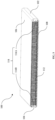
- FIG. 1 illustrates a flat tube 100 for a heat exchanger, in accordance with an embodiment of the present invention.
- FIG. 2 illustrates an exploded view of the flat tube 100 of FIG. 1 .
- the flat tube 100 for the heat exchanger comprises a fluid passage 110 through which a fluid flows, at least one inner fin 112 provided in the fluid passage 110 and at least one protrusion 114 protruding towards the inner fin 112, is provided in the fluid passage 110.
- the tube 100 for the heat exchanger can comprise a longitudinal axis L1 along which the flat tube 100 extends.
- the flat tube 100 can comprise a plurality of walls 102, 104, 106, 108 forming the fluid passage 110 through which the fluid flows.
- the flat tube 100 for the heat exchanger can comprise the at least one inner fin 112 provided in the fluid passage 110, wherein the fluid flows across the at least one inner fin 112 in the fluid passage 110.
- the flat tube 100 for the heat exchanger can comprise the at least one protrusion 114 protruding towards the inner fin 112, wherein the at least one protrusion 114 is protruding from the at least one wall 102, 104 from the plurality of walls 102, 104, 106, 108 of the flat tube 100.
- the plurality of walls 102, 104, 106, 108 of the flat tube 100 can have a polygon shape.
- the plurality of walls 102, 104, 106, 108 of the flat tube 100 can have a rectangle shape with a first wall 106 being substantially flat, a second wall 108 being substantially flat and parallel to the first wall 106 and two side walls 102, 104 joining the first wall 106 and the second wall 108.
- the inner fin 112 provided in the flat tube 100 can be meandering substantially transversely to the longitudinal axis L1 between the first wall 106 and the second wall 108 of the flat tube 100.
- the inner fin 112 provided in the flat tube 100 can be in contact with the first wall 106 and the second wall 108 of the flat tube 100.
- the inner fin 112 provided in the flat tube 100 cannot be in contact with at least one of the two side walls 102, 104 of the flat tube 100 due to some reasons like welding joint, reduced width upon forming and so on.
- the at least one protrusion 114 can be protruding from at least one of the two side walls 102, 104 of the flat tube 100. In another example, the at least one protrusion 114 can be protruding from one side wall 102 of the flat tube 100. In another example, the at least one protrusion 114 can be protruding from two side walls 102, 104 of the flat tube 100. In another aspect, the at least one protrusion 114 can be formed in the tube 100 by any type of manufacturing process. In another example, the at least one protrusion 114 and the tube 100 can be made as a single part. The at least one protrusion 114 can be formed in the tube 100 when the tube 100 is manufactured, for example, by forming process. In another example, the at least one protrusion 114 and the tube 100 can be made as separate parts and then can be connected together.
- FIG. 3 illustrates a sectional view of the flat tube 100 of FIG. 1 , at the plane A-A'.
- FIG. 4 illustrates an enlarged view of the protrusion 114 without the inner fin 112 of the flat tube 100 of FIG. 3 .
- FIG. 5 illustrates an enlarged view of the protrusion 114 with the inner fin 112 of the flat tube 100 of FIG. 3 .
- the at least one protrusion 114 can be configured to at least partially block the flow of fluid in the vicinity of the at least one of the two side walls 102, 104.
- the at least one protrusion 114 can significantly block a space between the inner fin 112 and the at least one of the two side walls 102, 104 of the flat tube 100.
- the at least one protrusion 114 protruding from the at least one of the two side walls 102, 104 of the flat tube 100 can comprise a tip portion that can be in contact with the inner fin 112.
- the tip portion of the at least one protrusion 114 protruding from the at least one of the two side walls 102, 104 of the tube 100 cannot be in contact with the inner fin 112.
- the at least one protrusion 114 can comprise a guiding means configured to guide the fluid towards the inner fin 112.
- the guiding means can have any shape adapted to guide the fluid towards the inner fin 112.
- the guiding means can have a curved shape.
- the fluid can be guided to flow across the fin 112 and not bypass the fin 112.
- the at least one protrusion 114 can have any shape that is protruding from the at least one of the two side walls 102, 104 of the flat tube 100.
- the at least one protrusion 114 can be a dimple.
- the at least one protrusion 114 can be a curved rib.
- a plurality of protrusions 114 can be protruding from the at least one of the two side walls 102, 104 of the flat tube 100. In another example, the plurality of protrusions 114 can be protruding from one side wall 102 of the flat tube 100. In another example, the plurality of protrusions 114 can be protruding from two side walls 102, 104 of the flat tube 100.
- the plurality of protrusions 114 can comprise a first plurality of protrusions 114A and a second plurality of protrusions 114B.
- the first plurality of protrusions 114A can be protruding from one side wall 102 of the flat tube 100 and the second plurality of protrusions 114B can be protruding from another side wall 104 of the flat tube 100.
- the first plurality of protrusions 114A can be identical or different compared to the second plurality of protrusions 114B.
- the first plurality of protrusions 114A can be identical to the second plurality of protrusions 114B in terms of characteristics such as shape, interval and so on.
- the first plurality of protrusions 114A can be different compared to the second plurality of protrusions 114B in terms of at least one characteristics such as shape, interval and so on.
- the flat tube 100 comprises at least one protrusion 114 protruding from the at least one of the two side walls 102, 104 of the flat tube 100.
- the at least one protrusion 114 comprises the guiding means configured to guide the fluid towards the inner fin 112. Therefore, the at least one protrusion 114 at least partially blocks the flow of the fluid in the vicinity of the at least one of the two side walls 102, 104, and guides the fluid towards the inner fin 112.
Landscapes
- Physics & Mathematics (AREA)
- Engineering & Computer Science (AREA)
- Geometry (AREA)
- Thermal Sciences (AREA)
- Mechanical Engineering (AREA)
- General Engineering & Computer Science (AREA)
- Heat-Exchange Devices With Radiators And Conduit Assemblies (AREA)
Abstract
A flat tube for a heat exchanger comprises a plurality of walls forming a fluid passage through which a fluid flows, at least one inner fin provided in the fluid passage and at least one protrusion protruding towards the inner fin, is provided in the fluid passage. The flat tube comprises a flat first wall, a flat second wall parallel to the first wall and two side walls joining the first wall and the second wall. The at least one inner fin is meandering between the first wall and the second wall of the flat tube. The at least one protrusion is protruding from the at least one of the two side walls and is configured to at least partially block the flow of fluid in the vicinity of the at least one of the two side walls.
Description
- The present invention relates to a tube for a heat exchanger. In particular, the present invention relates to a tube for a heat exchanger that comprises an inner fin.
- Generally, a heat exchanger comprises a plurality of flat tubes through which a first fluid flows. The first fluid flowing inside the flat tube exchanges heat with a second fluid flowing outside the flat tube. The flat tube comprises two longer sides joined by two shorter sides. The flat tube further comprises an inner fin to increase heat exchange of the first fluid with the second fluid. The inner fin provided inside the flat tube is in contact with the two longer sides of the flat tube. The inner fin provided inside the flat tube further may not be in contact with at least one of the two shorter sides of the flat tube due to some reasons like welding joint, shorter width upon forming and so on. Therefore, the first fluid may flow through a space between the inner fin and the at least one of the two shorter sides of the flat tube that is not in contact with the inner fin and consequently, the heat exchange performance is reduced.
- An objective of the present invention is to provide a flat tube for a heat exchanger that alleviates the problems in the prior arts. To be more precise, an objective of the present invention is to block a space between an inner fin and at least one of two short sides of the flat tube that is not in contact with the inner fin.
- Another objective of the present invention is to guide a fluid flowing in the flat tube towards the inner fin.
- To achieve the above objectives, the present invention herein provides a flat tube for a heat exchanger. The flat tube for the heat exchanger for a flow of a fluid comprising: a longitudinal axis along which the flat tube extends; a first wall being substantially flat, a second wall being substantially flat and parallel to the first wall and two side walls joining the first wall and the second wall, wherein the first wall, the second wall and the two side walls together form a hollow profile of the flat tube, thereby forming a fluid passage for the flow of the fluid; at least one inner fin provided in the fluid passage, is meandering substantially transversely to the longitudinal axis between the first wall and the second wall; and at least one protrusion protruding from the at least one of the two side walls, is configured to at least partially block the flow of fluid in the vicinity of the at least one of the two side walls.
- In one aspect, a tip portion of the at least one protrusion is in contact with the inner fin.
- In another aspect, the tip portion of the at least one protrusion is not in contact with the inner fin.
- In another aspect, the at least one protrusion comprises a guiding means configured to guide the fluid towards the inner fin.
- In another aspect, the guiding means has a curved shape.
- In another aspect, the at least one protrusion is provided proximate to an inlet of the flat tube.
- In another aspect, the at least one protrusion is a dimple.
- In another aspect, a plurality of protrusions are provided in the at least one of the two side walls.
- In another aspect, all protrusions from the plurality of protrusions are identical.
- In another aspect, at least one protrusion from the plurality of protrusions is different compared to other protrusions from the plurality of protrusions.
- In another embodiment, the present invention herein provides a heat exchanger. The heat exchanger comprises: at least one flat tube according to any one of the above embodiments.
- According to the above embodiments, the flat tube comprises at least one protrusion protruding from the at least one of the two side walls of the flat tube. Further, the at least one protrusion comprises the guiding means configured to guide the fluid towards the inner fin. Therefore, the at least one protrusion at least partially blocks the flow of fluid in the vicinity of the at least one of the two side walls, and guides the fluid towards the inner fin.
- Other characteristics, details and advantages of the invention can be inferred from the description of the invention hereunder. A more complete appreciation of the invention and many of the attendant advantages thereof will be readily obtained, as the same becomes better understood by reference to the following description when considered in connection with the accompanying figures, wherein:
-
FIG. 1 illustrates a flat tube for a heat exchanger, in accordance with an embodiment of the present invention; -
FIG. 2 illustrates an exploded view of the flat tube ofFIG. 1 ; -
FIG. 3 illustrates a sectional view of the flat tube ofFIG. 1 , at the plane A-A'; -
FIG. 4 illustrates an enlarged view of a protrusion without an inner fin of the flat tube ofFIG. 3 ; and -
FIG. 5 illustrates an enlarged view of the protrusion with the inner fin of the flat tube ofFIG. 3 . - It must be noted that the figures disclose the invention in a detailed enough way to be implemented, the figures helping to better define the invention, if need be. The invention should however not be limited to the embodiments disclosed in the description.
- In the present description, some elements or parameters may be indexed, such as a first element and a second element. In this case, unless stated otherwise, this indexation is only meant to differentiate and name elements that are similar but not identical. No idea of priority should be inferred from such indexation, as these may be switched without betraying the invention. Additionally, this indexation does not imply any order in mounting or use of the elements of the invention.
-
FIG. 1 illustrates aflat tube 100 for a heat exchanger, in accordance with an embodiment of the present invention.FIG. 2 illustrates an exploded view of theflat tube 100 ofFIG. 1 . Theflat tube 100 for the heat exchanger comprises afluid passage 110 through which a fluid flows, at least oneinner fin 112 provided in thefluid passage 110 and at least oneprotrusion 114 protruding towards theinner fin 112, is provided in thefluid passage 110. - In one embodiment, the
tube 100 for the heat exchanger can comprise a longitudinal axis L1 along which theflat tube 100 extends. Theflat tube 100 can comprise a plurality ofwalls fluid passage 110 through which the fluid flows. Theflat tube 100 for the heat exchanger can comprise the at least oneinner fin 112 provided in thefluid passage 110, wherein the fluid flows across the at least oneinner fin 112 in thefluid passage 110. Theflat tube 100 for the heat exchanger can comprise the at least oneprotrusion 114 protruding towards theinner fin 112, wherein the at least oneprotrusion 114 is protruding from the at least onewall walls flat tube 100. - In one aspect, the plurality of
walls flat tube 100 can have a polygon shape. In one example, the plurality ofwalls flat tube 100 can have a rectangle shape with afirst wall 106 being substantially flat, asecond wall 108 being substantially flat and parallel to thefirst wall 106 and twoside walls first wall 106 and thesecond wall 108. - In another aspect, the
inner fin 112 provided in theflat tube 100, can be meandering substantially transversely to the longitudinal axis L1 between thefirst wall 106 and thesecond wall 108 of theflat tube 100. In another example, theinner fin 112 provided in theflat tube 100, can be in contact with thefirst wall 106 and thesecond wall 108 of theflat tube 100. Theinner fin 112 provided in theflat tube 100, cannot be in contact with at least one of the twoside walls flat tube 100 due to some reasons like welding joint, reduced width upon forming and so on. - In another aspect, the at least one
protrusion 114 can be protruding from at least one of the twoside walls flat tube 100. In another example, the at least oneprotrusion 114 can be protruding from oneside wall 102 of theflat tube 100. In another example, the at least oneprotrusion 114 can be protruding from twoside walls flat tube 100. In another aspect, the at least oneprotrusion 114 can be formed in thetube 100 by any type of manufacturing process. In another example, the at least oneprotrusion 114 and thetube 100 can be made as a single part. The at least oneprotrusion 114 can be formed in thetube 100 when thetube 100 is manufactured, for example, by forming process. In another example, the at least oneprotrusion 114 and thetube 100 can be made as separate parts and then can be connected together. -
FIG. 3 illustrates a sectional view of theflat tube 100 ofFIG. 1 , at the plane A-A'.FIG. 4 illustrates an enlarged view of theprotrusion 114 without theinner fin 112 of theflat tube 100 ofFIG. 3 .FIG. 5 illustrates an enlarged view of theprotrusion 114 with theinner fin 112 of theflat tube 100 ofFIG. 3 . In another aspect, the at least oneprotrusion 114 can be configured to at least partially block the flow of fluid in the vicinity of the at least one of the twoside walls protrusion 114 can significantly block a space between theinner fin 112 and the at least one of the twoside walls flat tube 100. In another example, the at least oneprotrusion 114 protruding from the at least one of the twoside walls flat tube 100, can comprise a tip portion that can be in contact with theinner fin 112. In another example, the tip portion of the at least oneprotrusion 114 protruding from the at least one of the twoside walls tube 100, cannot be in contact with theinner fin 112. - In another aspect, the at least one
protrusion 114 can comprise a guiding means configured to guide the fluid towards theinner fin 112. In another aspect, the guiding means can have any shape adapted to guide the fluid towards theinner fin 112. In another example, the guiding means can have a curved shape. As a result, the fluid can be guided to flow across thefin 112 and not bypass thefin 112. In another aspect, the at least oneprotrusion 114 can have any shape that is protruding from the at least one of the twoside walls flat tube 100. In another example, the at least oneprotrusion 114 can be a dimple. In another example, the at least oneprotrusion 114 can be a curved rib. - In another aspect, a plurality of
protrusions 114 can be protruding from the at least one of the twoside walls flat tube 100. In another example, the plurality ofprotrusions 114 can be protruding from oneside wall 102 of theflat tube 100. In another example, the plurality ofprotrusions 114 can be protruding from twoside walls flat tube 100. - In another aspect, the plurality of
protrusions 114 can comprise a first plurality ofprotrusions 114A and a second plurality ofprotrusions 114B. In another example, the first plurality ofprotrusions 114A can be protruding from oneside wall 102 of theflat tube 100 and the second plurality ofprotrusions 114B can be protruding from anotherside wall 104 of theflat tube 100. In another aspect, the first plurality ofprotrusions 114A can be identical or different compared to the second plurality ofprotrusions 114B. In another example, the first plurality ofprotrusions 114A can be identical to the second plurality ofprotrusions 114B in terms of characteristics such as shape, interval and so on. In another example, the first plurality ofprotrusions 114A can be different compared to the second plurality ofprotrusions 114B in terms of at least one characteristics such as shape, interval and so on. - According to the above-described embodiments, the
flat tube 100 comprises at least oneprotrusion 114 protruding from the at least one of the twoside walls flat tube 100. Further, the at least oneprotrusion 114 comprises the guiding means configured to guide the fluid towards theinner fin 112. Therefore, the at least oneprotrusion 114 at least partially blocks the flow of the fluid in the vicinity of the at least one of the twoside walls inner fin 112. - All the above-described embodiments are just to explain the present invention while more embodiments and combinations thereof might exist. Hence, the present invention should not be limited to the above-described embodiments alone.
Claims (11)
- A flat tube (100) for a heat exchanger for a flow of a fluid comprising:a longitudinal axis (L1) along which the flat tube (100) extends;a first wall (106) being substantially flat, a second wall (108) being substantially flat and parallel to the first wall (106) and two side walls (102, 104) joining the first wall (106) and the second wall (108), wherein the first wall (106), the second wall (108) and the two side walls (102, 104) together form a hollow profile of the flat tube (100), thereby forming a fluid passage (110) for the flow of the fluid;at least one inner fin (112) provided in the fluid passage (110), is meandering substantially transversely to the longitudinal axis (L1) between the first wall (106) and the second wall (108); andat least one protrusion (114) protruding from the at least one of the two side walls (102, 104), is configured to at least partially block the flow of fluid in the vicinity of the at least one of the two side walls (102, 104).
- The flat tube (100) as claimed in preceding claim, wherein a tip portion of the at least one protrusion (114) is in contact with the inner fin (112).
- The tube (100) as claimed in claim 1, wherein the tip portion of the at least one protrusion (114) is not in contact with the inner fin (112).
- The flat tube (100) as claimed in claim 2 or 3, wherein the at least one protrusion (114) comprises a guiding means configured to guide the fluid towards the inner fin (112).
- The flat tube (100) as claimed in preceding claim, wherein the guiding means has a curved shape.
- The flat tube (100) as claimed in any one of preceding claims, wherein the at least one protrusion (114) is provided proximate to an inlet of the flat tube (100).
- The flat tube (100) as claimed in any one of preceding claims, wherein the at least one protrusion (114) is a dimple.
- The flat tube (100) as claimed in any one of preceding claims, wherein a plurality of protrusions (114) are provided in the at least one of the two side walls (102, 104).
- The flat tube (100) as claimed in preceding claim, wherein all protrusions (114A, 114B) from the plurality of protrusions (114) are identical.
- The flat tube (100) as claimed in claim 8, wherein at least one protrusion (114A) from the plurality of protrusions (114) is different compared to other protrusions (114B) from the plurality of protrusions (114).
- A heat exchanger comprising at least one flat tube (100) according to any of the preceding claims.
Priority Applications (1)
| Application Number | Priority Date | Filing Date | Title |
|---|---|---|---|
| EP23209181.9A EP4553439A1 (en) | 2023-11-10 | 2023-11-10 | A tube for a heat exchanger |
Applications Claiming Priority (1)
| Application Number | Priority Date | Filing Date | Title |
|---|---|---|---|
| EP23209181.9A EP4553439A1 (en) | 2023-11-10 | 2023-11-10 | A tube for a heat exchanger |
Publications (1)
| Publication Number | Publication Date |
|---|---|
| EP4553439A1 true EP4553439A1 (en) | 2025-05-14 |
Family
ID=88779789
Family Applications (1)
| Application Number | Title | Priority Date | Filing Date |
|---|---|---|---|
| EP23209181.9A Withdrawn EP4553439A1 (en) | 2023-11-10 | 2023-11-10 | A tube for a heat exchanger |
Country Status (1)
| Country | Link |
|---|---|
| EP (1) | EP4553439A1 (en) |
Citations (4)
| Publication number | Priority date | Publication date | Assignee | Title |
|---|---|---|---|---|
| JP2004061032A (en) * | 2002-07-30 | 2004-02-26 | Toyo Radiator Co Ltd | Flat tube for heat exchanger having inner fin |
| JP2005214511A (en) * | 2004-01-29 | 2005-08-11 | Calsonic Kansei Corp | Heat exchanger |
| JP2012229853A (en) * | 2011-04-26 | 2012-11-22 | Showa Denko Kk | Heat exchanger |
| EP3521746B1 (en) * | 2018-02-06 | 2023-04-19 | Valeo Autosystemy SP. Z.O.O. | A flat tube for a heat exchanger |
-
2023
- 2023-11-10 EP EP23209181.9A patent/EP4553439A1/en not_active Withdrawn
Patent Citations (4)
| Publication number | Priority date | Publication date | Assignee | Title |
|---|---|---|---|---|
| JP2004061032A (en) * | 2002-07-30 | 2004-02-26 | Toyo Radiator Co Ltd | Flat tube for heat exchanger having inner fin |
| JP2005214511A (en) * | 2004-01-29 | 2005-08-11 | Calsonic Kansei Corp | Heat exchanger |
| JP2012229853A (en) * | 2011-04-26 | 2012-11-22 | Showa Denko Kk | Heat exchanger |
| EP3521746B1 (en) * | 2018-02-06 | 2023-04-19 | Valeo Autosystemy SP. Z.O.O. | A flat tube for a heat exchanger |
Similar Documents
| Publication | Publication Date | Title |
|---|---|---|
| JP4175443B2 (en) | Heat exchanger | |
| US6523603B2 (en) | Double heat exchanger with condenser and radiator | |
| KR101488131B1 (en) | Tube for heat exchanger | |
| KR980010317A (en) | FLAT TUBES FOR HEAT EXCHANGER | |
| US20080283229A1 (en) | Heat exchanger | |
| US9726439B2 (en) | Tube and heat exchanger provided with tube | |
| JP2007139416A (en) | Metal plate for producing flat tube, flat tube, and its manufacturing method | |
| EP3907459A1 (en) | A heat exchanger | |
| JP3664783B2 (en) | Condenser | |
| KR100336847B1 (en) | Header and tank structure of heat exchanger | |
| EP4160130A1 (en) | Heat exchanger | |
| CN115667834A (en) | Header plate structure of heat exchanger | |
| CN112739972B (en) | Compliant B-tube for heat sink applications | |
| JP4418246B2 (en) | Heat exchanger | |
| JP2018155433A (en) | HEAT EXCHANGER AND HEAT EXCHANGER MANUFACTURING METHOD | |
| JP2003114094A (en) | Heat exchanger header | |
| JP2007292401A (en) | Refrigerant condenser with liquid receiver | |
| JPH09264689A (en) | Heat exchanger | |
| JP4329096B2 (en) | Heat exchanger and manufacturing method thereof | |
| JP7485993B1 (en) | Heat exchanger | |
| JP2001056190A (en) | Tube for heat exchanger | |
| EP4339542A1 (en) | A reinforcing insert for a heat exchanger tube | |
| KR102692185B1 (en) | Heat exchanger | |
| JPH03230834A (en) | Manufacture of heat exchanger | |
| JP2010085024A (en) | Heat exchanger |
Legal Events
| Date | Code | Title | Description |
|---|---|---|---|
| PUAI | Public reference made under article 153(3) epc to a published international application that has entered the european phase |
Free format text: ORIGINAL CODE: 0009012 |
|
| STAA | Information on the status of an ep patent application or granted ep patent |
Free format text: STATUS: THE APPLICATION HAS BEEN PUBLISHED |
|
| AK | Designated contracting states |
Kind code of ref document: A1 Designated state(s): AL AT BE BG CH CY CZ DE DK EE ES FI FR GB GR HR HU IE IS IT LI LT LU LV MC ME MK MT NL NO PL PT RO RS SE SI SK SM TR |
|
| STAA | Information on the status of an ep patent application or granted ep patent |
Free format text: STATUS: THE APPLICATION IS DEEMED TO BE WITHDRAWN |
|
| 18D | Application deemed to be withdrawn |
Effective date: 20251115 |