EP4553436A1 - A heat exchanger - Google Patents
A heat exchanger Download PDFInfo
- Publication number
- EP4553436A1 EP4553436A1 EP23208484.8A EP23208484A EP4553436A1 EP 4553436 A1 EP4553436 A1 EP 4553436A1 EP 23208484 A EP23208484 A EP 23208484A EP 4553436 A1 EP4553436 A1 EP 4553436A1
- Authority
- EP
- European Patent Office
- Prior art keywords
- pass
- fluid
- section
- channel
- heat exchanger
- Prior art date
- Legal status (The legal status is an assumption and is not a legal conclusion. Google has not performed a legal analysis and makes no representation as to the accuracy of the status listed.)
- Withdrawn
Links
Images



Classifications
-
- F—MECHANICAL ENGINEERING; LIGHTING; HEATING; WEAPONS; BLASTING
- F28—HEAT EXCHANGE IN GENERAL
- F28F—DETAILS OF HEAT-EXCHANGE AND HEAT-TRANSFER APPARATUS, OF GENERAL APPLICATION
- F28F9/00—Casings; Header boxes; Auxiliary supports for elements; Auxiliary members within casings
- F28F9/02—Header boxes; End plates
- F28F9/0246—Arrangements for connecting header boxes with flow lines
-
- F—MECHANICAL ENGINEERING; LIGHTING; HEATING; WEAPONS; BLASTING
- F28—HEAT EXCHANGE IN GENERAL
- F28D—HEAT-EXCHANGE APPARATUS, NOT PROVIDED FOR IN ANOTHER SUBCLASS, IN WHICH THE HEAT-EXCHANGE MEDIA DO NOT COME INTO DIRECT CONTACT
- F28D9/00—Heat-exchange apparatus having stationary plate-like or laminated conduit assemblies for both heat-exchange media, the media being in contact with different sides of a conduit wall
- F28D9/0031—Heat-exchange apparatus having stationary plate-like or laminated conduit assemblies for both heat-exchange media, the media being in contact with different sides of a conduit wall the conduits for one heat-exchange medium being formed by paired plates touching each other
- F28D9/0043—Heat-exchange apparatus having stationary plate-like or laminated conduit assemblies for both heat-exchange media, the media being in contact with different sides of a conduit wall the conduits for one heat-exchange medium being formed by paired plates touching each other the plates having openings therein for circulation of at least one heat-exchange medium from one conduit to another
- F28D9/005—Heat-exchange apparatus having stationary plate-like or laminated conduit assemblies for both heat-exchange media, the media being in contact with different sides of a conduit wall the conduits for one heat-exchange medium being formed by paired plates touching each other the plates having openings therein for circulation of at least one heat-exchange medium from one conduit to another the plates having openings therein for both heat-exchange media
-
- F—MECHANICAL ENGINEERING; LIGHTING; HEATING; WEAPONS; BLASTING
- F28—HEAT EXCHANGE IN GENERAL
- F28D—HEAT-EXCHANGE APPARATUS, NOT PROVIDED FOR IN ANOTHER SUBCLASS, IN WHICH THE HEAT-EXCHANGE MEDIA DO NOT COME INTO DIRECT CONTACT
- F28D9/00—Heat-exchange apparatus having stationary plate-like or laminated conduit assemblies for both heat-exchange media, the media being in contact with different sides of a conduit wall
- F28D9/0093—Multi-circuit heat-exchangers, e.g. integrating different heat exchange sections in the same unit or heat-exchangers for more than two fluids
Definitions
- the object of the present application is a heat exchanger, in particular a condenser or a gas cooler, for use inter alia in automobile air-conditioning systems.
- Known solutions referred to the subject of the application relate to plate heat exchangers.
- Such heat exchangers are formed by a suitably shaped thin plates forming the heat exchange surface.
- the plates are usually stamped or extruded to form a pattern of bulges and recesses on their surface.
- the plates are also provided with openings in appropriate positions, which, after sealing and forming a packet of plates, form inlet and outlet channels for the media participating in heat transfer. It is to be noted that such channels are further in the application referred to as channels substantially perpendicular to the general plane formed by the plates in which the openings are formed. In other words, channels formed by openings in plates are different from the channels, or rather flow pathways formed in-between the plates.
- the essence of the plate heat exchangers is that the flow pathways of media (such as fluids) are interleaved, i.e. the consecutive spaces between the plates are alternatively used for heat-emitting medium and heat-receiving medium.
- media such as fluids
- channel systems formed by the extrusions of adjacent plates cause the breakdown of the stream of each medium on many smaller streams and the introduction of the turbulence in the flow stream, resulting in better heat transfer between the media.
- Said plate heat exchangers can have various applications, among others, they can serve as evaporators, WCDS (water cooled condensers) and IHX (internal heat exchangers).
- the important matter is suitable flow control separately for each of these media, i.e. to reduce the flow speed, to introduce respective turbulences in a flow stream and its suitable dividing while maintaining low pressure drop of the flowing medium.
- the prior art heat exchangers suffer from the high entry speed of the fluid into the first pass, where the density of the fluid is the lowest. Thus, there is a need to improve the overall performance of the heat exchanger. There is a need to reduce the pressure drops in the heat exchanger. Consequently, there is a need to improve the distribution of the fluid in the heat exchanger, in particular at the entry thereto.
- the object of the invention is, among others, a heat exchanger for a heat exchange between a first fluid and at least second fluid comprising: -a plurality of flat plates stacked together to form a core for circulation of the first fluid therein, wherein the core comprises a first pass called ingress pass, at least one second section called middle pass, and a third section called egress pass, wherein the middle pass is fluidly connected directly to the ingress pass, and the egress pass is fluidly connected indirectly to the middle pass, wherein the first section comprises at least a first channel adapted to distribute the first fluid in the first section, a second channel fluidly connecting the second section and the first section, and at least a third channel fluidly connected at least to the second section, wherein the total hydraulic diameter of the first channel is greater than the hydraulic diameter of any of the second channel or the third channel.
- the first channel comprises a first conduit and a second conduit, the conduits extending substantially in the stacking direction of the plates.
- first conduit and a second conduit comprise a substantially circular cross- section, wherein the hydraulic diameter of the first conduit is equal to the hydraulic diameter of the second conduit.
- first conduit and a second conduit comprise a substantially circular cross- section, wherein the hydraulic diameter of the first conduit is greater than the hydraulic diameter of the second conduit.
- the egress pass remains in indirect fluidal communication with the middle pass so that the middle pass is configured to convey the first fluid, wherein the egress pass is configured to convey the second fluid, the second fluid being different from the first fluid.
- the first fluid in the middle pass flows in the opposite direction with respect to the second fluid flowing in the egress pass.
- said heat exchanger comprises a fourth section called coolant section, said coolant section being configured for circulation of the third fluid therein, wherein the coolant section extends across the entire heat exchanger, so that the fourth section may exchange the heat with all other sections.
- the coolant section is divided into several substantially U-shaped sections.
- the first and the second fluid is a refrigerant, whereas the third fluid is a coolant.
- the core is fluidly connected with the ingress block, wherein in terms of hydraulic diameter the ingress bloc is complementary to the first channel.
- the ingress block comprises a first ingress block opening, a second ingress block opening and a third ingress block opening, wherein the first and the second ingress block openings are associated with the first conduit and the second conduit, respectively, and the third ingress block opening is configured to be fixed to a jumper line.
- the ingress pass and the middle pass are divided by a first baffle plate, the first baffle plate being configured to block the flow of the first fluid through the first channel and direct it in-between the plates of the core through the first pass towards the second channel.
- the egress pass and the middle pass are divided by a second baffle plate, the second baffle plate being configured to block the flow of the first fluid through the second channel and direct it in-between the plates of the core through the second pass towards the third channel, the second baffle plated being further configured to block the flow of the first fluid through a fifth channel and direct it in-between the plates of the core through the egress pass towards a sixth channel.
- Another object of the invention is a motor vehicle comprising at least one heat exchanger according to any of the preceding claims.
- the overall performance of the heat exchanger may not only be improved, but also controlled according to the design and needs. Needless to say this invention allows lowering the pressure drop inside the heat exchanger without increasing the external dimensions thereof.
- the invention concerns, among other a heat exchanger 1 for a motor vehicle.
- the invention concerns a plate-type heat exchanger 1, for example, a water cooled condenser (WCDS).
- the heat exchanger 1 may be configured for a heat exchange between a first fluid and at least second fluid.
- the heat exchange between the fluids may be carried out by the means of plurality of flat plates 10 stacked together to form a core 100 for circulation of the first fluid therein.
- the flat plates 10 are usually made from metallic material.
- the thickness of all the plates may be the same, wherein said thickness is measures in perpendicular with respect to the general plane of the flat plate 10. Alternatively, the thickness of two consecutive flat plates 10 may be different.
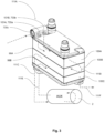
- Fig. 1 shows a perspective view of the heat exchanger showing refrigerant inlet with jumper line, coolant inlet and coolant outlet whereas Fig. 2 shows a bottom part of the heat exchanger shown in Fig. 1 , wherein another view on the jumper line with refrigerant inlet is present, as well as the refrigerant outlet and refrigerant connection to auxiliary device such as bottle.
- the flat plates 10 stacked together to form a core 100 comprise multiple components which in the picture may be blurry and it would be difficult to show other technical features. Thus, for the sake of clarity, the core 100 is simplified in the remaining figures.
- the core 100 may comprise a first section 100A called ingress pass.
- the ingress pass 100A or in general any "pass” or “section” may be regarded as the part of the core in which the fluid, for example the first fluid, flows in the same direction and in the same sense.
- the core 100 may comprise at least one second section 100B called middle pass, and a third section 100C called egress pass.
- the middle pass 100B is fluidly connected directly to the ingress pass 100A
- the egress pass 100C is fluidly connected indirectly to the middle pass 100B.
- the term directly means that the middle pass 100B is arranged subsequently to the ingress pass 100A and that they are fluidly connected by some means. In other words, in case of direct connection no other pass or component is located between ingress pass 100A and middle pass 100B.
- the egress pass 100C however is fluidly connected with the middle pass 100B indirectly, i.e. there is some other subcomponent on the path of the fluid. As shown in figures, the middle pass 100B is connected directly with a third channel 111C.
- the third channel 111C runs through the egress pass 100C (without fluidal communication therewith) in order to enable direct fluidal communication between the heat exchanger 1 to an auxiliary device 2 (AUX device).
- auxiliary device 2 may be regarded as the subcomponent which is not at the first glance structurally integrated with the heat exchanger 1. This definition however, does not exclude functional connection between the heat exchanger 1 and the auxiliary device 2.
- the AUX device 2 may be for instance a receiver drier (bottle). It should be noted that the AUX device 2 may or may not change the properties of the first fluid flowing therein.
- the fluid entering the AUX device through the third channel 111C is the first fluid coming from, inter alia, mille pass 100B whereas the fluid exiting the AUX device may be regarded as the second fluid, due to aforementioned potential change in its properties.
- the egress pass 100C is not filled by the first fluid, but by the second fluid despite the fact the egress pass 100C, the AUX device 2 and the first and second passes 100A, 100B belong to the same loop.
- the ingress pass 100A and the egress pass 100C are named functionally, i.e. the ingress pass is the first pass to allow the fluid to circulate within the heat exchanger 1 whereas the egress pass 100C is the last pass that conveys the fluid within the core 100 of the heat exchanger 1.
- the middle pass 100B may thus comprise several sub-sections fluidly connected between each other so that the U-flow is provided between consecutive sub-sections of said middle passes 100B.
- the U-flow may be provided between the first section 100A and the second section 100B and the second section 100B and the third section 100C.
- the first section 100A comprises at least a first channel 111A adapted to distribute the first fluid in the first section 100A, a second channel 111Bfluidly connecting the second section 100B and the first section 100A, and at least a third channel 111C fluidly connected at least to the second section 100B.
- the first channel 111A the second channel 111B and the third channel 111C may be regarded as first manifold 111A, second manifold 111B and a third manifold 111C, respectively.
- the total hydraulic diameter of the first channel 111A is greater than the total hydraulic diameter of any of the second channel 111B or the third channel 111C. This allows the first fluid to be introduced into the first section 100A at the greater flow rate, compared to prior art heat exchangers. Overall, the greater hydraulic diameter of the first channel 111A allows more even and quick distribution of the first fluid at the entry pass to the heat exchanger what provides more uniform distribution of the first fluid, in particular in the first section 100A.
- the first channel 111A may be in a form of a first conduit 101A and a second conduit 101B, the conduits 101A, 101B extending substantially in the stacking direction of the plates 10.
- the term "conduit” refers to the hollow space provided in the flat plate which allows circulation of the first fluid into the first section 100A.
- This hollow space may be of substantially circular cross-section.
- the hollow space may comprise a cross-section of any other shape.
- first conduit 101A and a second conduit 101B comprise a substantially circular cross- section, wherein the hydraulic diameter of the first conduit 101A is equal to the hydraulic diameter of the second conduit 101B. This allows the first fluid to evenly fill the first channel 111A, so that the fluid is distributed in the first section 100A at the same flow rate through both conduits 101A 101B.
- the hydraulic diameter of the first conduit 101A may be greater than the hydraulic diameter of the second conduit 101B.
- the second conduit 101B comprises a hydraulic diameter which is greater than the hydraulic diameter of the first conduit 101A the observed technical effect is likely to be the same.
- Fig. 4 shows a standalone plate 10 with apertures which in combination with other plates 10 may form the channels 111A, 111B, 111C or conduits 101A, 101B, depending on the location of the plate 10 in the heat exchanger 1, or else, in which of the section 100A, 100B or 100C said aperture is located.
- the fluid may be directed through said section 100A partially.
- one of the conduits for example the first conduit 101A may extend through all the plates 10 forming the first section 100A
- the other conduit for example the second conduit 101B may extend only through some of the plates 10 forming the first section 100A.
- the first conduit 101A may be longer than the second conduit 101B, wherein the length of said conduits 101A, 101B is measured in parallel with respect to the stacking direction of the plates 10.
- the egress pass 100C is not connected directly with the middle pass 100B so that the middle pass 100B is configured to convey the first fluid, wherein the egress pass 100C is configured to convey the second fluid, as explained in previous paragraphs.
- the second fluid may be different from the first fluid which means one fluid may be of different properties than the other. For instance, viscosity, pressure or phase of one fluid may different from the same parameter of other fluid.
- the egress pass 100C will be in fact the sub-cooling sections of the heat exchanger 1.
- the first fluid in the middle pass 100B flows in the opposite direction with respect to the second fluid flowing in the egress pass 1 00C. This allows the greater heat exchange between the fluids flowing in respective passes 100B, 100C.
- the first fluid in the middle pass 100B may flow in the same direction with respect to the second fluid flowing in the egress pass 100C.
- the heat exchanger 1 may comprise a loop for a coolant. Therefore, the heat exchanger 1 may further comprise a fourth section 100D called coolant section.
- the coolant section may be configured for circulation of the third fluid therein.
- the coolant section 100D extends across the entire heat exchanger 1, so that the fourth section 100D may exchange the heat with all other sections 100A, 100B, 100C.
- the fourth section 100D and the fluid path for the third fluid in general is fluidly insulated from the first, second and third sections 100A, 100B, 100C, accordingly.
- the fluidly insulated means that mixing of the third fluid, i.e. coolant, with any other fluid is not allowed.
- the coolant section may also be divided into one or several substantially U-shaped sections.
- I-flow of the coolant is also envisaged, although not shown in the figures.
- the number and location of U-shaped sections may determine the location and arrangement of the inlet and outlet spigots for the coolant.
- the spigots are required to connect the coolant flow path with the rest of the coolant loop in the vehicle. It is also envisaged that the coolant lines are directly brazed to the heat exchanger 1.
- the first and the second fluid is may be a refrigerant, such as classical refrigerants such as R134a, R1234yf.
- the third fluid may be a coolant or a water.
- the heat exchanger 1 may be connected to at least the refrigerant loop and the coolant loop. In order to facilitate the connection or to meet the customer's requirements, the heat exchanger 1 may comprise connection blocks.
- the core 100 may be fluidly connected with an ingress block 700.
- the ingress block 700 may be complementary to the first channel 111A. It means that the cavity in the ingress block 700 and the first channel 111A are configured to provide continuous channel for the first fluid.
- the ingress block 700 may comprise a first ingress block opening 700a, a second ingress block opening 700b and a third ingress block opening 700c.
- the first and the second ingress block openings 700a, 700b may be associated with the first conduit 101A and the second conduit 101B, respectively, and the third ingress block opening 700c is configured to be fixed to a jumper line 750, as shown in figs 1 and 2 .
- the jumper line 750 may be fixed directly to the refrigerant loop or it may comprise an interface block 760 at the end opposite to the ingress block 700, as shown in figs 1 and 2 .
- the ingress pass 100A from the middle pass 100B, the ingress pass 100A and the middle pass 100B may be divided by a first baffle plate 99A.
- the the first baffle plate 99A may be configured to block the flow of the first fluid through the first channel 111A and direct it in-between the plates 10 of the core 100 through the first pass 100A towards the second channel 111B.
- the baffle plates 99A may comprise less apertures than the plates 10 shown in Fig.4 .
- the egress pass 100C and the middle pass 100B may be divided by a second baffle plate 99B.
- the second baffle plate 99B may be configured to block the flow of the first fluid through the second channel 111B and direct it in-between the plates 10 of the core 100 through the second pass 100B towards the second channel 111B.
- the second baffle plated 99B may be further configured to block the flow of the first fluid through a fifth channel 111E and direct it in-between the plates 10 of the core 100 through the egress pass 100C towards a sixth channel 111F.
- the invention further discloses a motor vehicle comprising at least one heat exchanger 1 according to any of the preceding claims.
- motor vehicle should not be limiting and the heat exchanger may be applied on motor vehicles comprising internal combustion engine, hybrid vehicles, and electric vehicles.
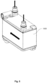
- Fig. 5 shows an exemplary third fluid flow path.
- the coolant may flow from one spigot to the other, in so-called I-flow pattern. It should be noted that the most effective heat exchange is when the third fluid flows in opposite direction with respect to the first and/or the second fluid. Other flow patterns for the third fluid are also envisaged.
Landscapes
- Engineering & Computer Science (AREA)
- Physics & Mathematics (AREA)
- Thermal Sciences (AREA)
- Mechanical Engineering (AREA)
- General Engineering & Computer Science (AREA)
- Heat-Exchange Devices With Radiators And Conduit Assemblies (AREA)
Abstract
The object of the invention is, among others, a heat exchanger (1) for a heat exchange between a first fluid and at least second fluid comprising: -a plurality of flat plates (10) stacked together to form a core (100) for circulation of the first fluid therein, wherein the core (100) comprises a first pass (100A) called ingress pass, at least one second section (100B) called middle pass, and a third section (100C) called egress pass, wherein the middle pass is fluidly connected directly to the ingress pass, and the egress pass is fluidly connected indirectly to the middle pass, wherein the first section (100A) comprises at least a first channel (111A) adapted to distribute the first fluid in the first section (100A), a second channel (111B) fluidly connecting the second section (100B) and the first section (100A), and at least a third channel (111C) fluidly connected at least to the second section (100B), wherein the total hydraulic diameter of the first channel (111A) is greater than the hydraulic diameter of any of the second channel (111B) or the third channel (111C). The invention also concerns a motor vehicle comprising such a heat exchanger.
Description
- The object of the present application is a heat exchanger, in particular a condenser or a gas cooler, for use inter alia in automobile air-conditioning systems.
- Known solutions referred to the subject of the application relate to plate heat exchangers. Such heat exchangers are formed by a suitably shaped thin plates forming the heat exchange surface. The plates are usually stamped or extruded to form a pattern of bulges and recesses on their surface. Forming a stack of plates and their tight connection, for example by welding, soldering or screwing between outer protection panels, forms the channel systems between the plates.
- The plates are also provided with openings in appropriate positions, which, after sealing and forming a packet of plates, form inlet and outlet channels for the media participating in heat transfer. It is to be noted that such channels are further in the application referred to as channels substantially perpendicular to the general plane formed by the plates in which the openings are formed. In other words, channels formed by openings in plates are different from the channels, or rather flow pathways formed in-between the plates.
- The essence of the plate heat exchangers is that the flow pathways of media (such as fluids) are interleaved, i.e. the consecutive spaces between the plates are alternatively used for heat-emitting medium and heat-receiving medium. In addition, channel systems formed by the extrusions of adjacent plates, cause the breakdown of the stream of each medium on many smaller streams and the introduction of the turbulence in the flow stream, resulting in better heat transfer between the media.
- Said plate heat exchangers can have various applications, among others, they can serve as evaporators, WCDS (water cooled condensers) and IHX (internal heat exchangers).
- It should be noted that in the case of a heat exchanger in which the heat emitting refrigerant is a gas changing its physical state to a liquid as a result of the cooling, while the heat-receiving coolant is a liquid, the important matter is suitable flow control separately for each of these media, i.e. to reduce the flow speed, to introduce respective turbulences in a flow stream and its suitable dividing while maintaining low pressure drop of the flowing medium.
- Due to the different physical properties of the media participating in heat exchange, it is necessary to form their flow paths through a heat exchanger in different ways so as to obtain the most efficient heat exchange there between.
- The above-described solution of heat exchangers comprising a packet of pressed metal sheets is not favorable to an independent shaping of the channel system for the gaseous medium and liquid medium due to the fact that the extrusion of a metal sheet influences simultaneously both on a shape of its surface which forms a channel system for the gaseous refrigerant as well as on the surface interacting with a liquid coolant. Therefore, in such system it is not possible any influence on the shape of the flow path of one medium independently of the shape of the second refrigerant flow path.
- The prior art heat exchangers suffer from the high entry speed of the fluid into the first pass, where the density of the fluid is the lowest. Thus, there is a need to improve the overall performance of the heat exchanger. There is a need to reduce the pressure drops in the heat exchanger. Consequently, there is a need to improve the distribution of the fluid in the heat exchanger, in particular at the entry thereto.
- The object of the invention is, among others, a heat exchanger for a heat exchange between a first fluid and at least second fluid comprising: -a plurality of flat plates stacked together to form a core for circulation of the first fluid therein, wherein the core comprises a first pass called ingress pass, at least one second section called middle pass, and a third section called egress pass, wherein the middle pass is fluidly connected directly to the ingress pass, and the egress pass is fluidly connected indirectly to the middle pass, wherein the first section comprises at least a first channel adapted to distribute the first fluid in the first section, a second channel fluidly connecting the second section and the first section, and at least a third channel fluidly connected at least to the second section, wherein the total hydraulic diameter of the first channel is greater than the hydraulic diameter of any of the second channel or the third channel.
- Advantageously, the first channel comprises a first conduit and a second conduit, the conduits extending substantially in the stacking direction of the plates.
- Advantageously, the first conduit and a second conduit comprise a substantially circular cross- section, wherein the hydraulic diameter of the first conduit is equal to the hydraulic diameter of the second conduit.
- Advantageously, the first conduit and a second conduit comprise a substantially circular cross- section, wherein the hydraulic diameter of the first conduit is greater than the hydraulic diameter of the second conduit.
- Advantageously, wherein the egress pass remains in indirect fluidal communication with the middle pass so that the middle pass is configured to convey the first fluid, wherein the egress pass is configured to convey the second fluid, the second fluid being different from the first fluid.
- Advantageously, the first fluid in the middle pass flows in the opposite direction with respect to the second fluid flowing in the egress pass.
- Advantageously, said heat exchanger comprises a fourth section called coolant section, said coolant section being configured for circulation of the third fluid therein, wherein the coolant section extends across the entire heat exchanger, so that the fourth section may exchange the heat with all other sections.
- Advantageously, the coolant section is divided into several substantially U-shaped sections.
- Advantageously, the first and the second fluid is a refrigerant, whereas the third fluid is a coolant.
- Advantageously, the core is fluidly connected with the ingress block, wherein in terms of hydraulic diameter the ingress bloc is complementary to the first channel.
- Advantageously, the ingress block comprises a first ingress block opening, a second ingress block opening and a third ingress block opening, wherein the first and the second ingress block openings are associated with the first conduit and the second conduit, respectively, and the third ingress block opening is configured to be fixed to a jumper line.
- Advantageously, the ingress pass and the middle pass are divided by a first baffle plate, the first baffle plate being configured to block the flow of the first fluid through the first channel and direct it in-between the plates of the core through the first pass towards the second channel.
- Advantageously, the egress pass and the middle pass are divided by a second baffle plate, the second baffle plate being configured to block the flow of the first fluid through the second channel and direct it in-between the plates of the core through the second pass towards the third channel, the second baffle plated being further configured to block the flow of the first fluid through a fifth channel and direct it in-between the plates of the core through the egress pass towards a sixth channel.
- Another object of the invention is a motor vehicle comprising at least one heat exchanger according to any of the preceding claims.
- By improving the distribution of the first fluid in the ingress pass the overall performance of the heat exchanger may not only be improved, but also controlled according to the design and needs. Needless to say this invention allows lowering the pressure drop inside the heat exchanger without increasing the external dimensions thereof.
- Examples of the invention will be apparent from and described in detail with reference to the accompanying drawings, in which:
-
Fig. 1 shows a perspective view of the heat exchanger showing refrigerant inlet with jumper line, coolant inlet and coolant outlet. -
Fig. 2 shows a bottom part of the heat exchanger shown inFig. 1 , wherein another view on the jumper line with refrigerant inlet is present, as well as the refrigerant outlet and refrigerant connection to auxiliary device such as bottle. -
Fig. 3 shows a simplified perspective view ofFig.1 , wherein the heat exchanger is connected to auxiliary device, such as bottle. -
Fig. 4 shows an exemplary standalone plate forming the core of the heat exchanger. -
Fig. 5 shows another perspective view of the heat exchanger showing flow pattern for the coolant fluid. - The invention concerns, among other a
heat exchanger 1 for a motor vehicle. In particular, the invention concerns a plate-type heat exchanger 1, for example, a water cooled condenser (WCDS). Theheat exchanger 1 may be configured for a heat exchange between a first fluid and at least second fluid. - The heat exchange between the fluids may be carried out by the means of plurality of
flat plates 10 stacked together to form acore 100 for circulation of the first fluid therein. Theflat plates 10 are usually made from metallic material. The thickness of all the plates may be the same, wherein said thickness is measures in perpendicular with respect to the general plane of theflat plate 10. Alternatively, the thickness of two consecutiveflat plates 10 may be different. -
Fig. 1 shows a perspective view of the heat exchanger showing refrigerant inlet with jumper line, coolant inlet and coolant outlet whereasFig. 2 shows a bottom part of the heat exchanger shown inFig. 1 , wherein another view on the jumper line with refrigerant inlet is present, as well as the refrigerant outlet and refrigerant connection to auxiliary device such as bottle. Theflat plates 10 stacked together to form acore 100 comprise multiple components which in the picture may be blurry and it would be difficult to show other technical features. Thus, for the sake of clarity, thecore 100 is simplified in the remaining figures. - The
core 100 may comprise afirst section 100A called ingress pass. The ingress pass 100A, or in general any "pass" or "section" may be regarded as the part of the core in which the fluid, for example the first fluid, flows in the same direction and in the same sense. - Further, the
core 100 may comprise at least onesecond section 100B called middle pass, and athird section 100C called egress pass. Themiddle pass 100B is fluidly connected directly to theingress pass 100A, and theegress pass 100C is fluidly connected indirectly to themiddle pass 100B. The term directly means that themiddle pass 100B is arranged subsequently to theingress pass 100A and that they are fluidly connected by some means. In other words, in case of direct connection no other pass or component is located betweeningress pass 100A andmiddle pass 100B. Theegress pass 100C however is fluidly connected with themiddle pass 100B indirectly, i.e. there is some other subcomponent on the path of the fluid. As shown in figures, themiddle pass 100B is connected directly with athird channel 111C. Thethird channel 111C runs through theegress pass 100C (without fluidal communication therewith) in order to enable direct fluidal communication between theheat exchanger 1 to an auxiliary device 2 (AUX device). Theauxiliary device 2 may be regarded as the subcomponent which is not at the first glance structurally integrated with theheat exchanger 1. This definition however, does not exclude functional connection between theheat exchanger 1 and theauxiliary device 2. Hence one of the examples of theAUX device 2 may be for instance a receiver drier (bottle). It should be noted that theAUX device 2 may or may not change the properties of the first fluid flowing therein. For this reason the fluid entering the AUX device through thethird channel 111C is the first fluid coming from, inter alia, mille pass 100B whereas the fluid exiting the AUX device may be regarded as the second fluid, due to aforementioned potential change in its properties. Thus, theegress pass 100C is not filled by the first fluid, but by the second fluid despite the fact theegress pass 100C, theAUX device 2 and the first andsecond passes - It should be noted that the
ingress pass 100A and theegress pass 100C are named functionally, i.e. the ingress pass is the first pass to allow the fluid to circulate within theheat exchanger 1 whereas theegress pass 100C is the last pass that conveys the fluid within thecore 100 of theheat exchanger 1. Themiddle pass 100B may thus comprise several sub-sections fluidly connected between each other so that the U-flow is provided between consecutive sub-sections of said middle passes 100B. Similarly, the U-flow may be provided between thefirst section 100A and thesecond section 100B and thesecond section 100B and thethird section 100C. - The
first section 100A comprises at least afirst channel 111A adapted to distribute the first fluid in thefirst section 100A, a second channel 111Bfluidly connecting thesecond section 100B and thefirst section 100A, and at least athird channel 111C fluidly connected at least to thesecond section 100B. In other words, thefirst channel 111A thesecond channel 111B and thethird channel 111C may be regarded asfirst manifold 111A,second manifold 111B and athird manifold 111C, respectively. - In this embodiment, the total hydraulic diameter of the
first channel 111A is greater than the total hydraulic diameter of any of thesecond channel 111B or thethird channel 111C. This allows the first fluid to be introduced into thefirst section 100A at the greater flow rate, compared to prior art heat exchangers. Overall, the greater hydraulic diameter of thefirst channel 111A allows more even and quick distribution of the first fluid at the entry pass to the heat exchanger what provides more uniform distribution of the first fluid, in particular in thefirst section 100A. - In one of the embodiments, the
first channel 111A may be in a form of afirst conduit 101A and asecond conduit 101B, theconduits plates 10. The term "conduit" refers to the hollow space provided in the flat plate which allows circulation of the first fluid into thefirst section 100A. This hollow space may be of substantially circular cross-section. Alternatively, the hollow space may comprise a cross-section of any other shape. - In the preferred embodiment, the
first conduit 101A and asecond conduit 101B comprise a substantially circular cross- section, wherein the hydraulic diameter of thefirst conduit 101A is equal to the hydraulic diameter of thesecond conduit 101B. This allows the first fluid to evenly fill thefirst channel 111A, so that the fluid is distributed in thefirst section 100A at the same flow rate through bothconduits 101A - Alternatively, the hydraulic diameter of the
first conduit 101A may be greater than the hydraulic diameter of thesecond conduit 101B. Of course, this works also the other way around, so if thesecond conduit 101B comprises a hydraulic diameter which is greater than the hydraulic diameter of thefirst conduit 101A the observed technical effect is likely to be the same. -
Fig. 4 shows astandalone plate 10 with apertures which in combination withother plates 10 may form thechannels conduits plate 10 in theheat exchanger 1, or else, in which of thesection - In order to control the fluid flow in the
first section 100A even more effectively, the fluid may be directed through saidsection 100A partially. It means that one of the conduits, for example thefirst conduit 101A may extend through all theplates 10 forming thefirst section 100A, whereas the other conduit, for example thesecond conduit 101B may extend only through some of theplates 10 forming thefirst section 100A. In other words, thefirst conduit 101A may be longer than thesecond conduit 101B, wherein the length of saidconduits plates 10. - As shown in figures, the
egress pass 100C is not connected directly with themiddle pass 100B so that themiddle pass 100B is configured to convey the first fluid, wherein theegress pass 100C is configured to convey the second fluid, as explained in previous paragraphs. The second fluid may be different from the first fluid which means one fluid may be of different properties than the other. For instance, viscosity, pressure or phase of one fluid may different from the same parameter of other fluid. In In case the AUX device is the bottle, theegress pass 100C will be in fact the sub-cooling sections of theheat exchanger 1. - It is preferable that the first fluid in the
middle pass 100B flows in the opposite direction with respect to the second fluid flowing in theegress pass 1 00C. This allows the greater heat exchange between the fluids flowing inrespective passes middle pass 100B may flow in the same direction with respect to the second fluid flowing in theegress pass 100C. - Accordingly, the
heat exchanger 1 may comprise a loop for a coolant. Therefore, theheat exchanger 1 may further comprise afourth section 100D called coolant section. The coolant section may be configured for circulation of the third fluid therein. Thecoolant section 100D extends across theentire heat exchanger 1, so that thefourth section 100D may exchange the heat with allother sections fourth section 100D and the fluid path for the third fluid in general is fluidly insulated from the first, second andthird sections - Naturally, the coolant section may also be divided into one or several substantially U-shaped sections. However, so-called I-flow of the coolant is also envisaged, although not shown in the figures. It should be noted that the number and location of U-shaped sections may determine the location and arrangement of the inlet and outlet spigots for the coolant. The spigots are required to connect the coolant flow path with the rest of the coolant loop in the vehicle. It is also envisaged that the coolant lines are directly brazed to the
heat exchanger 1. - In conclusion to the paragraphs above, the first and the second fluid is may be a refrigerant, such as classical refrigerants such as R134a, R1234yf. The third fluid may be a coolant or a water.
- The
heat exchanger 1 may be connected to at least the refrigerant loop and the coolant loop. In order to facilitate the connection or to meet the customer's requirements, theheat exchanger 1 may comprise connection blocks. In particular, thecore 100 may be fluidly connected with aningress block 700. In terms of hydraulic diameter theingress block 700 may be complementary to thefirst channel 111A. It means that the cavity in theingress block 700 and thefirst channel 111A are configured to provide continuous channel for the first fluid. - Further, the
ingress block 700 may comprise a firstingress block opening 700a, a secondingress block opening 700b and a thirdingress block opening 700c. The first and the secondingress block openings first conduit 101A and thesecond conduit 101B, respectively, and the thirdingress block opening 700c is configured to be fixed to ajumper line 750, as shown infigs 1 and2 . Thejumper line 750 may be fixed directly to the refrigerant loop or it may comprise aninterface block 760 at the end opposite to theingress block 700, as shown infigs 1 and2 . - In order to separate, or in other words: fluidly insulate, the
ingress pass 100A from themiddle pass 100B, theingress pass 100A and themiddle pass 100B may be divided by afirst baffle plate 99A. The thefirst baffle plate 99A may be configured to block the flow of the first fluid through thefirst channel 111A and direct it in-between theplates 10 of the core 100 through thefirst pass 100A towards thesecond channel 111B. Referring back toFig. 4 , thebaffle plates 99A may comprise less apertures than theplates 10 shown inFig.4 . - Similarly, the
egress pass 100C and themiddle pass 100B may be divided by asecond baffle plate 99B. Thesecond baffle plate 99B may be configured to block the flow of the first fluid through thesecond channel 111B and direct it in-between theplates 10 of the core 100 through thesecond pass 100B towards thesecond channel 111B. The second baffle plated 99B may be further configured to block the flow of the first fluid through afifth channel 111E and direct it in-between theplates 10 of the core 100 through theegress pass 100C towards asixth channel 111F. - The invention further discloses a motor vehicle comprising at least one
heat exchanger 1 according to any of the preceding claims. The term motor vehicle should not be limiting and the heat exchanger may be applied on motor vehicles comprising internal combustion engine, hybrid vehicles, and electric vehicles. -
Fig. 5 shows an exemplary third fluid flow path. In the simples embodiment, the coolant may flow from one spigot to the other, in so-called I-flow pattern. It should be noted that the most effective heat exchange is when the third fluid flows in opposite direction with respect to the first and/or the second fluid. Other flow patterns for the third fluid are also envisaged. - Other variations to the disclosed embodiments can be understood and effected by those skilled in the art in practicing the claimed invention, from a study of drawings, the disclosure, and the appended claims. The mere fact that certain measures are recited in mutually different dependent claims does not indicate that a combination of these measures cannot be used to the advantage.
Claims (14)
- A heat exchanger (1) for a heat exchange between a first fluid and at least second fluid comprising:- a plurality of flat plates (10) stacked together to form a core (100) for circulation of the first fluid therein, wherein the core (100) comprises a first pass (100A) called ingress pass, at least one second section (100B) called middle pass, and a third section (100C) called egress pass, wherein the middle pass is fluidly connected directly to the ingress pass, and the egress pass is fluidly connected indirectly to the middle pass, wherein the first section (100A) comprises at least a first channel (111A) adapted to distribute the first fluid in the first section (100A), a second channel (111B) fluidly connecting the second section (100B) and the first section (100A), and at least a third channel (111C) fluidly connected at least to the second section (100B), wherein the total hydraulic diameter of the first channel (111A) is greater than the hydraulic diameter of any of the second channel (111B) or the third channel (111C).
- The heat exchanger (1) according to claim 1, wherein the first channel (111A) comprises a first conduit (101A) and a second conduit (101B), the conduits (101A, 101B) extending substantially in the stacking direction of the plates (10).
- The heat exchanger (1) according to claim 2, wherein the first conduit (101A) and a second conduit (101B) comprise a substantially circular cross- section, wherein the hydraulic diameter of the first conduit (101A) is equal to the hydraulic diameter of the second conduit (101B).
- The heat exchanger (1) according to claim 2, wherein the first conduit (101A) and a second conduit (101B) comprise a substantially circular cross- section, wherein the hydraulic diameter of the first conduit (101A) is greater than the hydraulic diameter of the second conduit (101B).
- The heat exchanger (1) according to any of the preceding claims, wherein the egress pass (100C) remains in indirect fluidal communication with the middle pass (100B) so that the middle pass (100B) is configured to convey the first fluid, wherein the egress pass (100C) is configured to convey the second fluid, the second fluid being different from the first fluid.
- The heat exchanger (1) according to claim 5, wherein the first fluid in the middle pass (100B) flows in the opposite direction with respect to the second fluid flowing in the egress pass (100C).
- The heat exchanger (1) according to any of the preceding claims, wherein said heat exchanger comprises a fourth section (100D) called coolant section, said coolant section being configured for circulation of the third fluid therein, wherein the coolant section extends across the entire heat exchanger (1), so that the fourth section (100D) may exchange the heat with all other sections (100A, 100B, 100C).
- The heat exchanger (1) according to claim 7, wherein the coolant section is divided into several substantially U-shaped sections.
- The heat exchanger (1) according to any of the claims 7 or 8, wherein the first and the second fluid is a refrigerant, whereas the third fluid is a coolant.
- The heat exchanger (1) according to any of the preceding claims, wherein the core (100) is fluidly connected with the ingress block (700), wherein in terms of hydraulic diameter the ingress block (700) is complementary to the first channel (111A).
- The heat exchanger (1) according to claim 10, wherein the ingress block (700) comprises a first ingress block opening (700a), a second ingress block opening (700b) and a third ingress block opening (700c), wherein the first and the second ingress block openings (700a, 700b) are associated with the first conduit (101A) and the second conduit (101B), respectively, and the third ingress block opening (700c) is configured to be fixed to a jumper line (750).
- The heat exchanger (1) according to any of the preceding claims, wherein the ingress pass (1 00A) and the middle pass (100B) are divided by a first baffle plate (99A), the first baffle plate (99A) being configured to block the flow of the first fluid through the first channel (111A) and direct it in-between the plates (10) of the core (100) through the first pass (100A) towards the second channel (111B).
- The heat exchanger (1) according to any of the preceding claims, wherein the egress pass (100C) and the middle pass (100B) are divided by a second baffle plate (99B), the second baffle plate (99B) being configured to block the flow of the first fluid through the second channel (111B) and direct it in-between the plates (10) of the core (100) through the second pass (100B) towards the third channel (111C), the second baffle plated (99B) being further configured to block the flow of the first fluid through a fifth channel (111E) and direct it in-between the plates (10) of the core (100) through the egress pass (100C) towards a sixth channel (111F).
- A motor vehicle comprising at least one heat exchanger (1) according to any of the preceding claims.
Priority Applications (1)
| Application Number | Priority Date | Filing Date | Title |
|---|---|---|---|
| EP23208484.8A EP4553436A1 (en) | 2023-11-08 | 2023-11-08 | A heat exchanger |
Applications Claiming Priority (1)
| Application Number | Priority Date | Filing Date | Title |
|---|---|---|---|
| EP23208484.8A EP4553436A1 (en) | 2023-11-08 | 2023-11-08 | A heat exchanger |
Publications (1)
| Publication Number | Publication Date |
|---|---|
| EP4553436A1 true EP4553436A1 (en) | 2025-05-14 |
Family
ID=88745670
Family Applications (1)
| Application Number | Title | Priority Date | Filing Date |
|---|---|---|---|
| EP23208484.8A Withdrawn EP4553436A1 (en) | 2023-11-08 | 2023-11-08 | A heat exchanger |
Country Status (1)
| Country | Link |
|---|---|
| EP (1) | EP4553436A1 (en) |
Citations (6)
| Publication number | Priority date | Publication date | Assignee | Title |
|---|---|---|---|---|
| US5810071A (en) * | 1993-06-03 | 1998-09-22 | Filterwerk Mann & Hummel Gmbh | Heat exchanger |
| US20040011514A1 (en) * | 2000-05-19 | 2004-01-22 | Holm Karl Martin | Plate pack, flow distribution device and plate heat exchanger |
| DE102006002018A1 (en) * | 2006-01-13 | 2007-07-26 | Technische Universität Dresden | Internal radiator used in central heating systems with reversible heat pumps, comprises stacked panels with lower outlets and upper inlets for gas and atomized fluid |
| EP2629040B1 (en) * | 2012-02-14 | 2020-07-29 | MAHLE International GmbH | A unitary heat pump air conditioner having a heat exchanger with an integral receiver and sub-cooler. |
| US20220099379A1 (en) * | 2019-02-26 | 2022-03-31 | Alfa Laval Corporate Ab | A heat exchanger plate and a plate heat exchanger |
| EP4166887A1 (en) * | 2021-10-12 | 2023-04-19 | Valeo Autosystemy SP. Z.O.O. | A heat exchanger |
-
2023
- 2023-11-08 EP EP23208484.8A patent/EP4553436A1/en not_active Withdrawn
Patent Citations (6)
| Publication number | Priority date | Publication date | Assignee | Title |
|---|---|---|---|---|
| US5810071A (en) * | 1993-06-03 | 1998-09-22 | Filterwerk Mann & Hummel Gmbh | Heat exchanger |
| US20040011514A1 (en) * | 2000-05-19 | 2004-01-22 | Holm Karl Martin | Plate pack, flow distribution device and plate heat exchanger |
| DE102006002018A1 (en) * | 2006-01-13 | 2007-07-26 | Technische Universität Dresden | Internal radiator used in central heating systems with reversible heat pumps, comprises stacked panels with lower outlets and upper inlets for gas and atomized fluid |
| EP2629040B1 (en) * | 2012-02-14 | 2020-07-29 | MAHLE International GmbH | A unitary heat pump air conditioner having a heat exchanger with an integral receiver and sub-cooler. |
| US20220099379A1 (en) * | 2019-02-26 | 2022-03-31 | Alfa Laval Corporate Ab | A heat exchanger plate and a plate heat exchanger |
| EP4166887A1 (en) * | 2021-10-12 | 2023-04-19 | Valeo Autosystemy SP. Z.O.O. | A heat exchanger |
Similar Documents
| Publication | Publication Date | Title |
|---|---|---|
| JP5486782B2 (en) | Evaporator | |
| US9366463B2 (en) | Evaporator | |
| CN103429981B (en) | Plate heat exchangers and air conditioning circuits for vehicles | |
| US20170328638A1 (en) | Micro-channel heat exchanger | |
| US20050061488A1 (en) | Automotive heat exchanger | |
| US20110220336A1 (en) | Heat exchanger | |
| EP2927631B1 (en) | Heat exchanger, especially a condenser | |
| EP3872435B1 (en) | A heat exchanger | |
| CN106996707B (en) | Internal degassing structure for plate-fin heat exchangers | |
| US11603790B2 (en) | Heat exchanger | |
| EP2990749B1 (en) | Heat exchanger | |
| US7293604B2 (en) | Heat exchanger | |
| US20140374072A1 (en) | Kit for a heat exchanger, a heat exchanger core, and heat exchanger | |
| JP4248931B2 (en) | Heat exchanger | |
| US20080184732A1 (en) | Evaporator, in Particular for an Air-Conditioning System of a Motor Vehicle | |
| JP2019105423A (en) | Oil cooler | |
| JP2018105593A (en) | Evaporator | |
| EP4553437A1 (en) | A heat exchanger | |
| JP2010175167A (en) | Cold storage heat exchanger | |
| JP2007532856A (en) | Heat transfer body for automobile | |
| EP4464965A1 (en) | A heat exchanger | |
| EP3809088B1 (en) | Heat exchanger plate for improved flow distribution | |
| EP4464966A1 (en) | A heat exchanger | |
| EP4574477A1 (en) | A heat exchanger | |
| US20240375486A1 (en) | Heat exchanger for a coolant loop |
Legal Events
| Date | Code | Title | Description |
|---|---|---|---|
| PUAI | Public reference made under article 153(3) epc to a published international application that has entered the european phase |
Free format text: ORIGINAL CODE: 0009012 |
|
| STAA | Information on the status of an ep patent application or granted ep patent |
Free format text: STATUS: THE APPLICATION HAS BEEN PUBLISHED |
|
| AK | Designated contracting states |
Kind code of ref document: A1 Designated state(s): AL AT BE BG CH CY CZ DE DK EE ES FI FR GB GR HR HU IE IS IT LI LT LU LV MC ME MK MT NL NO PL PT RO RS SE SI SK SM TR |
|
| STAA | Information on the status of an ep patent application or granted ep patent |
Free format text: STATUS: THE APPLICATION IS DEEMED TO BE WITHDRAWN |
|
| 18D | Application deemed to be withdrawn |
Effective date: 20251115 |