EP4553421A1 - Air conditioner - Google Patents
Air conditioner Download PDFInfo
- Publication number
- EP4553421A1 EP4553421A1 EP24808836.1A EP24808836A EP4553421A1 EP 4553421 A1 EP4553421 A1 EP 4553421A1 EP 24808836 A EP24808836 A EP 24808836A EP 4553421 A1 EP4553421 A1 EP 4553421A1
- Authority
- EP
- European Patent Office
- Prior art keywords
- unit
- refrigerant
- utilization
- shutoff valve
- air conditioner
- Prior art date
- Legal status (The legal status is an assumption and is not a legal conclusion. Google has not performed a legal analysis and makes no representation as to the accuracy of the status listed.)
- Pending
Links
Images



Classifications
-
- F—MECHANICAL ENGINEERING; LIGHTING; HEATING; WEAPONS; BLASTING
- F25—REFRIGERATION OR COOLING; COMBINED HEATING AND REFRIGERATION SYSTEMS; HEAT PUMP SYSTEMS; MANUFACTURE OR STORAGE OF ICE; LIQUEFACTION SOLIDIFICATION OF GASES
- F25B—REFRIGERATION MACHINES, PLANTS OR SYSTEMS; COMBINED HEATING AND REFRIGERATION SYSTEMS; HEAT PUMP SYSTEMS
- F25B45/00—Arrangements for charging or discharging refrigerant
-
- F—MECHANICAL ENGINEERING; LIGHTING; HEATING; WEAPONS; BLASTING
- F24—HEATING; RANGES; VENTILATING
- F24F—AIR-CONDITIONING; AIR-HUMIDIFICATION; VENTILATION; USE OF AIR CURRENTS FOR SCREENING
- F24F1/00—Room units for air-conditioning, e.g. separate or self-contained units or units receiving primary air from a central station
- F24F1/06—Separate outdoor units, e.g. outdoor unit to be linked to a separate room comprising a compressor and a heat exchanger
- F24F1/26—Refrigerant piping
- F24F1/32—Refrigerant piping for connecting the separate outdoor units to indoor units
-
- F—MECHANICAL ENGINEERING; LIGHTING; HEATING; WEAPONS; BLASTING
- F24—HEATING; RANGES; VENTILATING
- F24F—AIR-CONDITIONING; AIR-HUMIDIFICATION; VENTILATION; USE OF AIR CURRENTS FOR SCREENING
- F24F11/00—Control or safety arrangements
- F24F11/30—Control or safety arrangements for purposes related to the operation of the system, e.g. for safety or monitoring
- F24F11/32—Responding to malfunctions or emergencies
- F24F11/36—Responding to malfunctions or emergencies to leakage of heat-exchange fluid
-
- F—MECHANICAL ENGINEERING; LIGHTING; HEATING; WEAPONS; BLASTING
- F25—REFRIGERATION OR COOLING; COMBINED HEATING AND REFRIGERATION SYSTEMS; HEAT PUMP SYSTEMS; MANUFACTURE OR STORAGE OF ICE; LIQUEFACTION SOLIDIFICATION OF GASES
- F25B—REFRIGERATION MACHINES, PLANTS OR SYSTEMS; COMBINED HEATING AND REFRIGERATION SYSTEMS; HEAT PUMP SYSTEMS
- F25B41/00—Fluid-circulation arrangements
- F25B41/20—Disposition of valves, e.g. of on-off valves or flow control valves
- F25B41/24—Arrangement of shut-off valves for disconnecting a part of the refrigerant cycle, e.g. an outdoor part
-
- F—MECHANICAL ENGINEERING; LIGHTING; HEATING; WEAPONS; BLASTING
- F25—REFRIGERATION OR COOLING; COMBINED HEATING AND REFRIGERATION SYSTEMS; HEAT PUMP SYSTEMS; MANUFACTURE OR STORAGE OF ICE; LIQUEFACTION SOLIDIFICATION OF GASES
- F25B—REFRIGERATION MACHINES, PLANTS OR SYSTEMS; COMBINED HEATING AND REFRIGERATION SYSTEMS; HEAT PUMP SYSTEMS
- F25B49/00—Arrangement or mounting of control or safety devices
- F25B49/02—Arrangement or mounting of control or safety devices for compression type machines, plants or systems
-
- F—MECHANICAL ENGINEERING; LIGHTING; HEATING; WEAPONS; BLASTING
- F25—REFRIGERATION OR COOLING; COMBINED HEATING AND REFRIGERATION SYSTEMS; HEAT PUMP SYSTEMS; MANUFACTURE OR STORAGE OF ICE; LIQUEFACTION SOLIDIFICATION OF GASES
- F25B—REFRIGERATION MACHINES, PLANTS OR SYSTEMS; COMBINED HEATING AND REFRIGERATION SYSTEMS; HEAT PUMP SYSTEMS
- F25B13/00—Compression machines, plants or systems, with reversible cycle
-
- F—MECHANICAL ENGINEERING; LIGHTING; HEATING; WEAPONS; BLASTING
- F25—REFRIGERATION OR COOLING; COMBINED HEATING AND REFRIGERATION SYSTEMS; HEAT PUMP SYSTEMS; MANUFACTURE OR STORAGE OF ICE; LIQUEFACTION SOLIDIFICATION OF GASES
- F25B—REFRIGERATION MACHINES, PLANTS OR SYSTEMS; COMBINED HEATING AND REFRIGERATION SYSTEMS; HEAT PUMP SYSTEMS
- F25B2313/00—Compression machines, plants or systems with reversible cycle not otherwise provided for
- F25B2313/006—Compression machines, plants or systems with reversible cycle not otherwise provided for two pipes connecting the outdoor side to the indoor side with multiple indoor units
-
- F—MECHANICAL ENGINEERING; LIGHTING; HEATING; WEAPONS; BLASTING
- F25—REFRIGERATION OR COOLING; COMBINED HEATING AND REFRIGERATION SYSTEMS; HEAT PUMP SYSTEMS; MANUFACTURE OR STORAGE OF ICE; LIQUEFACTION SOLIDIFICATION OF GASES
- F25B—REFRIGERATION MACHINES, PLANTS OR SYSTEMS; COMBINED HEATING AND REFRIGERATION SYSTEMS; HEAT PUMP SYSTEMS
- F25B2313/00—Compression machines, plants or systems with reversible cycle not otherwise provided for
- F25B2313/007—Compression machines, plants or systems with reversible cycle not otherwise provided for three pipes connecting the outdoor side to the indoor side with multiple indoor units
-
- F—MECHANICAL ENGINEERING; LIGHTING; HEATING; WEAPONS; BLASTING
- F25—REFRIGERATION OR COOLING; COMBINED HEATING AND REFRIGERATION SYSTEMS; HEAT PUMP SYSTEMS; MANUFACTURE OR STORAGE OF ICE; LIQUEFACTION SOLIDIFICATION OF GASES
- F25B—REFRIGERATION MACHINES, PLANTS OR SYSTEMS; COMBINED HEATING AND REFRIGERATION SYSTEMS; HEAT PUMP SYSTEMS
- F25B2313/00—Compression machines, plants or systems with reversible cycle not otherwise provided for
- F25B2313/023—Compression machines, plants or systems with reversible cycle not otherwise provided for using multiple indoor units
- F25B2313/0233—Compression machines, plants or systems with reversible cycle not otherwise provided for using multiple indoor units in parallel arrangements
-
- F—MECHANICAL ENGINEERING; LIGHTING; HEATING; WEAPONS; BLASTING
- F25—REFRIGERATION OR COOLING; COMBINED HEATING AND REFRIGERATION SYSTEMS; HEAT PUMP SYSTEMS; MANUFACTURE OR STORAGE OF ICE; LIQUEFACTION SOLIDIFICATION OF GASES
- F25B—REFRIGERATION MACHINES, PLANTS OR SYSTEMS; COMBINED HEATING AND REFRIGERATION SYSTEMS; HEAT PUMP SYSTEMS
- F25B2345/00—Details for charging or discharging refrigerants; Service stations therefor
- F25B2345/006—Details for charging or discharging refrigerants; Service stations therefor characterised by charging or discharging valves
-
- F—MECHANICAL ENGINEERING; LIGHTING; HEATING; WEAPONS; BLASTING
- F25—REFRIGERATION OR COOLING; COMBINED HEATING AND REFRIGERATION SYSTEMS; HEAT PUMP SYSTEMS; MANUFACTURE OR STORAGE OF ICE; LIQUEFACTION SOLIDIFICATION OF GASES
- F25B—REFRIGERATION MACHINES, PLANTS OR SYSTEMS; COMBINED HEATING AND REFRIGERATION SYSTEMS; HEAT PUMP SYSTEMS
- F25B2500/00—Problems to be solved
- F25B2500/22—Preventing, detecting or repairing leaks of refrigeration fluids
- F25B2500/222—Detecting refrigerant leaks
-
- F—MECHANICAL ENGINEERING; LIGHTING; HEATING; WEAPONS; BLASTING
- F25—REFRIGERATION OR COOLING; COMBINED HEATING AND REFRIGERATION SYSTEMS; HEAT PUMP SYSTEMS; MANUFACTURE OR STORAGE OF ICE; LIQUEFACTION SOLIDIFICATION OF GASES
- F25B—REFRIGERATION MACHINES, PLANTS OR SYSTEMS; COMBINED HEATING AND REFRIGERATION SYSTEMS; HEAT PUMP SYSTEMS
- F25B2600/00—Control issues
- F25B2600/25—Control of valves
- F25B2600/2513—Expansion valves
-
- F—MECHANICAL ENGINEERING; LIGHTING; HEATING; WEAPONS; BLASTING
- F25—REFRIGERATION OR COOLING; COMBINED HEATING AND REFRIGERATION SYSTEMS; HEAT PUMP SYSTEMS; MANUFACTURE OR STORAGE OF ICE; LIQUEFACTION SOLIDIFICATION OF GASES
- F25B—REFRIGERATION MACHINES, PLANTS OR SYSTEMS; COMBINED HEATING AND REFRIGERATION SYSTEMS; HEAT PUMP SYSTEMS
- F25B2600/00—Control issues
- F25B2600/25—Control of valves
- F25B2600/2519—On-off valves
Definitions
- the present disclosure relates to an air conditioner.
- Patent Literature 1 JP 2023-50282 A
- a refrigeration cycle apparatus in which a service port is provided in a heat source unit to recover a refrigerant from the refrigeration cycle apparatus is known.
- An air conditioner includes a heat source unit, a utilization unit, a connection pipe, a shutoff valve, and a service port.
- the utilization unit is disposed in an air conditioned space.
- the connection pipe connects the heat source unit and the utilization unit.
- the shutoff valve is disposed outside the air conditioned space and is provided in the connection pipe.
- the service port is provided between the shutoff valve and the utilization unit in the connection pipe.
- the service port is provided closer to the utilization unit than the shutoff valve that shuts off a flow of a refrigerant to the utilization unit. Therefore, in the air conditioner according to the first aspect, when the refrigerant leaks, the refrigerant can be quickly recovered from the utilization unit in which the refrigerant leaks.
- An air conditioner according to a second aspect is the air conditioner according to the first aspect, and includes a shutoff valve unit including the shutoff valve and a casing that accommodates the shutoff valve.
- the service port is provided in the shutoff valve unit.
- the service port is disposed outside the casing.
- the service port is provided in the shutoff valve unit. Therefore, since the service port can also be provided in the connection pipe when the shutoff valve unit is attached to the connection pipe, the efficiency of an installation work can be improved. In the air conditioner, since the service port is disposed outside the casing, workability of a refrigerant recovery work is enhanced.
- An air conditioner according to a third aspect is the air conditioner according to the second aspect, in which the service port is disposed in a side part of the casing.
- the service port is provided in the side part of the casing, it is possible to obtain good workability of refrigerant recovery while suppressing the problem of oil reservoir.
- An air conditioner according to a fourth aspect is the air conditioner according to the first aspect, and includes a shutoff valve unit including the shutoff valve and a casing that accommodates the shutoff valve.
- the service port is provided in the shutoff valve unit.
- the service port is disposed in the casing.
- the service port is provided in the casing, the occurrence of dew condensation around the service port can be prevented.
- An air conditioner according to a fifth aspect is the air conditioner according to any one of the first to fourth aspects, in which the shutoff valve is a flow rate control valve whose opening degree is adjustable.
- shutoff valve since the shutoff valve also functions as a flow rate control valve, the number of components can be reduced.
- An air conditioner according to a sixth aspect is the air conditioner according to any of the first to fifth aspects, in which the shutoff valve is provided in a gas connection pipe connecting the heat source unit and the utilization unit.
- the refrigerant remaining between the utilization expansion valve and the shutoff valve of the utilization unit that are fully closed when a refrigerant leakage is detected can be recovered from the service port.
- An air conditioner according to a seventh aspect is the air conditioner according to any of the first to sixth aspects, in which a length of the connection pipe between the shutoff valve and the utilization unit is less than or equal to 2 m.
- the shutoff valve is disposed near the utilization unit, when the refrigerant leaks, the refrigerant can be quickly recovered from the utilization unit in which the refrigerant leaks.
- An air conditioner according to an eighth aspect is the air conditioner according to any of the first to seventh aspects, in which the utilization unit is ceiling-embedded.
- the service port is disposed in an ceiling space and near an inspection port of the utilization unit provided on the ceiling.
- the shutoff valve is provided near the inspection port for the utilization unit, when the refrigerant leaks from the utilization unit, the refrigerant can be quickly recovered from the utilization unit in which the refrigerant leaks.
- An air conditioner according to a ninth aspect is the air conditioner according to any of the first to sixth aspects, in which a length of the connection pipe between the shutoff valve and the utilization unit is less than or equal to 40 m.
- the length of the connection pipe between the shutoff valve and the utilization unit is less than or equal to 40 m, even if the refrigerant leaks from a refrigerant leakage spot of the utilization unit before a completion of refrigerant recovery, the refrigerant concentration in the air conditioned space is less likely to increase.
- An air conditioner according to a tenth aspect is the air conditioner according to any of the first to ninth aspects, in which the service port is installed at a position accessible from a location other than the air conditioned space.
- the refrigerant leaks from the utilization unit, there is a possibility that the refrigerant flows into the air conditioned space to be air-conditioned by the utilization unit.
- the service port is accessible from outside of the air conditioned space, an operator can recover the refrigerant without entering the air conditioned space in which the refrigerant can possibly exist, and the safety is higher.
- An air conditioner according to an eleventh aspect is the air conditioner according to any of the first to tenth aspects, and includes a plurality of the utilization units. Each of the utilization units is provided with the shutoff valve for a dedicated use and the service port for a dedicated use.
- the air conditioner when the refrigerant leaks from one of the plurality of utilization units, the air conditioner recovers the refrigerant in the utilization unit in which the refrigerant leaks, and can continue the operation of the other utilization units.
- An air conditioner 100 according to a first embodiment will be described with reference to a schematic configuration diagram of FIG. 1 .
- the air conditioner 100 is an apparatus that performs air conditioning of a plurality of air conditioned spaces in a building.
- the air conditioner 100 mainly includes a heat source unit 10, a plurality of utilization units 30, a shutoff valve unit 50 and a service port 60 provided for each of the plurality of utilization units 30, and a controller 70 (see FIG. 1 ).
- the number of utilization units 30 illustrated in FIG. 1 does not limit the number of utilization units 30 included in the air conditioner 100.
- the air conditioner 100 may be, for example, an apparatus that includes only one utilization unit 30 and performs air conditioning in a single air conditioned space.
- the heat source unit 10 and the utilization units 30 are connected by connection pipes 2 and 4.
- the heat source unit 10 and the utilization units 30 are connected by the connection pipes 2 and 4 to form a refrigerant circuit 90 including a compressor 12, a heat source heat exchanger 16, a heat source expansion valve 18, a utilization expansion valve 36, a utilization heat exchanger 32, and the like, which will be described later.
- the shutoff valve unit 50 is provided in the connection pipe 4.
- the connection pipe 4 is a gas connection pipe through which a refrigerant flows from the utilization units 30 to the heat source unit 10 during a cooling operation and flows from the heat source unit 10 to the utilization units 30 during a heating operation.
- the service port 60 for recovering the refrigerant is provided in the connection pipe 4 between a shutoff valve 52 of the shutoff valve unit 50 and the utilization units 30.
- the controller 70 controls an operation of various parts of the air conditioner 100.
- the utilization unit 30 is installed in the air conditioned space to be air-conditioned.
- the utilization unit 30 is a ceiling-embedded unit, a ceiling pendant unit, a wall-mounted unit, a floor-standing unit, or the like. In the present embodiment, a case where the utilization unit 30 is ceiling-embedded will be described as an example.
- the utilization unit 30 mainly includes a utilization heat exchanger 32, a utilization fan 34, a utilization expansion valve 36, a utilization control unit 72, a refrigerant sensor 38, and a casing 31 that accommodates these units.
- the utilization heat exchanger 32 causes heat exchange between the refrigerant flowing inside the utilization heat exchanger 32 and air in the air conditioned space.
- the utilization heat exchanger 32 is, for example, a fin-and-tube heat exchanger including a plurality of heat transfer fins and a plurality of heat transfer tubes.
- the utilization fan 34 supplies the air taken in from the air conditioned space to the utilization heat exchanger 32.
- Examples of the utilization fan 34 include a centrifugal fan such as a turbo fan and a sirocco fan.
- the utilization fan 34 is driven by a motor (not shown).
- the utilization expansion valve 36 is provided in a pipe connecting the connection pipe 2 and a liquid-side end of the utilization heat exchanger 32, and is a mechanism for adjusting a pressure and flow rate of the refrigerant.
- the utilization expansion valve 36 is an electric valve (electronic expansion valve) whose opening degree is adjustable.
- the utilization expansion valve 36 is also used as a shutoff valve at a time of refrigerant leakage, and has a small leakage amount while the valve is closed.
- the refrigerant sensor 38 is a sensor that detects a leakage of the refrigerant.
- the refrigerant sensor 38 is provided, for example, near the utilization heat exchanger 32.
- the utilization control unit 72 includes an arithmetic and control device and a storage device.
- the arithmetic and control device include a processor such as a CPU and a GPU.
- the storage device include a storage medium such as a RAM, a ROM, and a flash memory.
- the arithmetic and control device reads a program stored in the storage device and performs predetermined calculation processing in accordance with the program, and thus, controls operations of various devices of the air conditioner 100 as the controller 70 in cooperation with a heat source control unit 74 of the heat source unit 10 and a valve control unit 76 of the shutoff valve unit 50.
- the function of the controller 70 will be described later.
- the heat source unit 10 is installed on a rooftop of the building where the air conditioner 100 is installed, a machine chamber, or the like. As shown in FIG. 1 , the heat source unit 10 mainly includes the compressor 12, a flow path switching valve 14, the heat source heat exchanger 16, the heat source expansion valve 18, an accumulator 20, a heat source fan 22, a liquid shutoff valve 24, a gas shutoff valve 26, and the heat source control unit 74. The heat source unit 10 also includes a suction pipe 28a, a discharge pipe 28b, gas refrigerant pipes 28c and 28e, and a liquid refrigerant pipe 28d.
- the suction pipe 28a connects the flow path switching valve 14 and a suction side of the compressor 12.
- the suction pipe 28a is provided with the accumulator 20.
- the discharge pipe 28b connects a discharge side of the compressor 12 and the flow path switching valve 14.
- the gas refrigerant pipe 28c connects the flow path switching valve 14 and a gas side end of the heat source heat exchanger 16.
- the liquid refrigerant pipe 28d connects a liquid-side end of the heat source heat exchanger 16 and the connection pipe 2.
- the liquid refrigerant pipe 28d is provided with the heat source expansion valve 18.
- a connecting portion of the liquid refrigerant pipe 28d and the connection pipe 2 is provided with the liquid shutoff valve 24.
- the gas refrigerant pipe 28e connects the flow path switching valve 14 and the connection pipe 4.
- a connecting portion of the gas refrigerant pipe 28e and the connection pipe 4 is provided with the gas shutoff valve 26.
- the liquid shutoff valve 24 and the gas shutoff valve 26 are openable and
- the compressor 12 sucks a low-pressure refrigerant in a refrigeration cycle from the suction pipe 28a, compresses the refrigerant by a compression mechanism (not shown), and discharges the compressed high-pressure refrigerant in the refrigeration cycle to the discharge pipe 28b.
- the compressor 12 is a displacement compressor of a rotary type or a scroll type.
- the compression mechanism of the compressor 12 is driven by a motor (not shown).
- the number of rotations of the motor of the compressor 12 is controllable by an inverter.
- the flow path switching valve 14 is a mechanism that switches a refrigerant flow path between a first state and a second state.
- the flow path switching valve 14 causes the suction pipe 28a to communicate with the gas refrigerant pipe 28e and causes the discharge pipe 28b to communicate with the gas refrigerant pipe 28c as indicated by a solid line in the flow path switching valve 14 in FIG. 1 .
- the flow path switching valve 14 causes the suction pipe 28a to communicate with the gas refrigerant pipe 28c and causes the discharge pipe 28b to communicate with the gas refrigerant pipe 28e as indicated by a broken line in the flow path switching valve 14 in FIG. 1 .
- the flow path switching valve 14 is, for example, a four-way switching valve.
- the flow path switching valve 14 brings the refrigerant flow path into the first state.
- the refrigerant discharged from the compressor 12 flows through the refrigerant circuit 90 in the order of the heat source heat exchanger 16, the heat source expansion valve 18, the utilization expansion valve 36, and the utilization heat exchanger 32, and returns to the compressor 12.
- the heat source heat exchanger 16 functions as a condenser
- the utilization heat exchanger 32 functions as an evaporator.
- the flow path switching valve 14 brings the refrigerant flow path into the second state.
- the refrigerant discharged from the compressor 12 flows through the refrigerant circuit 90 in the order of the utilization heat exchanger 32, the utilization expansion valve 36, the heat source expansion valve 18, and the heat source heat exchanger 16, and returns to the compressor 12.
- the heat source heat exchanger 16 functions as an evaporator
- the utilization heat exchanger 32 functions as a condenser.
- the heat source heat exchanger 16 causes heat exchange between the refrigerant flowing inside the heat source heat exchanger 16 and air around the heat source unit 10.
- the heat source heat exchanger 16 is, for example, a fin-and-tube heat exchanger including a plurality of heat transfer fins and a plurality of heat transfer tubes.
- the heat source expansion valve 18 is a mechanism configured to control pressure and a flow rate of the refrigerant flowing in the liquid refrigerant pipe 28d. As shown in FIG. 1 , the heat source expansion valve 18 is provided in the liquid refrigerant pipe 28d.
- the heat source expansion valve 18 is an electric valve (electronic expansion valve) whose opening degree is adjustable.
- the accumulator 20 is a container provided in the suction pipe 28a and having a gas-liquid separation function of separating an inflowing refrigerant into a gas refrigerant and a liquid refrigerant.
- a refrigerant flowing into the accumulator 20 is separated into a gas refrigerant and a liquid refrigerant, and the gas refrigerant collecting in an upper space flows into the compressor 12.
- the heat source fan 22 supplies the air around the heat source unit 10 to the heat source heat exchanger 16.
- the heat source fan 22 is, for example, an axial fan such as a propeller fan.
- the heat source fan 22 is driven by a motor (not shown).
- the heat source control unit 74 includes a arithmetic and control device and a storage device.
- the arithmetic and control device include a processor such as a CPU and a GPU.
- the storage device include a storage medium such as a RAM, a ROM, and a flash memory.
- the arithmetic and control device reads a program stored in the storage device and performs predetermined calculation processing in accordance with the program, and thus, controls operations of various devices of the air conditioner 100 as the controller 70 in cooperation with the utilization control unit 72 of the utilization unit 30 and the valve control unit 76 of the shutoff valve unit 50.
- the function of the controller 70 will be described later.
- the shutoff valve unit 50 is disposed in the connection pipe 4 (gas connection pipe). One shutoff valve unit 50 is provided corresponding to each utilization unit 30.
- the shutoff valve unit 50 is a unit that shuts off a flow of the refrigerant at a time of refrigerant leakage in the corresponding utilization unit 30 and the like.
- the shutoff valve unit 50 is disposed outside the air conditioned space.
- the shutoff valve unit 50 is disposed in an ceiling space of the air conditioned space (see FIG. 4 ) or in a space under a floor of the air conditioned space.
- the shutoff valve unit 50 is disposed in an ceiling space of a corridor adjacent to the air conditioned space (see FIG. 5 ).
- the installation location of the shutoff valve unit 50 is not limited to the exemplified location, and the shut off valve unit 50 may be disposed at another location outside the air conditioned space.
- the shutoff valve unit 50 mainly includes the shutoff valve 52, a casing 54, and the valve control unit 76.
- the shutoff valve 52 is a valve having a small leakage amount while the valve is closed.
- the type of the valve is not limited to the electromagnetic valve, and may be, for example, an electric valve or the like whose opening degree is adjustable.
- the length of the connection pipe between the shutoff valve 52 and the utilization unit 30 (a total of the length of a pipe closer to the utilization unit 30 than the shutoff valve 52 in the shutoff valve unit 50 and the length of the connection pipe 4 connecting the shutoff valve unit 50 and the utilization unit 30) is preferably less than or equal to 40 m.
- a refrigerant concentration in the air conditioned space is less likely to increase since the pipe length included in a refrigerant recovery portion is relatively short and the amount of the refrigerant in the pipe is relatively small.
- the length of the connection pipe between the shutoff valve 52 and the utilization unit 30 is preferably less than or equal to 2 m. Such a configuration allows a prompt recovery of the refrigerant from the utilization unit 30 in which the refrigerant leaks by using the service port 60 provided between the shutoff valve 52 and the utilization unit 30.
- the casing 54 is a housing that accommodates the shutoff valve 52 inside.
- a condensation-proof material is disposed inside the casing 54 to suppresses dew condensation around the shutoff valve 52.
- the valve control unit 76 includes a arithmetic and control device and a storage device.
- the arithmetic and control device include a processor such as a CPU and a GPU.
- the storage device include a storage medium such as a RAM, a ROM, and a flash memory.
- the arithmetic and control device reads a program stored in the storage device and performs predetermined calculation processing in accordance with the program, and thus, controls operations of various devices of the air conditioner 100 as the controller 70 in cooperation with the utilization control unit 72 of the utilization unit 30 and the heat source control unit 74 of the heat source unit 10. The function of the controller 70 will be described later.
- the service port 60 is a component for recovering the refrigerant filled in the air conditioner 100, and a refrigerant recovery container is connected to the service port 60 via a connection component or a hose at the time of recovering the refrigerant, and the refrigerant is recovered in the refrigerant recovery container.
- the service port 60 is provided in the connection pipe 4 between the shutoff valve 52 of the shutoff valve unit 50 and the utilization unit 30.
- the service port 60 may be provided in the connection pipe 4 independently of the shutoff valve unit 50.
- the service port 60 is preferably provided in the shutoff valve unit 50 (a pipe constituting a part of the shutoff valve unit 50 and disposed closer to the utilization unit 30 than the shutoff valve 52).
- the service port 60 is provided independently of the shutoff valve unit 50, work of attaching the service port 60 and the shutoff valve unit 50 to the connection pipe 4 is required.
- the service port 60 is incorporated in the shutoff valve unit 50 in advance, the on-site work can be reduced.
- the operator can start a refrigerant recovery work without removing a cover or the like covering the shutoff valve 52 of the shutoff valve unit 50, and thus workability is improved.
- the service port 60 when the service port 60 is disposed outside the casing 54, the service port 60 is particularly preferably disposed in a side part of the casing 54. In other words, the service port 60 is particularly preferably provided at a position accessible by the operator from the side part of the casing 54.
- the service port 60 may be disposed in an upper part of the casing 54 and provided at a position accessible by the operator from the upper part of the casing 54.
- the service port 60 may be disposed in a lower part of the casing 54.
- the shutoff valve unit 50 is installed in the ceiling space, there is a possibility that an oil is accumulated at the service port 60.
- the service port 60 is disposed inside the casing 54 of the shutoff valve unit 50 as indicated by a broken line in FIG. 3 , although it is necessary to remove the cover covering the shutoff valve 52 and the like, the service port 60 is not exposed to a surrounding environment, and thus, the occurrence of dew condensation in the service port 60 can be prevented.
- the service port 60 (in a case where the service port 60 is provided in the shutoff valve unit 50, the shutoff valve unit 50) is provided in the ceiling space and near an inspection port OP of the utilization unit 30 provided on the ceiling.
- Near the inspection port OP of the utilization unit 30 means a distance (for example, 50 cm) within which the service port 60 can be reached from the inspection port OP.
- the service port 60 is provided separately from the shutoff valve unit 50, at least the service port 60 is preferably provided in the ceiling space and near the inspection port OP of the utilization unit 30 provided on the ceiling. In such a configuration, when the refrigerant leaks from the utilization unit 30, the refrigerant can be quickly recovered from the utilization unit 30 in which the refrigerant leaks.
- the service port 60 is preferably disposed at a position accessible from a location other than the air conditioned space.
- the service port 60 (the shutoff valve unit 50 particularly in a case where the shutoff valve unit 50 is provided with the service port 60) is provided in the ceiling space of the corridor adjacent to the air conditioned space and near the inspection port OP provided on the ceiling.
- Near the inspection port OP means a distance (for example, 50 cm) within which the service port 60 can be reached from the inspection port OP.
- the refrigerant leaks from the utilization unit 30, there is a possibility that the refrigerant flows into the air conditioned space.
- the service port 60 by arranging the service port 60 at a position accessible to a location other than the air conditioned space, the operator can recover the refrigerant without entering the air conditioned space where the refrigerant can possibly exist.
- the controller 70 includes the utilization control unit 72, the heat source control unit 74, and the valve control unit 76.
- the controller 70 controls an overall operation of the air conditioner 100 by causing each arithmetic and control device of the utilization control unit 72, the heat source control unit 74, and the valve control unit 76 to execute the program stored in each storage device.
- FIG. 2 is a control block diagram of the air conditioner 100 according to the present embodiment.
- the controller 70 is electrically connected to the utilization expansion valve 36, the utilization fan 34, and the refrigerant sensor 38 of each of the plurality of utilization units 30, the compressor 12, the flow path switching valve 14, the heat source expansion valve 18, and the heat source fan 22 of the heat source unit 10, and the shutoff valve 52 of each of the plurality of shutoff valve units 50.
- the controller 70 is also electrically connected to various sensors that measure a temperature and pressure of the refrigerant, a temperature of air in the air conditioned space, an outside air temperature, and the like.
- the controller 70 controls operations of various devices included in the air conditioner 100 on the basis of a control signal received by the utilization unit 30 from an operation remote controller (not shown), measurement signals of various sensors, and the like.
- the controller 70 mainly performs the cooling operation and the heating operation.
- the controller 70 also has a refrigerant leakage prevention function.
- the controller 70 Upon receiving an instruction to perform the cooling operation from the operation remote controller via the utilization unit 30, for example, the controller 70 brings the flow path switching valve 14 into the first state and starts the operation of the compressor 12.
- the number of rotations of the motor of the compressor 12 and opening degrees of the heat source expansion valve 18 and the utilization expansion valve 36 are appropriately controlled on the basis of a measurement result of a sensor that is provided in the refrigerant circuit 90 and measures the temperature and pressure of the refrigerant. Note that during the cooling operation, the shutoff valve 52 is controlled to be fully open.
- the flow of the refrigerant in the refrigerant circuit 90 will be described.
- a gas refrigerant having a low pressure in the refrigeration cycle (hereinafter simply referred to as low pressure) is sucked into the compressor 12 and compressed by the compression mechanism of the compressor 12 to become a gas refrigerant having a high pressure in the refrigeration cycle (hereinafter simply referred to as high pressure).
- the high-pressure gas refrigerant is sent to the heat source heat exchanger 16 via the flow path switching valve 14, exchanges heat with the air around the heat source unit 10 supplied by the heat source fan 22 to be condensed, and becomes a high-pressure liquid refrigerant.
- the high-pressure liquid refrigerant flows through the liquid refrigerant pipe 28d and passes through the heat source expansion valve 18.
- the high-pressure liquid refrigerant sent to the utilization unit 30 is decompressed to a pressure close to a suction pressure of the compressor 12 in the utilization expansion valve 36, becomes a refrigerant in a gas-liquid two-phase state, and is sent to the utilization heat exchanger 32.
- the refrigerant in the gas-liquid two-phase state exchanges heat with air in the air conditioned space supplied to the utilization heat exchanger 32 by the utilization fan 34 in the utilization heat exchanger 32 and evaporates to become a low-pressure gas refrigerant.
- the low-pressure gas refrigerant is sent to the heat source unit 10 via the connection pipe 4, and flows into the accumulator 20 via the flow path switching valve 14.
- the low-pressure gas refrigerant having flowed into the accumulator 20 is sucked into the compressor 12 again.
- the temperature of the air supplied to the utilization heat exchanger 32 is lowered by heat exchange with the refrigerant flowing through the utilization heat exchanger 32, and the cooled air is blown into the air conditioned space.
- the controller 70 Upon receiving an instruction to perform the heating operation from the operation remote controller via the utilization unit 30, for example, the controller 70 brings the flow path switching valve 14 into the second state and starts the operation of the compressor 12.
- the number of rotations of the motor of the compressor 12 and opening degrees of the heat source expansion valve 18 and the utilization expansion valve 36 are appropriately controlled on the basis of a measurement result of a sensor that is provided in the refrigerant circuit 90 and measures the temperature and pressure of the refrigerant. Note that during the heating operation, the shutoff valve 52 is controlled to be fully open.
- the flow of the refrigerant in the refrigerant circuit 90 will be described.
- a low-pressure gas refrigerant is sucked into the compressor 12 and is compressed by the compressor 12 into a high-pressure gas refrigerant.
- the high-pressure gas refrigerant is sent to the utilization heat exchanger 32 via the flow path switching valve 14, exchanges heat with the air in the air conditioned space supplied to the utilization heat exchanger 32 by the utilization fan 34, and is condensed into a high-pressure liquid refrigerant.
- the temperature of the air supplied to the utilization heat exchanger 32 is increased by heat exchange with the refrigerant flowing through the utilization heat exchanger 32, and the heated air is blown into the air conditioned space.
- the high-pressure liquid refrigerant having passed through the utilization heat exchanger 32 is decompressed in the utilization expansion valve 36.
- the decompressed liquid refrigerant is sent to the heat source unit 10 via the connection pipe 2 and flows into the liquid refrigerant pipe 28d.
- the refrigerant flowing through the liquid refrigerant pipe 28d is decompressed to near the suction pressure of the compressor 12 in the heat source expansion valve 18, becomes a refrigerant in a gas-liquid two-phase state, and flows into the heat source heat exchanger 16.
- the low-pressure gas refrigerant flows into the accumulator 20 via the flow path switching valve 14.
- the low-pressure gas refrigerant having flowed into the accumulator 20 is sucked into the compressor 12 again.
- the controller 70 When the refrigerant sensor 38 of any of the utilization units 30 detects a refrigerant leakage, the controller 70 fully closes the utilization expansion valve 36 of the utilization unit 30 in which the refrigerant leakage is detected and the shutoff valve 52 of the shutoff valve unit 50 corresponding to the utilization unit 30 in which the refrigerant leakage is detected to shut off the inflow of the refrigerant to the utilization unit 30 through the connection pipes 2 and 4.
- the controller 70 When a refrigerant leakage is detected in any of the utilization units 30, the controller 70 does not stop the operation of the compressor 12 but continues the cooling operation or the heating operation in the utilization unit 30 in which the refrigerant leakage is not detected. However, when a refrigerant leakage is detected in any of the utilization units 30, the controller 70 may stop the operation of the compressor 12 and stop the cooling operation or the heating operation in the unit other than the utilization unit 30 in which the refrigerant leakage is detected.
- the remote controller for operation is notified of the utilization unit 30 from which the refrigerant leakage is detected. On the basis of this notification, the operator recovers the refrigerant in the pipe and the utilization heat exchanger 32 disposed between the utilization expansion valve 36 and the shutoff valve 52 from the service port 60 corresponding to the utilization unit 30 in which the refrigerant leakage has been detected.
- the air conditioner 100 includes the heat source unit 10, the utilization unit 30, the connection pipes 2 and 4, the shutoff valve 52, and the service port 60.
- the utilization unit 30 is disposed in the air conditioned space.
- the connection pipes 2 and 4 connect the heat source unit 10 and the utilization unit 30.
- the shutoff valve 52 is disposed outside the air conditioned space and is provided in the connection pipe 4.
- the service port 60 is provided between the shutoff valve 52 and the utilization unit 30 in the connection pipe 4.
- the service port 60 is provided closer to the utilization unit 30 than the shutoff valve 52 that shuts off the flow of the refrigerant to the utilization unit 30. Therefore, in the air conditioner 100, when a refrigerant leaks, the refrigerant can be quickly recovered from the utilization unit 30 in which the refrigerant leaks.
- the air conditioner 100 includes the shutoff valve unit 50 including the shutoff valve 52 and the casing 54 that accommodates the shutoff valve 52.
- the service port 60 is provided in the shutoff valve unit 50. In this case, as the service port 60 can also be attached to the connection pipe 4 when the shutoff valve unit 50 is attached to the connection pipe 4, the efficiency of an installation work can be improved.
- the service port 60 is disposed outside the casing 54.
- the workability of the refrigerant recovery work is enhanced (the cover or the like covering the shutoff valve 52 of the casing 54 is not required to be removed).
- the service port 60 When the service port 60 is disposed outside the casing 54, the service port 60 is preferably disposed in the side part of the casing 54.
- the service port 60 outside the casing 54
- the service port 60 is provided in the lower part of the casing, there is a possibility that a portion of the service port 60 becomes an oil reservoir.
- the service port 60 is provided in the upper part of the casing 54 and the casing 54 accommodating the shutoff valve 52 is disposed in attic place or the like, there is a possibility that it is not easy to perform the refrigerant recovery work.
- the service port 60 is disposed in the casing 54. In this case, since the service port 60 is disposed in the casing 54 which is not in direct contact with the outside air, the occurrence of dew condensation around the service port 60 can be prevented.
- the shutoff valve 52 is provided in the gas connection pipe (connection pipe 4). In this case, when a refrigerant leakage, the refrigerant remaining between the utilization expansion valve 36 and the shutoff valve 52 of the utilization unit 30 that are fully closed is detected can be recovered from the service port 60.
- the length of the connection pipe between the shutoff valve 52 and the utilization unit 30 is less than or equal to 40 m.
- the length of the connection pipe between the shutoff valve 52 and the utilization unit 30 is relatively short (since the amount of the refrigerant in the connection pipe between the shutoff valve 52 and the utilization unit 30 is relatively small), even if the refrigerant leaks from the refrigerant leakage spot of the utilization unit 30 before a completion of refrigerant recovery, the refrigerant concentration in the air conditioned space is less likely to increase.
- the length of the connection pipe between the shutoff valve 52 and the utilization unit 30 is preferably less than or equal to 2 m.
- the utilization unit 30 is ceiling-embedded.
- the service port 60 is provided in the ceiling space and near the inspection port OP of the utilization unit 30 provided on the ceiling.
- the shutoff valve is provided near the inspection port OP for the utilization unit 30, when the refrigerant leaks from the utilization unit 30, the refrigerant can be quickly recovered from the utilization unit 30 in which the refrigerant leaks.
- the service port 60 may be installed at a position accessible from a location other than the air conditioned space.
- the refrigerant leaks from the utilization unit 30, there is a possibility that the refrigerant flows into the air conditioned space to be air-conditioned by the utilization unit 30.
- the service port 60 accessible from outside of the air conditioned space, the operator can recover the refrigerant without entering the air conditioned space in which the refrigerant can possibly exist, and the safety is higher.
- the air conditioner 100 includes a plurality of utilization units 30.
- Each of the utilization units 30 is provided with the shutoff valve 52 for a dedicated use and the service port 60 for a dedicated use.
- the air conditioner 100 recovers the refrigerant in the utilization unit 30 in which the refrigerant leaks, and can continuously operate the other utilization units 30.
- the shutoff valve unit 50 is not provided in the connection pipe 2, but the present disclosure is not limited to this configuration.
- the shutoff valve unit 50 may also be provided in the connection pipe 2, and the service port 60 may be provided between the shutoff valve unit 50 and the utilization unit 30 in the connection pipe 2. In this case, if an electric valve whose opening degree is variable is used as the shutoff valve disposed in the connection pipe 2, the utilization expansion valve 36 of the utilization unit 30 can be omitted.
- the utilization expansion valve 36 (electric valve whose opening degree is variable) may remain in the utilization unit 30, and the shutoff valve unit 50 including the shutoff valve 52(for example, an electromagnetic valve) that is shut off at the time of refrigerant leakage may be further provided.
- the shutoff valve unit 50 including the shutoff valve 52(for example, an electromagnetic valve) that is shut off at the time of refrigerant leakage may be further provided.
- each of the utilization units 30 is provided with the shutoff valve 52 for a dedicated use and the service port 60 for a dedicated use, but the present disclosure is not limited to this configuration.
- the plurality of utilization units 30 may be grouped into a group of the utilization units 30 including two or more utilization units 30, and one shutoff valve 52 and one service port 60 may be provided for each group of the utilization units 30.
- one shutoff valve 52 may be provided closer to the heat source unit than a point where the refrigerant pipes extending from the respective utilization units 30 of one group merge, and the service port 60 may be provided between the shutoff valve 52 and the any one of the utilization units 30 of the group.
- An air conditioner 100A according to a second embodiment will be described with reference to schematic configuration diagrams of FIGS. 6 to 9 .
- the air conditioner 100A is similar to the air conditioner 100 according to the first embodiment in many points, differences will be mainly described here, and description of common points will be omitted unless otherwise necessary.
- the air conditioner 100A mainly includes one heat source unit 110, a plurality of utilization units 30, a plurality of intermediate units 150 that switch the flow of the refrigerant between the heat source unit 10 and the utilization units 30, a connection pipe that connects the heat source unit 110, the intermediate unit 150, and the utilization units 30, and a service port 60 disposed between expansion valves 152a and 152b of the intermediate unit 150 and the utilization units 30 in the connection pipe.
- the heat source unit 110, the intermediate unit 150, and the utilization units 30 are connected via the connection pipe to constitute a refrigerant circuit 190.
- connection pipe includes a liquid connection pipe 102a, a suction gas connection pipe 102b, a high-low pressure gas connection pipe 102c, a first connecting pipe 102d, a second connecting pipe 102e, a third connecting pipe 102f, and a connection pipe 104b.
- FIG. 6 is a refrigerant circuit diagram in the heat source unit 110 of the air conditioner 100A.
- the heat source unit 110 is installed on a rooftop of the building where the air conditioner 100 is installed, a machine chamber, or the like.
- the heat source unit 110 mainly includes a gas-side first shutoff valve 119a, a gas-side second shutoff valve 119b, a liquid-side shutoff valve 119c, an accumulator 20, a compressor 12, a first flow path switching valve 14a, a second flow path switching valve 14b, a third flow path switching valve 14c, a heat source heat exchanger 116, a first heat source expansion valve 118a, and a second heat source expansion valve 118b, and these devices are connected via a refrigerant pipe to constitute a part of the refrigerant circuit 190.
- the heat source unit 110 also includes a heat source fan 22 and a heat source control unit 74.
- the gas-side first shutoff valve 119a, the gas-side second shutoff valve 119b, and the liquid-side shutoff valve 119c are manually opened and closed upon refrigerant filling, pump down, and the like.
- One end of the gas-side first shutoff valve 119a is connected to the suction gas connection pipe 102b, and the other end of the gas-side first shutoff valve 119a is connected to the refrigerant pipe extending to the accumulator 20.
- One end of the gas-side second shutoff valve 119b is connected to the high-low pressure gas connection pipe 102c, and the other end of the gas-side second shutoff valve 119b is connected to the refrigerant pipe extending to the second flow path switching valve 14b.
- liquid-side shutoff valve 119c One end of the liquid-side shutoff valve 119c is connected to the liquid connection pipe 102a, and the other end of the liquid-side shutoff valve 119c is connected to the refrigerant pipe extending to the first heat source expansion valve 118a or the second heat source expansion valve 118b.
- the accumulator 20 is a device similar to the accumulator 20 in the first embodiment.
- the accumulator 20 is disposed between the gas-side first shutoff valve 119a and the compressor 12.
- the compressor 12 is a device similar to the compressor 12 in the first embodiment. Detailed description of the compressor 12 is omitted.
- the first flow path switching valve 14a, the second flow path switching valve 14b, and the third flow path switching valve 14c are four-way switching valves, and switch the flow of the refrigerant in accordance with the situation (see a solid line and a broken line in FIG. 5 ).
- a discharge pipe of the compressor 12 or a branch pipe extending from the discharge pipe is connected to a refrigerant inflow port of the flow path switching valve 14A.
- the flow path switching valve 14A is configured to shut off a refrigerant flow in one refrigerant flow path, and actually functions as a three-way valve. How the flow path switching valves 14a, 14b, and 14c control a flow direction of the refrigerant in accordance with the operation of the air conditioner 100A will be also described in the description of the flow of the refrigerant in the air conditioner 100A.
- the heat source heat exchanger 116 has a similar configuration to the configuration of the heat source heat exchanger 16 according to the first embodiment, but includes a first heat exchange portion 116a and a second heat exchange portion 116b.
- One end of the first heat exchange portion 116a is connected to a refrigerant pipe connected to the third flow path switching valve 14c, and the other end of the first heat exchange portion 116a is connected to a refrigerant pipe extending to the first heat source expansion valve 118a.
- One end of the second heat exchange portion 116b is connected to a refrigerant pipe connected to the first flow path switching valve 14a, and the other end of the second heat exchange portion 116b is connected to a refrigerant pipe extending to the second heat source expansion valve 118b.
- the refrigerant passing through the first heat exchange portion 116a and the second heat exchange portion 116b exchanges heat with an air flow generated by the heat source fan 22.
- the heat source fan 22 is a device similar to the heat source fan 22 according to the first embodiment, and generates an air flow that flows into the heat source unit 110, passes through the heat source heat exchanger 116, and flows out of the heat source unit 110.
- the heat source control unit 74 has a configuration similar to the configuration of the heat source control unit 74 according to the first embodiment.
- the configuration of the utilization unit 30 is similar to the configuration of the utilization unit according to the first embodiment, and therefore the description thereof will be omitted.
- the intermediate unit 150 is an example of a shutoff valve unit.
- the plurality of intermediate units 150 is disposed outside the air conditioned space.
- the intermediate unit 150 is disposed at a similar place to where the shutoff valve unit 50 according to the first embodiment is disposed.
- description of the installation position of the intermediate unit 150 is omitted.
- the number of intermediate units 150 is equal to the number of utilization units 30 so as to correspond to any of the utilization units 30 on a one-on-one basis.
- Each of the intermediate units 150 is disposed between the corresponding utilization unit 30 (hereinafter, referred to as a "corresponding utilization unit") and the heat source unit 110, and switches the flow of the refrigerant.
- the intermediate unit 150 includes the two expansion valves 152a and 152b and the valve control unit 76.
- the expansion valves 152a and 152b are provided in the second connecting pipe 102e, the third connecting pipe 102f, and the connection pipe 104b, and are mechanisms for adjusting the pressure and flow rate of the refrigerant.
- the expansion valves 152a and 152b are electric valves (electronic expansion valves) whose opening degree adjustable.
- the expansion valves 152a and 152b are valves that are also used as shutoff valves at the time of refrigerant leakage and have a small leakage amount while the valves are closed.
- the expansion valves 152a and 152b switch opening and closing of the refrigerant flow path formed between the corresponding utilization unit and the heat source unit 110 in accordance with the situation.
- the movement of the expansion valves 152a and 152b will be described later together with the operation of the air conditioner 100A.
- the expansion valve 152a has one end connected to the connection pipe 104b extending to a gas end of the utilization heat exchanger 32 and the other end connected to the second connecting pipe 102e.
- the expansion valve 152b has one end connected to the connection pipe 104b extending to the gas end of the utilization heat exchanger 32 and the other end connected to the third connecting pipe 102f.
- the valve control unit 76 is similar in configuration to the valve control unit 76 according to the first embodiment. The operation of the controller 70 including the valve control unit 76 will be described later.
- the liquid connection pipe 102a has one end connected to the liquid-side shutoff valve 119c and the other end connected to the plurality of first connecting pipes 102d.
- the suction gas connection pipe 102b has one end connected to the gas-side first shutoff valve 119a and the other end connected to the second connecting pipe 102e extending from each intermediate unit 150.
- the high-low pressure gas connection pipe 102c has one end connected to the gas-side second shutoff valve 119b and the other end connected to the third connecting pipe 102f extending from each intermediate unit 150.
- Each of the second connecting pipes 102e has one end connected to the suction gas connection pipe 102b and the other end connected to a pipe in which the expansion valve 152a of the intermediate unit 150 is disposed.
- Each of the third connecting pipes 102f has one end connected to the high-low pressure gas connection pipe 102c and the other end connected to a pipe in which the expansion valve 152b of the intermediate unit 150 is disposed.
- Each connection pipe 104b is connected to a pipe in which the pipe in which the expansion valve 152a is disposed and the pipe in which the expansion valve 152b is disposed in the intermediate unit 150 merge.
- the service port 60 is provided between the expansion valves 152a and 152b of the intermediate unit 150 as an example of a shutoff valve unit and the utilization unit 30 in a connection pipe connecting the heat source unit 110 and the utilization unit 30.
- the service port 60 may be provided in the connection pipe independently of the intermediate unit 150 (in other words, the shutoff valve unit), but is preferably provided in the intermediate unit 150 (in a pipe disposed closer to the utilization unit 30 than the expansion valves 152a and 152b, the pipe constituting a part of the intermediate unit 150).
- the operator can start the refrigerant recovery work without removing a cover or the like covering the expansion valves 152a and 152b of the intermediate unit 150, and thus the workability is improved.
- the service port 60 is particularly preferably disposed in a side part of the casing 154.
- the service port 60 is disposed inside the casing 154 of the intermediate unit 150 as indicated by a reference sign 60b in FIG. 9 , the service port 60 is not exposed to a surrounding environment, and thus, the occurrence of dew condensation in the service port 60 (60b) can be prevented.
- the service port 60 (the intermediate unit 150 particularly in a case where the service port 60 is provided in the intermediate unit 150) is provided in the ceiling space and near the inspection port OP of the utilization unit 30 provided on the ceiling.
- the service port 60 is provided separately from the intermediate unit 150, at least the service port 60 is preferably provided in the ceiling space and near the inspection port OP of the utilization unit 30 provided on the ceiling.
- the service port 60 is preferably disposed at a position accessible from a location other than the air conditioned space.
- the service port 60 (the intermediate unit 150 particularly in a case where the intermediate unit 150 is provided with the service port 60) is provided in the ceiling space of the corridor adjacent to the air conditioned space and near the inspection port OP provided on the ceiling.
- the refrigerant leaks from the utilization unit 30, there is a possibility that the refrigerant flows into the air conditioned space.
- the service port 60 by arranging the service port 60 at a position accessible to a location other than the air conditioned space, the operator can recover the refrigerant without entering the air conditioned space where the refrigerant can possibly exist.
- the controller 70 includes the utilization control unit 72, the heat source control unit 74, and the valve control unit 76.
- the controller 70 controls an overall operation of the air conditioner 100A by causing each arithmetic and control device of the utilization control unit 72, the heat source control unit 74, and the valve control unit 76 to execute the program stored in each storage device.
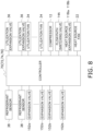
- FIG. 8 is a control block diagram of the air conditioner 100A according to the present embodiment.
- the controller 70 is electrically connected to the utilization expansion valve 36, the utilization fan 34, and the refrigerant sensor 38 of each of the plurality of utilization units 30, the compressor 12, the flow path switching valve 14A, the heat source expansion valves 118a and 118b, and the heat source fan 22 of the heat source unit 10, and the expansion valves 152a and 152b of each of the plurality of intermediate units 150.
- the controller 70 is also electrically connected to various sensors that measure a temperature and pressure of the refrigerant, a temperature of air in the air conditioned space, an outside air temperature, and the like.
- the controller 70 controls operations of various devices included in the air conditioner 100A on the basis of a control signal received by the utilization unit 30 from an operation remote controller (not shown), measurement signals of various sensors, and the like.
- the expansion valve 152a is fully opened, and the expansion valve 152b has a minimum opening degree.
- the opening degrees of the utilization expansion valves 36 of the utilization units 30A and 30B are appropriately adjusted, and the first heat source expansion valve 118a and the second heat source expansion valve 118b are fully opened.
- the flow of the refrigerant in the refrigerant circuit 190 will be described.
- the refrigerant is sucked into the compressor 12 via the suction pipe and compressed.
- the compressed high-pressure gas refrigerant flows into the heat source heat exchanger 116 via the discharge pipe, the first flow path switching valve 14a, the third flow path switching valve 14c, and the like, and condenses.
- the refrigerant having passed through the heat source heat exchanger 116 passes through the liquid-side shutoff valve 119c and flows into the liquid connection pipe 102a.
- the refrigerant having passed through the liquid connection pipe 102a reaches the first connecting pipe 102d and flows into the utilization units 30A and 30B.
- the refrigerant having reached the utilization unit 30A or 30B flows into the utilization expansion valve 36 and is decompressed.
- the decompressed refrigerant flows into each utilization heat exchanger 32 and evaporates.
- the refrigerant having passed through each utilization heat exchanger 32 flows, via the connection pipe 104b, into the pipes in which the expansion valves 152a of the intermediate units 150A and 150B are disposed, and reaches the second connecting pipe 102e.
- the refrigerant having reached the second connecting pipe 102e flows into the heat source unit 110 via the suction gas connection pipe 102b and is again sucked into the compressor 12.
- the expansion valve 152a has the minimum opening degree, and the expansion valve 152b is fully opened.
- the utilization expansion valves 36 of the utilization units 30A and 30B are fully opened, and the opening degrees of the first heat source expansion valve 118a and the second heat source expansion valve 118b are appropriately adjusted.
- the flow of the refrigerant in the refrigerant circuit 190 will be described.
- the refrigerant is sucked into the compressor 12 via an intake pipe and compressed.
- the compressed high-pressure gas refrigerant flows into the high-low pressure gas connection pipe 102c via the discharge pipe, the second flow path switching valve 14b, and the like.
- the refrigerant having passed through the high-low pressure gas connection pipe 102c reaches the third connecting pipe 102f.
- the refrigerant having reached the third connecting pipe 102f flows into the pipe of the intermediate unit 150A or 150B in which the expansion valve 152b is disposed, passes through the connection pipe 104b, and reaches the utilization unit 30A or 30b.
- the refrigerant having reached the utilization unit 30A or 30B flows into each utilization heat exchanger 32 and condenses.
- the refrigerant having passed through each utilization heat exchangers 32 flows into the first connecting pipe 102d.
- the refrigerant having reached the first connecting pipe 102d reaches the heat source unit 110 via the liquid connection pipe 102a.
- the refrigerant having reached the heat source unit 110 passes through the first heat source expansion valve 118a or the second heat source expansion valve 118b, and is decompressed in accordance with the opening degree.
- the decompressed refrigerant flows into the heat source heat exchanger 116 and evaporates.
- the refrigerant having passed through the heat source heat exchanger 116 is again sucked into the compressor 12 via the first flow path switching valve 14a or the third flow path switching valve 14c.
- the expansion valve 152a is fully opened, and the expansion valve 152b has the minimum opening degree.
- the opening degree of the utilization expansion valve 36 of the utilization unit 30A is appropriately adjusted.
- the expansion valve 152a has the minimum opening degree, and the expansion valve 152b is fully opened.
- the opening degree of the utilization expansion valve 36 of the utilization unit 30B is fully opened.
- the opening degrees of the first heat source expansion valve 118a and the second heat source expansion valve 118b are appropriately adjusted.
- the flow of the refrigerant in the refrigerant circuit 190 will be described.
- the compressor 12 When the compressor 12 is operated, the refrigerant is sucked into the compressor 12 via the intake pipe and compressed.
- the high-pressure gas refrigerant compressed by the compressor 12 flows into the high-low pressure gas connection pipe 102c via the discharge pipe, the second flow path switching valve 14b, and the like.
- the refrigerant having passed through the high-low pressure gas connection pipe 102c reaches the third connecting pipe 102f.
- the refrigerant having passed through the third connecting pipe 102f flows into the intermediate unit 150B, flows through the pipe in which the expansion valve 152b is disposed, and flows into the connection pipe 104b.
- the refrigerant having passed through the connection pipe 104b reaches the utilization unit 30B, flows into the utilization heat exchanger 32, and condenses.
- the condensed refrigerant flows into the first connecting pipe 102d linked to the utilization unit 30A through the first connecting pipe 102d, and reaches the utilization unit 30A.
- the refrigerant having reached the utilization unit 30A flows into the utilization expansion valve 36 and is decompressed in accordance with the opening degree.
- the decompressed refrigerant flows into the utilization heat exchanger 32 and evaporates.
- the evaporated refrigerant reaches the intermediate unit 150A via the connection pipe 104b, flows into the pipe in which the expansion valve 152a is disposed, and reaches the second connecting pipe 102e.
- the refrigerant having reached the second connecting pipe 102e flows into the heat source unit 110 via the suction gas connection pipe 102b and is again sucked into the compressor 12.
- the controller 70 When the refrigerant sensor 38 of any of the utilization units 30 detects a refrigerant leakage, the controller 70 fully closes the utilization expansion valve 36 of the utilization unit 30 in which the refrigerant leakage is detected and the expansion valves (shutoff valves) 152a and 152b of the intermediate unit 150 corresponding to the utilization unit 30 in which the refrigerant leakage is detected to shut off the inflow of the refrigerant from the heat source unit 110 to the utilization unit 30.
- the controller 70 When a refrigerant leakage is detected in any of the utilization units 30, the controller 70 does not stop the operation of the compressor 12 but continues the cooling operation or the heating operation in the utilization unit 30 in which the refrigerant leakage is not detected. However, when a refrigerant leakage is detected in any of the utilization units 30, the controller 70 may stop the operation of the compressor 12 and stop the cooling operation or the heating operation in the unit other than the utilization unit 30 in which the refrigerant leakage is detected.
- the remote controller for operation is notified of the utilization unit 30 from which the refrigerant leakage is detected.
- the operator recovers the refrigerant in the pipe and the utilization heat exchanger 32 disposed between the utilization expansion valve 36 and the expansion valves 152a and 152b from the service port 60 corresponding to the utilization unit 30 in which the refrigerant leakage has been detected.
- the air conditioner 100A includes the heat source unit 110, the utilization unit 30, the connection pipe, the expansion valves 152a and 152b as an example of a shutoff valve, and the service port 60.
- the utilization unit 30 is disposed in the air conditioned space.
- the connection pipe connects the heat source unit 110 and the utilization unit 30.
- the expansion valves 152a and 152b are disposed outside the air conditioned space and are provided in the connection pipe (gas-side connection pipe).
- the service port 60 is provided between the expansion valves 152a and 152b and the utilization unit 30 in the connection pipe.
- the service port 60 is provided closer to the utilization unit 30 than the expansion valves 152a and 152b that shut off the flow of the refrigerant to the utilization unit 30. Therefore, in the air conditioner 100A, when a refrigerant leaks, the refrigerant can be quickly recovered from the utilization unit 30 in which the refrigerant leaks.
- the refrigerant sensor 38 detects a so-called slow leak
- the connection pipe gas-side connection pipe
- the expansion valves 152a and 152b and the utilization unit 30 there is a possibility that a large amount of refrigerant remains in the connection pipe (gas-side connection pipe) between the expansion valves 152a and 152b and the utilization unit 30, and thus, the residual refrigerant can be quickly recovered from the service port 60.
- the air conditioner 100A includes the intermediate unit 150 as an example of a shutoff valve unit including the expansion valves 152a and 152b and the casing 154 accommodating the expansion valves 152a and 152b.
- the service port 60 is provided in the intermediate unit 150.
- the service port 60 can also be attached to the connection pipe 4 when the intermediate unit 150 is attached to the connection pipe 4, the efficiency of an installation work can be improved.
- the service port 60 (60a) is disposed outside the casing 154.
- the workability of the refrigerant recovery work is enhanced (the cover or the like covering the expansion valves 152a and 152b of the casing 154 is not required to be removed).
- the service port 60 When the service port 60 is disposed outside the casing 154, the service port 60 is preferably disposed in the side part of the casing 154.
- the reason is similar to the reason for arranging the service port 60 in the side part of the casing 54 in the first embodiment.
- the service port 60 (60b) is disposed in the casing 154.
- the service port 60 since the service port 60 is disposed in the casing 154 which is not in direct contact with the outside air, the occurrence of dew condensation around the service port 60 can be prevented.
- the length of the connection pipe between the expansion valves 152a and 152b and the utilization unit 30 is less than or equal to 40 m.
- the length of the connection pipe between the expansion valves 152a and 152b and the utilization unit 30 is relatively short (since the amount of the refrigerant in the connection pipe between the expansion valves 152a and 152b and the utilization unit 30 is relatively small), even if the refrigerant leaks from the refrigerant leakage spot of the utilization unit 30 before a completion of refrigerant recovery, the refrigerant concentration in the air conditioned space is less likely to increase.
- the length of the connection pipe between the expansion valves 152a and 152b and the utilization unit 30 is preferably less than or equal to 2 m.
- the utilization unit 30 is ceiling-embedded.
- the service port 60 is provided in the ceiling space and near the inspection port OP of the utilization unit 30 provided on the ceiling.
- the shutoff valve is provided near the inspection port OP for the utilization unit 30, when the refrigerant leaks from the utilization unit 30, the refrigerant can be quickly recovered from the utilization unit 30 in which the refrigerant leaks.
- the service port 60 may be installed at a position accessible from a location other than the air conditioned space.
- the refrigerant leaks from the utilization unit 30, there is a possibility that the refrigerant flows into the air conditioned space to be air-conditioned by the utilization unit 30.
- the service port 60 accessible from outside of the air conditioned space, the operator can recover the refrigerant without entering the air conditioned space in which the refrigerant can possibly exist, and the safety is higher.
- the air conditioner 100A includes the plurality of utilization units 30.
- Each of the utilization units 30 is provided with the expansion valves 152a and 152b for a dedicated use and the service port 60 for a dedicated use.
- the air conditioner 100A When the refrigerant leaks from one of the plurality of utilization units 30, the air conditioner 100Arecovers the refrigerant in the utilization unit 30 in which the refrigerant leaks, and can continue the operation of the other utilization units 30.
- the expansion valves 152a and 152b as an example of the shutoff valve are flow rate control valves whose opening degree is adjustable.
- the expansion valves 152a and 152b also function as flow rate control valves, the number of components can be reduced.
- the expansion valves 152a and 152b are provided in the gas-side connection pipe.
- the refrigerant remaining between the utilization expansion valve 36 and the expansion valves 152a and 152b of the utilization unit 30 that are fully closed when a refrigerant leakage is detected can be recovered from the service port 60.
- Modifications 1A and 1B in the first embodiment are also applicable to the second embodiment.
- the intermediate unit 150 in which the two expansion valves 152a and 152b are disposed on a gas side has been described as an example.
- the intermediate unit may have the two expansion valves 152a and 152b on the gas side and one valve on a liquid side.
- the intermediate unit may be a unit having a total of three expansion valves, including an expansion valve disposed in the first connecting pipe 102d in addition to the two expansion valves 152a and 152b.
- the expansion valve disposed in the first connecting pipe 102d of the intermediate unit may function as a shutoff valve that is closed when the refrigerant leaks.
- the air conditioner 100 includes the shutoff valve unit 50 having the shutoff valve 52 and the casing 54 accommodating the shutoff valve 52
- the air conditioner 100A according to the second embodiment includes the intermediate unit 150 having the expansion valves 152a and 152b and the casing 154 accommodating the expansion valves 152a and 152b.
- the shutoff valve 52 and the expansion valves 152a and 152b may be directly attached to the connection pipe.
- Patent Literature 1 JP 2023-50282 A
Landscapes
- Engineering & Computer Science (AREA)
- Mechanical Engineering (AREA)
- General Engineering & Computer Science (AREA)
- Physics & Mathematics (AREA)
- Thermal Sciences (AREA)
- Chemical & Material Sciences (AREA)
- Combustion & Propulsion (AREA)
- Air Conditioning Control Device (AREA)
Abstract
Description
- The present disclosure relates to an air conditioner.
- Conventionally, as disclosed in Patent Literature 1 (
JP 2023-50282 A - In such a refrigeration cycle apparatus, when a refrigerant leakage is detected in a utilization unit, there is a possibility that it takes a long time to complete recovery of the refrigerant from the utilization unit in which the refrigerant leaks.
- An air conditioner according to a first aspect includes a heat source unit, a utilization unit, a connection pipe, a shutoff valve, and a service port. The utilization unit is disposed in an air conditioned space. The connection pipe connects the heat source unit and the utilization unit. The shutoff valve is disposed outside the air conditioned space and is provided in the connection pipe. The service port is provided between the shutoff valve and the utilization unit in the connection pipe.
- In the air conditioner according to the first aspect, the service port is provided closer to the utilization unit than the shutoff valve that shuts off a flow of a refrigerant to the utilization unit. Therefore, in the air conditioner according to the first aspect, when the refrigerant leaks, the refrigerant can be quickly recovered from the utilization unit in which the refrigerant leaks.
- An air conditioner according to a second aspect is the air conditioner according to the first aspect, and includes a shutoff valve unit including the shutoff valve and a casing that accommodates the shutoff valve. The service port is provided in the shutoff valve unit. The service port is disposed outside the casing.
- In the air conditioner according to the second aspect, the service port is provided in the shutoff valve unit. Therefore, since the service port can also be provided in the connection pipe when the shutoff valve unit is attached to the connection pipe, the efficiency of an installation work can be improved. In the air conditioner, since the service port is disposed outside the casing, workability of a refrigerant recovery work is enhanced.
- An air conditioner according to a third aspect is the air conditioner according to the second aspect, in which the service port is disposed in a side part of the casing.
- As arrangement of the service port outside the casing, it is also conceivable to provide the service port in a lower part and an upper part of the casing. However, when the service port is provided in the lower part of the casing, there is a possibility that a portion of the service port becomes an oil reservoir. In addition, when the service port is provided in the upper part of the casing and the casing accommodating the shutoff valve is disposed in an attic place or the like, there is a possibility that it is not easy to perform the refrigerant recovery work.
- However, in the air conditioner according to the third aspect, since the service port is provided in the side part of the casing, it is possible to obtain good workability of refrigerant recovery while suppressing the problem of oil reservoir.
- An air conditioner according to a fourth aspect is the air conditioner according to the first aspect, and includes a shutoff valve unit including the shutoff valve and a casing that accommodates the shutoff valve. The service port is provided in the shutoff valve unit. The service port is disposed in the casing.
- In the air conditioner according to the fourth aspect, since the service port is provided in the casing, the occurrence of dew condensation around the service port can be prevented.
- An air conditioner according to a fifth aspect is the air conditioner according to any one of the first to fourth aspects, in which the shutoff valve is a flow rate control valve whose opening degree is adjustable.
- In the air conditioner according to the fifth aspect, since the shutoff valve also functions as a flow rate control valve, the number of components can be reduced.
- An air conditioner according to a sixth aspect is the air conditioner according to any of the first to fifth aspects, in which the shutoff valve is provided in a gas connection pipe connecting the heat source unit and the utilization unit.
- In the air conditioner according to the sixth aspect, the refrigerant remaining between the utilization expansion valve and the shutoff valve of the utilization unit that are fully closed when a refrigerant leakage is detected can be recovered from the service port.
- An air conditioner according to a seventh aspect is the air conditioner according to any of the first to sixth aspects, in which a length of the connection pipe between the shutoff valve and the utilization unit is less than or equal to 2 m.
- In the air conditioner according to the seventh aspect, since the shutoff valve is disposed near the utilization unit, when the refrigerant leaks, the refrigerant can be quickly recovered from the utilization unit in which the refrigerant leaks.
- An air conditioner according to an eighth aspect is the air conditioner according to any of the first to seventh aspects, in which the utilization unit is ceiling-embedded. The service port is disposed in an ceiling space and near an inspection port of the utilization unit provided on the ceiling.
- In the air conditioner according to the eighth aspect, since the shutoff valve is provided near the inspection port for the utilization unit, when the refrigerant leaks from the utilization unit, the refrigerant can be quickly recovered from the utilization unit in which the refrigerant leaks.
- An air conditioner according to a ninth aspect is the air conditioner according to any of the first to sixth aspects, in which a length of the connection pipe between the shutoff valve and the utilization unit is less than or equal to 40 m.
- In the air conditioner according to the ninth aspect, since the length of the connection pipe between the shutoff valve and the utilization unit is less than or equal to 40 m, even if the refrigerant leaks from a refrigerant leakage spot of the utilization unit before a completion of refrigerant recovery, the refrigerant concentration in the air conditioned space is less likely to increase.
- An air conditioner according to a tenth aspect is the air conditioner according to any of the first to ninth aspects, in which the service port is installed at a position accessible from a location other than the air conditioned space.
- When the refrigerant leaks from the utilization unit, there is a possibility that the refrigerant flows into the air conditioned space to be air-conditioned by the utilization unit. In the air conditioner according to the tenth aspect, since the service port is accessible from outside of the air conditioned space, an operator can recover the refrigerant without entering the air conditioned space in which the refrigerant can possibly exist, and the safety is higher.
- An air conditioner according to an eleventh aspect is the air conditioner according to any of the first to tenth aspects, and includes a plurality of the utilization units. Each of the utilization units is provided with the shutoff valve for a dedicated use and the service port for a dedicated use.
- In the air conditioner according to the eleventh aspect, when the refrigerant leaks from one of the plurality of utilization units, the air conditioner recovers the refrigerant in the utilization unit in which the refrigerant leaks, and can continue the operation of the other utilization units.
-
- [
FIG.1] FIG. 1 is a schematic configuration diagram of an air conditioner according to a first embodiment. - [
FIG. 2] FIG. 2 is a control block diagram of the air conditioner inFIG. 1 . - [
FIG. 3] FIG. 3 is a schematic perspective view of a shutoff valve unit of the air conditioner inFIG. 1 . - [
FIG.4] FIG. 4 is a diagram showing an example of arrangement of the shutoff valve unit of the air conditioner inFIG. 1 . - [
FIG.5] FIG. 5 is a diagram showing another example of the arrangement of the shutoff valve unit of the air conditioner inFIG. 1 . - [
FIG.6] FIG. 6 is a refrigerant circuit diagram in a heat source unit of an air conditioner according to a second embodiment. - [
FIG.7] FIG. 7 is a refrigerant circuit diagram of a portion other than the heat source unit of the air conditioner according to the second embodiment. - [
FIG.8] FIG. 8 is a control block diagram of the air conditioner according to the second embodiment. - [
FIG.9] FIG. 9 is a schematic perspective view of a shutoff valve unit of the air conditioner according to the second embodiment. - Embodiment of an air conditioner will be described with reference to the drawings.
- An
air conditioner 100 according to a first embodiment will be described with reference to a schematic configuration diagram ofFIG. 1 . - The
air conditioner 100 is an apparatus that performs air conditioning of a plurality of air conditioned spaces in a building. Theair conditioner 100 mainly includes aheat source unit 10, a plurality ofutilization units 30, ashutoff valve unit 50 and aservice port 60 provided for each of the plurality ofutilization units 30, and a controller 70 (seeFIG. 1 ). The number ofutilization units 30 illustrated inFIG. 1 does not limit the number ofutilization units 30 included in theair conditioner 100. Unlike the present embodiment, theair conditioner 100 may be, for example, an apparatus that includes only oneutilization unit 30 and performs air conditioning in a single air conditioned space. - As shown in
FIG. 1 , theheat source unit 10 and theutilization units 30 are connected byconnection pipes 2 and 4. Theheat source unit 10 and theutilization units 30 are connected by theconnection pipes 2 and 4 to form arefrigerant circuit 90 including acompressor 12, a heatsource heat exchanger 16, a heatsource expansion valve 18, autilization expansion valve 36, autilization heat exchanger 32, and the like, which will be described later. As shown inFIG. 1 , theshutoff valve unit 50 is provided in theconnection pipe 4. Theconnection pipe 4 is a gas connection pipe through which a refrigerant flows from theutilization units 30 to theheat source unit 10 during a cooling operation and flows from theheat source unit 10 to theutilization units 30 during a heating operation. Theservice port 60 for recovering the refrigerant is provided in theconnection pipe 4 between ashutoff valve 52 of theshutoff valve unit 50 and theutilization units 30. The controller 70 controls an operation of various parts of theair conditioner 100. - The
utilization unit 30 is installed in the air conditioned space to be air-conditioned. Theutilization unit 30 is a ceiling-embedded unit, a ceiling pendant unit, a wall-mounted unit, a floor-standing unit, or the like. In the present embodiment, a case where theutilization unit 30 is ceiling-embedded will be described as an example. - The
utilization unit 30 mainly includes autilization heat exchanger 32, autilization fan 34, autilization expansion valve 36, autilization control unit 72, arefrigerant sensor 38, and acasing 31 that accommodates these units. - The
utilization heat exchanger 32 causes heat exchange between the refrigerant flowing inside theutilization heat exchanger 32 and air in the air conditioned space. Theutilization heat exchanger 32 is, for example, a fin-and-tube heat exchanger including a plurality of heat transfer fins and a plurality of heat transfer tubes. - The
utilization fan 34 supplies the air taken in from the air conditioned space to theutilization heat exchanger 32. Examples of theutilization fan 34 include a centrifugal fan such as a turbo fan and a sirocco fan. Theutilization fan 34 is driven by a motor (not shown). - The
utilization expansion valve 36 is provided in a pipe connecting the connection pipe 2 and a liquid-side end of theutilization heat exchanger 32, and is a mechanism for adjusting a pressure and flow rate of the refrigerant. Theutilization expansion valve 36 is an electric valve (electronic expansion valve) whose opening degree is adjustable. Theutilization expansion valve 36 is also used as a shutoff valve at a time of refrigerant leakage, and has a small leakage amount while the valve is closed. For example, theutilization expansion valve 36 is a valve having a leakage amount of 300cm3/min(air, ΔP=1.0 MPa) or less while the valve is closed. - The
refrigerant sensor 38 is a sensor that detects a leakage of the refrigerant. Therefrigerant sensor 38 is provided, for example, near theutilization heat exchanger 32. - The
utilization control unit 72 includes an arithmetic and control device and a storage device. Examples of the arithmetic and control device include a processor such as a CPU and a GPU. Examples of the storage device include a storage medium such as a RAM, a ROM, and a flash memory. The arithmetic and control device reads a program stored in the storage device and performs predetermined calculation processing in accordance with the program, and thus, controls operations of various devices of theair conditioner 100 as the controller 70 in cooperation with a heatsource control unit 74 of theheat source unit 10 and avalve control unit 76 of theshutoff valve unit 50. The function of the controller 70 will be described later. - The
heat source unit 10 is installed on a rooftop of the building where theair conditioner 100 is installed, a machine chamber, or the like. As shown inFIG. 1 , theheat source unit 10 mainly includes thecompressor 12, a flowpath switching valve 14, the heatsource heat exchanger 16, the heatsource expansion valve 18, anaccumulator 20, aheat source fan 22, aliquid shutoff valve 24, agas shutoff valve 26, and the heatsource control unit 74. Theheat source unit 10 also includes asuction pipe 28a, adischarge pipe 28b,gas refrigerant pipes refrigerant pipe 28d. - The
suction pipe 28a connects the flowpath switching valve 14 and a suction side of thecompressor 12. Thesuction pipe 28a is provided with theaccumulator 20. Thedischarge pipe 28b connects a discharge side of thecompressor 12 and the flowpath switching valve 14. Thegas refrigerant pipe 28c connects the flowpath switching valve 14 and a gas side end of the heatsource heat exchanger 16. The liquidrefrigerant pipe 28d connects a liquid-side end of the heatsource heat exchanger 16 and the connection pipe 2. The liquidrefrigerant pipe 28d is provided with the heatsource expansion valve 18. A connecting portion of the liquidrefrigerant pipe 28d and the connection pipe 2 is provided with theliquid shutoff valve 24. Thegas refrigerant pipe 28e connects the flowpath switching valve 14 and theconnection pipe 4. A connecting portion of thegas refrigerant pipe 28e and theconnection pipe 4 is provided with thegas shutoff valve 26. Theliquid shutoff valve 24 and thegas shutoff valve 26 are openable and closable manually. - The
compressor 12 sucks a low-pressure refrigerant in a refrigeration cycle from thesuction pipe 28a, compresses the refrigerant by a compression mechanism (not shown), and discharges the compressed high-pressure refrigerant in the refrigeration cycle to thedischarge pipe 28b. Thecompressor 12 is a displacement compressor of a rotary type or a scroll type. The compression mechanism of thecompressor 12 is driven by a motor (not shown). The number of rotations of the motor of thecompressor 12 is controllable by an inverter. - The flow
path switching valve 14 is a mechanism that switches a refrigerant flow path between a first state and a second state. In the first state, the flowpath switching valve 14 causes thesuction pipe 28a to communicate with thegas refrigerant pipe 28e and causes thedischarge pipe 28b to communicate with thegas refrigerant pipe 28c as indicated by a solid line in the flowpath switching valve 14 inFIG. 1 . In the second state, the flowpath switching valve 14 causes thesuction pipe 28a to communicate with thegas refrigerant pipe 28c and causes thedischarge pipe 28b to communicate with thegas refrigerant pipe 28e as indicated by a broken line in the flowpath switching valve 14 inFIG. 1 . The flowpath switching valve 14 is, for example, a four-way switching valve. - During the cooling operation, the flow
path switching valve 14 brings the refrigerant flow path into the first state. At this time, the refrigerant discharged from thecompressor 12 flows through therefrigerant circuit 90 in the order of the heatsource heat exchanger 16, the heatsource expansion valve 18, theutilization expansion valve 36, and theutilization heat exchanger 32, and returns to thecompressor 12. In the first state, the heatsource heat exchanger 16 functions as a condenser, and theutilization heat exchanger 32 functions as an evaporator. - During the heating operation, the flow
path switching valve 14 brings the refrigerant flow path into the second state. At this time, the refrigerant discharged from thecompressor 12 flows through therefrigerant circuit 90 in the order of theutilization heat exchanger 32, theutilization expansion valve 36, the heatsource expansion valve 18, and the heatsource heat exchanger 16, and returns to thecompressor 12. In the second state, the heatsource heat exchanger 16 functions as an evaporator, and theutilization heat exchanger 32 functions as a condenser. - The heat
source heat exchanger 16 causes heat exchange between the refrigerant flowing inside the heatsource heat exchanger 16 and air around theheat source unit 10. The heatsource heat exchanger 16 is, for example, a fin-and-tube heat exchanger including a plurality of heat transfer fins and a plurality of heat transfer tubes. - The heat
source expansion valve 18 is a mechanism configured to control pressure and a flow rate of the refrigerant flowing in the liquidrefrigerant pipe 28d. As shown inFIG. 1 , the heatsource expansion valve 18 is provided in the liquidrefrigerant pipe 28d. The heatsource expansion valve 18 is an electric valve (electronic expansion valve) whose opening degree is adjustable. - The
accumulator 20 is a container provided in thesuction pipe 28a and having a gas-liquid separation function of separating an inflowing refrigerant into a gas refrigerant and a liquid refrigerant. A refrigerant flowing into theaccumulator 20 is separated into a gas refrigerant and a liquid refrigerant, and the gas refrigerant collecting in an upper space flows into thecompressor 12. - The
heat source fan 22 supplies the air around theheat source unit 10 to the heatsource heat exchanger 16. Theheat source fan 22 is, for example, an axial fan such as a propeller fan. Theheat source fan 22 is driven by a motor (not shown). - The heat
source control unit 74 includes a arithmetic and control device and a storage device. Examples of the arithmetic and control device include a processor such as a CPU and a GPU. Examples of the storage device include a storage medium such as a RAM, a ROM, and a flash memory. The arithmetic and control device reads a program stored in the storage device and performs predetermined calculation processing in accordance with the program, and thus, controls operations of various devices of theair conditioner 100 as the controller 70 in cooperation with theutilization control unit 72 of theutilization unit 30 and thevalve control unit 76 of theshutoff valve unit 50. The function of the controller 70 will be described later. - The
shutoff valve unit 50 is disposed in the connection pipe 4 (gas connection pipe). Oneshutoff valve unit 50 is provided corresponding to eachutilization unit 30. Theshutoff valve unit 50 is a unit that shuts off a flow of the refrigerant at a time of refrigerant leakage in thecorresponding utilization unit 30 and the like. - The
shutoff valve unit 50 is disposed outside the air conditioned space. For example, theshutoff valve unit 50 is disposed in an ceiling space of the air conditioned space (seeFIG. 4 ) or in a space under a floor of the air conditioned space. Theshutoff valve unit 50 is disposed in an ceiling space of a corridor adjacent to the air conditioned space (seeFIG. 5 ). The installation location of theshutoff valve unit 50 is not limited to the exemplified location, and the shut offvalve unit 50 may be disposed at another location outside the air conditioned space. - The
shutoff valve unit 50 mainly includes theshutoff valve 52, acasing 54, and thevalve control unit 76. - The
shutoff valve 52 is a valve having a small leakage amount while the valve is closed. For example, theshutoff valve 52 is an electromagnetic valve having a leakage amount of 300cm3/min(air, ΔP=1.0 MPa) or less while the valve is closed. However, the type of the valve is not limited to the electromagnetic valve, and may be, for example, an electric valve or the like whose opening degree is adjustable. - The length of the connection pipe between the
shutoff valve 52 and the utilization unit 30 (a total of the length of a pipe closer to theutilization unit 30 than theshutoff valve 52 in theshutoff valve unit 50 and the length of theconnection pipe 4 connecting theshutoff valve unit 50 and the utilization unit 30) is preferably less than or equal to 40 m. In such a configuration, even if the refrigerant leaks from a refrigerant leakage spot of the utilization unit before a refrigerant recovery from theservice port 60 provided between theshutoff valve 52 and theutilization unit 30 is completed, a refrigerant concentration in the air conditioned space is less likely to increase since the pipe length included in a refrigerant recovery portion is relatively short and the amount of the refrigerant in the pipe is relatively small. - The length of the connection pipe between the
shutoff valve 52 and theutilization unit 30 is preferably less than or equal to 2 m. Such a configuration allows a prompt recovery of the refrigerant from theutilization unit 30 in which the refrigerant leaks by using theservice port 60 provided between theshutoff valve 52 and theutilization unit 30. - The
casing 54 is a housing that accommodates theshutoff valve 52 inside. A condensation-proof material is disposed inside thecasing 54 to suppresses dew condensation around theshutoff valve 52. - The
valve control unit 76 includes a arithmetic and control device and a storage device. Examples of the arithmetic and control device include a processor such as a CPU and a GPU. Examples of the storage device include a storage medium such as a RAM, a ROM, and a flash memory. The arithmetic and control device reads a program stored in the storage device and performs predetermined calculation processing in accordance with the program, and thus, controls operations of various devices of theair conditioner 100 as the controller 70 in cooperation with theutilization control unit 72 of theutilization unit 30 and the heatsource control unit 74 of theheat source unit 10. The function of the controller 70 will be described later. - The
service port 60 is a component for recovering the refrigerant filled in theair conditioner 100, and a refrigerant recovery container is connected to theservice port 60 via a connection component or a hose at the time of recovering the refrigerant, and the refrigerant is recovered in the refrigerant recovery container. - The
service port 60 is provided in theconnection pipe 4 between theshutoff valve 52 of theshutoff valve unit 50 and theutilization unit 30. Theservice port 60 may be provided in theconnection pipe 4 independently of theshutoff valve unit 50. - However, the
service port 60 is preferably provided in the shutoff valve unit 50 (a pipe constituting a part of theshutoff valve unit 50 and disposed closer to theutilization unit 30 than the shutoff valve 52). When theservice port 60 is provided independently of theshutoff valve unit 50, work of attaching theservice port 60 and theshutoff valve unit 50 to theconnection pipe 4 is required. On the other hand, if theservice port 60 is incorporated in theshutoff valve unit 50 in advance, the on-site work can be reduced. - If the
service port 60 is disposed outside thecasing 54 of theshutoff valve unit 50 as indicated by a solid line inFIG. 3 , the operator can start a refrigerant recovery work without removing a cover or the like covering theshutoff valve 52 of theshutoff valve unit 50, and thus workability is improved. - In this manner, when the
service port 60 is disposed outside thecasing 54, theservice port 60 is particularly preferably disposed in a side part of thecasing 54. In other words, theservice port 60 is particularly preferably provided at a position accessible by the operator from the side part of thecasing 54. - For example, the
service port 60 may be disposed in an upper part of thecasing 54 and provided at a position accessible by the operator from the upper part of thecasing 54. However, in this case, there is a possibility that theshutoff valve unit 50 is difficult for an operator to access when theshutoff valve unit 50 is installed in the ceiling space,. Alternatively, theservice port 60 may be disposed in a lower part of thecasing 54. However, in this case, if theshutoff valve unit 50 is installed in the ceiling space, there is a possibility that an oil is accumulated at theservice port 60. - However, by arranging the
service port 60 in the side part of thecasing 54, it is possible to obtain good workability of refrigerant recovery while preventing the problem of oil accumulation in theservice port 60. - If the
service port 60 is disposed inside thecasing 54 of theshutoff valve unit 50 as indicated by a broken line inFIG. 3 , although it is necessary to remove the cover covering theshutoff valve 52 and the like, theservice port 60 is not exposed to a surrounding environment, and thus, the occurrence of dew condensation in theservice port 60 can be prevented. - In a case where the
utilization unit 30 is ceiling-embedded, the service port 60 (in a case where theservice port 60 is provided in theshutoff valve unit 50, the shutoff valve unit 50) is provided in the ceiling space and near an inspection port OP of theutilization unit 30 provided on the ceiling. Near the inspection port OP of theutilization unit 30 means a distance (for example, 50 cm) within which theservice port 60 can be reached from the inspection port OP. In a case where theservice port 60 is provided separately from theshutoff valve unit 50, at least theservice port 60 is preferably provided in the ceiling space and near the inspection port OP of theutilization unit 30 provided on the ceiling. In such a configuration, when the refrigerant leaks from theutilization unit 30, the refrigerant can be quickly recovered from theutilization unit 30 in which the refrigerant leaks. - From the viewpoint of safety of the operator, the
service port 60 is preferably disposed at a position accessible from a location other than the air conditioned space. For example, the service port 60 (theshutoff valve unit 50 particularly in a case where theshutoff valve unit 50 is provided with the service port 60) is provided in the ceiling space of the corridor adjacent to the air conditioned space and near the inspection port OP provided on the ceiling. Near the inspection port OP means a distance (for example, 50 cm) within which theservice port 60 can be reached from the inspection port OP. When the refrigerant leaks from theutilization unit 30, there is a possibility that the refrigerant flows into the air conditioned space. However, by arranging theservice port 60 at a position accessible to a location other than the air conditioned space, the operator can recover the refrigerant without entering the air conditioned space where the refrigerant can possibly exist. - The controller 70 includes the
utilization control unit 72, the heatsource control unit 74, and thevalve control unit 76. The controller 70 controls an overall operation of theair conditioner 100 by causing each arithmetic and control device of theutilization control unit 72, the heatsource control unit 74, and thevalve control unit 76 to execute the program stored in each storage device. -
FIG. 2 is a control block diagram of theair conditioner 100 according to the present embodiment. - As shown in
FIG. 2 , the controller 70 is electrically connected to theutilization expansion valve 36, theutilization fan 34, and therefrigerant sensor 38 of each of the plurality ofutilization units 30, thecompressor 12, the flowpath switching valve 14, the heatsource expansion valve 18, and theheat source fan 22 of theheat source unit 10, and theshutoff valve 52 of each of the plurality ofshutoff valve units 50. The controller 70 is also electrically connected to various sensors that measure a temperature and pressure of the refrigerant, a temperature of air in the air conditioned space, an outside air temperature, and the like. The controller 70 controls operations of various devices included in theair conditioner 100 on the basis of a control signal received by theutilization unit 30 from an operation remote controller (not shown), measurement signals of various sensors, and the like. - The controller 70 mainly performs the cooling operation and the heating operation. The controller 70 also has a refrigerant leakage prevention function.
- Upon receiving an instruction to perform the cooling operation from the operation remote controller via the
utilization unit 30, for example, the controller 70 brings the flowpath switching valve 14 into the first state and starts the operation of thecompressor 12. In addition, the number of rotations of the motor of thecompressor 12 and opening degrees of the heatsource expansion valve 18 and theutilization expansion valve 36 are appropriately controlled on the basis of a measurement result of a sensor that is provided in therefrigerant circuit 90 and measures the temperature and pressure of the refrigerant. Note that during the cooling operation, theshutoff valve 52 is controlled to be fully open. - The flow of the refrigerant in the
refrigerant circuit 90 will be described. When the operation of thecompressor 12 is started, a gas refrigerant having a low pressure in the refrigeration cycle (hereinafter simply referred to as low pressure) is sucked into thecompressor 12 and compressed by the compression mechanism of thecompressor 12 to become a gas refrigerant having a high pressure in the refrigeration cycle (hereinafter simply referred to as high pressure). The high-pressure gas refrigerant is sent to the heatsource heat exchanger 16 via the flowpath switching valve 14, exchanges heat with the air around theheat source unit 10 supplied by theheat source fan 22 to be condensed, and becomes a high-pressure liquid refrigerant. The high-pressure liquid refrigerant flows through the liquidrefrigerant pipe 28d and passes through the heatsource expansion valve 18. The high-pressure liquid refrigerant sent to theutilization unit 30 is decompressed to a pressure close to a suction pressure of thecompressor 12 in theutilization expansion valve 36, becomes a refrigerant in a gas-liquid two-phase state, and is sent to theutilization heat exchanger 32. The refrigerant in the gas-liquid two-phase state exchanges heat with air in the air conditioned space supplied to theutilization heat exchanger 32 by theutilization fan 34 in theutilization heat exchanger 32 and evaporates to become a low-pressure gas refrigerant. The low-pressure gas refrigerant is sent to theheat source unit 10 via theconnection pipe 4, and flows into theaccumulator 20 via the flowpath switching valve 14. The low-pressure gas refrigerant having flowed into theaccumulator 20 is sucked into thecompressor 12 again. The temperature of the air supplied to theutilization heat exchanger 32 is lowered by heat exchange with the refrigerant flowing through theutilization heat exchanger 32, and the cooled air is blown into the air conditioned space. - Upon receiving an instruction to perform the heating operation from the operation remote controller via the
utilization unit 30, for example, the controller 70 brings the flowpath switching valve 14 into the second state and starts the operation of thecompressor 12. In addition, the number of rotations of the motor of thecompressor 12 and opening degrees of the heatsource expansion valve 18 and theutilization expansion valve 36 are appropriately controlled on the basis of a measurement result of a sensor that is provided in therefrigerant circuit 90 and measures the temperature and pressure of the refrigerant. Note that during the heating operation, theshutoff valve 52 is controlled to be fully open. - The flow of the refrigerant in the
refrigerant circuit 90 will be described. When thecompressor 12 is activated, a low-pressure gas refrigerant is sucked into thecompressor 12 and is compressed by thecompressor 12 into a high-pressure gas refrigerant. The high-pressure gas refrigerant is sent to theutilization heat exchanger 32 via the flowpath switching valve 14, exchanges heat with the air in the air conditioned space supplied to theutilization heat exchanger 32 by theutilization fan 34, and is condensed into a high-pressure liquid refrigerant. The temperature of the air supplied to theutilization heat exchanger 32 is increased by heat exchange with the refrigerant flowing through theutilization heat exchanger 32, and the heated air is blown into the air conditioned space. The high-pressure liquid refrigerant having passed through theutilization heat exchanger 32 is decompressed in theutilization expansion valve 36. The decompressed liquid refrigerant is sent to theheat source unit 10 via the connection pipe 2 and flows into the liquidrefrigerant pipe 28d. The refrigerant flowing through the liquidrefrigerant pipe 28d is decompressed to near the suction pressure of thecompressor 12 in the heatsource expansion valve 18, becomes a refrigerant in a gas-liquid two-phase state, and flows into the heatsource heat exchanger 16. The low-pressure refrigerant in the gas-liquid two-phase state that has flowed into the heatsource heat exchanger 16 exchanges heat with the air around theheat source unit 10 supplied by theheat source fan 22 and evaporates to become a low-pressure gas refrigerant. The low-pressure gas refrigerant flows into theaccumulator 20 via the flowpath switching valve 14. The low-pressure gas refrigerant having flowed into theaccumulator 20 is sucked into thecompressor 12 again. - When the
refrigerant sensor 38 of any of theutilization units 30 detects a refrigerant leakage, the controller 70 fully closes theutilization expansion valve 36 of theutilization unit 30 in which the refrigerant leakage is detected and theshutoff valve 52 of theshutoff valve unit 50 corresponding to theutilization unit 30 in which the refrigerant leakage is detected to shut off the inflow of the refrigerant to theutilization unit 30 through theconnection pipes 2 and 4. - When a refrigerant leakage is detected in any of the
utilization units 30, the controller 70 does not stop the operation of thecompressor 12 but continues the cooling operation or the heating operation in theutilization unit 30 in which the refrigerant leakage is not detected. However, when a refrigerant leakage is detected in any of theutilization units 30, the controller 70 may stop the operation of thecompressor 12 and stop the cooling operation or the heating operation in the unit other than theutilization unit 30 in which the refrigerant leakage is detected. - When the
refrigerant sensor 38 of any of theutilization units 30 detects a refrigerant leakage, for example, the remote controller for operation is notified of theutilization unit 30 from which the refrigerant leakage is detected. On the basis of this notification, the operator recovers the refrigerant in the pipe and theutilization heat exchanger 32 disposed between theutilization expansion valve 36 and theshutoff valve 52 from theservice port 60 corresponding to theutilization unit 30 in which the refrigerant leakage has been detected. - (3-1)
Theair conditioner 100 includes theheat source unit 10, theutilization unit 30, theconnection pipes 2 and 4, theshutoff valve 52, and theservice port 60. Theutilization unit 30 is disposed in the air conditioned space. Theconnection pipes 2 and 4 connect theheat source unit 10 and theutilization unit 30. Theshutoff valve 52 is disposed outside the air conditioned space and is provided in theconnection pipe 4. Theservice port 60 is provided between theshutoff valve 52 and theutilization unit 30 in theconnection pipe 4. - In the
air conditioner 100, theservice port 60 is provided closer to theutilization unit 30 than theshutoff valve 52 that shuts off the flow of the refrigerant to theutilization unit 30. Therefore, in theair conditioner 100, when a refrigerant leaks, the refrigerant can be quickly recovered from theutilization unit 30 in which the refrigerant leaks. - In the
air conditioner 100, for example, when therefrigerant sensor 38 detects a so-called slow leak, there is a possibility that a large amount of refrigerant remains in theconnection pipe 4 between theshutoff valve 52 and theutilization unit 30, and thus, the residual refrigerant can be quickly recovered from theservice port 60. - (3-2)
Theair conditioner 100 includes theshutoff valve unit 50 including theshutoff valve 52 and thecasing 54 that accommodates theshutoff valve 52. Theservice port 60 is provided in theshutoff valve unit 50. In this case, as theservice port 60 can also be attached to theconnection pipe 4 when theshutoff valve unit 50 is attached to theconnection pipe 4, the efficiency of an installation work can be improved. - In one example, the
service port 60 is disposed outside thecasing 54. In such a configuration, since theservice port 60 is disposed outside thecasing 54, the workability of the refrigerant recovery work is enhanced (the cover or the like covering theshutoff valve 52 of thecasing 54 is not required to be removed). - When the
service port 60 is disposed outside thecasing 54, theservice port 60 is preferably disposed in the side part of thecasing 54. - As arrangement of the
service port 60 outside thecasing 54, it is also conceivable to provide theservice port 60 in the lower part and the upper part of thecasing 54. However, when theservice port 60 is provided in the lower part of the casing, there is a possibility that a portion of theservice port 60 becomes an oil reservoir. In addition, when theservice port 60 is provided in the upper part of thecasing 54 and thecasing 54 accommodating theshutoff valve 52 is disposed in attic place or the like, there is a possibility that it is not easy to perform the refrigerant recovery work. - However, by arranging the
service port 60 in the side part of thecasing 54, it is possible to obtain good workability of refrigerant recovery while preventing the problem of oil reservoir. - In another example, the
service port 60 is disposed in thecasing 54. In this case, since theservice port 60 is disposed in thecasing 54 which is not in direct contact with the outside air, the occurrence of dew condensation around theservice port 60 can be prevented. - (3-3)
In theair conditioner 100, theshutoff valve 52 is provided in the gas connection pipe (connection pipe 4). In this case, when a refrigerant leakage, the refrigerant remaining between theutilization expansion valve 36 and theshutoff valve 52 of theutilization unit 30 that are fully closed is detected can be recovered from theservice port 60. - (3-4)
In theair conditioner 100, the length of the connection pipe between theshutoff valve 52 and theutilization unit 30 is less than or equal to 40 m. In such a configuration, since the length of the connection pipe between theshutoff valve 52 and theutilization unit 30 is relatively short (since the amount of the refrigerant in the connection pipe between theshutoff valve 52 and theutilization unit 30 is relatively small), even if the refrigerant leaks from the refrigerant leakage spot of theutilization unit 30 before a completion of refrigerant recovery, the refrigerant concentration in the air conditioned space is less likely to increase. - (3-5)
In theair conditioner 100, the length of the connection pipe between theshutoff valve 52 and theutilization unit 30 is preferably less than or equal to 2 m. - In such an
air conditioner 100, since theshutoff valve 52 is provided near theutilization unit 30, when the refrigerant leaks, the refrigerant can be quickly recovered from theutilization unit 30 in which the refrigerant leaks. - (3-6)
In theair conditioner 100 according to the present embodiment, theutilization unit 30 is ceiling-embedded. Theservice port 60 is provided in the ceiling space and near the inspection port OP of theutilization unit 30 provided on the ceiling. - In the
air conditioner 100, since the shutoff valve is provided near the inspection port OP for theutilization unit 30, when the refrigerant leaks from theutilization unit 30, the refrigerant can be quickly recovered from theutilization unit 30 in which the refrigerant leaks. - (3-7)
In theair conditioner 100 according to the present embodiment, theservice port 60 may be installed at a position accessible from a location other than the air conditioned space. - When the refrigerant leaks from the
utilization unit 30, there is a possibility that the refrigerant flows into the air conditioned space to be air-conditioned by theutilization unit 30. However, by making theservice port 60 accessible from outside of the air conditioned space, the operator can recover the refrigerant without entering the air conditioned space in which the refrigerant can possibly exist, and the safety is higher. - (3-8)
In one embodiment, theair conditioner 100 includes a plurality ofutilization units 30. Each of theutilization units 30 is provided with theshutoff valve 52 for a dedicated use and theservice port 60 for a dedicated use. - When the refrigerant leaks from one of the plurality of
utilization units 30, theair conditioner 100 recovers the refrigerant in theutilization unit 30 in which the refrigerant leaks, and can continuously operate theother utilization units 30. - In the above embodiment, the
shutoff valve unit 50 is not provided in the connection pipe 2, but the present disclosure is not limited to this configuration. Theshutoff valve unit 50 may also be provided in the connection pipe 2, and theservice port 60 may be provided between theshutoff valve unit 50 and theutilization unit 30 in the connection pipe 2. In this case, if an electric valve whose opening degree is variable is used as the shutoff valve disposed in the connection pipe 2, theutilization expansion valve 36 of theutilization unit 30 can be omitted. - Alternatively, in the
air conditioner 100, the utilization expansion valve 36 (electric valve whose opening degree is variable) may remain in theutilization unit 30, and theshutoff valve unit 50 including the shutoff valve 52(for example, an electromagnetic valve) that is shut off at the time of refrigerant leakage may be further provided. - In the above embodiment, each of the
utilization units 30 is provided with theshutoff valve 52 for a dedicated use and theservice port 60 for a dedicated use, but the present disclosure is not limited to this configuration. For example, the plurality ofutilization units 30 may be grouped into a group of theutilization units 30 including two ormore utilization units 30, and oneshutoff valve 52 and oneservice port 60 may be provided for each group of theutilization units 30. For example, oneshutoff valve 52 may be provided closer to the heat source unit than a point where the refrigerant pipes extending from therespective utilization units 30 of one group merge, and theservice port 60 may be provided between theshutoff valve 52 and the any one of theutilization units 30 of the group. - An
air conditioner 100A according to a second embodiment will be described with reference to schematic configuration diagrams ofFIGS. 6 to 9 . - A main difference between the
air conditioner 100A according to the second embodiment and theair conditioner 100 according to the first embodiment is that, in theair conditioner 100A, a plurality ofutilization units 30 can individually select the cooling operation and the heating operation, and anintermediate unit 150 as an example of a shutoff valve unit is included. - Since the
air conditioner 100A is similar to theair conditioner 100 according to the first embodiment in many points, differences will be mainly described here, and description of common points will be omitted unless otherwise necessary. - The
air conditioner 100A mainly includes oneheat source unit 110, a plurality ofutilization units 30, a plurality ofintermediate units 150 that switch the flow of the refrigerant between theheat source unit 10 and theutilization units 30, a connection pipe that connects theheat source unit 110, theintermediate unit 150, and theutilization units 30, and aservice port 60 disposed betweenexpansion valves intermediate unit 150 and theutilization units 30 in the connection pipe. - In the
air conditioner 100A, theheat source unit 110, theintermediate unit 150, and theutilization units 30 are connected via the connection pipe to constitute arefrigerant circuit 190. - The connection pipe includes a
liquid connection pipe 102a, a suctiongas connection pipe 102b, a high-low pressuregas connection pipe 102c, a first connectingpipe 102d, a second connectingpipe 102e, a third connectingpipe 102f, and aconnection pipe 104b. - The
heat source unit 110 will be described with reference toFIG. 6. FIG. 6 is a refrigerant circuit diagram in theheat source unit 110 of theair conditioner 100A. - The
heat source unit 110 is installed on a rooftop of the building where theair conditioner 100 is installed, a machine chamber, or the like. Theheat source unit 110 mainly includes a gas-sidefirst shutoff valve 119a, a gas-sidesecond shutoff valve 119b, a liquid-side shutoff valve 119c, anaccumulator 20, acompressor 12, a first flowpath switching valve 14a, a second flowpath switching valve 14b, a third flow path switching valve 14c, a heatsource heat exchanger 116, a first heatsource expansion valve 118a, and a second heatsource expansion valve 118b, and these devices are connected via a refrigerant pipe to constitute a part of therefrigerant circuit 190. Theheat source unit 110 also includes aheat source fan 22 and a heatsource control unit 74. - The gas-side
first shutoff valve 119a, the gas-sidesecond shutoff valve 119b, and the liquid-side shutoff valve 119c are manually opened and closed upon refrigerant filling, pump down, and the like. One end of the gas-sidefirst shutoff valve 119a is connected to the suctiongas connection pipe 102b, and the other end of the gas-sidefirst shutoff valve 119a is connected to the refrigerant pipe extending to theaccumulator 20. One end of the gas-sidesecond shutoff valve 119b is connected to the high-low pressuregas connection pipe 102c, and the other end of the gas-sidesecond shutoff valve 119b is connected to the refrigerant pipe extending to the second flowpath switching valve 14b. One end of the liquid-side shutoff valve 119c is connected to theliquid connection pipe 102a, and the other end of the liquid-side shutoff valve 119c is connected to the refrigerant pipe extending to the first heatsource expansion valve 118a or the second heatsource expansion valve 118b. - The
accumulator 20 is a device similar to theaccumulator 20 in the first embodiment. Theaccumulator 20 is disposed between the gas-sidefirst shutoff valve 119a and thecompressor 12. - The
compressor 12 is a device similar to thecompressor 12 in the first embodiment. Detailed description of thecompressor 12 is omitted. - The first flow
path switching valve 14a, the second flowpath switching valve 14b, and the third flow path switching valve 14c (hereinafter collectively referred to as a "flowpath switching valve 14A") are four-way switching valves, and switch the flow of the refrigerant in accordance with the situation (see a solid line and a broken line inFIG. 5 ). A discharge pipe of thecompressor 12 or a branch pipe extending from the discharge pipe is connected to a refrigerant inflow port of the flowpath switching valve 14A. The flowpath switching valve 14A is configured to shut off a refrigerant flow in one refrigerant flow path, and actually functions as a three-way valve. How the flowpath switching valves air conditioner 100A will be also described in the description of the flow of the refrigerant in theair conditioner 100A. - The heat
source heat exchanger 116 has a similar configuration to the configuration of the heatsource heat exchanger 16 according to the first embodiment, but includes a firstheat exchange portion 116a and a secondheat exchange portion 116b. One end of the firstheat exchange portion 116a is connected to a refrigerant pipe connected to the third flow path switching valve 14c, and the other end of the firstheat exchange portion 116a is connected to a refrigerant pipe extending to the first heatsource expansion valve 118a. One end of the secondheat exchange portion 116b is connected to a refrigerant pipe connected to the first flowpath switching valve 14a, and the other end of the secondheat exchange portion 116b is connected to a refrigerant pipe extending to the second heatsource expansion valve 118b. The refrigerant passing through the firstheat exchange portion 116a and the secondheat exchange portion 116b exchanges heat with an air flow generated by theheat source fan 22. - The first heat
source expansion valve 118a and the second heatsource expansion valve 118b are, for example, electric valves having an adjustable opening degree. A refrigerant pipe extending from the firstheat exchange portion 116a is connected to one end of the first heatsource expansion valve 118a, and a refrigerant pipe extending to the liquid-side shutoff valve 119c is connected to the other end of the first heatsource expansion valve 118a. A refrigerant pipe extending from the secondheat exchange portion 116b is connected to one end of the second heatsource expansion valve 118b, and a refrigerant pipe extending to the liquid-side shutoff valve 119c is connected to the other end of the second heatsource expansion valve 118b. The opening degrees of the first heatsource expansion valve 118a and the second heatsource expansion valve 118b are adjusted in accordance with the conditions, and the refrigerant passing therethrough is decompressed in accordance with the opening degrees. - The
heat source fan 22 is a device similar to theheat source fan 22 according to the first embodiment, and generates an air flow that flows into theheat source unit 110, passes through the heatsource heat exchanger 116, and flows out of theheat source unit 110. - The heat
source control unit 74 has a configuration similar to the configuration of the heatsource control unit 74 according to the first embodiment. - The configuration of the
utilization unit 30 is similar to the configuration of the utilization unit according to the first embodiment, and therefore the description thereof will be omitted. - The
intermediate unit 150 is an example of a shutoff valve unit. In theair conditioner 100A, the plurality ofintermediate units 150 is disposed outside the air conditioned space. Theintermediate unit 150 is disposed at a similar place to where theshutoff valve unit 50 according to the first embodiment is disposed. Here, in order to avoid duplication of description, description of the installation position of theintermediate unit 150 is omitted. - As shown in
FIG. 7 , the number ofintermediate units 150 is equal to the number ofutilization units 30 so as to correspond to any of theutilization units 30 on a one-on-one basis. Each of theintermediate units 150 is disposed between the corresponding utilization unit 30 (hereinafter, referred to as a "corresponding utilization unit") and theheat source unit 110, and switches the flow of the refrigerant. - As shown in
FIG. 7 , theintermediate unit 150 includes the twoexpansion valves valve control unit 76. - The
expansion valves pipe 102e, the third connectingpipe 102f, and theconnection pipe 104b, and are mechanisms for adjusting the pressure and flow rate of the refrigerant. Theexpansion valves expansion valves expansion valves - The
expansion valves heat source unit 110 in accordance with the situation. The movement of theexpansion valves air conditioner 100A. Theexpansion valve 152a has one end connected to theconnection pipe 104b extending to a gas end of theutilization heat exchanger 32 and the other end connected to the second connectingpipe 102e. Theexpansion valve 152b has one end connected to theconnection pipe 104b extending to the gas end of theutilization heat exchanger 32 and the other end connected to the third connectingpipe 102f. - The
valve control unit 76 is similar in configuration to thevalve control unit 76 according to the first embodiment. The operation of the controller 70 including thevalve control unit 76 will be described later. - The
liquid connection pipe 102a has one end connected to the liquid-side shutoff valve 119c and the other end connected to the plurality of first connectingpipes 102d. The suctiongas connection pipe 102b has one end connected to the gas-sidefirst shutoff valve 119a and the other end connected to the second connectingpipe 102e extending from eachintermediate unit 150. The high-low pressuregas connection pipe 102c has one end connected to the gas-sidesecond shutoff valve 119b and the other end connected to the third connectingpipe 102f extending from eachintermediate unit 150. Each of the second connectingpipes 102e has one end connected to the suctiongas connection pipe 102b and the other end connected to a pipe in which theexpansion valve 152a of theintermediate unit 150 is disposed. Each of the third connectingpipes 102f has one end connected to the high-low pressuregas connection pipe 102c and the other end connected to a pipe in which theexpansion valve 152b of theintermediate unit 150 is disposed. Eachconnection pipe 104b is connected to a pipe in which the pipe in which theexpansion valve 152a is disposed and the pipe in which theexpansion valve 152b is disposed in theintermediate unit 150 merge. - The
service port 60 is provided between theexpansion valves intermediate unit 150 as an example of a shutoff valve unit and theutilization unit 30 in a connection pipe connecting theheat source unit 110 and theutilization unit 30. - As in the first embodiment, the
service port 60 may be provided in the connection pipe independently of the intermediate unit 150 (in other words, the shutoff valve unit), but is preferably provided in the intermediate unit 150 (in a pipe disposed closer to theutilization unit 30 than theexpansion valves - If the
service port 60 is disposed outside acasing 154 of theintermediate unit 150 as indicated by areference sign 60a inFIG. 9 , the operator can start the refrigerant recovery work without removing a cover or the like covering theexpansion valves intermediate unit 150, and thus the workability is improved. In this manner, when theservice port 60 is disposed outside thecasing 154, theservice port 60 is particularly preferably disposed in a side part of thecasing 154. - If the
service port 60 is disposed inside thecasing 154 of theintermediate unit 150 as indicated by areference sign 60b inFIG. 9 , theservice port 60 is not exposed to a surrounding environment, and thus, the occurrence of dew condensation in the service port 60 (60b) can be prevented. - In a case where the
utilization unit 30 is ceiling-embedded, the service port 60 (theintermediate unit 150 particularly in a case where theservice port 60 is provided in the intermediate unit 150) is provided in the ceiling space and near the inspection port OP of theutilization unit 30 provided on the ceiling. In a case where theservice port 60 is provided separately from theintermediate unit 150, at least theservice port 60 is preferably provided in the ceiling space and near the inspection port OP of theutilization unit 30 provided on the ceiling. In such a configuration, when the refrigerant leaks from theutilization unit 30, the refrigerant can be quickly recovered from theutilization unit 30 in which the refrigerant leaks. - From the viewpoint of safety of the operator, the
service port 60 is preferably disposed at a position accessible from a location other than the air conditioned space. For example, the service port 60 (theintermediate unit 150 particularly in a case where theintermediate unit 150 is provided with the service port 60) is provided in the ceiling space of the corridor adjacent to the air conditioned space and near the inspection port OP provided on the ceiling. When the refrigerant leaks from theutilization unit 30, there is a possibility that the refrigerant flows into the air conditioned space. However, by arranging theservice port 60 at a position accessible to a location other than the air conditioned space, the operator can recover the refrigerant without entering the air conditioned space where the refrigerant can possibly exist. - The controller 70 includes the
utilization control unit 72, the heatsource control unit 74, and thevalve control unit 76. The controller 70 controls an overall operation of theair conditioner 100A by causing each arithmetic and control device of theutilization control unit 72, the heatsource control unit 74, and thevalve control unit 76 to execute the program stored in each storage device. -
FIG. 8 is a control block diagram of theair conditioner 100A according to the present embodiment. - As shown in
FIG. 8 , the controller 70 is electrically connected to theutilization expansion valve 36, theutilization fan 34, and therefrigerant sensor 38 of each of the plurality ofutilization units 30, thecompressor 12, the flowpath switching valve 14A, the heatsource expansion valves heat source fan 22 of theheat source unit 10, and theexpansion valves intermediate units 150. The controller 70 is also electrically connected to various sensors that measure a temperature and pressure of the refrigerant, a temperature of air in the air conditioned space, an outside air temperature, and the like. The controller 70 controls operations of various devices included in theair conditioner 100A on the basis of a control signal received by theutilization unit 30 from an operation remote controller (not shown), measurement signals of various sensors, and the like. - The flow of the refrigerant during the operation of the
air conditioner 100A will be described for each situation by taking a case whereutilization units FIG. 7 are in operation as an example. - In the following description, in order to simplify the description, it is assumed that the
other utilization units 30 are stopped. - When both the
utilization unit 30A and theutilization unit 30B perform the cooling operation, in anintermediate unit 150A corresponding to theutilization unit 30A and anintermediate unit 150B corresponding to theutilization unit 30B, theexpansion valve 152a is fully opened, and theexpansion valve 152b has a minimum opening degree. The opening degrees of theutilization expansion valves 36 of theutilization units source expansion valve 118a and the second heatsource expansion valve 118b are fully opened. - The flow of the refrigerant in the
refrigerant circuit 190 will be described. When the operation of thecompressor 12 is started, the refrigerant is sucked into thecompressor 12 via the suction pipe and compressed. The compressed high-pressure gas refrigerant flows into the heatsource heat exchanger 116 via the discharge pipe, the first flowpath switching valve 14a, the third flow path switching valve 14c, and the like, and condenses. The refrigerant having passed through the heatsource heat exchanger 116 passes through the liquid-side shutoff valve 119c and flows into theliquid connection pipe 102a. The refrigerant having passed through theliquid connection pipe 102a reaches the first connectingpipe 102d and flows into theutilization units - The refrigerant having reached the
utilization unit utilization expansion valve 36 and is decompressed. The decompressed refrigerant flows into eachutilization heat exchanger 32 and evaporates. The refrigerant having passed through eachutilization heat exchanger 32 flows, via theconnection pipe 104b, into the pipes in which theexpansion valves 152a of theintermediate units pipe 102e. The refrigerant having reached the second connectingpipe 102e flows into theheat source unit 110 via the suctiongas connection pipe 102b and is again sucked into thecompressor 12. - When both the
utilization unit 30A and theutilization unit 30B perform the heating operation, in theintermediate units expansion valve 152a has the minimum opening degree, and theexpansion valve 152b is fully opened. Theutilization expansion valves 36 of theutilization units source expansion valve 118a and the second heatsource expansion valve 118b are appropriately adjusted. - The flow of the refrigerant in the
refrigerant circuit 190 will be described. When the operation of thecompressor 12 is started, the refrigerant is sucked into thecompressor 12 via an intake pipe and compressed. The compressed high-pressure gas refrigerant flows into the high-low pressuregas connection pipe 102c via the discharge pipe, the second flowpath switching valve 14b, and the like. The refrigerant having passed through the high-low pressuregas connection pipe 102c reaches the third connectingpipe 102f. The refrigerant having reached the third connectingpipe 102f flows into the pipe of theintermediate unit expansion valve 152b is disposed, passes through theconnection pipe 104b, and reaches theutilization unit 30A or 30b. - The refrigerant having reached the
utilization unit utilization heat exchanger 32 and condenses. The refrigerant having passed through eachutilization heat exchangers 32 flows into the first connectingpipe 102d. The refrigerant having reached the first connectingpipe 102d reaches theheat source unit 110 via theliquid connection pipe 102a. - The refrigerant having reached the
heat source unit 110 passes through the first heatsource expansion valve 118a or the second heatsource expansion valve 118b, and is decompressed in accordance with the opening degree. The decompressed refrigerant flows into the heatsource heat exchanger 116 and evaporates. The refrigerant having passed through the heatsource heat exchanger 116 is again sucked into thecompressor 12 via the first flowpath switching valve 14a or the third flow path switching valve 14c. - For example, when the
utilization unit 30A performs the cooling operation and theutilization unit 30B performs the heating operation, in theintermediate unit 150A, theexpansion valve 152a is fully opened, and theexpansion valve 152b has the minimum opening degree. The opening degree of theutilization expansion valve 36 of theutilization unit 30A is appropriately adjusted. In theintermediate unit 150B, theexpansion valve 152a has the minimum opening degree, and theexpansion valve 152b is fully opened. The opening degree of theutilization expansion valve 36 of theutilization unit 30B is fully opened. The opening degrees of the first heatsource expansion valve 118a and the second heatsource expansion valve 118b are appropriately adjusted. - The flow of the refrigerant in the
refrigerant circuit 190 will be described. When thecompressor 12 is operated, the refrigerant is sucked into thecompressor 12 via the intake pipe and compressed. The high-pressure gas refrigerant compressed by thecompressor 12 flows into the high-low pressuregas connection pipe 102c via the discharge pipe, the second flowpath switching valve 14b, and the like. The refrigerant having passed through the high-low pressuregas connection pipe 102c reaches the third connectingpipe 102f. The refrigerant having passed through the third connectingpipe 102f flows into theintermediate unit 150B, flows through the pipe in which theexpansion valve 152b is disposed, and flows into theconnection pipe 104b. - The refrigerant having passed through the
connection pipe 104b reaches theutilization unit 30B, flows into theutilization heat exchanger 32, and condenses. The condensed refrigerant flows into the first connectingpipe 102d linked to theutilization unit 30A through the first connectingpipe 102d, and reaches theutilization unit 30A. - The refrigerant having reached the
utilization unit 30A flows into theutilization expansion valve 36 and is decompressed in accordance with the opening degree. The decompressed refrigerant flows into theutilization heat exchanger 32 and evaporates. The evaporated refrigerant reaches theintermediate unit 150A via theconnection pipe 104b, flows into the pipe in which theexpansion valve 152a is disposed, and reaches the second connectingpipe 102e. - The refrigerant having reached the second connecting
pipe 102e flows into theheat source unit 110 via the suctiongas connection pipe 102b and is again sucked into thecompressor 12. - When the
refrigerant sensor 38 of any of theutilization units 30 detects a refrigerant leakage, the controller 70 fully closes theutilization expansion valve 36 of theutilization unit 30 in which the refrigerant leakage is detected and the expansion valves (shutoff valves) 152a and 152b of theintermediate unit 150 corresponding to theutilization unit 30 in which the refrigerant leakage is detected to shut off the inflow of the refrigerant from theheat source unit 110 to theutilization unit 30. - When a refrigerant leakage is detected in any of the
utilization units 30, the controller 70 does not stop the operation of thecompressor 12 but continues the cooling operation or the heating operation in theutilization unit 30 in which the refrigerant leakage is not detected. However, when a refrigerant leakage is detected in any of theutilization units 30, the controller 70 may stop the operation of thecompressor 12 and stop the cooling operation or the heating operation in the unit other than theutilization unit 30 in which the refrigerant leakage is detected. - When the
refrigerant sensor 38 of any of theutilization units 30 detects a refrigerant leakage, for example, the remote controller for operation is notified of theutilization unit 30 from which the refrigerant leakage is detected. On the basis of this notification, the operator recovers the refrigerant in the pipe and theutilization heat exchanger 32 disposed between theutilization expansion valve 36 and theexpansion valves service port 60 corresponding to theutilization unit 30 in which the refrigerant leakage has been detected. - (4-1)
Theair conditioner 100A includes theheat source unit 110, theutilization unit 30, the connection pipe, theexpansion valves service port 60. Theutilization unit 30 is disposed in the air conditioned space. The connection pipe connects theheat source unit 110 and theutilization unit 30. Theexpansion valves service port 60 is provided between theexpansion valves utilization unit 30 in the connection pipe. - In the
air conditioner 100A, theservice port 60 is provided closer to theutilization unit 30 than theexpansion valves utilization unit 30. Therefore, in theair conditioner 100A, when a refrigerant leaks, the refrigerant can be quickly recovered from theutilization unit 30 in which the refrigerant leaks. - In the
air conditioner 100A, for example, when therefrigerant sensor 38 detects a so-called slow leak, there is a possibility that a large amount of refrigerant remains in the connection pipe (gas-side connection pipe) between theexpansion valves utilization unit 30, and thus, the residual refrigerant can be quickly recovered from theservice port 60. - (4-2)
Theair conditioner 100A includes theintermediate unit 150 as an example of a shutoff valve unit including theexpansion valves casing 154 accommodating theexpansion valves service port 60 is provided in theintermediate unit 150. - In this case, as the
service port 60 can also be attached to theconnection pipe 4 when theintermediate unit 150 is attached to theconnection pipe 4, the efficiency of an installation work can be improved. - In one example, the service port 60 (60a) is disposed outside the
casing 154. In such a configuration, since theservice port 60 is disposed outside thecasing 154, the workability of the refrigerant recovery work is enhanced (the cover or the like covering theexpansion valves casing 154 is not required to be removed). - When the
service port 60 is disposed outside thecasing 154, theservice port 60 is preferably disposed in the side part of thecasing 154. The reason is similar to the reason for arranging theservice port 60 in the side part of thecasing 54 in the first embodiment. - In another example, the service port 60 (60b) is disposed in the
casing 154. In this case, since theservice port 60 is disposed in thecasing 154 which is not in direct contact with the outside air, the occurrence of dew condensation around theservice port 60 can be prevented. - (4-3)
In theair conditioner 100A, the length of the connection pipe between theexpansion valves utilization unit 30 is less than or equal to 40 m. In such a configuration, since the length of the connection pipe between theexpansion valves utilization unit 30 is relatively short (since the amount of the refrigerant in the connection pipe between theexpansion valves utilization unit 30 is relatively small), even if the refrigerant leaks from the refrigerant leakage spot of theutilization unit 30 before a completion of refrigerant recovery, the refrigerant concentration in the air conditioned space is less likely to increase. - (4-4)
In theair conditioner 100A, the length of the connection pipe between theexpansion valves utilization unit 30 is preferably less than or equal to 2 m. - In such an
air conditioner 100A, since theexpansion valves utilization unit 30, when the refrigerant leaks, the refrigerant can be quickly recovered from theutilization unit 30 in which the refrigerant leaks. - (4-5)
In theair conditioner 100A according to the present embodiment, theutilization unit 30 is ceiling-embedded. Theservice port 60 is provided in the ceiling space and near the inspection port OP of theutilization unit 30 provided on the ceiling. - In the
air conditioner 100A, since the shutoff valve is provided near the inspection port OP for theutilization unit 30, when the refrigerant leaks from theutilization unit 30, the refrigerant can be quickly recovered from theutilization unit 30 in which the refrigerant leaks. - (4-6)
In theair conditioner 100A according to the present embodiment, theservice port 60 may be installed at a position accessible from a location other than the air conditioned space. - When the refrigerant leaks from the
utilization unit 30, there is a possibility that the refrigerant flows into the air conditioned space to be air-conditioned by theutilization unit 30. However, by making theservice port 60 accessible from outside of the air conditioned space, the operator can recover the refrigerant without entering the air conditioned space in which the refrigerant can possibly exist, and the safety is higher. - (4-7)
In one embodiment, theair conditioner 100A includes the plurality ofutilization units 30. Each of theutilization units 30 is provided with theexpansion valves service port 60 for a dedicated use. - When the refrigerant leaks from one of the plurality of
utilization units 30, the air conditioner 100Arecovers the refrigerant in theutilization unit 30 in which the refrigerant leaks, and can continue the operation of theother utilization units 30. - (4-8)
In theair conditioner 100A, theexpansion valves - In the
air conditioner 100A, since theexpansion valves - (4-9)
In theair conditioner 100A, theexpansion valves utilization expansion valve 36 and theexpansion valves utilization unit 30 that are fully closed when a refrigerant leakage is detected can be recovered from theservice port 60. - The configurations of Modifications 1A and 1B in the first embodiment are also applicable to the second embodiment.
- In the second embodiment, the
intermediate unit 150 in which the twoexpansion valves expansion valves pipe 102d in addition to the twoexpansion valves expansion valves pipe 102d of the intermediate unit may function as a shutoff valve that is closed when the refrigerant leaks. - The
air conditioner 100 according to the first embodiment includes theshutoff valve unit 50 having theshutoff valve 52 and thecasing 54 accommodating theshutoff valve 52, and theair conditioner 100A according to the second embodiment includes theintermediate unit 150 having theexpansion valves casing 154 accommodating theexpansion valves shutoff valve 52 and theexpansion valves shutoff valve 52 and theexpansion valves - The embodiments of the present disclosure have been described above. It will be understood that various changes to modes and details can be made without departing from the gist and scope of the present disclosure recited in the claims.
-
- 4, 104b: connection pipe
- 10, 110: heat source unit
- 30: utilization unit
- 50: shutoff valve unit
- 52: shutoff valve
- 54, 154: casing
- 60: service port
- 100, 100A: air conditioner
- 150: intermediate unit (shutoff valve unit)
- 152a, 152b: expansion valve (shutoff valve)
- OP: inspection port
- Patent Literature 1:
JP 2023-50282 A
Claims (11)
- An air conditioner (100, 100A) comprising:a heat source unit (10, 110);a utilization unit (30) disposed in an air conditioned space;a connection pipe (4, 104b) connecting the heat source unit and the utilization unit; anda shutoff valve (52, 152a, 152b) disposed outside the air conditioned space and provided in the connection pipe; anda service port (60) provided between the shutoff valve and the utilization unit in the connection pipe.
- The air conditioner according to claim 1, further comprisinga shutoff valve unit (50, 150) including the shutoff valve and a casing (54, 154) accommodating the shutoff valve, whereinthe service port is provided in the shutoff valve unit, andthe service port is disposed outside the casing.
- The air conditioner according to claim 2, wherein the service port is disposed in a side part of the casing.
- The air conditioner according to claim 1, further comprisinga shutoff valve unit (50, 150) including the shutoff valve and a casing (54, 154) that accommodating the shutoff valve, whereinthe service port is provided in the shutoff valve unit, andthe service port is disposed in the casing.
- The air conditioner according to any one of claims 1 to 4, wherein the shutoff valve (152a, 152b) is a flow rate control valve whose opening degree is adjustable.
- The air conditioner according to any one of claims 1 to 5, wherein the shutoff valve (52, 152a, 152b) is provided in a gas connection pipe (4, 104b) that connects the heat source unit and the utilization unit.
- The air conditioner according to any one of claims 1 to 6, wherein a length of the connection pipe between the shutoff valve and the utilization unit is less than or equal to 2 m.
- The air conditioner according to any one of claims 1 to 7, whereinthe utilization unit is ceiling-embedded, andthe service port is disposed in a ceiling space and near an inspection port (OP) of the utilization unit provided on the ceiling.
- The air conditioner according to any one of claims 1 to 8, wherein the length of the connection pipe between the shutoff valve and the utilization unit is less than or equal to 40 m.
- The air conditioner according to any one of claims 1 to 9, wherein the service port is installed at a position accessible from a location other than the air conditioned space.
- The air conditioner according to any one of claims 1 to 10, comprisinga plurality of the utilization units, whereineach of the utilization units is provided with the shutoff valve for a dedicated use and the service port for a dedicated use.
Applications Claiming Priority (2)
| Application Number | Priority Date | Filing Date | Title |
|---|---|---|---|
| JP2023170913A JP2025060266A (en) | 2023-09-29 | 2023-09-29 | Air conditioner |
| PCT/JP2024/033167 WO2025070183A1 (en) | 2023-09-29 | 2024-09-18 | Air conditioner |
Publications (2)
| Publication Number | Publication Date |
|---|---|
| EP4553421A1 true EP4553421A1 (en) | 2025-05-14 |
| EP4553421A4 EP4553421A4 (en) | 2025-11-05 |
Family
ID=93893659
Family Applications (1)
| Application Number | Title | Priority Date | Filing Date |
|---|---|---|---|
| EP24808836.1A Pending EP4553421A4 (en) | 2023-09-29 | 2024-09-18 | AIR CONDITIONING |
Country Status (4)
| Country | Link |
|---|---|
| EP (1) | EP4553421A4 (en) |
| JP (2) | JP2025060266A (en) |
| CN (1) | CN121889626A (en) |
| WO (1) | WO2025070183A1 (en) |
Family Cites Families (8)
| Publication number | Priority date | Publication date | Assignee | Title |
|---|---|---|---|---|
| JP2793379B2 (en) * | 1991-04-02 | 1998-09-03 | 株式会社フジタ | Arrangement method of outdoor heat exchanger |
| JP2007222414A (en) * | 2006-02-23 | 2007-09-06 | Matsushita Electric Works Ltd | Food service cart with defrosting function |
| JP2010276218A (en) * | 2009-05-26 | 2010-12-09 | Mitsubishi Electric Building Techno Service Co Ltd | Air conditioner and method of cleaning drain sucking part of drain pump |
| JP6974691B2 (en) * | 2017-01-16 | 2021-12-01 | ダイキン工業株式会社 | Refrigerating device with a refrigerant opening |
| JP7252442B2 (en) * | 2019-01-31 | 2023-04-05 | ダイキン工業株式会社 | Refrigerant cycle device |
| JP2021085642A (en) * | 2019-11-29 | 2021-06-03 | ダイキン工業株式会社 | Air conditioning device |
| JP2023050282A (en) | 2021-09-30 | 2023-04-11 | ダイキン工業株式会社 | Heat source unit and refrigerant treatment method |
| WO2023119346A1 (en) * | 2021-12-20 | 2023-06-29 | 三菱電機株式会社 | Air-conditioning device |
-
2023
- 2023-09-29 JP JP2023170913A patent/JP2025060266A/en active Pending
-
2024
- 2024-09-18 EP EP24808836.1A patent/EP4553421A4/en active Pending
- 2024-09-18 WO PCT/JP2024/033167 patent/WO2025070183A1/en active Pending
- 2024-09-18 CN CN202480060897.9A patent/CN121889626A/en active Pending
-
2025
- 2025-08-12 JP JP2025134430A patent/JP2025156603A/en active Pending
Also Published As
| Publication number | Publication date |
|---|---|
| JP2025060266A (en) | 2025-04-10 |
| EP4553421A4 (en) | 2025-11-05 |
| WO2025070183A1 (en) | 2025-04-03 |
| JP2025156603A (en) | 2025-10-14 |
| CN121889626A (en) | 2026-04-17 |
Similar Documents
| Publication | Publication Date | Title |
|---|---|---|
| US11536502B2 (en) | Refrigerant cycle apparatus | |
| EP3578894B1 (en) | Air conditioner | |
| CN110402360B (en) | Indoor unit of refrigerating device | |
| EP3372923A1 (en) | Air conditioning apparatus | |
| US11125473B2 (en) | Air conditioner | |
| CN107208954B (en) | Air conditioner | |
| EP3859252A1 (en) | Heat exchange unit | |
| US12560349B2 (en) | Air conditioning system | |
| CN102449405B (en) | Air conditioning device specialized for heating | |
| EP4092360A1 (en) | Air-conditioning system | |
| CN117063032A (en) | air conditioner | |
| EP4553418A1 (en) | Refrigeration cycle device | |
| JP2025156603A (en) | air conditioner | |
| WO2004008051A1 (en) | Refrigeration apparatus and method of filling refrigerant to the apparatus | |
| JP2020122647A (en) | Refrigerant cycle device | |
| CN117957413A (en) | Heat source unit and refrigerant treatment method | |
| US12085321B2 (en) | Refrigeration cycle system and refrigerant recovery apparatus | |
| EP4553417A1 (en) | Refrigeration cycle device | |
| EP4553410A1 (en) | Refrigeration cycle device | |
| EP4553412A1 (en) | Refrigeration cycle device | |
| JP2013257087A (en) | Air conditioner | |
| KR100677264B1 (en) | Compressor fault detection method and apparatus for detecting multiple air conditioners | |
| JP2023037822A (en) | air conditioner | |
| JP2024025443A (en) | Refrigeration cycle equipment |
Legal Events
| Date | Code | Title | Description |
|---|---|---|---|
| STAA | Information on the status of an ep patent application or granted ep patent |
Free format text: STATUS: UNKNOWN |
|
| STAA | Information on the status of an ep patent application or granted ep patent |
Free format text: STATUS: THE INTERNATIONAL PUBLICATION HAS BEEN MADE |
|
| PUAI | Public reference made under article 153(3) epc to a published international application that has entered the european phase |
Free format text: ORIGINAL CODE: 0009012 |
|
| STAA | Information on the status of an ep patent application or granted ep patent |
Free format text: STATUS: REQUEST FOR EXAMINATION WAS MADE |
|
| 17P | Request for examination filed |
Effective date: 20241127 |
|
| AK | Designated contracting states |
Kind code of ref document: A1 Designated state(s): AL AT BE BG CH CY CZ DE DK EE ES FI FR GB GR HR HU IE IS IT LI LT LU LV MC ME MK MT NL NO PL PT RO RS SE SI SK SM TR |
|
| P01 | Opt-out of the competence of the unified patent court (upc) registered |
Free format text: CASE NUMBER: UPC_APP_3793_4553421/2025 Effective date: 20250820 |
|
| A4 | Supplementary search report drawn up and despatched |
Effective date: 20251008 |
|
| RIC1 | Information provided on ipc code assigned before grant |
Ipc: F25B 45/00 20060101AFI20251001BHEP Ipc: F25B 41/24 20210101ALI20251001BHEP Ipc: F24F 1/32 20110101ALI20251001BHEP Ipc: F24F 11/36 20180101ALI20251001BHEP Ipc: F25B 13/00 20060101ALI20251001BHEP Ipc: F25B 49/02 20060101ALI20251001BHEP |