EP4553420A1 - Outdoor unit - Google Patents
Outdoor unit Download PDFInfo
- Publication number
- EP4553420A1 EP4553420A1 EP23839568.5A EP23839568A EP4553420A1 EP 4553420 A1 EP4553420 A1 EP 4553420A1 EP 23839568 A EP23839568 A EP 23839568A EP 4553420 A1 EP4553420 A1 EP 4553420A1
- Authority
- EP
- European Patent Office
- Prior art keywords
- receivers
- refrigerant
- pipe
- receiver
- outdoor unit
- Prior art date
- Legal status (The legal status is an assumption and is not a legal conclusion. Google has not performed a legal analysis and makes no representation as to the accuracy of the status listed.)
- Pending
Links
Images


Classifications
-
- F—MECHANICAL ENGINEERING; LIGHTING; HEATING; WEAPONS; BLASTING
- F25—REFRIGERATION OR COOLING; COMBINED HEATING AND REFRIGERATION SYSTEMS; HEAT PUMP SYSTEMS; MANUFACTURE OR STORAGE OF ICE; LIQUEFACTION SOLIDIFICATION OF GASES
- F25B—REFRIGERATION MACHINES, PLANTS OR SYSTEMS; COMBINED HEATING AND REFRIGERATION SYSTEMS; HEAT PUMP SYSTEMS
- F25B1/00—Compression machines, plants or systems with non-reversible cycle
- F25B1/10—Compression machines, plants or systems with non-reversible cycle with multi-stage compression
-
- F—MECHANICAL ENGINEERING; LIGHTING; HEATING; WEAPONS; BLASTING
- F25—REFRIGERATION OR COOLING; COMBINED HEATING AND REFRIGERATION SYSTEMS; HEAT PUMP SYSTEMS; MANUFACTURE OR STORAGE OF ICE; LIQUEFACTION SOLIDIFICATION OF GASES
- F25B—REFRIGERATION MACHINES, PLANTS OR SYSTEMS; COMBINED HEATING AND REFRIGERATION SYSTEMS; HEAT PUMP SYSTEMS
- F25B49/00—Arrangement or mounting of control or safety devices
- F25B49/02—Arrangement or mounting of control or safety devices for compression type machines, plants or systems
-
- F—MECHANICAL ENGINEERING; LIGHTING; HEATING; WEAPONS; BLASTING
- F25—REFRIGERATION OR COOLING; COMBINED HEATING AND REFRIGERATION SYSTEMS; HEAT PUMP SYSTEMS; MANUFACTURE OR STORAGE OF ICE; LIQUEFACTION SOLIDIFICATION OF GASES
- F25B—REFRIGERATION MACHINES, PLANTS OR SYSTEMS; COMBINED HEATING AND REFRIGERATION SYSTEMS; HEAT PUMP SYSTEMS
- F25B2400/00—Component parts or details not otherwise provided for in this subclass
- F25B2400/16—Receivers
- F25B2400/161—Receivers arranged in parallel
-
- F—MECHANICAL ENGINEERING; LIGHTING; HEATING; WEAPONS; BLASTING
- F25—REFRIGERATION OR COOLING; COMBINED HEATING AND REFRIGERATION SYSTEMS; HEAT PUMP SYSTEMS; MANUFACTURE OR STORAGE OF ICE; LIQUEFACTION SOLIDIFICATION OF GASES
- F25B—REFRIGERATION MACHINES, PLANTS OR SYSTEMS; COMBINED HEATING AND REFRIGERATION SYSTEMS; HEAT PUMP SYSTEMS
- F25B2700/00—Sensing or detecting of parameters; Sensors therefor
- F25B2700/04—Refrigerant level
-
- F—MECHANICAL ENGINEERING; LIGHTING; HEATING; WEAPONS; BLASTING
- F25—REFRIGERATION OR COOLING; COMBINED HEATING AND REFRIGERATION SYSTEMS; HEAT PUMP SYSTEMS; MANUFACTURE OR STORAGE OF ICE; LIQUEFACTION SOLIDIFICATION OF GASES
- F25B—REFRIGERATION MACHINES, PLANTS OR SYSTEMS; COMBINED HEATING AND REFRIGERATION SYSTEMS; HEAT PUMP SYSTEMS
- F25B41/00—Fluid-circulation arrangements
- F25B41/30—Expansion means; Dispositions thereof
- F25B41/39—Dispositions with two or more expansion means arranged in series, i.e. multi-stage expansion, on a refrigerant line leading to the same evaporator
-
- F—MECHANICAL ENGINEERING; LIGHTING; HEATING; WEAPONS; BLASTING
- F25—REFRIGERATION OR COOLING; COMBINED HEATING AND REFRIGERATION SYSTEMS; HEAT PUMP SYSTEMS; MANUFACTURE OR STORAGE OF ICE; LIQUEFACTION SOLIDIFICATION OF GASES
- F25B—REFRIGERATION MACHINES, PLANTS OR SYSTEMS; COMBINED HEATING AND REFRIGERATION SYSTEMS; HEAT PUMP SYSTEMS
- F25B9/00—Compression machines, plants or systems, in which the refrigerant is air or other gas of low boiling point
- F25B9/002—Compression machines, plants or systems, in which the refrigerant is air or other gas of low boiling point characterised by the refrigerant
- F25B9/008—Compression machines, plants or systems, in which the refrigerant is air or other gas of low boiling point characterised by the refrigerant the refrigerant being carbon dioxide
Definitions
- the present disclosure relates to an outdoor unit.
- PTL 1 discloses a refrigerating cycle including a plurality of tanks or the like that function as receivers of a refrigerant. Each of the receivers is connected in series in order from an upstream side of the refrigerant.
- a medium-pressure receiver in which a medium-pressure refrigerant is supplied from a condenser to an evaporator is required to be designed to sufficiently withstand pressure.
- a medium-pressure receiver in which a medium-pressure refrigerant is supplied from a condenser to an evaporator is required to be designed to sufficiently withstand pressure.
- the present disclosure is made to solve the above-described problems, and an object of the present disclosure is to provide an outdoor unit where design constraints can be reduced.
- an outdoor unit includes a plurality of receivers that store a liquid refrigerant of a refrigerant, a supply pipe that is connected to one receiver of the plurality of receivers and supplies the refrigerant to the one receiver, a communicating pipe through which the one receiver and the remaining receivers communicate with each other, and a discharge pipe that discharges the liquid refrigerant from each of the receivers, in which the discharge pipe includes a merging portion in which the liquid refrigerant discharged from each of the receivers merges, and a plurality of discharge-side connecting pipes that connect the merging portion and each of the receivers.
- An outdoor unit includes a plurality of receivers that store a liquid refrigerant of a refrigerant, a supply pipe that supplies the refrigerant to each of the receivers, and a discharge pipe that discharges the liquid refrigerant from each of the receivers, in which the supply pipe includes a distribution portion that distributes the refrigerant to each of the receivers, and a plurality of supply-side connecting pipes that connect the distribution portion and each of the receivers, and the discharge pipe includes a merging portion in which the liquid refrigerant discharged from each of the receivers merges, and a plurality of discharge-side connecting pipes that connect the merging portion and each of the receivers.
- the refrigerating apparatus 100 is used in, for example, a cold storage.
- the refrigerating apparatus 100 includes the outdoor unit 1 and an indoor unit 2.
- the outdoor unit 1 is a condensing unit including a first unit 3 and a second unit 4.
- the first unit 3 includes a compression portion 10, an intermediate heat exchanger 13, a medium-pressure circuit 20, a gas injection circuit 30, an accumulator 40, and a control device 6.
- the second unit 4 includes a condenser 5.
- the indoor unit 2 includes an evaporator 7 that functions as a heat exchanger on a use side.
- the refrigerant circuit includes the compression portion 10, the intermediate heat exchanger 13, the medium-pressure circuit 20, the accumulator 40, the condenser 5, and the evaporator 7, pipes that connect these components, a control valve 35, and the like.
- the compression portion 10 compresses the refrigerant and supplies the compressed high-temperature and high-pressure refrigerant to the refrigerant circuit.
- CO 2 is used as the refrigerant.
- the compression portion 10 is configured in a two-stage compression type.
- the compression portion 10 includes a first compressor 11 and a second compressor 12.
- the first compressor 11 and the second compressor 12 are connected in series.
- the first compressor 11 is a low-stage compression element
- the second compressor 12 is a high-stage compression element.
- the circulation direction of the refrigerant is simply referred to as a "circulation direction".
- the first compressor 11 is the most upstream
- an upstream in the circulation direction is simply referred to as “upstream”
- a downstream in the circulation direction is simply referred to as “downstream”.
- a first suction pipe 11a and a first ejection pipe 11b are connected to the first compressor 11.
- a second suction pipe 12a and a second ejection pipe 12b are connected to the second compressor 12.
- the first ejection pipe 11b and the second suction pipe 12a are connected by an intermediate flow path 14.
- the intermediate heat exchanger 13 is provided in the intermediate flow path 14. That is, the intermediate heat exchanger 13 is provided between the first compressor 11 and the second compressor 12 in the circulation direction.
- the intermediate heat exchanger 13 functions as a cooler that cools the refrigerant ejected from the first compressor 11 and that supplies the cooled refrigerant to the second compressor 12.
- the refrigerant supplied to the second compressor 12 is ejected through the second ejection pipe 12b.
- a gas pipe 15 is connected to the second ejection pipe 12b.
- the high-temperature and high-pressure refrigerant ejected from the second compressor 12 flows through the gas pipe 15.
- the refrigerant flowing through the gas pipe 15 is supplied to the condenser 5 in the second unit 4 outside through a first connecting pipe 4a.
- the condenser 5 functions as a gas cooler that condenses the refrigerant.
- the refrigerant supplied to the condenser 5 is condensed by heat exchange with air sent by a fan (not shown). In a case of the CO 2 refrigerant, the CO 2 refrigerant is cooled.
- the refrigerant cooled or condensed by the condenser 5 is returned to a gas-liquid two-phase pipe 16 in the first unit 3 through a second connecting pipe 4b.
- the refrigerant flowing through the gas-liquid two-phase pipe 16 is expanded by a first expansion valve 17 provided in the gas-liquid two-phase pipe 16.
- the pressure is reduced to, for example, a medium pressure of about 6 MPa.
- the refrigerant in the gas-liquid two-phase state that has passed through the first expansion valve 17 is supplied to the medium-pressure circuit 20.
- the medium-pressure circuit 20 includes a supply pipe 22, a receiver 21, and a discharge pipe 23.
- the supply pipe 22 includes a distribution portion 22a and a supply-side connecting pipe 22b.
- the distribution portion 22a is a header pipe connected to the downstream side of the first expansion valve 17 of the gas-liquid two-phase pipe 16. Three discharge ports are provided in the distribution portion 22a.
- the supply-side connecting pipes 22b are connected to the three discharge ports of the distribution portion 22a, respectively.
- Three supply-side connecting pipes 22b are provided.
- the three supply-side connecting pipes 22b are all formed to have the same length. Specifically, the difference between the length of the longest supply-side connecting pipe 22b and the length of the shortest supply-side connecting pipe 22b is 0 mm or more and 800 mm or less.
- One receiver 21 is connected to each supply-side connecting pipe 22b.
- the receiver 21 is a pressure vessel having a body portion 21a and a mirror plate 21b.
- the body portion 21a is formed in a cylindrical shape in which an axial direction coincides with an up-down direction.
- the mirror plate 21b is provided at both end portions of the body portion 21a in the axial direction.
- the mirror plate 21b is formed in a dome shape that protrudes outward in the axial direction of the body portion 21a as the mirror plate 21b is separated from the body portion 21a.
- other devices such as the above-described intermediate heat exchanger 13 are disposed above the receiver 21.
- the refrigerant in the gas-liquid two-phase state that is expanded by the first expansion valve 17 is distributed to each of the receivers 21 by the distribution portion 22a and is supplied to each of the receivers 21 through each supply-side connecting pipe 22b.
- Each of the receivers 21 separates the refrigerant in the gas-liquid two-phase state into a gas refrigerant that is a gas-phase refrigerant and a liquid refrigerant that is a liquid-phase refrigerant, and stores the liquid refrigerant.
- Each of the receivers 21 is provided with a liquid level detection portion 33 that detects a liquid level of the liquid refrigerant stored inside the receiver 21.
- the liquid level detection portion 33 provided in each of the receivers 21 constitutes the gas injection circuit 30 that returns the gas refrigerant in the receiver 21 to the compression portion 10.
- the gas injection circuit 30 includes a gas injection pipe 32, the control valve 35, and the liquid level detection portion 33.
- the gas injection pipe 32 discharges the gas refrigerant from the receiver 21.
- the gas injection pipe 32 is provided in each of the receivers 21. That is, one gas injection pipe 32 is provided in each of all the receivers 21.
- the connecting portion between the gas injection pipe 32 and the receiver 21 is provided at an upper portion of the receiver 21 and below the connecting portion between the receiver 21 and the supply pipe 22.
- a strainer 34 is provided in each gas injection pipe 32.
- the respective gas injection pipes 32 merge on the downstream side and are connected to the medium-pressure portion of the second compressor 12. The gas refrigerant flowing through the gas injection pipe 32 is returned to the second compressor 12 through the strainer 34.
- the control valve 35 is provided in each gas injection pipe 32.
- the control valve 35 is an electromagnetic control valve 35 that regulates the flow rate of the gas refrigerant in the gas injection pipe 32.
- the liquid level detection portion 33 is provided at an upper portion of the receiver 21 and below the connection between the receiver 21 and the gas injection pipe 32.
- the liquid level detection portion 33 is a level switch that detects the liquid level of the liquid refrigerant via contact. In a case where the level switch detects the liquid level, the level switch transmits a signal indicating the increase in the liquid level to the control device 6 (see Fig. 1 ).
- the control device 6 adjusts the opening degree of the control valve 35, based on the detection result of the liquid level detection portion 33.
- the control device 6 switches the opening and closing of the control valve 35 based on the signal from the level switch.
- the control device 6 is connected not only to the control valve 35 but also to each sensor (not shown), the compression portion 10, and various valves.
- the control device 6 acquires the measured value from each sensor, adjusts the rotation speed of the compression portion 10 and the opening and closing of various valves, and operates the outdoor unit 1.
- the discharge pipe 23 discharges the liquid refrigerant from the receiver 21.
- the discharge pipe 23 is connected to a lower portion of each of the receivers 21.
- the discharge pipe 23 includes a discharge-side connecting pipe 23b and a merging portion 23a.
- One supply-side connecting pipe 22b is provided at the lower portion of each of the receivers 21. That is, three discharge-side connecting pipes 23b are provided.
- the three discharge-side connecting pipes 23b are all formed to have the same length. Specifically, the difference between the length of the longest discharge-side connecting pipe 23b and the length of the shortest discharge-side connecting pipe 23b is 0 mm or more and 800 mm or less.
- the merging portion 23a is a header pipe connected to the three discharge-side connecting pipes 23b.
- a liquid pipe 36 is connected to the merging portion 23a.
- the liquid refrigerant in each of the receivers 21 is discharged to the liquid pipe 36 through the discharge pipe 23.
- a supercooling heat exchanger (not shown) is provided in the liquid pipe 36.
- the refrigerant that flows through the liquid pipe 36 is cooled by the supercooling heat exchanger and is supplied to the indoor unit 2 through a third connecting pipe 2a.
- the indoor unit 2 is a unit cooler including a second expansion valve 8 and the evaporator 7.
- the refrigerant supplied to the indoor unit 2 is decompressed by the second expansion valve 8, performs heat exchange in the evaporator 7, and cools the object.
- the refrigerant after heat exchange returns to the outdoor unit 1 through a fourth connecting pipe 2b.
- the fourth connecting pipe 2b is connected to a return pipe 41 in the outdoor unit 1.
- the refrigerant flowing through the fourth connecting pipe 2b is supplied to the accumulator 40 through the return pipe 41.
- the accumulator 40 is connected to the first compressor 11 through the first suction pipe 11a.
- the accumulator 40 performs gas-liquid separation of the refrigerant supplied to the first compressor 11.
- the gas refrigerant from which only the gas phase has been extracted by the accumulator 40 is supplied to the suction side of the first compressor 11.
- the size of the receiver 21 is required to be increased in the radial direction.
- the body portion 21a of the receiver 21 can be manufactured by using a tube material formed in a tubular shape in advance.
- the receiver 21 has a predetermined capacity or more, it is necessary to manufacture the body portion 21a by rolling and welding a plurality of flat plates via press molding, or the like.
- the thickness of the mirror plate 21b of the receiver 21 is increased. Therefore, a large press machine is required for processing the mirror plate 21b. Therefore, in a case where the size of the receiver 21 is increased, the manufacturing cost is increased.
- the outdoor unit 1 of the present embodiment includes, in the medium-pressure circuit 20, a plurality of the receivers 21, the supply pipe 22 that supplies the refrigerant to each of the receivers 21, and the discharge pipe 23 that discharges the liquid refrigerant from each of the receivers 21.
- the supply pipe 22 includes the distribution portion 22a that distributes the refrigerant to each of the receivers 21.
- the liquid refrigerant can be distributed to the plurality of receivers 21.
- the size of the mirror plate 21b can be reduced. Therefore, it is not necessary to use the large press machine. Therefore, according to the present embodiment, it is possible to reduce the manufacturing cost.
- the size of the receiver 21 can be reduced, it is easy to adjust the disposition of the receiver 21 in the outdoor unit 1 in which various devices and pipes are present, and the weight of each of the receivers 21 is reduced. As a result, the receiver 21 is easily handled. In addition, since the weight of each of the receivers 21 is reduced, it is possible to easily secure the strength required to support the weight of the receiver 21.
- each of the receivers 21 is one unit including the distribution portion 22a and the supply-side connecting pipe 22b, and the merging portion 23a and the discharge-side connecting pipe 23b. Accordingly, the receiver 21 is further facilitated to handle.
- the gas injection pipe 32 is provided in each of the receivers 21.
- the height of the liquid level of the liquid refrigerant to be stored can be made uniform in each of the receivers 21. Therefore, it is possible to manage the gas-liquid separation of the refrigerant for each of the receivers 21, and thus, it is possible to improve controllability.
- the outdoor unit 1 includes the liquid level detection portion 33 that detects the liquid level of the liquid refrigerant stored in the receiver 21, the control valve 35 that regulates the flow rate of the gas refrigerant in the gas injection pipe 32, and the control device 6 that controls the opening degree of the control valve 35 in the gas injection pipe 32 based on the detection result of the liquid level detection portion 33. Accordingly, the gas-liquid separation of the refrigerant can be automated, and thus the gas-liquid separation of the refrigerant can be easily managed.
- one liquid level detection portion 33 is provided in each of the receivers 21. Accordingly, it is possible to easily manage the gas-liquid separation of the refrigerant of each of the receivers 21.
- the difference between the length of the longest supply-side connecting pipe 22b and the length of the shortest supply-side connecting pipe 22b is 0 mm or more and 800 mm or less
- the difference between the length of the longest discharge-side connecting pipe 23b and the length of the shortest discharge-side connecting pipe 23b is 0 mm or more and 800 mm or less. Accordingly, it is possible to suppress a difference in pressure loss between the plurality of receivers 21 in a case of supplying the refrigerant and in a case of discharging the liquid refrigerant.
- the liquid levels of the liquid refrigerants to be stored are likely to be made uniform in the respective receivers 21, and thus it is possible to easily manage the gas-liquid separation of the refrigerant for each of the receivers 21. Therefore, controllability can be improved.
- a modification example of the first embodiment will be described with reference to Fig. 3 .
- three receivers 21 are provided. Meanwhile, in this modification example, two receivers 21 are provided.
- the outdoor unit 1A of the second embodiment further includes a communicating pipe 31 through which each of the receivers 21 communicates in a medium-pressure circuit 20A.
- the plurality of receivers 21 are provided in the medium-pressure circuit 20A.
- the number of the receivers 21 in the medium-pressure circuit 20A is two.
- All the receivers 21 in the medium-pressure circuit 20A communicate with each other through the communicating pipe 31.
- the inner diameter of the communicating pipe 31 is, for example, 22.22 mm.
- the liquid level detection portion 33 is provided only in one receiver 21 of the plurality of receivers 21.
- the liquid refrigerant can be made to be able to flow between all the receivers 21 by the communicating pipe 31.
- the height of the liquid level of the liquid refrigerant stored in each of the receivers 21 can be made uniform. Therefore, it is possible to easily manage the height of the liquid level of the liquid refrigerant, and thus, it is possible to improve controllability.
- the gas refrigerant can be moved between the plurality of receivers 21.
- the plurality of receivers 21 are pressurized in a uniform manner.
- the gas injection pipe 32 is provided in each of the receivers 21 and the communicating pipe 31 through which all the receivers 21 communicate with each other is provided, the probability that a difference in the height of the liquid level of the liquid refrigerant occurs in each of the receivers 21 can be extremely low. Accordingly, the height of the liquid level of the liquid refrigerant can be sufficiently managed by simply providing the liquid level detection portion 33 in one receiver 21 of the plurality of receivers 21. Therefore, it is possible to simplify the outdoor unit 1 and reduce the manufacturing cost as compared with a case in which the liquid level detection portion 33 is provided in all the receivers 21.
- the number of the receivers 21 in a medium-pressure circuit 20B is three.
- the lengths of the receivers 21 in the up-down direction are the same. Specifically, a difference between a length of the receiver 21 in the up-down direction, which has a longest length in the up-down direction, and a length of the receiver 21 in the up-down direction, which has a shortest length in the up-down direction, is 0 mm or more and 800 mm or less.
- each of the receivers 21 is formed to have the same shape and size.
- the gas injection pipe 32 is provided only in one receiver 21 among the three receivers 21, and the liquid level detection portion 33 is provided only in the receiver 21 in which the gas injection pipe 32 is provided.
- the gas injection pipe 32 of the present modification example branches into two pipes in the intermediate portion in the circulation direction.
- One strainer 34 and one control valve 35 are provided in each of the branching gas injection pipes 32.
- a plurality of the communicating pipes 31 are provided. Any two receivers 21 among the plurality of receivers 21 communicate with each other through each of the receivers 21 to form one set of the receivers 21.
- two communicating pipes 31 are provided to be separated from each other in the up-down direction.
- the upper communicating pipe 31 mainly functions to move the gas refrigerant between the receivers 21, and the lower communicating pipe 31 mainly functions to move the liquid refrigerant between the receivers 21.
- the communicating pipes 31 belonging to different sets are provided at positions overlapping with each other in the up-down direction. That is, the upper communicating pipes 31 belonging to different sets are provided at positions overlapping with each other in the up-down direction, and the lower communicating pipes 31 belonging to different sets are provided at positions overlapping with each other in the up-down direction.
- the communicating pipe 31 through which all the receivers 21 communicate with each other since the probability that a difference in the height of the liquid level of the liquid refrigerant occurs in each of the receivers 21 can be low. Accordingly, the height of the liquid level of the liquid refrigerant can be sufficiently managed by simply providing the liquid level detection portion 33 only in the receiver 21 in which the gas injection pipe 32 is provided. Therefore, it is possible to simplify the outdoor unit 1 and reduce the manufacturing cost as compared with a case in which the gas injection pipe 32 and the liquid level detection portion 33 are provided in all the receivers 21.
- the plurality of communicating pipes 31 are provided to be separated from each other in the up-down direction.
- the height of the liquid level stored in each of the receivers 21 can be made uniform at an early stage of refrigerant storage. Therefore, it is possible to further easily manage the height of the liquid refrigerant, and thus, it is possible to further improve controllability.
- the communicating pipes 31 belonging to different sets of the receivers 21 are provided at positions overlapping with each other in the up-down direction. Accordingly, in all the receivers 21, the height of the liquid level at which the liquid refrigerant starts to flow to the other receivers 21 can be made uniform. Therefore, it is possible to further easily manage the height of the liquid refrigerant regardless of the number of receivers 21, and thus, it is possible to further improve controllability.
- the difference between the length of the receiver 21 in the up-down direction, which has the longest length in the up-down direction, and the length of the receiver 21 in the up-down direction, which has the shortest length in the up-down direction, is 0 mm or more and 800 mm or less.
- the acceptable height of the liquid refrigerant can be made uniform between the plurality of receivers 21. Therefore, it is possible to further easily manage the height of the liquid level of the liquid refrigerant stored in the receiver 21, and thus, it is possible to further improve controllability.
- the present modification example has described a case where two communicating pipes 31 are provided in each set of the receivers 21 communicating with each other through the communicating pipe 31, but the present disclosure is not limited to this, and three or more communicating pipes 31 may be provided in each set of the receivers 21.
- the gas injection pipe 32 is provided only in one receiver 21 among the three receivers 21 has been described, but the present disclosure is not limited to this, and the gas injection pipe 32 may be provided in each of some two or more receivers 21. In this case, one liquid level detection portion 33 is provided in each of the receivers 21 in which the gas injection pipe 32 is provided.
- one receiver 21 in which the gas injection pipe 32 is provided among the three receivers 21 is disposed above the other receivers 21 by, for example, 100 mm. That is, an upper end of one receiver 21 in which the gas injection pipe 32 is provided among the three receivers 21 is positioned above upper ends of the other receivers 21. Accordingly, a space filled with the gas refrigerant can be left above the receiver 21 in which the gas injection pipe 32 is provided. Therefore, all the capacities of the other receivers 21 not provided with the gas injection pipe 32 can be utilized for storing the liquid refrigerant.
- the outdoor unit 1C may be adopted in which one receiver 21 in which the gas injection pipe 32 is provided in the second modification example described above is formed to be longer than the other receivers 21 in the up-down direction. Accordingly, the capacity of some receivers 21 in which the gas injection pipe 32 is provided can be increased.
- an outdoor unit 1D according to a third embodiment of the present disclosure will be described with reference to Fig. 7 .
- the same reference numerals will be assigned to configuration elements which are the same as those according to each embodiment described above, and detailed description thereof will be appropriately omitted.
- the distribution portion 22a performs gas-liquid separation of the refrigerant.
- the distribution portion 22a is a distribution pipe 22a1 that performs gas-liquid separation on the refrigerant into the liquid refrigerant and the gas refrigerant and that stores the liquid refrigerant.
- the distribution pipe 22a1 is formed to extend in one direction.
- the distribution pipe 22a1 is disposed to extend obliquely with respect to the horizontal direction.
- the gas injection pipe 32 is connected to the distribution pipe 22a1.
- the connecting portion between the gas injection pipe 32 and the distribution pipe 22a1 is disposed above the connecting portion between the supply-side connecting pipe 22b and the distribution pipe 22a1.
- the liquid level detection portion 33 is provided in the distribution pipe 22a1.
- the liquid level detection portion 33 is provided above the connecting portion between the supply-side connecting pipe 22b and the distribution pipe 22a1 and below the connecting portion between the gas injection pipe 32 and the distribution pipe 22a1.
- the refrigerant can be subjected to gas-liquid separation by the distribution portion 22a on the upstream side of the receiver 21. Accordingly, since it is possible to utilize all the capacity of the receiver 21 for storing the liquid refrigerant, it is not necessary to provide a space filled with the gas refrigerant in each of the receivers 21. Therefore, since the size of each of the receivers 21 can be further reduced, it is possible to further reduce the design constraints.
- the distribution portion 22a is the distribution pipe 22a1 that extends in one direction. Accordingly, for example, even in a case where other devices such as the intermediate heat exchanger 13 are disposed above the receiver 21, a mechanism for gas-liquid separation of the refrigerant can be provided in a relatively narrow space between the receiver 21 and the other devices. Therefore, it is possible to further reduce the design constraints.
- the distribution pipe 22a1 is disposed obliquely with respect to the horizontal direction. Accordingly, the time at which the liquid level detection portion 33 detects the liquid level of the liquid refrigerant can be delayed as compared with a case where the distribution pipe 22a1 is disposed along the horizontal direction. Therefore, the capacity of the distribution pipe 22a1 can be further utilized.
- the distribution portion 22a is the distribution pipe 22a1.
- the distribution portion 22a may be an auxiliary tank for storage.
- an outdoor unit 1E according to a fourth embodiment of the present disclosure will be described with reference to Fig. 8 .
- the same reference numerals will be assigned to configuration elements which are the same as those according to each embodiment described above, and detailed description thereof will be appropriately omitted.
- the refrigerant is directly supplied to one receiver 21 among the plurality of receivers 21 by one supply pipe 22.
- the outdoor unit 1E of the present embodiment includes the medium-pressure circuit 20E, the gas injection circuit 30, and the control device 6 (see Fig. 1 ).
- the medium-pressure circuit 20E includes the receiver 21, the supply pipe 22, the communicating pipe 31, and the discharge pipe 23.
- the plurality of receivers 21 (three in the present embodiment) are provided. All the receivers 21 are formed to have the same shape and size, and are disposed at the same position in the up-down direction.
- One supply pipe 22 is provided in one receiver 21 among the plurality of receivers 21.
- the supply pipe 22 connects the gas-liquid two-phase pipe 16 and the receiver 21.
- the communicating pipe 31 is provided between the plurality of receivers 21.
- the plurality of communicating pipes 31 are provided to be separated from each other in the up-down direction.
- the communicating pipes 31 belonging to different sets of the receivers 21 of sets of the receivers 21 communicating with each other through the communicating pipe 31 are provided at positions overlapping with each other in the up-down direction.
- the communicating pipe 31 connects the adjacent receivers 21 to each other, and one receiver 21 to which the supply pipe 22 is connected and the remaining receivers 21 communicate with each other through the communicating pipe 31.
- two communicating pipes 31 are provided, one above and one below.
- the upper communicating pipe 31 mainly functions to move the gas refrigerant between the receivers 21, and the lower communicating pipe 31 mainly functions to move the liquid refrigerant between the receivers 21.
- the discharge pipe 23 discharges the liquid refrigerant from each of the receivers 21.
- the discharge pipe 23 includes the merging portion 23a and the discharge-side connecting pipe 23b. In the merging portion 23a, the liquid refrigerants discharged from the respective receivers 21 merge.
- One discharge-side connecting pipe 23b is provided in each of the receivers 21. The discharge-side connecting pipe 23b connects the merging portion 23a and each of the receivers 21.
- the gas injection circuit 30 includes the gas injection pipe 32, the control valve 35, and the liquid level detection portion 33.
- the gas injection pipe 32 is provided in one receiver 21 to which the supply pipe 22 is connected.
- the gas injection pipe 32 discharges the gas refrigerant of the refrigerant from the receiver 21.
- the liquid level detection portion 33 is provided in one receiver 21 in which the gas injection pipe 32 is provided.
- the liquid level detection portion 33 is provided in the mirror plate 21b of the receiver 21 and is positioned below the connecting portion between the supply pipe 22 and the receiver 21.
- the liquid level detection portion 33 detects the liquid level of the liquid refrigerant stored in one receiver 21.
- the control valve 35 is provided in the gas injection pipe 32 and regulates the flow rate of the gas refrigerant in the gas injection pipe 32.
- the control device 6 controls the opening degree of the control valve 35, based on the detection result of the liquid level detection portion 33.
- the refrigerant is directly supplied from the supply pipe 22 to one receiver 21 in which the liquid level detection portion 33 is provided among the plurality of receivers 21.
- the gas refrigerant of the refrigerant supplied into the receiver 21 is distributed to the other receivers 21 through the communicating pipe 31.
- the plurality of receivers 21 are pressurized in a uniform manner.
- the gas refrigerant is drawn out of the receiver 21 through the gas injection pipe 32.
- the liquid refrigerant of the refrigerant supplied into the receiver 21 is temporarily stored in the receiver 21 and is transferred to the downstream side through the discharge pipe 23.
- the liquid refrigerant stored in the receiver 21 reaches the height of the lower communicating pipe 31, the liquid refrigerant is supplied into the other receivers 21 through the communicating pipe 31.
- the refrigerant is distributed to the plurality of receivers 21 in a well-balanced manner.
- the outdoor unit 1E includes the plurality of receivers 21 that store the liquid refrigerant of the refrigerant, the supply pipe 22 that is connected to one of the plurality of receivers 21 and supplies the refrigerant to the one receiver 21, the communicating pipe 31 through which the one receiver 21 and the remaining receivers 21 communicate with each other, and the discharge pipe 23 that discharges the liquid refrigerant from each of the receivers 21, in which the discharge pipe 23 includes the merging portion 23a in which the liquid refrigerant discharged from each of the receivers 21 merges, and a plurality of the discharge-side connecting pipes 23b that connect the merging portion 23a and each of the receivers.
- the plurality of communicating pipes 31 are provided to be separated from each other in the up-down direction.
- the height of the liquid level stored in each of the receivers 21 can be made uniform at an early stage of refrigerant storage mainly by the lower communicating pipe 31. Therefore, it is possible to easily manage the height of the liquid refrigerant, and thus, it is possible to improve controllability. As a result, the gas refrigerant can be moved between the receivers 21 mainly by the upper communicating pipe 31.
- three receivers 21 are provided. Further, the communicating pipes 31 belonging to different sets of the receivers 21 of sets of the receivers 21 communicating with each other through the communicating pipe 31 are provided at positions overlapping with each other in the up-down direction.
- the height of the liquid level at which the liquid refrigerant starts to flow to the other receivers 21 can be made uniform. Therefore, it is possible to further easily manage the height of the liquid refrigerant regardless of the number of receivers 21, and thus, it is possible to further improve controllability.
- the outdoor unit 1E includes the gas injection pipe 32 that is provided in the one receiver 21 to which the supply pipe 22 is connected and that discharges the gas refrigerant of the refrigerant from the receiver 21, the liquid level detection portion 33 that is provided in the one receiver 21 in which the gas injection pipe 32 is provided and that detects the liquid level of the liquid refrigerant stored in the one receiver 21, the control valve 35 that is provided in the gas injection pipe 32 and regulates the flow rate of the gas refrigerant in the gas injection pipe 32, and the control device 6 that controls the opening degree of the control valve 35 based on the detection result of the liquid level detection portion 33.
- each set of the adjacent receivers 21 two communicating pipes 31 are provided, one above and one below.
- the present disclosure is not limited to this. Only one communicating pipe 31 may be provided for each set of the adjacent receivers 21, and for example, the lower communicating pipe 31 of the two communicating pipes 31 need not be provided.
- all the receivers 21 are formed to have the same shape and size, and are disposed at the same position in the up-down direction, but the present disclosure is not limited to this.
- the shapes of the plurality of receivers 21 may be different from each other.
- the receiver 21 in which the gas injection pipe 32 is provided among the plurality of receivers 21 may be longer than the other receivers 21 in the up-down direction.
- the plurality of receivers 21 may be disposed such that the upper end of the receiver 21 in which the gas injection pipe 32 is provided among the plurality of receivers 21 is positioned above the upper ends of the other receivers 21.
- the number of the receivers 21 can be changed as appropriate.
- the refrigerating apparatus 100 is used for the cold storage or the like.
- the present disclosure is not limited thereto, and the refrigerating apparatus 100 may be used for air conditioning of an office building, a commercial facility, a factory, or the like.
- CO 2 is used as the refrigerant, but the present disclosure is not limited thereto.
- propane gas, butane, propylene, or the like may be used as the refrigerant.
- the number of the receivers 21 in the medium-pressure circuits 20, 20A, 20B, 20C, 20D, and 20E is two or three.
- the present disclosure is not limited thereto, and the number of the receivers 21 may be four or more.
- the plurality of the communicating pipes 31 may be provided to be separated from each other in the up-down direction.
- three or more receivers 21 may be provided, and the communicating pipes 31 belonging to different sets of sets of the receivers 21 communicating with each other through the communicating pipe 31 may be provided at positions overlapping with each other in the up-down direction.
- the outdoor units 1, 1A, 1B, 1C, 1D, and 1E described in the embodiments are understood as follows, for example.
- An outdoor unit 1E of a second aspect is the outdoor unit 1E of the first aspect, in which a plurality of the communicating pipes 31 may be provided to be separated from each other in an up-down direction.
- the height of the liquid level stored in each of the receivers 21 can be made uniform at an early stage of refrigerant storage mainly by the lower communicating pipe 31. Therefore, it is possible to easily manage the height of the liquid refrigerant. As a result, the gas refrigerant can be moved between the receivers 21 mainly by the upper communicating pipe 31.
- An outdoor unit 1E of a third aspect is the outdoor unit 1E of the first or second aspect, in which three or more receivers 21 may be provided, and the communicating pipes 31 belonging to different sets of sets of the receivers 21 communicating with each other through the communicating pipe 31 may be provided at positions overlapping with each other in an up-down direction.
- the height of the liquid level at which the liquid refrigerant starts to flow to the other receivers 21 can be made uniform. Therefore, it is possible to further easily manage the height of the liquid refrigerant regardless of the number of receivers 21.
- An outdoor unit 1E of a fourth aspect is the outdoor unit 1E of any one of the first to third aspects, and may include a gas injection pipe 32 that is provided in the one receiver 21 to which the supply pipe 22 is connected and that discharges a gas refrigerant of the refrigerant from the receiver 21, a liquid level detection portion 33 that is provided in the one receiver 21 in which the gas injection pipe 32 is provided and that detects a liquid level of the liquid refrigerant stored in the one receiver 21, a control valve 35 that is provided in the gas injection pipe 32 and regulates a flow rate of the gas refrigerant in the gas injection pipe 32, and a control device 6 that controls an opening degree of the control valve 35 based on a detection result of the liquid level detection portion 33.
- An outdoor unit 1, 1A, 1B, 1C, 1D includes a plurality of receivers 21 that store a liquid refrigerant of a refrigerant, a supply pipe 22 that supplies the refrigerant to each of the receivers 21, and a discharge pipe 23 that discharges the liquid refrigerant from each of the receivers 21, in which the supply pipe 22 includes a distribution portion 22a that distributes the refrigerant to each of the receivers 21, and a plurality of supply-side connecting pipes 22b that connect the distribution portion 22a and each of the receivers 21, and the discharge pipe 23 includes a merging portion 23a in which the liquid refrigerant discharged from each of the receivers 21 merges, and a plurality of discharge-side connecting pipes 23b that connect the merging portion 23a and each of the receivers 21.
- the liquid refrigerant can be distributed to the plurality of receivers 21.
- An outdoor unit 1, 1A of a sixth aspect is the outdoor unit 1, 1A of the fifth aspect, and may include a plurality of gas injection pipes 32 that are provided in each of the receivers 21 and discharge a gas refrigerant of the refrigerant from the receiver 21, a liquid level detection portion 33 that detects a liquid level of the liquid refrigerant stored in the receiver 21, a control valve 35 that is provided in the gas injection pipe 32 and regulates a flow rate of the gas refrigerant in the gas injection pipe 32, and a control device 6 that controls an opening degree of the control valve 35 based on a detection result of the liquid level detection portion 33.
- An outdoor unit 1D of a seventh aspect is the outdoor unit 1D of the fifth aspect, in which the distribution portion 22a may be a distribution pipe 22a1 that is disposed to extend obliquely with respect to a horizontal direction and that performs gas-liquid separation on the refrigerant into the liquid refrigerant and a gas refrigerant and stores the liquid refrigerant, and the outdoor unit 1D may include a gas injection pipe 32 that is provided in the distribution pipe 22a1 and discharges the gas refrigerant, and a liquid level detection portion 33 that is provided in the distribution pipe 22a1 and detects a liquid level of the stored liquid refrigerant.
- the distribution portion 22a may be a distribution pipe 22a1 that is disposed to extend obliquely with respect to a horizontal direction and that performs gas-liquid separation on the refrigerant into the liquid refrigerant and a gas refrigerant and stores the liquid refrigerant
- the outdoor unit 1D may include a gas injection pipe 32 that is provided in the distribution pipe
- the refrigerant can be subjected to gas-liquid separation by the distribution portion 22a, and thus, the entire capacity of the receiver 21 can be utilized for storing the liquid refrigerant.
- An outdoor unit 1A, 1D of an eighth aspect is the outdoor unit 1A, 1D of any one of the fifth to seventh aspects, and may include a communicating pipe 31 through which all of the plurality of receivers 21 communicate with each other.
- the liquid refrigerant can be made to be able to flow between all the receivers 21.
- the height of the liquid level of the liquid refrigerant stored in each of the receivers 21 can be made uniform. Therefore, it is possible to easily manage the height of the liquid level of the liquid refrigerant.
- An outdoor unit 1A, 1D of a ninth aspect is the outdoor unit 1A, 1D of the eighth aspect, in which a plurality of the communicating pipes 31 may be provided to be separated from each other in an up-down direction.
- the height of the liquid level stored in each of the receivers 21 can be made uniform at an early stage of refrigerant storage. Therefore, it is possible to further easily manage the height of the liquid refrigerant.
- An outdoor unit 1A, 1D of a tenth aspect is the outdoor unit 1A, 1D of the eighth or ninth aspect, in which three or more receivers 21 may be provided, and the communicating pipes 31 belonging to different sets of sets of the receivers 21 communicating with each other through the communicating pipe 31 may be provided at positions overlapping with each other in an up-down direction.
- the height of the liquid level at which the liquid refrigerant starts to flow to the other receivers 21 can be made uniform. Therefore, it is possible to further easily manage the height of the liquid refrigerant regardless of the number of receivers 21.
- An outdoor unit 1B, 1C of an eleventh aspect is the outdoor unit 1B, 1C of the fifth aspect, and may include a communicating pipe 31 through which all of the plurality of receivers 21 communicate with each other, a gas injection pipe 32 that is provided in each of some receivers 21 among the plurality of receivers 21 and discharges a gas refrigerant of the refrigerant from the receiver 21, a liquid level detection portion 33 that is provided in each of some receivers 21 in which the gas injection pipe 32 is provided and that detects a liquid level of the liquid refrigerant stored in the receiver 21, a control valve 35 that is provided in the gas injection pipe 32 and regulates a flow rate of the gas refrigerant in the gas injection pipe 32, and a control device 6 that controls an opening degree of the control valve 35 based on a detection result of the liquid level detection portion 33.
- An outdoor unit 1C of a twelfth aspect is the outdoor unit 1C of the eleventh aspect, in which upper ends of some receivers 21 in which the gas injection pipe 32 is provided among the plurality of receivers 21 may be positioned above upper ends of the other receivers 21.
- An outdoor unit 1C of a thirteenth aspect is the outdoor unit 1C of the twelfth aspect, in which some receivers 21 in which the gas injection pipe 32 is provided among the plurality of receivers 21 may be longer than the other receivers 21 in an up-down direction.
- An outdoor unit 1B, 1C of a fourteenth aspect is the outdoor unit 1B, 1C of the eleventh or twelfth aspect, in which a difference between a length of the receiver 21 in an up-down direction, which has a longest length in the up-down direction, and a length of the receiver 21 in the up-down direction, which has a shortest length in the up-down direction, may be 0 mm or more and 800 mm or less.
- the acceptable height of the liquid refrigerant can be made uniform between the plurality of receivers 21.
- the height of the liquid level of the liquid refrigerant stored in the receiver 21 can be further easily managed.
- An outdoor unit 1B, 1C of a fifteenth aspect is the outdoor unit 1B, 1C of any one of the eleventh to fourteenth aspects, in which a plurality of the communicating pipes 31 may be provided to be separated from each other in an up-down direction.
- An outdoor unit 1B, 1C of a sixteenth aspect is the outdoor unit 1B, 1C of any one of the eleventh to fifteenth aspects, in which three or more receivers 21 may be provided, and the communicating pipes 31 belonging to different sets of sets of the receivers 21 communicating with each other through the communicating pipe 31 may be provided at positions overlapping with each other in an up-down direction.
- An outdoor unit 1, 1A, 1B, 1C, 1D of a seventeenth aspect is the outdoor unit 1, 1A, 1B, 1C, 1D of any one of the fifth to sixteenth aspects, in which a difference between a length of a longest supply-side connecting pipe 22b and a length of a shortest supply-side connecting pipe 22b may be 0 mm or more and 800 mm or less, and a difference between a length of a longest discharge-side connecting pipe 23b and a length of a shortest discharge-side connecting pipe 23b may be 0 mm or more and 800 mm or less.
Landscapes
- Engineering & Computer Science (AREA)
- Physics & Mathematics (AREA)
- Mechanical Engineering (AREA)
- Thermal Sciences (AREA)
- General Engineering & Computer Science (AREA)
- Other Air-Conditioning Systems (AREA)
Abstract
Description
- The present disclosure relates to an outdoor unit.
- Priority is claimed on
Japanese Patent Application No. 2022-111116, filed July 11, 2022 - PTL 1 discloses a refrigerating cycle including a plurality of tanks or the like that function as receivers of a refrigerant. Each of the receivers is connected in series in order from an upstream side of the refrigerant.
- [PTL 1]
Japanese Unexamined Patent Application Publication No. 2020-204454 - In a case where a high-pressure refrigerant such as CO2 refrigerant is used, for example, a medium-pressure receiver in which a medium-pressure refrigerant is supplied from a condenser to an evaporator is required to be designed to sufficiently withstand pressure. In order to increase a size of such a receiver, there may be a case where there are strict design constraints from a viewpoint of manufacturing cost, handling, and the like.
- The present disclosure is made to solve the above-described problems, and an object of the present disclosure is to provide an outdoor unit where design constraints can be reduced.
- In order to solve the above problems, an outdoor unit according to the present disclosure includes a plurality of receivers that store a liquid refrigerant of a refrigerant, a supply pipe that is connected to one receiver of the plurality of receivers and supplies the refrigerant to the one receiver, a communicating pipe through which the one receiver and the remaining receivers communicate with each other, and a discharge pipe that discharges the liquid refrigerant from each of the receivers, in which the discharge pipe includes a merging portion in which the liquid refrigerant discharged from each of the receivers merges, and a plurality of discharge-side connecting pipes that connect the merging portion and each of the receivers.
- An outdoor unit according to the present disclosure includes a plurality of receivers that store a liquid refrigerant of a refrigerant, a supply pipe that supplies the refrigerant to each of the receivers, and a discharge pipe that discharges the liquid refrigerant from each of the receivers, in which the supply pipe includes a distribution portion that distributes the refrigerant to each of the receivers, and a plurality of supply-side connecting pipes that connect the distribution portion and each of the receivers, and the discharge pipe includes a merging portion in which the liquid refrigerant discharged from each of the receivers merges, and a plurality of discharge-side connecting pipes that connect the merging portion and each of the receivers.
- According to the outdoor unit of the present disclosure, it is possible to reduce design constraints.
-
-
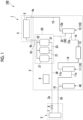
Fig. 1 is a diagram showing a refrigerant circuit according to a first embodiment of the present disclosure. -
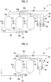
Fig. 2 is a diagram showing a medium-pressure circuit according to the first embodiment of the present disclosure. -
Fig. 3 is a diagram showing a medium-pressure circuit according to a modification example of the first embodiment of the present disclosure. -
Fig. 4 is a diagram showing a medium-pressure circuit according to a second embodiment of the present disclosure. -
Fig. 5 is a diagram showing a medium-pressure circuit according to a first modification example of the second embodiment of the present disclosure. -
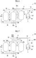
Fig. 6 is a diagram showing a medium-pressure circuit according to a second modification example of the second embodiment of the present disclosure. -
Fig. 7 is a diagram showing a medium-pressure circuit according to a third embodiment of the present disclosure. -
Fig. 8 is a diagram showing a medium-pressure circuit according to a fourth embodiment of the present disclosure. - Hereinafter, a refrigerating
apparatus 100 including an outdoor unit 1 according to a first embodiment of the present disclosure will be described with reference toFigs. 1 and2 . The refrigeratingapparatus 100 is used in, for example, a cold storage. - As shown in
Fig. 1 , the refrigeratingapparatus 100 includes the outdoor unit 1 and an indoor unit 2. - The outdoor unit 1 is a condensing unit including a
first unit 3 and a second unit 4. Thefirst unit 3 includes acompression portion 10, anintermediate heat exchanger 13, a medium-pressure circuit 20, agas injection circuit 30, anaccumulator 40, and acontrol device 6. The second unit 4 includes a condenser 5. The indoor unit 2 includes an evaporator 7 that functions as a heat exchanger on a use side. - The refrigerant circuit according to the present embodiment includes the
compression portion 10, theintermediate heat exchanger 13, the medium-pressure circuit 20, theaccumulator 40, the condenser 5, and the evaporator 7, pipes that connect these components, acontrol valve 35, and the like. - The
compression portion 10 compresses the refrigerant and supplies the compressed high-temperature and high-pressure refrigerant to the refrigerant circuit. For example, CO2 is used as the refrigerant. Thecompression portion 10 is configured in a two-stage compression type. Thecompression portion 10 includes afirst compressor 11 and asecond compressor 12. Thefirst compressor 11 and thesecond compressor 12 are connected in series. Thefirst compressor 11 is a low-stage compression element, and thesecond compressor 12 is a high-stage compression element. - Hereinafter, the circulation direction of the refrigerant is simply referred to as a "circulation direction". In the circulation direction, the
first compressor 11 is the most upstream, an upstream in the circulation direction is simply referred to as "upstream", and a downstream in the circulation direction is simply referred to as "downstream". - A
first suction pipe 11a and afirst ejection pipe 11b are connected to thefirst compressor 11. Asecond suction pipe 12a and asecond ejection pipe 12b are connected to thesecond compressor 12. Thefirst ejection pipe 11b and thesecond suction pipe 12a are connected by anintermediate flow path 14. - The
intermediate heat exchanger 13 is provided in theintermediate flow path 14. That is, theintermediate heat exchanger 13 is provided between thefirst compressor 11 and thesecond compressor 12 in the circulation direction. The intermediate heat exchanger 13 functions as a cooler that cools the refrigerant ejected from thefirst compressor 11 and that supplies the cooled refrigerant to thesecond compressor 12. - The refrigerant supplied to the
second compressor 12 is ejected through thesecond ejection pipe 12b. Agas pipe 15 is connected to thesecond ejection pipe 12b. The high-temperature and high-pressure refrigerant ejected from thesecond compressor 12 flows through thegas pipe 15. - The refrigerant flowing through the
gas pipe 15 is supplied to the condenser 5 in the second unit 4 outside through a first connectingpipe 4a. The condenser 5 functions as a gas cooler that condenses the refrigerant. The refrigerant supplied to the condenser 5 is condensed by heat exchange with air sent by a fan (not shown). In a case of the CO2 refrigerant, the CO2 refrigerant is cooled. - The refrigerant cooled or condensed by the condenser 5 is returned to a gas-liquid two-
phase pipe 16 in thefirst unit 3 through a second connectingpipe 4b. As shown inFig. 2 , the refrigerant flowing through the gas-liquid two-phase pipe 16 is expanded by afirst expansion valve 17 provided in the gas-liquid two-phase pipe 16. In a case of the CO2 refrigerant, the pressure is reduced to, for example, a medium pressure of about 6 MPa. The refrigerant in the gas-liquid two-phase state that has passed through thefirst expansion valve 17 is supplied to the medium-pressure circuit 20. The medium-pressure circuit 20 includes asupply pipe 22, areceiver 21, and adischarge pipe 23. - The
supply pipe 22 includes adistribution portion 22a and a supply-side connecting pipe 22b. Thedistribution portion 22a is a header pipe connected to the downstream side of thefirst expansion valve 17 of the gas-liquid two-phase pipe 16. Three discharge ports are provided in thedistribution portion 22a. The supply-side connecting pipes 22b are connected to the three discharge ports of thedistribution portion 22a, respectively. - Three supply-
side connecting pipes 22b are provided. The three supply-side connecting pipes 22b are all formed to have the same length. Specifically, the difference between the length of the longest supply-side connecting pipe 22b and the length of the shortest supply-side connecting pipe 22b is 0 mm or more and 800 mm or less. Onereceiver 21 is connected to each supply-side connecting pipe 22b. - Three
receivers 21 are provided. Each of thereceivers 21 is formed to have the same shape and size. Thereceiver 21 is a pressure vessel having abody portion 21a and amirror plate 21b. Thebody portion 21a is formed in a cylindrical shape in which an axial direction coincides with an up-down direction. Themirror plate 21b is provided at both end portions of thebody portion 21a in the axial direction. Themirror plate 21b is formed in a dome shape that protrudes outward in the axial direction of thebody portion 21a as themirror plate 21b is separated from thebody portion 21a. In addition, other devices such as the above-describedintermediate heat exchanger 13 are disposed above thereceiver 21. - The refrigerant in the gas-liquid two-phase state that is expanded by the
first expansion valve 17 is distributed to each of thereceivers 21 by thedistribution portion 22a and is supplied to each of thereceivers 21 through each supply-side connecting pipe 22b. Each of thereceivers 21 separates the refrigerant in the gas-liquid two-phase state into a gas refrigerant that is a gas-phase refrigerant and a liquid refrigerant that is a liquid-phase refrigerant, and stores the liquid refrigerant. Each of thereceivers 21 is provided with a liquidlevel detection portion 33 that detects a liquid level of the liquid refrigerant stored inside thereceiver 21. - The liquid
level detection portion 33 provided in each of thereceivers 21 constitutes thegas injection circuit 30 that returns the gas refrigerant in thereceiver 21 to thecompression portion 10. Thegas injection circuit 30 includes agas injection pipe 32, thecontrol valve 35, and the liquidlevel detection portion 33. - The
gas injection pipe 32 discharges the gas refrigerant from thereceiver 21. Thegas injection pipe 32 is provided in each of thereceivers 21. That is, onegas injection pipe 32 is provided in each of all thereceivers 21. The connecting portion between thegas injection pipe 32 and thereceiver 21 is provided at an upper portion of thereceiver 21 and below the connecting portion between thereceiver 21 and thesupply pipe 22. Astrainer 34 is provided in eachgas injection pipe 32. The respectivegas injection pipes 32 merge on the downstream side and are connected to the medium-pressure portion of thesecond compressor 12. The gas refrigerant flowing through thegas injection pipe 32 is returned to thesecond compressor 12 through thestrainer 34. - The
control valve 35 is provided in eachgas injection pipe 32. Thecontrol valve 35 is anelectromagnetic control valve 35 that regulates the flow rate of the gas refrigerant in thegas injection pipe 32. - The liquid
level detection portion 33 is provided at an upper portion of thereceiver 21 and below the connection between thereceiver 21 and thegas injection pipe 32. The liquidlevel detection portion 33 is a level switch that detects the liquid level of the liquid refrigerant via contact. In a case where the level switch detects the liquid level, the level switch transmits a signal indicating the increase in the liquid level to the control device 6 (seeFig. 1 ). - The
control device 6 adjusts the opening degree of thecontrol valve 35, based on the detection result of the liquidlevel detection portion 33. In the present embodiment, thecontrol device 6 switches the opening and closing of thecontrol valve 35 based on the signal from the level switch. - The
control device 6 is connected not only to thecontrol valve 35 but also to each sensor (not shown), thecompression portion 10, and various valves. Thecontrol device 6 acquires the measured value from each sensor, adjusts the rotation speed of thecompression portion 10 and the opening and closing of various valves, and operates the outdoor unit 1. - The
discharge pipe 23 discharges the liquid refrigerant from thereceiver 21. Thedischarge pipe 23 is connected to a lower portion of each of thereceivers 21. Thedischarge pipe 23 includes a discharge-side connecting pipe 23b and a mergingportion 23a. - One supply-
side connecting pipe 22b is provided at the lower portion of each of thereceivers 21. That is, three discharge-side connecting pipes 23b are provided. The three discharge-side connecting pipes 23b are all formed to have the same length. Specifically, the difference between the length of the longest discharge-side connecting pipe 23b and the length of the shortest discharge-side connecting pipe 23b is 0 mm or more and 800 mm or less. - The merging
portion 23a is a header pipe connected to the three discharge-side connecting pipes 23b. Aliquid pipe 36 is connected to the mergingportion 23a. - The liquid refrigerant in each of the
receivers 21 is discharged to theliquid pipe 36 through thedischarge pipe 23. A supercooling heat exchanger (not shown) is provided in theliquid pipe 36. The refrigerant that flows through theliquid pipe 36 is cooled by the supercooling heat exchanger and is supplied to the indoor unit 2 through a third connectingpipe 2a. - The indoor unit 2 is a unit cooler including a
second expansion valve 8 and the evaporator 7. The refrigerant supplied to the indoor unit 2 is decompressed by thesecond expansion valve 8, performs heat exchange in the evaporator 7, and cools the object. The refrigerant after heat exchange returns to the outdoor unit 1 through a fourth connectingpipe 2b. - The fourth connecting
pipe 2b is connected to areturn pipe 41 in the outdoor unit 1. The refrigerant flowing through the fourth connectingpipe 2b is supplied to theaccumulator 40 through thereturn pipe 41. Theaccumulator 40 is connected to thefirst compressor 11 through thefirst suction pipe 11a. Theaccumulator 40 performs gas-liquid separation of the refrigerant supplied to thefirst compressor 11. The gas refrigerant from which only the gas phase has been extracted by theaccumulator 40 is supplied to the suction side of thefirst compressor 11. - In a case where other devices, such as the
intermediate heat exchanger 13, are disposed above thereceiver 21, in order to increase the size of thereceiver 21, the size of thereceiver 21 is required to be increased in the radial direction. In a case where thereceiver 21 has a predetermined capacity or less, thebody portion 21a of thereceiver 21 can be manufactured by using a tube material formed in a tubular shape in advance. However, in a case where thereceiver 21 has a predetermined capacity or more, it is necessary to manufacture thebody portion 21a by rolling and welding a plurality of flat plates via press molding, or the like. In addition, as the size of thereceiver 21 is increased, the thickness of themirror plate 21b of thereceiver 21 is increased. Therefore, a large press machine is required for processing themirror plate 21b. Therefore, in a case where the size of thereceiver 21 is increased, the manufacturing cost is increased. - Meanwhile, the outdoor unit 1 of the present embodiment includes, in the medium-
pressure circuit 20, a plurality of thereceivers 21, thesupply pipe 22 that supplies the refrigerant to each of thereceivers 21, and thedischarge pipe 23 that discharges the liquid refrigerant from each of thereceivers 21. Thesupply pipe 22 includes thedistribution portion 22a that distributes the refrigerant to each of thereceivers 21. As a result, the liquid refrigerant can be distributed to the plurality ofreceivers 21. As a result, it is possible to reduce the size of each of thereceivers 21 as compared with a case in which only onereceiver 21 is provided. Therefore, since each of thereceivers 21 can be manufactured by using a ready-made tube material, thereceiver 21 can be easily manufactured. In addition, the size of themirror plate 21b can be reduced. Therefore, it is not necessary to use the large press machine. Therefore, according to the present embodiment, it is possible to reduce the manufacturing cost. - In addition, since the size of the
receiver 21 can be reduced, it is easy to adjust the disposition of thereceiver 21 in the outdoor unit 1 in which various devices and pipes are present, and the weight of each of thereceivers 21 is reduced. As a result, thereceiver 21 is easily handled. In addition, since the weight of each of thereceivers 21 is reduced, it is possible to easily secure the strength required to support the weight of thereceiver 21. - In addition, each of the
receivers 21 is one unit including thedistribution portion 22a and the supply-side connecting pipe 22b, and the mergingportion 23a and the discharge-side connecting pipe 23b. Accordingly, thereceiver 21 is further facilitated to handle. - Therefore, it is possible to reduce the design constraints from the viewpoint of manufacturing cost, handling, and the like.
- In the outdoor unit 1 of the present embodiment, the
gas injection pipe 32 is provided in each of thereceivers 21. As a result, the height of the liquid level of the liquid refrigerant to be stored can be made uniform in each of thereceivers 21. Therefore, it is possible to manage the gas-liquid separation of the refrigerant for each of thereceivers 21, and thus, it is possible to improve controllability. - In addition, the outdoor unit 1 includes the liquid
level detection portion 33 that detects the liquid level of the liquid refrigerant stored in thereceiver 21, thecontrol valve 35 that regulates the flow rate of the gas refrigerant in thegas injection pipe 32, and thecontrol device 6 that controls the opening degree of thecontrol valve 35 in thegas injection pipe 32 based on the detection result of the liquidlevel detection portion 33. Accordingly, the gas-liquid separation of the refrigerant can be automated, and thus the gas-liquid separation of the refrigerant can be easily managed. - In addition, one liquid
level detection portion 33 is provided in each of thereceivers 21. Accordingly, it is possible to easily manage the gas-liquid separation of the refrigerant of each of thereceivers 21. - In the outdoor unit 1 of the present embodiment, the difference between the length of the longest supply-
side connecting pipe 22b and the length of the shortest supply-side connecting pipe 22b is 0 mm or more and 800 mm or less, and the difference between the length of the longest discharge-side connecting pipe 23b and the length of the shortest discharge-side connecting pipe 23b is 0 mm or more and 800 mm or less. Accordingly, it is possible to suppress a difference in pressure loss between the plurality ofreceivers 21 in a case of supplying the refrigerant and in a case of discharging the liquid refrigerant. Accordingly, the liquid levels of the liquid refrigerants to be stored are likely to be made uniform in therespective receivers 21, and thus it is possible to easily manage the gas-liquid separation of the refrigerant for each of thereceivers 21. Therefore, controllability can be improved. - A modification example of the first embodiment will be described with reference to
Fig. 3 . In the first embodiment, threereceivers 21 are provided. Meanwhile, in this modification example, tworeceivers 21 are provided. - Hereinafter, an
outdoor unit 1A according to a second embodiment of the present disclosure will be described with reference toFig. 4 . In the second embodiment, the same reference numerals will be assigned to configuration elements which are the same as those according to the first embodiment, and detailed description thereof will be appropriately omitted. Theoutdoor unit 1A of the second embodiment further includes a communicatingpipe 31 through which each of thereceivers 21 communicates in a medium-pressure circuit 20A. - As shown in
Fig. 4 , the plurality ofreceivers 21 are provided in the medium-pressure circuit 20A. In the present embodiment, the number of thereceivers 21 in the medium-pressure circuit 20A is two. - All the
receivers 21 in the medium-pressure circuit 20A communicate with each other through the communicatingpipe 31. The inner diameter of the communicatingpipe 31 is, for example, 22.22 mm. The liquidlevel detection portion 33 is provided only in onereceiver 21 of the plurality ofreceivers 21. - In the
outdoor unit 1A of the present embodiment, the liquid refrigerant can be made to be able to flow between all thereceivers 21 by the communicatingpipe 31. As a result, the height of the liquid level of the liquid refrigerant stored in each of thereceivers 21 can be made uniform. Therefore, it is possible to easily manage the height of the liquid level of the liquid refrigerant, and thus, it is possible to improve controllability. - In addition, since the plurality of
receivers 21 communicate with each other through the communicatingpipe 31, the gas refrigerant can be moved between the plurality ofreceivers 21. As a result, the plurality ofreceivers 21 are pressurized in a uniform manner. - Further, since the
gas injection pipe 32 is provided in each of thereceivers 21 and the communicatingpipe 31 through which all thereceivers 21 communicate with each other is provided, the probability that a difference in the height of the liquid level of the liquid refrigerant occurs in each of thereceivers 21 can be extremely low. Accordingly, the height of the liquid level of the liquid refrigerant can be sufficiently managed by simply providing the liquidlevel detection portion 33 in onereceiver 21 of the plurality ofreceivers 21. Therefore, it is possible to simplify the outdoor unit 1 and reduce the manufacturing cost as compared with a case in which the liquidlevel detection portion 33 is provided in all thereceivers 21. - A first modification example of the second embodiment will be described with reference to
Fig. 5 . - As shown in
Fig. 5 , in anoutdoor unit 1B of the present modification example, the number of thereceivers 21 in a medium-pressure circuit 20B is three. The lengths of thereceivers 21 in the up-down direction are the same. Specifically, a difference between a length of thereceiver 21 in the up-down direction, which has a longest length in the up-down direction, and a length of thereceiver 21 in the up-down direction, which has a shortest length in the up-down direction, is 0 mm or more and 800 mm or less. In addition, in the present embodiment, each of thereceivers 21 is formed to have the same shape and size. Thegas injection pipe 32 is provided only in onereceiver 21 among the threereceivers 21, and the liquidlevel detection portion 33 is provided only in thereceiver 21 in which thegas injection pipe 32 is provided. - The
gas injection pipe 32 of the present modification example branches into two pipes in the intermediate portion in the circulation direction. Onestrainer 34 and onecontrol valve 35 are provided in each of the branchinggas injection pipes 32. - A plurality of the communicating
pipes 31 are provided. Any tworeceivers 21 among the plurality ofreceivers 21 communicate with each other through each of thereceivers 21 to form one set of thereceivers 21. In each set of thereceivers 21, two communicatingpipes 31 are provided to be separated from each other in the up-down direction. Of the two communicatingpipes 31 separated from each other in the up-down direction, the upper communicatingpipe 31 mainly functions to move the gas refrigerant between thereceivers 21, and the lower communicatingpipe 31 mainly functions to move the liquid refrigerant between thereceivers 21. The communicatingpipes 31 belonging to different sets are provided at positions overlapping with each other in the up-down direction. That is, the upper communicatingpipes 31 belonging to different sets are provided at positions overlapping with each other in the up-down direction, and the lower communicatingpipes 31 belonging to different sets are provided at positions overlapping with each other in the up-down direction. - In the present modification example, since the communicating
pipe 31 through which all thereceivers 21 communicate with each other is provided, the probability that a difference in the height of the liquid level of the liquid refrigerant occurs in each of thereceivers 21 can be low. Accordingly, the height of the liquid level of the liquid refrigerant can be sufficiently managed by simply providing the liquidlevel detection portion 33 only in thereceiver 21 in which thegas injection pipe 32 is provided. Therefore, it is possible to simplify the outdoor unit 1 and reduce the manufacturing cost as compared with a case in which thegas injection pipe 32 and the liquidlevel detection portion 33 are provided in all thereceivers 21. - In the present modification example, the plurality of communicating
pipes 31 are provided to be separated from each other in the up-down direction. As a result, the height of the liquid level stored in each of thereceivers 21 can be made uniform at an early stage of refrigerant storage. Therefore, it is possible to further easily manage the height of the liquid refrigerant, and thus, it is possible to further improve controllability. - In the present modification example, the communicating
pipes 31 belonging to different sets of thereceivers 21 are provided at positions overlapping with each other in the up-down direction. Accordingly, in all thereceivers 21, the height of the liquid level at which the liquid refrigerant starts to flow to theother receivers 21 can be made uniform. Therefore, it is possible to further easily manage the height of the liquid refrigerant regardless of the number ofreceivers 21, and thus, it is possible to further improve controllability. - In the present modification example, the difference between the length of the
receiver 21 in the up-down direction, which has the longest length in the up-down direction, and the length of thereceiver 21 in the up-down direction, which has the shortest length in the up-down direction, is 0 mm or more and 800 mm or less. As a result, the acceptable height of the liquid refrigerant can be made uniform between the plurality ofreceivers 21. Therefore, it is possible to further easily manage the height of the liquid level of the liquid refrigerant stored in thereceiver 21, and thus, it is possible to further improve controllability. - The present modification example has described a case where two communicating
pipes 31 are provided in each set of thereceivers 21 communicating with each other through the communicatingpipe 31, but the present disclosure is not limited to this, and three or more communicatingpipes 31 may be provided in each set of thereceivers 21. - In the present modification example, the case where the
gas injection pipe 32 is provided only in onereceiver 21 among the threereceivers 21 has been described, but the present disclosure is not limited to this, and thegas injection pipe 32 may be provided in each of some two ormore receivers 21. In this case, one liquidlevel detection portion 33 is provided in each of thereceivers 21 in which thegas injection pipe 32 is provided. - A second modification example of the second embodiment will be described with reference to
Fig. 6 . - As shown in
Fig. 6 , in a medium-pressure circuit 20C of an outdoor unit 1C of the present modification example, onereceiver 21 in which thegas injection pipe 32 is provided among the threereceivers 21 is disposed above theother receivers 21 by, for example, 100 mm. That is, an upper end of onereceiver 21 in which thegas injection pipe 32 is provided among the threereceivers 21 is positioned above upper ends of theother receivers 21. Accordingly, a space filled with the gas refrigerant can be left above thereceiver 21 in which thegas injection pipe 32 is provided. Therefore, all the capacities of theother receivers 21 not provided with thegas injection pipe 32 can be utilized for storing the liquid refrigerant. - Here, as a third modification example of the outdoor unit 1C of the second embodiment, the outdoor unit 1C may be adopted in which one
receiver 21 in which thegas injection pipe 32 is provided in the second modification example described above is formed to be longer than theother receivers 21 in the up-down direction. Accordingly, the capacity of somereceivers 21 in which thegas injection pipe 32 is provided can be increased. - Hereinafter, an
outdoor unit 1D according to a third embodiment of the present disclosure will be described with reference toFig. 7 . In the third embodiment, the same reference numerals will be assigned to configuration elements which are the same as those according to each embodiment described above, and detailed description thereof will be appropriately omitted. In a medium-pressure circuit 20D of theoutdoor unit 1D of the third embodiment, thedistribution portion 22a performs gas-liquid separation of the refrigerant. - The
distribution portion 22a is a distribution pipe 22a1 that performs gas-liquid separation on the refrigerant into the liquid refrigerant and the gas refrigerant and that stores the liquid refrigerant. The distribution pipe 22a1 is formed to extend in one direction. The distribution pipe 22a1 is disposed to extend obliquely with respect to the horizontal direction. Thegas injection pipe 32 is connected to the distribution pipe 22a1. The connecting portion between thegas injection pipe 32 and the distribution pipe 22a1 is disposed above the connecting portion between the supply-side connecting pipe 22b and the distribution pipe 22a1. The liquidlevel detection portion 33 is provided in the distribution pipe 22a1. The liquidlevel detection portion 33 is provided above the connecting portion between the supply-side connecting pipe 22b and the distribution pipe 22a1 and below the connecting portion between thegas injection pipe 32 and the distribution pipe 22a1. - In the present embodiment, the refrigerant can be subjected to gas-liquid separation by the
distribution portion 22a on the upstream side of thereceiver 21. Accordingly, since it is possible to utilize all the capacity of thereceiver 21 for storing the liquid refrigerant, it is not necessary to provide a space filled with the gas refrigerant in each of thereceivers 21. Therefore, since the size of each of thereceivers 21 can be further reduced, it is possible to further reduce the design constraints. - In addition, the
distribution portion 22a is the distribution pipe 22a1 that extends in one direction. Accordingly, for example, even in a case where other devices such as theintermediate heat exchanger 13 are disposed above thereceiver 21, a mechanism for gas-liquid separation of the refrigerant can be provided in a relatively narrow space between thereceiver 21 and the other devices. Therefore, it is possible to further reduce the design constraints. - In addition, the distribution pipe 22a1 is disposed obliquely with respect to the horizontal direction. Accordingly, the time at which the liquid
level detection portion 33 detects the liquid level of the liquid refrigerant can be delayed as compared with a case where the distribution pipe 22a1 is disposed along the horizontal direction. Therefore, the capacity of the distribution pipe 22a1 can be further utilized. - In the present embodiment, the
distribution portion 22a is the distribution pipe 22a1. However, the present disclosure is not limited thereto, and thedistribution portion 22a may be an auxiliary tank for storage. - Hereinafter, an
outdoor unit 1E according to a fourth embodiment of the present disclosure will be described with reference toFig. 8 . In the fourth embodiment, the same reference numerals will be assigned to configuration elements which are the same as those according to each embodiment described above, and detailed description thereof will be appropriately omitted. In a medium-pressure circuit 20E of theoutdoor unit 1E of the fourth embodiment, the refrigerant is directly supplied to onereceiver 21 among the plurality ofreceivers 21 by onesupply pipe 22. - As shown in
Fig. 8 , theoutdoor unit 1E of the present embodiment includes the medium-pressure circuit 20E, thegas injection circuit 30, and the control device 6 (seeFig. 1 ). The medium-pressure circuit 20E includes thereceiver 21, thesupply pipe 22, the communicatingpipe 31, and thedischarge pipe 23. - The plurality of receivers 21 (three in the present embodiment) are provided. All the
receivers 21 are formed to have the same shape and size, and are disposed at the same position in the up-down direction. - One
supply pipe 22 is provided in onereceiver 21 among the plurality ofreceivers 21. Thesupply pipe 22 connects the gas-liquid two-phase pipe 16 and thereceiver 21. - The communicating
pipe 31 is provided between the plurality ofreceivers 21. The plurality of communicatingpipes 31 are provided to be separated from each other in the up-down direction. The communicatingpipes 31 belonging to different sets of thereceivers 21 of sets of thereceivers 21 communicating with each other through the communicatingpipe 31 are provided at positions overlapping with each other in the up-down direction. - In addition, the communicating
pipe 31 connects theadjacent receivers 21 to each other, and onereceiver 21 to which thesupply pipe 22 is connected and the remainingreceivers 21 communicate with each other through the communicatingpipe 31. In the present embodiment, for each set of theadjacent receivers 21, two communicatingpipes 31 are provided, one above and one below. Of the two communicatingpipes 31 disposed above and below, the upper communicatingpipe 31 mainly functions to move the gas refrigerant between thereceivers 21, and the lower communicatingpipe 31 mainly functions to move the liquid refrigerant between thereceivers 21. - The
discharge pipe 23 discharges the liquid refrigerant from each of thereceivers 21. Thedischarge pipe 23 includes the mergingportion 23a and the discharge-side connecting pipe 23b. In the mergingportion 23a, the liquid refrigerants discharged from therespective receivers 21 merge. One discharge-side connecting pipe 23b is provided in each of thereceivers 21. The discharge-side connecting pipe 23b connects the mergingportion 23a and each of thereceivers 21. - The
gas injection circuit 30 includes thegas injection pipe 32, thecontrol valve 35, and the liquidlevel detection portion 33. - The
gas injection pipe 32 is provided in onereceiver 21 to which thesupply pipe 22 is connected. Thegas injection pipe 32 discharges the gas refrigerant of the refrigerant from thereceiver 21. - The liquid
level detection portion 33 is provided in onereceiver 21 in which thegas injection pipe 32 is provided. The liquidlevel detection portion 33 is provided in themirror plate 21b of thereceiver 21 and is positioned below the connecting portion between thesupply pipe 22 and thereceiver 21. The liquidlevel detection portion 33 detects the liquid level of the liquid refrigerant stored in onereceiver 21. - The
control valve 35 is provided in thegas injection pipe 32 and regulates the flow rate of the gas refrigerant in thegas injection pipe 32. - The
control device 6 controls the opening degree of thecontrol valve 35, based on the detection result of the liquidlevel detection portion 33. - In the
outdoor unit 1E of the present embodiment, the refrigerant is directly supplied from thesupply pipe 22 to onereceiver 21 in which the liquidlevel detection portion 33 is provided among the plurality ofreceivers 21. The gas refrigerant of the refrigerant supplied into thereceiver 21 is distributed to theother receivers 21 through the communicatingpipe 31. As a result, the plurality ofreceivers 21 are pressurized in a uniform manner. The gas refrigerant is drawn out of thereceiver 21 through thegas injection pipe 32. - Further, the liquid refrigerant of the refrigerant supplied into the
receiver 21 is temporarily stored in thereceiver 21 and is transferred to the downstream side through thedischarge pipe 23. In a case where the liquid refrigerant stored in thereceiver 21 reaches the height of the lower communicatingpipe 31, the liquid refrigerant is supplied into theother receivers 21 through the communicatingpipe 31. - In this way, the refrigerant is distributed to the plurality of
receivers 21 in a well-balanced manner. - In the present embodiment, the
outdoor unit 1E includes the plurality ofreceivers 21 that store the liquid refrigerant of the refrigerant, thesupply pipe 22 that is connected to one of the plurality ofreceivers 21 and supplies the refrigerant to the onereceiver 21, the communicatingpipe 31 through which the onereceiver 21 and the remainingreceivers 21 communicate with each other, and thedischarge pipe 23 that discharges the liquid refrigerant from each of thereceivers 21, in which thedischarge pipe 23 includes the mergingportion 23a in which the liquid refrigerant discharged from each of thereceivers 21 merges, and a plurality of the discharge-side connecting pipes 23b that connect the mergingportion 23a and each of the receivers. - Accordingly, it is possible to distribute the gas refrigerant to the plurality of
receivers 21 while the liquid refrigerant is stored in onereceiver 21. As a result, it is possible to reduce the size of each of thereceivers 21 as compared with a case in which only onereceiver 21 is provided. Therefore, according to the present embodiment, it is possible to reduce the manufacturing cost of the entire device and to facilitate the handling of thereceiver 21. Therefore, it is possible to reduce the design constraints from the viewpoint of manufacturing cost, handling, and the like. - In the present embodiment, the plurality of communicating
pipes 31 are provided to be separated from each other in the up-down direction. - As a result, the height of the liquid level stored in each of the
receivers 21 can be made uniform at an early stage of refrigerant storage mainly by the lower communicatingpipe 31. Therefore, it is possible to easily manage the height of the liquid refrigerant, and thus, it is possible to improve controllability. As a result, the gas refrigerant can be moved between thereceivers 21 mainly by the upper communicatingpipe 31. - In the present embodiment, three
receivers 21 are provided. Further, the communicatingpipes 31 belonging to different sets of thereceivers 21 of sets of thereceivers 21 communicating with each other through the communicatingpipe 31 are provided at positions overlapping with each other in the up-down direction. - Accordingly, in all the
receivers 21, the height of the liquid level at which the liquid refrigerant starts to flow to theother receivers 21 can be made uniform. Therefore, it is possible to further easily manage the height of the liquid refrigerant regardless of the number ofreceivers 21, and thus, it is possible to further improve controllability. - In the present embodiment, the
outdoor unit 1E includes thegas injection pipe 32 that is provided in the onereceiver 21 to which thesupply pipe 22 is connected and that discharges the gas refrigerant of the refrigerant from thereceiver 21, the liquidlevel detection portion 33 that is provided in the onereceiver 21 in which thegas injection pipe 32 is provided and that detects the liquid level of the liquid refrigerant stored in the onereceiver 21, thecontrol valve 35 that is provided in thegas injection pipe 32 and regulates the flow rate of the gas refrigerant in thegas injection pipe 32, and thecontrol device 6 that controls the opening degree of thecontrol valve 35 based on the detection result of the liquidlevel detection portion 33. - Therefore, it is possible to simplify the
outdoor unit 1E and reduce the manufacturing cost as compared with a case in which thegas injection pipe 32 and the liquidlevel detection portion 33 are provided in all thereceivers 21. - In the present embodiment, for each set of the
adjacent receivers 21, two communicatingpipes 31 are provided, one above and one below. However, the present disclosure is not limited to this. Only one communicatingpipe 31 may be provided for each set of theadjacent receivers 21, and for example, the lower communicatingpipe 31 of the two communicatingpipes 31 need not be provided. - In the present embodiment, all the
receivers 21 are formed to have the same shape and size, and are disposed at the same position in the up-down direction, but the present disclosure is not limited to this. For example, the shapes of the plurality ofreceivers 21 may be different from each other. In addition, thereceiver 21 in which thegas injection pipe 32 is provided among the plurality ofreceivers 21 may be longer than theother receivers 21 in the up-down direction. In addition, the plurality ofreceivers 21 may be disposed such that the upper end of thereceiver 21 in which thegas injection pipe 32 is provided among the plurality ofreceivers 21 is positioned above the upper ends of theother receivers 21. - In addition, the number of the
receivers 21 can be changed as appropriate. - The embodiments of the present disclosure have been described in detail with reference to the drawings hereinbefore. However, the specific configuration is not limited to the embodiments, and includes design changes and the like within a scope not departing from the gist of the present disclosure. Each embodiment and each modification example which are described above may be appropriately combined.
- In the above-described embodiment, the refrigerating
apparatus 100 is used for the cold storage or the like. However, the present disclosure is not limited thereto, and the refrigeratingapparatus 100 may be used for air conditioning of an office building, a commercial facility, a factory, or the like. - In the above-described embodiment, for example, CO2 is used as the refrigerant, but the present disclosure is not limited thereto. For example, propane gas, butane, propylene, or the like may be used as the refrigerant.
- In the above-described embodiment, the number of the
receivers 21 in the medium-pressure circuits receivers 21 may be four or more. - In the
outdoor units pipes 31 may be provided to be separated from each other in the up-down direction. In addition, in theoutdoor units more receivers 21 may be provided, and the communicatingpipes 31 belonging to different sets of sets of thereceivers 21 communicating with each other through the communicatingpipe 31 may be provided at positions overlapping with each other in the up-down direction. - The
outdoor units -
- (1) An
outdoor unit 1E according to a first aspect includes a plurality ofreceivers 21 that store a liquid refrigerant of a refrigerant, asupply pipe 22 that is connected to one of the plurality ofreceivers 21 and supplies the refrigerant to the onereceiver 21, a communicatingpipe 31 through which the onereceiver 21 and the remainingreceivers 21 communicate with each other, and adischarge pipe 23 that discharges the liquid refrigerant from each of thereceivers 21, in which thedischarge pipe 23 includes a mergingportion 23a in which the liquid refrigerant discharged from each of thereceivers 21 merges, and a plurality of discharge-side connecting pipes 23b that connect the mergingportion 23a and each of thereceivers 21. - Accordingly, it is possible to distribute the gas refrigerant to the plurality of
receivers 21 while the liquid refrigerant is stored in onereceiver 21. As a result, it is possible to reduce the size of each of thereceivers 21 as compared with a case in which only onereceiver 21 is provided. Therefore, it is possible to reduce the design constraints. - (2) An
outdoor unit 1E of a second aspect is theoutdoor unit 1E of the first aspect, in which a plurality of the communicatingpipes 31 may be provided to be separated from each other in an up-down direction. - As a result, the height of the liquid level stored in each of the
receivers 21 can be made uniform at an early stage of refrigerant storage mainly by the lower communicatingpipe 31. Therefore, it is possible to easily manage the height of the liquid refrigerant. As a result, the gas refrigerant can be moved between thereceivers 21 mainly by the upper communicatingpipe 31. - (3) An
outdoor unit 1E of a third aspect is theoutdoor unit 1E of the first or second aspect, in which three ormore receivers 21 may be provided, and the communicatingpipes 31 belonging to different sets of sets of thereceivers 21 communicating with each other through the communicatingpipe 31 may be provided at positions overlapping with each other in an up-down direction. - Accordingly, in all the
receivers 21, the height of the liquid level at which the liquid refrigerant starts to flow to theother receivers 21 can be made uniform. Therefore, it is possible to further easily manage the height of the liquid refrigerant regardless of the number ofreceivers 21. - (4) An
outdoor unit 1E of a fourth aspect is theoutdoor unit 1E of any one of the first to third aspects, and may include agas injection pipe 32 that is provided in the onereceiver 21 to which thesupply pipe 22 is connected and that discharges a gas refrigerant of the refrigerant from thereceiver 21, a liquidlevel detection portion 33 that is provided in the onereceiver 21 in which thegas injection pipe 32 is provided and that detects a liquid level of the liquid refrigerant stored in the onereceiver 21, acontrol valve 35 that is provided in thegas injection pipe 32 and regulates a flow rate of the gas refrigerant in thegas injection pipe 32, and acontrol device 6 that controls an opening degree of thecontrol valve 35 based on a detection result of the liquidlevel detection portion 33. - Therefore, it is possible to simplify the
outdoor unit 1E and reduce the manufacturing cost as compared with a case in which thegas injection pipe 32 and the liquidlevel detection portion 33 are provided in all thereceivers 21. - (5) An
outdoor unit receivers 21 that store a liquid refrigerant of a refrigerant, asupply pipe 22 that supplies the refrigerant to each of thereceivers 21, and adischarge pipe 23 that discharges the liquid refrigerant from each of thereceivers 21, in which thesupply pipe 22 includes adistribution portion 22a that distributes the refrigerant to each of thereceivers 21, and a plurality of supply-side connecting pipes 22b that connect thedistribution portion 22a and each of thereceivers 21, and thedischarge pipe 23 includes a mergingportion 23a in which the liquid refrigerant discharged from each of thereceivers 21 merges, and a plurality of discharge-side connecting pipes 23b that connect the mergingportion 23a and each of thereceivers 21. - As a result, the liquid refrigerant can be distributed to the plurality of
receivers 21. As a result, it is possible to reduce the size of each of thereceivers 21 as compared with a case in which only onereceiver 21 is provided. Therefore, it is possible to reduce the design constraints. - (6) An
outdoor unit 1, 1A of a sixth aspect is theoutdoor unit 1, 1A of the fifth aspect, and may include a plurality ofgas injection pipes 32 that are provided in each of thereceivers 21 and discharge a gas refrigerant of the refrigerant from thereceiver 21, a liquidlevel detection portion 33 that detects a liquid level of the liquid refrigerant stored in thereceiver 21, acontrol valve 35 that is provided in thegas injection pipe 32 and regulates a flow rate of the gas refrigerant in thegas injection pipe 32, and acontrol device 6 that controls an opening degree of thecontrol valve 35 based on a detection result of the liquidlevel detection portion 33. - Therefore, it is possible to manage the gas-liquid separation of the refrigerant for each of the
receivers 21, and thus, it is possible to improve controllability. - (7) An
outdoor unit 1D of a seventh aspect is theoutdoor unit 1D of the fifth aspect, in which thedistribution portion 22a may be a distribution pipe 22a1 that is disposed to extend obliquely with respect to a horizontal direction and that performs gas-liquid separation on the refrigerant into the liquid refrigerant and a gas refrigerant and stores the liquid refrigerant, and theoutdoor unit 1D may include agas injection pipe 32 that is provided in the distribution pipe 22a1 and discharges the gas refrigerant, and a liquidlevel detection portion 33 that is provided in the distribution pipe 22a1 and detects a liquid level of the stored liquid refrigerant. - Accordingly, the refrigerant can be subjected to gas-liquid separation by the
distribution portion 22a, and thus, the entire capacity of thereceiver 21 can be utilized for storing the liquid refrigerant. - (8) An
outdoor unit outdoor unit pipe 31 through which all of the plurality ofreceivers 21 communicate with each other. - Accordingly, the liquid refrigerant can be made to be able to flow between all the
receivers 21. As a result, the height of the liquid level of the liquid refrigerant stored in each of thereceivers 21 can be made uniform. Therefore, it is possible to easily manage the height of the liquid level of the liquid refrigerant. - (9) An
outdoor unit outdoor unit pipes 31 may be provided to be separated from each other in an up-down direction. - As a result, the height of the liquid level stored in each of the
receivers 21 can be made uniform at an early stage of refrigerant storage. Therefore, it is possible to further easily manage the height of the liquid refrigerant. - (10) An
outdoor unit outdoor unit more receivers 21 may be provided, and the communicatingpipes 31 belonging to different sets of sets of thereceivers 21 communicating with each other through the communicatingpipe 31 may be provided at positions overlapping with each other in an up-down direction. - Accordingly, in all the
receivers 21, the height of the liquid level at which the liquid refrigerant starts to flow to theother receivers 21 can be made uniform. Therefore, it is possible to further easily manage the height of the liquid refrigerant regardless of the number ofreceivers 21. - (11) An
outdoor unit 1B, 1C of an eleventh aspect is theoutdoor unit 1B, 1C of the fifth aspect, and may include a communicatingpipe 31 through which all of the plurality ofreceivers 21 communicate with each other, agas injection pipe 32 that is provided in each of somereceivers 21 among the plurality ofreceivers 21 and discharges a gas refrigerant of the refrigerant from thereceiver 21, a liquidlevel detection portion 33 that is provided in each of somereceivers 21 in which thegas injection pipe 32 is provided and that detects a liquid level of the liquid refrigerant stored in thereceiver 21, acontrol valve 35 that is provided in thegas injection pipe 32 and regulates a flow rate of the gas refrigerant in thegas injection pipe 32, and acontrol device 6 that controls an opening degree of thecontrol valve 35 based on a detection result of the liquidlevel detection portion 33. - Therefore, it is possible to simplify the
outdoor units 1B and 1C and reduce the manufacturing cost as compared with a case in which thegas injection pipe 32 and the liquidlevel detection portion 33 are provided in all thereceivers 21. - (12) An outdoor unit 1C of a twelfth aspect is the outdoor unit 1C of the eleventh aspect, in which upper ends of some
receivers 21 in which thegas injection pipe 32 is provided among the plurality ofreceivers 21 may be positioned above upper ends of theother receivers 21. - Accordingly, a space filled with the gas refrigerant can be left above the
receiver 21 in which thegas injection pipe 32 is provided. Therefore, all the capacities of theother receivers 21 not provided with thegas injection pipe 32 can be utilized for storing the liquid refrigerant. - (13) An outdoor unit 1C of a thirteenth aspect is the outdoor unit 1C of the twelfth aspect, in which some
receivers 21 in which thegas injection pipe 32 is provided among the plurality ofreceivers 21 may be longer than theother receivers 21 in an up-down direction. - Accordingly, the capacity of some
receivers 21 in which thegas injection pipe 32 is provided can be increased. - (14) An
outdoor unit 1B, 1C of a fourteenth aspect is theoutdoor unit 1B, 1C of the eleventh or twelfth aspect, in which a difference between a length of thereceiver 21 in an up-down direction, which has a longest length in the up-down direction, and a length of thereceiver 21 in the up-down direction, which has a shortest length in the up-down direction, may be 0 mm or more and 800 mm or less. - As a result, the acceptable height of the liquid refrigerant can be made uniform between the plurality of
receivers 21. As a result, the height of the liquid level of the liquid refrigerant stored in thereceiver 21 can be further easily managed. - (15) An
outdoor unit 1B, 1C of a fifteenth aspect is theoutdoor unit 1B, 1C of any one of the eleventh to fourteenth aspects, in which a plurality of the communicatingpipes 31 may be provided to be separated from each other in an up-down direction. - (16) An
outdoor unit 1B, 1C of a sixteenth aspect is theoutdoor unit 1B, 1C of any one of the eleventh to fifteenth aspects, in which three ormore receivers 21 may be provided, and the communicatingpipes 31 belonging to different sets of sets of thereceivers 21 communicating with each other through the communicatingpipe 31 may be provided at positions overlapping with each other in an up-down direction. - (17) An
outdoor unit outdoor unit side connecting pipe 22b and a length of a shortest supply-side connecting pipe 22b may be 0 mm or more and 800 mm or less, and a difference between a length of a longest discharge-side connecting pipe 23b and a length of a shortest discharge-side connecting pipe 23b may be 0 mm or more and 800 mm or less. - Accordingly, it is possible to suppress a difference in pressure loss between the plurality of
receivers 21 in a case of supplying the refrigerant and in a case of discharging the liquid refrigerant. - According to the outdoor unit of the present disclosure, it is possible to reduce design constraints.
-
- 1, 1A, 1B, 1C, 1D, 1E: outdoor unit
- 2: indoor unit
- 2a: third connecting pipe
- 2b: fourth connecting pipe
- 3: first unit
- 4: second unit
- 4a: first connecting pipe
- 4b: second connecting pipe
- 5: condenser
- 6: control device
- 7: evaporator
- 8: second expansion valve
- 10: compression portion
- 11: first compressor
- 11a: first suction pipe
- 11b: first ejection pipe
- 12: second compressor
- 12a: second suction pipe
- 12b: second ejection pipe
- 13: intermediate heat exchanger
- 14: intermediate flow path
- 15: gas pipe
- 16: gas-liquid two-phase pipe
- 17: first expansion valve
- 20, 20A, 20B, 20C, 20D, 20E: medium-pressure circuit
- 21: receiver
- 22: supply pipe
- 22a: distribution portion
- 22a1: distribution pipe
- 22b: supply-side connecting pipe
- 23: discharge pipe
- 23a: merging portion
- 23b: discharge-side connecting pipe
- 30: gas injection circuit
- 31: communicating pipe
- 32: gas injection pipe
- 33: liquid level detection portion
- 34: strainer
- 35: control valve
- 36: liquid pipe
- 40: accumulator
- 41: return pipe
- 100: refrigerating apparatus
Claims (17)
- An outdoor unit comprising:a plurality of receivers that store a liquid refrigerant of a refrigerant;a supply pipe that is connected to one receiver of the plurality of receivers and supplies the refrigerant to the one receiver;a communicating pipe through which the one receiver and the remaining receivers communicate with each other; anda discharge pipe that discharges the liquid refrigerant from each of the receivers,wherein the discharge pipe includesa merging portion in which the liquid refrigerant discharged from each of the receivers merges, anda plurality of discharge-side connecting pipes that connect the merging portion and each of the receivers.
- The outdoor unit according to Claim 1,
wherein a plurality of the communicating pipes are provided to be separated from each other in an up-down direction. - The outdoor unit according to Claim 1 or 2,wherein three or more receivers are provided, andthe communicating pipes belonging to different sets of sets of the receivers communicating with each other through the communicating pipe are provided at positions overlapping with each other in an up-down direction.
- The outdoor unit according to Claim 1 or 2, further comprising:a gas injection pipe that is provided in the one receiver to which the supply pipe is connected and that discharges a gas refrigerant of the refrigerant from the receiver;a liquid level detection portion that is provided in the one receiver in which the gas injection pipe is provided and that detects a liquid level of the liquid refrigerant stored in the one receiver;a control valve that is provided in the gas injection pipe and regulates a flow rate of the gas refrigerant in the gas injection pipe; anda control device that controls an opening degree of the control valve based on a detection result of the liquid level detection portion.
- An outdoor unit comprising:a plurality of receivers that store a liquid refrigerant of a refrigerant;a supply pipe that supplies the refrigerant to each of the receivers; anda discharge pipe that discharges the liquid refrigerant from each of the receivers,wherein the supply pipe includesa distribution portion that distributes the refrigerant to each of the receivers, anda plurality of supply-side connecting pipes that connect the distribution portion and each of the receivers, andthe discharge pipe includesa merging portion in which the liquid refrigerant discharged from each of the receivers merges, anda plurality of discharge-side connecting pipes that connect the merging portion and each of the receivers.
- The outdoor unit according to Claim 5, further comprising:a plurality of gas injection pipes that are provided in each of the receivers and discharge a gas refrigerant of the refrigerant from the receiver;a liquid level detection portion that detects a liquid level of the liquid refrigerant stored in the receiver;a control valve that is provided in the gas injection pipe and regulates a flow rate of the gas refrigerant in the gas injection pipe; anda control device that controls an opening degree of the control valve based on a detection result of the liquid level detection portion.
- The outdoor unit according to Claim 5,wherein the distribution portion is a distribution pipe that is disposed to extend obliquely with respect to a horizontal direction and that performs gas-liquid separation on the refrigerant into the liquid refrigerant and a gas refrigerant and stores the liquid refrigerant, andthe outdoor unit further comprisesa gas injection pipe that is provided in the distribution pipe and discharges the gas refrigerant, anda liquid level detection portion that is provided in the distribution pipe and detects a liquid level of the stored liquid refrigerant.
- The outdoor unit according to any one of Claims 5 to 7, further comprising:
a communicating pipe through which all of the plurality of receivers communicate with each other. - The outdoor unit according to Claim 8,
wherein a plurality of the communicating pipes are provided to be separated from each other in an up-down direction. - The outdoor unit according to Claim 8,wherein three or more receivers are provided, andthe communicating pipes belonging to different sets of sets of the receivers communicating with each other through the communicating pipe are provided at positions overlapping with each other in an up-down direction.
- The outdoor unit according to Claim 5, further comprising:a communicating pipe through which all of the plurality of receivers communicate with each other;a gas injection pipe that is provided in each of some receivers among the plurality of receivers and discharges a gas refrigerant of the refrigerant from the receiver;a liquid level detection portion that is provided in each of some receivers in which the gas injection pipe is provided and that detects a liquid level of the liquid refrigerant stored in the receiver;a control valve that is provided in the gas injection pipe and regulates a flow rate of the gas refrigerant in the gas injection pipe; anda control device that controls an opening degree of the control valve based on a detection result of the liquid level detection portion.
- The outdoor unit according to Claim 11,
wherein upper ends of some receivers in which the gas injection pipe is provided among the plurality of receivers are positioned above upper ends of the other receivers. - The outdoor unit according to Claim 12,
wherein some receivers in which the gas injection pipe is provided among the plurality of receivers are longer than the other receivers in an up-down direction. - The outdoor unit according to Claim 11 or 12,
wherein a difference between a length of the receiver in an up-down direction, which has a longest length in the up-down direction, and a length of the receiver in the up-down direction, which has a shortest length in the up-down direction, is 0 mm or more and 800 mm or less. - The outdoor unit according to any one of Claims 11 to 13,
wherein a plurality of the communicating pipes are provided to be separated from each other in an up-down direction. - The outdoor unit according to any one of Claims 11 to 13,wherein three or more receivers are provided, andthe communicating pipes belonging to different sets of sets of the receivers communicating with each other through the communicating pipe are provided at positions overlapping with each other in an up-down direction.
- The outdoor unit according to any one of Claims 5 to 7,wherein a difference between a length of a longest supply-side connecting pipe and a length of a shortest supply-side connecting pipe is 0 mm or more and 800 mm or less, anda difference between a length of a longest discharge-side connecting pipe and a length of a shortest discharge-side connecting pipe is 0 mm or more and 800 mm or less.
Applications Claiming Priority (2)
| Application Number | Priority Date | Filing Date | Title |
|---|---|---|---|
| JP2022111116A JP2024009526A (en) | 2022-07-11 | 2022-07-11 | Outdoor unit |
| PCT/JP2023/025145 WO2024014396A1 (en) | 2022-07-11 | 2023-07-06 | Outdoor unit |
Publications (2)
| Publication Number | Publication Date |
|---|---|
| EP4553420A1 true EP4553420A1 (en) | 2025-05-14 |
| EP4553420A4 EP4553420A4 (en) | 2025-10-22 |
Family
ID=89536646
Family Applications (1)
| Application Number | Title | Priority Date | Filing Date |
|---|---|---|---|
| EP23839568.5A Pending EP4553420A4 (en) | 2022-07-11 | 2023-07-06 | OUTDOOR UNIT |
Country Status (3)
| Country | Link |
|---|---|
| EP (1) | EP4553420A4 (en) |
| JP (1) | JP2024009526A (en) |
| WO (1) | WO2024014396A1 (en) |
Family Cites Families (10)
| Publication number | Priority date | Publication date | Assignee | Title |
|---|---|---|---|---|
| JP2975746B2 (en) * | 1991-10-24 | 1999-11-10 | 三洋電機株式会社 | Refrigeration equipment |
| JPH0618126A (en) * | 1992-07-03 | 1994-01-25 | Nippondenso Co Ltd | Freezing cycle device |
| JP3048776B2 (en) * | 1993-02-01 | 2000-06-05 | 三洋電機株式会社 | Refrigeration equipment |
| US5974812A (en) * | 1995-07-28 | 1999-11-02 | Katai; Lajos | Method and device for cooling |
| US5720178A (en) * | 1996-07-15 | 1998-02-24 | Calmac Manufacturing Corporation | Refrigeration system with isolation of vapor component from compressor |
| JPH1194401A (en) * | 1997-07-24 | 1999-04-09 | Hitachi Ltd | Refrigeration air conditioner |
| JPH11142001A (en) * | 1997-11-06 | 1999-05-28 | Daikin Ind Ltd | Air conditioner |
| WO2017210492A1 (en) | 2016-06-02 | 2017-12-07 | ClearMotion, Inc. | Systems and methods for managing noise in compact high speed and high force hydraulic actuators |
| JP2018071908A (en) * | 2016-10-31 | 2018-05-10 | 三菱重工サーマルシステムズ株式会社 | Refrigeration equipment, refrigeration system |
| JP2020204454A (en) | 2019-06-17 | 2020-12-24 | パナソニック株式会社 | Refrigeration cycle device |
-
2022
- 2022-07-11 JP JP2022111116A patent/JP2024009526A/en active Pending
-
2023
- 2023-07-06 EP EP23839568.5A patent/EP4553420A4/en active Pending
- 2023-07-06 WO PCT/JP2023/025145 patent/WO2024014396A1/en not_active Ceased
Also Published As
| Publication number | Publication date |
|---|---|
| JP2024009526A (en) | 2024-01-23 |
| WO2024014396A1 (en) | 2024-01-18 |
| EP4553420A4 (en) | 2025-10-22 |
Similar Documents
| Publication | Publication Date | Title |
|---|---|---|
| CN102232167B (en) | Liquid vapor separation in transcritical refrigerant cycle | |
| JP5819000B2 (en) | Refrigeration equipment | |
| KR100960196B1 (en) | Freezer | |
| JP6456633B2 (en) | Turbo refrigerator | |
| US20190017730A1 (en) | Refrigerating machine and control method thereof | |
| EP3106779A1 (en) | Refrigeration device | |
| US11365920B2 (en) | Heat exchanger with refrigerant storage volume | |
| EP2258992B1 (en) | Freezing apparatus | |
| CN105683681A (en) | Refrigeration cycle device | |
| JP2009228978A (en) | Refrigerating device | |
| WO2011072679A1 (en) | A vapour compression system with split evaporator | |
| WO2024014396A1 (en) | Outdoor unit | |
| JP2010032205A (en) | Refrigeration device | |
| CN115769031B (en) | Refrigerating system and heat source unit | |
| KR20180056854A (en) | High-capacity rapid-cooling cryogenic freezer capable of controlling the suction temperature of the compressor | |
| US12416430B2 (en) | Refrigeration cycle apparatus | |
| CN113063235B (en) | Multi-stage compression type refrigerating device | |
| WO2024014027A1 (en) | Refrigeration system | |
| JP7477431B2 (en) | Refrigeration equipment | |
| EP4286774A1 (en) | Refrigeration cycle device | |
| JP2013245857A (en) | Refrigeration device | |
| JP2011043328A (en) | Refrigeration device | |
| JP2013068346A (en) | Condensing unit and refrigeration system | |
| HK1163794A (en) | Liquid vapor separation in transcritical refrigerant cycle | |
| JP2009216314A (en) | Refrigerating apparatus |
Legal Events
| Date | Code | Title | Description |
|---|---|---|---|
| STAA | Information on the status of an ep patent application or granted ep patent |
Free format text: STATUS: THE INTERNATIONAL PUBLICATION HAS BEEN MADE |
|
| PUAI | Public reference made under article 153(3) epc to a published international application that has entered the european phase |
Free format text: ORIGINAL CODE: 0009012 |
|
| STAA | Information on the status of an ep patent application or granted ep patent |
Free format text: STATUS: REQUEST FOR EXAMINATION WAS MADE |
|
| 17P | Request for examination filed |
Effective date: 20250206 |
|
| AK | Designated contracting states |
Kind code of ref document: A1 Designated state(s): AL AT BE BG CH CY CZ DE DK EE ES FI FR GB GR HR HU IE IS IT LI LT LU LV MC ME MK MT NL NO PL PT RO RS SE SI SK SM TR |
|
| XX | Miscellaneous (additional remarks) |
Free format text: A REQUEST FOR CORRECTION OF THE DESCRIPTION HAS BEEN FILED PURSUANT TO RULE 139 EPC. A DECISION ON THE REQUEST WILL BE TAKEN DURING THE PROCEEDINGS BEFORE THE EXAMINING DIVISION (GUIDELINES FOR EXAMINATION IN THE EPO, A-V, 3). |
|
| DAV | Request for validation of the european patent (deleted) | ||
| DAX | Request for extension of the european patent (deleted) | ||
| A4 | Supplementary search report drawn up and despatched |
Effective date: 20250923 |
|
| RIC1 | Information provided on ipc code assigned before grant |
Ipc: F25B 43/00 20060101AFI20250917BHEP Ipc: F25B 1/00 20060101ALI20250917BHEP Ipc: F25B 1/10 20060101ALI20250917BHEP |