EP4553410A1 - Refrigeration cycle device - Google Patents
Refrigeration cycle device Download PDFInfo
- Publication number
- EP4553410A1 EP4553410A1 EP24801810.3A EP24801810A EP4553410A1 EP 4553410 A1 EP4553410 A1 EP 4553410A1 EP 24801810 A EP24801810 A EP 24801810A EP 4553410 A1 EP4553410 A1 EP 4553410A1
- Authority
- EP
- European Patent Office
- Prior art keywords
- refrigerant
- utilization
- opening degree
- unit
- degree adjustment
- Prior art date
- Legal status (The legal status is an assumption and is not a legal conclusion. Google has not performed a legal analysis and makes no representation as to the accuracy of the status listed.)
- Pending
Links
Images

Classifications
-
- F—MECHANICAL ENGINEERING; LIGHTING; HEATING; WEAPONS; BLASTING
- F25—REFRIGERATION OR COOLING; COMBINED HEATING AND REFRIGERATION SYSTEMS; HEAT PUMP SYSTEMS; MANUFACTURE OR STORAGE OF ICE; LIQUEFACTION SOLIDIFICATION OF GASES
- F25B—REFRIGERATION MACHINES, PLANTS OR SYSTEMS; COMBINED HEATING AND REFRIGERATION SYSTEMS; HEAT PUMP SYSTEMS
- F25B13/00—Compression machines, plants or systems, with reversible cycle
-
- F—MECHANICAL ENGINEERING; LIGHTING; HEATING; WEAPONS; BLASTING
- F25—REFRIGERATION OR COOLING; COMBINED HEATING AND REFRIGERATION SYSTEMS; HEAT PUMP SYSTEMS; MANUFACTURE OR STORAGE OF ICE; LIQUEFACTION SOLIDIFICATION OF GASES
- F25B—REFRIGERATION MACHINES, PLANTS OR SYSTEMS; COMBINED HEATING AND REFRIGERATION SYSTEMS; HEAT PUMP SYSTEMS
- F25B49/00—Arrangement or mounting of control or safety devices
- F25B49/02—Arrangement or mounting of control or safety devices for compression type machines, plants or systems
- F25B49/022—Compressor control arrangements
-
- F—MECHANICAL ENGINEERING; LIGHTING; HEATING; WEAPONS; BLASTING
- F24—HEATING; RANGES; VENTILATING
- F24F—AIR-CONDITIONING; AIR-HUMIDIFICATION; VENTILATION; USE OF AIR CURRENTS FOR SCREENING
- F24F11/00—Control or safety arrangements
- F24F11/30—Control or safety arrangements for purposes related to the operation of the system, e.g. for safety or monitoring
- F24F11/32—Responding to malfunctions or emergencies
- F24F11/36—Responding to malfunctions or emergencies to leakage of heat-exchange fluid
-
- F—MECHANICAL ENGINEERING; LIGHTING; HEATING; WEAPONS; BLASTING
- F25—REFRIGERATION OR COOLING; COMBINED HEATING AND REFRIGERATION SYSTEMS; HEAT PUMP SYSTEMS; MANUFACTURE OR STORAGE OF ICE; LIQUEFACTION SOLIDIFICATION OF GASES
- F25B—REFRIGERATION MACHINES, PLANTS OR SYSTEMS; COMBINED HEATING AND REFRIGERATION SYSTEMS; HEAT PUMP SYSTEMS
- F25B41/00—Fluid-circulation arrangements
- F25B41/20—Disposition of valves, e.g. of on-off valves or flow control valves
-
- F—MECHANICAL ENGINEERING; LIGHTING; HEATING; WEAPONS; BLASTING
- F25—REFRIGERATION OR COOLING; COMBINED HEATING AND REFRIGERATION SYSTEMS; HEAT PUMP SYSTEMS; MANUFACTURE OR STORAGE OF ICE; LIQUEFACTION SOLIDIFICATION OF GASES
- F25B—REFRIGERATION MACHINES, PLANTS OR SYSTEMS; COMBINED HEATING AND REFRIGERATION SYSTEMS; HEAT PUMP SYSTEMS
- F25B41/00—Fluid-circulation arrangements
- F25B41/20—Disposition of valves, e.g. of on-off valves or flow control valves
- F25B41/22—Disposition of valves, e.g. of on-off valves or flow control valves between evaporator and compressor
-
- F—MECHANICAL ENGINEERING; LIGHTING; HEATING; WEAPONS; BLASTING
- F25—REFRIGERATION OR COOLING; COMBINED HEATING AND REFRIGERATION SYSTEMS; HEAT PUMP SYSTEMS; MANUFACTURE OR STORAGE OF ICE; LIQUEFACTION SOLIDIFICATION OF GASES
- F25B—REFRIGERATION MACHINES, PLANTS OR SYSTEMS; COMBINED HEATING AND REFRIGERATION SYSTEMS; HEAT PUMP SYSTEMS
- F25B49/00—Arrangement or mounting of control or safety devices
- F25B49/02—Arrangement or mounting of control or safety devices for compression type machines, plants or systems
-
- F—MECHANICAL ENGINEERING; LIGHTING; HEATING; WEAPONS; BLASTING
- F25—REFRIGERATION OR COOLING; COMBINED HEATING AND REFRIGERATION SYSTEMS; HEAT PUMP SYSTEMS; MANUFACTURE OR STORAGE OF ICE; LIQUEFACTION SOLIDIFICATION OF GASES
- F25B—REFRIGERATION MACHINES, PLANTS OR SYSTEMS; COMBINED HEATING AND REFRIGERATION SYSTEMS; HEAT PUMP SYSTEMS
- F25B2313/00—Compression machines, plants or systems with reversible cycle not otherwise provided for
- F25B2313/031—Sensor arrangements
- F25B2313/0314—Temperature sensors near the indoor heat exchanger
-
- F—MECHANICAL ENGINEERING; LIGHTING; HEATING; WEAPONS; BLASTING
- F25—REFRIGERATION OR COOLING; COMBINED HEATING AND REFRIGERATION SYSTEMS; HEAT PUMP SYSTEMS; MANUFACTURE OR STORAGE OF ICE; LIQUEFACTION SOLIDIFICATION OF GASES
- F25B—REFRIGERATION MACHINES, PLANTS OR SYSTEMS; COMBINED HEATING AND REFRIGERATION SYSTEMS; HEAT PUMP SYSTEMS
- F25B2500/00—Problems to be solved
- F25B2500/22—Preventing, detecting or repairing leaks of refrigeration fluids
- F25B2500/221—Preventing leaks from developing
-
- F—MECHANICAL ENGINEERING; LIGHTING; HEATING; WEAPONS; BLASTING
- F25—REFRIGERATION OR COOLING; COMBINED HEATING AND REFRIGERATION SYSTEMS; HEAT PUMP SYSTEMS; MANUFACTURE OR STORAGE OF ICE; LIQUEFACTION SOLIDIFICATION OF GASES
- F25B—REFRIGERATION MACHINES, PLANTS OR SYSTEMS; COMBINED HEATING AND REFRIGERATION SYSTEMS; HEAT PUMP SYSTEMS
- F25B2500/00—Problems to be solved
- F25B2500/22—Preventing, detecting or repairing leaks of refrigeration fluids
- F25B2500/222—Detecting refrigerant leaks
-
- F—MECHANICAL ENGINEERING; LIGHTING; HEATING; WEAPONS; BLASTING
- F25—REFRIGERATION OR COOLING; COMBINED HEATING AND REFRIGERATION SYSTEMS; HEAT PUMP SYSTEMS; MANUFACTURE OR STORAGE OF ICE; LIQUEFACTION SOLIDIFICATION OF GASES
- F25B—REFRIGERATION MACHINES, PLANTS OR SYSTEMS; COMBINED HEATING AND REFRIGERATION SYSTEMS; HEAT PUMP SYSTEMS
- F25B2600/00—Control issues
- F25B2600/02—Compressor control
- F25B2600/025—Compressor control by controlling speed
- F25B2600/0253—Compressor control by controlling speed with variable speed
-
- F—MECHANICAL ENGINEERING; LIGHTING; HEATING; WEAPONS; BLASTING
- F25—REFRIGERATION OR COOLING; COMBINED HEATING AND REFRIGERATION SYSTEMS; HEAT PUMP SYSTEMS; MANUFACTURE OR STORAGE OF ICE; LIQUEFACTION SOLIDIFICATION OF GASES
- F25B—REFRIGERATION MACHINES, PLANTS OR SYSTEMS; COMBINED HEATING AND REFRIGERATION SYSTEMS; HEAT PUMP SYSTEMS
- F25B2600/00—Control issues
- F25B2600/25—Control of valves
- F25B2600/2513—Expansion valves
-
- F—MECHANICAL ENGINEERING; LIGHTING; HEATING; WEAPONS; BLASTING
- F25—REFRIGERATION OR COOLING; COMBINED HEATING AND REFRIGERATION SYSTEMS; HEAT PUMP SYSTEMS; MANUFACTURE OR STORAGE OF ICE; LIQUEFACTION SOLIDIFICATION OF GASES
- F25B—REFRIGERATION MACHINES, PLANTS OR SYSTEMS; COMBINED HEATING AND REFRIGERATION SYSTEMS; HEAT PUMP SYSTEMS
- F25B2600/00—Control issues
- F25B2600/25—Control of valves
- F25B2600/2515—Flow valves
-
- F—MECHANICAL ENGINEERING; LIGHTING; HEATING; WEAPONS; BLASTING
- F25—REFRIGERATION OR COOLING; COMBINED HEATING AND REFRIGERATION SYSTEMS; HEAT PUMP SYSTEMS; MANUFACTURE OR STORAGE OF ICE; LIQUEFACTION SOLIDIFICATION OF GASES
- F25B—REFRIGERATION MACHINES, PLANTS OR SYSTEMS; COMBINED HEATING AND REFRIGERATION SYSTEMS; HEAT PUMP SYSTEMS
- F25B2600/00—Control issues
- F25B2600/25—Control of valves
- F25B2600/2517—Head-pressure valves
-
- F—MECHANICAL ENGINEERING; LIGHTING; HEATING; WEAPONS; BLASTING
- F25—REFRIGERATION OR COOLING; COMBINED HEATING AND REFRIGERATION SYSTEMS; HEAT PUMP SYSTEMS; MANUFACTURE OR STORAGE OF ICE; LIQUEFACTION SOLIDIFICATION OF GASES
- F25B—REFRIGERATION MACHINES, PLANTS OR SYSTEMS; COMBINED HEATING AND REFRIGERATION SYSTEMS; HEAT PUMP SYSTEMS
- F25B2700/00—Sensing or detecting of parameters; Sensors therefor
- F25B2700/21—Temperatures
- F25B2700/2115—Temperatures of a compressor or the drive means therefor
- F25B2700/21151—Temperatures of a compressor or the drive means therefor at the suction side of the compressor
-
- F—MECHANICAL ENGINEERING; LIGHTING; HEATING; WEAPONS; BLASTING
- F25—REFRIGERATION OR COOLING; COMBINED HEATING AND REFRIGERATION SYSTEMS; HEAT PUMP SYSTEMS; MANUFACTURE OR STORAGE OF ICE; LIQUEFACTION SOLIDIFICATION OF GASES
- F25B—REFRIGERATION MACHINES, PLANTS OR SYSTEMS; COMBINED HEATING AND REFRIGERATION SYSTEMS; HEAT PUMP SYSTEMS
- F25B2700/00—Sensing or detecting of parameters; Sensors therefor
- F25B2700/21—Temperatures
- F25B2700/2115—Temperatures of a compressor or the drive means therefor
- F25B2700/21152—Temperatures of a compressor or the drive means therefor at the discharge side of the compressor
-
- F—MECHANICAL ENGINEERING; LIGHTING; HEATING; WEAPONS; BLASTING
- F25—REFRIGERATION OR COOLING; COMBINED HEATING AND REFRIGERATION SYSTEMS; HEAT PUMP SYSTEMS; MANUFACTURE OR STORAGE OF ICE; LIQUEFACTION SOLIDIFICATION OF GASES
- F25B—REFRIGERATION MACHINES, PLANTS OR SYSTEMS; COMBINED HEATING AND REFRIGERATION SYSTEMS; HEAT PUMP SYSTEMS
- F25B41/00—Fluid-circulation arrangements
- F25B41/30—Expansion means; Dispositions thereof
- F25B41/39—Dispositions with two or more expansion means arranged in series, i.e. multi-stage expansion, on a refrigerant line leading to the same evaporator
Definitions
- the present disclosure relates to a refrigeration cycle apparatus.
- Patent Literature 1 JP 2008-281304 A
- Patent Literature 1 JP 2008-281304 A
- a refrigeration cycle apparatus includes a heat source unit, a plurality of utilization units, a first opening degree adjustment valve, and a control unit.
- the heat source unit includes a compressor.
- the plurality of utilization units constitutes a refrigerant circuit together with the heat source unit.
- the plurality of utilization units includes a first utilization unit.
- the first opening degree adjustment valve is provided for the first utilization unit.
- the first utilization unit includes a first sensor.
- the first sensor detects leakage of a refrigerant.
- the control unit controls the first opening degree adjustment valve to adjust an evaporation temperature or a condensation temperature in the first utilization unit. When the first sensor detects leakage of the refrigerant, the control unit fully closes the first opening degree adjustment valve to block the refrigerant leaking from the first utilization unit.
- the control unit When the first sensor detects leakage of the refrigerant in the refrigeration cycle apparatus according to the first aspect, the control unit fully closes the first opening degree adjustment valve to block the refrigerant leaking from the first utilization unit.
- the refrigeration cycle apparatus can simplify the structure of the refrigeration cycle apparatus by using the first opening degree adjustment valve as a shutoff valve that shuts off the refrigerant leaking from the first utilization unit.
- a refrigeration cycle apparatus is the refrigeration cycle apparatus according to the first aspect, in which the first opening degree adjustment valve is provided in a first refrigerant pipe on a gas side connected to the first utilization unit.
- the control unit fully closes the first opening degree adjustment valve to block the refrigerant leaking from the first utilization unit through the first refrigerant pipe.
- a refrigeration cycle apparatus is the refrigeration cycle apparatus according to the first or second aspect, in which the control unit controls the first opening degree adjustment valve such that the evaporation temperature or the condensation temperature in the first utilization unit becomes a target evaporation temperature or a target condensation temperature.
- a refrigeration cycle apparatus is the refrigeration cycle apparatus according to any of the first to third aspects, in which when the first sensor detects leakage of the refrigerant, the control unit controls the compressor on the basis of a pressure fluctuation of the refrigerant flowing in the refrigerant circuit, the pressure fluctuation being caused by fully closing the first opening degree adjustment valve.
- the refrigeration cycle apparatus can prevent the other utilization units from being damaged caused by increasing the pressure of the refrigerant flowing in the other utilization units.
- a refrigeration cycle apparatus is the refrigeration cycle apparatus according to any of the first to third aspects, in which when the first sensor detects leakage of the refrigerant, the control unit controls the compressor on the basis of a state of the first utilization unit.
- the refrigeration cycle apparatus can prevent the other utilization units from being damaged caused by increasing the pressure of the refrigerant flowing in the other utilization units.
- a refrigeration cycle apparatus is the refrigeration cycle apparatus according to the fifth aspect, in which the state of the first utilization unit includes a capacity of the first utilization unit or an opening degree of the first opening degree adjustment valve.
- a refrigeration cycle apparatus is the refrigeration cycle apparatus according to the fifth aspect, in which the first utilization unit includes a second opening degree adjustment valve inside the first utilization unit.
- the state of the first utilization unit includes an opening degree of the second opening degree adjustment valve.
- a refrigeration cycle apparatus 1 constitutes a vapor compression refrigeration cycle and performs air conditioning of a target space.
- the refrigeration cycle apparatus 1 is a so-called multi-type air conditioning system for buildings.
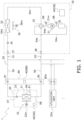
- FIG. 1 is a diagram showing a refrigerant circuit 50 of the refrigeration cycle apparatus 1 according to the present embodiment.
- the refrigeration cycle apparatus 1 mainly includes a heat source unit 30, a plurality of utilization units 20 and 20a, opening degree adjustment units 80 and 80a, and a control unit 40.
- the heat source unit 30 and the plurality of utilization units 20 and 20a are connected by a liquid refrigerant connection pipe 51 and a gas refrigerant connection pipe 52 to constitute the refrigerant circuit 50.
- the heat source unit 30, the plurality of utilization units 20 and 20a, and the opening degree adjustment units 80 and 80a are communicably connected by a communication line (not shown).
- a communication line not shown
- the two utilization units 20 and 20a are shown as an example, but the number of the plurality of utilization units connected to the heat source unit 30 is arbitrary.
- the utilization unit 20 (first utilization unit) will be described below.
- the utilization unit 20 is installed in the target space in a building in which the refrigeration cycle apparatus 1 is installed.
- the utilization unit 20 is a ceiling embedded unit, a ceiling pendant unit, a floor-standing unit, or the like.
- the utilization unit 20 mainly includes a utilization heat exchanger 21, a utilization fan 22, a utilization expansion valve 23 (second opening degree adjustment valve), a utilization control unit 29, a refrigerant sensor 61 (first sensor), and a saturation temperature sensor 64.
- the utilization unit 20 also includes a liquid refrigerant pipe 57 that connects a liquid side end of the utilization heat exchanger 21 and a liquid refrigerant connection pipe 55 which is a branch of the liquid refrigerant connection pipe 51 toward the utilization unit 20.
- the utilization unit 20 includes a gas refrigerant pipe 58 that connects a gas side end of the utilization heat exchanger 21 and a gas refrigerant connection pipe 56 which is a branch of the gas refrigerant connection pipe 52 toward the utilization unit 20.
- the liquid refrigerant pipe 57 and the gas refrigerant pipe 58 are provided in the utilization unit 20.
- the utilization heat exchanger 21 causes heat exchange between a refrigerant flowing in the utilization heat exchanger 21 and air in the target space.
- the utilization heat exchanger 21 is, for example, a fin-and-tube heat exchanger including a plurality of heat transfer fins and a plurality of heat transfer tubes.
- the utilization fan 22 supplies air in the target space to the utilization heat exchanger 21.
- Examples of the utilization fan 22 include a centrifugal fan such as a turbo fan and a sirocco fan. As shown in FIG. 1 , the utilization fan 22 is driven by a utilization fan motor 22m.
- the utilization fan motor 22m has the number of rotations controllable by an inverter.
- the utilization expansion valve 23 is a mechanism for controlling pressure and a flow rate of the refrigerant flowing in the liquid refrigerant pipe 57.
- the utilization expansion valve 23 is provided in the liquid refrigerant pipe 57.
- the utilization expansion valve 23 is a motor valve having an adjustable opening degree.
- the refrigerant sensor 61 detects leakage of the refrigerant.
- the refrigerant sensor 61 is provided, for example, near the utilization heat exchanger 21.
- the saturation temperature sensor 64 measures a temperature of the refrigerant flowing through the utilization heat exchanger 21.
- the saturation temperature sensor 64 measures an evaporation temperature of the refrigerant flowing through the utilization heat exchanger 21 during a cooling operation.
- the saturation temperature sensor 64 measures a condensation temperature of the refrigerant flowing through the utilization heat exchanger 21 during a heating operation.
- the saturation temperature sensor 64 is provided in the utilization heat exchanger 21.
- the utilization control unit 29 is communicably connected to various devices of the utilization unit 20 including the utilization expansion valve 23, the utilization fan motor 22m, the refrigerant sensor 61, and the saturation temperature sensor 64.
- the utilization control unit 29 includes a control arithmetic device and a storage device.
- the control arithmetic device include a processor such as a CPU and a GPU.
- the storage device include a storage medium such as a RAM, a ROM, and a flash memory.
- the control arithmetic device reads a program stored in the storage device and executes predetermined arithmetic processing in accordance with the program, to control behavior of various devices included in the utilization unit 20.
- the control arithmetic device is capable of writing an arithmetic result to the storage device, and reading information stored in the storage device, in accordance with the program.
- the utilization control unit 29 is configured to be able to receive various signals transmitted from an operation remote controller (not shown). Examples of the various signals include signals for commanding a start or a stop of operation, and signals related to various settings. Examples of the signals related to the various settings include a signal relevant to a set temperature or a set air volume.
- the utilization control unit 29 exchanges control signals, measurement signals, signals related to various settings, and the like with the heat source control unit 39 of the heat source unit 30 and the opening degree control unit 89 of the opening degree adjustment unit 80 via a communication line.
- the utilization control unit 29, the heat source control unit 39, and the opening degree control unit 89 cooperate with each other to function as the control unit 40.
- the heat source unit 30 is installed on a rooftop of a building where the refrigeration cycle apparatus 1 is installed, for example.
- the heat source unit 30 mainly includes a compressor 31, a flow path switching valve 32, a heat source heat exchanger 33, a heat source expansion valve 34, an accumulator 35, a heat source fan 36, a liquid shutoff valve 37, a gas shutoff valve 38, a heat source control unit 39, a suction pressure sensor 68, and a discharge pressure sensor 69.
- the heat source unit 30 includes a suction pipe 54a, a discharge pipe 54b, gas refrigerant pipes 54c and 54e, and a liquid refrigerant pipe 54d.
- the suction pipe 54a connects the flow path switching valve 32 and a suction side of the compressor 31.
- the suction pipe 54a is provided with the accumulator 35.
- the discharge pipe 54b connects a discharge side of the compressor 31 and the flow path switching valve 32.
- the gas refrigerant pipe 54c connects the flow path switching valve 32 and a gas side end of the heat source heat exchanger 33.
- the liquid refrigerant pipe 54d connects a liquid side end of the heat source heat exchanger 33 and the liquid refrigerant connection pipe 51.
- the liquid refrigerant pipe 54d is provided with the heat source expansion valve 34.
- the liquid shutoff valve 37 is provided at a connection portion between the liquid refrigerant pipe 54d and the liquid refrigerant connection pipe 51.
- the gas refrigerant pipe 54e connects the flow path switching valve 32 and the gas refrigerant connection pipe 52.
- the gas shutoff valve 38 is provided at a connection portion between the gas refrigerant pipe 54e and the gas refrigerant connection pipe 52.
- the liquid shutoff valve 37 and the gas shutoff valve 38 are openable and closable manually.
- the compressor 31 sucks a low-pressure refrigerant from the suction pipe 54a, compresses the refrigerant by a compression mechanism (not shown), and discharges the compressed refrigerant to the discharge pipe 54b.
- the compressor 31 is, for example, a displacement compressor of a rotary type or a scroll type.
- the compressor 31 includes the compression mechanism driven by a compressor motor 31m.
- the compressor motor 31m has the number of rotations controllable by an inverter.
- the flow path switching valve 32 is a mechanism that switches a refrigerant flow path between a first state and a second state.
- the flow path switching valve 32 causes the suction pipe 54a to communicate with the gas refrigerant pipe 54e and causes the discharge pipe 54b to communicate with the gas refrigerant pipe 54c as indicated by a solid line in the flow path switching valve 32 in FIG. 1 .
- the flow path switching valve 32 causes the suction pipe 54a to communicate with the gas refrigerant pipe 54c and causes the discharge pipe 54b to communicate with the gas refrigerant pipe 54e as indicated by a broken line in the flow path switching valve 32 in FIG. 1 .
- the flow path switching valve 32 brings the refrigerant flow path into the first state.
- the refrigerant discharged from the compressor 31 flows in the refrigerant circuit 50 through the heat source heat exchanger 33, the heat source expansion valve 34, the utilization expansion valve 23, and the utilization heat exchanger 21 in the mentioned order, and returns to the compressor 31.
- the heat source heat exchanger 33 functions as a condenser and the utilization heat exchanger 21 functions as an evaporator.
- the flow path switching valve 32 brings the refrigerant flow path into the second state.
- the refrigerant discharged from the compressor 31 flows in the refrigerant circuit 50 through the utilization heat exchanger 21, the utilization expansion valve 23, the heat source expansion valve 34, and the heat source heat exchanger 33 in the mentioned order, and returns to the compressor 31.
- the heat source heat exchanger 33 functions as an evaporator and the utilization heat exchanger 21 functions as a condenser.
- the heat source heat exchanger 33 causes heat exchange between the refrigerant flowing through the heat source heat exchanger 33 and air around the heat source unit 30.
- the heat source heat exchanger 33 is, for example, a fin-and-tube heat exchanger including a plurality of heat transfer fins and a plurality of heat transfer tubes.
- the heat source expansion valve 34 is a mechanism for controlling pressure and a flow rate of the refrigerant flowing in the liquid refrigerant pipe 54d. As shown in FIG. 1 , the heat source expansion valve 34 is provided in the liquid refrigerant pipe 54d.
- the heat source expansion valve 34 is a motor valve having an adjustable opening degree.
- the accumulator 35 is a container having a gas-liquid separation function of separating an incoming refrigerant into a gas refrigerant and a liquid refrigerant. As shown in FIG. 1 , the accumulator 35 is disposed in the suction pipe 54a. The refrigerant flowing into the accumulator 35 is separated into a gas refrigerant and a liquid refrigerant, and the gas refrigerant collecting in an upper space flows into the compressor 31.
- the heat source fan 36 supplies air around the heat source unit 30 to the heat source heat exchanger 33.
- the heat source fan 36 is, for example, an axial fan such as a propeller fan. As shown in FIG. 1 , the heat source fan 36 is driven by a heat source fan motor 36m.
- the heat source fan motor 36m has the number of rotations controllable by an inverter.
- the suction pressure sensor 68 is a sensor that measures a suction pressure of the compressor 31.
- the suction pressure sensor 68 is provided in the suction pipe 54a.
- the suction pressure is a refrigerant pressure corresponding to an evaporation pressure during the cooling operation.
- the discharge pressure sensor 69 is a sensor that measures a discharge pressure of the compressor 31.
- the discharge pressure sensor 69 is provided in the discharge pipe 54b.
- the discharge pressure is a refrigerant pressure corresponding to a condensation pressure during the heating operation.
- the heat source control unit 39 is communicably connected to various devices included in the heat source unit 30, including the compressor motor 31m, the flow path switching valve 32, the heat source expansion valve 34, the heat source fan motor 36m, the suction pressure sensor 68, and the discharge pressure sensor 69.
- the heat source control unit 39 includes a control arithmetic device and a storage device.
- the control arithmetic device include a processor such as a CPU and a GPU.
- the storage device include a storage medium such as a RAM, a ROM, and a flash memory.
- the control arithmetic device reads a program stored in the storage device and executes predetermined arithmetic processing in accordance with the program, to control behavior of various devices included in the heat source unit 30.
- the control arithmetic device is capable of writing an arithmetic result to the storage device, and reading information stored in the storage device, in accordance with the program.
- the heat source control unit 39 exchanges control signals, measurement signals, signals related to various settings, and the like with the utilization control unit 29 of the utilization unit 20 and the opening degree control unit 89 of the opening degree adjustment unit 80 via a communication line.
- the heat source control unit 39, the utilization control unit 29, and the opening degree control unit 89 cooperate with each other to function as the control unit 40.
- the opening degree adjustment unit 80 Since the structures of the opening degree adjustment units 80 and 80a are basically similar, the opening degree adjustment unit 80 will be described below.
- the opening degree adjustment unit 80 is provided for the utilization unit 20.
- the opening degree adjustment unit 80 includes a liquid opening degree adjustment valve 81, a gas opening degree adjustment valve 82, and the opening degree control unit 89.
- the liquid opening degree adjustment valve 81 is provided in the liquid refrigerant connection pipe 55 connected to the utilization unit 20.
- the liquid opening degree adjustment valve 81 is provided in the liquid refrigerant connection pipe 55 on a liquid side connected to the utilization unit 20.
- the gas opening degree adjustment valve 82 is provided in the gas refrigerant connection pipe 56 connected to the utilization unit 20.
- the gas opening degree adjustment valve 82 (first opening degree adjustment valve) is provided in the gas refrigerant connection pipe 56 (first refrigerant pipe) on a gas side connected to the utilization unit 20.
- the liquid opening degree adjustment valve 81 and the gas opening degree adjustment valve 82 are motor valves having adjustable opening degrees. Furthermore, when the liquid opening degree adjustment valve 81 is fully closed, the liquid opening degree adjustment valve 81 functions as a shutoff valve that shuts off the refrigerant flowing through the liquid refrigerant connection pipe 55. When the gas opening degree adjustment valve 82 is fully closed, the gas opening degree adjustment valve 82 functions as a shutoff valve that shuts off the refrigerant flowing through the gas refrigerant connection pipe 56.
- the opening degree control unit 89 is communicably connected to various devices of the opening degree adjustment unit 80 including the liquid opening degree adjustment valve 81 and the gas opening degree adjustment valve 82.
- the opening degree control unit 89 includes a control arithmetic device and a storage device.
- the control arithmetic device include a processor such as a CPU and a GPU.
- the storage device include a storage medium such as a RAM, a ROM, and a flash memory.
- the control arithmetic device reads a program stored in the storage device and executes predetermined arithmetic processing in accordance with the program, to control behavior of various devices included in the heat source unit 30.
- the control arithmetic device is capable of writing an arithmetic result to the storage device, and reading information stored in the storage device, in accordance with the program.
- the opening degree control unit 89 exchanges control signals, measurement signals, signals related to various settings, and the like with the utilization control unit 29 of the utilization unit 20 and the heat source control unit 39 of the heat source unit 30 via a communication line.
- the opening degree control unit 89, the utilization control unit 29, and the heat source control unit 39 cooperate with each other to function as the control unit 40.
- the control unit 40 includes the utilization control unit 29, the heat source control unit 39, and the opening degree control unit 89.
- the control unit 40 controls the entire operation of the refrigeration cycle apparatus 1 by causing each control arithmetic device of the utilization control unit 29, the heat source control unit 39, and the opening degree control unit 89 to execute the program stored in each storage device.
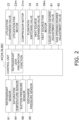
- FIG. 2 is a control block diagram of the refrigeration cycle apparatus 1 according to the present embodiment.
- the control unit 40 is communicably connected to the utilization expansion valve 23, the utilization fan motor 22m, the refrigerant sensor 61, the saturation temperature sensor 64, the compressor motor 31m, the flow path switching valve 32, the heat source expansion valve 34, the heat source fan motor 36m, the suction pressure sensor 68, the discharge pressure sensor 69, the liquid opening degree adjustment valve 81, and the gas opening degree adjustment valve 82.
- the control unit 40 controls behavior of various devices included in the refrigeration cycle apparatus 1 on the basis of control signals received from an operation remote controller via the utilization unit 20, measurement signals of various sensors, and the like.
- the control unit 40 mainly performs the cooling operation and the heating operation.
- the control unit 40 mainly has a refrigerant leak prevention function.
- control unit 40 when receiving an instruction to perform the cooling operation from the operation remote controller via the utilization unit 20, the control unit 40 switches the flow path switching valve 32 to the first state.
- the control unit 40 fully opens the heat source expansion valve 34, and controls the liquid opening degree adjustment valve 81, the gas opening degree adjustment valve 82, the compressor motor 31m, the utilization expansion valve 23, and the like so that the evaporation temperature as a measurement value of the saturation temperature sensor 64 becomes a target evaporation temperature.
- the control unit 40 controls the gas opening degree adjustment valve 82 to adjust the evaporation temperature of the refrigerant flowing through the utilization heat exchanger 21.
- the control unit 40 increases the evaporation temperature of the refrigerant flowing through the utilization heat exchanger 21 by decreasing the opening degree of the gas opening degree adjustment valve 82.
- the target evaporation temperature is set in accordance with a set temperature received from the operation remote controller, for example.
- the refrigerant flows through the refrigerant circuit 50 during the cooling operation as follows.
- a low-pressure gas refrigerant is sucked into the compressor 31 and is compressed by the compressor 31 into a high-pressure gas refrigerant.
- the high-pressure gas refrigerant is sent to the heat source heat exchanger 33 via the flow path switching valve 32, exchanges heat with air around the heat source unit 30 supplied by the heat source fan 36, and is condensed into a high-pressure liquid refrigerant.
- the high-pressure liquid refrigerant flows through the liquid refrigerant pipe 54d and passes through the heat source expansion valve 34.
- the high-pressure liquid refrigerant sent to the utilization unit 20 is decompressed at the utilization expansion valve 23 to have pressure close to the suction pressure of the compressor 31 and come into a refrigerant in a gas-liquid two-phase state, and is sent to the utilization heat exchanger 21.
- the refrigerant in the gas-liquid two-phase state exchanges heat, in the utilization heat exchanger 21, with air in the target space supplied into the utilization heat exchanger 21 by the utilization fan 22 to be evaporated into a low-pressure gas refrigerant.
- the low-pressure gas refrigerant is sent to the heat source unit 30 via the gas refrigerant connection pipe 52, and flows into the accumulator 35 via the flow path switching valve 32.
- the low-pressure gas refrigerant having flowed into the accumulator 35 is sucked into the compressor 31 again.
- Air supplied to the utilization heat exchanger 21 is decreased in temperature through heat exchange with the refrigerant flowing in the utilization heat exchanger 21. Accordingly, the air cooled in the utilization heat exchanger 21 blows out into the target space.
- control unit 40 switches the flow path switching valve 32 to the second state.
- the control unit 40 controls the liquid opening degree adjustment valve 81, the gas opening degree adjustment valve 82, the compressor motor 31m, the utilization expansion valve 23, and the like so that the condensation temperature as a measurement value of the saturation temperature sensor 64 becomes a target condensation temperature.
- the control unit 40 controls the gas opening degree adjustment valve 82 to adjust the condensation temperature of the refrigerant flowing through the utilization heat exchanger 21.
- the control unit 40 decreases the condensation temperature of the refrigerant flowing through the utilization heat exchanger 21 by decreasing the opening degree of the gas opening degree adjustment valve 82.
- the target condensation temperature is set in accordance with a set temperature received from the operation remote controller, for example.
- the control unit 40 controls the opening degree of the heat source expansion valve 34 such that the refrigerant flowing into the heat source heat exchanger 33 is decompressed to have pressure allowing evaporation in the heat source heat exchanger 33.
- a low-pressure gas refrigerant is sucked into the compressor 31 and is compressed by the compressor 31 into a high-pressure gas refrigerant.
- the high-pressure gas refrigerant is sent to the utilization heat exchanger 21 via the flow path switching valve 32, exchanges heat with the air in the target space supplied to the utilization heat exchanger 21 by the utilization fan 22, and is condensed into a high-pressure liquid refrigerant.
- Air supplied to the utilization heat exchanger 21 is increased in temperature through heat exchange with the refrigerant flowing in the utilization heat exchanger 21. Accordingly, the air heated in the utilization heat exchanger 21 blows out into the target space.
- the high-pressure liquid refrigerant having passed through the utilization heat exchanger 21 is decompressed in the utilization expansion valve 23.
- the decompressed liquid refrigerant is sent to the heat source unit 30 via the liquid refrigerant connection pipe 51, and flows into the liquid refrigerant pipe 54d.
- the refrigerant flowing through the liquid refrigerant pipe 54d is decompressed in the heat source expansion valve 34 to have pressure close to the suction pressure of the compressor 31 and come into a refrigerant in the gas-liquid two-phase state, and flows into the heat source heat exchanger 33.
- the low-pressure refrigerant in the gas-liquid two-phase state having flowed into the heat source heat exchanger 33 exchanges heat with air around the heat source unit 30 supplied by the heat source fan 36 to be evaporated into a low-pressure gas refrigerant.
- the low-pressure gas refrigerant flows into the accumulator 35 via the flow path switching valve 32.
- the low-pressure gas refrigerant having flowed into the accumulator 35 is sucked into the compressor 31 again.
- the control unit 40 When the refrigerant sensor 61 detects leakage of the refrigerant, the control unit 40 fully closes the liquid opening degree adjustment valve 81 to block the refrigerant leaking from the utilization unit 20 through the liquid refrigerant connection pipe 55. When the refrigerant sensor 61 detects leakage of the refrigerant, the control unit 40 fully closes the gas opening degree adjustment valve 82 to block the refrigerant leaking from the utilization unit 20 through the gas refrigerant connection pipe 56. The control unit 40 may further fully close the utilization expansion valve 23.
- the control unit 40 controls the compressor 31 on the basis of a pressure fluctuation of the refrigerant flowing in the refrigerant circuit 50 caused by fully closing the gas opening degree adjustment valve 82. For example, when a measurement value of the suction pressure sensor 68 increases by fully closing the gas opening degree adjustment valve 82, the control unit 40 decreases the number of rotations of the compressor motor 31m.
- the refrigeration cycle apparatus 1 includes the heat source unit 30, the plurality of utilization units 20 and 20a, the gas opening degree adjustment valve 82, and the control unit 40.
- the heat source unit 30 includes the compressor 31.
- the plurality of utilization units 20 and 20a constitutes the refrigerant circuit 50 together with the heat source unit 30.
- the plurality of utilization units 20 and 20a includes the utilization unit 20.
- the gas opening degree adjustment valve 82 is provided for the utilization unit 20.
- the utilization unit 20 includes the refrigerant sensor 61.
- the refrigerant sensor 61 detects leakage of the refrigerant.
- the control unit 40 controls the gas opening degree adjustment valve 82 to adjust the evaporation temperature or the condensation temperature in the utilization unit 20. When the refrigerant sensor 61 detects leakage of the refrigerant, the control unit 40 fully closes the gas opening degree adjustment valve 82 to block the refrigerant leaking from the utilization unit 20.
- the control unit 40 When the refrigerant sensor 61 detects leakage of the refrigerant in the refrigeration cycle apparatus 1, the control unit 40 fully closes the gas opening degree adjustment valve 82 to block the refrigerant leaking from the utilization unit 20.
- the refrigeration cycle apparatus 1 can simplify the structure of the refrigeration cycle apparatus 1 by using the gas opening degree adjustment valve 82 as a shutoff valve that shuts off the refrigerant leaking from the utilization unit 20.
- the gas opening degree adjustment valve 82 is provided in the gas refrigerant connection pipe 56 on the gas side connected to the utilization unit 20.
- the control unit 40 fully closes the gas opening degree adjustment valve 82 to block the refrigerant leaking from the utilization unit 20 through the gas refrigerant connection pipe 56.
- control unit 40 controls the gas opening degree adjustment valve 82 such that the evaporation temperature or the condensation temperature in the utilization unit 20 becomes the target evaporation temperature or the target condensation temperature.
- the control unit 40 controls the compressor 31 on the basis of a pressure fluctuation of the refrigerant flowing in the refrigerant circuit 50 caused by fully closing the gas opening degree adjustment valve 82.
- the refrigeration cycle apparatus 1 can prevent the other utilization units from being damaged caused by increasing the pressure of the refrigerant flowing in the other utilization units as a result of fully closing the gas opening degree adjustment valve 82.
- the control unit 40 controls the compressor 31 on the basis of a pressure fluctuation of the refrigerant flowing in the refrigerant circuit 50 caused by fully closing the gas opening degree adjustment valve 82.
- the control unit 40 may control the compressor 31 on the basis of the state of the utilization unit 20 after fully closing the gas opening degree adjustment valve 82.
- the state of the utilization unit 20 includes the capacity of the utilization unit 20 or the opening degree of the gas opening degree adjustment valve 82.
- the control unit 40 fully closes the gas opening degree adjustment valve 82 and then decreases the number of rotations of the compressor motor 31m.
- the control unit 40 fully closing the gas opening degree adjustment valve 82. Therefore, when the opening degree of the gas opening degree adjustment valve 82 before being fully closed is relatively large, the control unit 40 fully closes the gas opening degree adjustment valve 82 and then decreases the number of rotations of the compressor motor 31m.
- the state of the utilization unit 20 may include the opening degree of the utilization expansion valve 23.
- the opening degree of the utilization expansion valve 23 before the gas opening degree adjustment valve 82 is fully closed is relatively large, there is a high possibility that the pressure of the refrigerant flowing in the other utilization units increases by the control unit 40 fully closing the gas opening degree adjustment valve 82. Therefore, when the opening degree of the utilization expansion valve 23 before the gas opening degree adjustment valve 82 is fully closed is relatively large, the control unit 40 fully closes the gas opening degree adjustment valve 82 and then decreases the number of rotations of the compressor motor 31m.
- the refrigeration cycle apparatus 1 can prevent the other utilization units from being damaged caused by increasing the pressure of the refrigerant flowing in the other utilization units as a result of fully closing the gas opening degree adjustment valve 82.
- control unit 40 may control the compressor 31 on the basis of the state of the utilization unit 20 and then fully close the gas opening degree adjustment valve 82.
- the opening degree adjustment unit 80 may be provided for each of the plurality of utilization units connected to the heat source unit 30, or may be provided for some of the plurality of utilization units.
- the refrigeration cycle apparatus 1 may be a multi-type air conditioning system for buildings in which the plurality of utilization units connected to the heat source unit 30 can independently perform the cooling operation and the heating operation.
- FIG. 3 is a diagram showing the refrigerant circuit 50 of the refrigeration cycle apparatus 1 according to the present embodiment.
- an opening degree adjustment unit 801 in the present embodiment does not include the liquid opening degree adjustment valve 81 unlike the opening degree adjustment unit 80 in the first embodiment.
- the utilization expansion valve 23 also functions as the liquid opening degree adjustment valve 81.
- the refrigeration cycle apparatus 1 can simplify the structure of the refrigeration cycle apparatus 1 by using the gas opening degree adjustment valve 82 as a shutoff valve that shuts off the refrigerant leaking from the utilization unit 20.
- the opening degree adjustment unit 801 may be provided for each of the plurality of utilization units connected to the heat source unit 30, or may be provided for some of the plurality of utilization units. As illustrated in FIG. 3 , different types of opening degree adjustment units may be provided for the plurality of utilization units, for example, the opening degree adjustment unit 801 may be provided for the utilization unit 20, and the opening degree adjustment unit 80a may be provided for the utilization unit 20a.
- Patent Literature 1 JP 2008-281304 A
Landscapes
- Engineering & Computer Science (AREA)
- Mechanical Engineering (AREA)
- General Engineering & Computer Science (AREA)
- Physics & Mathematics (AREA)
- Thermal Sciences (AREA)
- Chemical & Material Sciences (AREA)
- Combustion & Propulsion (AREA)
- Air Conditioning Control Device (AREA)
Abstract
Description
- The present disclosure relates to a refrigeration cycle apparatus.
- As disclosed in Patent Literature 1 (
JP 2008-281304 A - In preparation for leakage of a refrigerant in the utilization unit, it is desirable to provide the utilization unit with a shutoff valve that shuts off leakage of the refrigerant. However, when the shutoff valve is provided separately from the opening degree adjustment valve, there is a problem that the structure of the refrigeration cycle apparatus becomes complicated.
- A refrigeration cycle apparatus according to a first aspect includes a heat source unit, a plurality of utilization units, a first opening degree adjustment valve, and a control unit. The heat source unit includes a compressor. The plurality of utilization units constitutes a refrigerant circuit together with the heat source unit. The plurality of utilization units includes a first utilization unit. The first opening degree adjustment valve is provided for the first utilization unit. The first utilization unit includes a first sensor. The first sensor detects leakage of a refrigerant. The control unit controls the first opening degree adjustment valve to adjust an evaporation temperature or a condensation temperature in the first utilization unit. When the first sensor detects leakage of the refrigerant, the control unit fully closes the first opening degree adjustment valve to block the refrigerant leaking from the first utilization unit.
- When the first sensor detects leakage of the refrigerant in the refrigeration cycle apparatus according to the first aspect, the control unit fully closes the first opening degree adjustment valve to block the refrigerant leaking from the first utilization unit. As a result, the refrigeration cycle apparatus can simplify the structure of the refrigeration cycle apparatus by using the first opening degree adjustment valve as a shutoff valve that shuts off the refrigerant leaking from the first utilization unit.
- A refrigeration cycle apparatus according to a second aspect is the refrigeration cycle apparatus according to the first aspect, in which the first opening degree adjustment valve is provided in a first refrigerant pipe on a gas side connected to the first utilization unit. When the first sensor detects leakage of the refrigerant, the control unit fully closes the first opening degree adjustment valve to block the refrigerant leaking from the first utilization unit through the first refrigerant pipe.
- A refrigeration cycle apparatus according to a third aspect is the refrigeration cycle apparatus according to the first or second aspect, in which the control unit controls the first opening degree adjustment valve such that the evaporation temperature or the condensation temperature in the first utilization unit becomes a target evaporation temperature or a target condensation temperature.
- A refrigeration cycle apparatus according to a fourth aspect is the refrigeration cycle apparatus according to any of the first to third aspects, in which when the first sensor detects leakage of the refrigerant, the control unit controls the compressor on the basis of a pressure fluctuation of the refrigerant flowing in the refrigerant circuit, the pressure fluctuation being caused by fully closing the first opening degree adjustment valve.
- By such a configuration, the refrigeration cycle apparatus according to the fourth aspect can prevent the other utilization units from being damaged caused by increasing the pressure of the refrigerant flowing in the other utilization units.
- A refrigeration cycle apparatus according to a fifth aspect is the refrigeration cycle apparatus according to any of the first to third aspects, in which when the first sensor detects leakage of the refrigerant, the control unit controls the compressor on the basis of a state of the first utilization unit.
- By such a configuration, the refrigeration cycle apparatus according to the fifth aspect can prevent the other utilization units from being damaged caused by increasing the pressure of the refrigerant flowing in the other utilization units.
- A refrigeration cycle apparatus according to a sixth aspect is the refrigeration cycle apparatus according to the fifth aspect, in which the state of the first utilization unit includes a capacity of the first utilization unit or an opening degree of the first opening degree adjustment valve.
- A refrigeration cycle apparatus according to a seventh aspect is the refrigeration cycle apparatus according to the fifth aspect, in which the first utilization unit includes a second opening degree adjustment valve inside the first utilization unit. The state of the first utilization unit includes an opening degree of the second opening degree adjustment valve.
-
-
FIG. 1 is a diagram showing a refrigerant circuit of a refrigeration cycle apparatus according to a first embodiment. -
FIG. 2 is a control block diagram of the refrigeration cycle apparatus according to the first embodiment. -
FIG. 3 is a diagram showing a refrigerant circuit of a refrigeration cycle apparatus according to a second embodiment. - A
refrigeration cycle apparatus 1 constitutes a vapor compression refrigeration cycle and performs air conditioning of a target space. In the present embodiment, therefrigeration cycle apparatus 1 is a so-called multi-type air conditioning system for buildings.FIG. 1 is a diagram showing arefrigerant circuit 50 of therefrigeration cycle apparatus 1 according to the present embodiment. As shown inFIG. 1 , therefrigeration cycle apparatus 1 mainly includes aheat source unit 30, a plurality ofutilization units degree adjustment units control unit 40. Theheat source unit 30 and the plurality ofutilization units refrigerant connection pipe 51 and a gasrefrigerant connection pipe 52 to constitute therefrigerant circuit 50. Theheat source unit 30, the plurality ofutilization units degree adjustment units FIG. 1 , the twoutilization units heat source unit 30 is arbitrary. - Since the structures of the
utilization units - The
utilization unit 20 is installed in the target space in a building in which therefrigeration cycle apparatus 1 is installed. Theutilization unit 20 is a ceiling embedded unit, a ceiling pendant unit, a floor-standing unit, or the like. As shown inFIG. 1 , theutilization unit 20 mainly includes autilization heat exchanger 21, autilization fan 22, a utilization expansion valve 23 (second opening degree adjustment valve), autilization control unit 29, a refrigerant sensor 61 (first sensor), and asaturation temperature sensor 64. Theutilization unit 20 also includes aliquid refrigerant pipe 57 that connects a liquid side end of theutilization heat exchanger 21 and a liquidrefrigerant connection pipe 55 which is a branch of the liquidrefrigerant connection pipe 51 toward theutilization unit 20. Theutilization unit 20 includes agas refrigerant pipe 58 that connects a gas side end of theutilization heat exchanger 21 and a gasrefrigerant connection pipe 56 which is a branch of the gasrefrigerant connection pipe 52 toward theutilization unit 20. Theliquid refrigerant pipe 57 and thegas refrigerant pipe 58 are provided in theutilization unit 20. - The
utilization heat exchanger 21 causes heat exchange between a refrigerant flowing in theutilization heat exchanger 21 and air in the target space. Theutilization heat exchanger 21 is, for example, a fin-and-tube heat exchanger including a plurality of heat transfer fins and a plurality of heat transfer tubes. - The
utilization fan 22 supplies air in the target space to theutilization heat exchanger 21. Examples of theutilization fan 22 include a centrifugal fan such as a turbo fan and a sirocco fan. As shown inFIG. 1 , theutilization fan 22 is driven by autilization fan motor 22m. Theutilization fan motor 22m has the number of rotations controllable by an inverter. - The
utilization expansion valve 23 is a mechanism for controlling pressure and a flow rate of the refrigerant flowing in theliquid refrigerant pipe 57. Theutilization expansion valve 23 is provided in theliquid refrigerant pipe 57. Theutilization expansion valve 23 is a motor valve having an adjustable opening degree. - The
refrigerant sensor 61 detects leakage of the refrigerant. Therefrigerant sensor 61 is provided, for example, near theutilization heat exchanger 21. - The
saturation temperature sensor 64 measures a temperature of the refrigerant flowing through theutilization heat exchanger 21. Thesaturation temperature sensor 64 measures an evaporation temperature of the refrigerant flowing through theutilization heat exchanger 21 during a cooling operation. Thesaturation temperature sensor 64 measures a condensation temperature of the refrigerant flowing through theutilization heat exchanger 21 during a heating operation. Thesaturation temperature sensor 64 is provided in theutilization heat exchanger 21. - The
utilization control unit 29 is communicably connected to various devices of theutilization unit 20 including theutilization expansion valve 23, theutilization fan motor 22m, therefrigerant sensor 61, and thesaturation temperature sensor 64. - The
utilization control unit 29 includes a control arithmetic device and a storage device. Examples of the control arithmetic device include a processor such as a CPU and a GPU. Examples of the storage device include a storage medium such as a RAM, a ROM, and a flash memory. The control arithmetic device reads a program stored in the storage device and executes predetermined arithmetic processing in accordance with the program, to control behavior of various devices included in theutilization unit 20. The control arithmetic device is capable of writing an arithmetic result to the storage device, and reading information stored in the storage device, in accordance with the program. - The
utilization control unit 29 is configured to be able to receive various signals transmitted from an operation remote controller (not shown). Examples of the various signals include signals for commanding a start or a stop of operation, and signals related to various settings. Examples of the signals related to the various settings include a signal relevant to a set temperature or a set air volume. - The
utilization control unit 29 exchanges control signals, measurement signals, signals related to various settings, and the like with the heatsource control unit 39 of theheat source unit 30 and the openingdegree control unit 89 of the openingdegree adjustment unit 80 via a communication line. Theutilization control unit 29, the heatsource control unit 39, and the openingdegree control unit 89 cooperate with each other to function as thecontrol unit 40. - The
heat source unit 30 is installed on a rooftop of a building where therefrigeration cycle apparatus 1 is installed, for example. As illustrated inFIG. 1 , theheat source unit 30 mainly includes acompressor 31, a flowpath switching valve 32, a heatsource heat exchanger 33, a heatsource expansion valve 34, anaccumulator 35, aheat source fan 36, aliquid shutoff valve 37, agas shutoff valve 38, a heatsource control unit 39, asuction pressure sensor 68, and adischarge pressure sensor 69. In addition, theheat source unit 30 includes asuction pipe 54a, adischarge pipe 54b,gas refrigerant pipes refrigerant pipe 54d. - The
suction pipe 54a connects the flowpath switching valve 32 and a suction side of thecompressor 31. Thesuction pipe 54a is provided with theaccumulator 35. Thedischarge pipe 54b connects a discharge side of thecompressor 31 and the flowpath switching valve 32. Thegas refrigerant pipe 54c connects the flowpath switching valve 32 and a gas side end of the heatsource heat exchanger 33. The liquidrefrigerant pipe 54d connects a liquid side end of the heatsource heat exchanger 33 and the liquidrefrigerant connection pipe 51. The liquidrefrigerant pipe 54d is provided with the heatsource expansion valve 34. Theliquid shutoff valve 37 is provided at a connection portion between the liquidrefrigerant pipe 54d and the liquidrefrigerant connection pipe 51. Thegas refrigerant pipe 54e connects the flowpath switching valve 32 and the gasrefrigerant connection pipe 52. Thegas shutoff valve 38 is provided at a connection portion between thegas refrigerant pipe 54e and the gasrefrigerant connection pipe 52. Theliquid shutoff valve 37 and thegas shutoff valve 38 are openable and closable manually. - As shown in
FIG. 1 , thecompressor 31 sucks a low-pressure refrigerant from thesuction pipe 54a, compresses the refrigerant by a compression mechanism (not shown), and discharges the compressed refrigerant to thedischarge pipe 54b. - The
compressor 31 is, for example, a displacement compressor of a rotary type or a scroll type. Thecompressor 31 includes the compression mechanism driven by acompressor motor 31m. Thecompressor motor 31m has the number of rotations controllable by an inverter. - The flow
path switching valve 32 is a mechanism that switches a refrigerant flow path between a first state and a second state. In the first state, the flowpath switching valve 32 causes thesuction pipe 54a to communicate with thegas refrigerant pipe 54e and causes thedischarge pipe 54b to communicate with thegas refrigerant pipe 54c as indicated by a solid line in the flowpath switching valve 32 inFIG. 1 . In the second state, the flowpath switching valve 32 causes thesuction pipe 54a to communicate with thegas refrigerant pipe 54c and causes thedischarge pipe 54b to communicate with thegas refrigerant pipe 54e as indicated by a broken line in the flowpath switching valve 32 inFIG. 1 . - During the cooling operation, the flow
path switching valve 32 brings the refrigerant flow path into the first state. At this time, the refrigerant discharged from thecompressor 31 flows in therefrigerant circuit 50 through the heatsource heat exchanger 33, the heatsource expansion valve 34, theutilization expansion valve 23, and theutilization heat exchanger 21 in the mentioned order, and returns to thecompressor 31. In the first state, the heatsource heat exchanger 33 functions as a condenser and theutilization heat exchanger 21 functions as an evaporator. - During the heating operation, the flow
path switching valve 32 brings the refrigerant flow path into the second state. At this time, the refrigerant discharged from thecompressor 31 flows in therefrigerant circuit 50 through theutilization heat exchanger 21, theutilization expansion valve 23, the heatsource expansion valve 34, and the heatsource heat exchanger 33 in the mentioned order, and returns to thecompressor 31. In the second state, the heatsource heat exchanger 33 functions as an evaporator and theutilization heat exchanger 21 functions as a condenser. - The heat
source heat exchanger 33 causes heat exchange between the refrigerant flowing through the heatsource heat exchanger 33 and air around theheat source unit 30. The heatsource heat exchanger 33 is, for example, a fin-and-tube heat exchanger including a plurality of heat transfer fins and a plurality of heat transfer tubes. - The heat
source expansion valve 34 is a mechanism for controlling pressure and a flow rate of the refrigerant flowing in the liquidrefrigerant pipe 54d. As shown inFIG. 1 , the heatsource expansion valve 34 is provided in the liquidrefrigerant pipe 54d. The heatsource expansion valve 34 is a motor valve having an adjustable opening degree. - The
accumulator 35 is a container having a gas-liquid separation function of separating an incoming refrigerant into a gas refrigerant and a liquid refrigerant. As shown inFIG. 1 , theaccumulator 35 is disposed in thesuction pipe 54a. The refrigerant flowing into theaccumulator 35 is separated into a gas refrigerant and a liquid refrigerant, and the gas refrigerant collecting in an upper space flows into thecompressor 31. - The
heat source fan 36 supplies air around theheat source unit 30 to the heatsource heat exchanger 33. Theheat source fan 36 is, for example, an axial fan such as a propeller fan. As shown inFIG. 1 , theheat source fan 36 is driven by a heatsource fan motor 36m. The heatsource fan motor 36m has the number of rotations controllable by an inverter. - The
suction pressure sensor 68 is a sensor that measures a suction pressure of thecompressor 31. Thesuction pressure sensor 68 is provided in thesuction pipe 54a. The suction pressure is a refrigerant pressure corresponding to an evaporation pressure during the cooling operation. - The
discharge pressure sensor 69 is a sensor that measures a discharge pressure of thecompressor 31. Thedischarge pressure sensor 69 is provided in thedischarge pipe 54b. The discharge pressure is a refrigerant pressure corresponding to a condensation pressure during the heating operation. - The heat
source control unit 39 is communicably connected to various devices included in theheat source unit 30, including thecompressor motor 31m, the flowpath switching valve 32, the heatsource expansion valve 34, the heatsource fan motor 36m, thesuction pressure sensor 68, and thedischarge pressure sensor 69. - The heat
source control unit 39 includes a control arithmetic device and a storage device. Examples of the control arithmetic device include a processor such as a CPU and a GPU. Examples of the storage device include a storage medium such as a RAM, a ROM, and a flash memory. The control arithmetic device reads a program stored in the storage device and executes predetermined arithmetic processing in accordance with the program, to control behavior of various devices included in theheat source unit 30. The control arithmetic device is capable of writing an arithmetic result to the storage device, and reading information stored in the storage device, in accordance with the program. - The heat
source control unit 39 exchanges control signals, measurement signals, signals related to various settings, and the like with theutilization control unit 29 of theutilization unit 20 and the openingdegree control unit 89 of the openingdegree adjustment unit 80 via a communication line. The heatsource control unit 39, theutilization control unit 29, and the openingdegree control unit 89 cooperate with each other to function as thecontrol unit 40. - Since the structures of the opening
degree adjustment units degree adjustment unit 80 will be described below. - As shown in
FIG. 1 , the openingdegree adjustment unit 80 is provided for theutilization unit 20. The openingdegree adjustment unit 80 includes a liquid openingdegree adjustment valve 81, a gas openingdegree adjustment valve 82, and the openingdegree control unit 89. - The liquid opening
degree adjustment valve 81 is provided in the liquidrefrigerant connection pipe 55 connected to theutilization unit 20. In other words, the liquid openingdegree adjustment valve 81 is provided in the liquidrefrigerant connection pipe 55 on a liquid side connected to theutilization unit 20. - The gas opening
degree adjustment valve 82 is provided in the gasrefrigerant connection pipe 56 connected to theutilization unit 20. In other words, the gas opening degree adjustment valve 82 (first opening degree adjustment valve) is provided in the gas refrigerant connection pipe 56 (first refrigerant pipe) on a gas side connected to theutilization unit 20. - The liquid opening
degree adjustment valve 81 and the gas openingdegree adjustment valve 82 are motor valves having adjustable opening degrees. Furthermore, when the liquid openingdegree adjustment valve 81 is fully closed, the liquid openingdegree adjustment valve 81 functions as a shutoff valve that shuts off the refrigerant flowing through the liquidrefrigerant connection pipe 55. When the gas openingdegree adjustment valve 82 is fully closed, the gas openingdegree adjustment valve 82 functions as a shutoff valve that shuts off the refrigerant flowing through the gasrefrigerant connection pipe 56. - The opening
degree control unit 89 is communicably connected to various devices of the openingdegree adjustment unit 80 including the liquid openingdegree adjustment valve 81 and the gas openingdegree adjustment valve 82. - The opening
degree control unit 89 includes a control arithmetic device and a storage device. Examples of the control arithmetic device include a processor such as a CPU and a GPU. Examples of the storage device include a storage medium such as a RAM, a ROM, and a flash memory. The control arithmetic device reads a program stored in the storage device and executes predetermined arithmetic processing in accordance with the program, to control behavior of various devices included in theheat source unit 30. The control arithmetic device is capable of writing an arithmetic result to the storage device, and reading information stored in the storage device, in accordance with the program. - The opening
degree control unit 89 exchanges control signals, measurement signals, signals related to various settings, and the like with theutilization control unit 29 of theutilization unit 20 and the heatsource control unit 39 of theheat source unit 30 via a communication line. The openingdegree control unit 89, theutilization control unit 29, and the heatsource control unit 39 cooperate with each other to function as thecontrol unit 40. - The
control unit 40 includes theutilization control unit 29, the heatsource control unit 39, and the openingdegree control unit 89. Thecontrol unit 40 controls the entire operation of therefrigeration cycle apparatus 1 by causing each control arithmetic device of theutilization control unit 29, the heatsource control unit 39, and the openingdegree control unit 89 to execute the program stored in each storage device. -
FIG. 2 is a control block diagram of therefrigeration cycle apparatus 1 according to the present embodiment. As shown inFig. 2 , thecontrol unit 40 is communicably connected to theutilization expansion valve 23, theutilization fan motor 22m, therefrigerant sensor 61, thesaturation temperature sensor 64, thecompressor motor 31m, the flowpath switching valve 32, the heatsource expansion valve 34, the heatsource fan motor 36m, thesuction pressure sensor 68, thedischarge pressure sensor 69, the liquid openingdegree adjustment valve 81, and the gas openingdegree adjustment valve 82. Thecontrol unit 40 controls behavior of various devices included in therefrigeration cycle apparatus 1 on the basis of control signals received from an operation remote controller via theutilization unit 20, measurement signals of various sensors, and the like. - The
control unit 40 mainly performs the cooling operation and the heating operation. Thecontrol unit 40 mainly has a refrigerant leak prevention function. - For example, when receiving an instruction to perform the cooling operation from the operation remote controller via the
utilization unit 20, thecontrol unit 40 switches the flowpath switching valve 32 to the first state. - Then, the
control unit 40 fully opens the heatsource expansion valve 34, and controls the liquid openingdegree adjustment valve 81, the gas openingdegree adjustment valve 82, thecompressor motor 31m, theutilization expansion valve 23, and the like so that the evaporation temperature as a measurement value of thesaturation temperature sensor 64 becomes a target evaporation temperature. In particular, thecontrol unit 40 controls the gas openingdegree adjustment valve 82 to adjust the evaporation temperature of the refrigerant flowing through theutilization heat exchanger 21. For example, thecontrol unit 40 increases the evaporation temperature of the refrigerant flowing through theutilization heat exchanger 21 by decreasing the opening degree of the gas openingdegree adjustment valve 82. The target evaporation temperature is set in accordance with a set temperature received from the operation remote controller, for example. - When the behavior of various devices is controlled as described above, the refrigerant flows through the
refrigerant circuit 50 during the cooling operation as follows. - When the
compressor 31 is activated, a low-pressure gas refrigerant is sucked into thecompressor 31 and is compressed by thecompressor 31 into a high-pressure gas refrigerant. The high-pressure gas refrigerant is sent to the heatsource heat exchanger 33 via the flowpath switching valve 32, exchanges heat with air around theheat source unit 30 supplied by theheat source fan 36, and is condensed into a high-pressure liquid refrigerant. The high-pressure liquid refrigerant flows through the liquidrefrigerant pipe 54d and passes through the heatsource expansion valve 34. The high-pressure liquid refrigerant sent to theutilization unit 20 is decompressed at theutilization expansion valve 23 to have pressure close to the suction pressure of thecompressor 31 and come into a refrigerant in a gas-liquid two-phase state, and is sent to theutilization heat exchanger 21. The refrigerant in the gas-liquid two-phase state exchanges heat, in theutilization heat exchanger 21, with air in the target space supplied into theutilization heat exchanger 21 by theutilization fan 22 to be evaporated into a low-pressure gas refrigerant. The low-pressure gas refrigerant is sent to theheat source unit 30 via the gasrefrigerant connection pipe 52, and flows into theaccumulator 35 via the flowpath switching valve 32. The low-pressure gas refrigerant having flowed into theaccumulator 35 is sucked into thecompressor 31 again. Air supplied to theutilization heat exchanger 21 is decreased in temperature through heat exchange with the refrigerant flowing in theutilization heat exchanger 21. Accordingly, the air cooled in theutilization heat exchanger 21 blows out into the target space. - For example, when receiving an instruction to perform the heating operation from the operation remote controller via the
utilization unit 20, thecontrol unit 40 switches the flowpath switching valve 32 to the second state. - Then, the
control unit 40 controls the liquid openingdegree adjustment valve 81, the gas openingdegree adjustment valve 82, thecompressor motor 31m, theutilization expansion valve 23, and the like so that the condensation temperature as a measurement value of thesaturation temperature sensor 64 becomes a target condensation temperature. In particular, thecontrol unit 40 controls the gas openingdegree adjustment valve 82 to adjust the condensation temperature of the refrigerant flowing through theutilization heat exchanger 21. For example, thecontrol unit 40 decreases the condensation temperature of the refrigerant flowing through theutilization heat exchanger 21 by decreasing the opening degree of the gas openingdegree adjustment valve 82. The target condensation temperature is set in accordance with a set temperature received from the operation remote controller, for example. Thecontrol unit 40 controls the opening degree of the heatsource expansion valve 34 such that the refrigerant flowing into the heatsource heat exchanger 33 is decompressed to have pressure allowing evaporation in the heatsource heat exchanger 33. - When the
compressor 31 is activated, a low-pressure gas refrigerant is sucked into thecompressor 31 and is compressed by thecompressor 31 into a high-pressure gas refrigerant. The high-pressure gas refrigerant is sent to theutilization heat exchanger 21 via the flowpath switching valve 32, exchanges heat with the air in the target space supplied to theutilization heat exchanger 21 by theutilization fan 22, and is condensed into a high-pressure liquid refrigerant. Air supplied to theutilization heat exchanger 21 is increased in temperature through heat exchange with the refrigerant flowing in theutilization heat exchanger 21. Accordingly, the air heated in theutilization heat exchanger 21 blows out into the target space. The high-pressure liquid refrigerant having passed through theutilization heat exchanger 21 is decompressed in theutilization expansion valve 23. The decompressed liquid refrigerant is sent to theheat source unit 30 via the liquidrefrigerant connection pipe 51, and flows into the liquidrefrigerant pipe 54d. The refrigerant flowing through the liquidrefrigerant pipe 54d is decompressed in the heatsource expansion valve 34 to have pressure close to the suction pressure of thecompressor 31 and come into a refrigerant in the gas-liquid two-phase state, and flows into the heatsource heat exchanger 33. The low-pressure refrigerant in the gas-liquid two-phase state having flowed into the heatsource heat exchanger 33 exchanges heat with air around theheat source unit 30 supplied by theheat source fan 36 to be evaporated into a low-pressure gas refrigerant. The low-pressure gas refrigerant flows into theaccumulator 35 via the flowpath switching valve 32. The low-pressure gas refrigerant having flowed into theaccumulator 35 is sucked into thecompressor 31 again. - When the
refrigerant sensor 61 detects leakage of the refrigerant, thecontrol unit 40 fully closes the liquid openingdegree adjustment valve 81 to block the refrigerant leaking from theutilization unit 20 through the liquidrefrigerant connection pipe 55. When therefrigerant sensor 61 detects leakage of the refrigerant, thecontrol unit 40 fully closes the gas openingdegree adjustment valve 82 to block the refrigerant leaking from theutilization unit 20 through the gasrefrigerant connection pipe 56. Thecontrol unit 40 may further fully close theutilization expansion valve 23. - When the liquid opening
degree adjustment valve 81 and the gas openingdegree adjustment valve 82 are fully closed, the pressure of the refrigerant flowing in the other utilization units (for example, theutilization unit 20a) increases, and there is a possibility that the other utilization units are damaged. Therefore, when therefrigerant sensor 61 detects leakage of the refrigerant, thecontrol unit 40 controls thecompressor 31 on the basis of a pressure fluctuation of the refrigerant flowing in therefrigerant circuit 50 caused by fully closing the gas openingdegree adjustment valve 82. For example, when a measurement value of thesuction pressure sensor 68 increases by fully closing the gas openingdegree adjustment valve 82, thecontrol unit 40 decreases the number of rotations of thecompressor motor 31m. - (3-1)
Conventionally, there is a technique of controlling an opening degree adjustment valve provided for a utilization unit to control an evaporation temperature or a condensation temperature in the utilization unit. In preparation for leakage of a refrigerant in the utilization unit, it is desirable to provide the utilization unit with a shutoff valve that shuts off leakage of the refrigerant. However, when the shutoff valve is provided separately from the opening degree adjustment valve, there is a problem that the structure of the refrigeration cycle apparatus becomes complicated. - The
refrigeration cycle apparatus 1 according to the present embodiment includes theheat source unit 30, the plurality ofutilization units degree adjustment valve 82, and thecontrol unit 40. Theheat source unit 30 includes thecompressor 31. The plurality ofutilization units refrigerant circuit 50 together with theheat source unit 30. The plurality ofutilization units utilization unit 20. The gas openingdegree adjustment valve 82 is provided for theutilization unit 20. Theutilization unit 20 includes therefrigerant sensor 61. Therefrigerant sensor 61 detects leakage of the refrigerant. Thecontrol unit 40 controls the gas openingdegree adjustment valve 82 to adjust the evaporation temperature or the condensation temperature in theutilization unit 20. When therefrigerant sensor 61 detects leakage of the refrigerant, thecontrol unit 40 fully closes the gas openingdegree adjustment valve 82 to block the refrigerant leaking from theutilization unit 20. - When the
refrigerant sensor 61 detects leakage of the refrigerant in therefrigeration cycle apparatus 1, thecontrol unit 40 fully closes the gas openingdegree adjustment valve 82 to block the refrigerant leaking from theutilization unit 20. As a result, therefrigeration cycle apparatus 1 can simplify the structure of therefrigeration cycle apparatus 1 by using the gas openingdegree adjustment valve 82 as a shutoff valve that shuts off the refrigerant leaking from theutilization unit 20. - (3-2)
In therefrigeration cycle apparatus 1, the gas openingdegree adjustment valve 82 is provided in the gasrefrigerant connection pipe 56 on the gas side connected to theutilization unit 20. When therefrigerant sensor 61 detects leakage of the refrigerant, thecontrol unit 40 fully closes the gas openingdegree adjustment valve 82 to block the refrigerant leaking from theutilization unit 20 through the gasrefrigerant connection pipe 56. - (3-3)
In therefrigeration cycle apparatus 1, thecontrol unit 40 controls the gas openingdegree adjustment valve 82 such that the evaporation temperature or the condensation temperature in theutilization unit 20 becomes the target evaporation temperature or the target condensation temperature. - (3-4)
In therefrigeration cycle apparatus 1, when therefrigerant sensor 61 detects leakage of the refrigerant, thecontrol unit 40 controls thecompressor 31 on the basis of a pressure fluctuation of the refrigerant flowing in therefrigerant circuit 50 caused by fully closing the gas openingdegree adjustment valve 82. - As a result, the
refrigeration cycle apparatus 1 can prevent the other utilization units from being damaged caused by increasing the pressure of the refrigerant flowing in the other utilization units as a result of fully closing the gas openingdegree adjustment valve 82. - In the present embodiment, when the
refrigerant sensor 61 detects leakage of the refrigerant, thecontrol unit 40 controls thecompressor 31 on the basis of a pressure fluctuation of the refrigerant flowing in therefrigerant circuit 50 caused by fully closing the gas openingdegree adjustment valve 82. - However, when the
refrigerant sensor 61 detects leakage of the refrigerant, thecontrol unit 40 may control thecompressor 31 on the basis of the state of theutilization unit 20 after fully closing the gas openingdegree adjustment valve 82. The state of theutilization unit 20 includes the capacity of theutilization unit 20 or the opening degree of the gas openingdegree adjustment valve 82. For example, when the capacity of theutilization unit 20 is relatively large, there is a high possibility that the pressure of the refrigerant flowing in the other utilization units increases by thecontrol unit 40 fully closing the gas openingdegree adjustment valve 82. Therefore, when the capacity of theutilization unit 20 is relatively large, thecontrol unit 40 fully closes the gas openingdegree adjustment valve 82 and then decreases the number of rotations of thecompressor motor 31m. For example, when the opening degree of the gas openingdegree adjustment valve 82 before being fully closed is relatively large, there is a high possibility that the pressure of the refrigerant flowing in the other utilization units increases by thecontrol unit 40 fully closing the gas openingdegree adjustment valve 82. Therefore, when the opening degree of the gas openingdegree adjustment valve 82 before being fully closed is relatively large, thecontrol unit 40 fully closes the gas openingdegree adjustment valve 82 and then decreases the number of rotations of thecompressor motor 31m. - The state of the
utilization unit 20 may include the opening degree of theutilization expansion valve 23. For example, when the opening degree of theutilization expansion valve 23 before the gas openingdegree adjustment valve 82 is fully closed is relatively large, there is a high possibility that the pressure of the refrigerant flowing in the other utilization units increases by thecontrol unit 40 fully closing the gas openingdegree adjustment valve 82. Therefore, when the opening degree of theutilization expansion valve 23 before the gas openingdegree adjustment valve 82 is fully closed is relatively large, thecontrol unit 40 fully closes the gas openingdegree adjustment valve 82 and then decreases the number of rotations of thecompressor motor 31m. - As a result, the
refrigeration cycle apparatus 1 can prevent the other utilization units from being damaged caused by increasing the pressure of the refrigerant flowing in the other utilization units as a result of fully closing the gas openingdegree adjustment valve 82. - When the
refrigerant sensor 61 detects leakage of the refrigerant, thecontrol unit 40 may control thecompressor 31 on the basis of the state of theutilization unit 20 and then fully close the gas openingdegree adjustment valve 82. - The opening
degree adjustment unit 80 may be provided for each of the plurality of utilization units connected to theheat source unit 30, or may be provided for some of the plurality of utilization units. - For example, the
refrigeration cycle apparatus 1 may be a multi-type air conditioning system for buildings in which the plurality of utilization units connected to theheat source unit 30 can independently perform the cooling operation and the heating operation. - (4-4)
The embodiment of the present disclosure has been described above. Various modifications to modes and details should be available without departing from the gist and the scope of the present disclosure recited in the claims. - Differences from the first embodiment will be mainly described below.
-
FIG. 3 is a diagram showing therefrigerant circuit 50 of therefrigeration cycle apparatus 1 according to the present embodiment. As shown inFIG. 3 , an openingdegree adjustment unit 801 in the present embodiment does not include the liquid openingdegree adjustment valve 81 unlike the openingdegree adjustment unit 80 in the first embodiment. - When the cooling operation and the heating operation are performed, the
utilization expansion valve 23 also functions as the liquid openingdegree adjustment valve 81. - As a result, the
refrigeration cycle apparatus 1 can simplify the structure of therefrigeration cycle apparatus 1 by using the gas openingdegree adjustment valve 82 as a shutoff valve that shuts off the refrigerant leaking from theutilization unit 20. - The opening
degree adjustment unit 801 may be provided for each of the plurality of utilization units connected to theheat source unit 30, or may be provided for some of the plurality of utilization units. As illustrated inFIG. 3 , different types of opening degree adjustment units may be provided for the plurality of utilization units, for example, the openingdegree adjustment unit 801 may be provided for theutilization unit 20, and the openingdegree adjustment unit 80a may be provided for theutilization unit 20a. - The embodiment of the present disclosure has been described above. Various modifications to modes and details should be available without departing from the gist and the scope of the present disclosure recited in the claims.
-
- 1: refrigeration cycle apparatus
- 20: utilization unit (first utilization unit)
- 20a: utilization unit
- 23: utilization expansion valve (second opening degree adjustment valve)
- 30: heat source unit
- 31: compressor
- 40: control unit
- 50: refrigerant circuit
- 56: gas refrigerant connection pipe (first refrigerant pipe)
- 61: refrigerant sensor (first sensor)
- 82: gas opening degree adjustment valve (first opening degree adjustment valve)
- Patent Literature 1:
JP 2008-281304 A
Claims (7)
- A refrigeration cycle apparatus (1) comprising:a heat source unit (30) including a compressor (31);a plurality of utilization units (20, 20a) that includes a first utilization unit (20) and constitutes a refrigerant circuit (50) together with the heat source unit;a first opening degree adjustment valve (82) provided for the first utilization unit; anda control unit (40),wherein the first utilization unit includes a first sensor (61) that detects leakage of a refrigerant,the control unit controls the first opening degree adjustment valve to adjust an evaporation temperature or a condensation temperature in the first utilization unit, andwhen the first sensor detects leakage of the refrigerant, the control unit fully closes the first opening degree adjustment valve to block the refrigerant leaking from the first utilization unit.
- The refrigeration cycle apparatus (1) according to claim 1, whereinthe first opening degree adjustment valve is provided in a first refrigerant pipe (56) on a gas side connected to the first utilization unit, andwhen the first sensor detects leakage of the refrigerant, the control unit fully closes the first opening degree adjustment valve to block the refrigerant leaking from the first utilization unit through the first refrigerant pipe.
- The refrigeration cycle apparatus (1) according to claim 1 or 2, wherein the control unit controls the first opening degree adjustment valve such that the evaporation temperature or the condensation temperature in the first utilization unit becomes a target evaporation temperature or a target condensation temperature.
- The refrigeration cycle apparatus (1) according to any one of claims 1 to 3, wherein when the first sensor detects leakage of the refrigerant, the control unit controls the compressor on a basis of a pressure fluctuation of the refrigerant flowing in the refrigerant circuit, the pressure fluctuation being caused by fully closing the first opening degree adjustment valve.
- The refrigeration cycle apparatus (1) according to any one of claims 1 to 3, wherein when the first sensor detects leakage of the refrigerant, the control unit controls the compressor on a basis of a state of the first utilization unit.
- The refrigeration cycle apparatus (1) according to claim 5, wherein the state of the first utilization unit includes a capacity of the first utilization unit or an opening degree of the first opening degree adjustment valve.
- The refrigeration cycle apparatus (1) according to claim 5, whereinthe first utilization unit includes a second opening degree adjustment valve (23) inside the first utilization unit, andthe state of the first utilization unit includes an opening degree of the second opening degree adjustment valve.
Applications Claiming Priority (2)
| Application Number | Priority Date | Filing Date | Title |
|---|---|---|---|
| JP2023167765A JP7709065B2 (en) | 2023-09-28 | 2023-09-28 | Refrigeration Cycle Equipment |
| PCT/JP2024/032206 WO2025070019A1 (en) | 2023-09-28 | 2024-09-09 | Refrigeration cycle device |
Publications (2)
| Publication Number | Publication Date |
|---|---|
| EP4553410A1 true EP4553410A1 (en) | 2025-05-14 |
| EP4553410A4 EP4553410A4 (en) | 2025-08-20 |
Family
ID=93648679
Family Applications (1)
| Application Number | Title | Priority Date | Filing Date |
|---|---|---|---|
| EP24801810.3A Pending EP4553410A4 (en) | 2023-09-28 | 2024-09-09 | REFRIGERATING CYCLE DEVICE |
Country Status (5)
| Country | Link |
|---|---|
| US (1) | US20260185764A1 (en) |
| EP (1) | EP4553410A4 (en) |
| JP (2) | JP7709065B2 (en) |
| CN (1) | CN121889622A (en) |
| WO (1) | WO2025070019A1 (en) |
Family Cites Families (9)
| Publication number | Priority date | Publication date | Assignee | Title |
|---|---|---|---|---|
| JPH02223774A (en) * | 1989-02-27 | 1990-09-06 | Toshiba Corp | Air-conditioning machine |
| JPH07332795A (en) * | 1994-06-02 | 1995-12-22 | Matsushita Seiko Co Ltd | Multi-room air conditioner |
| JP2008281304A (en) | 2007-05-14 | 2008-11-20 | Panasonic Corp | Multi-room air conditioner |
| WO2018062547A1 (en) | 2016-09-30 | 2018-04-05 | ダイキン工業株式会社 | Air conditioner |
| JP2018077037A (en) * | 2016-10-25 | 2018-05-17 | 三星電子株式会社Samsung Electronics Co.,Ltd. | Air conditioner |
| JP7215819B2 (en) * | 2017-01-11 | 2023-01-31 | ダイキン工業株式会社 | Air conditioner and indoor unit |
| EP3690352B1 (en) | 2017-09-29 | 2025-02-12 | Daikin Industries, Ltd. | Refrigeration device |
| US11525606B2 (en) * | 2019-09-27 | 2022-12-13 | Emerson Digital Cold Chain, Inc. | Floating evaporator saturated suction temperature systems and methods |
| EP3816542B1 (en) | 2019-10-29 | 2025-08-06 | Daikin Industries, Ltd. | Refrigerant system |
-
2023
- 2023-09-28 JP JP2023167765A patent/JP7709065B2/en active Active
-
2024
- 2024-09-09 CN CN202480060393.7A patent/CN121889622A/en active Pending
- 2024-09-09 EP EP24801810.3A patent/EP4553410A4/en active Pending
- 2024-09-09 WO PCT/JP2024/032206 patent/WO2025070019A1/en not_active Ceased
-
2025
- 2025-04-28 JP JP2025074581A patent/JP2025108765A/en active Pending
-
2026
- 2026-02-24 US US19/547,773 patent/US20260185764A1/en active Pending
Also Published As
| Publication number | Publication date |
|---|---|
| JP2025057924A (en) | 2025-04-09 |
| US20260185764A1 (en) | 2026-07-02 |
| JP7709065B2 (en) | 2025-07-16 |
| WO2025070019A1 (en) | 2025-04-03 |
| JP2025108765A (en) | 2025-07-23 |
| EP4553410A4 (en) | 2025-08-20 |
| CN121889622A (en) | 2026-04-17 |
Similar Documents
| Publication | Publication Date | Title |
|---|---|---|
| EP3683524B1 (en) | Refrigeration apparatus | |
| EP2975338B1 (en) | Air conditioner | |
| EP2320151B1 (en) | Air-conditioning device | |
| EP2975335B1 (en) | Air conditioner | |
| US11536502B2 (en) | Refrigerant cycle apparatus | |
| EP2975336B1 (en) | Air conditioner | |
| EP3190357B1 (en) | Air conditioner | |
| EP3521721B1 (en) | Air conditioner | |
| EP2270405A1 (en) | Refrigerating device | |
| US11125473B2 (en) | Air conditioner | |
| EP3608606A1 (en) | Refrigeration cycle device | |
| EP3516305B1 (en) | Air conditioner | |
| EP4015939B1 (en) | Refrigeration device | |
| CN114270113B (en) | Heat source unit and refrigerating device | |
| JP2025057923A (en) | Refrigeration Cycle Equipment | |
| US12055312B2 (en) | Air conditioner | |
| JP2002243307A (en) | Air conditioner | |
| JP2003240365A (en) | Refrigeration equipment | |
| WO2017094172A1 (en) | Air conditioning device | |
| JP7535371B2 (en) | Air Conditioning Equipment | |
| JP7709065B2 (en) | Refrigeration Cycle Equipment | |
| JP2022172975A (en) | Air-conditioner | |
| JP7635282B2 (en) | Air Conditioning Equipment | |
| JP2003222412A (en) | Refrigeration equipment | |
| JP2002243285A (en) | Refrigeration equipment |
Legal Events
| Date | Code | Title | Description |
|---|---|---|---|
| STAA | Information on the status of an ep patent application or granted ep patent |
Free format text: STATUS: UNKNOWN |
|
| STAA | Information on the status of an ep patent application or granted ep patent |
Free format text: STATUS: THE INTERNATIONAL PUBLICATION HAS BEEN MADE |
|
| PUAI | Public reference made under article 153(3) epc to a published international application that has entered the european phase |
Free format text: ORIGINAL CODE: 0009012 |
|
| STAA | Information on the status of an ep patent application or granted ep patent |
Free format text: STATUS: REQUEST FOR EXAMINATION WAS MADE |
|
| 17P | Request for examination filed |
Effective date: 20241114 |
|
| AK | Designated contracting states |
Kind code of ref document: A1 Designated state(s): AL AT BE BG CH CY CZ DE DK EE ES FI FR GB GR HR HU IE IS IT LI LT LU LV MC ME MK MT NL NO PL PT RO RS SE SI SK SM TR |
|
| A4 | Supplementary search report drawn up and despatched |
Effective date: 20250718 |
|
| RIC1 | Information provided on ipc code assigned before grant |
Ipc: F25B 1/00 20060101AFI20250714BHEP Ipc: F25B 49/02 20060101ALI20250714BHEP Ipc: F25B 41/22 20210101ALI20250714BHEP |
|
| P01 | Opt-out of the competence of the unified patent court (upc) registered |
Free format text: CASE NUMBER: UPC_APP_3794_4553410/2025 Effective date: 20250820 |
|
| STAA | Information on the status of an ep patent application or granted ep patent |
Free format text: STATUS: EXAMINATION IS IN PROGRESS |
|
| 17Q | First examination report despatched |
Effective date: 20260430 |