EP4553400A1 - Mounting support and air conditioner - Google Patents
Mounting support and air conditioner Download PDFInfo
- Publication number
- EP4553400A1 EP4553400A1 EP22960512.6A EP22960512A EP4553400A1 EP 4553400 A1 EP4553400 A1 EP 4553400A1 EP 22960512 A EP22960512 A EP 22960512A EP 4553400 A1 EP4553400 A1 EP 4553400A1
- Authority
- EP
- European Patent Office
- Prior art keywords
- frame
- support
- air conditioner
- mount
- support frame
- Prior art date
- Legal status (The legal status is an assumption and is not a legal conclusion. Google has not performed a legal analysis and makes no representation as to the accuracy of the status listed.)
- Pending
Links
Images


Classifications
-
- F—MECHANICAL ENGINEERING; LIGHTING; HEATING; WEAPONS; BLASTING
- F24—HEATING; RANGES; VENTILATING
- F24F—AIR-CONDITIONING; AIR-HUMIDIFICATION; VENTILATION; USE OF AIR CURRENTS FOR SCREENING
- F24F13/00—Details common to, or for air-conditioning, air-humidification, ventilation or use of air currents for screening
- F24F13/32—Supports for air-conditioning, air-humidification or ventilation units
-
- F—MECHANICAL ENGINEERING; LIGHTING; HEATING; WEAPONS; BLASTING
- F24—HEATING; RANGES; VENTILATING
- F24F—AIR-CONDITIONING; AIR-HUMIDIFICATION; VENTILATION; USE OF AIR CURRENTS FOR SCREENING
- F24F1/00—Room units for air-conditioning, e.g. separate or self-contained units or units receiving primary air from a central station
- F24F1/06—Separate outdoor units, e.g. outdoor unit to be linked to a separate room comprising a compressor and a heat exchanger
- F24F1/60—Arrangement or mounting of the outdoor unit
-
- F—MECHANICAL ENGINEERING; LIGHTING; HEATING; WEAPONS; BLASTING
- F24—HEATING; RANGES; VENTILATING
- F24F—AIR-CONDITIONING; AIR-HUMIDIFICATION; VENTILATION; USE OF AIR CURRENTS FOR SCREENING
- F24F2221/00—Details or features not otherwise provided for
- F24F2221/20—Details or features not otherwise provided for mounted in or close to a window
Definitions
- the present application relates to the technical field of air conditioning, and in particular to a mount bracket and an air conditioner.
- both domestic and foreign users generally choose professional personnel to install the split air conditioner on site after purchasing.
- installers will not take the initiative to contact users and install them on site in a timely manner as in China.
- the general cycle is relatively long, which usually takes half a month or even a month for installers to come and provide air conditioning installation services for them, and costs very much compared to that in China.
- the mount bracket used to install air conditioners (such as air conditioner outdoor units) is usually only suitable for a single mounting environment and has poor versatility.
- the main purpose of the present application is to provide a mount bracket that allows users to install the air conditioner by themselves without drilling holes on the wall, which can improve installation efficiency and save installation costs. At the same time, it can also be applied to different mounting environments to improve versatility.
- the mount bracket provided in the present application includes:
- the fixation frame includes a main body portion extending in a horizontal direction and bend portions bent upward respectively from both ends of the main body portion, the clamping groove includes a first groove section provided at the main body portion and opening downward, and a second groove section provided in each of the bend portions and opening towards one side facing away from the main body portion, and the first groove section is interconnected to the second groove section.
- the support frame is connected with a support foot, the support frame is abutted against the support surface through the support foot, and the support foot is adjustable in position relative to the support frame along a normal direction of the support surface.
- the support foot includes a damping foot pad and an adjustment screw, the damping foot pad is connected to one end of the adjustment screw, and the other end of the adjustment screw is threaded to the support frame.
- the support frame includes a connection beam opposite to and extending in parallel with the fixation frame and two connection arms respectively provided at both ends of the connection beam, each of the connection arms extends toward the fixation frame and is rotatably connected to the fixation frame, and each of the connection arms is connected to the support foot.
- each of the connection arms is provided with a plurality of connection positions along a length direction, and each of the support feet is selectively connected to one of the connection positions.
- the machine body shelf is provided with an accommodation cavity for accommodating a bottom of the air conditioner.
- the machine body shelf is detachably connected to the support frame and can change a connection position, to match with the support frame to form different assembly states.
- the machine body shelf and the support frame have a first assembly state and a second assembly state
- the support frame is provided with a first mount portion and a second mount portion
- the machine body shelf is provided with a first assembly portion and a second assembly portion; in the first assembly state, the first assembly portion is detachably connected to the first mount portion, so that the machine body shelf is stacked on a top of the support frame; and in the second assembly state, the second assembly portion is detachably connected to the second mount portion, so that the machine body shelf is unfolded at a preset angle relative to the support frame toward one side facing away from the support surface.
- the first assembly portion in the first assembly state, is plugged and matched with the first mount portion; and in the second assembly state, the second assembly portion is plugged and matched with the second mount portion.
- the machine body shelf includes a surrounding frame and a main frame provided in the surrounding frame, the surrounding frame includes two opposite side frame edges, the main frame includes two opposite support beams, two ends of each of the support beams are respectively connected to the two side frame edges, the two support beams are provided with the first assembly portion, one of the side frame edges is provided with two second assembly portions spaced apart along a length direction, and the support frame is correspondingly provided with two first mount portions and two second mount portions.
- the machine body shelf further includes a reinforcement member stacked and connected to the second assembly portion.
- the present application also provides an air conditioner, including an air conditioner indoor unit, an air conditioner outdoor unit and the mount bracket, the air conditioner indoor unit is connected to the air conditioner outdoor unit, and the mount bracket is configured to mount the air conditioner outdoor unit.
- the fixation frame is provided with a clamping groove.
- an air conditioner such as an air conditioner outdoor unit
- the user only needs to clamp the fixation frame to the window frame or the windowsill through the clamping groove, and tighten the fastener through the fixation hole to press against the window frame or the windowsill, so that the fixation frame can be locked and fixed on the window frame or the windowsill.
- the support frame and the fixation frame can be pre-assembled before leaving the factory, and there is no need for the user to install them manually.
- the machine body shelf can be connected to the support frame. The entire assembly process is simple and convenient, and the user can complete the installation of the air conditioner (such as an air conditioner outdoor unit) by himself.
- the fixation frame can be fixed on the window frame or the windowsill according to the actual mounting environment, and the support frame is rotatably connected to the fixation frame, so that the support frame can be adjusted in angle according to the mounting environment to be abutted against the corresponding support surface, thereby making the mount bracket suitable for different mounting environments and improving versatility.
- reference sign name reference sign name 100 mount bracket 41 first assembly portion 10 fixation frame 42 second assembly portion 101 clamping groove 43 surrounding frame 102 fixation hole 44 support beam 11 main body portion 45 reinforcement beam 12 bend portion 46 reinforcement member 13 connection seat 50 support foot 20 fastener 51 damping foot pad 30 support frame 52 adjustment screw 31 connection beam 60 connection shaft 32 connection arm 200 window frame 321 connection position 300 windowsill 33 first mount portion 400 support surface 34 second mount portion 500 air conditioner outdoor unit 40 machine body shelf 600 wall 401 accommodation cavity
- the directional indications are only used to explain the relative position relationship and movement of the components in a certain posture. If the specific posture changes, the directional indication also changes accordingly.
- the present application provides a mount bracket 100.
- the mount bracket 100 includes a fixation frame 10, a support frame 30 and a machine body shelf 40.
- the fixation frame 10 is provided with a clamping groove 101 with two through ends, the clamping groove 101 is clamped to a window frame 200 or a windowsill 300 through two opposite sidewalls, the sidewall is provided with a fixation hole 102 for the fastener 20 to pass through, and the fixation frame 10 is locked to the window frame 200 or the windowsill 300 through the fastener 20.
- the support frame 30 is rotatably connected to the fixation frame 10, and the support frame 30 is abutted against the support surface 400 in the mounting environment.
- the machine body shelf 40 is connected to the support frame 30, and the machine body shelf 40 is configured to place an air conditioner.
- the mount bracket 100 is configured for the installation of the air conditioner, and the air conditioner includes, but not limited to, an air conditioner outdoor unit 500, an air conditioner indoor unit or an air conditioner integrated unit.
- the following mainly takes the installation of the air conditioner outdoor unit 500 through the mount bracket 100 as an example for illustration.
- the fixation frame 10 can be clamped on the window frame 200 or the windowsill 300 through the fastener 20.
- the support surface 400 for the support frame 30 to be abutted against in the mounting environment is also different. For example, as shown in FIG. 8 and FIG.
- the window of the wall 600 is provided with a window frame 200, and a windowsill extending outward is formed below the wall 600 corresponding to the window.
- the fixation frame 10 can be clamped on the window frame 200, the support frame 30 is abutted against the surface of the windowsill, and the surface of the windowsill is the support surface 400.
- the fixation frame 10 can be clamped on the upper window frame 200, and the support frame 30 can be abutted against the window frame 200 or the glass of the lower window.
- the window frame 200 or the glass of the lower window is the support surface 400.
- FIG. 10 and FIG. 11 for a double window structure, the fixation frame 10 can be clamped on the upper window frame 200, and the support frame 30 can be abutted against the window frame 200 or the glass of the lower window.
- the window frame 200 or the glass of the lower window is the support surface 400.
- FIG. 10 and FIG. 11 for a double window structure, the fixation frame 10 can be clamped on the upper window frame 200
- the window is usually opened on the inclined roof wall, and there is no external window frame structure, but the entire windowsill 300 is configured to protrude from the roof wall.
- the fixation frame 10 can be clamped on the windowsill 300, and the support frame 30 can be abutted against the outer wall of the roof. At this time, the outer wall of the roof is the support surface 400.
- the fixation frame 10 extends along a length direction of the window frame 200 or the windowsill 300.
- the fixation frame 10 is provided with a clamping groove 101 with two through ends.
- the clamping groove 101 is provided with two opposite sidewalls and a top groove wall connected to the two sidewalls, and thus the cross section of the fixation frame 10 is a "U"-shaped structure, so as to be clamped to the window frame 200 or the windowsill 300.
- the sidewall of the clamping groove 101 is provided with a fixation hole 102.
- the number of the fixation holes 102 can be set according to actual needs. In order to ensure the installation reliability, a plurality of fixation holes 102 are usually provided, and the number of fasteners 20 is adapted to the number of fixation holes 102.
- the fixation hole 102 can be a threaded hole
- the fastener 20 can be a fasten screw rod adapted to the threaded hole.
- the fixation frame 10 is clamped to the window frame 200 or the windowsill 300 through the clamping groove 101, and the fastener 20 is tightened through the fixation hole 102 and pressed against the window frame 200 or the windowsill 300, so that the fixation frame 10 can be locked and fixed, and the operation is simple and convenient.
- One side of the support frame 30 is rotatably connected to the fixation frame 10, and the other side of the support frame 30 can be flipped relative to the fixation frame 10, so as to adapt to the support surface 400 in different mounting environments.
- the support frame 30 and the fixation frame 10 are assembled before the user purchases, and the user does not need to install them by himself when using them.
- the machine body shelf 40 can be connected to the support frame 30, and the air conditioner (such as the air conditioner outdoor unit 500) can be supported by the machine body shelf 40.
- the fixation frame 10 is provided with the clamping groove 101.
- the air conditioner for example, the air conditioner outdoor unit 500
- the user only needs to clamp the fixation frame 10 to the window frame 200 or the windowsill 300 through the clamping groove 101, and tighten the fastener 20 through the fixation hole 102 to press the fastener 20 against the window frame 200 or the windowsill 300, so that the fixation frame 10 can be locked and fixed on the window frame 200 or the windowsill 300.
- the support frame 30 and the fixation frame 10 can be pre-assembled before leaving the factory, and there is no need for manual installation by the user. After the fixation frame 10 is installed by the user, the machine body shelf 40 can be connected to the support frame 30.
- the fixation frame 10 can be fixed on the window frame 200 or the windowsill 300 according to the actual mounting environment, and the support frame 30 is rotatably connected to the fixation frame 10, so that the support frame 30 can be adjusted in angle according to the mounting environment to be abutted against the corresponding support surface 400, and the mount bracket 100 can be applied to different mounting environments, which can improve the versatility.
- the fixation frame 10 includes a main body portion 11 extending in a horizontal direction and bend portions 12 bent upward respectively from both ends of the main body portion 11.
- the clamping groove 101 includes a first groove section provided at the main body portion 11 and opening downward, and a second groove section provided at each of the bend portions 12 and opening towards one side facing away from the main body portion 11.
- the first groove section is interconnected to the second groove section.
- the fixation frame 10 generally has a structure similar to a "C" shape or a "U” shape.
- the bend portions 12 are provided respectively at both ends of the main body portion 11, to adapt to two forms of left window and right window.
- the sidewall of the first groove section corresponding to the main body portion 11 is provided with two fixation holes 102 provided spaced apart along the length direction, and the sidewall of the second groove section corresponding to each bend portion 12 is provided with a fixation hole 102, that is, the fixation frame 10 is provided with four fixation holes 102, and four fasteners 20 are correspondingly provided.
- the main body portion 11 When it is applied to the mounting environment of the left window or the right window, it only needs to clamp the main body portion 11 to the bottom side of the window frame 200 through the first groove section, one of the bend portions 12 is clamped to the left side or the right side of the window frame 200 through the second groove section, and then three fasteners 20 are provided to lock and fix.
- the main body portion 11 When it is applied to the mounting environment of the attic window, the main body portion 11 can be clamped to the windowsill 300 through the first groove section and then two fasteners 20 are provided to lock and fix. In this way, the versatility of the mount bracket 100 can be further improved.
- the support frame 30 is connected with a support foot 50, and the support frame 30 is abutted against the support surface 400 through the support foot 50.
- the support foot 50 can be adjusted relative to the support frame 30 along a normal direction of the support surface 400.
- the normal direction of the support surface 400 refers to the direction perpendicular to the support surface 400.
- the support surface 400 is a horizontal plane
- the normal direction of the support surface 400 is the vertical direction.
- the support frame 30 is abutted against the support surface 400 through the support foot 50, and the position of the support foot 50 is adjusted, so that the support frame 30 can maintain an optimal support state. For example, as shown in FIG.
- a window frame 200 is provided at the window of the wall 600, and a windowsill extending outward is formed below the wall 600 corresponding to the window.
- the fixation frame 10 can be clamped on the window frame 200, and the support frame 30 is abutted against the surface of the windowsill (that is, the support surface 400) through the support foot 50.
- the support frame 30 can maintain a horizontal state.
- the specific number of the support foot 50 can be set according to actual needs, which can be one, two or more.
- the support foot 50 includes a damping foot pad 51 and an adjustment screw 52.
- the damping foot pad 51 is connected to one end of the adjustment screw 52, and the other end of the adjustment screw 52 is threaded to the support frame 30.
- the support foot 50 is abutted against the support surface 400 through the damping foot pad 51, and the damping foot pad 51 can be made of a rubber or silicone material with a certain flexibility, which can increase the friction with the support surface 400 to avoid slipping, and can also play a certain buffering and shock-absorbing role.
- the support frame 30 is provided with a threaded hole for the adjustment screw 52 to pass through, and the position of the support foot 50 can be adjusted by screwing the adjustment screw 52, which is simple and convenient to operate, and can achieve fine adjustment of the position.
- the support frame 30 includes a connection beam 31 opposite to and extending in parallel with the fixation frame 10, and two connection arms 32 respectively provided at both ends of the connection beam 31.
- Each of the connection arms 32 is configured to extend towards the fixation frame 10 and is rotatably connected to the fixation frame 10.
- Each of the connection arms 32 is connected to the support foot 50.
- the support frame 30 is generally a "C"-shaped structure.
- the two connection arms 32 of the support frame 30 can be made of "U"-shaped iron, and the connection beam 31 can be made of sheet metal strips.
- the two ends of the connection beam 31 can be bent into a "U”-shaped structure, and welded and fixed to the ends of the connection arm 32.
- the fixation frame 10 is provided with a connection seat 13 corresponding to each of the connection arms 32.
- One end of each of the connection arms 32 away from the connection beam 31 can be rotatably connected to the connection seat 13 through a connection shaft 60, so that the support frame 30 can rotate relative to the fixing seat.
- Two support feet 50 are provided, and each of the connection arms 32 is connected to one support foot 50. When the connection arm 32 is rotated to a suitable position, the support foot 50 is abutted against the support surface 400, thereby ensuring the overall support reliability.
- each of the connection arms 32 is provided with a plurality of connection positions 321 along the length direction, and each of the support feet 50 can be selectively connected to one of the connection positions 321. In this way, the position of the support foot 50 can be adjusted along the length direction of the connection arm 32, so as to adapt to different mounting environments.
- the connection position 321 can be a threaded hole.
- the machine body shelf 40 is provided with an accommodation cavity 401 for accommodating the bottom of the air conditioner.
- the air conditioner outdoor unit 500 is placed on the machine body shelf 40, the bottom of the air conditioner outdoor unit 500 is placed in the accommodation cavity 401 of the machine body shelf 40, and the cavity wall around the accommodation cavity 401 can play a certain limiting role on the air conditioner outdoor unit 500, so as to prevent the air conditioner outdoor unit 500 from sliding off the machine body shelf 40.
- the machine body shelf 40 is detachably connected to the support frame 30 and can change the connection position to match with the support frame 30 to form different assembly states.
- the user can change the connection position of the machine body shelf 40 and the support frame 30 according to the actual mounting environment, so that an assembly state adapted to the mounting environment can be formed between the machine body shelf 40 and the support frame 30, so as to stably support the air conditioner.
- the detachable connection between the machine body shelf 40 and the support frame 30 includes, but not limited to, a plug-in matching, a snap-fit matching or a screw connection.
- the machine body shelf 40 and the support frame 30 have a first assembly state and a second assembly state
- the support frame 30 is provided with a first mount portion 33 and a second mount portion 34
- the machine body shelf 40 is provided with a first assembly portion 41 and a second assembly portion 42.
- the first assembly portion 41 is detachably connected to the first mount portion 33, so that the machine body shelf 40 is stacked on the top of the support frame 30.
- the second assembly portion 42 is detachably connected to the second mount portion 34, so that the machine body shelf 40 is unfolded at a preset angle relative to one side of the support frame 30 facing away from the support surface 400.
- the fixation frame 10 can be clamped on the window frame 200 through the fastener 20, the support frame 30 is supported on the surface of the windowsill (i.e., the support surface 400) through the support foot 50, and the support frame 30 is generally in a horizontal state.
- the machine body shelf 40 is detachably connected to the first mount portion 33 of the support frame 30 through the first assembly portion 41, so that the machine body shelf 40 is stacked on the top of the support frame 30, and the machine body shelf 40 is also generally in a horizontal state, so as to support the air conditioner (such as the air conditioner outdoor unit 500).
- the air conditioner such as the air conditioner outdoor unit 500
- the fixation frame 10 can be clamped on the window frame 200 of the upper window through the fastener 20, the support frame 30 is supported on the window frame 200 of the lower window or the glass (i.e., the support surface 400) through the support foot 50, and the support frame 30 is generally in a vertical state.
- the machine body shelf 40 is detachably connected to the second mount portion 34 of the support frame 30 through the second assembly portion 42, so that the machine body shelf 40 is extended at a preset angle (e.g., 90° ) relative to one side of the support frame 30 facing away from the support surface 400, that is, the machine body shelf 40 and the support frame 30 are assembled to generally present an "L"-shaped structure, so that the machine body shelf 40 can support the air conditioner (such as the air conditioner outdoor unit 500). As shown in FIG.
- the fixation frame 10 when the mount bracket 100 is applied to an attic mounting environment with a windowsill 300, the fixation frame 10 can be clamped on the windowsill 300 through the fastener 20, the support frame 30 is supported on the outer wall surface of the attic roof (i.e., the support surface 400) through the support foot 50, and the support frame 30 is in an inclined state.
- the machine body shelf 40 is detachably connected to the second mount portion 34 of the support frame 30 through the second assembly portion 42, so that the machine body shelf 40 is extended at a preset angle (e.g., 90° ) relative to one side of the support frame 30 facing away from the support surface 400, that is, the machine body shelf 40 and the support frame 30 are assembled to generally present an "L"-shaped structure, so that the machine body shelf 40 can support the air conditioner (e.g., the air conditioner outdoor unit 500).
- a preset angle e.g. 90°
- the first assembly portion 41 in the first assembly state, is plugged and matched with the first mount portion 33.
- the second assembly portion 42 is plugged and matched with the second mount portion 34. In this way, whether it is the first assembly state or the second assembly state, the user only needs to complete the assembly of the machine body shelf 40 and the support frame 30 through a simple plug-in action, and the operation is simple and convenient.
- the first mount portion 33 and the second mount portion 34 are both insertion slot structures
- the first assembly portion 41 and the second assembly portion 42 are both insertion sheet structures.
- the machine body shelf 40 includes a surrounding frame 43 and a main frame provided in the surrounding frame 43.
- the surrounding frame 43 includes two side frame edges opposite to each other
- the main frame includes two support beams 44 opposite to each other, and both ends of each support beams 44 are respectively connected to the two side frame edges.
- the two support beams 44 are both provided with the first assembly portion 41, one of the side frame edges is provided with two second assembly portions 42 spaced apart along the length direction, and the support frame 30 is correspondingly provided with two first mount portions 33 and two second mount portions 34.
- the first assembly portion 41 (for example, a first inserting piece) extending towards the side facing away from the surrounding frame 43 is provided at the corresponding positions of the two support beams 44.
- the first mount portion 33 is correspondingly provided at the outer sides of the two connection arms 32 of the support frame 30. Specifically, the first mount portion 33 can be bent into a " ⁇ " shape through a sheet metal sheet, and the opening side of the first mount portion 33 is welded and fixed to the outer side surface of the connection arm 32, so that a first insertion slot for inserting the first assembly portion 41 is formed between the first mount portion 33 and the connection arm 32. As shown in FIG. 3 , in the first assembly state, the two first assembly portions 41 can be inserted into the first insertion slots of the corresponding first mount portions 33.
- One side frame edge of the surrounding frame 43 is provided with two second assembly portions 42 (e.g., second inserting pieces) extending towards one side facing away from the surrounding frame 43 spaced apart along the length direction.
- Both ends of the connection beam 31 of the support frame 30 are bent to form the second mount portion 34 in "U"-shaped, the ends of each of the connection arms 32 are welded in the opening of the second mount portion 34, and the second insertion slot for inserting the second assembly portion 42 is formed between the second mount portion 34 and the connection arm 32.
- the two second assembly portions 42 are inserted into the second insertion slots of the corresponding second mount portions 34.
- the main frame further includes a reinforcement beam 45 intersected and connected with the two support beams 44. Two ends of the reinforcement beam 45 are respectively connected and fixed to the two side frame edges in the length direction of the surrounding frame 43.
- each of the support beams 44 and the reinforcement beams 45 is configured in a "U"-shaped structure that is sunken relative to the surrounding frame 43, so that an accommodation cavity 401 for accommodating the bottom of the air conditioner is formed between the surrounding frame 43 and the main frame.
- the machine body shelf 40 further includes a reinforcement member 46 that is overlapped and connected with the second assembly portion 42.
- the reinforcement member 46 can be directly welded to the second assembly portion 42 using a sheet metal sheet.
- the reinforcement member 46 is configured in a "T"-shaped structure, the lateral portion of the reinforcement member 46 is welded and fixed to the side frame edge of the surrounding frame 43, and the vertical portion of the reinforcement member 46 is welded and fixed to the second assembly portion 42, which can further enhance the structural strength.
- Two second assembly portions 42 are provided, and two reinforcement members 46 are correspondingly provided.
- the present application also provides an air conditioner, including an air conditioner indoor unit, an air conditioner outdoor unit 500 and a mount bracket 100.
- the air conditioner indoor unit is connected to the air conditioner outdoor unit 500, and the mount bracket 100 is configured to mount the air conditioner outdoor unit 500.
- the specific structure of the mount bracket 100 refers to the above embodiments. Since the present air conditioner adopts all the technical solutions of the above embodiments, it has at least all the beneficial effects brought by the technical solutions of the above embodiments, which will not be repeated here.
Landscapes
- Engineering & Computer Science (AREA)
- Chemical & Material Sciences (AREA)
- Combustion & Propulsion (AREA)
- Mechanical Engineering (AREA)
- General Engineering & Computer Science (AREA)
- Other Air-Conditioning Systems (AREA)
Abstract
Description
- The present application claims priority to
Chinese Patent Application No. 202211218517.9 Chinese Patent Application No. 202222617747.4, both filed on September 28, 2022 - The present application relates to the technical field of air conditioning, and in particular to a mount bracket and an air conditioner.
- At present, both domestic and foreign users generally choose professional personnel to install the split air conditioner on site after purchasing. However, according to market research, after users in Europe purchase air conditioners, installers will not take the initiative to contact users and install them on site in a timely manner as in China. The general cycle is relatively long, which usually takes half a month or even a month for installers to come and provide air conditioning installation services for them, and costs very much compared to that in China. For users, the costs of both efficiency and expense are very high. In addition, the mount bracket used to install air conditioners (such as air conditioner outdoor units) is usually only suitable for a single mounting environment and has poor versatility.
- The main purpose of the present application is to provide a mount bracket that allows users to install the air conditioner by themselves without drilling holes on the wall, which can improve installation efficiency and save installation costs. At the same time, it can also be applied to different mounting environments to improve versatility.
- To achieve the above purpose, the mount bracket provided in the present application includes:
- a fixation frame provided with a clamping groove with two through ends, the clamping groove is clamped to a window frame or a windowsill through two opposite sidewalls, the sidewall is provided with a fixation hole for a fastener to pass through, and the fixation frame is locked to the window frame or the windowsill through the fastener;
- a support frame rotatably connected to the fixation frame and abutted against a support surface in a mounting environment; and
- a machine body shelf connected to the support frame and configured to place an air conditioner.
- In an embodiment, the fixation frame includes a main body portion extending in a horizontal direction and bend portions bent upward respectively from both ends of the main body portion, the clamping groove includes a first groove section provided at the main body portion and opening downward, and a second groove section provided in each of the bend portions and opening towards one side facing away from the main body portion, and the first groove section is interconnected to the second groove section.
- In an embodiment, the support frame is connected with a support foot, the support frame is abutted against the support surface through the support foot, and the support foot is adjustable in position relative to the support frame along a normal direction of the support surface.
- In an embodiment, the support foot includes a damping foot pad and an adjustment screw, the damping foot pad is connected to one end of the adjustment screw, and the other end of the adjustment screw is threaded to the support frame.
- In an embodiment, the support frame includes a connection beam opposite to and extending in parallel with the fixation frame and two connection arms respectively provided at both ends of the connection beam, each of the connection arms extends toward the fixation frame and is rotatably connected to the fixation frame, and each of the connection arms is connected to the support foot.
- In an embodiment, each of the connection arms is provided with a plurality of connection positions along a length direction, and each of the support feet is selectively connected to one of the connection positions.
- In an embodiment, the machine body shelf is provided with an accommodation cavity for accommodating a bottom of the air conditioner.
- In an embodiment, the machine body shelf is detachably connected to the support frame and can change a connection position, to match with the support frame to form different assembly states.
- In an embodiment, the machine body shelf and the support frame have a first assembly state and a second assembly state, the support frame is provided with a first mount portion and a second mount portion, and the machine body shelf is provided with a first assembly portion and a second assembly portion; in the first assembly state, the first assembly portion is detachably connected to the first mount portion, so that the machine body shelf is stacked on a top of the support frame; and in the second assembly state, the second assembly portion is detachably connected to the second mount portion, so that the machine body shelf is unfolded at a preset angle relative to the support frame toward one side facing away from the support surface.
- In an embodiment, in the first assembly state, the first assembly portion is plugged and matched with the first mount portion; and in the second assembly state, the second assembly portion is plugged and matched with the second mount portion.
- In an embodiment, the machine body shelf includes a surrounding frame and a main frame provided in the surrounding frame, the surrounding frame includes two opposite side frame edges, the main frame includes two opposite support beams, two ends of each of the support beams are respectively connected to the two side frame edges, the two support beams are provided with the first assembly portion, one of the side frame edges is provided with two second assembly portions spaced apart along a length direction, and the support frame is correspondingly provided with two first mount portions and two second mount portions.
- In an embodiment, the machine body shelf further includes a reinforcement member stacked and connected to the second assembly portion.
- The present application also provides an air conditioner, including an air conditioner indoor unit, an air conditioner outdoor unit and the mount bracket, the air conditioner indoor unit is connected to the air conditioner outdoor unit, and the mount bracket is configured to mount the air conditioner outdoor unit.
- In the technical solution of the present application, the fixation frame is provided with a clamping groove. When installing an air conditioner (such as an air conditioner outdoor unit), the user only needs to clamp the fixation frame to the window frame or the windowsill through the clamping groove, and tighten the fastener through the fixation hole to press against the window frame or the windowsill, so that the fixation frame can be locked and fixed on the window frame or the windowsill. The support frame and the fixation frame can be pre-assembled before leaving the factory, and there is no need for the user to install them manually. After the fixation frame is installed by the user, the machine body shelf can be connected to the support frame. The entire assembly process is simple and convenient, and the user can complete the installation of the air conditioner (such as an air conditioner outdoor unit) by himself. There is no need to drill holes on the wall, which can improve the installation efficiency and save the installation cost. In addition, by using the clamping groove in conjunction with the fastener, the fixation frame can be fixed on the window frame or the windowsill according to the actual mounting environment, and the support frame is rotatably connected to the fixation frame, so that the support frame can be adjusted in angle according to the mounting environment to be abutted against the corresponding support surface, thereby making the mount bracket suitable for different mounting environments and improving versatility.
- In order to illustrate the technical solutions in the embodiments of the present application or in the related art more clearly, the following briefly introduces the accompanying drawings required for the description of the embodiments or the related art. Obviously, the drawings in the following description are only part of embodiments of the present application. For those skilled in the art, other drawings can also be obtained according to the structures shown in these drawings without any creative effort.
-
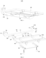
FIG. 1 is a schematic structural diagram of a mount bracket according to an embodiment of the present application. -
FIG. 2 is a schematic exploded structural diagram of the mount bracket inFIG. 1 . -
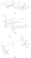
FIG. 3 is a schematic diagram of a support frame and a machine body shelf inFIG. 2 in a first assembly state. -
FIG. 4 is a schematic diagram of the support frame and the machine body shelf inFIG. 2 in a second assembly state. -
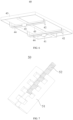
FIG. 5 is a schematic structural diagram of the support frame inFIG. 2 . -
FIG. 6 is a schematic structural diagram of the machine body shelf inFIG. 2 . -
FIG. 7 is a schematic structural diagram of a support foot inFIG. 2 . -
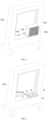
FIG. 8 is a schematic diagram of an air conditioner outdoor unit installed on a window frame through the mount bracket. -
FIG. 9 is a schematic structural diagram ofFIG. 8 without the air conditioner outdoor unit. -
FIG. 10 is a schematic installation structural diagram of the mount bracket and a double-layer window frame. -
FIG. 11 is a schematic structural diagram ofFIG. 10 without a wall. -
FIG. 12 is a schematic installation structural diagram of the mount bracket and an attic windowsill. -
reference sign name reference sign name 100 mount bracket 41 first assembly portion 10 fixation frame 42 second assembly portion 101 clamping groove 43 surrounding frame 102 fixation hole 44 support beam 11 main body portion 45 reinforcement beam 12 bend portion 46 reinforcement member 13 connection seat 50 support foot 20 fastener 51 damping foot pad 30 support frame 52 adjustment screw 31 connection beam 60 connection shaft 32 connection arm 200 window frame 321 connection position 300 windowsill 33 first mount portion 400 support surface 34 second mount portion 500 air conditioner outdoor unit 40 machine body shelf 600 wall 401 accommodation cavity - The realization of the objective, functional characteristics, and advantages of the present application are further described with reference to the accompanying drawings and in conjunction with the embodiments.
- The technical solutions of the embodiments of the present application will be clearly and completely described below with reference to the accompanying drawings. It is obvious that the embodiments to be described are only some rather than all of the embodiments of the present application. All other embodiments obtained by those skilled in the art based on the embodiments of the present application without creative efforts shall fall within the scope of the present application.
- It should be noted that if there are directional indications, such as up, down, left, right, front, back, etc, involved in the embodiments of the present application, the directional indications are only used to explain the relative position relationship and movement of the components in a certain posture. If the specific posture changes, the directional indication also changes accordingly.
- In addition, if there are descriptions related to "first", "second", etc. in the embodiments of the present application, the descriptions of "first", "second", etc. are only for the purpose of description, and should not be construed as indicating or implying relative importance or implicitly indicates the number of technical features indicated. Thus, a feature delimited with "first", "second" may expressly or implicitly include at least one of that feature. Besides, the meaning of "and/or" appearing in the application includes three parallel scenarios. For example, "A and/or B" includes only A, or only B, or both A and B. In addition, the technical solutions between the various embodiments can be combined with each other, but must be based on the realization by those skilled in the art. When the combination of technical solutions is contradictory or cannot be realized, it should be considered that the combination of such technical solutions does not exist or fall within the scope claimed in the present application.
- The present application provides a
mount bracket 100. - Referring to
FIG. 1, FIG. 2 , andFIG. 8 toFIG. 12 , in an embodiment of the present application, themount bracket 100 includes afixation frame 10, asupport frame 30 and amachine body shelf 40. Thefixation frame 10 is provided with a clampinggroove 101 with two through ends, the clampinggroove 101 is clamped to awindow frame 200 or awindowsill 300 through two opposite sidewalls, the sidewall is provided with afixation hole 102 for thefastener 20 to pass through, and thefixation frame 10 is locked to thewindow frame 200 or thewindowsill 300 through thefastener 20. Thesupport frame 30 is rotatably connected to thefixation frame 10, and thesupport frame 30 is abutted against thesupport surface 400 in the mounting environment. Themachine body shelf 40 is connected to thesupport frame 30, and themachine body shelf 40 is configured to place an air conditioner. - Specifically, the
mount bracket 100 is configured for the installation of the air conditioner, and the air conditioner includes, but not limited to, an air conditioneroutdoor unit 500, an air conditioner indoor unit or an air conditioner integrated unit. The following mainly takes the installation of the air conditioneroutdoor unit 500 through themount bracket 100 as an example for illustration. In actual use, depending on the mounting environment, thefixation frame 10 can be clamped on thewindow frame 200 or thewindowsill 300 through thefastener 20. Further, depending on the mounting environment, thesupport surface 400 for thesupport frame 30 to be abutted against in the mounting environment is also different. For example, as shown inFIG. 8 and FIG. 9 , under normal circumstances, the window of thewall 600 is provided with awindow frame 200, and a windowsill extending outward is formed below thewall 600 corresponding to the window. At this time, thefixation frame 10 can be clamped on thewindow frame 200, thesupport frame 30 is abutted against the surface of the windowsill, and the surface of the windowsill is thesupport surface 400. Alternatively, as shown inFIG. 10 and FIG. 11 , for a double window structure, thefixation frame 10 can be clamped on theupper window frame 200, and thesupport frame 30 can be abutted against thewindow frame 200 or the glass of the lower window. At this time, thewindow frame 200 or the glass of the lower window is thesupport surface 400. Alternatively, as shown inFIG. 12 , for the attic of a European family, the window is usually opened on the inclined roof wall, and there is no external window frame structure, but theentire windowsill 300 is configured to protrude from the roof wall. Thefixation frame 10 can be clamped on thewindowsill 300, and thesupport frame 30 can be abutted against the outer wall of the roof. At this time, the outer wall of the roof is thesupport surface 400. - The
fixation frame 10 extends along a length direction of thewindow frame 200 or thewindowsill 300. Thefixation frame 10 is provided with a clampinggroove 101 with two through ends. The clampinggroove 101 is provided with two opposite sidewalls and a top groove wall connected to the two sidewalls, and thus the cross section of thefixation frame 10 is a "U"-shaped structure, so as to be clamped to thewindow frame 200 or thewindowsill 300. The sidewall of the clampinggroove 101 is provided with afixation hole 102. The number of the fixation holes 102 can be set according to actual needs. In order to ensure the installation reliability, a plurality offixation holes 102 are usually provided, and the number offasteners 20 is adapted to the number of fixation holes 102. Thefixation hole 102 can be a threaded hole, and thefastener 20 can be a fasten screw rod adapted to the threaded hole. During assembly, thefixation frame 10 is clamped to thewindow frame 200 or thewindowsill 300 through the clampinggroove 101, and thefastener 20 is tightened through thefixation hole 102 and pressed against thewindow frame 200 or thewindowsill 300, so that thefixation frame 10 can be locked and fixed, and the operation is simple and convenient. One side of thesupport frame 30 is rotatably connected to thefixation frame 10, and the other side of thesupport frame 30 can be flipped relative to thefixation frame 10, so as to adapt to thesupport surface 400 in different mounting environments. Thesupport frame 30 and thefixation frame 10 are assembled before the user purchases, and the user does not need to install them by himself when using them. After thefixation frame 10 is installed, themachine body shelf 40 can be connected to thesupport frame 30, and the air conditioner (such as the air conditioner outdoor unit 500) can be supported by themachine body shelf 40. - In the technical solution of the present application, the
fixation frame 10 is provided with the clampinggroove 101. When the user installs the air conditioner (for example, the air conditioner outdoor unit 500), the user only needs to clamp thefixation frame 10 to thewindow frame 200 or thewindowsill 300 through the clampinggroove 101, and tighten thefastener 20 through thefixation hole 102 to press thefastener 20 against thewindow frame 200 or thewindowsill 300, so that thefixation frame 10 can be locked and fixed on thewindow frame 200 or thewindowsill 300. Thesupport frame 30 and thefixation frame 10 can be pre-assembled before leaving the factory, and there is no need for manual installation by the user. After thefixation frame 10 is installed by the user, themachine body shelf 40 can be connected to thesupport frame 30. The entire assembly process is simple and convenient, and the user can complete the installation of the air conditioner (such as the air conditioner outdoor unit 500) by himself. There is no need to drill holes on thewall 600, which can improve the installation efficiency and save the installation cost. In addition, by the means of the engagement between the clampinggroove 101 and thefastener 20, thefixation frame 10 can be fixed on thewindow frame 200 or thewindowsill 300 according to the actual mounting environment, and thesupport frame 30 is rotatably connected to thefixation frame 10, so that thesupport frame 30 can be adjusted in angle according to the mounting environment to be abutted against the correspondingsupport surface 400, and themount bracket 100 can be applied to different mounting environments, which can improve the versatility. - In order to further improve the versatility of the
mount bracket 100, as shown inFIG. 2 , in an embodiment, thefixation frame 10 includes amain body portion 11 extending in a horizontal direction and bendportions 12 bent upward respectively from both ends of themain body portion 11. The clampinggroove 101 includes a first groove section provided at themain body portion 11 and opening downward, and a second groove section provided at each of thebend portions 12 and opening towards one side facing away from themain body portion 11. The first groove section is interconnected to the second groove section. - In an embodiment, the
fixation frame 10 generally has a structure similar to a "C" shape or a "U" shape. Thebend portions 12 are provided respectively at both ends of themain body portion 11, to adapt to two forms of left window and right window. For example, the sidewall of the first groove section corresponding to themain body portion 11 is provided with twofixation holes 102 provided spaced apart along the length direction, and the sidewall of the second groove section corresponding to eachbend portion 12 is provided with afixation hole 102, that is, thefixation frame 10 is provided with fourfixation holes 102, and fourfasteners 20 are correspondingly provided. When it is applied to the mounting environment of the left window or the right window, it only needs to clamp themain body portion 11 to the bottom side of thewindow frame 200 through the first groove section, one of thebend portions 12 is clamped to the left side or the right side of thewindow frame 200 through the second groove section, and then threefasteners 20 are provided to lock and fix. When it is applied to the mounting environment of the attic window, themain body portion 11 can be clamped to thewindowsill 300 through the first groove section and then twofasteners 20 are provided to lock and fix. In this way, the versatility of themount bracket 100 can be further improved. - As shown in
FIG. 2 , in an embodiment, thesupport frame 30 is connected with asupport foot 50, and thesupport frame 30 is abutted against thesupport surface 400 through thesupport foot 50. Thesupport foot 50 can be adjusted relative to thesupport frame 30 along a normal direction of thesupport surface 400. Specifically, the normal direction of thesupport surface 400 refers to the direction perpendicular to thesupport surface 400. For example, when thesupport surface 400 is a horizontal plane, the normal direction of thesupport surface 400 is the vertical direction. Thesupport frame 30 is abutted against thesupport surface 400 through thesupport foot 50, and the position of thesupport foot 50 is adjusted, so that thesupport frame 30 can maintain an optimal support state. For example, as shown inFIG. 9 , under normal circumstances, awindow frame 200 is provided at the window of thewall 600, and a windowsill extending outward is formed below thewall 600 corresponding to the window. At this time, thefixation frame 10 can be clamped on thewindow frame 200, and thesupport frame 30 is abutted against the surface of the windowsill (that is, the support surface 400) through thesupport foot 50. By adjusting the position of thesupport foot 50, thesupport frame 30 can maintain a horizontal state. The specific number of thesupport foot 50 can be set according to actual needs, which can be one, two or more. - Further, as shown in
FIG. 7 , thesupport foot 50 includes a dampingfoot pad 51 and anadjustment screw 52. The dampingfoot pad 51 is connected to one end of theadjustment screw 52, and the other end of theadjustment screw 52 is threaded to thesupport frame 30. Thesupport foot 50 is abutted against thesupport surface 400 through the dampingfoot pad 51, and the dampingfoot pad 51 can be made of a rubber or silicone material with a certain flexibility, which can increase the friction with thesupport surface 400 to avoid slipping, and can also play a certain buffering and shock-absorbing role. Thesupport frame 30 is provided with a threaded hole for theadjustment screw 52 to pass through, and the position of thesupport foot 50 can be adjusted by screwing theadjustment screw 52, which is simple and convenient to operate, and can achieve fine adjustment of the position. - Referring to
FIG. 2 andFIG. 5 , in an embodiment, thesupport frame 30 includes aconnection beam 31 opposite to and extending in parallel with thefixation frame 10, and twoconnection arms 32 respectively provided at both ends of theconnection beam 31. Each of theconnection arms 32 is configured to extend towards thefixation frame 10 and is rotatably connected to thefixation frame 10. Each of theconnection arms 32 is connected to thesupport foot 50. - Specifically, the
support frame 30 is generally a "C"-shaped structure. The twoconnection arms 32 of thesupport frame 30 can be made of "U"-shaped iron, and theconnection beam 31 can be made of sheet metal strips. The two ends of theconnection beam 31 can be bent into a "U"-shaped structure, and welded and fixed to the ends of theconnection arm 32. Thefixation frame 10 is provided with aconnection seat 13 corresponding to each of theconnection arms 32. One end of each of theconnection arms 32 away from theconnection beam 31 can be rotatably connected to theconnection seat 13 through aconnection shaft 60, so that thesupport frame 30 can rotate relative to the fixing seat. Twosupport feet 50 are provided, and each of theconnection arms 32 is connected to onesupport foot 50. When theconnection arm 32 is rotated to a suitable position, thesupport foot 50 is abutted against thesupport surface 400, thereby ensuring the overall support reliability. - In order to further improve the versatility of the
mount bracket 100, as shown inFIG. 5 , in an embodiment, each of theconnection arms 32 is provided with a plurality ofconnection positions 321 along the length direction, and each of thesupport feet 50 can be selectively connected to one of the connection positions 321. In this way, the position of thesupport foot 50 can be adjusted along the length direction of theconnection arm 32, so as to adapt to different mounting environments. When thesupport foot 50 is threaded to theconnection arm 32, theconnection position 321 can be a threaded hole. - In order to ensure the installation stability of the air conditioner, as shown in
FIG. 2 , in an embodiment, themachine body shelf 40 is provided with anaccommodation cavity 401 for accommodating the bottom of the air conditioner. For example, when the air conditioneroutdoor unit 500 is placed on themachine body shelf 40, the bottom of the air conditioneroutdoor unit 500 is placed in theaccommodation cavity 401 of themachine body shelf 40, and the cavity wall around theaccommodation cavity 401 can play a certain limiting role on the air conditioneroutdoor unit 500, so as to prevent the air conditioneroutdoor unit 500 from sliding off themachine body shelf 40. - As shown in
FIG. 3 and FIG. 4 , on the basis of the above embodiment, in order to further improve the versatility of themount bracket 100, themachine body shelf 40 is detachably connected to thesupport frame 30 and can change the connection position to match with thesupport frame 30 to form different assembly states. In this way, the user can change the connection position of themachine body shelf 40 and thesupport frame 30 according to the actual mounting environment, so that an assembly state adapted to the mounting environment can be formed between themachine body shelf 40 and thesupport frame 30, so as to stably support the air conditioner. The detachable connection between themachine body shelf 40 and thesupport frame 30 includes, but not limited to, a plug-in matching, a snap-fit matching or a screw connection. - Referring to
FIG. 3 to FIG. 6 , in an embodiment, themachine body shelf 40 and thesupport frame 30 have a first assembly state and a second assembly state, thesupport frame 30 is provided with afirst mount portion 33 and asecond mount portion 34, and themachine body shelf 40 is provided with afirst assembly portion 41 and asecond assembly portion 42. As shown inFIG. 3 , in the first assembly state, thefirst assembly portion 41 is detachably connected to thefirst mount portion 33, so that themachine body shelf 40 is stacked on the top of thesupport frame 30. As shown inFIG. 4 , in the second assembly state, thesecond assembly portion 42 is detachably connected to thesecond mount portion 34, so that themachine body shelf 40 is unfolded at a preset angle relative to one side of thesupport frame 30 facing away from thesupport surface 400. - Specifically, as shown in
FIG. 8 and FIG. 9 , when themount bracket 100 is applied to a mounting environment provided with awindow frame 200 and a windowsill, thefixation frame 10 can be clamped on thewindow frame 200 through thefastener 20, thesupport frame 30 is supported on the surface of the windowsill (i.e., the support surface 400) through thesupport foot 50, and thesupport frame 30 is generally in a horizontal state. At this time, themachine body shelf 40 is detachably connected to thefirst mount portion 33 of thesupport frame 30 through thefirst assembly portion 41, so that themachine body shelf 40 is stacked on the top of thesupport frame 30, and themachine body shelf 40 is also generally in a horizontal state, so as to support the air conditioner (such as the air conditioner outdoor unit 500). As shown inFIG. 10 and FIG. 11 , when themount bracket 100 is applied to a mounting environment with a double window structure, thefixation frame 10 can be clamped on thewindow frame 200 of the upper window through thefastener 20, thesupport frame 30 is supported on thewindow frame 200 of the lower window or the glass (i.e., the support surface 400) through thesupport foot 50, and thesupport frame 30 is generally in a vertical state. At this time, themachine body shelf 40 is detachably connected to thesecond mount portion 34 of thesupport frame 30 through thesecond assembly portion 42, so that themachine body shelf 40 is extended at a preset angle (e.g., 90° ) relative to one side of thesupport frame 30 facing away from thesupport surface 400, that is, themachine body shelf 40 and thesupport frame 30 are assembled to generally present an "L"-shaped structure, so that themachine body shelf 40 can support the air conditioner (such as the air conditioner outdoor unit 500). As shown inFIG. 12 , when themount bracket 100 is applied to an attic mounting environment with awindowsill 300, thefixation frame 10 can be clamped on thewindowsill 300 through thefastener 20, thesupport frame 30 is supported on the outer wall surface of the attic roof (i.e., the support surface 400) through thesupport foot 50, and thesupport frame 30 is in an inclined state. At this time, themachine body shelf 40 is detachably connected to thesecond mount portion 34 of thesupport frame 30 through thesecond assembly portion 42, so that themachine body shelf 40 is extended at a preset angle (e.g., 90° ) relative to one side of thesupport frame 30 facing away from thesupport surface 400, that is, themachine body shelf 40 and thesupport frame 30 are assembled to generally present an "L"-shaped structure, so that themachine body shelf 40 can support the air conditioner (e.g., the air conditioner outdoor unit 500). - In order to further improve the installation convenience of the
machine body shelf 40 and thesupport frame 30, in an embodiment, in the first assembly state, thefirst assembly portion 41 is plugged and matched with thefirst mount portion 33. In the second assembly state, thesecond assembly portion 42 is plugged and matched with thesecond mount portion 34. In this way, whether it is the first assembly state or the second assembly state, the user only needs to complete the assembly of themachine body shelf 40 and thesupport frame 30 through a simple plug-in action, and the operation is simple and convenient. In an embodiment, thefirst mount portion 33 and thesecond mount portion 34 are both insertion slot structures, and thefirst assembly portion 41 and thesecond assembly portion 42 are both insertion sheet structures. - Further, as shown in
FIG. 5 andFIG. 6 , in an embodiment, themachine body shelf 40 includes a surroundingframe 43 and a main frame provided in the surroundingframe 43. The surroundingframe 43 includes two side frame edges opposite to each other, the main frame includes twosupport beams 44 opposite to each other, and both ends of each support beams 44 are respectively connected to the two side frame edges. The twosupport beams 44 are both provided with thefirst assembly portion 41, one of the side frame edges is provided with twosecond assembly portions 42 spaced apart along the length direction, and thesupport frame 30 is correspondingly provided with twofirst mount portions 33 and twosecond mount portions 34. - In an embodiment, the surrounding
frame 43 of themachine body shelf 40 may be formed into a rectangular frame structure by bending a sheet metal strip. The surroundingframe 43 includes two side frame edges opposite to each other in a width direction, and two side frame edges opposite to each other in a length direction. The main frame includes twosupport beams 44 spaced apart in the length direction of the surroundingframe 43, and two ends of each of the support beams 44 are respectively connected and fixed to two side frame edges in the width direction of the surroundingframe 43. In order to ensure the structural strength, both sides of each of the support beams 44 in the width direction are provided with flanges bent away from the surroundingframe 43, so that the cross section of thesupport beam 44 presents a "U"-shaped structure. The first assembly portion 41 (for example, a first inserting piece) extending towards the side facing away from the surroundingframe 43 is provided at the corresponding positions of the two support beams 44. Thefirst mount portion 33 is correspondingly provided at the outer sides of the twoconnection arms 32 of thesupport frame 30. Specifically, thefirst mount portion 33 can be bent into a " Ω " shape through a sheet metal sheet, and the opening side of thefirst mount portion 33 is welded and fixed to the outer side surface of theconnection arm 32, so that a first insertion slot for inserting thefirst assembly portion 41 is formed between thefirst mount portion 33 and theconnection arm 32. As shown inFIG. 3 , in the first assembly state, the twofirst assembly portions 41 can be inserted into the first insertion slots of the correspondingfirst mount portions 33. One side frame edge of the surroundingframe 43 is provided with two second assembly portions 42 (e.g., second inserting pieces) extending towards one side facing away from the surroundingframe 43 spaced apart along the length direction. Both ends of theconnection beam 31 of thesupport frame 30 are bent to form thesecond mount portion 34 in "U"-shaped, the ends of each of theconnection arms 32 are welded in the opening of thesecond mount portion 34, and the second insertion slot for inserting thesecond assembly portion 42 is formed between thesecond mount portion 34 and theconnection arm 32. As shown inFIG. 4 , in the second assembly state, the twosecond assembly portions 42 are inserted into the second insertion slots of the correspondingsecond mount portions 34. - In order to further enhance the structural strength of the
machine body shelf 40, as shown inFIG. 6 , the main frame further includes areinforcement beam 45 intersected and connected with the two support beams 44. Two ends of thereinforcement beam 45 are respectively connected and fixed to the two side frame edges in the length direction of the surroundingframe 43. Alternatively, each of the support beams 44 and the reinforcement beams 45 is configured in a "U"-shaped structure that is sunken relative to the surroundingframe 43, so that anaccommodation cavity 401 for accommodating the bottom of the air conditioner is formed between the surroundingframe 43 and the main frame. - In order to further enhance the structural strength of the
second assembly portion 42, as shown inFIG. 3 , in an embodiment, themachine body shelf 40 further includes areinforcement member 46 that is overlapped and connected with thesecond assembly portion 42. Specifically, thereinforcement member 46 can be directly welded to thesecond assembly portion 42 using a sheet metal sheet. Alternatively, thereinforcement member 46 is configured in a "T"-shaped structure, the lateral portion of thereinforcement member 46 is welded and fixed to the side frame edge of the surroundingframe 43, and the vertical portion of thereinforcement member 46 is welded and fixed to thesecond assembly portion 42, which can further enhance the structural strength. Twosecond assembly portions 42 are provided, and tworeinforcement members 46 are correspondingly provided. - The present application also provides an air conditioner, including an air conditioner indoor unit, an air conditioner
outdoor unit 500 and amount bracket 100. The air conditioner indoor unit is connected to the air conditioneroutdoor unit 500, and themount bracket 100 is configured to mount the air conditioneroutdoor unit 500. The specific structure of themount bracket 100 refers to the above embodiments. Since the present air conditioner adopts all the technical solutions of the above embodiments, it has at least all the beneficial effects brought by the technical solutions of the above embodiments, which will not be repeated here. - The above descriptions are only embodiments of the present application, and are not intended to limit the scope of the present application. Under the inventive concept of the present application, any equivalent structural transformations made by using the contents of the description and drawings of the present application, or direct/indirect applications in other related technical fields, are included in the scope of the present application.
Claims (13)
- A mount bracket, characterized by:a fixation frame provided with a clamping groove with two through ends, wherein the clamping groove is clamped to a window frame or a windowsill through two opposite sidewalls, the sidewall is provided with a fixation hole for a fastener to pass through, and the fixation frame is locked to the window frame or the windowsill through the fastener;a support frame rotatably connected to the fixation frame and abutted against a support surface in a mounting environment; anda machine body shelf connected to the support frame and configured to place an air conditioner.
- The mount bracket according to claim 1, wherein the fixation frame comprises a main body portion extending in a horizontal direction and bend portions bent upward respectively from both ends of the main body portion, the clamping groove comprises a first groove section provided at the main body portion and opening downward and a second groove section provided in each of the bend portions and opening towards one side facing away from the main body portion, and the first groove section is interconnected to the second groove section.
- The mount bracket according to claim 1, wherein the support frame is connected with a support foot, the support frame is abutted against the support surface through the support foot, and the support foot is adjustable in position relative to the support frame along a normal direction of the support surface.
- The mount bracket according to claim 3, wherein the support foot comprises a damping foot pad and an adjustment screw, the damping foot pad is connected to one end of the adjustment screw, and the other end of the adjustment screw is threaded to the support frame.
- The mount bracket according to claim 3, wherein the support frame comprises a connection beam opposite to and extending in parallel with the fixation frame and two connection arms respectively provided at both ends of the connection beam, each of the connection arms extends toward the fixation frame and is rotatably connected to the fixation frame, and each of the connection arms is connected to the support foot.
- The mount bracket according to claim 5, wherein each of the connection arms is provided with a plurality of connection positions along a length direction, and each of the support feet is selectively connected to one of the connection positions.
- The mount bracket according to claim 1, wherein the machine body shelf is provided with an accommodation cavity for accommodating a bottom of the air conditioner.
- The mount bracket according to any one of claims 1 to 7, wherein the machine body shelf is detachably connected to the support frame and can change a connection position, to match with the support frame to form different assembly states.
- The mount bracket according to claim 8, wherein the machine body shelf and the support frame have a first assembly state and a second assembly state, the support frame is provided with a first mount portion and a second mount portion, and the machine body shelf is provided with a first assembly portion and a second assembly portion;in the first assembly state, the first assembly portion is detachably connected to the first mount portion, so that the machine body shelf is stacked on a top of the support frame; andin the second assembly state, the second assembly portion is detachably connected to the second mount portion, so that the machine body shelf is unfolded at a preset angle relative to the support frame toward one side facing away from the support surface.
- The mount bracket according to claim 9, wherein in the first assembly state, the first assembly portion is plugged and matched with the first mount portion; and
in the second assembly state, the second assembly portion is plugged and matched with the second mount portion. - The mount bracket according to claim 9, wherein the machine body shelf comprises a surrounding frame and a main frame provided in the surrounding frame, the surrounding frame comprises two opposite side frame edges, the main frame comprises two opposite support beams, two ends of each of the support beams are respectively connected to the two side frame edges, the two support beams are provided with the first assembly portion, one of the side frame edges is provided with two second assembly portions spaced apart along a length direction, and the support frame is correspondingly provided with two first mount portions and two second mount portions.
- The mount bracket according to claim 9, wherein the machine body shelf further comprises a reinforcement member stacked and connected to the second assembly portion.
- An air conditioner, comprising an air conditioner indoor unit, an air conditioner outdoor unit and the mount bracket according to any one of claims 1 to 12, wherein the air conditioner indoor unit is connected to the air conditioner outdoor unit, and the mount bracket is configured to mount the air conditioner outdoor unit.
Applications Claiming Priority (3)
| Application Number | Priority Date | Filing Date | Title |
|---|---|---|---|
| CN202222617747.4U CN218096553U (en) | 2022-09-28 | 2022-09-28 | Installing support and air conditioner |
| CN202211218517.9A CN117824139A (en) | 2022-09-28 | 2022-09-28 | Mounting bracket and air conditioner |
| PCT/CN2022/127228 WO2024065912A1 (en) | 2022-09-28 | 2022-10-25 | Mounting support and air conditioner |
Publications (2)
| Publication Number | Publication Date |
|---|---|
| EP4553400A1 true EP4553400A1 (en) | 2025-05-14 |
| EP4553400A4 EP4553400A4 (en) | 2025-11-19 |
Family
ID=90475673
Family Applications (1)
| Application Number | Title | Priority Date | Filing Date |
|---|---|---|---|
| EP22960512.6A Pending EP4553400A4 (en) | 2022-09-28 | 2022-10-25 | MOUNTING RACK AND AIR CONDITIONING |
Country Status (2)
| Country | Link |
|---|---|
| EP (1) | EP4553400A4 (en) |
| WO (1) | WO2024065912A1 (en) |
Family Cites Families (9)
| Publication number | Priority date | Publication date | Assignee | Title |
|---|---|---|---|---|
| JPH08193729A (en) * | 1994-11-14 | 1996-07-30 | Inoac Corp | Roof frame for outdoor machine of room air conditioner |
| US7296424B2 (en) * | 2005-09-29 | 2007-11-20 | Whirlpool Corporation | Mounting system and method for mounting an air conditioner |
| CN201262445Y (en) * | 2008-08-06 | 2009-06-24 | 陈启仁 | Air conditioner and its installation apparatus |
| RU2554734C1 (en) * | 2014-01-31 | 2015-06-27 | Юрий Васильевич Леонард | Method to install window air conditioner |
| WO2019114943A1 (en) * | 2017-12-13 | 2019-06-20 | Electrolux Appliances Aktiebolag | Installation device for split air-conditioner |
| CN108679746A (en) * | 2018-07-27 | 2018-10-19 | 安徽金鸿盛电气有限公司 | Portable air-conditioning mounting bracket |
| CN114746701A (en) * | 2019-09-13 | 2022-07-12 | 特劳公司 | Window installation system and method for split architecture air conditioning unit |
| CN215260527U (en) * | 2021-06-30 | 2021-12-21 | 芜湖美智空调设备有限公司 | Installation mechanism of integral type air conditioner and integral type air conditioner equipment |
| CN217402706U (en) * | 2022-05-31 | 2022-09-09 | 芜湖美智空调设备有限公司 | Outer quick-witted mounting bracket and air conditioner |
-
2022
- 2022-10-25 EP EP22960512.6A patent/EP4553400A4/en active Pending
- 2022-10-25 WO PCT/CN2022/127228 patent/WO2024065912A1/en not_active Ceased
Also Published As
| Publication number | Publication date |
|---|---|
| WO2024065912A1 (en) | 2024-04-04 |
| EP4553400A4 (en) | 2025-11-19 |
Similar Documents
| Publication | Publication Date | Title |
|---|---|---|
| US11397023B2 (en) | Connection member, mounting bracket assembly, and window air conditioner assembly | |
| US6923413B2 (en) | Mounting device for a flat screen display panel | |
| WO2021120415A1 (en) | Connecting piece, mounting frame assembly and window type air conditioner assembly | |
| CN211261058U (en) | Mounting Bracket Assembly and Window Air Conditioner Assembly | |
| CN111306645B (en) | Connectors, supports, mounting bracket assemblies and window air conditioner assemblies | |
| US12181178B2 (en) | Mounting bracket assembly and window air conditioner assembly | |
| CN117824139A (en) | Mounting bracket and air conditioner | |
| EP4553400A1 (en) | Mounting support and air conditioner | |
| CN219083370U (en) | Mounting bracket and air conditioner | |
| CN211261044U (en) | Mounting Shell, Mounting Bracket Assembly, Window Air Conditioner Assembly | |
| CN117190335B (en) | Outer machine mounting frame and air conditioner | |
| CN211177127U (en) | Air conditioner indoor unit and air conditioner | |
| CN220771359U (en) | Air conditioner installing support convenient to adjust | |
| CN218096321U (en) | Installing support, outer quick-witted subassembly of air conditioner and air conditioner | |
| CN216244854U (en) | Wall-mounted device of indoor unit of air conditioner and air conditioner | |
| CN216218287U (en) | Two-way buckle, automatically controlled subassembly and air conditioner | |
| CN212224509U (en) | Wood veneer component | |
| CA3086265C (en) | Connection member, mounting bracket assembly, and window air conditioner assembly | |
| CA3087638C (en) | Mounting bracket assembly and window air conditioner assembly | |
| CN112984642B (en) | Mounting bracket assembly and window air conditioner assembly | |
| CN222514083U (en) | Installation structure and air conditioning | |
| WO2025241375A1 (en) | Chassis, mounting bracket, mounting structure and air conditioner | |
| CN224065602U (en) | Mounting bracket and air conditioner | |
| CN210861439U (en) | The installation structure of the side panel of the outer unit of the air conditioner | |
| CN224162731U (en) | Mounting brackets and air conditioners |
Legal Events
| Date | Code | Title | Description |
|---|---|---|---|
| STAA | Information on the status of an ep patent application or granted ep patent |
Free format text: STATUS: THE INTERNATIONAL PUBLICATION HAS BEEN MADE |
|
| PUAI | Public reference made under article 153(3) epc to a published international application that has entered the european phase |
Free format text: ORIGINAL CODE: 0009012 |
|
| STAA | Information on the status of an ep patent application or granted ep patent |
Free format text: STATUS: REQUEST FOR EXAMINATION WAS MADE |
|
| 17P | Request for examination filed |
Effective date: 20250210 |
|
| AK | Designated contracting states |
Kind code of ref document: A1 Designated state(s): AL AT BE BG CH CY CZ DE DK EE ES FI FR GB GR HR HU IE IS IT LI LT LU LV MC ME MK MT NL NO PL PT RO RS SE SI SK SM TR |
|
| A4 | Supplementary search report drawn up and despatched |
Effective date: 20251020 |
|
| RIC1 | Information provided on ipc code assigned before grant |
Ipc: F24F 13/32 20060101AFI20251014BHEP Ipc: F24F 1/60 20110101ALI20251014BHEP Ipc: F16M 13/02 20060101ALI20251014BHEP |
|
| DAV | Request for validation of the european patent (deleted) | ||
| DAX | Request for extension of the european patent (deleted) |