EP4553399A1 - Utilization unit and refrigeration device - Google Patents
Utilization unit and refrigeration device Download PDFInfo
- Publication number
- EP4553399A1 EP4553399A1 EP24731449.5A EP24731449A EP4553399A1 EP 4553399 A1 EP4553399 A1 EP 4553399A1 EP 24731449 A EP24731449 A EP 24731449A EP 4553399 A1 EP4553399 A1 EP 4553399A1
- Authority
- EP
- European Patent Office
- Prior art keywords
- transmission line
- sensor
- refrigerant
- utilization unit
- connector
- Prior art date
- Legal status (The legal status is an assumption and is not a legal conclusion. Google has not performed a legal analysis and makes no representation as to the accuracy of the status listed.)
- Granted
Links
Images


Classifications
-
- F—MECHANICAL ENGINEERING; LIGHTING; HEATING; WEAPONS; BLASTING
- F24—HEATING; RANGES; VENTILATING
- F24F—AIR-CONDITIONING; AIR-HUMIDIFICATION; VENTILATION; USE OF AIR CURRENTS FOR SCREENING
- F24F1/00—Room units for air-conditioning, e.g. separate or self-contained units or units receiving primary air from a central station
- F24F1/0007—Indoor units, e.g. fan coil units
-
- F—MECHANICAL ENGINEERING; LIGHTING; HEATING; WEAPONS; BLASTING
- F24—HEATING; RANGES; VENTILATING
- F24F—AIR-CONDITIONING; AIR-HUMIDIFICATION; VENTILATION; USE OF AIR CURRENTS FOR SCREENING
- F24F1/00—Room units for air-conditioning, e.g. separate or self-contained units or units receiving primary air from a central station
- F24F1/0007—Indoor units, e.g. fan coil units
- F24F1/0043—Indoor units, e.g. fan coil units characterised by mounting arrangements
-
- F—MECHANICAL ENGINEERING; LIGHTING; HEATING; WEAPONS; BLASTING
- F24—HEATING; RANGES; VENTILATING
- F24F—AIR-CONDITIONING; AIR-HUMIDIFICATION; VENTILATION; USE OF AIR CURRENTS FOR SCREENING
- F24F1/00—Room units for air-conditioning, e.g. separate or self-contained units or units receiving primary air from a central station
- F24F1/02—Self-contained room units for air-conditioning, i.e. with all apparatus for treatment installed in a common casing
- F24F1/029—Self-contained room units for air-conditioning, i.e. with all apparatus for treatment installed in a common casing characterised by the layout or mutual arrangement of components, e.g. of compressors or fans
-
- F—MECHANICAL ENGINEERING; LIGHTING; HEATING; WEAPONS; BLASTING
- F24—HEATING; RANGES; VENTILATING
- F24F—AIR-CONDITIONING; AIR-HUMIDIFICATION; VENTILATION; USE OF AIR CURRENTS FOR SCREENING
- F24F11/00—Control or safety arrangements
- F24F11/89—Arrangement or mounting of control or safety devices
-
- F—MECHANICAL ENGINEERING; LIGHTING; HEATING; WEAPONS; BLASTING
- F24—HEATING; RANGES; VENTILATING
- F24F—AIR-CONDITIONING; AIR-HUMIDIFICATION; VENTILATION; USE OF AIR CURRENTS FOR SCREENING
- F24F13/00—Details common to, or for air-conditioning, air-humidification, ventilation or use of air currents for screening
- F24F13/20—Casings or covers
-
- F—MECHANICAL ENGINEERING; LIGHTING; HEATING; WEAPONS; BLASTING
- F24—HEATING; RANGES; VENTILATING
- F24F—AIR-CONDITIONING; AIR-HUMIDIFICATION; VENTILATION; USE OF AIR CURRENTS FOR SCREENING
- F24F1/00—Room units for air-conditioning, e.g. separate or self-contained units or units receiving primary air from a central station
- F24F1/02—Self-contained room units for air-conditioning, i.e. with all apparatus for treatment installed in a common casing
- F24F1/028—Self-contained room units for air-conditioning, i.e. with all apparatus for treatment installed in a common casing characterised by air supply means, e.g. fan casings, internal dampers or ducts
- F24F1/0284—Self-contained room units for air-conditioning, i.e. with all apparatus for treatment installed in a common casing characterised by air supply means, e.g. fan casings, internal dampers or ducts with horizontally arranged fan axis
-
- F—MECHANICAL ENGINEERING; LIGHTING; HEATING; WEAPONS; BLASTING
- F24—HEATING; RANGES; VENTILATING
- F24F—AIR-CONDITIONING; AIR-HUMIDIFICATION; VENTILATION; USE OF AIR CURRENTS FOR SCREENING
- F24F11/00—Control or safety arrangements
- F24F11/30—Control or safety arrangements for purposes related to the operation of the system, e.g. for safety or monitoring
- F24F11/32—Responding to malfunctions or emergencies
- F24F11/36—Responding to malfunctions or emergencies to leakage of heat-exchange fluid
-
- F—MECHANICAL ENGINEERING; LIGHTING; HEATING; WEAPONS; BLASTING
- F24—HEATING; RANGES; VENTILATING
- F24F—AIR-CONDITIONING; AIR-HUMIDIFICATION; VENTILATION; USE OF AIR CURRENTS FOR SCREENING
- F24F13/00—Details common to, or for air-conditioning, air-humidification, ventilation or use of air currents for screening
- F24F13/02—Ducting arrangements
- F24F13/029—Duct comprising an opening for inspection, e.g. manhole
-
- F—MECHANICAL ENGINEERING; LIGHTING; HEATING; WEAPONS; BLASTING
- F24—HEATING; RANGES; VENTILATING
- F24F—AIR-CONDITIONING; AIR-HUMIDIFICATION; VENTILATION; USE OF AIR CURRENTS FOR SCREENING
- F24F13/00—Details common to, or for air-conditioning, air-humidification, ventilation or use of air currents for screening
- F24F13/30—Arrangement or mounting of heat-exchangers
-
- F—MECHANICAL ENGINEERING; LIGHTING; HEATING; WEAPONS; BLASTING
- F24—HEATING; RANGES; VENTILATING
- F24F—AIR-CONDITIONING; AIR-HUMIDIFICATION; VENTILATION; USE OF AIR CURRENTS FOR SCREENING
- F24F13/00—Details common to, or for air-conditioning, air-humidification, ventilation or use of air currents for screening
- F24F13/20—Casings or covers
- F24F2013/205—Mounting a ventilator fan therein
-
- F—MECHANICAL ENGINEERING; LIGHTING; HEATING; WEAPONS; BLASTING
- F24—HEATING; RANGES; VENTILATING
- F24F—AIR-CONDITIONING; AIR-HUMIDIFICATION; VENTILATION; USE OF AIR CURRENTS FOR SCREENING
- F24F13/00—Details common to, or for air-conditioning, air-humidification, ventilation or use of air currents for screening
- F24F13/20—Casings or covers
- F24F2013/207—Casings or covers with control knobs; Mounting controlling members or control units therein
Definitions
- This disclosure relates to a utilization unit provided with a refrigerant sensor configured to detect a leaked refrigerant, and a refrigeration apparatus including the utilization unit.
- Patent Literature 1 Japanese Laid-Open Patent Publication No. 2019-011914A discloses a utilization unit including a case and a refrigerant sensor.
- the refrigerant sensor detects a refrigerant leaked in the case.
- a material for the refrigerant sensor is changed in physical property. This change may cause performance deterioration or life shortening of the refrigerant sensor.
- the refrigerant sensor is thus ideally replaced with a new product each time the refrigerant sensor detects a refrigerant. Designing a utilization unit to facilitate replacement work for a refrigerant sensor is important in terms of maintenance work for a refrigeration apparatus having been installed.
- a utilization unit includes a case, a partition plate, a fan, an electric component box, a heat exchanger, a first sensor, a first transmission line, and a first connector.
- the partition plate divides the interior of the case into a fan chamber and a heat exchange chamber.
- the fan and the electric component box are disposed in the fan chamber.
- the heat exchanger and the first sensor are disposed in the heat exchange chamber.
- the first sensor detects a refrigerant having leaked.
- the first transmission line extends from the electric component box to the heat exchange chamber through a passage of the partition plate.
- the first connector is disposed in the heat exchange chamber. The first connector connects the first transmission line and the first sensor.
- the first sensor can be separated from the electric component box with use of the first connector. This facilitates replacement of the first sensor. Specifically, a transmission line connecting the electric component box and the first sensor does not need to be extracted from and inserted to the partition plate for replacement of the first sensor. This can inhibit damage to the transmission line due to extraction or insertion, and can inhibit deterioration in sealing performance between the transmission line and the partition plate.
- a utilization unit is the utilization unit according to the first aspect, in which the case has a first surface and a second surface.
- the first surface has a blow-out port allowing conditioned air to pass therethrough.
- the second surface has a maintenance opening allowing treatment of the first sensor by a worker.
- the maintenance opening and the blow-out port are provided in the different surfaces of the case.
- the maintenance opening can thus have a secured area for facilitation of maintenance work.
- a utilization unit is the utilization unit according to the second aspect, and further includes a second transmission line.
- the second transmission line extends from the first sensor to the first connector.
- the second transmission line is provided to allow the first sensor to be spaced apart from the first connector. This enhances flexibility in positioning of the first sensor and facilitates maintenance work.
- a utilization unit is the utilization unit according to the third aspect, and further includes a transmission line retainer.
- the transmission line retainer retains the first connector, or retains both the first transmission line and the second transmission line.
- part of a wire connecting the first connector and the first sensor is bound to a position of the transmission line retainer.
- the wire is less likely to be away from a hand of a worker to facilitate maintenance work.
- a utilization unit is the utilization unit according to the fourth aspect, and further includes a maintenance lid.
- the maintenance lid closes the maintenance opening.
- At least one of the first sensor or the transmission line retainer is fixed to the maintenance lid.
- the first sensor or the transmission line retainer is fixed to the maintenance lid.
- the first sensor or the transmission line retainer is thus pulled out of the case when a worker detaches the maintenance lid, which facilitates maintenance work.
- a utilization unit is the utilization unit according to any one of the first to fifth aspects, and further includes a second sensor.
- the second sensor is disposed in the heat exchange chamber.
- the second sensor detects a phenomenon other than leakage of the refrigerant.
- a transmission line extending from the electric component box and connecting the second sensor is not connected to any connector.
- the transmission line for the first sensor is provided with the first connector, whereas the transmission line for the second sensor is not provided with any connector. This facilitates replacement work for the first sensor that needs to be replaced, and can inhibit superposition of noise caused by connector contact resistance or the like on a signal line for the second sensor that does not need to be replaced.
- a utilization unit is the utilization unit according to any one of the first to sixth aspects, and further includes a second connector.
- the second connector is configured to separate the first transmission line from the electric component box.
- the second connector is provided to allow the first transmission line to be separated from the electric component box. This facilitates routing work for the first transmission line in a step of manufacturing the utilization unit.
- a utilization unit is the utilization unit according to any one of the first to seventh aspects, and further includes a sealing material.
- the sealing material is provided at the passage. The sealing material inhibits an air flow from passing through the passage.
- the passage of the partition plate is provided with the sealing material. This inhibits an unpreferred air flow from passing between the fan chamber and the heat exchange chamber.
- a refrigeration apparatus includes the utilization unit according to any one of the first to eighth aspects.
- the refrigeration apparatus thus configured facilitates replacement work for the first sensor.
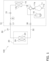
- FIG. 1 depicts a refrigeration apparatus 100 according to an embodiment.
- the refrigeration apparatus 100 can include various devices such an air conditioner, a refrigerator, a freezer, a hot water supplier, and a floor heater.
- the refrigeration apparatus 100 according to the present embodiment is an air conditioner.
- the refrigeration apparatus 100 is constituted by a heat source unit 10, a utilization unit 20, and a refrigerant pipe group 30 connecting the heat source unit 10 and the utilization unit 20.
- the refrigeration apparatus 100 includes a refrigerant circuit for circulation of a refrigerant R.
- the heat source unit 10 includes, as components of the refrigerant circuit, a compressor 11, a four-way switching valve 12, a heat source heat exchanger 13, a heat source expansion valve 15, an accumulator 16, a liquid shutoff valve 17, and a gas shutoff valve 18.
- the utilization unit 20 includes a utilization heat exchanger 23 as a component of the refrigerant circuit.
- the refrigerant pipe group 30 includes a liquid connection pipe 31 and a gas connection pipe 32 as components of the refrigerant circuit.
- Cold heat utilization operation is an operation in which the refrigeration apparatus 100 provides a user with cold heat.
- the compressor 11 sucks a low-pressure gas refrigerant from a suction tube 11a and then compresses it to generate a high-pressure gas refrigerant to be discharged from a discharge tube 11b.
- the four-way switching valve 12 achieves connection indicated by solid lines in FIG. 1 .
- the heat source heat exchanger 13 condenses the high-pressure gas refrigerant to generate a high-pressure liquid refrigerant.
- a heat source fan 14 promotes heat exchange between the refrigerant and the air in the heat source heat exchanger 13.
- the heat source expansion valve 15 decompresses the high-pressure liquid refrigerant to generate a low-pressure gas-liquid two-phase refrigerant.
- the low-pressure gas-liquid two-phase refrigerant passes through the liquid shutoff valve 17 and the liquid connection pipe 31 to reach the utilization heat exchanger 23.
- the utilization heat exchanger 23 evaporates the gas-liquid two-phase refrigerant to generate a low-pressure gas refrigerant, generating cold heat to be supplied to a user during this process.
- a utilization fan 24 promotes heat exchange between the refrigerant and the air in the utilization heat exchanger 23.
- the low-pressure gas refrigerant passes through the gas connection pipe 32, the gas shutoff valve 18, and the four-way switching valve 12 to reach the accumulator 16.
- the accumulator 16 separates a fluid component mixed in the low-pressure gas refrigerant and reserves the fluid component.
- the low-pressure gas refrigerant flowing out of the accumulator 16 is sucked from the suction tube 11a by the compressor 11.
- Hot heat utilization operation is an operation in which the refrigeration apparatus 100 provides a user with hot heat.
- the compressor 11 sucks a low-pressure gas refrigerant from the suction tube 11a and then compresses it to generate a high-pressure gas refrigerant to be discharged from the discharge tube 11b.
- the four-way switching valve 12 achieves connection indicated by broken lines in FIG. 1 .
- the high-pressure gas refrigerant passes through the four-way switching valve 12, the gas shutoff valve 18, and the gas connection pipe 32 to reach the utilization heat exchanger 23.
- the utilization heat exchanger 23 condenses the high-pressure gas refrigerant to generate a high-pressure liquid refrigerant, generating hot heat to be supplied to a user during this process.
- the utilization fan 24 promotes heat exchange between the refrigerant and the air in the utilization heat exchanger 23.
- the high-pressure liquid refrigerant passes through the liquid connection pipe 31 and the liquid shutoff valve 17 to reach the heat source expansion valve 15.
- the heat source expansion valve 15 decompresses the high-pressure liquid refrigerant to generate a low-pressure gas-liquid two-phase refrigerant.
- the heat source heat exchanger 13 evaporates the low-pressure gas-liquid two-phase refrigerant to generate a low-pressure gas refrigerant.
- the heat source fan 14 promotes heat exchange between the refrigerant and the air in the heat source heat exchanger 13.
- the low-pressure gas refrigerant reaches the accumulator 16 via the four-way switching valve 12.
- the accumulator 16 separates a fluid component mixed in the low-pressure gas refrigerant and reserves the fluid component.
- the low-pressure gas refrigerant flowing out of the accumulator 16 is sucked from the suction tube 11a by the compressor 11.
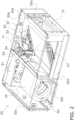
- FIG. 2 depicts a configuration of the utilization unit 20.
- the utilization unit 20 includes a case 50, a partition plate 53, the utilization heat exchanger 23, the utilization fan 24, an electric component box 61, a refrigerant sensor 65, a thermistor 67, and a maintenance lid 71.
- the case 50 accommodates components constituting the utilization unit 20 including the utilization heat exchanger 23 and the utilization fan 24.
- FIG. 2 does not depict part of the members of the case 50 to enable visual recognition of the interior of the utilization unit 20.
- the case 50 has a rectangular parallelepiped shape, and has a first side surface 50a, a second side surface 50b, a third side surface 50c, a fourth side surface 50d, an upper surface 50e, and a lower surface 50f.
- the first side surface 50a is provided with a blow-out port 51 configured to allow conditioned air to blow out.
- the second side surface 50b adjacent to the first side surface 50a is provided with a maintenance opening 52.
- the maintenance opening 52 allows treatment including replacement of the refrigerant sensor 65 by a maintenance worker.
- the lower surface 50f is provided with a suction port for intake of air.
- the partition plate 53 is provided in the case 50.
- the partition plate 53 divides an internal space of the case 50 into a fan chamber 57 and a heat exchange chamber 58.
- the partition plate 53 is provided with a passage 54 allowing wiring to pass therethrough. Examples of the passage 54 include a hole and a cutout.
- the utilization heat exchanger 23 causes heat exchange between the refrigerant R and the air.
- the utilization heat exchanger 23 is disposed in the heat exchange chamber 58.
- the utilization heat exchanger 23 functions as an evaporator during the cold heat utilization operation.
- the utilization heat exchanger 23 functions as a condenser during the hot heat utilization operation.
- the utilization fan 24 generates an air flow passing through the utilization heat exchanger 23.
- the utilization fan 24 is disposed in the fan chamber 57.
- the air flow having passed through the utilization heat exchanger 23 is discharged from the blow-out port 51.
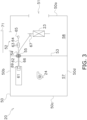
- FIG. 3 is a schematic view of an internal configuration of the utilization unit 20.
- the electric component box 61 accommodates a power source unit and electric circuit components.
- the electric component box 61 is disposed in the fan chamber 57.
- the electric component box 61 includes an electric component box connector 69.
- the electric component box connector 69 connects or disconnects wiring to or from the electric component box 61.
- the electric component box connector 69 includes a housing connected to a first transmission line 62 and a thermistor transmission line 66 to be described later.
- the refrigerant sensor 65 detects a refrigerant leaked from the refrigerant circuit. As depicted in FIG. 3 , the refrigerant sensor 65 is disposed in the heat exchange chamber 58.
- transmission line is not limited to a signal line and includes a power source line or a ground line.
- the first transmission line 62 extends from the electric component box connector 69 in the fan chamber 57 to a relay connector 63 disposed in the heat exchange chamber 58 via the passage 54.
- the relay connector 63 includes two housings configured to be fitted to each other, and one is connected to the first transmission line 62 whereas the other is connected to the second transmission line 64.
- the second transmission line 64 connects the relay connector 63 and the refrigerant sensor 65.
- the passage 54 is provided with a sealing material 55. The sealing material 55 fills the gap of the passage 54 so as to allow the first transmission line 62 to pass therethrough and prevent an air flow from passing therethrough.
- the thermistor 67 detects temperature of a refrigerant.
- the thermistor 67 is disposed in the heat exchange chamber 58. Connection between the thermistor 67 and the electric component box 61 is achieved by the thermistor transmission line 66.
- the thermistor transmission line 66 passes through the passage 54.
- the thermistor transmission line 66 is not connected to any relaying connector.
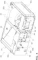
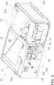
- FIG. 4 and FIG. 5 shows perspective views of the utilization unit 20 on the side of the second side surface 50b.
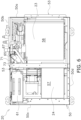
- FIG. 6 is a plan view of the utilization unit 20. Part of the members of the case 50 are not depicted in FIG. 4 to FIG. 6 to enable visual recognition of the interior of the utilization unit 20.
- the second side surface 50b is provided with the maintenance lid 71.
- the maintenance lid 71 closes the maintenance opening 52.
- FIG. 5 depicts the maintenance opening 52 not provided with the maintenance lid 71.
- FIG. 6 indicates that the refrigerant sensor 65 is positioned near the maintenance lid 71. A maintenance worker can execute replacement and the like of the refrigerant sensor 65 when the maintenance lid 71 is detached.
- FIG. 7 depicts configurations around the maintenance opening 52.
- the maintenance lid 71 closes the maintenance opening 52.
- the transmission line retainer 72 is fixed to the maintenance lid 71.
- the transmission line retainer 72 retains both the first transmission line 62 and the second transmission line 64 at a clamp part 72a.
- a relay connector protector 73 fixed to the transmission line retainer 72.
- the relay connector protector 73 covers part of the first transmission line 62, the relay connector 63, and part of the second transmission line 64.
- the refrigerant sensor 65 is fixed to the transmission line retainer 72.
- the transmission line retainer 72, the relay connector protector 73, the first transmission line 62, the relay connector 63, the second transmission line 64, and the refrigerant sensor 65 which are directly or indirectly fixed to the maintenance lid 71, are ejected out of the case 50.
- the relay connector 63 positioned near the maintenance opening 52 can separate the refrigerant sensor 65 from the electric component box 61. This facilitates replacement work for the refrigerant sensor 65. Specifically, a transmission line connecting the electric component box 61 and the refrigerant sensor 65 does not need to be extracted from and inserted to the partition plate 53 for replacement of the refrigerant sensor 65. This can inhibit damage to the transmission line due to extraction or insertion, and can inhibit deterioration in sealing performance between the transmission line and the partition plate 53.
- the case 50 has the maintenance opening 52 and the blow-out port 51 disposed in the different surfaces.
- the maintenance opening 52 can thus have a secured area for facilitation of maintenance work.
- the second transmission line 64 is provided to allow the refrigerant sensor 65 to be spaced apart from the relay connector 63. This enhances flexibility in positioning of the refrigerant sensor 65 and facilitates maintenance work.
- a transmission line for the refrigerant sensor 65 is provided with the relay connector 63, whereas a transmission line for the thermistor 67 is not provided with any connector. This facilitates replacement work for the refrigerant sensor 65 that needs to be replaced, and can inhibit superposition of noise caused by connector contact resistance or the like on a signal line for the thermistor that does not need to be replaced.
- the electric component box connector 69 is provided to allow the first transmission line 62 to be separated from the electric component box 61. This facilitates routing work for the first transmission line 62 in a step of manufacturing the utilization unit 20.
- the passage 54 of the partition plate 53 is provided with the sealing material 55. This inhibits an unpreferred air flow from passing between the fan chamber 57 and the heat exchange chamber 58.
- the transmission line retainer 72 retains both the first transmission line 62 and the second transmission line 64.
- the transmission line retainer 72 may retain one of the housings of the relay connector 63.
- the transmission line retainer 72 may retain at least one of the first transmission line 62 or the second transmission line 64 in addition to the one of the housings of the relay connector 63.
- the first transmission line 62 and the thermistor transmission line 66 pass through the common passage 54.
- the partition plate 53 may include a plurality of passages 54 and the first transmission line 62 and the thermistor transmission line 66 may pass through the passages 54 different from each other.
- both the transmission line retainer 72 and the refrigerant sensor 65 are directly or indirectly fixed to the maintenance lid 71.
- only one of the transmission line retainer 72 and the refrigerant sensor 65 may be fixed to the maintenance lid 71.
- the refrigeration apparatus 100 is an air conditioner.
- the refrigeration apparatus 100 may alternatively be configured as a device other than the air conditioner, such as a refrigerator, a freezer, a hot water supplier, or a floor heater.
- Patent Literature 1 JP 2019-011914 A
Landscapes
- Engineering & Computer Science (AREA)
- Chemical & Material Sciences (AREA)
- Combustion & Propulsion (AREA)
- Mechanical Engineering (AREA)
- General Engineering & Computer Science (AREA)
- Air Conditioning Control Device (AREA)
- Other Air-Conditioning Systems (AREA)
- Devices That Are Associated With Refrigeration Equipment (AREA)
- Air Filters, Heat-Exchange Apparatuses, And Housings Of Air-Conditioning Units (AREA)
Abstract
Description
- This disclosure relates to a utilization unit provided with a refrigerant sensor configured to detect a leaked refrigerant, and a refrigeration apparatus including the utilization unit.
- Patent Literature 1 (
Japanese Laid-Open Patent Publication No. 2019-011914A - When a refrigerant sensor detects a refrigerant, a material for the refrigerant sensor is changed in physical property. This change may cause performance deterioration or life shortening of the refrigerant sensor. The refrigerant sensor is thus ideally replaced with a new product each time the refrigerant sensor detects a refrigerant. Designing a utilization unit to facilitate replacement work for a refrigerant sensor is important in terms of maintenance work for a refrigeration apparatus having been installed.
- A utilization unit according to a first aspect includes a case, a partition plate, a fan, an electric component box, a heat exchanger, a first sensor, a first transmission line, and a first connector. The partition plate divides the interior of the case into a fan chamber and a heat exchange chamber. The fan and the electric component box are disposed in the fan chamber. The heat exchanger and the first sensor are disposed in the heat exchange chamber. The first sensor detects a refrigerant having leaked. The first transmission line extends from the electric component box to the heat exchange chamber through a passage of the partition plate. The first connector is disposed in the heat exchange chamber. The first connector connects the first transmission line and the first sensor.
- In this configuration, the first sensor can be separated from the electric component box with use of the first connector. This facilitates replacement of the first sensor. Specifically, a transmission line connecting the electric component box and the first sensor does not need to be extracted from and inserted to the partition plate for replacement of the first sensor. This can inhibit damage to the transmission line due to extraction or insertion, and can inhibit deterioration in sealing performance between the transmission line and the partition plate.
- A utilization unit according to a second aspect is the utilization unit according to the first aspect, in which the case has a first surface and a second surface. The first surface has a blow-out port allowing conditioned air to pass therethrough. The second surface has a maintenance opening allowing treatment of the first sensor by a worker.
- In this configuration, the maintenance opening and the blow-out port are provided in the different surfaces of the case. The maintenance opening can thus have a secured area for facilitation of maintenance work.
- A utilization unit according to a third aspect is the utilization unit according to the second aspect, and further includes a second transmission line. The second transmission line extends from the first sensor to the first connector.
- In this configuration, the second transmission line is provided to allow the first sensor to be spaced apart from the first connector. This enhances flexibility in positioning of the first sensor and facilitates maintenance work.
- A utilization unit according to a fourth aspect is the utilization unit according to the third aspect, and further includes a transmission line retainer. The transmission line retainer retains the first connector, or retains both the first transmission line and the second transmission line.
- In this configuration, part of a wire connecting the first connector and the first sensor is bound to a position of the transmission line retainer. The wire is less likely to be away from a hand of a worker to facilitate maintenance work.
- A utilization unit according to a fifth aspect is the utilization unit according to the fourth aspect, and further includes a maintenance lid. The maintenance lid closes the maintenance opening. At least one of the first sensor or the transmission line retainer is fixed to the maintenance lid.
- In this configuration, the first sensor or the transmission line retainer is fixed to the maintenance lid. The first sensor or the transmission line retainer is thus pulled out of the case when a worker detaches the maintenance lid, which facilitates maintenance work.
- A utilization unit according to a sixth aspect is the utilization unit according to any one of the first to fifth aspects, and further includes a second sensor. The second sensor is disposed in the heat exchange chamber. The second sensor detects a phenomenon other than leakage of the refrigerant. A transmission line extending from the electric component box and connecting the second sensor is not connected to any connector.
- In this configuration, the transmission line for the first sensor is provided with the first connector, whereas the transmission line for the second sensor is not provided with any connector. This facilitates replacement work for the first sensor that needs to be replaced, and can inhibit superposition of noise caused by connector contact resistance or the like on a signal line for the second sensor that does not need to be replaced.
- A utilization unit according to a seventh aspect is the utilization unit according to any one of the first to sixth aspects, and further includes a second connector. The second connector is configured to separate the first transmission line from the electric component box.
- In this configuration, the second connector is provided to allow the first transmission line to be separated from the electric component box. This facilitates routing work for the first transmission line in a step of manufacturing the utilization unit.
- A utilization unit according to an eighth aspect is the utilization unit according to any one of the first to seventh aspects, and further includes a sealing material. The sealing material is provided at the passage. The sealing material inhibits an air flow from passing through the passage.
- In this configuration, the passage of the partition plate is provided with the sealing material. This inhibits an unpreferred air flow from passing between the fan chamber and the heat exchange chamber.
- A refrigeration apparatus according to a ninth aspect includes the utilization unit according to any one of the first to eighth aspects.
- The refrigeration apparatus thus configured facilitates replacement work for the first sensor.
-
-
FIG. 1 is a schematic view of arefrigeration apparatus 100. -
FIG. 2 is a perspective view of autilization unit 20. -
FIG. 3 is a schematic view of an internal configuration of theutilization unit 20. -
FIG. 4 is a perspective view of theutilization unit 20 in a direction different from the direction ofFIG. 2 . -
FIG. 5 is a perspective view of theutilization unit 20 with amaintenance lid 71 being detached. -
FIG. 6 is a plan view of theutilization unit 20. -
FIG. 7 is a perspective view of a main part of theutilization unit 20. -
FIG. 8 is a front view of atransmission line retainer 72. -
FIG. 9 is a perspective view of thetransmission line retainer 72 and components detached from thetransmission line retainer 72. -
FIG. 1 depicts arefrigeration apparatus 100 according to an embodiment. Examples of therefrigeration apparatus 100 can include various devices such an air conditioner, a refrigerator, a freezer, a hot water supplier, and a floor heater. Therefrigeration apparatus 100 according to the present embodiment is an air conditioner. Therefrigeration apparatus 100 is constituted by aheat source unit 10, autilization unit 20, and arefrigerant pipe group 30 connecting theheat source unit 10 and theutilization unit 20. Therefrigeration apparatus 100 includes a refrigerant circuit for circulation of a refrigerant R. - The
heat source unit 10 includes, as components of the refrigerant circuit, acompressor 11, a four-way switching valve 12, a heatsource heat exchanger 13, a heatsource expansion valve 15, anaccumulator 16, aliquid shutoff valve 17, and agas shutoff valve 18. - The
utilization unit 20 includes autilization heat exchanger 23 as a component of the refrigerant circuit. - The
refrigerant pipe group 30 includes aliquid connection pipe 31 and agas connection pipe 32 as components of the refrigerant circuit. - Cold heat utilization operation is an operation in which the
refrigeration apparatus 100 provides a user with cold heat. - The
compressor 11 sucks a low-pressure gas refrigerant from asuction tube 11a and then compresses it to generate a high-pressure gas refrigerant to be discharged from adischarge tube 11b. During the cold heat utilization operation, the four-way switching valve 12 achieves connection indicated by solid lines inFIG. 1 . The heatsource heat exchanger 13 condenses the high-pressure gas refrigerant to generate a high-pressure liquid refrigerant. A heat source fan 14 promotes heat exchange between the refrigerant and the air in the heatsource heat exchanger 13. The heatsource expansion valve 15 decompresses the high-pressure liquid refrigerant to generate a low-pressure gas-liquid two-phase refrigerant. The low-pressure gas-liquid two-phase refrigerant passes through theliquid shutoff valve 17 and theliquid connection pipe 31 to reach theutilization heat exchanger 23. - The
utilization heat exchanger 23 evaporates the gas-liquid two-phase refrigerant to generate a low-pressure gas refrigerant, generating cold heat to be supplied to a user during this process. Autilization fan 24 promotes heat exchange between the refrigerant and the air in theutilization heat exchanger 23. The low-pressure gas refrigerant passes through thegas connection pipe 32, thegas shutoff valve 18, and the four-way switching valve 12 to reach theaccumulator 16. - The
accumulator 16 separates a fluid component mixed in the low-pressure gas refrigerant and reserves the fluid component. The low-pressure gas refrigerant flowing out of theaccumulator 16 is sucked from thesuction tube 11a by thecompressor 11. - Hot heat utilization operation is an operation in which the
refrigeration apparatus 100 provides a user with hot heat. - The
compressor 11 sucks a low-pressure gas refrigerant from thesuction tube 11a and then compresses it to generate a high-pressure gas refrigerant to be discharged from thedischarge tube 11b. During the hot heat utilization operation, the four-way switching valve 12 achieves connection indicated by broken lines inFIG. 1 . The high-pressure gas refrigerant passes through the four-way switching valve 12, thegas shutoff valve 18, and thegas connection pipe 32 to reach theutilization heat exchanger 23. - The
utilization heat exchanger 23 condenses the high-pressure gas refrigerant to generate a high-pressure liquid refrigerant, generating hot heat to be supplied to a user during this process. Theutilization fan 24 promotes heat exchange between the refrigerant and the air in theutilization heat exchanger 23. The high-pressure liquid refrigerant passes through theliquid connection pipe 31 and theliquid shutoff valve 17 to reach the heatsource expansion valve 15. - The heat
source expansion valve 15 decompresses the high-pressure liquid refrigerant to generate a low-pressure gas-liquid two-phase refrigerant. The heatsource heat exchanger 13 evaporates the low-pressure gas-liquid two-phase refrigerant to generate a low-pressure gas refrigerant. The heat source fan 14 promotes heat exchange between the refrigerant and the air in the heatsource heat exchanger 13. The low-pressure gas refrigerant reaches theaccumulator 16 via the four-way switching valve 12. Theaccumulator 16 separates a fluid component mixed in the low-pressure gas refrigerant and reserves the fluid component. The low-pressure gas refrigerant flowing out of theaccumulator 16 is sucked from thesuction tube 11a by thecompressor 11. -
FIG. 2 depicts a configuration of theutilization unit 20. Theutilization unit 20 includes acase 50, apartition plate 53, theutilization heat exchanger 23, theutilization fan 24, anelectric component box 61, arefrigerant sensor 65, athermistor 67, and amaintenance lid 71. - The
case 50 accommodates components constituting theutilization unit 20 including theutilization heat exchanger 23 and theutilization fan 24.FIG. 2 does not depict part of the members of thecase 50 to enable visual recognition of the interior of theutilization unit 20. Thecase 50 has a rectangular parallelepiped shape, and has afirst side surface 50a, asecond side surface 50b, athird side surface 50c, afourth side surface 50d, anupper surface 50e, and alower surface 50f. Thefirst side surface 50a is provided with a blow-outport 51 configured to allow conditioned air to blow out. Thesecond side surface 50b adjacent to thefirst side surface 50a is provided with amaintenance opening 52. Themaintenance opening 52 allows treatment including replacement of therefrigerant sensor 65 by a maintenance worker. Though not depicted, thelower surface 50f is provided with a suction port for intake of air. - The
partition plate 53 is provided in thecase 50. Thepartition plate 53 divides an internal space of thecase 50 into afan chamber 57 and aheat exchange chamber 58. Thepartition plate 53 is provided with apassage 54 allowing wiring to pass therethrough. Examples of thepassage 54 include a hole and a cutout. - The
utilization heat exchanger 23 causes heat exchange between the refrigerant R and the air. Theutilization heat exchanger 23 is disposed in theheat exchange chamber 58. Theutilization heat exchanger 23 functions as an evaporator during the cold heat utilization operation. Theutilization heat exchanger 23 functions as a condenser during the hot heat utilization operation. - The
utilization fan 24 generates an air flow passing through theutilization heat exchanger 23. Theutilization fan 24 is disposed in thefan chamber 57. The air flow having passed through theutilization heat exchanger 23 is discharged from the blow-outport 51. -
FIG. 3 is a schematic view of an internal configuration of theutilization unit 20. Theelectric component box 61 accommodates a power source unit and electric circuit components. Theelectric component box 61 is disposed in thefan chamber 57. - The
electric component box 61 includes an electriccomponent box connector 69. The electriccomponent box connector 69 connects or disconnects wiring to or from theelectric component box 61. The electriccomponent box connector 69 includes a housing connected to afirst transmission line 62 and athermistor transmission line 66 to be described later. - The
refrigerant sensor 65 detects a refrigerant leaked from the refrigerant circuit. As depicted inFIG. 3 , therefrigerant sensor 65 is disposed in theheat exchange chamber 58. - Connection between the
refrigerant sensor 65 and theelectric component box 61 is achieved by thefirst transmission line 62 and asecond transmission line 64. The present disclosure assumes that the term "transmission line" is not limited to a signal line and includes a power source line or a ground line. - The
first transmission line 62 extends from the electriccomponent box connector 69 in thefan chamber 57 to arelay connector 63 disposed in theheat exchange chamber 58 via thepassage 54. Therelay connector 63 includes two housings configured to be fitted to each other, and one is connected to thefirst transmission line 62 whereas the other is connected to thesecond transmission line 64. Thesecond transmission line 64 connects therelay connector 63 and therefrigerant sensor 65. Thepassage 54 is provided with a sealingmaterial 55. The sealingmaterial 55 fills the gap of thepassage 54 so as to allow thefirst transmission line 62 to pass therethrough and prevent an air flow from passing therethrough. - The
thermistor 67 detects temperature of a refrigerant. Thethermistor 67 is disposed in theheat exchange chamber 58. Connection between thethermistor 67 and theelectric component box 61 is achieved by thethermistor transmission line 66. Thethermistor transmission line 66 passes through thepassage 54. Thethermistor transmission line 66 is not connected to any relaying connector. -
FIG. 4 andFIG. 5 shows perspective views of theutilization unit 20 on the side of thesecond side surface 50b.FIG. 6 is a plan view of theutilization unit 20. Part of the members of thecase 50 are not depicted inFIG. 4 to FIG. 6 to enable visual recognition of the interior of theutilization unit 20. - As depicted in
FIG. 4 , thesecond side surface 50b is provided with themaintenance lid 71. Themaintenance lid 71 closes themaintenance opening 52.FIG. 5 depicts themaintenance opening 52 not provided with themaintenance lid 71.FIG. 6 indicates that therefrigerant sensor 65 is positioned near themaintenance lid 71. A maintenance worker can execute replacement and the like of therefrigerant sensor 65 when themaintenance lid 71 is detached. -
FIG. 7 depicts configurations around themaintenance opening 52. Themaintenance lid 71 closes themaintenance opening 52. Thetransmission line retainer 72 is fixed to themaintenance lid 71. - As depicted in
FIG. 8 andFIG. 9 , thetransmission line retainer 72 retains both thefirst transmission line 62 and thesecond transmission line 64 at aclamp part 72a. There is provided arelay connector protector 73 fixed to thetransmission line retainer 72. Therelay connector protector 73 covers part of thefirst transmission line 62, therelay connector 63, and part of thesecond transmission line 64. Furthermore, therefrigerant sensor 65 is fixed to thetransmission line retainer 72. - When the
maintenance lid 71 is detached from themaintenance opening 52, thetransmission line retainer 72, therelay connector protector 73, thefirst transmission line 62, therelay connector 63, thesecond transmission line 64, and therefrigerant sensor 65, which are directly or indirectly fixed to themaintenance lid 71, are ejected out of thecase 50. - (4-1) The
relay connector 63 positioned near themaintenance opening 52 can separate therefrigerant sensor 65 from theelectric component box 61. This facilitates replacement work for therefrigerant sensor 65. Specifically, a transmission line connecting theelectric component box 61 and therefrigerant sensor 65 does not need to be extracted from and inserted to thepartition plate 53 for replacement of therefrigerant sensor 65. This can inhibit damage to the transmission line due to extraction or insertion, and can inhibit deterioration in sealing performance between the transmission line and thepartition plate 53. - (4-2) The
case 50 has themaintenance opening 52 and the blow-outport 51 disposed in the different surfaces. Themaintenance opening 52 can thus have a secured area for facilitation of maintenance work. - (4-3) The
second transmission line 64 is provided to allow therefrigerant sensor 65 to be spaced apart from therelay connector 63. This enhances flexibility in positioning of therefrigerant sensor 65 and facilitates maintenance work. - (4-4) Part of a wire connecting the
relay connector 63 and therefrigerant sensor 65 is bound to theclamp part 72a of thetransmission line retainer 72. The wire is less likely to be away from a hand of a maintenance worker to facilitate maintenance work. - (4-5) The
refrigerant sensor 65 and thetransmission line retainer 72 are fixed to themaintenance lid 71. Therefrigerant sensor 65 and thetransmission line retainer 72 are thus pulled out of thecase 50 when a maintenance worker detaches themaintenance lid 71, which facilitates maintenance work. - (4-6) A transmission line for the
refrigerant sensor 65 is provided with therelay connector 63, whereas a transmission line for thethermistor 67 is not provided with any connector. This facilitates replacement work for therefrigerant sensor 65 that needs to be replaced, and can inhibit superposition of noise caused by connector contact resistance or the like on a signal line for the thermistor that does not need to be replaced. - (4-7) The electric
component box connector 69 is provided to allow thefirst transmission line 62 to be separated from theelectric component box 61. This facilitates routing work for thefirst transmission line 62 in a step of manufacturing theutilization unit 20. - (4-8) The
passage 54 of thepartition plate 53 is provided with the sealingmaterial 55. This inhibits an unpreferred air flow from passing between thefan chamber 57 and theheat exchange chamber 58. - (5-1) The
transmission line retainer 72 according to the above embodiment retains both thefirst transmission line 62 and thesecond transmission line 64. Alternatively, thetransmission line retainer 72 may retain one of the housings of therelay connector 63. Yet alternatively, thetransmission line retainer 72 may retain at least one of thefirst transmission line 62 or thesecond transmission line 64 in addition to the one of the housings of therelay connector 63. - (5-2) According to the above embodiment, the
first transmission line 62 and thethermistor transmission line 66 pass through thecommon passage 54. Alternatively, thepartition plate 53 may include a plurality ofpassages 54 and thefirst transmission line 62 and thethermistor transmission line 66 may pass through thepassages 54 different from each other. - (5-3) According to the above embodiment, both the
transmission line retainer 72 and therefrigerant sensor 65 are directly or indirectly fixed to themaintenance lid 71. Alternatively, only one of thetransmission line retainer 72 and therefrigerant sensor 65 may be fixed to themaintenance lid 71. - (5-4) The
refrigeration apparatus 100 according to the above embodiment is an air conditioner. Therefrigeration apparatus 100 may alternatively be configured as a device other than the air conditioner, such as a refrigerator, a freezer, a hot water supplier, or a floor heater. - The embodiment of the present disclosure has been described above. It is understood that various changes to modes and details should be available without departing from the object and the scope of the present disclosure recited in the claims.
-
- 10: heat source unit
- 20: utilization unit
- 23: utilization heat exchanger (heat exchanger)
- 24: utilization fan (fan)
- 50: case
- 50a: first side surface (first surface)
- 50b: second side surface (second surface)
- 50c: third side surface
- 50d: fourth side surface
- 50e: upper surface
- 50f: lower surface
- 51: blow-out port
- 52: maintenance opening
- 53: partition plate
- 54: passage
- 55: sealing material
- 57: fan chamber
- 58: heat exchange chamber
- 61: electric component box
- 62: first transmission line
- 63: relay connector (first connector)
- 64: second transmission line
- 65: refrigerant sensor (first sensor)
- 66: thermistor transmission line
- 67: thermistor (second sensor)
- 69: electric component box connector (second connector)
- 71: maintenance lid
- 72: transmission line retainer
- 72a: clamp part
- 73: relay connector protector
- 100: refrigeration apparatus
- Patent Literature 1:
JP 2019-011914 A
Claims (9)
- A utilization unit (20) comprising:a case (50);a partition plate (53) dividing an interior of the case into a fan chamber (57) and a heat exchange chamber (58);a fan (24) and an electric component box (61) disposed in the fan chamber;a heat exchanger (23) and a first sensor (65) disposed in the heat exchange chamber, the first sensor configured to detect a refrigerant having leaked;a first transmission line (62) extending from the electric component box to the heat exchange chamber through a passage (54) of the partition plate; anda first connector (63) disposed in the heat exchange chamber and configured to connect the first transmission line and the first sensor.
- The utilization unit according to claim 1, whereinthe case has a first surface (50a) and a second surface (50b),the first surface has a blow-out port (51) allowing conditioned air to pass therethrough, andthe second surface has a maintenance opening (52) allowing treatment of the first sensor by a worker.
- The utilization unit according to claim 2, further comprising a second transmission line (64) extending from the first sensor to the first connector.
- The utilization unit according to claim 3, further comprising a transmission line retainer (72) retaining the first connector or retaining both the first transmission line and the second transmission line.
- The utilization unit according to claim 4, further comprising a maintenance lid (71) configured to close the maintenance opening,
wherein at least one of the first sensor or the transmission line retainer is fixed to the maintenance lid. - The utilization unit according to any one of claims 1 to 5, further comprising a second sensor (67) disposed in the heat exchange chamber and configured to detect a phenomenon other than leakage of the refrigerant,
wherein a transmission line extending from the electric component box and connecting the second sensor is not connected to any connector. - The utilization unit according to any one of claims 1 to 6, further comprising a second connector (69) configured to separate the first transmission line from the electric component box.
- The utilization unit according to any one of claims 1 to 7, further comprising a sealing material (55) provided at the passage and inhibiting an air flow from passing through the passage.
- A refrigeration apparatus (100) comprising the utilization unit according to any one of claims 1 to 8.
Applications Claiming Priority (2)
| Application Number | Priority Date | Filing Date | Title |
|---|---|---|---|
| JP2023170449A JP2025059991A (en) | 2023-09-29 | 2023-09-29 | Utilization unit and refrigeration device |
| PCT/JP2024/014782 WO2025069516A1 (en) | 2023-09-29 | 2024-04-12 | Utilization unit and refrigeration device |
Publications (3)
| Publication Number | Publication Date |
|---|---|
| EP4553399A4 EP4553399A4 (en) | 2025-05-14 |
| EP4553399A1 true EP4553399A1 (en) | 2025-05-14 |
| EP4553399B1 EP4553399B1 (en) | 2026-04-22 |
Family
ID=91664583
Family Applications (1)
| Application Number | Title | Priority Date | Filing Date |
|---|---|---|---|
| EP24731449.5A Active EP4553399B1 (en) | 2023-09-29 | 2024-04-12 | Utilization unit and refrigeration device |
Country Status (5)
| Country | Link |
|---|---|
| US (1) | US20260210563A1 (en) |
| EP (1) | EP4553399B1 (en) |
| JP (1) | JP2025059991A (en) |
| CN (1) | CN121816482A (en) |
| WO (1) | WO2025069516A1 (en) |
Family Cites Families (10)
| Publication number | Priority date | Publication date | Assignee | Title |
|---|---|---|---|---|
| JPH02146455A (en) * | 1988-11-28 | 1990-06-05 | Mitsubishi Electric Corp | Air conditioner |
| JP2001132981A (en) * | 1999-11-04 | 2001-05-18 | Mitsubishi Electric Corp | Ceiling-mounted air conditioner |
| JP4341377B2 (en) * | 2003-11-10 | 2009-10-07 | 三菱電機株式会社 | Air conditioner |
| JP5761097B2 (en) * | 2012-03-26 | 2015-08-12 | ダイキン工業株式会社 | Air conditioner indoor unit |
| JP6412395B2 (en) * | 2014-10-14 | 2018-10-24 | 日立ジョンソンコントロールズ空調株式会社 | Air conditioner indoor unit |
| KR102341728B1 (en) * | 2017-03-21 | 2021-12-22 | 삼성전자주식회사 | Air conditioner |
| JP7176175B2 (en) | 2017-06-30 | 2022-11-22 | 三菱電機株式会社 | air conditioner |
| JP7004836B2 (en) * | 2018-09-18 | 2022-01-21 | 三菱電機株式会社 | Refrigeration cycle device |
| JP6614389B1 (en) * | 2019-07-12 | 2019-12-04 | ダイキン工業株式会社 | Refrigeration equipment indoor unit |
| EP3901530B1 (en) * | 2020-04-24 | 2023-08-23 | Daikin Industries, Ltd. | Refrigerant leakage detection sensor for a heat pump and air conditioning apparatus including same |
-
2023
- 2023-09-29 JP JP2023170449A patent/JP2025059991A/en active Pending
-
2024
- 2024-04-12 WO PCT/JP2024/014782 patent/WO2025069516A1/en not_active Ceased
- 2024-04-12 CN CN202480058041.8A patent/CN121816482A/en active Pending
- 2024-04-12 EP EP24731449.5A patent/EP4553399B1/en active Active
-
2026
- 2026-03-25 US US19/578,014 patent/US20260210563A1/en active Pending
Also Published As
| Publication number | Publication date |
|---|---|
| EP4553399A4 (en) | 2025-05-14 |
| JP2025059991A (en) | 2025-04-10 |
| CN121816482A (en) | 2026-04-07 |
| EP4553399B1 (en) | 2026-04-22 |
| US20260210563A1 (en) | 2026-07-23 |
| WO2025069516A1 (en) | 2025-04-03 |
Similar Documents
| Publication | Publication Date | Title |
|---|---|---|
| EP3998443B1 (en) | Indoor unit of refrigeration equipment | |
| CN114127478B (en) | Indoor unit of refrigerating device | |
| CN100387907C (en) | Air conditioning apparatus | |
| US20220205693A1 (en) | Refrigerant flow path switching device and air conditioning system | |
| EP3306237B1 (en) | Refrigeration cycle device and method for detecting coolant leakage | |
| EP4033165A1 (en) | Air conditioner | |
| EP2990242B1 (en) | Air conditioning device for vehicle | |
| CN106556191A (en) | Ship refrigerating plant | |
| CN112432258B (en) | Refrigerant cuts device and air conditioning system | |
| EP4553399B1 (en) | Utilization unit and refrigeration device | |
| EP4317838B1 (en) | Freezing apparatus | |
| EP3734196B1 (en) | Outdoor unit for a heat pump | |
| EP1693632B1 (en) | Service valve assembly and air conditioner having the same | |
| EP4553396A1 (en) | Indoor unit and air conditioning device comprising same | |
| JP2008298344A (en) | Outdoor unit | |
| EP4141354B1 (en) | Relay device and air conditioner equipped with same | |
| EP4597004A1 (en) | Refrigeration cycle device | |
| EP4597003A1 (en) | Refrigerant channel module, refrigeration cycle device, and method for manufacturing refrigeration cycle device | |
| EP4560205A1 (en) | Outdoor unit for a heat pump system | |
| CN120712445A (en) | Outdoor unit of air conditioning device and air conditioning device | |
| CN119436384A (en) | Air Conditioner | |
| JPH08210669A (en) | Water heat source air conditioner and its inspection method | |
| JP2001280712A (en) | Compression refrigeration equipment | |
| WO2014119073A1 (en) | Chiller |
Legal Events
| Date | Code | Title | Description |
|---|---|---|---|
| STAA | Information on the status of an ep patent application or granted ep patent |
Free format text: STATUS: UNKNOWN |
|
| STAA | Information on the status of an ep patent application or granted ep patent |
Free format text: STATUS: THE INTERNATIONAL PUBLICATION HAS BEEN MADE |
|
| PUAI | Public reference made under article 153(3) epc to a published international application that has entered the european phase |
Free format text: ORIGINAL CODE: 0009012 |
|
| STAA | Information on the status of an ep patent application or granted ep patent |
Free format text: STATUS: REQUEST FOR EXAMINATION WAS MADE |
|
| 17P | Request for examination filed |
Effective date: 20240617 |
|
| A4 | Supplementary search report drawn up and despatched |
Effective date: 20250404 |
|
| AK | Designated contracting states |
Kind code of ref document: A1 Designated state(s): AL AT BE BG CH CY CZ DE DK EE ES FI FR GB GR HR HU IE IS IT LI LT LU LV MC ME MK MT NL NO PL PT RO RS SE SI SK SM TR |
|
| P01 | Opt-out of the competence of the unified patent court (upc) registered |
Free format text: CASE NUMBER: UPC_APP_3795_4553399/2025 Effective date: 20250820 |
|
| GRAP | Despatch of communication of intention to grant a patent |
Free format text: ORIGINAL CODE: EPIDOSNIGR1 |
|
| STAA | Information on the status of an ep patent application or granted ep patent |
Free format text: STATUS: GRANT OF PATENT IS INTENDED |
|
| RIC1 | Information provided on ipc code assigned before grant |
Ipc: F24F 13/20 20060101AFI20251114BHEP Ipc: F24F 11/89 20180101ALI20251114BHEP Ipc: F25B 49/02 20060101ALI20251114BHEP Ipc: F24F 1/0043 20190101ALI20251114BHEP Ipc: F24F 1/029 20190101ALI20251114BHEP |
|
| INTG | Intention to grant announced |
Effective date: 20251128 |
|
| GRAS | Grant fee paid |
Free format text: ORIGINAL CODE: EPIDOSNIGR3 |
|
| GRAA | (expected) grant |
Free format text: ORIGINAL CODE: 0009210 |
|
| STAA | Information on the status of an ep patent application or granted ep patent |
Free format text: STATUS: THE PATENT HAS BEEN GRANTED |
|
| AK | Designated contracting states |
Kind code of ref document: B1 Designated state(s): AL AT BE BG CH CY CZ DE DK EE ES FI FR GB GR HR HU IE IS IT LI LT LU LV MC ME MK MT NL NO PL PT RO RS SE SI SK SM TR |
|
| DAV | Request for validation of the european patent (deleted) | ||
| DAX | Request for extension of the european patent (deleted) | ||
| REG | Reference to a national code |
Ref country code: CH Ref legal event code: F10 Free format text: ST27 STATUS EVENT CODE: U-0-0-F10-F00 (AS PROVIDED BY THE NATIONAL OFFICE) Effective date: 20260422 Ref country code: GB Ref legal event code: FG4D |
|
| REG | Reference to a national code |
Ref country code: DE Ref legal event code: R096 Ref document number: 602024004228 Country of ref document: DE |
|
| REG | Reference to a national code |
Ref country code: IE Ref legal event code: FG4D |