EP4553397A1 - Region setting device, region setting method, and region setting program - Google Patents
Region setting device, region setting method, and region setting program Download PDFInfo
- Publication number
- EP4553397A1 EP4553397A1 EP22958033.7A EP22958033A EP4553397A1 EP 4553397 A1 EP4553397 A1 EP 4553397A1 EP 22958033 A EP22958033 A EP 22958033A EP 4553397 A1 EP4553397 A1 EP 4553397A1
- Authority
- EP
- European Patent Office
- Prior art keywords
- area
- detected
- air outlet
- area setting
- image data
- Prior art date
- Legal status (The legal status is an assumption and is not a legal conclusion. Google has not performed a legal analysis and makes no representation as to the accuracy of the status listed.)
- Pending
Links
Images






Classifications
-
- G—PHYSICS
- G06—COMPUTING OR CALCULATING; COUNTING
- G06V—IMAGE OR VIDEO RECOGNITION OR UNDERSTANDING
- G06V10/00—Arrangements for image or video recognition or understanding
- G06V10/20—Image preprocessing
- G06V10/25—Determination of region of interest [ROI] or a volume of interest [VOI]
-
- F—MECHANICAL ENGINEERING; LIGHTING; HEATING; WEAPONS; BLASTING
- F24—HEATING; RANGES; VENTILATING
- F24F—AIR-CONDITIONING; AIR-HUMIDIFICATION; VENTILATION; USE OF AIR CURRENTS FOR SCREENING
- F24F1/00—Room units for air-conditioning, e.g. separate or self-contained units or units receiving primary air from a central station
- F24F1/0007—Indoor units, e.g. fan coil units
- F24F1/0043—Indoor units, e.g. fan coil units characterised by mounting arrangements
- F24F1/0047—Indoor units, e.g. fan coil units characterised by mounting arrangements mounted in the ceiling or at the ceiling
-
- G—PHYSICS
- G06—COMPUTING OR CALCULATING; COUNTING
- G06T—IMAGE DATA PROCESSING OR GENERATION, IN GENERAL
- G06T3/00—Geometric image transformations in the plane of the image
- G06T3/40—Scaling of whole images or parts thereof, e.g. expanding or contracting
-
- G—PHYSICS
- G06—COMPUTING OR CALCULATING; COUNTING
- G06T—IMAGE DATA PROCESSING OR GENERATION, IN GENERAL
- G06T3/00—Geometric image transformations in the plane of the image
- G06T3/60—Rotation of whole images or parts thereof
-
- G—PHYSICS
- G06—COMPUTING OR CALCULATING; COUNTING
- G06T—IMAGE DATA PROCESSING OR GENERATION, IN GENERAL
- G06T7/00—Image analysis
- G06T7/10—Segmentation; Edge detection
- G06T7/13—Edge detection
-
- G—PHYSICS
- G06—COMPUTING OR CALCULATING; COUNTING
- G06T—IMAGE DATA PROCESSING OR GENERATION, IN GENERAL
- G06T7/00—Image analysis
- G06T7/60—Analysis of geometric attributes
- G06T7/62—Analysis of geometric attributes of area, perimeter, diameter or volume
-
- G—PHYSICS
- G06—COMPUTING OR CALCULATING; COUNTING
- G06V—IMAGE OR VIDEO RECOGNITION OR UNDERSTANDING
- G06V10/00—Arrangements for image or video recognition or understanding
- G06V10/40—Extraction of image or video features
- G06V10/60—Extraction of image or video features relating to illumination properties, e.g. using a reflectance or lighting model
-
- F—MECHANICAL ENGINEERING; LIGHTING; HEATING; WEAPONS; BLASTING
- F24—HEATING; RANGES; VENTILATING
- F24F—AIR-CONDITIONING; AIR-HUMIDIFICATION; VENTILATION; USE OF AIR CURRENTS FOR SCREENING
- F24F11/00—Control or safety arrangements
- F24F11/30—Control or safety arrangements for purposes related to the operation of the system, e.g. for safety or monitoring
-
- F—MECHANICAL ENGINEERING; LIGHTING; HEATING; WEAPONS; BLASTING
- F24—HEATING; RANGES; VENTILATING
- F24F—AIR-CONDITIONING; AIR-HUMIDIFICATION; VENTILATION; USE OF AIR CURRENTS FOR SCREENING
- F24F11/00—Control or safety arrangements
- F24F11/50—Control or safety arrangements characterised by user interfaces or communication
- F24F11/52—Indication arrangements, e.g. displays
-
- G—PHYSICS
- G06—COMPUTING OR CALCULATING; COUNTING
- G06V—IMAGE OR VIDEO RECOGNITION OR UNDERSTANDING
- G06V2201/00—Indexing scheme relating to image or video recognition or understanding
- G06V2201/07—Target detection
Definitions
- the present disclosure relates to a technology for detecting a light emitter or the like in an indoor unit of an air conditioner.
- An indoor unit of an air conditioner is equipped with a light emitter such as an LED.
- LED is an abbreviation for light-emitting diode.
- a terminal such as a smartphone
- operating information of the air conditioner can be transmitted to the terminal. It is conceivable to use the transmitted operating information for maintenance of the air conditioner, for example.
- Each of air outlets provided in the indoor unit of the air conditioner is assigned an identification number, which is displayed near each of the air outlets.
- a terminal such as a smartphone
- a desired one of the air outlets can be operated from the terminal.
- One possible method for detecting the light emitter or the like using the terminal is to detect the light emitter or the like from image data captured by an imaging device.
- the method for detecting the light emitter or the like from image data may mistakenly detect an object with similar characteristics to those of the light emitter or the like.
- Objects with similar characteristics to those of the light emitter include the surface of the housing of the indoor unit illuminated by lighting and a light emitter of a wireless device installed on the ceiling.
- Patent Literature 1 describes a technology for detecting a traffic light using an in-vehicle camera.
- the position and orientation of a vehicle and map information are used to set an area in which a traffic light is likely to appear in image data obtained by the in-vehicle camera. This aims to improve the accuracy of traffic light detection.
- Patent Literature 1 WO 2017/009934 A1
- Patent Literature 1 the accuracy of traffic light detection is improved by setting an area in which a traffic light is likely to appear, thereby eliminating sections with similar characteristics to those of the traffic light.
- the light emitter in the indoor unit of the air conditioner it is not easy to obtain the position and orientation of a person or camera that captures an image and map information of a location where the image is captured. Therefore, it is not realistic to use the technology described in Patent Literature 1 to set an area in which a light emitter or the like is likely to appear.
- An object of the present disclosure is to make it possible to detect a light emitter or the like in an indoor unit of an air conditioner with high accuracy.
- An area setting device includes
- an area of interest to be a range in which a detection target in an indoor unit is to be detected is set based on a detected area in which an air outlet of the indoor unit has been detected.
- the air outlet is larger in size than a light emitter or the like and thus can be easily detected. Therefore, it is relatively easy to set the area of interest.
- the area setting device 10 is a computer.
- the area setting device 10 includes hardware such as a processor 11, a memory 12, a storage 13, and a communication interface 14.
- the processor 11 is connected with other hardware components through signal lines and controls these other hardware components.
- the processor 11 is an IC that performs processing.
- IC is an abbreviation for integrated circuit.
- Specific examples of the processor 11 are a CPU, a DSP, and a GPU.
- CPU is an abbreviation for central processing unit.
- DSP is an abbreviation for digital signal processor.
- GPU is an abbreviation for graphics processing unit.
- the memory 12 is a storage device to temporarily store data. Specific examples of the memory 12 are an SRAM and a DRAM. SRAM is an abbreviation for static random access memory. DRAM is an abbreviation for dynamic random access memory.
- the storage 13 is a storage device to store data.
- a specific example of the storage 13 is an HDD.
- HDD is an abbreviation for hard disk drive.
- the storage 13 may be a portable recording medium such as an SD (registered trademark) memory card, CompactFlash (registered trademark), a NAND flash, a flexible disk, an optical disc, a compact disc, a Blu-ray (registered trademark) disc, or a DVD.
- SD is an abbreviation for Secure Digital.
- DVD is an abbreviation for digital versatile disk.
- the communication interface 14 is an interface for communicating with external devices. Specific examples of the communication interface 14 are an Ethernet (registered trademark) port, a USB port, and an HDMI (registered trademark) port. USB is an abbreviation for Universal Serial Bus. HDMI is an abbreviation for High-Definition Multimedia Interface.
- the area setting device 10 includes, as functional components, an image acquisition unit 21, an air outlet detection unit 22, and an area setting unit 23.
- the functions of the functional components of the area setting device 10 are realized by software.
- the storage 13 stores programs that realize the functions of the functional components of the area setting device 10. These programs are read into the memory 12 by the processor 11 and executed by the processor 11. This realizes the functions of the functional components of the area setting device 10.
- Fig. 1 only one processor 11 is illustrated. However, there may be a plurality of processors 11, and the plurality of processors 11 may cooperate to execute the programs that realize the functions.
- a procedure for the operation of the area setting device 10 according to Embodiment 1 is equivalent to an area setting method according to Embodiment 1.
- a program that realizes the operation of the area setting device 10 according to Embodiment 1 is equivalent to an area setting program according to Embodiment 1.
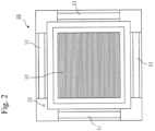
- an indoor unit 50 of an air conditioner is assumed to be a four-way cassette type in which air outlets 51 are provided in four directions.
- the indoor unit 50 is rectangular, and an air inlet 52 is provided in the center portion.
- the four air outlet 51 are provided around the air inlet 52, with air outlet directions shifted by 90 degrees each.
- a light emitter 53 or the like exists outside the air inlet 52 in an area other than the air outlets 51.
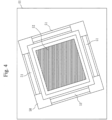
- the image acquisition unit 21 acquires image data 61 obtained by capturing an image of the indoor unit 50 with an imaging device. It is assumed here that the image data 61 indicated in Fig. 4 is acquired. The image acquisition unit 21 writes the image data 61 to the memory 12.
- Step S12 Air outlet detection process
- the air outlet detection unit 22 detects the air outlets 51 from the image data 61 acquired in step S11.
- the air outlet detection unit 22 reads the image data 61 from the memory 12.
- the air outlet detection unit 22 gives the image data 61 as input to an object detection model.
- the object detection model is a machine learning model such as YOLO.
- YOLO is an abbreviation for You Only Look Once.
- the object detection model detects an area of the air outlet 51 that appears in the image data 61.
- the air outlet detection unit 22 acquires the area detected by the object detection model as a detected area 62.
- the detected area is assumed here to be a rectangular area with sides parallel to the vertical axis and sides parallel to the horizontal axis of the image data 61.
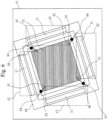
- the indoor unit 50 is the four-way cassette type. Therefore, as illustrated in Fig. 5 , the air outlet detection unit 22 detects the four air outlets 51 provided in four directions. In other words, the detected areas 62 of the four air outlets 51 are individually acquired.
- the object detection model is generated using, as input, pieces of learning data generated by performing at least one of resizing, rotating, and adjusting brightness on pieces of image data obtained by capturing images of the indoor unit 50. This makes it possible to appropriately detect the air outlets 51 even when the image data 61 captured under various distance, orientation, and lighting conditions is given as input.
- the object detection model is generated using, as learning data, pieces of image data obtained by capturing the indoor unit 50 in which the air outlets 51 have different opening degrees. This makes it possible to appropriately detect the air outlets 51 even when the air outlets 51 have different opening degrees.
- the area setting unit 23 sets an area of interest 63 to be a range in which a detection target is to be detected in the image data 61, based on the detected areas 62 of the air outlets detected in step S12.
- a specific example of the detection target is the light emitter 53 or an identification number.
- the area setting unit 23 sets each of the detected areas 62 of the four air outlets as the target detected area 62. As indicated in Fig. 6 , the area setting unit 23 sets, as a reference point 66, the midpoint of a line segment connecting a start point 64 in the target detected area 62 with an end point located nearby among end points 65 in the other detected areas 62. At this time, the area setting unit 23 sets a point on one short side of the target detected area 62 as the start point 64, and sets a point in the other short side of each of the other detected areas 62 as the end point 65.
- Fig. 6 when the detected area 62 is viewed from the center of the air outlet 51, the inner end point of the left short side is the start point 64, and the inner end point of the right short side is the end point 65.
- Each start point 64 is connected with the nearest end point 65, and their midpoint is set as the reference point 66.
- the area setting unit 23 sets a reference figure 67 whose center is the reference point 66.
- the reference figure 67 is a shape such as a rectangle or an ellipse.
- the area setting unit 23 sets the range within the reference figure 67 as the area of interest 63.
- the area setting unit 23 sets the reference figure 67 of a size depending on the size of the detected area 62 of the target air outlet 51.
- the area setting unit 23 sets the reference figure 67 that is shaped depending on the positional relationship of the four detected areas 62.
- the area setting unit 23 sets the reference figure 67 that is rotated depending on the positional relationship of the four detected areas 62.
- the reference figure 67 is resized and rotated in this way because the indoor unit 50 appears differently depending on the imaging distance and direction.
- the imaging distance is the distance between the imaging device and the indoor unit 50.
- the size of the detected area 62 is the area of the detected area 62, or the length of the long side and the length of the short side.
- the size of the reference figure 67 is the area of the reference figure 67, or the length of the long side and the length of the short side or the length of the major axis and the length of the minor axis.
- the area setting unit 23 increases the size of the reference figure 67 as the size of the detected area 62 increases. Specifically, a reference size of the detected area 62 and a standard size of the reference figure 67 are determined in advance. The area setting unit 23 calculates a ratio of the size of the detected area 62 that has been detected to the reference size. Then, the area setting unit 23 adjusts the size of the reference figure 67 by multiplying the standard size of the reference figure 67 by the calculated ratio.
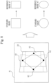
- the area setting unit 23 adjusts the shape of the reference figure 67 based on the positional relationship of the centers of the four detected areas 62. Specifically, a reference shape when the centers of the four air outlets 51 are connected is determined in advance. The reference shape may be considered to be a square. This is because when an image of the indoor unit 50 is captured from directly below, connecting the centers of the four air outlet 51 results in a square. As indicated in Fig. 8 , the area setting unit 23 determines a distortion, relative to the reference shape, of the shape formed by connecting the centers of the four detected areas 62 that have been detected. The area setting unit 23 adjusts the shape of the reference figure 67 by distorting the reference figure 67 according to the determined distortion.
- the shape formed by connecting the centers of the four detected areas 62 is not a square but a rectangle that is squashed laterally. Therefore, if the reference shape of the reference figure 67 is a square, the lateral sides are adjusted to be shorter than the longitudinal sides. If the reference shape of the reference figure 67 is a circle, it is adjusted to an ellipse with the major axis in the longitudinal direction and the minor axis in the lateral direction.
- the area setting unit 23 sets the reference figure 67 that is rotated depending on the positional relationship of the centers of the four detected areas 62. Specifically, a reference shape formed when the centers of the four air outlets 51 are connected is determined in advance. The reference shape may be considered to be a square whose sides are each parallel to the long side or short side of the image data. As indicated in Fig. 9 , the area setting unit 23 determines a rotation angle, relative to the reference shape, of the shape formed by connecting the centers of the four detected areas 62 that have been detected. For example, the area setting unit 23 determines the rotation angle by determining an angle ⁇ , relative to the long side of the image data 61, of one of the sides. The area setting unit 23 rotates the reference figure 67 by the determined rotation angle.
- the area of interest 63 set by the area setting unit 23 is output to an external device or the like that detects the detection target. If the area setting device 10 includes a function for detecting the detection target, the area of interest 63 is output to the function for detecting the detection target.
- the area setting device 10 sets the area of interest 63 based on the detected areas 62 of the air outlets 51.
- the positional relationship of the air outlets 51 and the light emitter 53 or the like, which is the detection target, is roughly determined.
- the air outlets 51 are relatively large in size and easy to detect. Therefore, by setting the area of interest 63 based on the detected areas 62 of the air outlets 51, the area of interest 63 that is appropriate can be set.
- the area of interest 63 By setting the area of interest 63, the area in which the detection target is to be detected is narrowed down. Therefore, it is possible to reduce the likelihood of mistakenly detecting an object with similar characteristics to those of the detection target. As a result, the detection target can be detected with high accuracy.
- the detection target is assumed to be the light emitter 53 such as an LED.
- a terminal such as a smartphone
- operating information of the air conditioner can be transmitted to the terminal. It is conceivable to use the transmitted operating information for maintenance of the air conditioner, for example. Detecting the light emitter 53 with high accuracy using the terminal allows the operating information to be grasped accurately.
- the detection target is assumed to be the identification number of the air outlet 51.
- a terminal such as a smartphone
- the air outlet 51 that needs to be operated can be operated from the terminal. Detecting the identification number with high accuracy using the terminal allows the exact air outlet 51 to be operated.
- Embodiment 1 the functional components are realized by software. However, as Variation 1, the functional components may be realized by hardware. With regard to this Variation 1, differences from Embodiment 1 will be described.
- the area setting device 10 includes an electronic circuit 15 in place of the processor 11, the memory 12, and the storage 13.
- the electronic circuit 15 is a dedicated circuit that realizes the functions of the functional components, the memory 12, and the storage 13.
- the electronic circuit 15 is assumed to be a single circuit, a composite circuit, a programmed processor, a parallel-programmed processor, a logic IC, a GA, an ASIC, or an FPGA.
- GA is an abbreviation for gate array.
- ASIC is an abbreviation for application specific integrated circuit.
- FPGA is an abbreviation for field-programmable gate array.
- the functional components may be realized by one electronic circuit 15, or the functional components may be distributed to and realized by a plurality of electronic circuits 15.
- Each of the processor 11, the memory 12, the storage 13, and the electronic circuit 15 is referred to as processing circuitry. That is, the functions of the functional components are realized by the processing circuitry.
- Embodiment 2 differs from Embodiment 1 in that the area setting device 10 detects the light emitter 53, which is the detection target. In Embodiment 2, this difference will be described, and description of the same aspects will be omitted.
- the area setting device 10 differs from the area setting device 10 illustrated in Fig. 1 in that a light emitter detection unit 24 is included as a functional component.
- the functions of the light emitter detection unit 24 are realized by software or hardware as with the other functional components.
- a procedure for the operation of the area setting device 10 according to Embodiment 2 is equivalent to the area setting method according to Embodiment 2.
- a program that realizes the operation of the area setting device 10 according to Embodiment 2 is equivalent to the area setting program according to Embodiment 2.
- steps S21 to S23 are the same as the processes of steps S11 to S13 in Fig. 3 .
- the light emitter detection unit 24 detects the light emitter 53 from the area of interest 63 set in step S23.
- the detection target is the light emitter 53.
- the light emitter detection unit 24 converts the image into an HSV color space.
- HSV is an abbreviation for hue, saturation, and value.
- the light emitter detection unit 24 extracts, as an object, pixels that fall within the range between a lower limit threshold and an upper limit threshold of HSV pixel values.
- the light emitter detection unit 24 converts each of consecutive pieces of the image data 61 into an HSV color space to generate converted data.
- the light emitter detection unit 24 calculates a difference between pieces of converted data of two chronologically consecutive pieces of the image data 61.
- the light emitter detection unit 24 extracts, as an object, pixels whose difference is greater than a threshold.
- the light emitter detection unit 24 may convert the image into an RGB color space or grayscale, instead of an HSV color space.
- the light emitter detection unit 24 detects an object whose size is smaller than a reference size as the light emitter 53 among detected objects.
- a size is a perimeter or an area. If a plurality of light emitters 53 are detected from the image data 61, the light emitter detection unit 24 detects the light emitter 53 whose center of gravity is located closest to the center of the area of interest 63. If there are a plurality of light emitters 53, a specified number of light emitters 53 are detected sequentially, starting from one closest to the center of the area of interest 63. There are four areas of interest 63 here. Close to the center of the area of interest 63 means close to the center of one of the areas of interest 63.
- the light emitter detection unit 24 may perform pixel expansion processing before object extraction. If the position of the light emitter 53 is included in the detected area 62 of the air outlet 51, the light emitter detection unit 24 may determine that it is not the light emitter 53.
- the area setting device 10 detects the light emitter 53, which is the detection target, from the area of interest 63. This allows the area setting device 10 to acquire operating information of the air conditioner, for example.
- the area setting device 10 may use the operating information to perform some control, or may output the operating information to an external device.
- the area setting device 10 according to Embodiment 2 uses the size to detect the light emitter 53.
- the light emitter 53 is an LED
- the size of the light emitter 53 is relatively small. Therefore, by using the size, the light emitter 53 can be detected with high accuracy.
- the area setting device 10 preferably detects the light emitter 53 that is closer to the center position of the area of interest 63. This increases the likelihood that only the light emitter 53 that is appropriate will be detected even when there are objects with characteristics similar to those of the light emitter 53 in the area of interest 63.
- 10 area setting device
- 11 processor
- 12 memory
- 13 storage
- 14 communication interface
- 15 electronic circuit
- 21 image acquisition unit
- 22 air outlet detection unit
- 23 area setting unit
- 24 light emitter detection unit
- 50 indoor unit
- 52 air inlet
- 53 light emitter
- 61 image data
- 62 detected area
- 63 area of interest
- 64 start point
- 65 end point
- 66 reference point
- 67 reference figure.
Landscapes
- Engineering & Computer Science (AREA)
- Physics & Mathematics (AREA)
- Theoretical Computer Science (AREA)
- General Physics & Mathematics (AREA)
- Multimedia (AREA)
- Computer Vision & Pattern Recognition (AREA)
- Software Systems (AREA)
- Geometry (AREA)
- Mechanical Engineering (AREA)
- General Engineering & Computer Science (AREA)
- Combustion & Propulsion (AREA)
- Chemical & Material Sciences (AREA)
- Air Conditioning Control Device (AREA)
Abstract
Description
- The present disclosure relates to a technology for detecting a light emitter or the like in an indoor unit of an air conditioner.
- An indoor unit of an air conditioner is equipped with a light emitter such as an LED. LED is an abbreviation for light-emitting diode. By reading lighting or blinking of this light emitter using a terminal such as a smartphone, operating information of the air conditioner can be transmitted to the terminal. It is conceivable to use the transmitted operating information for maintenance of the air conditioner, for example.
- Each of air outlets provided in the indoor unit of the air conditioner is assigned an identification number, which is displayed near each of the air outlets. By reading this identification number using a terminal such as a smartphone, a desired one of the air outlets can be operated from the terminal.
- As in these examples, it is effective to appropriately detect the light emitter or the like in the indoor unit of the air conditioner using the terminal. One possible method for detecting the light emitter or the like using the terminal is to detect the light emitter or the like from image data captured by an imaging device.
- However, the method for detecting the light emitter or the like from image data may mistakenly detect an object with similar characteristics to those of the light emitter or the like. Objects with similar characteristics to those of the light emitter include the surface of the housing of the indoor unit illuminated by lighting and a light emitter of a wireless device installed on the ceiling.
-
Patent Literature 1 describes a technology for detecting a traffic light using an in-vehicle camera. InPatent Literature 1, the position and orientation of a vehicle and map information are used to set an area in which a traffic light is likely to appear in image data obtained by the in-vehicle camera. This aims to improve the accuracy of traffic light detection. - Patent Literature 1:
WO 2017/009934 A1 - In
Patent Literature 1, the accuracy of traffic light detection is improved by setting an area in which a traffic light is likely to appear, thereby eliminating sections with similar characteristics to those of the traffic light. However, when the light emitter in the indoor unit of the air conditioner is to be detected, it is not easy to obtain the position and orientation of a person or camera that captures an image and map information of a location where the image is captured. Therefore, it is not realistic to use the technology described inPatent Literature 1 to set an area in which a light emitter or the like is likely to appear. - An object of the present disclosure is to make it possible to detect a light emitter or the like in an indoor unit of an air conditioner with high accuracy.
- An area setting device according to the present disclosure includes
- an air outlet detection unit to detect an air outlet from image data captured of an indoor unit of an air conditioner; and
- an area setting unit to set an area of interest based on a detected area of the air outlet detected by the air outlet detection unit, the area of interest being a range in which a detection target in the indoor unit is to be detected.
- In the present disclosure, an area of interest to be a range in which a detection target in an indoor unit is to be detected is set based on a detected area in which an air outlet of the indoor unit has been detected.
- The air outlet is larger in size than a light emitter or the like and thus can be easily detected. Therefore, it is relatively easy to set the area of interest.
-
-
Fig. 1 is a configuration diagram of anarea setting device 10 according toEmbodiment 1; -
Fig. 2 is a diagram describing anindoor unit 50 of an air conditioner according toEmbodiment 1; -
Fig. 3 is a flowchart illustrating processing by thearea setting device 10 according toEmbodiment 1; -
Fig. 4 is a diagram describingimage data 61 according toEmbodiment 1; -
Fig. 5 is a diagram describing a detectedarea 62 according toEmbodiment 1; -
Fig. 6 is a diagram describing an area setting process according toEmbodiment 1; -
Fig. 7 is a diagram describing the area setting process according toEmbodiment 1; -
Fig. 8 is a diagram describing a setting method 2 for a reference figure 67 according toEmbodiment 1; -
Fig. 9 is a diagram describing a setting method 3 for the reference figure 67 according toEmbodiment 1; -
Fig. 10 is a configuration diagram of thearea setting device 10 according toVariation 1; -
Fig. 11 is a configuration diagram of thearea setting device 10 according to Embodiment 2; and -
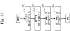
Fig. 12 is a flowchart illustrating a flow of processing by thearea setting device 10 according to Embodiment 2. - Referring to
Fig. 1 , a configuration of thearea setting device 10 according toEmbodiment 1 will be described. - The
area setting device 10 is a computer. - The
area setting device 10 includes hardware such as aprocessor 11, amemory 12, astorage 13, and acommunication interface 14. Theprocessor 11 is connected with other hardware components through signal lines and controls these other hardware components. - The
processor 11 is an IC that performs processing. IC is an abbreviation for integrated circuit. Specific examples of theprocessor 11 are a CPU, a DSP, and a GPU. CPU is an abbreviation for central processing unit. DSP is an abbreviation for digital signal processor. GPU is an abbreviation for graphics processing unit. - The
memory 12 is a storage device to temporarily store data. Specific examples of thememory 12 are an SRAM and a DRAM. SRAM is an abbreviation for static random access memory. DRAM is an abbreviation for dynamic random access memory. - The
storage 13 is a storage device to store data. A specific example of thestorage 13 is an HDD. HDD is an abbreviation for hard disk drive. Alternatively, thestorage 13 may be a portable recording medium such as an SD (registered trademark) memory card, CompactFlash (registered trademark), a NAND flash, a flexible disk, an optical disc, a compact disc, a Blu-ray (registered trademark) disc, or a DVD. SD is an abbreviation for Secure Digital. DVD is an abbreviation for digital versatile disk. - The
communication interface 14 is an interface for communicating with external devices. Specific examples of thecommunication interface 14 are an Ethernet (registered trademark) port, a USB port, and an HDMI (registered trademark) port. USB is an abbreviation for Universal Serial Bus. HDMI is an abbreviation for High-Definition Multimedia Interface. - The
area setting device 10 includes, as functional components, animage acquisition unit 21, an airoutlet detection unit 22, and anarea setting unit 23. The functions of the functional components of thearea setting device 10 are realized by software. - The
storage 13 stores programs that realize the functions of the functional components of thearea setting device 10. These programs are read into thememory 12 by theprocessor 11 and executed by theprocessor 11. This realizes the functions of the functional components of thearea setting device 10. - In
Fig. 1 , only oneprocessor 11 is illustrated. However, there may be a plurality ofprocessors 11, and the plurality ofprocessors 11 may cooperate to execute the programs that realize the functions. - Referring to
Figs. 2 to 9 , the operation of thearea setting device 10 according toEmbodiment 1 will be described. - A procedure for the operation of the
area setting device 10 according toEmbodiment 1 is equivalent to an area setting method according toEmbodiment 1. A program that realizes the operation of thearea setting device 10 according toEmbodiment 1 is equivalent to an area setting program according toEmbodiment 1. - In
Embodiment 1, as illustrated inFig. 2 , anindoor unit 50 of an air conditioner is assumed to be a four-way cassette type in whichair outlets 51 are provided in four directions. Theindoor unit 50 is rectangular, and anair inlet 52 is provided in the center portion. In theindoor unit 50, the fourair outlet 51 are provided around theair inlet 52, with air outlet directions shifted by 90 degrees each. Alight emitter 53 or the like exists outside theair inlet 52 in an area other than theair outlets 51. - Referring to
Fig. 3 , a flow of processing by thearea setting device 10 according toEmbodiment 1 will be described. - The
image acquisition unit 21 acquiresimage data 61 obtained by capturing an image of theindoor unit 50 with an imaging device. It is assumed here that theimage data 61 indicated inFig. 4 is acquired. Theimage acquisition unit 21 writes theimage data 61 to thememory 12. - The air
outlet detection unit 22 detects theair outlets 51 from theimage data 61 acquired in step S11. - Specifically, the air
outlet detection unit 22 reads theimage data 61 from thememory 12. The airoutlet detection unit 22 gives theimage data 61 as input to an object detection model. The object detection model is a machine learning model such as YOLO. YOLO is an abbreviation for You Only Look Once. The object detection model detects an area of theair outlet 51 that appears in theimage data 61. The airoutlet detection unit 22 acquires the area detected by the object detection model as a detectedarea 62. The detected area is assumed here to be a rectangular area with sides parallel to the vertical axis and sides parallel to the horizontal axis of theimage data 61. - In
Embodiment 1, theindoor unit 50 is the four-way cassette type. Therefore, as illustrated inFig. 5 , the airoutlet detection unit 22 detects the fourair outlets 51 provided in four directions. In other words, the detectedareas 62 of the fourair outlets 51 are individually acquired. - The object detection model is generated using, as input, pieces of learning data generated by performing at least one of resizing, rotating, and adjusting brightness on pieces of image data obtained by capturing images of the
indoor unit 50. This makes it possible to appropriately detect theair outlets 51 even when theimage data 61 captured under various distance, orientation, and lighting conditions is given as input. - In addition, the object detection model is generated using, as learning data, pieces of image data obtained by capturing the
indoor unit 50 in which theair outlets 51 have different opening degrees. This makes it possible to appropriately detect theair outlets 51 even when theair outlets 51 have different opening degrees. - The
area setting unit 23 sets an area ofinterest 63 to be a range in which a detection target is to be detected in theimage data 61, based on the detectedareas 62 of the air outlets detected in step S12. A specific example of the detection target is thelight emitter 53 or an identification number. - Referring to
Figs. 6 and7 , this will be described specifically. - The
area setting unit 23 sets each of the detectedareas 62 of the four air outlets as the target detectedarea 62. As indicated inFig. 6 , thearea setting unit 23 sets, as areference point 66, the midpoint of a line segment connecting astart point 64 in the target detectedarea 62 with an end point located nearby amongend points 65 in the other detectedareas 62. At this time, thearea setting unit 23 sets a point on one short side of the target detectedarea 62 as thestart point 64, and sets a point in the other short side of each of the other detectedareas 62 as theend point 65. - In
Fig. 6 , when the detectedarea 62 is viewed from the center of theair outlet 51, the inner end point of the left short side is thestart point 64, and the inner end point of the right short side is theend point 65. Eachstart point 64 is connected with thenearest end point 65, and their midpoint is set as thereference point 66. - As indicated in
Fig. 7 , thearea setting unit 23 sets a reference figure 67 whose center is thereference point 66. The reference figure 67 is a shape such as a rectangle or an ellipse. Thearea setting unit 23 sets the range within the reference figure 67 as the area ofinterest 63. - When setting the reference figure 67, the
area setting unit 23 sets the reference figure 67 of a size depending on the size of the detectedarea 62 of thetarget air outlet 51. Thearea setting unit 23 sets the reference figure 67 that is shaped depending on the positional relationship of the four detectedareas 62. Thearea setting unit 23 sets the reference figure 67 that is rotated depending on the positional relationship of the four detectedareas 62. The reference figure 67 is resized and rotated in this way because theindoor unit 50 appears differently depending on the imaging distance and direction. The imaging distance is the distance between the imaging device and theindoor unit 50. - The size of the detected
area 62 is the area of the detectedarea 62, or the length of the long side and the length of the short side. Similarly, the size of the reference figure 67 is the area of the reference figure 67, or the length of the long side and the length of the short side or the length of the major axis and the length of the minor axis. - Setting methods for the reference figure 67 will be described specifically.
- The
area setting unit 23 increases the size of the reference figure 67 as the size of the detectedarea 62 increases. Specifically, a reference size of the detectedarea 62 and a standard size of the reference figure 67 are determined in advance. Thearea setting unit 23 calculates a ratio of the size of the detectedarea 62 that has been detected to the reference size. Then, thearea setting unit 23 adjusts the size of the reference figure 67 by multiplying the standard size of the reference figure 67 by the calculated ratio. - The
area setting unit 23 adjusts the shape of the reference figure 67 based on the positional relationship of the centers of the four detectedareas 62. Specifically, a reference shape when the centers of the fourair outlets 51 are connected is determined in advance. The reference shape may be considered to be a square. This is because when an image of theindoor unit 50 is captured from directly below, connecting the centers of the fourair outlet 51 results in a square. As indicated inFig. 8 , thearea setting unit 23 determines a distortion, relative to the reference shape, of the shape formed by connecting the centers of the four detectedareas 62 that have been detected. Thearea setting unit 23 adjusts the shape of the reference figure 67 by distorting the reference figure 67 according to the determined distortion. - In
Fig. 8 , the shape formed by connecting the centers of the four detectedareas 62 is not a square but a rectangle that is squashed laterally. Therefore, if the reference shape of the reference figure 67 is a square, the lateral sides are adjusted to be shorter than the longitudinal sides. If the reference shape of the reference figure 67 is a circle, it is adjusted to an ellipse with the major axis in the longitudinal direction and the minor axis in the lateral direction. - The
area setting unit 23 sets the reference figure 67 that is rotated depending on the positional relationship of the centers of the four detectedareas 62. Specifically, a reference shape formed when the centers of the fourair outlets 51 are connected is determined in advance. The reference shape may be considered to be a square whose sides are each parallel to the long side or short side of the image data. As indicated inFig. 9 , thearea setting unit 23 determines a rotation angle, relative to the reference shape, of the shape formed by connecting the centers of the four detectedareas 62 that have been detected. For example, thearea setting unit 23 determines the rotation angle by determining an angle θ, relative to the long side of theimage data 61, of one of the sides. Thearea setting unit 23 rotates the reference figure 67 by the determined rotation angle. - The area of
interest 63 set by thearea setting unit 23 is output to an external device or the like that detects the detection target. If thearea setting device 10 includes a function for detecting the detection target, the area ofinterest 63 is output to the function for detecting the detection target. - As described above, the
area setting device 10 according toEmbodiment 1 sets the area ofinterest 63 based on the detectedareas 62 of theair outlets 51. In theindoor unit 50 of the air conditioner of a four cassette type, the positional relationship of theair outlets 51 and thelight emitter 53 or the like, which is the detection target, is roughly determined. In addition, theair outlets 51 are relatively large in size and easy to detect. Therefore, by setting the area ofinterest 63 based on the detectedareas 62 of theair outlets 51, the area ofinterest 63 that is appropriate can be set. - By setting the area of
interest 63, the area in which the detection target is to be detected is narrowed down. Therefore, it is possible to reduce the likelihood of mistakenly detecting an object with similar characteristics to those of the detection target. As a result, the detection target can be detected with high accuracy. - The detection target is assumed to be the
light emitter 53 such as an LED. In this case, by reading lighting or blinking of thelight emitter 53 using a terminal such as a smartphone, operating information of the air conditioner can be transmitted to the terminal. It is conceivable to use the transmitted operating information for maintenance of the air conditioner, for example. Detecting thelight emitter 53 with high accuracy using the terminal allows the operating information to be grasped accurately. - The detection target is assumed to be the identification number of the
air outlet 51. In this case, by reading the identification number using a terminal such as a smartphone, theair outlet 51 that needs to be operated can be operated from the terminal. Detecting the identification number with high accuracy using the terminal allows theexact air outlet 51 to be operated. - In
Embodiment 1, the functional components are realized by software. However, asVariation 1, the functional components may be realized by hardware. With regard to thisVariation 1, differences fromEmbodiment 1 will be described. - Referring to
Fig. 10 , a configuration of thearea setting device 10 according toVariation 1 will be described. - When the functional components are realized by hardware, the
area setting device 10 includes anelectronic circuit 15 in place of theprocessor 11, thememory 12, and thestorage 13. Theelectronic circuit 15 is a dedicated circuit that realizes the functions of the functional components, thememory 12, and thestorage 13. - The
electronic circuit 15 is assumed to be a single circuit, a composite circuit, a programmed processor, a parallel-programmed processor, a logic IC, a GA, an ASIC, or an FPGA. GA is an abbreviation for gate array. ASIC is an abbreviation for application specific integrated circuit. FPGA is an abbreviation for field-programmable gate array. - The functional components may be realized by one
electronic circuit 15, or the functional components may be distributed to and realized by a plurality ofelectronic circuits 15. - As Variation 2, some of the functional components may be realized by hardware, and the rest of the functional components may be realized by software.
- Each of the
processor 11, thememory 12, thestorage 13, and theelectronic circuit 15 is referred to as processing circuitry. That is, the functions of the functional components are realized by the processing circuitry. - Embodiment 2 differs from
Embodiment 1 in that thearea setting device 10 detects thelight emitter 53, which is the detection target. In Embodiment 2, this difference will be described, and description of the same aspects will be omitted. - Referring to
Fig. 11 , a configuration of thearea setting device 10 according to Embodiment 2 will be described. - The
area setting device 10 differs from thearea setting device 10 illustrated inFig. 1 in that a lightemitter detection unit 24 is included as a functional component. The functions of the lightemitter detection unit 24 are realized by software or hardware as with the other functional components. - Referring to
Fig. 12 , the operation of thearea setting device 10 according to Embodiment 2 will be described. - A procedure for the operation of the
area setting device 10 according to Embodiment 2 is equivalent to the area setting method according to Embodiment 2. A program that realizes the operation of thearea setting device 10 according to Embodiment 2 is equivalent to the area setting program according to Embodiment 2. - Referring to
Fig. 12 , a flow of processing by thearea setting device 10 according to Embodiment 2 will be described. - The processes of steps S21 to S23 are the same as the processes of steps S11 to S13 in
Fig. 3 . - The light
emitter detection unit 24 detects thelight emitter 53 from the area ofinterest 63 set in step S23. In Embodiment 2, the detection target is thelight emitter 53. - Specifically, (1) when the
light emitter 53 in a lit state is to be detected, the lightemitter detection unit 24 converts the image into an HSV color space. HSV is an abbreviation for hue, saturation, and value. The lightemitter detection unit 24 extracts, as an object, pixels that fall within the range between a lower limit threshold and an upper limit threshold of HSV pixel values. (2) When thelight emitter 53 in a blinking state is to be detected, the lightemitter detection unit 24 converts each of consecutive pieces of theimage data 61 into an HSV color space to generate converted data. The lightemitter detection unit 24 calculates a difference between pieces of converted data of two chronologically consecutive pieces of theimage data 61. The lightemitter detection unit 24 extracts, as an object, pixels whose difference is greater than a threshold. When thelight emitter 53 in a blinking state is to be detected, the lightemitter detection unit 24 may convert the image into an RGB color space or grayscale, instead of an HSV color space. - The light
emitter detection unit 24 detects an object whose size is smaller than a reference size as thelight emitter 53 among detected objects. A size is a perimeter or an area. If a plurality oflight emitters 53 are detected from theimage data 61, the lightemitter detection unit 24 detects thelight emitter 53 whose center of gravity is located closest to the center of the area ofinterest 63. If there are a plurality oflight emitters 53, a specified number oflight emitters 53 are detected sequentially, starting from one closest to the center of the area ofinterest 63. There are four areas ofinterest 63 here. Close to the center of the area ofinterest 63 means close to the center of one of the areas ofinterest 63. - If the
light emitters 53 close to each other need to be extracted as one object, the lightemitter detection unit 24 may perform pixel expansion processing before object extraction. If the position of thelight emitter 53 is included in the detectedarea 62 of theair outlet 51, the lightemitter detection unit 24 may determine that it is not thelight emitter 53. - As described above, the
area setting device 10 according to Embodiment 2 detects thelight emitter 53, which is the detection target, from the area ofinterest 63. This allows thearea setting device 10 to acquire operating information of the air conditioner, for example. Thearea setting device 10 may use the operating information to perform some control, or may output the operating information to an external device. - The
area setting device 10 according to Embodiment 2 uses the size to detect thelight emitter 53. When thelight emitter 53 is an LED, the size of thelight emitter 53 is relatively small. Therefore, by using the size, thelight emitter 53 can be detected with high accuracy. - The
area setting device 10 according to Embodiment 2 preferably detects thelight emitter 53 that is closer to the center position of the area ofinterest 63. This increases the likelihood that only thelight emitter 53 that is appropriate will be detected even when there are objects with characteristics similar to those of thelight emitter 53 in the area ofinterest 63. - "Unit" in the above description may be interpreted as "circuit", "step", "procedure", "process", or "processing circuitry".
- The embodiments and variations of the present disclosure have been described above. Two or more of these embodiments and variations may be implemented in combination. Alternatively, one of them or two or more of them may be partially implemented. The present disclosure is not limited to the above embodiments and variations, and various modifications can be made as necessary.
- 10: area setting device, 11: processor, 12: memory, 13: storage, 14: communication interface, 15: electronic circuit, 21: image acquisition unit, 22: air outlet detection unit, 23: area setting unit, 24: light emitter detection unit, 50: indoor unit, 51: air outlet, 52: air inlet, 53: light emitter, 61: image data, 62: detected area, 63: area of interest, 64: start point, 65: end point, 66: reference point, 67: reference figure.
Claims (13)
- An area setting device comprising:an air outlet detection unit to detect an air outlet from image data captured of an indoor unit of an air conditioner; andan area setting unit to set an area of interest based on a detected area of the air outlet detected by the air outlet detection unit, the area of interest being a range in which a detection target is to be detected in the image data.
- The area setting device according to claim 1,wherein the indoor unit is a four-way cassette type in which air outlets are provided in four directions,wherein the air outlet detection unit detects four air outlets provided in the four directions, andwherein the area setting unit treats each of detected areas of the four air outlets as a target detected area, and sets the area of interest based on a point on a line segment connecting a start point in the target detected area with an end point located nearby among end points in other ones of the detected areas.
- The area setting device according to claim 2,
wherein the area setting unit sets a reference figure whose center is a point on the line segment, and sets a range within the reference figure as the area of interest. - The area setting device according to claim 3,
wherein the area setting unit sets the reference figure of a size depending on a size of the target detected area of an air outlet. - The area setting device according to claim 3 or 4,
wherein the area setting unit sets the reference figure whose shape depends on a positional relationship of the detected areas of the four air outlets. - The area setting device according to any one of claims 3 to 5,
wherein the area setting unit sets the reference figure that is rotated depending on a positional relationship of the detected areas of the four air outlets. - The area setting device according to any one of claims 2 to 6,wherein the detected area is a rectangle, andwherein the area setting unit treats a point on one short side in the target detected area as a start point, and treats a point on the other short side in each of the other detected areas as an end point.
- The area setting device according to any one of claims 1 to 7,
wherein the air outlet detection unit detects an air outlet from image data captured of the indoor unit using an object detection model that takes, as input, image data and detects an air outlet, the object detection model being generated using, as input, learning data generated by performing at least one of resizing, rotating, and adjusting brightness on image data of an indoor unit. - The area setting device according to any one of claims 1 to 7,
wherein the air outlet detection unit detects an air outlet from image data captured of the indoor unit using an object detection model that takes, as input, image data and detects an air outlet, the object detection model being generated using, as input, learning data including pieces of image data of an indoor unit in each of which an opening degree of the air outlet is different. - The area setting device according to any one of claims 1 to 9, further comprising
a light emitter detection unit to detect a light emitter whose size is smaller than a reference size from the area of interest set by the area setting unit. - The area setting device according to claim 10,
wherein the light emitter detection unit detects a light emitter located close to a center of the area of interest among light emitters whose size is smaller than the reference size. - An area setting method comprising:detecting an air outlet from image data captured of an indoor unit of an air conditioner, by a computer; andsetting an area of interest based on a detected area of the air outlet that has been detected, the area of interest being a range in which a detection target is to be detected in the image data, by the computer.
- An area setting program that causes a computer to function as an area setting device to perform:an air outlet detection process of detecting an air outlet from image data captured of an indoor unit of an air conditioner; andan area setting process of setting an area of interest based on a detected area of the air outlet detected by the air outlet detection process, the area of interest being a range in which a detection target is to be detected in the image data.
Applications Claiming Priority (1)
| Application Number | Priority Date | Filing Date | Title |
|---|---|---|---|
| PCT/JP2022/033210 WO2024052949A1 (en) | 2022-09-05 | 2022-09-05 | Region setting device, region setting method, and region setting program |
Publications (2)
| Publication Number | Publication Date |
|---|---|
| EP4553397A1 true EP4553397A1 (en) | 2025-05-14 |
| EP4553397A4 EP4553397A4 (en) | 2025-09-03 |
Family
ID=90192331
Family Applications (1)
| Application Number | Title | Priority Date | Filing Date |
|---|---|---|---|
| EP22958033.7A Pending EP4553397A4 (en) | 2022-09-05 | 2022-09-05 | RANGE SETTING DEVICE, RANGE SETTING METHOD AND RANGE SETTING PROGRAM |
Country Status (5)
| Country | Link |
|---|---|
| US (1) | US20250131682A1 (en) |
| EP (1) | EP4553397A4 (en) |
| JP (1) | JP7584715B2 (en) |
| CN (1) | CN119768644A (en) |
| WO (1) | WO2024052949A1 (en) |
Family Cites Families (8)
| Publication number | Priority date | Publication date | Assignee | Title |
|---|---|---|---|---|
| JP4803296B2 (en) * | 2009-10-30 | 2011-10-26 | ダイキン工業株式会社 | Indoor unit and air conditioner equipped with the same |
| JP5673720B2 (en) * | 2013-04-01 | 2015-02-18 | ダイキン工業株式会社 | AIR CONDITIONER OPERATION SYSTEM AND OPERATION METHOD |
| MX367068B (en) | 2015-07-13 | 2019-08-05 | Nissan Motor | Traffic light recognition device and traffic light recognition method. |
| EP3457042A4 (en) * | 2016-05-11 | 2019-05-01 | Mitsubishi Electric Corporation | AIR CONDITIONING VISUALIZATION SYSTEM |
| WO2018042621A1 (en) * | 2016-09-02 | 2018-03-08 | 三菱電機株式会社 | Air conditioning system |
| JP6983309B2 (en) * | 2018-04-16 | 2021-12-17 | 三菱電機株式会社 | Obstacle detection device, automatic braking device using obstacle detection device, obstacle detection method, and automatic braking method using obstacle detection method |
| JP6972376B2 (en) * | 2018-10-26 | 2021-11-24 | 三菱電機株式会社 | Installation position identification device, air conditioning system, installation position identification method, and program |
| WO2021240625A1 (en) * | 2020-05-26 | 2021-12-02 | 三菱電機株式会社 | Air-conditioning operation terminal, air-conditioning operation program, and air conditioning system |
-
2022
- 2022-09-05 CN CN202280099583.0A patent/CN119768644A/en active Pending
- 2022-09-05 JP JP2024540599A patent/JP7584715B2/en active Active
- 2022-09-05 EP EP22958033.7A patent/EP4553397A4/en active Pending
- 2022-09-05 WO PCT/JP2022/033210 patent/WO2024052949A1/en not_active Ceased
-
2025
- 2025-01-02 US US19/007,892 patent/US20250131682A1/en active Pending
Also Published As
| Publication number | Publication date |
|---|---|
| CN119768644A (en) | 2025-04-04 |
| EP4553397A4 (en) | 2025-09-03 |
| JP7584715B2 (en) | 2024-11-15 |
| US20250131682A1 (en) | 2025-04-24 |
| JPWO2024052949A1 (en) | 2024-03-14 |
| WO2024052949A1 (en) | 2024-03-14 |
Similar Documents
| Publication | Publication Date | Title |
|---|---|---|
| CN108701376B (en) | Recognition-Based Object Segmentation for 3D Images | |
| JP6230751B1 (en) | Object detection apparatus and object detection method | |
| CN111435438A (en) | Graphical fiducial marker recognition for augmented reality, virtual reality and robotics | |
| US10163027B2 (en) | Apparatus for and method of processing image based on object region | |
| US20220198679A1 (en) | Object detection device, learning device and computer readable medium | |
| US20170228606A1 (en) | Information processing apparatus, information processing method, and recording medium | |
| US20170091577A1 (en) | Augmented reality processing system and method thereof | |
| KR102595787B1 (en) | Electronic device and control method thereof | |
| US9667880B2 (en) | Activating flash for capturing images with text | |
| CN111325798A (en) | Camera model correction method, device, AR implementation device and readable storage medium | |
| JP6742736B2 (en) | Lighting color determination device for traffic light and lighting color determination method for traffic light | |
| JP2021096652A (en) | Image identification device, method, and program | |
| EP4553397A1 (en) | Region setting device, region setting method, and region setting program | |
| CN115620185B (en) | A method, device, and terminal equipment for identifying the illumination status of an indicator light. | |
| CN112580516A (en) | Road scene recognition method, device, equipment and storage medium | |
| CN113869292B (en) | Target detection method, device and equipment for automatic driving | |
| US10652436B2 (en) | Image processing apparatus, image processing method, and storage medium | |
| CN114067291A (en) | Signal lamp detection method and device | |
| JP6825299B2 (en) | Information processing equipment, information processing methods and programs | |
| JP2020194281A (en) | Reading system, reading method, program, storage medium, and mobile body | |
| CN116558718A (en) | Indoor water leakage detection method, device, terminal equipment and readable storage medium | |
| JP6034713B2 (en) | Outside environment recognition device and outside environment recognition method | |
| KR102248673B1 (en) | Method for identificating traffic lights, device and program using the same | |
| JP2018055591A (en) | Information processing apparatus, information processing method, and program | |
| US12387504B2 (en) | Image processing apparatus |
Legal Events
| Date | Code | Title | Description |
|---|---|---|---|
| STAA | Information on the status of an ep patent application or granted ep patent |
Free format text: STATUS: THE INTERNATIONAL PUBLICATION HAS BEEN MADE |
|
| PUAI | Public reference made under article 153(3) epc to a published international application that has entered the european phase |
Free format text: ORIGINAL CODE: 0009012 |
|
| STAA | Information on the status of an ep patent application or granted ep patent |
Free format text: STATUS: REQUEST FOR EXAMINATION WAS MADE |
|
| 17P | Request for examination filed |
Effective date: 20250203 |
|
| AK | Designated contracting states |
Kind code of ref document: A1 Designated state(s): AL AT BE BG CH CY CZ DE DK EE ES FI FR GB GR HR HU IE IS IT LI LT LU LV MC MK MT NL NO PL PT RO RS SE SI SK SM TR |
|
| A4 | Supplementary search report drawn up and despatched |
Effective date: 20250730 |
|
| RIC1 | Information provided on ipc code assigned before grant |
Ipc: F24F 11/52 20180101AFI20250725BHEP Ipc: F24F 11/54 20180101ALI20250725BHEP Ipc: F24F 11/64 20180101ALI20250725BHEP Ipc: G06V 10/25 20220101ALI20250725BHEP Ipc: F24F 11/72 20180101ALI20250725BHEP |
|
| DAV | Request for validation of the european patent (deleted) | ||
| DAX | Request for extension of the european patent (deleted) | ||
| STAA | Information on the status of an ep patent application or granted ep patent |
Free format text: STATUS: EXAMINATION IS IN PROGRESS |
|
| 17Q | First examination report despatched |
Effective date: 20260205 |