EP4553396A1 - Indoor unit and air conditioning device comprising same - Google Patents
Indoor unit and air conditioning device comprising same Download PDFInfo
- Publication number
- EP4553396A1 EP4553396A1 EP24731227.5A EP24731227A EP4553396A1 EP 4553396 A1 EP4553396 A1 EP 4553396A1 EP 24731227 A EP24731227 A EP 24731227A EP 4553396 A1 EP4553396 A1 EP 4553396A1
- Authority
- EP
- European Patent Office
- Prior art keywords
- refrigerant
- space
- indoor unit
- passage
- indoor
- Prior art date
- Legal status (The legal status is an assumption and is not a legal conclusion. Google has not performed a legal analysis and makes no representation as to the accuracy of the status listed.)
- Pending
Links
Images


Classifications
-
- F—MECHANICAL ENGINEERING; LIGHTING; HEATING; WEAPONS; BLASTING
- F24—HEATING; RANGES; VENTILATING
- F24F—AIR-CONDITIONING; AIR-HUMIDIFICATION; VENTILATION; USE OF AIR CURRENTS FOR SCREENING
- F24F1/00—Room units for air-conditioning, e.g. separate or self-contained units or units receiving primary air from a central station
- F24F1/0007—Indoor units, e.g. fan coil units
- F24F1/0043—Indoor units, e.g. fan coil units characterised by mounting arrangements
- F24F1/0047—Indoor units, e.g. fan coil units characterised by mounting arrangements mounted in the ceiling or at the ceiling
-
- F—MECHANICAL ENGINEERING; LIGHTING; HEATING; WEAPONS; BLASTING
- F24—HEATING; RANGES; VENTILATING
- F24F—AIR-CONDITIONING; AIR-HUMIDIFICATION; VENTILATION; USE OF AIR CURRENTS FOR SCREENING
- F24F1/00—Room units for air-conditioning, e.g. separate or self-contained units or units receiving primary air from a central station
- F24F1/0007—Indoor units, e.g. fan coil units
- F24F1/0018—Indoor units, e.g. fan coil units characterised by fans
-
- F—MECHANICAL ENGINEERING; LIGHTING; HEATING; WEAPONS; BLASTING
- F24—HEATING; RANGES; VENTILATING
- F24F—AIR-CONDITIONING; AIR-HUMIDIFICATION; VENTILATION; USE OF AIR CURRENTS FOR SCREENING
- F24F11/00—Control or safety arrangements
- F24F11/30—Control or safety arrangements for purposes related to the operation of the system, e.g. for safety or monitoring
- F24F11/32—Responding to malfunctions or emergencies
- F24F11/36—Responding to malfunctions or emergencies to leakage of heat-exchange fluid
-
- F—MECHANICAL ENGINEERING; LIGHTING; HEATING; WEAPONS; BLASTING
- F24—HEATING; RANGES; VENTILATING
- F24F—AIR-CONDITIONING; AIR-HUMIDIFICATION; VENTILATION; USE OF AIR CURRENTS FOR SCREENING
- F24F13/00—Details common to, or for air-conditioning, air-humidification, ventilation or use of air currents for screening
- F24F13/08—Air-flow control members, e.g. louvres, grilles, flaps or guide plates
-
- F—MECHANICAL ENGINEERING; LIGHTING; HEATING; WEAPONS; BLASTING
- F24—HEATING; RANGES; VENTILATING
- F24F—AIR-CONDITIONING; AIR-HUMIDIFICATION; VENTILATION; USE OF AIR CURRENTS FOR SCREENING
- F24F13/00—Details common to, or for air-conditioning, air-humidification, ventilation or use of air currents for screening
- F24F13/20—Casings or covers
-
- F—MECHANICAL ENGINEERING; LIGHTING; HEATING; WEAPONS; BLASTING
- F24—HEATING; RANGES; VENTILATING
- F24F—AIR-CONDITIONING; AIR-HUMIDIFICATION; VENTILATION; USE OF AIR CURRENTS FOR SCREENING
- F24F8/00—Treatment, e.g. purification, of air supplied to human living or working spaces otherwise than by heating, cooling, humidifying or drying
- F24F8/10—Treatment, e.g. purification, of air supplied to human living or working spaces otherwise than by heating, cooling, humidifying or drying by separation, e.g. by filtering
- F24F8/108—Treatment, e.g. purification, of air supplied to human living or working spaces otherwise than by heating, cooling, humidifying or drying by separation, e.g. by filtering using dry filter elements
-
- F—MECHANICAL ENGINEERING; LIGHTING; HEATING; WEAPONS; BLASTING
- F24—HEATING; RANGES; VENTILATING
- F24F—AIR-CONDITIONING; AIR-HUMIDIFICATION; VENTILATION; USE OF AIR CURRENTS FOR SCREENING
- F24F13/00—Details common to, or for air-conditioning, air-humidification, ventilation or use of air currents for screening
- F24F13/02—Ducting arrangements
- F24F13/06—Outlets for directing or distributing air into rooms or spaces, e.g. ceiling air diffuser
- F24F2013/0616—Outlets that have intake openings
-
- F—MECHANICAL ENGINEERING; LIGHTING; HEATING; WEAPONS; BLASTING
- F24—HEATING; RANGES; VENTILATING
- F24F—AIR-CONDITIONING; AIR-HUMIDIFICATION; VENTILATION; USE OF AIR CURRENTS FOR SCREENING
- F24F2221/00—Details or features not otherwise provided for
- F24F2221/14—Details or features not otherwise provided for mounted on the ceiling
Definitions
- the present disclosure relates to an air conditioner and particularly relates to an indoor unit including a refrigerant sensor configured to detect a refrigerant leaked from a refrigerant circuit.
- Patent Literature 1 discloses an indoor unit to be embedded in a ceiling.
- This indoor unit includes a refrigerant sensor configured to detect a leaked refrigerant.
- the refrigerant sensor is disposed near a suction port of the indoor unit, and detects a refrigerant component contained in the air sucked into the indoor unit.
- This refrigerant component is the refrigerant that has leaked from the refrigerant circuit, then come out to the indoor space, and been diluted with the indoor air.
- the refrigerant leaked from a refrigerant circuit disposed outside a bell mouth needs to reach a refrigerant sensor disposed inside the bell mouth.
- the refrigerant leaked from the refrigerant circuit needs to flow over the height of the bell mouth to reach the refrigerant sensor. It takes time for detection also in this case.
- An indoor unit is of a ceiling embedded type.
- the indoor unit includes a case, a heat exchanger, a fan, an air guide member, a passage, and a refrigerant sensor.
- the case has a suction port.
- the fan sucks indoor air via the suction port and sends the indoor air thus sucked to the heat exchanger.
- the air guide member guides the indoor air sucked into the fan.
- the air guide member divides an internal space of the case into a first space and a second space.
- the second space is disposed downstream of the first space in an air flow.
- the passage is provided in the air guide member.
- the passage allows a refrigerant to pass through from the second space to the first space.
- the refrigerant sensor is disposed closer to the first space in the passage.
- the refrigerant sensor is configured to detect the refrigerant having passed through the passage.
- a refrigerant leaked around the heat exchanger passes through the passage to reach the refrigerant sensor. Accordingly, the leaked refrigerant to be detected does not need to flow over an upper end of the air guide member. This achieves quick detection of refrigerant leakage.
- the refrigerant sensor is positioned to be easily replaced, thereby also facilitating maintenance.
- An indoor unit according to a second aspect is the indoor unit according to the first aspect, in which the refrigerant sensor is disposed to be directed upward in a lower portion of the passage.
- An indoor unit is the indoor unit according to the first or second aspect, and further includes a drain pan.
- the drain pan is disposed adjacent to the air guide member.
- the drain pan is disposed to face a lower end of the heat exchanger.
- the drain pan has a bottom positioned lower than an upper end of the passage.
- the bottom of the drain pan is positioned lower than the passage. Drain water leaking from around the bottom of a cracked drain pan is thus less likely to reach the passage. This inhibits the drain water from damaging the refrigerant sensor.
- An indoor unit according to a fourth aspect is the indoor unit according to any one of the first to third aspects, and further includes a sealing material.
- the sealing material seals a gap between the passage and the refrigerant sensor.
- the gap between the passage and the refrigerant sensor is sealed in this configuration. This inhibits leakage of conditioned air to keep air conditioning efficiency.
- An indoor unit according to a fifth aspect is the indoor unit according to any one of the first to fourth aspects, and further includes a filter.
- the filter is provided at the suction port.
- An air conditioner according to a sixth aspect includes the indoor unit according to any one of the first to fifth aspects.
- This configuration achieves quick detection of refrigerant leakage in the air conditioner.
- the refrigerant sensor is positioned to be easily replaced, thereby facilitating maintenance of the air conditioner.
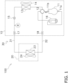
- FIG. 1 depicts an air conditioner 100 according to an embodiment.
- the air conditioner 100 is constituted by an outdoor unit 10, an indoor unit 20, and a refrigerant pipe group 30 connecting the outdoor unit 10 and the indoor unit 20.
- the air conditioner 100 includes a refrigerant circuit for circulation of a refrigerant R.
- the outdoor unit 10 includes, as components of the refrigerant circuit, a compressor 11, a four-way switching valve 12, an outdoor heat exchanger 13, an outdoor expansion valve 15, an accumulator 16, a liquid shutoff valve 17, and a gas shutoff valve 18.
- the indoor unit 20 includes an indoor heat exchanger 23 as a component of the refrigerant circuit.
- the refrigerant pipe group 30 includes a liquid connection pipe 31 and a gas connection pipe 32 as components of the refrigerant circuit.
- a cooling operation is an operation in which the air conditioner 100 provides a user with cold heat.
- the compressor 11 sucks a low-pressure gas refrigerant from an suction tube 11a and compresses it to generate a high-pressure gas refrigerant to be discharged from a discharge tube 11b.
- the four-way switching valve 12 achieves connection indicated by solid lines.
- the outdoor heat exchanger 13 condenses the high-pressure gas refrigerant to generate a high-pressure liquid refrigerant.
- An outdoor fan 14 promotes heat exchange between the refrigerant and the air in the outdoor heat exchanger 13.
- the outdoor expansion valve 15 decompresses the high-pressure liquid refrigerant to generate a low-pressure gas-liquid two-phase refrigerant.
- the low-pressure gas-liquid two-phase refrigerant passes through the liquid shutoff valve 17 and the liquid connection pipe 31 to reach the indoor heat exchanger 23.
- the indoor heat exchanger 23 evaporates the gas-liquid two-phase refrigerant to generate a low-pressure gas refrigerant, generating hot heat to be supplied to a user during this process.
- An indoor fan 24 promotes heat exchange between the refrigerant and the air in the indoor heat exchanger 23, and delivers, to a user, cold heat in the form of cool air.
- the low-pressure gas refrigerant passes through the gas connection pipe 32, the gas shutoff valve 18, and the four-way switching valve 12 to reach the accumulator 16.
- the accumulator 16 separates a fluid component mixed in the low-pressure gas refrigerant and reserves the fluid component.
- the low-pressure gas refrigerant flowing out of the accumulator 16 is sucked from the suction tube 11a by the compressor 11.
- the compressor 11 sucks a low-pressure gas refrigerant from an suction tube 11a and compresses it to generate a high-pressure gas refrigerant to be discharged from a discharge tube 11b.
- the four-way switching valve 12 achieves connection indicated by broken lines.
- the high-pressure gas refrigerant passes through the four-way switching valve 12, the gas shutoff valve 18, and the gas connection pipe 32 to reach the indoor heat exchanger 23.
- the indoor heat exchanger 23 condenses the high-pressure gas refrigerant to generate a high-pressure liquid refrigerant, generating hot heat to be supplied to a user during this process.
- the indoor fan 24 promotes heat exchange between the refrigerant and the air in the indoor heat exchanger 23, and delivers, to a user, hot heat in the form of warm air.
- the high-pressure liquid refrigerant passes through the liquid connection pipe 31 and the liquid shutoff valve 17 to reach the outdoor expansion valve 15.
- the outdoor expansion valve 15 decompresses the high-pressure liquid refrigerant to generate a low-pressure gas-liquid two-phase refrigerant.
- the outdoor heat exchanger 13 evaporates the low-pressure gas-liquid two-phase refrigerant to generate a low-pressure gas refrigerant.
- An outdoor fan 14 promotes heat exchange between the refrigerant and the air in the outdoor heat exchanger 13.
- the low-pressure gas refrigerant reaches the accumulator 16 via the four-way switching valve 12.
- the accumulator 16 separates a fluid component mixed in the low-pressure gas refrigerant and reserves the fluid component.
- the low-pressure gas refrigerant flowing out of the accumulator 16 is sucked from the suction tube 11a by the compressor 11.
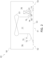
- FIG. 2 is a schematic view of a structure of the indoor unit 20.
- the indoor unit 20 is designed to be embedded in a ceiling.
- the indoor unit 20 includes a case 50, the indoor heat exchanger 23, the indoor fan 24, an air guide member 70, a refrigerant sensor 60, and a drain pan 73.
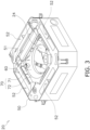
- FIG. 3 is a perspective view of the indoor unit 20. This figure depicts, in an upper side, a lower surface of the indoor unit 20. This figure depicts, in a lower side, an upper surface of the indoor unit 20 as a portion to be embedded in a ceiling.
- the case 50 accommodates components constituting the indoor unit 20 including the indoor heat exchanger 23 and the indoor fan 24.
- the case 50 is provided with a single suction port 51 for intake of air from an indoor space, and four blow-out ports 52 for supply of conditioned air into the indoor space.
- the suction port 51 is provided with a filter 53 configured to remove dust or dirt from intake air.
- FIG. 3 does not depict the filter 53.
- the indoor heat exchanger 23 depicted in FIG. 2 functions as an evaporator for the refrigerant R during the cooling operation and functions as a condenser for the refrigerant R during the heating operation.
- the indoor heat exchanger 23 exemplarily includes a plurality of heat transfer tubes and a fin. An air flow passing through the indoor heat exchanger 23 exchanges heat with the refrigerant R.
- indoor air is sucked via the suction port 51 and passes through the filter 53 during the process.
- a flow of the air then passes through the indoor heat exchanger 23 and exchanges heat with the refrigerant R to be conditioned.
- Conditioned air flows from the indoor heat exchanger 23 to the blow-out ports 52 so as to blow into the indoor space.
- the air guide member 70 depicted in FIG. 2 guides the indoor air sucked into the indoor fan 24.
- the air guide member 70 includes a bell mouth 71 and a plate 72.
- the bell mouth 71 is a tubular member provided to concentrate an air flow path to the indoor fan 24.
- the plate 72 is a plate member having a tabular or bowl shape and provided to protect components constituting the indoor unit 20 disposed in a region that may be exposed via the blow-out ports 52.
- the plate 72 is disposed adjacent to the bell mouth 71 and is connected to the bell mouth 71.
- the air guide member 70 divides an internal space of the case 50 into a first space 77 and a second space 78.
- the first space 77 is positioned upstream of the air flow and occupies a region expanding from the suction port 51 to the indoor fan 24.
- the second space 78 is positioned downstream of the air flow and occupies a region expanding from the indoor fan 24 to the blow-out ports 52.
- FIG. 4 is a sectional view of the indoor unit 20. This figure indicates that the bell mouth 71 has a slant surface portion provided continuously to a horizontal portion of the plate 72.
- the air guide member 70 is provided with a passage 75 allowing the first space 77 and the second space 78 to communicate with each other.
- the actual form of the passage 75 may be a hole or a cutout provided in the bell mouth 71 or the plate 72.
- the passage 75 allows the refrigerant R leaked from the refrigerant circuit, such as the indoor heat exchanger 23, to pass through from the second space 78 to the first space 77.
- the passage 75 depicted in FIG. 4 has an upper end 75a, which is a surface of the air guide member 70 located on the side of the second space 78.
- the refrigerant sensor 60 depicted in FIG. 4 detects the refrigerant R leaked from the refrigerant circuit.
- the refrigerant sensor 60 is disposed at the passage 75 on the side of the first space 77.
- the refrigerant sensor 60 is disposed below the passage 75 and oriented upward.
- the refrigerant sensor 60 detects the refrigerant R that has passed through the passage 75.
- the air guide member 70 has an upper end substantially as high as an upper end of the indoor heat exchanger 23.
- the air guide member 70 has a lower end substantially as high as a lower end of the indoor heat exchanger 23.
- the air guide member 70 can thus serve as a barrier against the refrigerant R that leaks from the indoor heat exchanger 23 to reach the refrigerant sensor 60.
- the passage 75 provided in the air guide member 70 enables the refrigerant R to quickly reach the refrigerant sensor 60.
- the components constituting the refrigerant circuit are mainly disposed in the second space 78.
- the refrigerant R leaked from the refrigerant circuit thus initially drifts in the second space 78.
- the specific gravity of the refrigerant R is heavier than that of air, and the refrigerant R can be R32.
- the refrigerant R drifting in the second space 78 then passes through the passage 75 due to gravity or the like to reach the refrigerant sensor 60.
- FIG. 5 depicts a structure of the refrigerant sensor 60.
- the refrigerant sensor 60 includes an upper case 61, a lower case 62, a circuit board 63, a refrigerant detecting element 64, a connector 65, and a wire 66.
- the upper case 61 is provided with a detection window 61a.
- the detection window 61a allows a refrigerant leaked outside the upper case 61 to reach the refrigerant detecting element 64.
- the lower case 62 is provided with a screwing through hole 62a.
- the circuit board 63 is equipped with the refrigerant detecting element 64 and the connector 65.
- the wire 66 extending from the connector 65 extends to an unillustrated electric component box.
- FIG. 6 depicts the refrigerant sensor 60 fixed to the air guide member 70.
- the refrigerant sensor 60 is fixed to the air guide member 70 with use of a screw 67 attached to the screwing through hole 62a.
- the drain pan 73 depicted in FIG. 4 is a container configured to collect dew condensation water produced on a surface of the indoor heat exchanger 23. The dew condensation water thus collected is discarded outdoors via an unillustrated drainage path.
- the drain pan 73 is disposed adjacent to the air guide member 70.
- the drain pan 73 is disposed to face the lower end of the indoor heat exchanger 23.
- the drain pan 73 has a concave shape opened upward, and surrounds the lower end of the indoor heat exchanger 23.
- the drain pan 73 has a bottom 73a positioned lower than the upper end 75a of the passage 75.
- the indoor unit 20 is designed to be embedded in a ceiling.
- the indoor unit 20 may be designed to be hung from a ceiling.
- the indoor unit 20 may be of a wall mounted type or a floorstanding type.
- Patent Literature 1 WO 2019-234902
Landscapes
- Engineering & Computer Science (AREA)
- Chemical & Material Sciences (AREA)
- Combustion & Propulsion (AREA)
- Mechanical Engineering (AREA)
- General Engineering & Computer Science (AREA)
- Air Conditioning Control Device (AREA)
- Devices For Blowing Cold Air, Devices For Blowing Warm Air, And Means For Preventing Water Condensation In Air Conditioning Units (AREA)
- Air Filters, Heat-Exchange Apparatuses, And Housings Of Air-Conditioning Units (AREA)
Abstract
Description
- The present disclosure relates to an air conditioner and particularly relates to an indoor unit including a refrigerant sensor configured to detect a refrigerant leaked from a refrigerant circuit.
- Patent Literature 1 (
WO 2019-234902 ) discloses an indoor unit to be embedded in a ceiling. This indoor unit includes a refrigerant sensor configured to detect a leaked refrigerant. The refrigerant sensor is disposed near a suction port of the indoor unit, and detects a refrigerant component contained in the air sucked into the indoor unit. This refrigerant component is the refrigerant that has leaked from the refrigerant circuit, then come out to the indoor space, and been diluted with the indoor air. - It takes time for detection of a leaked refrigerant once having passed through an indoor space.
- In order to detect the leaked refrigerant without passing through the indoor space, the refrigerant leaked from a refrigerant circuit disposed outside a bell mouth needs to reach a refrigerant sensor disposed inside the bell mouth. However, if there is adopted a refrigerant heavier than air, the refrigerant leaked from the refrigerant circuit needs to flow over the height of the bell mouth to reach the refrigerant sensor. It takes time for detection also in this case.
- An indoor unit according to a first aspect is of a ceiling embedded type. The indoor unit includes a case, a heat exchanger, a fan, an air guide member, a passage, and a refrigerant sensor. The case has a suction port. The fan sucks indoor air via the suction port and sends the indoor air thus sucked to the heat exchanger. The air guide member guides the indoor air sucked into the fan. The air guide member divides an internal space of the case into a first space and a second space. The second space is disposed downstream of the first space in an air flow. The passage is provided in the air guide member. The passage allows a refrigerant to pass through from the second space to the first space. The refrigerant sensor is disposed closer to the first space in the passage. The refrigerant sensor is configured to detect the refrigerant having passed through the passage.
- In this configuration, a refrigerant leaked around the heat exchanger passes through the passage to reach the refrigerant sensor. Accordingly, the leaked refrigerant to be detected does not need to flow over an upper end of the air guide member. This achieves quick detection of refrigerant leakage. The refrigerant sensor is positioned to be easily replaced, thereby also facilitating maintenance.
- An indoor unit according to a second aspect is the indoor unit according to the first aspect, in which the refrigerant sensor is disposed to be directed upward in a lower portion of the passage.
- In this configuration, the leaked refrigerant descends toward the refrigerant sensor directed upward, so that refrigerant leakage is detected more quickly.
- An indoor unit according to a third aspect is the indoor unit according to the first or second aspect, and further includes a drain pan. The drain pan is disposed adjacent to the air guide member. The drain pan is disposed to face a lower end of the heat exchanger. The drain pan has a bottom positioned lower than an upper end of the passage.
- In this configuration, the bottom of the drain pan is positioned lower than the passage. Drain water leaking from around the bottom of a cracked drain pan is thus less likely to reach the passage. This inhibits the drain water from damaging the refrigerant sensor.
- An indoor unit according to a fourth aspect is the indoor unit according to any one of the first to third aspects, and further includes a sealing material. The sealing material seals a gap between the passage and the refrigerant sensor.
- The gap between the passage and the refrigerant sensor is sealed in this configuration. This inhibits leakage of conditioned air to keep air conditioning efficiency.
- An indoor unit according to a fifth aspect is the indoor unit according to any one of the first to fourth aspects, and further includes a filter. The filter is provided at the suction port.
- In this configuration, dust contained in the indoor air sucked via the suction port is less likely to enter the case. This inhibits accumulation of dust on the refrigerant sensor.
- An air conditioner according to a sixth aspect includes the indoor unit according to any one of the first to fifth aspects.
- This configuration achieves quick detection of refrigerant leakage in the air conditioner. The refrigerant sensor is positioned to be easily replaced, thereby facilitating maintenance of the air conditioner.
-
-
FIG. 1 is a schematic view of anair conditioner 100. -
FIG. 2 is a schematic view of anindoor unit 20. -
FIG. 3 is a perspective view of theindoor unit 20. -
FIG. 4 is a sectional view of theindoor unit 20. -
FIG. 5 is a schematic view of arefrigerant sensor 60. -
FIG. 6 is a perspective view of therefrigerant sensor 60 fixed to anair guide member 70. -
FIG. 1 depicts anair conditioner 100 according to an embodiment. Theair conditioner 100 is constituted by anoutdoor unit 10, anindoor unit 20, and arefrigerant pipe group 30 connecting theoutdoor unit 10 and theindoor unit 20. Theair conditioner 100 includes a refrigerant circuit for circulation of a refrigerant R. - The
outdoor unit 10 includes, as components of the refrigerant circuit, acompressor 11, a four-way switching valve 12, anoutdoor heat exchanger 13, anoutdoor expansion valve 15, anaccumulator 16, aliquid shutoff valve 17, and a gas shutoff valve 18. - The
indoor unit 20 includes anindoor heat exchanger 23 as a component of the refrigerant circuit. - The
refrigerant pipe group 30 includes aliquid connection pipe 31 and agas connection pipe 32 as components of the refrigerant circuit. - A cooling operation is an operation in which the
air conditioner 100 provides a user with cold heat. - The
compressor 11 sucks a low-pressure gas refrigerant from ansuction tube 11a and compresses it to generate a high-pressure gas refrigerant to be discharged from adischarge tube 11b. During the cooling operation, the four-way switching valve 12 achieves connection indicated by solid lines. Theoutdoor heat exchanger 13 condenses the high-pressure gas refrigerant to generate a high-pressure liquid refrigerant. Anoutdoor fan 14 promotes heat exchange between the refrigerant and the air in theoutdoor heat exchanger 13. Theoutdoor expansion valve 15 decompresses the high-pressure liquid refrigerant to generate a low-pressure gas-liquid two-phase refrigerant. The low-pressure gas-liquid two-phase refrigerant passes through theliquid shutoff valve 17 and theliquid connection pipe 31 to reach theindoor heat exchanger 23. - The
indoor heat exchanger 23 evaporates the gas-liquid two-phase refrigerant to generate a low-pressure gas refrigerant, generating hot heat to be supplied to a user during this process. Anindoor fan 24 promotes heat exchange between the refrigerant and the air in theindoor heat exchanger 23, and delivers, to a user, cold heat in the form of cool air. The low-pressure gas refrigerant passes through thegas connection pipe 32, the gas shutoff valve 18, and the four-way switching valve 12 to reach theaccumulator 16. - The
accumulator 16 separates a fluid component mixed in the low-pressure gas refrigerant and reserves the fluid component. The low-pressure gas refrigerant flowing out of theaccumulator 16 is sucked from thesuction tube 11a by thecompressor 11. - A heating operation in an operation in which the
air conditioner 100 provides a user with hot heat. - The
compressor 11 sucks a low-pressure gas refrigerant from ansuction tube 11a and compresses it to generate a high-pressure gas refrigerant to be discharged from adischarge tube 11b. During heating operation, the four-way switching valve 12 achieves connection indicated by broken lines. The high-pressure gas refrigerant passes through the four-way switching valve 12, the gas shutoff valve 18, and thegas connection pipe 32 to reach theindoor heat exchanger 23. - The
indoor heat exchanger 23 condenses the high-pressure gas refrigerant to generate a high-pressure liquid refrigerant, generating hot heat to be supplied to a user during this process. Theindoor fan 24 promotes heat exchange between the refrigerant and the air in theindoor heat exchanger 23, and delivers, to a user, hot heat in the form of warm air. The high-pressure liquid refrigerant passes through theliquid connection pipe 31 and theliquid shutoff valve 17 to reach theoutdoor expansion valve 15. - The
outdoor expansion valve 15 decompresses the high-pressure liquid refrigerant to generate a low-pressure gas-liquid two-phase refrigerant. Theoutdoor heat exchanger 13 evaporates the low-pressure gas-liquid two-phase refrigerant to generate a low-pressure gas refrigerant. Anoutdoor fan 14 promotes heat exchange between the refrigerant and the air in theoutdoor heat exchanger 13. The low-pressure gas refrigerant reaches theaccumulator 16 via the four-way switching valve 12. Theaccumulator 16 separates a fluid component mixed in the low-pressure gas refrigerant and reserves the fluid component. The low-pressure gas refrigerant flowing out of theaccumulator 16 is sucked from thesuction tube 11a by thecompressor 11. -
FIG. 2 is a schematic view of a structure of theindoor unit 20. Theindoor unit 20 is designed to be embedded in a ceiling. Theindoor unit 20 includes acase 50, theindoor heat exchanger 23, theindoor fan 24, anair guide member 70, arefrigerant sensor 60, and adrain pan 73. -
FIG. 3 is a perspective view of theindoor unit 20. This figure depicts, in an upper side, a lower surface of theindoor unit 20. This figure depicts, in a lower side, an upper surface of theindoor unit 20 as a portion to be embedded in a ceiling. - The
case 50 accommodates components constituting theindoor unit 20 including theindoor heat exchanger 23 and theindoor fan 24. Thecase 50 is provided with asingle suction port 51 for intake of air from an indoor space, and four blow-outports 52 for supply of conditioned air into the indoor space. As depicted inFIG. 2 , thesuction port 51 is provided with afilter 53 configured to remove dust or dirt from intake air.FIG. 3 does not depict thefilter 53. - The
indoor heat exchanger 23 depicted inFIG. 2 functions as an evaporator for the refrigerant R during the cooling operation and functions as a condenser for the refrigerant R during the heating operation. Theindoor heat exchanger 23 exemplarily includes a plurality of heat transfer tubes and a fin. An air flow passing through theindoor heat exchanger 23 exchanges heat with the refrigerant R. - When the
indoor fan 24 operates, indoor air is sucked via thesuction port 51 and passes through thefilter 53 during the process. A flow of the air then passes through theindoor heat exchanger 23 and exchanges heat with the refrigerant R to be conditioned. Conditioned air flows from theindoor heat exchanger 23 to the blow-outports 52 so as to blow into the indoor space. - The
air guide member 70 depicted inFIG. 2 guides the indoor air sucked into theindoor fan 24. Theair guide member 70 includes abell mouth 71 and aplate 72. Thebell mouth 71 is a tubular member provided to concentrate an air flow path to theindoor fan 24. Theplate 72 is a plate member having a tabular or bowl shape and provided to protect components constituting theindoor unit 20 disposed in a region that may be exposed via the blow-outports 52. Theplate 72 is disposed adjacent to thebell mouth 71 and is connected to thebell mouth 71. - The
air guide member 70 divides an internal space of thecase 50 into afirst space 77 and asecond space 78. Thefirst space 77 is positioned upstream of the air flow and occupies a region expanding from thesuction port 51 to theindoor fan 24. Thesecond space 78 is positioned downstream of the air flow and occupies a region expanding from theindoor fan 24 to the blow-outports 52. -
FIG. 4 is a sectional view of theindoor unit 20. This figure indicates that thebell mouth 71 has a slant surface portion provided continuously to a horizontal portion of theplate 72. Theair guide member 70 is provided with apassage 75 allowing thefirst space 77 and thesecond space 78 to communicate with each other. The actual form of thepassage 75 may be a hole or a cutout provided in thebell mouth 71 or theplate 72. Thepassage 75 allows the refrigerant R leaked from the refrigerant circuit, such as theindoor heat exchanger 23, to pass through from thesecond space 78 to thefirst space 77. Thepassage 75 depicted inFIG. 4 has anupper end 75a, which is a surface of theair guide member 70 located on the side of thesecond space 78. - The
refrigerant sensor 60 depicted inFIG. 4 detects the refrigerant R leaked from the refrigerant circuit. Therefrigerant sensor 60 is disposed at thepassage 75 on the side of thefirst space 77. Therefrigerant sensor 60 is disposed below thepassage 75 and oriented upward. Therefrigerant sensor 60 detects the refrigerant R that has passed through thepassage 75. - The
air guide member 70 has an upper end substantially as high as an upper end of theindoor heat exchanger 23. Theair guide member 70 has a lower end substantially as high as a lower end of theindoor heat exchanger 23. Theair guide member 70 can thus serve as a barrier against the refrigerant R that leaks from theindoor heat exchanger 23 to reach therefrigerant sensor 60. Thepassage 75 provided in theair guide member 70 enables the refrigerant R to quickly reach therefrigerant sensor 60. - The components constituting the refrigerant circuit, such as the
indoor heat exchanger 23 and pipes connected thereto, are mainly disposed in thesecond space 78. The refrigerant R leaked from the refrigerant circuit thus initially drifts in thesecond space 78. The specific gravity of the refrigerant R is heavier than that of air, and the refrigerant R can be R32. The refrigerant R drifting in thesecond space 78 then passes through thepassage 75 due to gravity or the like to reach therefrigerant sensor 60. There is provided a sealingmaterial 76 to seal a gap between a portion of theair guide member 70 adjacent to thepassage 75 and therefrigerant sensor 60. -
FIG. 5 depicts a structure of therefrigerant sensor 60. Therefrigerant sensor 60 includes anupper case 61, alower case 62, acircuit board 63, a refrigerant detectingelement 64, aconnector 65, and awire 66. Theupper case 61 is provided with adetection window 61a. Thedetection window 61a allows a refrigerant leaked outside theupper case 61 to reach the refrigerant detectingelement 64. Thelower case 62 is provided with a screwing throughhole 62a. Thecircuit board 63 is equipped with the refrigerant detectingelement 64 and theconnector 65. Thewire 66 extending from theconnector 65 extends to an unillustrated electric component box. -
FIG. 6 depicts therefrigerant sensor 60 fixed to theair guide member 70. Therefrigerant sensor 60 is fixed to theair guide member 70 with use of ascrew 67 attached to the screwing throughhole 62a. - The
drain pan 73 depicted inFIG. 4 is a container configured to collect dew condensation water produced on a surface of theindoor heat exchanger 23. The dew condensation water thus collected is discarded outdoors via an unillustrated drainage path. Thedrain pan 73 is disposed adjacent to theair guide member 70. Thedrain pan 73 is disposed to face the lower end of theindoor heat exchanger 23. Thedrain pan 73 has a concave shape opened upward, and surrounds the lower end of theindoor heat exchanger 23. Thedrain pan 73 has a bottom 73a positioned lower than theupper end 75a of thepassage 75. -
- (3-1) The refrigerant R leaked into the
second space 78 passes through thepassage 75 to reach therefrigerant sensor 60. Accordingly, the leaked refrigerant R to be detected does not need to flow over the upper end of theair guide member 70, leading to quick detection of refrigerant leakage. In addition, therefrigerant sensor 60 is disposed on a lower surface of thecase 50 to facilitate replacement, and maintenance is thus executed easily. - (3-2) The refrigerant R leaked from the refrigerant circuit descends toward the
refrigerant sensor 60 directed upward, so that refrigerant leakage is detected more quickly. - (3-3) The bottom 73a of the
drain pan 73 is positioned lower than theupper end 75a of thepassage 75. Drain water leaking from around the bottom 73a of thedrain pan 73 being cracked is thus less likely to reach thepassage 75. This inhibits the drain water from damaging therefrigerant sensor 60. - (3-4) The gap between the
passage 75 and therefrigerant sensor 60 is sealed. This inhibits leakage of conditioned air to keep air conditioning efficiency. - (3-5) The
filter 53 is provided so that dust or dirt contained in the indoor air sucked via thesuction port 51 is less likely to enter thecase 50. This inhibits accumulation of dust or dirt on therefrigerant sensor 60. - The
indoor unit 20 according to the above embodiment is designed to be embedded in a ceiling. Alternatively, theindoor unit 20 may be designed to be hung from a ceiling. Still alternatively, theindoor unit 20 may be of a wall mounted type or a floorstanding type. - The embodiment of the present disclosure has been described above. It is understood that various changes to modes and details should be available without departing from the object and the scope of the present disclosure recited in the claims.
-
- 10: outdoor unit
- 20: indoor unit
- 23: indoor heat exchanger (heat exchanger)
- 24: indoor fan (fan)
- 50: case
- 51: suction port
- 52: blow-out port
- 53: filter
- 60: refrigerant sensor
- 70: air guide member
- 71: bell mouth
- 72: plate
- 73: drain pan
- 73a: bottom
- 75: passage
- 75a: upper end
- 76: sealing material
- 77: first space
- 78: second space
- 100: air conditioner
- R: refrigerant
- Patent Literature 1:
WO 2019-234902
Claims (6)
- An indoor unit (20) of a ceiling embedded type, the indoor unit comprising:a case (50) having a suction port (51);a heat exchanger (23);a fan (24) configured to suck indoor air via the suction port and send the indoor air thus sucked to the heat exchanger;an air guide member (70) configured to guide the indoor air sucked into the fan and dividing an internal space of the case into a first space (77) and a second space (78) disposed downstream of the first space in an air flow;a passage (75) provided in the air guide member and allowing a refrigerant (R) to pass through from the second space to the first space; anda refrigerant sensor (60) disposed closer to the first space in the passage and configured to detect the refrigerant having passed the passage.
- The indoor unit according to claim 1, wherein the refrigerant sensor is disposed to be directed upward in a lower portion of the passage.
- The indoor unit according to claim 1 or 2, the indoor unit further comprising a drain pan (73) disposed adjacent to the air guide member and facing a lower end of the heat exchanger,
wherein the drain pan has a bottom (73a) positioned lower than an upper end (75a) of the passage. - The indoor unit according to any one of claims 1 to 3, the indoor unit further comprising a sealing material (76) sealing a gap between the passage and the refrigerant sensor.
- The indoor unit according to any one of claims 1 to 4, the indoor unit further comprising a filter (53) provided at the suction port.
- An air conditioner (100) comprising the indoor unit according to any one of claims 1 to 5.
Applications Claiming Priority (2)
| Application Number | Priority Date | Filing Date | Title |
|---|---|---|---|
| JP2023170450A JP7623610B1 (en) | 2023-09-29 | 2023-09-29 | Indoor unit and air conditioner equipped with same |
| PCT/JP2024/014783 WO2025069517A1 (en) | 2023-09-29 | 2024-04-12 | Indoor unit and air conditioning device comprising same |
Publications (2)
| Publication Number | Publication Date |
|---|---|
| EP4553396A4 EP4553396A4 (en) | 2025-05-14 |
| EP4553396A1 true EP4553396A1 (en) | 2025-05-14 |
Family
ID=91664876
Family Applications (1)
| Application Number | Title | Priority Date | Filing Date |
|---|---|---|---|
| EP24731227.5A Pending EP4553396A1 (en) | 2023-09-29 | 2024-04-12 | Indoor unit and air conditioning device comprising same |
Country Status (5)
| Country | Link |
|---|---|
| US (1) | US20260210564A1 (en) |
| EP (1) | EP4553396A1 (en) |
| JP (2) | JP7623610B1 (en) |
| CN (1) | CN121866434A (en) |
| WO (1) | WO2025069517A1 (en) |
Families Citing this family (1)
| Publication number | Priority date | Publication date | Assignee | Title |
|---|---|---|---|---|
| DE202025106175U1 (en) | 2025-10-10 | 2026-02-26 | Panasonic Intellectual Property Management Co., Ltd. | Indoor unit |
Family Cites Families (9)
| Publication number | Priority date | Publication date | Assignee | Title |
|---|---|---|---|---|
| JP5633986B1 (en) * | 2013-08-25 | 2014-12-03 | 啓至 増田 | Combustion refrigerant leakage detection structure |
| US20200056799A1 (en) * | 2017-04-24 | 2020-02-20 | Mitsubishi Electric Corporation | Refrigerant detection device and indoor unit of air-conditioning apparatus |
| JP7176175B2 (en) * | 2017-06-30 | 2022-11-22 | 三菱電機株式会社 | air conditioner |
| EP3757475B1 (en) * | 2018-02-20 | 2022-03-16 | Mitsubishi Electric Corporation | Indoor unit for air conditioner and air conditioner comprising same indoor unit |
| WO2019234902A1 (en) | 2018-06-08 | 2019-12-12 | 三菱電機株式会社 | Air-conditioning-device indoor unit and air conditioning device |
| EP3719405B1 (en) * | 2019-04-02 | 2023-08-09 | Panasonic Intellectual Property Management Co., Ltd. | Indoor unit of air conditioning apparatus |
| JP6922947B2 (en) * | 2019-07-12 | 2021-08-18 | ダイキン工業株式会社 | Indoor unit of refrigeration equipment |
| EP3901526B1 (en) * | 2020-04-24 | 2022-06-22 | Daikin Industries, Ltd. | Ceiling-mounted air conditioning unit for a heat pump comprising a refrigerant circuit with a refrigerant leakage sensor |
| JP7595252B2 (en) * | 2020-07-17 | 2024-12-06 | パナソニックIpマネジメント株式会社 | Air conditioner indoor unit |
-
2023
- 2023-09-29 JP JP2023170450A patent/JP7623610B1/en active Active
-
2024
- 2024-04-12 EP EP24731227.5A patent/EP4553396A1/en active Pending
- 2024-04-12 WO PCT/JP2024/014783 patent/WO2025069517A1/en not_active Ceased
- 2024-04-12 CN CN202480059230.7A patent/CN121866434A/en active Pending
- 2024-08-08 JP JP2024132097A patent/JP7860420B2/en active Active
-
2026
- 2026-03-25 US US19/577,392 patent/US20260210564A1/en active Pending
Also Published As
| Publication number | Publication date |
|---|---|
| EP4553396A4 (en) | 2025-05-14 |
| US20260210564A1 (en) | 2026-07-23 |
| JP2025060418A (en) | 2025-04-10 |
| JP7623610B1 (en) | 2025-01-29 |
| WO2025069517A1 (en) | 2025-04-03 |
| JP7860420B2 (en) | 2026-05-18 |
| CN121866434A (en) | 2026-04-14 |
| JP2025059992A (en) | 2025-04-10 |
Similar Documents
| Publication | Publication Date | Title |
|---|---|---|
| EP3998443B1 (en) | Indoor unit of refrigeration equipment | |
| CN100387907C (en) | Air conditioning apparatus | |
| JP5818849B2 (en) | Air conditioner and refrigerant leakage detection method | |
| EP3587947B1 (en) | Air conditioning device | |
| CN114127478B (en) | Indoor unit of refrigerating device | |
| US11262104B2 (en) | Unit device of refrigeration cycle apparatus | |
| JP6754988B1 (en) | Indoor unit of air conditioner | |
| US11892178B2 (en) | Heat exchanger unit and air conditioner using the same | |
| US20140326008A1 (en) | Air conditioner | |
| EP4345402A1 (en) | Heat pump cycle device | |
| CN104011471A (en) | Air conditioner | |
| EP3719405B1 (en) | Indoor unit of air conditioning apparatus | |
| JP7860420B2 (en) | Indoor unit and air conditioning system equipped therewith | |
| JP2024051514A (en) | Heat pump cycle equipment | |
| WO2023015861A1 (en) | Air-conditioner type range hood | |
| KR20170072286A (en) | Heat pump | |
| US11976829B2 (en) | Air-conditioning apparatus | |
| JP2002243191A (en) | Air conditioner | |
| KR100487778B1 (en) | Drain-pan structure for air conditioner | |
| EP4553399A1 (en) | Utilization unit and refrigeration device | |
| CN213272882U (en) | Air conditioner indoor unit | |
| KR100624738B1 (en) | Air conditioner | |
| KR100768165B1 (en) | Drain panel of ceiling type air conditioner | |
| CN101523123A (en) | Air conditioner | |
| CN120019239A (en) | Dry expansion evaporator for ammonia refrigeration equipment |
Legal Events
| Date | Code | Title | Description |
|---|---|---|---|
| STAA | Information on the status of an ep patent application or granted ep patent |
Free format text: STATUS: UNKNOWN |
|
| STAA | Information on the status of an ep patent application or granted ep patent |
Free format text: STATUS: THE INTERNATIONAL PUBLICATION HAS BEEN MADE |
|
| PUAI | Public reference made under article 153(3) epc to a published international application that has entered the european phase |
Free format text: ORIGINAL CODE: 0009012 |
|
| STAA | Information on the status of an ep patent application or granted ep patent |
Free format text: STATUS: REQUEST FOR EXAMINATION WAS MADE |
|
| 17P | Request for examination filed |
Effective date: 20240614 |
|
| A4 | Supplementary search report drawn up and despatched |
Effective date: 20250317 |
|
| AK | Designated contracting states |
Kind code of ref document: A1 Designated state(s): AL AT BE BG CH CY CZ DE DK EE ES FI FR GB GR HR HU IE IS IT LI LT LU LV MC ME MK MT NL NO PL PT RO RS SE SI SK SM TR |
|
| P01 | Opt-out of the competence of the unified patent court (upc) registered |
Free format text: CASE NUMBER: UPC_APP_3795_4553396/2025 Effective date: 20250820 |
|
| STAA | Information on the status of an ep patent application or granted ep patent |
Free format text: STATUS: EXAMINATION IS IN PROGRESS |
|
| 17Q | First examination report despatched |
Effective date: 20251125 |