EP4553392A1 - Air output assembly of air conditioner, and mounting structure and air conditioner - Google Patents
Air output assembly of air conditioner, and mounting structure and air conditioner Download PDFInfo
- Publication number
- EP4553392A1 EP4553392A1 EP22950046.7A EP22950046A EP4553392A1 EP 4553392 A1 EP4553392 A1 EP 4553392A1 EP 22950046 A EP22950046 A EP 22950046A EP 4553392 A1 EP4553392 A1 EP 4553392A1
- Authority
- EP
- European Patent Office
- Prior art keywords
- air
- air outlet
- air duct
- outlet assembly
- duct cover
- Prior art date
- Legal status (The legal status is an assumption and is not a legal conclusion. Google has not performed a legal analysis and makes no representation as to the accuracy of the status listed.)
- Pending
Links
Images


Classifications
-
- F—MECHANICAL ENGINEERING; LIGHTING; HEATING; WEAPONS; BLASTING
- F24—HEATING; RANGES; VENTILATING
- F24F—AIR-CONDITIONING; AIR-HUMIDIFICATION; VENTILATION; USE OF AIR CURRENTS FOR SCREENING
- F24F13/00—Details common to, or for air-conditioning, air-humidification, ventilation or use of air currents for screening
- F24F13/02—Ducting arrangements
- F24F13/06—Outlets for directing or distributing air into rooms or spaces, e.g. ceiling air diffuser
-
- F—MECHANICAL ENGINEERING; LIGHTING; HEATING; WEAPONS; BLASTING
- F24—HEATING; RANGES; VENTILATING
- F24F—AIR-CONDITIONING; AIR-HUMIDIFICATION; VENTILATION; USE OF AIR CURRENTS FOR SCREENING
- F24F1/00—Room units for air-conditioning, e.g. separate or self-contained units or units receiving primary air from a central station
- F24F1/0007—Indoor units, e.g. fan coil units
- F24F1/0011—Indoor units, e.g. fan coil units characterised by air outlets
-
- F—MECHANICAL ENGINEERING; LIGHTING; HEATING; WEAPONS; BLASTING
- F24—HEATING; RANGES; VENTILATING
- F24F—AIR-CONDITIONING; AIR-HUMIDIFICATION; VENTILATION; USE OF AIR CURRENTS FOR SCREENING
- F24F13/00—Details common to, or for air-conditioning, air-humidification, ventilation or use of air currents for screening
- F24F13/08—Air-flow control members, e.g. louvres, grilles, flaps or guide plates
- F24F13/10—Air-flow control members, e.g. louvres, grilles, flaps or guide plates movable, e.g. dampers
- F24F13/14—Air-flow control members, e.g. louvres, grilles, flaps or guide plates movable, e.g. dampers built up of tilting members, e.g. louvre
- F24F13/1413—Air-flow control members, e.g. louvres, grilles, flaps or guide plates movable, e.g. dampers built up of tilting members, e.g. louvre using more than one tilting member, e.g. with several pivoting blades
-
- F—MECHANICAL ENGINEERING; LIGHTING; HEATING; WEAPONS; BLASTING
- F24—HEATING; RANGES; VENTILATING
- F24F—AIR-CONDITIONING; AIR-HUMIDIFICATION; VENTILATION; USE OF AIR CURRENTS FOR SCREENING
- F24F13/00—Details common to, or for air-conditioning, air-humidification, ventilation or use of air currents for screening
- F24F13/08—Air-flow control members, e.g. louvres, grilles, flaps or guide plates
- F24F13/10—Air-flow control members, e.g. louvres, grilles, flaps or guide plates movable, e.g. dampers
- F24F13/14—Air-flow control members, e.g. louvres, grilles, flaps or guide plates movable, e.g. dampers built up of tilting members, e.g. louvre
- F24F13/1426—Air-flow control members, e.g. louvres, grilles, flaps or guide plates movable, e.g. dampers built up of tilting members, e.g. louvre characterised by actuating means
-
- F—MECHANICAL ENGINEERING; LIGHTING; HEATING; WEAPONS; BLASTING
- F24—HEATING; RANGES; VENTILATING
- F24F—AIR-CONDITIONING; AIR-HUMIDIFICATION; VENTILATION; USE OF AIR CURRENTS FOR SCREENING
- F24F13/00—Details common to, or for air-conditioning, air-humidification, ventilation or use of air currents for screening
- F24F13/08—Air-flow control members, e.g. louvres, grilles, flaps or guide plates
- F24F13/10—Air-flow control members, e.g. louvres, grilles, flaps or guide plates movable, e.g. dampers
- F24F13/14—Air-flow control members, e.g. louvres, grilles, flaps or guide plates movable, e.g. dampers built up of tilting members, e.g. louvre
- F24F13/1426—Air-flow control members, e.g. louvres, grilles, flaps or guide plates movable, e.g. dampers built up of tilting members, e.g. louvre characterised by actuating means
- F24F2013/1433—Air-flow control members, e.g. louvres, grilles, flaps or guide plates movable, e.g. dampers built up of tilting members, e.g. louvre characterised by actuating means with electric motors
-
- F—MECHANICAL ENGINEERING; LIGHTING; HEATING; WEAPONS; BLASTING
- F24—HEATING; RANGES; VENTILATING
- F24F—AIR-CONDITIONING; AIR-HUMIDIFICATION; VENTILATION; USE OF AIR CURRENTS FOR SCREENING
- F24F2221/00—Details or features not otherwise provided for
- F24F2221/14—Details or features not otherwise provided for mounted on the ceiling
Definitions
- the present application relates to the field of air conditioner technologies, and more particularly, to an air outlet assembly and a mounting structure of an air conditioner, and an air conditioner.
- a panel of a kitchen air conditioner is currently required to be mounted on joists.
- the joists due to orientations of the joists, the joists are easily located in an area where the panel is located, and thus there is interference between the panel and the joists.
- a mounting of the panel is limited by the orientations of the joists, which is not conducive to the mounting of the panel.
- inventions of the present application aims at solving at least one of the technical problems existing in the related art.
- embodiments of the present application are to provide an air outlet assembly of an air conditioner, which allows a panel to be mounted without being limited by an orientation of a joist, thereby improving mounting convenience.
- Embodiments of the present application are also to provide a mounting structure of an air outlet assembly, which employs the air outlet assembly as described above.
- Embodiments of the present application are also to provide an air conditioner, which employs the air outlet assembly as described above.
- An air outlet assembly of an air conditioner includes a panel having an air outlet, and an air duct component including an air duct cover and an air duct.
- the air duct cover is disposed at the panel and covers the air outlet.
- the air duct cover has a mounting hole and an avoidance groove.
- the air duct is disposed in the mounting hole, and the avoidance groove is configured to avoid a joist.
- the avoidance groove is formed at the air duct cover, allowing the avoidance groove to avoid the joist on a suspended ceiling during a mounting of the air outlet assembly.
- the panel can be mounted without being limited by an orientation of the joist, thereby improving mounting convenience.
- strong mounting adaptability is also provided.
- the avoidance groove has a width gradually increasing away from the panel.
- a transition fillet or a transition chamfer is formed between the avoidance groove and the air duct cover.
- the air duct cover has at least one avoidance groove.
- one avoidance groove is provided, and the one avoidance groove is formed at a center of the air duct cover.
- the air duct cover has at least two mounting holes.
- the number of air ducts is equal to the number of the mounting holes, and the air ducts are arranged to correspond to the mounting holes.
- two mounting holes and two air ducts are provided, and the avoidance groove is formed between the two mounting holes.
- the air outlet assembly further includes an air deflector assembly, and the air deflector assembly includes an air deflector and louvers.
- the air deflector is disposed at the air outlet in an openable or closable manner.
- the louvers are arranged at an end of the air deflector close to the air duct cover.
- the air duct is pivotally disposed in the mounting hole.
- the air duct cover is provided with a first connection portion at a circumferential edge of the air duct cover.
- a second connection portion is disposed at a part of the panel corresponding to the first connection portion.
- the second connection portion is detachably disposed at the first connection portion.
- a mounting structure of an air outlet assembly includes a plurality of joists and the air outlet assembly described above. Some of the joists are arranged at intervals in a first direction, and the rest of the plurality of joists are arranged at intervals in a second direction perpendicular to the first direction.
- the panel is disposed at the plurality of joists.
- the avoidance groove is configured to receive one of the plurality of joists adjacent to the avoidance groove.
- the air outlet assembly is adopted to allow the panel to be mounted without being limited by the orientation of the joint, thereby improving the mounting convenience.
- strong mounting adaptability is also provided.
- the plurality of joists defines a plurality of square grid holes.
- the mounting structure further includes ceiling panels. The number of the ceiling panels is equal to the number of the square grid holes, and the ceiling panels are arranged to correspond to the square grid holes.
- An air conditioner according to the embodiments of the present application includes the air outlet assembly of the air conditioner as described above.
- the air outlet assembly is adopted to allow the panel to be mounted without being limited by the direction of the joint, thereby improving the mounting convenience.
- strong mounting adaptability is also provided.
- an air outlet assembly 1 of an air conditioner according to the embodiments of the present application is described below.
- the air conditioner may refer to a ceiling-type air conditioner, which is mounted at a ceiling.
- the air conditioner may be applied to a kitchen scene or other indoor scenes, which may be specifically set up as needed.
- the air outlet component 1 of the air conditioner includes a panel 10 and an air duct component 60.
- the panel 10 has an air outlet 10a.
- the air duct component 60 includes an air duct cover 601 and an air duct 602.
- the air duct cover 601 is disposed at the panel 10 and covers the air outlet 10a.
- the air duct cover 601 has a mounting hole 601a and an avoidance groove 601b.
- the air duct 602 is disposed in the mounting hole 601a.
- the avoidance groove 601b is configured to avoid a joist 2.
- the air outlet assembly 1 When the air outlet assembly 1 is in operation, air enters the air duct 602 from a main body of the air conditioner, then enters the air duct cover 601, and finally blows downward from the air outlet 10a.
- the air outlet assembly 1 is mounted at a top of a ceiling. Since the ceiling needs to use the joist 2 to build a suspended ceiling, during mounting, the joist 2 passing through the air duct cover 601 can be located in the avoidance groove 601b. Therefore, the air duct cover 601 avoids the joist 2, allowing a mounting of the air outlet assembly 1 not to be limited by a direction of the joist 2, and the mounting to be more convenient.
- the avoidance groove 601b is formed at the air duct cover 601, allowing the avoidance groove 601b to avoid the joist 2 on the ceiling during mounting of the air outlet assembly 1. Therefore, the panel 10 is not limited by the direction of the joist 2 during mounting, allowing the mounting convenience to be improved, and the mounting adaptability to be strong.
- avoidance groove 601b has a width gradually increasing away from the panel 10. As shown in FIG. 3 , the avoidance groove 601b is away from the panel 10 from down to up, that is, a width of a lower part of the avoidance groove 601b is smaller than a width of an upper part of the avoidance groove 601b. Therefore, when the joist 2 passes through the air duct cover 601, the joist 2 can easily enter the avoidance groove 601b from up to down.
- a width of a side of the avoidance groove 601b close to the panel 10 may be greater than or equal to the width of the joint 2.
- the side of the avoidance groove 601b close to the panel 10 may refer to the lower part of the avoidance groove 601b.
- a transition fillet or chamfer is formed between the avoidance groove 601b and the air duct cover 601. As shown in FIG. 3 , the transition fillet is formed between the avoidance groove 601b and the air duct cover 601. Therefore, an overall appearance is more rounded and more beautiful. Secondly, it can also ensure that the joist 2 can smoothly enter the avoidance groove 601b.
- the transition chamfer may further be formed between the avoidance groove 601b and the air duct cover 601. Therefore, the joist 2 can also smoothly enter the avoidance groove 601b.
- the air duct cover 601 has at least one avoidance groove 601b.
- One or more avoidance grooves 601b can be adaptively provided based on the number of joists 2 passing through the air duct cover 601. For example, when one joist 2 passes through, one avoidance groove 601b is provided. When two joists 2 pass through, two avoidance grooves 601b are provided. This allows the mounting of the panel 10 and the air duct cover 601 to be independent of the direction of the joist 2.
- the air duct cover 601 has one avoidance groove 601b, and the one avoidance groove 601b is formed at a center of the air duct cover 601.
- At least two mounting holes 601a are provided.
- the number of air ducts 602 is equal to the number of mounting holes 601a, and the air ducts 602 are arranged to correspond to the mounting holes 601a.
- the air ducts 602 blow air through the panel 10.
- the air out of the air ducts 602 first passes through the air duct cover 601 and then blows out from the air outlet 10a on the panel 10, which can increase air volume and air speed of the air conditioner and improve the user experience by realizing the air outlet 10a.
- two mounting holes 601a and two air ducts 602 are provided, and the avoidance groove 601b is formed between the two mounting holes 601a.
- the air outlet assembly 1 further includes an air deflector assembly 20.
- the air deflector assembly 20 includes an air deflector 210 and louvers 220.
- the air deflector 210 is disposed at the air outlet 10a in an openable or closable manner.
- the louvers 220 are arranged at an end of the air deflector 210 close to the air duct cover 601.
- the air deflector assembly 20 can guide the air to change an outlet direction of the air to realize a fixed point delivery of the air.
- the air deflector 210 may be opened at a certain angle with the air outlet 10a, to adjust an air direction in an up-down direction. By adjusting a position of the louvers 220, the air direction in a left-right direction can be adjusted, thereby bringing a better air outlet effect.
- the air outlet assembly 1 further includes a first drive member 30 and a second drive member 40.
- a cavity (not shown) is formed in the air deflector 210, and the mounting hole 210a in communication with the cavity is formed at the air deflector 210.
- the louvers 220 partially pass through the mounting hole 210a and are pivotally connected to the air deflector 210.
- a link 230 is disposed in the cavity and is linked with the louvers 220 to drive the louvers 220 to swing.
- the first drive member 30 is linked with the link 230 to drive the link 230 to move.
- the second drive member 40 is connected to the air deflector 210 to drive the air deflector 210 to open the air outlet 10a.
- the second drive member 40 can drive the air deflector 210 to move to open the air outlet 10a to realize the air discharge.
- An up- and-down air deflection is realized by the air deflector 210.
- the first drive member 30 can drive the link 230 to move to allow the link 230 to drive the louvers 220 to rotate on the air deflector 210, thereby adjusting a direction of the louvers 220 to realize a left-and-right air deflection.
- the link 230 is mounted in the cavity inside the air deflector 210, the link 230 can be hidden. Therefore, the number of members on the air deflector 210 is relatively small, and the appearance is cleaner, allowing the panel 10 to be easier to clean.
- the air deflector 210 includes a base 2101 and a top cover 2102.
- the base 2101 has a first recess 2101a.
- the top cover 2102 has a second recess (not shown) formed at an end of the top cover 2102 close to the base 2101.
- the top cover 2102 is disposed at the base 2101, and the mounting hole 210a is formed at the top cover 2102.
- the second recess and the first recess 2101a jointly define the cavity. That is, the air deflector 210 is composed of two parts, the base 2101 and the top cover 2102.
- the link 230 can be easily attached or detached by opening the top cover 2102 from the base 2101.
- the louvers 220 are provided with a swing arm 220a.
- An end of the swing arm 220a away from a rotation axis of the louvers 220 is provided with a drive post 220b.
- the link 230 has a through hole 230a, and the drive post 220b is disposed in the through hole 230a.
- the link 230 may be disposed at a side of the rotation axis of the louvers 220.
- the link 230 can drive the swing arm 220a to swing by the through hole 230a and the drive post 220b, thereby driving the louvers 220 to rotate around the rotation axis and adjusting an air deflection direction of the louvers 220.
- the louver 220 includes a louver body 2201 and a locking seat 2202.
- the louver body 2201 is provided with a pivot shaft 2201a, and the pivot shaft 2201a is disposed in the mounting hole 210a.
- the locking seat 2202 is disposed in the cavity. A width of the locking seat 2202 is greater than a width of the mounting hole 210a.
- the locking seat 2202 and the pivot shaft 2201a are detachably connected to each other.
- the swing arm 220a is disposed at the locking seat 2202.
- the louver 2201 is firstly mounted in the mounting hole 210a by the pivot shaft 2201a, and then a bottom of the pivot shaft 2201a is locked and limited by the locking seat 2202. Since the width of the locking seat 2202 is greater than the width of the mounting hole 210a, the louver 2201 cannot be separated from the top cover 2102 upward, the louver 220 can be better mounted at the air deflector 210.
- the air deflector 210 has a via hole 210c at an end of the air deflector 210 away from the second drive member 40.
- the via hole 210c is in communication with the cavity.
- the first drive member 30 has a telescopic rod 301 disposed in the via hole 210c and connected to the link 230.
- the first drive member 30 may be a telescopic member that enables a telescopic movement of an end of the telescopic rod 301.
- the telescopic rod 301 can enter the cavity and be connected to the link 230 by providing the via hole 210c, thereby controlling a movement of the link 230.
- the telescopic rod 301 extends and retracts in the left-right direction and drives the link 230 to move in the left-right direction together, thereby driving the swing arm 220a to swing and rotate the louvers 220.
- an extension portion 302 is disposed at the telescopic rod 301, and the extension portion 302 has a movement groove 302a.
- An extension direction of the movement groove 302a is perpendicular to a moving direction of the link 230.
- the link 230 is provided with a connection post 230b, and the connection post 230b is slidably disposed in the movement groove 302a. Referring to FIG. 10 , that is, the movement groove 302a extends in a front-rear direction, and the connection post 230b can slide along the movement groove 302a.
- the extension portion 302 can drag the connection post 230b to move by the movement groove 302a, thereby driving the link 230 to move in the left-right direction.
- the first drive member 30 may be any one of an air cylinder, an electric push rod, and a hydraulic rod.
- the second drive member 40 is a rotational drive member
- the rotational drive member may refer to any one of a motor, a rotational cylinder, and a rotational oil cylinder.
- the air deflector 210 has an assembly hole 210d, and an output shaft of the rotational drive member is disposed in the assembly hole 210d.
- the air duct 602 is pivotally disposed in the mounting hole 601a.
- the air duct 602 needs to be connected to the main body of the air conditioner. Therefore, the air duct 602 can rotate on the mounting hole 601a, which can adapt to different mounting positions and improve mounting convenience.
- the air duct cover 601 is provided with a first connection portion 6001 at a circumferential edge of the air duct cover 601.
- a second connection portion 1001 is disposed at a part of the panel 10 corresponding to the first connection portion 6001.
- the second connection portion 1001 is detachably disposed at the first connection portion 6001.
- a connection between the second connection portion 1001 and the first connection portion 6001 can realize disassembly or mounting of the air duct cover 601 and the panel 10, which is convenient for later maintenance or replacement.
- a plurality of first connection portions 6001 are arranged at intervals along edges of the air duct cover 601 in a length direction of the air duct cover 601, and a plurality of second connection portions 1001 arranged at intervals along edges of the air outlet 10a in a length direction of the air outlet 10a.
- the edges in the length direction of the air duct cover 601 may refer to front and rear edges, and the edges in the length direction of the air outlet 10a may also refer to front and rear edges. Therefore, connection reliability can be improved by the plurality of first connection portions 6001 and the plurality of second connection portions 1001.
- first connection portions 6001 can be provided at edges in the length direction of the air duct cover 601
- second connection portions 1001 can be provided at edges in the length direction of the air outlet 10a.
- the number of the first connection portion 6001 and the second connection portion 1001 may also be other numbers, which may be specifically provided based on circumstances, and are not described here.
- a plurality of first connection portions 6001 can be provided at intervals along edges in a width direction of the air duct cover 601, and a plurality of second connection portions 1001 can be provided at intervals along edges in a width direction of the air outlet 10a.
- the edges in the width direction of the air duct cover 601 may refer to left and right edges, and the edges in the width direction of the air outlet 10a may also refer to left and right edges, allowing the connection reliability to be improved.
- first connection portions 6001 can be disposed at the edge in the width direction and the edge in the length direction of the air duct cover 601, and the second connection portions 1001 can further be disposed at the edge in the width direction and the edge in the length direction of the air outlet 10a, which can bring higher connection reliability.
- the first connection portion 6001 may be a bolt hole
- the second connection portion 1001 may be a bolt seat. In this way, a bolt passes through the bolt hole and is screwed into the bolt seat to fix the air duct cover 601 to the panel 10.
- first connection portion 6001 may further be a snap
- second connection portion 1001 may be a groove
- first connection portion 6001 may be a groove
- second connection portion 1001 may be a snap.
- the snap connection can ensure the reliability of the connection and facilitate the disassembly.
- the air outlet assembly 1 includes the panel 10 and an air duct component 60.
- the panel 10 has the air outlet 10a.
- the air duct component 60 includes the air duct cover 601 and the air duct 602.
- the air duct cover 601 is disposed at the panel 10 and covers the air outlet 10a.
- the air duct cover 601 has the mounting hole 601a and the avoidance groove 601b.
- the air duct 602 is disposed in the mounting hole 601a.
- the avoidance groove 601b is configured to avoid the joist 2.
- the avoidance groove 601b has the width gradually increasing away from the panel 10.
- the transition fillet is formed between the avoidance groove 601b and the air duct cover 601.
- One avoidance groove 601b is formed at the center of the air duct cover 601.
- Two mounting holes 601a and two air ducts 602 are provided, and the avoidance groove 601b is formed between the two mounting holes 601a.
- the air outlet assembly 1 further includes the air deflector assembly 20 including the air deflector 210 and the louvers 220.
- the air deflector 210 is disposed at the air outlet 10a in an openable or closable manner.
- the louvers 220 are arranged at the end of the air deflector 210 close to the air duct cover 601.
- the air duct 602 is pivotally disposed in the mounting hole 601a.
- first connection portions 6001 are arranged at the edge of the air duct cover 601 in the length direction of the air duct cover 601.
- the second connection portion 1001 is disposed at a part of the panel 10 corresponding to the four first connection portions 6001.
- the second connection portion 1001 is detachably disposed at the first connection portions 6001.
- the first connection portion 6001 is the bolt hole and the second connection portion 1001 is the bolt seat.
- the mounting structure 1000 of the air outlet assembly 1 includes a plurality of joists 2 and the air outlet assembly 1.
- the plurality of joists 2 is provided. Some of the plurality of joists 2 are arranged at intervals in a first direction, and the rest of the plurality of joists 2 are arranged at intervals in a second direction perpendicular to the first direction.
- the panel 10 of the air outlet assembly 1 is disposed at the plurality of joists 2.
- the avoidance groove 601b is configured to receive one of the plurality of joists 2 adjacent to the avoidance groove 601b.
- the first direction refers to a front-rear direction in FIG. 6
- the second direction refers to a left-right direction in FIG. 6
- the joists 2 in the first direction and the second direction are spliced to form a ceiling frame as an integral support structure.
- the panel 10 of the air outlet assembly 1 is mounted at the ceiling frame. It can be seen from the figure that one of the plurality of joists 2 in the first direction can be placed in the avoidance groove 601b when passing through the air outlet assembly 1, to avoid the direction of the joist 2 affecting the mounting of the air outlet assembly 1.
- four joists 2 can be provided in the first direction, and five joists 2 can be provided in the second direction.
- the air outlet assembly 1 is adopted to enable the panel 10 to be mounted without being limited by the direction of the joint 2, thereby improving the mounting convenience.
- strong mounting adaptability is adopted.
- the plurality of joint 2 defines a plurality of square grid holes (not shown in the figures).
- the mounting structure 1000 further includes ceiling panels 3.
- the number of the ceiling panels 3 is equal to the number of the square grid holes.
- the plurality of ceiling panels 3 is arranged to correspond to the plurality of square grid holes.
- the plurality of ceiling panels 3 is mounted in the plurality of square grid holes formed, which can play an appearance and support role.
- the ceiling panel 3 may be an aluminum ceiling panel.
- the air conditioner according to the embodiments of the present application includes the air outlet assembly 1 of the air conditioner described above.
- the air outlet assembly 1 is adopted to enable the panel 10 to be mounted without being limited by the direction of the joint 2, thereby improving the mounting convenience.
- strong mounting adaptability is also provided.
- first feature and “second feature” may include one or more such features.
- plural means two or more.
- the first feature "on” or “under” the second feature may mean that the first feature is in direct contact with the second feature, or that the first feature and the second feature are in indirect contact through another feature between them.
- the first feature "above" the second feature means that the first feature is directly above and obliquely above the second feature, or simply means that the level of the first feature is higher than that of the second feature.
Landscapes
- Engineering & Computer Science (AREA)
- Chemical & Material Sciences (AREA)
- Combustion & Propulsion (AREA)
- Mechanical Engineering (AREA)
- General Engineering & Computer Science (AREA)
- Air-Flow Control Members (AREA)
- Air Filters, Heat-Exchange Apparatuses, And Housings Of Air-Conditioning Units (AREA)
Abstract
Description
- This application is based on and claims priority to
Chinese Patent Application No. 202210806419.0 No. 20221763613.7, both filed on July 08, 2022 - The present application relates to the field of air conditioner technologies, and more particularly, to an air outlet assembly and a mounting structure of an air conditioner, and an air conditioner.
- In the related art, a panel of a kitchen air conditioner is currently required to be mounted on joists. However, due to orientations of the joists, the joists are easily located in an area where the panel is located, and thus there is interference between the panel and the joists. As a result, a mounting of the panel is limited by the orientations of the joists, which is not conducive to the mounting of the panel.
- The present application aims at solving at least one of the technical problems existing in the related art. To this end, embodiments of the present application are to provide an air outlet assembly of an air conditioner, which allows a panel to be mounted without being limited by an orientation of a joist, thereby improving mounting convenience.
- Embodiments of the present application are also to provide a mounting structure of an air outlet assembly, which employs the air outlet assembly as described above.
- Embodiments of the present application are also to provide an air conditioner, which employs the air outlet assembly as described above.
- An air outlet assembly of an air conditioner according to embodiments of the present application includes a panel having an air outlet, and an air duct component including an air duct cover and an air duct. The air duct cover is disposed at the panel and covers the air outlet. The air duct cover has a mounting hole and an avoidance groove. The air duct is disposed in the mounting hole, and the avoidance groove is configured to avoid a joist.
- In the air outlet assembly of the air conditioner according to the embodiments of the present application, the avoidance groove is formed at the air duct cover, allowing the avoidance groove to avoid the joist on a suspended ceiling during a mounting of the air outlet assembly. As a result, the panel can be mounted without being limited by an orientation of the joist, thereby improving mounting convenience. In addition, strong mounting adaptability is also provided.
- In some embodiments, the avoidance groove has a width gradually increasing away from the panel.
- In some embodiments, a transition fillet or a transition chamfer is formed between the avoidance groove and the air duct cover.
- In some embodiments, the air duct cover has at least one avoidance groove.
- In some embodiments, one avoidance groove is provided, and the one avoidance groove is formed at a center of the air duct cover.
- In some embodiments, the air duct cover has at least two mounting holes. The number of air ducts is equal to the number of the mounting holes, and the air ducts are arranged to correspond to the mounting holes.
- In some embodiments, two mounting holes and two air ducts are provided, and the avoidance groove is formed between the two mounting holes.
- In some embodiments, the air outlet assembly further includes an air deflector assembly, and the air deflector assembly includes an air deflector and louvers. The air deflector is disposed at the air outlet in an openable or closable manner. The louvers are arranged at an end of the air deflector close to the air duct cover.
- In some embodiments, the air duct is pivotally disposed in the mounting hole.
- In some embodiments, the air duct cover is provided with a first connection portion at a circumferential edge of the air duct cover. A second connection portion is disposed at a part of the panel corresponding to the first connection portion. The second connection portion is detachably disposed at the first connection portion.
- A mounting structure of an air outlet assembly according to embodiments of the present application includes a plurality of joists and the air outlet assembly described above. Some of the joists are arranged at intervals in a first direction, and the rest of the plurality of joists are arranged at intervals in a second direction perpendicular to the first direction. The panel is disposed at the plurality of joists. The avoidance groove is configured to receive one of the plurality of joists adjacent to the avoidance groove.
- In the mounting structure of the air outlet assembly according to the embodiments of the present application, the air outlet assembly is adopted to allow the panel to be mounted without being limited by the orientation of the joint, thereby improving the mounting convenience. In addition, strong mounting adaptability is also provided.
- In some embodiments, the plurality of joists defines a plurality of square grid holes. The mounting structure further includes ceiling panels. The number of the ceiling panels is equal to the number of the square grid holes, and the ceiling panels are arranged to correspond to the square grid holes.
- An air conditioner according to the embodiments of the present application includes the air outlet assembly of the air conditioner as described above.
- According to the air conditioner of the embodiments of the present application, the air outlet assembly is adopted to allow the panel to be mounted without being limited by the direction of the joint, thereby improving the mounting convenience. In addition, strong mounting adaptability is also provided.
- Additional aspects and advantages of the present application will be given at least in part in the following description, or will become apparent at least in part from the following description, or can be learned from practicing of the present application.
- The above and/or additional aspects and advantages of the present application will become apparent and more understandable from the following description of embodiments taken in conjunction with the accompanying drawings.
-
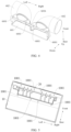
FIG. 1 is a first schematic view of a three-dimensional structure of an air outlet assembly according to an embodiment of the present application. -
FIG. 2 is a second schematic view of a three-dimensional structure of an air outlet assembly according to an embodiment of the present application. -
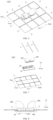
FIG. 3 is a first schematic view of a three-dimensional structure of an air duct component according to an embodiment of the present application. -
FIG. 4 is a second schematic view of a three-dimensional structure of an air duct component according to an embodiment of the present application. -
FIG. 5 is a first schematic view of a three-dimensional structure of a panel and an air deflector assembly according to an embodiment of the present application. -
FIG. 6 is a schematic view of a three-dimensional structure of a mounting structure of an air outlet assembly according to an embodiment of the present application. -
FIG. 7 is an exploded view of a mounting structure of an air outlet assembly according to an embodiment of the present application. -
FIG. 8 is a schematic view of an internal structure of a mounting structure of an air outlet assembly according to an embodiment of the present application. -
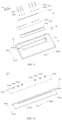
FIG. 9 is an exploded view of a panel and an air deflector assembly according to an embodiment of the present application. -
FIG. 10 is an exploded view of an air deflector according to an embodiment of the present application. -
FIG. 11 is a schematic view of a three-dimensional structure of a louver body according to an embodiment of the present application. -
FIG. 12 is a schematic view of a three-dimensional structure of a locking seat according to an embodiment of the present application. -
FIG. 13 is a schematic view of a three-dimensional structure of a link according to an embodiment of the present application. -
FIG. 14 is a schematic structural view of a first drive member according to an embodiment of the present application. -
- 1, air outlet assembly;
- 10, panel; 10a, air outlet; 1001, second connection portion;
- 20, air deflector assembly;
- 210, air deflector; 2101, base; 2101a, first recess; 2102, top cover;
- 210c, via hole;
- 220, louver; 220a, swing arm; 220b, drive post; 2201, louver body; 2201a, pivot shaft; 2202, locking seat;
- 230, link; 230a, through hole; 230b, connection post;
- 30, first drive member; 301, telescopic rod; 302, extension portion; 302a, movement groove;
- 40, second drive member;
- 60, air duct component;
- 601, air duct cover; 601a, mounting hole; 601b, avoidance groove; 6001, first connection portion;
- 602, air duct;
- 1000, mounting structure; 2, joist; 3, ceiling panel.
- Embodiments of the present application will be described in detail below with reference to examples thereof as illustrated in the accompanying drawings, throughout which same or similar elements, or elements having same or similar functions, are denoted by same or similar reference numerals. The embodiments described below with reference to the drawings are illustrative only, and are intended to explain, rather than limiting, the present application.
- Referring to
FIG. 1 to FIG. 14 , an air outlet assembly 1 of an air conditioner according to the embodiments of the present application is described below. - The air conditioner may refer to a ceiling-type air conditioner, which is mounted at a ceiling. For example, the air conditioner may be applied to a kitchen scene or other indoor scenes, which may be specifically set up as needed.
- As shown in
FIG. 1 and FIG. 2 , the air outlet component 1 of the air conditioner according to the embodiments of the present application includes apanel 10 and anair duct component 60. - The
panel 10 has anair outlet 10a. Theair duct component 60 includes anair duct cover 601 and anair duct 602. Theair duct cover 601 is disposed at thepanel 10 and covers theair outlet 10a. Theair duct cover 601 has a mounting hole 601a and anavoidance groove 601b. Theair duct 602 is disposed in the mounting hole 601a. Theavoidance groove 601b is configured to avoid ajoist 2. - When the air outlet assembly 1 is in operation, air enters the
air duct 602 from a main body of the air conditioner, then enters theair duct cover 601, and finally blows downward from theair outlet 10a. The air outlet assembly 1 is mounted at a top of a ceiling. Since the ceiling needs to use thejoist 2 to build a suspended ceiling, during mounting, thejoist 2 passing through theair duct cover 601 can be located in theavoidance groove 601b. Therefore, theair duct cover 601 avoids thejoist 2, allowing a mounting of the air outlet assembly 1 not to be limited by a direction of thejoist 2, and the mounting to be more convenient. - According to the air outlet assembly 1 of the air conditioner according to the embodiments of the present application, the
avoidance groove 601b is formed at theair duct cover 601, allowing theavoidance groove 601b to avoid thejoist 2 on the ceiling during mounting of the air outlet assembly 1. Therefore, thepanel 10 is not limited by the direction of thejoist 2 during mounting, allowing the mounting convenience to be improved, and the mounting adaptability to be strong. - In some embodiments,
avoidance groove 601b has a width gradually increasing away from thepanel 10. As shown inFIG. 3 , theavoidance groove 601b is away from thepanel 10 from down to up, that is, a width of a lower part of theavoidance groove 601b is smaller than a width of an upper part of theavoidance groove 601b. Therefore, when thejoist 2 passes through theair duct cover 601, thejoist 2 can easily enter theavoidance groove 601b from up to down. - In some embodiments, a width of a side of the
avoidance groove 601b close to thepanel 10 may be greater than or equal to the width of thejoint 2. As shown inFIG. 3 , the side of theavoidance groove 601b close to thepanel 10 may refer to the lower part of theavoidance groove 601b. When the width of the lower part of theavoidance groove 601b is greater than the width of the joint 2, the joint 2 easily enters theavoidance groove 601b. When the width of the lower part of theavoidance groove 601b is equal to the joint 2, the joint 2 does not move left and right when it is located in theavoidance groove 601b, and the reliability of the joint 2 can be improved. In some embodiments, a transition fillet or chamfer is formed between theavoidance groove 601b and theair duct cover 601. As shown inFIG. 3 , the transition fillet is formed between theavoidance groove 601b and theair duct cover 601. Therefore, an overall appearance is more rounded and more beautiful. Secondly, it can also ensure that thejoist 2 can smoothly enter theavoidance groove 601b. The transition chamfer may further be formed between theavoidance groove 601b and theair duct cover 601. Therefore, thejoist 2 can also smoothly enter theavoidance groove 601b. - In some embodiments, the
air duct cover 601 has at least oneavoidance groove 601b. One ormore avoidance grooves 601b can be adaptively provided based on the number ofjoists 2 passing through theair duct cover 601. For example, when onejoist 2 passes through, oneavoidance groove 601b is provided. When twojoists 2 pass through, twoavoidance grooves 601b are provided. This allows the mounting of thepanel 10 and theair duct cover 601 to be independent of the direction of thejoist 2. - In some embodiments, the
air duct cover 601 has oneavoidance groove 601b, and the oneavoidance groove 601b is formed at a center of theair duct cover 601. - In some embodiments, at least two mounting holes 601a are provided. The number of
air ducts 602 is equal to the number of mounting holes 601a, and theair ducts 602 are arranged to correspond to the mounting holes 601a. Theair ducts 602 blow air through thepanel 10. When the at least twoair ducts 602 are provided, the air out of theair ducts 602 first passes through theair duct cover 601 and then blows out from theair outlet 10a on thepanel 10, which can increase air volume and air speed of the air conditioner and improve the user experience by realizing theair outlet 10a. - In some embodiments, as shown in
FIG. 3 andFIG. 4 , two mounting holes 601a and twoair ducts 602 are provided, and theavoidance groove 601b is formed between the two mounting holes 601a. - In some embodiments, as shown in
FIG. 1 andFIG. 5 , the air outlet assembly 1 further includes anair deflector assembly 20. Theair deflector assembly 20 includes anair deflector 210 andlouvers 220. Theair deflector 210 is disposed at theair outlet 10a in an openable or closable manner. Thelouvers 220 are arranged at an end of theair deflector 210 close to theair duct cover 601. Theair deflector assembly 20 can guide the air to change an outlet direction of the air to realize a fixed point delivery of the air. In an exemplary embodiment of the present application, theair deflector 210 may be opened at a certain angle with theair outlet 10a, to adjust an air direction in an up-down direction. By adjusting a position of thelouvers 220, the air direction in a left-right direction can be adjusted, thereby bringing a better air outlet effect. - In some embodiments, as shown in
FIG. 9 and FIG. 10 , the air outlet assembly 1 further includes afirst drive member 30 and asecond drive member 40. A cavity (not shown) is formed in theair deflector 210, and the mountinghole 210a in communication with the cavity is formed at theair deflector 210. Thelouvers 220 partially pass through the mountinghole 210a and are pivotally connected to theair deflector 210. Alink 230 is disposed in the cavity and is linked with thelouvers 220 to drive thelouvers 220 to swing. Thefirst drive member 30 is linked with thelink 230 to drive thelink 230 to move. Thesecond drive member 40 is connected to theair deflector 210 to drive theair deflector 210 to open theair outlet 10a. When the air is discharged, thesecond drive member 40 can drive theair deflector 210 to move to open theair outlet 10a to realize the air discharge. An up- and-down air deflection is realized by theair deflector 210. Thefirst drive member 30 can drive thelink 230 to move to allow thelink 230 to drive thelouvers 220 to rotate on theair deflector 210, thereby adjusting a direction of thelouvers 220 to realize a left-and-right air deflection. - It should be noted that since the
link 230 is mounted in the cavity inside theair deflector 210, thelink 230 can be hidden. Therefore, the number of members on theair deflector 210 is relatively small, and the appearance is cleaner, allowing thepanel 10 to be easier to clean. - In some embodiments, as shown in
FIG. 9 and FIG. 10 , theair deflector 210 includes abase 2101 and atop cover 2102. Thebase 2101 has afirst recess 2101a. Thetop cover 2102 has a second recess (not shown) formed at an end of thetop cover 2102 close to thebase 2101. Thetop cover 2102 is disposed at thebase 2101, and the mountinghole 210a is formed at thetop cover 2102. The second recess and thefirst recess 2101a jointly define the cavity. That is, theair deflector 210 is composed of two parts, thebase 2101 and thetop cover 2102. Thelink 230 can be easily attached or detached by opening thetop cover 2102 from thebase 2101. - In some embodiments, as shown in
FIG. 11, FIG. 12, and FIG. 13 , thelouvers 220 are provided with aswing arm 220a. An end of theswing arm 220a away from a rotation axis of thelouvers 220 is provided with adrive post 220b. Thelink 230 has a throughhole 230a, and thedrive post 220b is disposed in the throughhole 230a. Thelink 230 may be disposed at a side of the rotation axis of thelouvers 220. When thefirst drive member 30 drives thelink 230 to move, thelink 230 can drive theswing arm 220a to swing by the throughhole 230a and thedrive post 220b, thereby driving thelouvers 220 to rotate around the rotation axis and adjusting an air deflection direction of thelouvers 220. - In some embodiments, as shown in
FIG. 11 and FIG. 12 , thelouver 220 includes alouver body 2201 and a lockingseat 2202. Thelouver body 2201 is provided with apivot shaft 2201a, and thepivot shaft 2201a is disposed in the mountinghole 210a. The lockingseat 2202 is disposed in the cavity. A width of the lockingseat 2202 is greater than a width of the mountinghole 210a. The lockingseat 2202 and thepivot shaft 2201a are detachably connected to each other. Theswing arm 220a is disposed at the lockingseat 2202. Thelouver 2201 is firstly mounted in the mountinghole 210a by thepivot shaft 2201a, and then a bottom of thepivot shaft 2201a is locked and limited by the lockingseat 2202. Since the width of the lockingseat 2202 is greater than the width of the mountinghole 210a, thelouver 2201 cannot be separated from thetop cover 2102 upward, thelouver 220 can be better mounted at theair deflector 210. - In some embodiments, as shown in
FIG. 10 , theair deflector 210 has a viahole 210c at an end of theair deflector 210 away from thesecond drive member 40. The viahole 210c is in communication with the cavity. Thefirst drive member 30 has atelescopic rod 301 disposed in the viahole 210c and connected to thelink 230. Thefirst drive member 30 may be a telescopic member that enables a telescopic movement of an end of thetelescopic rod 301. Thus, thetelescopic rod 301 can enter the cavity and be connected to thelink 230 by providing the viahole 210c, thereby controlling a movement of thelink 230. For example, referring toFIG. 10 , thetelescopic rod 301 extends and retracts in the left-right direction and drives thelink 230 to move in the left-right direction together, thereby driving theswing arm 220a to swing and rotate thelouvers 220. - In some embodiments, as shown in
FIG. 14 , anextension portion 302 is disposed at thetelescopic rod 301, and theextension portion 302 has amovement groove 302a. An extension direction of themovement groove 302a is perpendicular to a moving direction of thelink 230. Thelink 230 is provided with aconnection post 230b, and theconnection post 230b is slidably disposed in themovement groove 302a. Referring toFIG. 10 , that is, themovement groove 302a extends in a front-rear direction, and theconnection post 230b can slide along themovement groove 302a. When thetelescopic rod 301 extends and retracts in the left-right direction, theextension portion 302 can drag theconnection post 230b to move by themovement groove 302a, thereby driving thelink 230 to move in the left-right direction. By providing themovement groove 302a and theconnection post 230b, on the one hand, a mounting of thetelescopic rod 301 and thelink 230 is relatively simple, and on the other hand, requirements on positional degrees of thetelescopic rod 301 and thelink 230 are relatively low. Therefore, assembly efficiency can be improved. - In some embodiments, the
first drive member 30 may be any one of an air cylinder, an electric push rod, and a hydraulic rod. - In some embodiments, the
second drive member 40 is a rotational drive member, and the rotational drive member may refer to any one of a motor, a rotational cylinder, and a rotational oil cylinder. Theair deflector 210 has an assembly hole 210d, and an output shaft of the rotational drive member is disposed in the assembly hole 210d. - In some embodiments, the
air duct 602 is pivotally disposed in the mounting hole 601a. Theair duct 602 needs to be connected to the main body of the air conditioner. Therefore, theair duct 602 can rotate on the mounting hole 601a, which can adapt to different mounting positions and improve mounting convenience. - In some embodiments, as shown in
FIG. 3 ,FIG. 4, and FIG. 5 , theair duct cover 601 is provided with afirst connection portion 6001 at a circumferential edge of theair duct cover 601. Asecond connection portion 1001 is disposed at a part of thepanel 10 corresponding to thefirst connection portion 6001. Thesecond connection portion 1001 is detachably disposed at thefirst connection portion 6001. A connection between thesecond connection portion 1001 and thefirst connection portion 6001 can realize disassembly or mounting of theair duct cover 601 and thepanel 10, which is convenient for later maintenance or replacement. - In some embodiments, as shown in
FIG. 3 ,FIG. 4, and FIG. 5 , a plurality offirst connection portions 6001 are arranged at intervals along edges of theair duct cover 601 in a length direction of theair duct cover 601, and a plurality ofsecond connection portions 1001 arranged at intervals along edges of theair outlet 10a in a length direction of theair outlet 10a. The edges in the length direction of theair duct cover 601 may refer to front and rear edges, and the edges in the length direction of theair outlet 10a may also refer to front and rear edges. Therefore, connection reliability can be improved by the plurality offirst connection portions 6001 and the plurality ofsecond connection portions 1001. - In an exemplary embodiment of the present application, as shown in
FIG. 3 ,FIG. 4, and FIG. 5 , fourfirst connection portions 6001 can be provided at edges in the length direction of theair duct cover 601, and foursecond connection portions 1001 can be provided at edges in the length direction of theair outlet 10a. In other embodiments of the present application, the number of thefirst connection portion 6001 and thesecond connection portion 1001 may also be other numbers, which may be specifically provided based on circumstances, and are not described here. - In some embodiments, a plurality of
first connection portions 6001 can be provided at intervals along edges in a width direction of theair duct cover 601, and a plurality ofsecond connection portions 1001 can be provided at intervals along edges in a width direction of theair outlet 10a. The edges in the width direction of theair duct cover 601 may refer to left and right edges, and the edges in the width direction of theair outlet 10a may also refer to left and right edges, allowing the connection reliability to be improved. - In some embodiments, the
first connection portions 6001 can be disposed at the edge in the width direction and the edge in the length direction of theair duct cover 601, and thesecond connection portions 1001 can further be disposed at the edge in the width direction and the edge in the length direction of theair outlet 10a, which can bring higher connection reliability. - In some embodiments, as shown in
FIG. 3 andFIG. 5 , thefirst connection portion 6001 may be a bolt hole, and thesecond connection portion 1001 may be a bolt seat. In this way, a bolt passes through the bolt hole and is screwed into the bolt seat to fix theair duct cover 601 to thepanel 10. - In some embodiments, the
first connection portion 6001 may further be a snap, and thesecond connection portion 1001 may be a groove, or thefirst connection portion 6001 may be a groove, and thesecond connection portion 1001 may be a snap. The snap connection can ensure the reliability of the connection and facilitate the disassembly. - A specific embodiment of the air outlet assembly 1 of the air conditioner of the present application will be described below with reference to the accompanying drawings.
- The air outlet assembly 1 includes the
panel 10 and anair duct component 60. - The
panel 10 has theair outlet 10a. Theair duct component 60 includes theair duct cover 601 and theair duct 602. Theair duct cover 601 is disposed at thepanel 10 and covers theair outlet 10a. Theair duct cover 601 has the mounting hole 601a and theavoidance groove 601b. Theair duct 602 is disposed in the mounting hole 601a. Theavoidance groove 601b is configured to avoid thejoist 2. - The
avoidance groove 601b has the width gradually increasing away from thepanel 10. - The transition fillet is formed between the
avoidance groove 601b and theair duct cover 601. - One
avoidance groove 601b is formed at the center of theair duct cover 601. - Two mounting holes 601a and two
air ducts 602 are provided, and theavoidance groove 601b is formed between the two mounting holes 601a. - The air outlet assembly 1 further includes the
air deflector assembly 20 including theair deflector 210 and thelouvers 220. Theair deflector 210 is disposed at theair outlet 10a in an openable or closable manner. Thelouvers 220 are arranged at the end of theair deflector 210 close to theair duct cover 601. - The
air duct 602 is pivotally disposed in the mounting hole 601a. - Four
first connection portions 6001 are arranged at the edge of theair duct cover 601 in the length direction of theair duct cover 601. Thesecond connection portion 1001 is disposed at a part of thepanel 10 corresponding to the fourfirst connection portions 6001. Thesecond connection portion 1001 is detachably disposed at thefirst connection portions 6001. - The
first connection portion 6001 is the bolt hole and thesecond connection portion 1001 is the bolt seat. - As shown in
FIG. 6, FIG. 7, and FIG. 8 , the mountingstructure 1000 of the air outlet assembly 1 according to the embodiment of the present application includes a plurality ofjoists 2 and the air outlet assembly 1. - The plurality of
joists 2 is provided. Some of the plurality ofjoists 2 are arranged at intervals in a first direction, and the rest of the plurality ofjoists 2 are arranged at intervals in a second direction perpendicular to the first direction. Thepanel 10 of the air outlet assembly 1 is disposed at the plurality ofjoists 2. Theavoidance groove 601b is configured to receive one of the plurality ofjoists 2 adjacent to theavoidance groove 601b. - The first direction refers to a front-rear direction in
FIG. 6 , and the second direction refers to a left-right direction inFIG. 6 . Thejoists 2 in the first direction and the second direction are spliced to form a ceiling frame as an integral support structure. Thepanel 10 of the air outlet assembly 1 is mounted at the ceiling frame. It can be seen from the figure that one of the plurality ofjoists 2 in the first direction can be placed in theavoidance groove 601b when passing through the air outlet assembly 1, to avoid the direction of thejoist 2 affecting the mounting of the air outlet assembly 1. - For example, four
joists 2 can be provided in the first direction, and fivejoists 2 can be provided in the second direction. - According to the mounting
structure 1000 of the air outlet assembly 1 of the embodiments of the present application, the air outlet assembly 1 is adopted to enable thepanel 10 to be mounted without being limited by the direction of the joint 2, thereby improving the mounting convenience. In addition, strong mounting adaptability. - In some embodiments, the plurality of joint 2 defines a plurality of square grid holes (not shown in the figures). The mounting
structure 1000 further includesceiling panels 3. The number of theceiling panels 3 is equal to the number of the square grid holes. The plurality ofceiling panels 3 is arranged to correspond to the plurality of square grid holes. The plurality ofceiling panels 3 is mounted in the plurality of square grid holes formed, which can play an appearance and support role. In an exemplary embodiment of the present application, theceiling panel 3 may be an aluminum ceiling panel. - The air conditioner according to the embodiments of the present application includes the air outlet assembly 1 of the air conditioner described above.
- According to the air conditioner of the embodiments of the present application, the air outlet assembly 1 is adopted to enable the
panel 10 to be mounted without being limited by the direction of the joint 2, thereby improving the mounting convenience. In addition, strong mounting adaptability is also provided. - Other configurations and operations of the air conditioner according to the embodiments of the present application are known to those skilled in the art and will not be described in detail herein.
- In the description of the present application, it should be understood that the orientation or position relationship indicated by the terms such as "center", "longitudinal", "transverse", "length", "width", "thickness", "upper", "lower", "front", "rear", "left", "right", "vertical", "horizontal", "top", "bottom", "inner", "outer", "clockwise", "counterclockwise", "axial", "radial", and "circumferential" should be construed to refer to the orientation or the position as shown in the drawings, and is only for the convenience of describing the present application and simplifying the description, rather than indicating or implying that the pointed apparatus or element must have a specific orientation, or be constructed and operated in a specific orientation, and therefore cannot be understood as a limitation of the present application.
- In the description of the present application, "first feature" and "second feature" may include one or more such features.
- In the description of the present application, "plurality" means two or more. The first feature "on" or "under" the second feature may mean that the first feature is in direct contact with the second feature, or that the first feature and the second feature are in indirect contact through another feature between them.
- In the description of the present application, the first feature "above" the second feature means that the first feature is directly above and obliquely above the second feature, or simply means that the level of the first feature is higher than that of the second feature.
- In the description of this specification, description with reference to the terms "some embodiments", "exemplary embodiments", "further", or "some examples" etc., mean that specific features, structure, materials or characteristics described in conjunction with the embodiment or example are included in at least one embodiment or example of the present application. In this specification, the schematic representations of the above terms do not necessarily refer to the same embodiment or example. Moreover, the described specific features, structures, materials or characteristics may be combined in any one or more embodiments or examples in a suitable manner.
- Although embodiments of the present application have been illustrated and described, it is conceivable for those of ordinary skill in the art that various changes, modifications, replacements, and variations can be made to these embodiments without departing from the principles and spirit of the present application. The scope of the present application shall be defined by the claims as appended and their equivalents.
Claims (13)
- An air outlet assembly of an air conditioner, the air outlet assembly comprising:a panel having an air outlet; andan air duct component comprising an air duct cover and an air duct, the air duct cover disposed at the panel and covering the air outlet, the air duct cover having a mounting hole and an avoidance groove, the air duct disposed in the mounting hole, and the avoidance groove configured to avoid a joist.
- The air outlet assembly according to claim 1, wherein the avoidance groove has a width gradually increasing away from the panel.
- The air outlet assembly according to claim 2, wherein a transition fillet or a transition chamfer is formed between the avoidance groove and the air duct cover.
- The air outlet assembly according to claim 1, wherein the air duct cover has at least one avoidance groove.
- The air outlet assembly according to claim 4, wherein one avoidance groove is provided, the one avoidance groove formed at a center of the air duct cover.
- The air outlet assembly according to claim 1, wherein the air duct cover has at least two mounting holes, the number of air ducts being equal to the number of the mounting holes, and the air ducts arranged to correspond to the mounting holes.
- The air outlet assembly according to claim 6, wherein two mounting holes and two air ducts are provided, and
the avoidance groove is formed between the two mounting holes. - The air outlet assembly according to claim 1, further comprising an air deflector assembly comprising an air deflector and louvers, wherein:the air deflector is disposed at the air outlet in an openable or closable manner; andthe louvers are arranged at an end of the air deflector close to the air duct cover.
- The air outlet assembly according to claim 1, wherein the air duct is pivotally disposed in the mounting hole.
- The air outlet assembly according to claim 1, wherein:the air duct cover is provided with a first connection portion at a circumferential edge of the air duct cover; anda second connection portion is disposed at a part of the panel corresponding to the first connection portion, the second connection portion detachably disposed at the first connection portion.
- A mounting structure of an air outlet assembly, the mounting structure comprising:a plurality of joists, some of the plurality of joists arranged at intervals in a first direction, and the rest of the plurality of joists arranged at intervals in a second direction perpendicular to the first direction; andthe air outlet assembly according to any one of claims 1 to 10,wherein:the panel is disposed at the plurality of joists; andthe avoidance groove is configured to receive one of the plurality of joists adjacent to the avoidance groove.
- The mounting structure according to claim 11, wherein:the plurality of joists defines a plurality of square grid holes; andthe mounting structure further comprises ceiling panels, and the number of the ceiling panels is equal to the number of the square grid holes, the ceiling panels arranged to correspond to the square grid holes.
- An air conditioner, comprising the air outlet assembly according to any one of claims 1 to 10.
Applications Claiming Priority (3)
| Application Number | Priority Date | Filing Date | Title |
|---|---|---|---|
| CN202221763613.7U CN218096252U (en) | 2022-07-08 | 2022-07-08 | Air outlet assembly and mounting structure of air conditioner and air conditioner |
| CN202210806419.0A CN117404714A (en) | 2022-07-08 | 2022-07-08 | Air outlet assembly of air conditioner, mounting structure and air conditioner |
| PCT/CN2022/127762 WO2024007487A1 (en) | 2022-07-08 | 2022-10-26 | Air output assembly of air conditioner, and mounting structure and air conditioner |
Publications (2)
| Publication Number | Publication Date |
|---|---|
| EP4553392A1 true EP4553392A1 (en) | 2025-05-14 |
| EP4553392A4 EP4553392A4 (en) | 2025-10-15 |
Family
ID=89454069
Family Applications (1)
| Application Number | Title | Priority Date | Filing Date |
|---|---|---|---|
| EP22950046.7A Pending EP4553392A4 (en) | 2022-07-08 | 2022-10-26 | AIR CONDITIONER AIR OUTLET ASSEMBLY, AND MOUNTING STRUCTURE AND AIR CONDITIONER |
Country Status (3)
| Country | Link |
|---|---|
| US (1) | US20260002676A1 (en) |
| EP (1) | EP4553392A4 (en) |
| WO (1) | WO2024007487A1 (en) |
Family Cites Families (8)
| Publication number | Priority date | Publication date | Assignee | Title |
|---|---|---|---|---|
| JPH076681B2 (en) * | 1988-07-19 | 1995-01-30 | 株式会社竹中工務店 | System ceiling with air conditioner |
| JPH07190415A (en) * | 1993-12-28 | 1995-07-28 | Hitachi Ltd | Air conditioner |
| CN203022265U (en) * | 2012-11-28 | 2013-06-26 | 嘉兴市今顶电器科技有限公司 | Integrated ceiling device |
| CN105509143A (en) * | 2014-10-14 | 2016-04-20 | 青岛海尔空调电子有限公司 | Indoor unit of air conditioner and air conditioner |
| CN206091019U (en) * | 2016-08-28 | 2017-04-12 | 嘉兴市华阳电器有限公司 | Integrated ceiling device |
| CN109084453A (en) * | 2018-08-19 | 2018-12-25 | 浙江顶善美集成吊顶有限公司 | A kind of air inlet/outlet structure of integral type air conditioner used in kitchen |
| CN210976268U (en) * | 2019-06-26 | 2020-07-10 | 浙江友邦集成吊顶股份有限公司 | Electrical appliance for integrated ceiling and assembly structure thereof |
| CN214791826U (en) * | 2021-03-31 | 2021-11-19 | 广东美的制冷设备有限公司 | Ceiling assembly and air conditioning system |
-
2022
- 2022-10-26 US US18/992,366 patent/US20260002676A1/en active Pending
- 2022-10-26 EP EP22950046.7A patent/EP4553392A4/en active Pending
- 2022-10-26 WO PCT/CN2022/127762 patent/WO2024007487A1/en not_active Ceased
Also Published As
| Publication number | Publication date |
|---|---|
| US20260002676A1 (en) | 2026-01-01 |
| WO2024007487A1 (en) | 2024-01-11 |
| EP4553392A4 (en) | 2025-10-15 |
Similar Documents
| Publication | Publication Date | Title |
|---|---|---|
| KR100904510B1 (en) | Indoor unit of air conditioner | |
| CN204678649U (en) | Air conditioner room unit | |
| JP2018091506A (en) | Indoor unit for air conditioner and method for assembling indoor unit for air conditioner | |
| EP4553392A1 (en) | Air output assembly of air conditioner, and mounting structure and air conditioner | |
| CN218096252U (en) | Air outlet assembly and mounting structure of air conditioner and air conditioner | |
| KR100770090B1 (en) | Indoor unit of air conditioner | |
| EP4086532B1 (en) | Air conditioner indoor unit | |
| CN219014586U (en) | Air outlet structure and air conditioner | |
| CN210601947U (en) | Air guide assembly, floor type air conditioner indoor unit and air conditioner | |
| JP7030842B2 (en) | Indoor unit of air conditioner, control method of air conditioner and air conditioner | |
| KR20180104206A (en) | Air-conditioner | |
| JP3782758B2 (en) | Air conditioner wind direction adjusting device | |
| CN117404714A (en) | Air outlet assembly of air conditioner, mounting structure and air conditioner | |
| CN212511425U (en) | Air conditioner indoor unit and air conditioner | |
| JP2011058793A (en) | Air conditioner | |
| CN215062426U (en) | Air conditioner air guide structure, air conditioner indoor unit and air conditioner | |
| KR102697363B1 (en) | Floor standing air conditioner indoor unit and air conditioner | |
| JP2005331186A (en) | Air conditioner | |
| CN112146166B (en) | Air guide mechanism of air conditioner indoor unit and air conditioner indoor unit with same | |
| CN112146163B (en) | Indoor unit of air conditioner | |
| CN209326056U (en) | The housing unit of air conditioner and air conditioner with it | |
| CN217876399U (en) | Panel of air conditioner and air conditioner | |
| CN222849366U (en) | Air guide structure, panel assembly and courtyard machine | |
| CN116358146B (en) | Air outlet structure and air conditioner | |
| CN115614818B (en) | air conditioner |
Legal Events
| Date | Code | Title | Description |
|---|---|---|---|
| STAA | Information on the status of an ep patent application or granted ep patent |
Free format text: STATUS: THE INTERNATIONAL PUBLICATION HAS BEEN MADE |
|
| PUAI | Public reference made under article 153(3) epc to a published international application that has entered the european phase |
Free format text: ORIGINAL CODE: 0009012 |
|
| STAA | Information on the status of an ep patent application or granted ep patent |
Free format text: STATUS: REQUEST FOR EXAMINATION WAS MADE |
|
| 17P | Request for examination filed |
Effective date: 20250210 |
|
| AK | Designated contracting states |
Kind code of ref document: A1 Designated state(s): AL AT BE BG CH CY CZ DE DK EE ES FI FR GB GR HR HU IE IS IT LI LT LU LV MC ME MK MT NL NO PL PT RO RS SE SI SK SM TR |
|
| A4 | Supplementary search report drawn up and despatched |
Effective date: 20250911 |
|
| DAV | Request for validation of the european patent (deleted) | ||
| DAX | Request for extension of the european patent (deleted) | ||
| RIC1 | Information provided on ipc code assigned before grant |
Ipc: F24F 1/0047 20190101AFI20250905BHEP Ipc: F24F 13/02 20060101ALI20250905BHEP |