EP4553390A1 - Air conditioner indoor unit and kitchen air conditioner set - Google Patents
Air conditioner indoor unit and kitchen air conditioner set Download PDFInfo
- Publication number
- EP4553390A1 EP4553390A1 EP22950045.9A EP22950045A EP4553390A1 EP 4553390 A1 EP4553390 A1 EP 4553390A1 EP 22950045 A EP22950045 A EP 22950045A EP 4553390 A1 EP4553390 A1 EP 4553390A1
- Authority
- EP
- European Patent Office
- Prior art keywords
- air conditioner
- indoor unit
- air
- conditioner indoor
- air inlet
- Prior art date
- Legal status (The legal status is an assumption and is not a legal conclusion. Google has not performed a legal analysis and makes no representation as to the accuracy of the status listed.)
- Pending
Links
Images



Classifications
-
- F—MECHANICAL ENGINEERING; LIGHTING; HEATING; WEAPONS; BLASTING
- F24—HEATING; RANGES; VENTILATING
- F24F—AIR-CONDITIONING; AIR-HUMIDIFICATION; VENTILATION; USE OF AIR CURRENTS FOR SCREENING
- F24F13/00—Details common to, or for air-conditioning, air-humidification, ventilation or use of air currents for screening
- F24F13/22—Means for preventing condensation or evacuating condensate
-
- F—MECHANICAL ENGINEERING; LIGHTING; HEATING; WEAPONS; BLASTING
- F24—HEATING; RANGES; VENTILATING
- F24F—AIR-CONDITIONING; AIR-HUMIDIFICATION; VENTILATION; USE OF AIR CURRENTS FOR SCREENING
- F24F13/00—Details common to, or for air-conditioning, air-humidification, ventilation or use of air currents for screening
- F24F13/22—Means for preventing condensation or evacuating condensate
- F24F13/222—Means for preventing condensation or evacuating condensate for evacuating condensate
-
- F—MECHANICAL ENGINEERING; LIGHTING; HEATING; WEAPONS; BLASTING
- F04—POSITIVE - DISPLACEMENT MACHINES FOR LIQUIDS; PUMPS FOR LIQUIDS OR ELASTIC FLUIDS
- F04D—NON-POSITIVE-DISPLACEMENT PUMPS
- F04D25/00—Pumping installations or systems
- F04D25/16—Combinations of two or more pumps ; Producing two or more separate gas flows
- F04D25/166—Combinations of two or more pumps ; Producing two or more separate gas flows using fans
-
- F—MECHANICAL ENGINEERING; LIGHTING; HEATING; WEAPONS; BLASTING
- F04—POSITIVE - DISPLACEMENT MACHINES FOR LIQUIDS; PUMPS FOR LIQUIDS OR ELASTIC FLUIDS
- F04D—NON-POSITIVE-DISPLACEMENT PUMPS
- F04D29/00—Details, component parts, or accessories
- F04D29/02—Selection of particular materials
- F04D29/023—Selection of particular materials especially adapted for elastic fluid pumps
-
- F—MECHANICAL ENGINEERING; LIGHTING; HEATING; WEAPONS; BLASTING
- F04—POSITIVE - DISPLACEMENT MACHINES FOR LIQUIDS; PUMPS FOR LIQUIDS OR ELASTIC FLUIDS
- F04D—NON-POSITIVE-DISPLACEMENT PUMPS
- F04D29/00—Details, component parts, or accessories
- F04D29/70—Suction grids; Strainers; Dust separation; Cleaning
- F04D29/701—Suction grids; Strainers; Dust separation; Cleaning especially adapted for elastic fluid pumps
- F04D29/703—Suction grids; Strainers; Dust separation; Cleaning especially adapted for elastic fluid pumps specially for fans, e.g. fan guards
-
- F—MECHANICAL ENGINEERING; LIGHTING; HEATING; WEAPONS; BLASTING
- F24—HEATING; RANGES; VENTILATING
- F24F—AIR-CONDITIONING; AIR-HUMIDIFICATION; VENTILATION; USE OF AIR CURRENTS FOR SCREENING
- F24F1/00—Room units for air-conditioning, e.g. separate or self-contained units or units receiving primary air from a central station
- F24F1/0007—Indoor units, e.g. fan coil units
- F24F1/0059—Indoor units, e.g. fan coil units characterised by heat exchangers
- F24F1/0067—Indoor units, e.g. fan coil units characterised by heat exchangers by the shape of the heat exchangers or of parts thereof, e.g. of their fins
-
- F—MECHANICAL ENGINEERING; LIGHTING; HEATING; WEAPONS; BLASTING
- F24—HEATING; RANGES; VENTILATING
- F24F—AIR-CONDITIONING; AIR-HUMIDIFICATION; VENTILATION; USE OF AIR CURRENTS FOR SCREENING
- F24F13/00—Details common to, or for air-conditioning, air-humidification, ventilation or use of air currents for screening
- F24F13/20—Casings or covers
-
- F—MECHANICAL ENGINEERING; LIGHTING; HEATING; WEAPONS; BLASTING
- F24—HEATING; RANGES; VENTILATING
- F24F—AIR-CONDITIONING; AIR-HUMIDIFICATION; VENTILATION; USE OF AIR CURRENTS FOR SCREENING
- F24F1/00—Room units for air-conditioning, e.g. separate or self-contained units or units receiving primary air from a central station
- F24F1/0007—Indoor units, e.g. fan coil units
- F24F1/0043—Indoor units, e.g. fan coil units characterised by mounting arrangements
- F24F1/0047—Indoor units, e.g. fan coil units characterised by mounting arrangements mounted in the ceiling or at the ceiling
-
- F—MECHANICAL ENGINEERING; LIGHTING; HEATING; WEAPONS; BLASTING
- F24—HEATING; RANGES; VENTILATING
- F24F—AIR-CONDITIONING; AIR-HUMIDIFICATION; VENTILATION; USE OF AIR CURRENTS FOR SCREENING
- F24F13/00—Details common to, or for air-conditioning, air-humidification, ventilation or use of air currents for screening
- F24F13/20—Casings or covers
- F24F2013/205—Mounting a ventilator fan therein
-
- F—MECHANICAL ENGINEERING; LIGHTING; HEATING; WEAPONS; BLASTING
- F24—HEATING; RANGES; VENTILATING
- F24F—AIR-CONDITIONING; AIR-HUMIDIFICATION; VENTILATION; USE OF AIR CURRENTS FOR SCREENING
- F24F2221/00—Details or features not otherwise provided for
- F24F2221/14—Details or features not otherwise provided for mounted on the ceiling
Definitions
- the present disclosure relates to the technical field of kitchen air conditioners, and in particular, to an air conditioner indoor unit and a kitchen air conditioner set.
- An existing kitchen air conditioner generally adopts a central air conditioner and a conventional duct-type air conditioner for refrigeration, in which an in-line evaporator is usually employed. A manner of directly blowing is adopted in an air duct. A water pump is provided at two ends of the evaporator.
- the conventional duct-type air conditioner is large, leading to an increased size of the kitchen air conditioner.
- the kitchen air conditioner When the kitchen air conditioner is installed at a ceiling, the kitchen air conditioner may only be installed before a dropped ceiling is installed. If the kitchen air conditioner is installed after the dropped ceiling is installed, installation of the kitchen air conditioner is difficult with high installation costs. Meanwhile, it is unbeneficial to later maintenance and cleaning of the kitchen air conditioner.
- inventions of the present disclosure are to provide an air conditioner indoor unit, which can be installed by removing a ceiling panel of a ceiling corresponding to the air conditioner indoor unit after the dropped ceiling is installed. Therefore, it is beneficial to a reduction in installation difficulty of the air conditioner indoor unit and easy later maintenance and cleaning of the air conditioner indoor unit.
- An air conditioner indoor unit comprises a housing, a water receiving tray, an indoor heat exchanger, an indoor fan, and an electric control device.
- the housing has an air inlet and an air outlet.
- the water receiving tray has a water receiving region and is located above a bottom plate of the housing, and an indoor heat exchanger is provided on the water receiving tray and directly faces towards the water receiving region.
- the indoor fan comprises a fan wheel and a motor assembly.
- the motor assembly is connected to the fan wheel to drive the fan wheel to rotate.
- the electric control device is configured to control an operation state of the air conditioner indoor unit.
- the electric control device is electrically connected to the motor assembly, and the electric control device is provided above or below the motor assembly.
- the electric control device is provided above or below the motor assembly, which facilitates a reduction in an overall length and width of the air conditioner indoor unit.
- the air conditioner indoor unit can be installed by removing the ceiling panel of the ceiling corresponding to the air conditioner indoor unit after a dropped ceiling is installed, which is beneficial to reduction of the installation difficulty of the air conditioner indoor unit and easy later maintenance and cleaning of the air conditioner indoor unit.
- the water receiving tray has an avoidance region.
- the electric control device is disposed in the avoidance region and located below the motor assembly.
- the bottom plate is detachable, and the water receiving tray has a drainage hole.
- a blocking element is provided at the drainage hole, and the blocking element is configured to open or close the drainage hole.
- the air conditioner indoor unit further comprises a water pump assembly configured to guide condensed water in the water receiving region to an exterior of the housing.
- the water pump assembly is located directly above the water receiving tray.
- two fan wheels are provided and spaced apart from each other.
- the water pump assembly is located between the two fan wheels.
- the air conditioner indoor unit further comprises a detection device configured to detect a water level in the water receiving region.
- the detection device is connected to the electric control device.
- the electric control device is configured to control the air conditioner indoor unit to stop operating when the detection device detects that the water level has reached a predetermined value.
- the housing comprises an air inlet panel, an air outlet panel, and two air inlet side plates.
- the two air inlet side plates are opposite to each other. Two ends of each of the two air inlet side plates are respectively connected to the air inlet panel and the air outlet panel.
- Each of the air inlet panel and the two air inlet side plates has an air inlet, and the air outlet panel has an air outlet.
- the indoor heat exchanger is formed into a bent shape having an opening facing towards the air outlet panel, and directly faces towards the air inlet panel and the two air inlet side plates, respectively.
- the air inlet has a plurality of rectangular holes arranged at an interval.
- the air inlet further has a plurality of air inlet through holes, wherein the plurality of air inlet through holes are elongated in shape. Air inlet through holes is formed between adjacent rectangular holes.
- the fan wheel is provided with an oil-repellent and hydrophobic coating.
- the air conditioner indoor unit further comprises a volute provided with an oil-repellent and hydrophobic coating.
- the fan wheel is disposed in the volute.
- Embodiments of the present disclosure also provides a kitchen air conditioner set.
- the kitchen air conditioner set comprises the air conditioner indoor unit as described in any one of the embodiments, a return air panel, and an air outlet tube.
- the air conditioner indoor unit is adapted to be disposed above a ceiling, and the ceiling has an air outlet region.
- the return air panel is provided at the ceiling and separated from the air conditioner indoor unit.
- the air outlet tube is connected to an air outlet, and extends towards the air outlet region to guide air towards the air outlet region.
- the return air panel comprises a return air grille and a return air filtering mesh provided above the return air grille; and/or the air outlet tube is provided with an oil-repellent and hydrophobic coating.
- the kitchen air conditioner set and the above-described air conditioner indoor unit have the same advantages, and details are omitted herein.
- the disclosure herein provides many different embodiments or examples for implementing different structures of the present disclosure.
- components and arrangements of specific examples are described herein.
- the specific examples are exemplary only and are not intended to limit the present disclosure.
- the present disclosure may use repeated reference numerals and/or reference letters in different examples. Such repetition is for the purpose of simplicity and clarity and does not in itself indicate the relation between various embodiments and/or arrangements as discussed.
- the present disclosure provides examples of various specific processes and materials, but applications of other processes and/or the use of other materials are conceivable for those skilled in the art.
- An air conditioner indoor unit 100 according to the embodiments of the present disclosure is described below with reference to FIG. 1 to FIG. 8 .
- the air conditioner indoor unit 100 comprises a housing 10, a water receiving tray 20, an indoor heat exchanger 30, an indoor fan 40, and an electric control device 50 configured to control an operation state of the air conditioner indoor unit 100.
- the housing 10 has an air inlet 101 and an air outlet 102.
- the water receiving tray 20 has a water receiving region 21 and is located above a bottom plate 14 of the housing 10.
- the indoor heat exchanger 30 is provided on the water receiving tray 20 and directly faces towards the water receiving region 21.
- the indoor fan 40 comprises a fan wheel 41 and a motor assembly 42.
- the motor assembly 42 is connected to the fan wheel 41 to drive the fan wheel 41 to rotate1.
- the electric control device 50 is electrically connected to the motor assembly 421.
- the electric control device 50 is provided above or below the motor assembly 42.
- the electric control device 50 is electrically connected to the motor assembly 42 to control the motor assembly 42 to drive the fan wheel 41 to rotate or stop rotating, i.e., the electric control device 50 is used to control the air conditioner indoor unit 100 to start and stop operating.
- the electric control device 50 controls the motor assembly 42 to drive the fan wheel 41 to rotate, outside air may enter the housing 10 through the air inlet 101 to exchange heat with the indoor heat exchanger 30 and be blown to an indoor space from the air outlet 102.
- condensed water is generated during the heat exchange of the indoor heat exchanger 30 with the air.
- the indoor heat exchanger 30 is provided on the water receiving tray 20 and directly faces towards the water receiving region 21 of the water receiving tray 20.
- the condensed water generated by the indoor heat exchanger 30 can flow to the water receiving region 21 for temporary storage, which prevents water generated by the indoor heat exchanger 30 from flowing to other structures.
- the electric control device 50 is provided above or below the motor assembly 42.
- the indoor heat exchanger 30 and the water receiving tray 20 are distributed in an up-down direction, and the electric control device 50 and the motor assembly 42 are also distributed in the up-down direction, i.e., the indoor heat exchanger 30 and the electric control device 50 occupy an installation space in the up-down direction, rather than occupying an installation space of the air conditioner indoor unit 100 in a length direction of the air conditioner indoor unit 100 and an installation space of the air conditioner indoor unit 100 in a width direction of the air conditioner indoor unit 100. In this way, a reduction in an overall length and width of the air conditioner indoor unit 100 is facilitated.
- the air conditioner indoor unit 100 when the air conditioner indoor unit 100 is installed at a ceiling 200, the air conditioner indoor unit 100 may be installed by removing a ceiling panel 203 of the ceiling 200 corresponding to the air conditioner indoor unit 100 after a dropped ceiling is installed, which is beneficial to a reduction in installation difficulty of the air conditioner indoor unit 100 and easy later maintenance and cleaning of the air conditioner indoor unit 100.
- the water receiving tray 20, the indoor heat exchanger 30, the indoor fan 40, and the electric control device 50 are each installed in the housing 10.
- the water receiving tray 20 is located above the bottom plate 14, and the indoor heat exchanger 30 is disposed above the water receiving tray 20, which allows the indoor heat exchanger 30 to directly face towards the water receiving region 21 of the water receiving tray 20 in the up-down direction, enabling the water receiving region 21 to be configured as a water storage tank.
- the indoor heat exchanger 30 exchanges heat with the air
- the water generated by the indoor heat exchanger 30 can flow directly to the water storage tank under the action of gravity, to prevent the water generated by the indoor heat exchanger 30 from flowing to other structures.
- the electric control device 50 is disposed above or below the motor assembly 42.
- the electric control device 50 is disposed above or below the motor assembly 42, i.e., the electric control device 50 and the motor assembly 42 are distributed in the up-down direction.
- an electric control element would not occupy the installation space of the air conditioner indoor unit 100 in the length direction of the air conditioner indoor unit 100 and the installation space of the air conditioner indoor unit 100 in the width direction of the air conditioner indoor unit 100.
- the reduction of the overall length and width of the air conditioner indoor unit 100 is facilitated.
- an area of the ceiling panel 203 of the ceiling 200 corresponding to the air conditioner indoor unit 100 is small.
- the air conditioner indoor unit 100 of the present disclosure can be installed by removing the ceiling panel 203 of the ceiling 200 corresponding to the air conditioner indoor unit 100 after the dropped ceiling is installed.
- the electric control device 50 is disposed above or below the motor assembly 42, which can reduce the overall length and width of the air conditioner indoor unit 100. Further, when the air conditioner indoor unit 100 is installed at the ceiling 200, the air conditioner indoor unit 100 may be installed by removing the ceiling panel 203 of the ceiling 200 corresponding to the air conditioner indoor unit 100 after the dropped ceiling is installed, which facilitates the reduction of the installation difficulty of the air conditioner indoor unit 100 and the easy later maintenance and cleaning of the air conditioner indoor unit 100.
- the water receiving tray 20 has an avoidance region 22.
- the electric control device 50 is disposed in the avoidance region 22 and located below the motor assembly 42.
- the electric control device 50 may be installed in the avoidance region 22 to make full use of the installation space, making a layout more reasonable. Therefore, it is beneficial to reducing a height of the air conditioner indoor unit 100, and thus reduce a size of the air conditioner indoor unit 100.
- the avoidance region 22 is configured as an avoidance notch, and the electric control device 50 is provided at the avoidance notch in the up-down direction, to install the electric control device 50 below the motor assembly 42. Therefore, on the one hand, it is convenient to reduce a size of the water receiving tray 20, and it is beneficial to realizing a miniaturization and lightweight design of the water receiving tray 20. On the other hand, it is convenient to make full use of the installation space and reduce the height of the air conditioner indoor unit 100 through a reasonable layout of the electric control device 50 and the water receiving tray 20, and thus the size of the air conditioner indoor unit 100 is reduced.
- the bottom plate 14 is detachable, and the water receiving tray 20 has a drainage hole.
- a blocking element 23 is provided at the drainage hole, and the blocking element 23 is configured to open or close the drainage hole.
- the drainage hole is closed by the blocking element 23.
- the water receiving region 21 of the water receiving tray 20 may store the condensed water generated by the indoor heat exchanger 30.
- the bottom plate 14 may be removed, and then the blocking element 23 is controlled to open the drainage hole. At this time, water in the water receiving region 21 of the water receiving tray 20 may be discharged from the drainage hole.
- the drainage hole is formed at a lowest water level of the water receiving region 21.
- the blocking element 23 is configured as a drainage rubber plug, and the drainage rubber plug is pluggable into the drainage hole to be connected to an inner wall of the drainage hole in a sealing manner for closing the drainage hole.
- the drainage rubber plug may be removed from the drainage hole, which facilitates drainage of the water receiving tray 20 through the drainage hole. Therefore, a sealing effect of the blocking element 23 on the drainage hole is facilitated, and difficulty of blocking the drainage hole by the blocking element 23 is reduced. Moreover, it is beneficial to removal of the blocking element 23.
- the blocking element 23 may be configured as other structures capable of opening or closing the drainage hole.
- the blocking element 23 may be configured as a drainage switch, a drainage valve, or the like, and is not limited herein.
- the air conditioner indoor unit 100 further comprises a water pump assembly 60.
- the water pump assembly 60 is configured to guide condensed water in the water receiving region 21 to an exterior of the housing 10.
- the water pump assembly 60 when the air conditioner indoor unit 100 is in operation, it is possible to guide the condensed water in the water receiving region 21 to the exterior of the housing 10 by using the water pump assembly 60. In this way, a water level in the water receiving region 21 is prevented from being too high, and it is beneficial to ensuring a normal operation of the air conditioner indoor unit 100.
- the water pump assembly 60 comprises a water pump and a water pipe 61.
- the water pump has a water inlet and a drainage opening.
- the water pump in operation is capable of pumping the condensed water in the water receiving region 21 from the water inlet into the water pump and discharging the water from the drainage opening.
- the water pipe 61 is in communication with the drainage opening.
- An end of the water pipe 61 is in communication with the drainage opening of the water pump, and another end of the water pipe 61 is in communication with a drainage connector 81 of the air conditioner indoor unit 100. Therefore, the condensed water in the water receiving region 21 can be discharged out of the air conditioner indoor unit 100 along the water pipe 61 and the drainage connector 81. Therefore, the normal operation of the air conditioner indoor unit 100 is ensured.
- the water pump assembly 60 is located directly above the water receiving tray 20.
- the water pump assembly 60 is installed at a side of the water receiving tray 20 facing away from the bottom plate 14. Therefore, on the one hand, it is convenient for the water pump assembly 60 to guide the condensed water in the water receiving region 21 to the exterior of the housing 10.
- the water pump assembly 60 and the water receiving tray 20 are distributed in the up-down direction, i.e., the water pump assembly 60 occupies the installation space in the up-down direction, rather than occupying the installation space of the air conditioner indoor unit 100 in the length direction of the air conditioner indoor unit 100 and the installation space of the air conditioner indoor unit 100 in the width direction of the air conditioner indoor unit 100. As a result, the reduction of the overall length and width of the air conditioner indoor unit 100 is facilitated.
- two fan wheels 41 are provided and spaced apart from each other.
- the water pump assembly 60 is located between the two fan wheels 41.
- two fan wheels 41 are provided and spaced apart from each other in a left-right direction
- the motor assembly 42 is installed between the two fan wheels 41 and may be configured as a double-shaft motor, i.e., the motor assembly 42 has two output shafts, and the two output shafts extend in opposite directions to be in a power connection with the two fan wheels 41, respectively.
- the motor assembly 42 can control both the two fan wheels 41, allowing the two fan wheels 41 to be started or stopped synchronously.
- the water pump assembly 60 is located between the two fan wheels 41, and the water pump assembly 60 and the electric control device 50 are spaced apart from each other in a front-rear direction. In this way, installation of the motor assembly 42 is unaffected. Meanwhile, the layout is compact, which is beneficial to making full use of the installation space and to reducing the size of the air conditioner indoor unit 100.
- the air conditioner indoor unit 100 further comprises a detection device 70 configured to detect a water level in the water receiving region 21.
- the detection device 70 is connected to the electric control device 50.
- the electric control device 50 is configured to control the air conditioner indoor unit 100 to stop operating when the detection device 70 detects that the water level has reached a predetermined value.
- the detection device 70 it is possible to detect the water level in the water receiving region 21. Moreover, the electric control device 50 controls the air conditioner indoor unit 100 to stop operating when the detection device 70 detects that the water level has reached the predetermined value. Therefore, the water level in the water receiving region 21 can be prevented from being too high, providing protection in the air conditioner indoor unit 100.
- the detection device 70 may be configured as a water level switch.
- the predetermined value may be a maximum value that is reachable by the water level of the water receiving region 21 whiling ensuring the normal operation of the air conditioner indoor unit 100. Therefore, when the water level switch detects that the water level reaches the maximum value, the electric control device 50 controls the air conditioner indoor unit 100 to stop operating, to prevent the water level of the water receiving region 21 from being too high and affecting the air conditioner indoor unit 100. Therefore, it is beneficial to protecting the air conditioner indoor unit 100 and prolonging a service life of the air conditioner indoor unit 100.
- the housing 10 comprises an air inlet panel 11, an air outlet panel 12, and two air inlet side plates 13.
- the two air inlet side plates 13 are opposite to each other. Two ends of each of the two air inlet side plates 13 are respectively connected to the air inlet panel 11 and the air outlet panel 12.
- Each of the air inlet panel 11 and the two air inlet side plates 13 has an air inlet 101, and the air outlet panel 12 has an air outlet 102.
- the air inlet 101 is formed at each of the air inlet panel 11 and the two air inlet side plates 13, and the air outlet 102 is formed at the air outlet panel 12, which facilitates the outside air entering the housing 10 from the air inlet 101 and being discharged from the air outlet 102.
- an air inlet area can be increased.
- weights of the air inlet panel 11, the two air inlet side plates 13, and the air outlet panel 12 can be reduced. Therefore, it is beneficial to realization of lightweight designs of the air inlet panel 11, the two air inlet side plates 13, and the air outlet panel 12.
- the indoor heat exchanger 30 is formed into a bent shape having an opening facing towards the air outlet panel 12. Further, the indoor heat exchanger 30 directly faces towards the air inlet panel 11 and the two air inlet side plates 13.
- the indoor heat exchanger 30 into a bent shape and allowing the indoor heat exchanger 30 to directly face towards the air inlet panel 11 and the two air inlet side plates 13, heat exchange of the indoor heat exchanger 30 with air entering from the air inlet 101 of the air inlet panel 11 and the air inlet 101 of the air inlet side plates 13 is facilitated, improving heat exchange efficiency. Therefore, it is beneficial to a reduction in energy consumption of the air conditioner indoor unit 100.
- the size of the entire air conditioner indoor unit 100 is small, it is possible to increase a heat exchange area and ensure a cooling or heating effect by making the indoor heat exchanger 30 formed into the bent shape.
- an opening formed by the indoor heat exchanger 30 faces towards the air outlet panel 12.
- the indoor heat exchanger 30 is provided in a "U" shape, and its "U"-shaped opening faces towards the air outlet panel 12, to facilitate defining an installation space by the indoor heat exchanger 30 and the air outlet panel 12.
- the indoor fan 40 is installed in the installation space, and a chassis component 15 is provided above the indoor fan 40, and the fan wheel 41 directly faces towards the air outlet 102. In this way, it is convenient for the fan wheel 41 to blow air out of the air outlet 102.
- this arrangement makes the structure more compact, to make full use of the installation space, which is beneficial to a reduction in a length of the indoor heat exchanger 30 and thus in a length of the air conditioner indoor unit 100.
- the air inlet panel 11 and the two air inlet side plates 13 may be integrally formed, and the air inlet panel 11 and the two air inlet side plates 13 may be arranged in a "U" shape to form a "U"-shaped air inlet 101.
- a side of the indoor heat exchanger 30 facing away from the air outlet panel 12 directly faces towards the air inlet panel 11, and left and right sides of the indoor heat exchanger 30 directly face towards the two air inlet side plates 13, which facilitates the improvement of the heat exchange efficiency, which is beneficial to the reduction of the energy consumption of the air conditioner indoor unit 100.
- the air inlet 101 has a plurality of rectangular holes 1011 arranged at intervals.
- each of the air inlet panel 11 and the two air inlet side plates 13 has a plurality of rectangular holes 1011 arranged at intervals. Therefore, by forming the plurality of rectangular holes 1011 arranged at intervals, it is possible to enlarge the air inlet area by increasing a number of rectangular holes 1011 while ensuring a structural strength of each of the air inlet panel 11 and the two air inlet side plates 13.
- the air inlet 101 further has a plurality of elongated air inlet through holes 1012.
- Each of the plurality of air inlet through holes 1012 is formed between adjacent rectangular holes 1011 of the plurality of rectangular holes 1011.
- each of the air inlet panel 11 and the two air inlet side plates 13 has a plurality of air inlet through holes 1012.
- the air inlet through hole 1012 may be configured as a waist-type hole. Therefore, the structural strength of each of the air inlet panel 11 and the two air inlet side plates 13 can be ensured while enlarging the air inlet area.
- an oil-repellent and hydrophobic coating is provided at the air outlet 102 of the air outlet panel 12.
- the oil-repellent and hydrophobic coating it is possible to prevent oil fumes from adhering to a surface of the air outlet panel 12. Therefore, the air outlet panel 12 is more easily wiped and cleaned, which further prevents the oil fumes from adhering to an internal air duct.
- the oil-repellent and hydrophobic coating may be an easy-to-clean, long-lasting hydrophobic and oleophobic nano-anti-fouling coating.
- the coating may be cured at a room temperature or baked at a low temperature for curing, i.e., curing conditions of the coating are simple to facilitate formation of the coating. Moreover, gloss and transparency of any previous coatings are unaffected after the coating is formed.
- the coating has advantages of easy cleaning, good stain-resistant performance, good hydrophobic and oleophobic properties, acid and alkali resistance, and good flexibility.
- the oil fumes are uneasily adhered to the coating, and dirt on the surface of the coating can be easily wiped, which is beneficial to a reduction in cleaning difficulty of the air outlet panel 12.
- the oil-repellent and hydrophobic coating may also be configured as other coatings that satisfy oil-repellent and hydrophobic requirements, and is not limited herein.
- the fan wheel 41 is provided with an oil-repellent and hydrophobic coating.
- the fan wheel 41 is more easily wiped and cleaned, which further prevents the oil fumes from adhering to the internal air duct.
- the oil-repellent and hydrophobic coating may be the easy-to-clean, long-lasting hydrophobic and oleophobic nano-anti-fouling coating.
- the coating may be cured at the room temperature or baked at the low temperature for curing, i.e., the curing conditions of the coating are simple to facilitate the formation of the coating. Moreover, the gloss and transparency of any previous coatings are unaffected after the coating is formed.
- the coating has the advantages of easy cleaning, good stain-resistant performance, good hydrophobic and oleophobic properties, acid and alkali resistance, and good flexibility.
- the oil fumes are uneasily adhered to the coating, and the dirt on the surface of the coating can be easily wiped, which is beneficial to a reduction in cleaning difficulty of the fan wheel 41.
- the oil-repellent and hydrophobic coating may also be configured as other coatings that satisfy the oil-repellent and hydrophobic requirements, and is not limited herein.
- the air conditioner indoor unit 100 further comprises a volute 43.
- the fan wheel 41 is disposed in the volute 43.
- the volute 43 is provided with an oil-repellent and hydrophobic coating.
- volute 43 it is possible to protect the fan wheel 41. Moreover, by providing the oil-repellent and hydrophobic coating, it is possible to prevent the oil fumes from adhering to a surface of the volute 43. Therefore, the volute 43 is more easily wiped and cleaned, which further prevents the oil fumes from adhering to the internal air duct.
- the oil-repellent and hydrophobic coating may be the easy-to-clean, long-lasting hydrophobic and oleophobic nano-anti-fouling coating.
- the coating may be cured at the room temperature or baked at the low temperature for curing, i.e., the curing conditions of the coating are simple to facilitate the formation of the coating. Moreover, the gloss and transparency of any previous coating are unaffected after the coating is formed.
- the coating has the advantages of easy cleaning, good stain-resistant performance, good hydrophobic and oleophobic properties, acid and alkali resistance, and good flexibility.
- the oil fumes are uneasily adhered to the coating, and the dirt on the surface of the coating can be easily wiped, which is beneficial to a reduction in cleaning difficulty of the volute 43.
- the oil-repellent and hydrophobic coating may also be configured as other coatings that satisfy the oil-repellent and hydrophobic requirements, and is not limited herein.
- the air conditioner indoor unit 100 is further provided with a refrigerant input tube 82 and a refrigerant output tube 83.
- the refrigerant input tube 82, the refrigerant output tube 83, and the drainage connector 81 are all provided at one side of the air conditioner indoor unit 100. In this way, it is convenient to reduce their installation difficulty.
- Embodiments of the present disclosure also provide a kitchen air conditioner set 1000.
- the kitchen air conditioner set 1000 comprises an air conditioner indoor unit 100, a return air panel 300, and an air outlet tube 400.
- the air conditioner indoor unit 100 is the air conditioner indoor unit 100 according to any of the above embodiments.
- the air conditioner indoor unit 100 is adapted to be disposed above a ceiling 200.
- the ceiling 200 has an air outlet region 201.
- the return air panel 300 is provided at the ceiling 200 and separated from the air conditioner indoor unit 100.
- the air outlet tube 400 is connected to an air outlet 102 and extends towards the air outlet region 201 to guide air towards the air outlet region 201.
- the air conditioner indoor unit 100 is disposed above the ceiling 200, i.e., the air conditioner indoor unit 100 is embedded and hidden in the ceiling 200. In this way, the air conditioner indoor unit 100 is not directly visible outside of the ceiling 200, facilitating saving of an indoor installation space.
- indoor air can enter the air conditioner indoor unit 100 through the return air panel 300 and the air inlet 101, and is blown to the indoor space through the air outlet 102 and the air outlet region 201 after exchanging heat with the indoor heat exchanger 30.
- the return air panel 300 is separated from the air conditioner indoor unit 100, to facilitate removal of the return air panel 300, which is beneficial to easy later cleaning and replacement of the return air panel 300.
- the air outlet pipe 400 is connected between the air outlet 102 and the air outlet region 201, which allows the air outlet region 201 to be flexibly positioned based on different kitchen spaces. Therefore, versatility of the air conditioner indoor unit 100 is enhanced.
- the air conditioner indoor unit 100 is installed at a ceiling 200 of the kitchen, and a plurality of joists 204 and a plurality of plate bodies 203 are provided at the ceiling 200.
- the ceiling 200 has a return air region 202 and an air outlet region 201.
- the return air region 202 and the air outlet region 201 are each configured as a square hole, and the return air region 202 is formed at a rear side of the air conditioner indoor unit 100.
- the return air region 202 is formed at each of left and right sides of the air conditioner indoor unit 100
- the air outlet region 201 is formed at a front side of the air conditioner indoor unit 100 and located above a gas cooker.
- the air outlet region 201 may be provided with an air deflector.
- the air deflector is configured to realize vertical swing and horizontal swing. In this way, air blown out from the air outlet region 201 can close a cooking site and a food preparation site, and thus targeted air supply and enhanced user comfort is realized.
- the return air region 202 has two square holes formed therein, and the two square holes may be jointed and installed side by side.
- the formation of the two square holes may be realized by removal of two adjacent plate bodies 203, facilitating a reduction in design difficulty of the return air region 202.
- a size of each square hole may be 300mm*300mm. Since the formation of the square hole is realized by removing the ceiling panel 203, a shape size of the ceiling panel 203 is substantially the same as a shape size of the square hole.
- a dimension of the air conditioner indoor unit 100 in the length direction of the air conditioner indoor unit 100 is greater than or equal to a total length of two adjacent plate bodies 203, and a dimension of the air conditioner indoor unit 100 in the width direction of the air conditioner indoor unit 100 is smaller than a width of a single ceiling panel 203.
- the length of the air conditioner indoor unit 100 in this embodiment is a, where 629mm ⁇ a ⁇ 631mm, and the width of the air conditioner indoor unit 100 is b, where 260mm ⁇ b ⁇ 265mm.
- a is 629 mm and b is 260 mm, or a is 630 mm and b is 262 mm, or a is 631 mm and b is 263mm, i.e., when the length and width of the air conditioner indoor unit 100 satisfy the above value range, the air conditioner indoor unit 100 does not need to be installed before the dropped ceiling is installed. Instead, the air conditioner indoor unit 100 may be installed by removing the ceiling panel 203 of the ceiling 200 corresponding to the air conditioner indoor unit 100 after the dropped ceiling is installed. In this way, it is beneficial to reducing installation difficulty and installation costs of the air conditioner indoor unit 100.
- the air conditioner indoor unit 100 may be maintained, repaired, and cleaned by removing the ceiling panel 203 of the ceiling 200 corresponding to the air conditioner indoor unit 100, which is beneficial to reducing the maintenance and cleaning difficulty.
- the air outlet panel 12 is provided with an air outlet connector 1021, and the air outlet 102 is in communication with the air outlet tube 400 through the air outlet connector 1021.
- the air outlet panel 12 may be in a snap-fit connection with the air outlet connector 1021, or the air outlet panel 12 may be connected to the air outlet connector 1021 in an insertion manner.
- the air outlet panel 12 has a plurality of engagement grooves 121, and the air outlet connector 1021 has a plurality of snaps 1022.
- the plurality of engagement grooves 121 are in one-to-one correspondence with the plurality of snaps 1022, and the snaps 1022 are engaged and fixed into the engagement grooves 121, facilitating a reduction in disassembly difficulty of the air outlet connector 1021.
- the air outlet connector 1021 is in communication with the air outlet region 201 through the air outlet tube 400, and a length of the air outlet tube 400 may be designed as the installation space of the kitchen. In this way, the installation of the air conditioner indoor unit 100 is not limited by the kitchen space, i.e., the air conditioner indoor unit 100 may be flexibly installed based on the different kitchen spaces.
- the electric control device 50, the water pump assembly 60, the detection device 70, and the like may be replaced by removing the ceiling panel 203 of the ceiling 200 corresponding to the air conditioner indoor unit 100.
- the electric control device 50 of the air conditioner indoor unit 100 of the kitchen air conditioner set 1000 is provided above or below the motor assembly 42, to reduce the overall length and width of the air conditioner indoor unit 100. Further, when the air conditioner indoor unit 100 is installed at the ceiling 200, the air conditioner indoor unit 100 may be installed by removing the ceiling panel 203 of the ceiling 200 corresponding to the air conditioner indoor unit 100 after the dropped ceiling is installed. Therefore, it is beneficial to the reduction of the installation difficulty of the air conditioner indoor unit 100 and the easy later maintenance and cleaning of the air conditioner indoor unit 100.
- the return air panel 300 comprises a return air grille 301 and a return air filtering mesh 302 provided above the return air grille 301.
- An air flowing direction is denoted by a hollow arrow.
- the return air filtering mesh 302 is disposed above the return air grille 301, to provide a supporting for the return air filtering mesh 302. Moreover, the return air grille 301 and the return air filtering mesh 302 may sequentially provide a filtering for the oil fumes in the kitchen, to prevent the oil fumes from directly entering the air conditioner indoor unit 100.
- the return air grille 301 and the ceiling 200 may be in a snap-fit connection with each other, or be connected in an insertion manner, or be connected by bolts, or be magnetically engaged with each other, which is not limited herein.
- the return air grille 301 and the return air filtering mesh 302 may be in a snap-fit connection with each other, or be connected in an insertion manner, or be connected by bolts, or be magnetically engaged with each other, which is not limited herein. Therefore, it is convenient to reduce removing difficulty of the return air panel 30, and it is beneficial to the removal of the return air panel 300 in the later stage, to clean or replace the return air panel 300.
- the air outlet tube 400 is provided with an oil-repellent and hydrophobic coating. Therefore, by providing the oil-repellent and hydrophobic coating, it is possible to prevent the oil fumes from adhering to a surface of the air outlet tube 400. Therefore, the air outlet tube 400 is more easily wiped and cleaned, which further prevents the oil fumes from adhering to the internal air duct.
- the oil-repellent and hydrophobic coating is provided at each of an outer peripheral wall and an inner peripheral wall of the air outlet tube 400.
- the oil-repellent and hydrophobic coating may be the easy-to-clean, long-lasting hydrophobic and oleophobic nano-anti-fouling coating.
- the coating may be cured at the room temperature or baked at the low temperature for curing, i.e., the curing conditions of the coating are simple to facilitate the formation of the coating.
- the gloss and transparency of any previous coatings are unaffected after the coating is formed.
- the coating has the advantages of easy cleaning, good stain-resistant performance, good hydrophobic and oleophobic properties, acid and alkali resistance, and good flexibility.
- the oil fumes are uneasily adhered to the coating, and the dirt on the surface of the coating can be easily wiped, which is beneficial to a reduction in cleaning difficulty of the air outlet tube 400.
- the oil-repellent and hydrophobic coating may also be configured as other coatings that satisfy the oil-repellent and hydrophobic requirements, and is not limited herein.
- orientation or position relationship indicated by terms such as “central”, “longitudinal”, “lateral”, “length”, “width”, “thickness”, “over”, “below”, “front”, “back”, “left”, “right”, “vertical”, “horizontal”, “top”, “bottom”, “in”, “out”, “clockwise”, “anti-clockwise”, “axial”, “radial” and “circumferential” is based on the orientation or position relationship shown in the accompanying drawings, and is merely for the convenience of describing the present disclosure and simplifying the description, rather than indicating or implying that the associated device or element must have a specific orientation, or be constructed and operated in a specific orientation, and therefore cannot be understood as a limitation on the present disclosure.
- first and second are only used for descriptive purposes, and cannot be understood as indicating or implying relative importance or implicitly indicating the number of indicated technical features. Therefore, the feature associated with “first” and “second” may include one or more this feature distinctly or implicitly.
- the term “plurality” means two or more, unless defined otherwise explicitly and specifically.
- the first feature "on” or “under” the second feature may mean that the first feature is in direct contact with the second feature, or the first and second features are in indirect contact through an intermediate.
- the first feature "above” the second feature may mean that the first feature is directly above or obliquely above the second feature, or simply mean that the level of the first feature is higher than that of the second feature.
- the first feature "below” the second feature may mean that the first feature is directly below or obliquely below the second feature, or simply mean that the level of the first feature is smaller than that of the second feature.
Landscapes
- Engineering & Computer Science (AREA)
- Mechanical Engineering (AREA)
- General Engineering & Computer Science (AREA)
- Chemical & Material Sciences (AREA)
- Combustion & Propulsion (AREA)
- Physics & Mathematics (AREA)
- Thermal Sciences (AREA)
- Air Filters, Heat-Exchange Apparatuses, And Housings Of Air-Conditioning Units (AREA)
- Devices For Blowing Cold Air, Devices For Blowing Warm Air, And Means For Preventing Water Condensation In Air Conditioning Units (AREA)
Abstract
Description
- This application claims priorities to
Chinese Patent Applications No. 202210806310.7 202221776214.4 that are filed on July 08, 2022 - The present disclosure relates to the technical field of kitchen air conditioners, and in particular, to an air conditioner indoor unit and a kitchen air conditioner set.
- An existing kitchen air conditioner generally adopts a central air conditioner and a conventional duct-type air conditioner for refrigeration, in which an in-line evaporator is usually employed. A manner of directly blowing is adopted in an air duct. A water pump is provided at two ends of the evaporator. In this case, the conventional duct-type air conditioner is large, leading to an increased size of the kitchen air conditioner. When the kitchen air conditioner is installed at a ceiling, the kitchen air conditioner may only be installed before a dropped ceiling is installed. If the kitchen air conditioner is installed after the dropped ceiling is installed, installation of the kitchen air conditioner is difficult with high installation costs. Meanwhile, it is unbeneficial to later maintenance and cleaning of the kitchen air conditioner.
- The present disclosure aims to at least solve one of the technical problems existing in the prior art. Therefore, embodiments of the present disclosure are to provide an air conditioner indoor unit, which can be installed by removing a ceiling panel of a ceiling corresponding to the air conditioner indoor unit after the dropped ceiling is installed. Therefore, it is beneficial to a reduction in installation difficulty of the air conditioner indoor unit and easy later maintenance and cleaning of the air conditioner indoor unit.
- An air conditioner indoor unit according to embodiments of the present disclosure comprises a housing, a water receiving tray, an indoor heat exchanger, an indoor fan, and an electric control device. The housing has an air inlet and an air outlet. The water receiving tray has a water receiving region and is located above a bottom plate of the housing, and an indoor heat exchanger is provided on the water receiving tray and directly faces towards the water receiving region. The indoor fan comprises a fan wheel and a motor assembly. The motor assembly is connected to the fan wheel to drive the fan wheel to rotate. The electric control device is configured to control an operation state of the air conditioner indoor unit. The electric control device is electrically connected to the motor assembly, and the electric control device is provided above or below the motor assembly.
- With the air conditioner indoor unit according to the embodiments of the present disclosure, the electric control device is provided above or below the motor assembly, which facilitates a reduction in an overall length and width of the air conditioner indoor unit. Further, when installing the air conditioner indoor unit at the ceiling, the air conditioner indoor unit can be installed by removing the ceiling panel of the ceiling corresponding to the air conditioner indoor unit after a dropped ceiling is installed, which is beneficial to reduction of the installation difficulty of the air conditioner indoor unit and easy later maintenance and cleaning of the air conditioner indoor unit.
- With the air conditioner indoor unit according to some embodiments of the present disclosure, the water receiving tray has an avoidance region. The electric control device is disposed in the avoidance region and located below the motor assembly.
- In the air conditioner indoor unit according to some embodiments of the present disclosure, the bottom plate is detachable, and the water receiving tray has a drainage hole. A blocking element is provided at the drainage hole, and the blocking element is configured to open or close the drainage hole.
- The air conditioner indoor unit according to some embodiments of the present disclosure further comprises a water pump assembly configured to guide condensed water in the water receiving region to an exterior of the housing.
- In the air conditioner indoor unit according to some embodiments of the present disclosure, the water pump assembly is located directly above the water receiving tray.
- In the air conditioner indoor unit according to some embodiments of the present disclosure, two fan wheels are provided and spaced apart from each other. The water pump assembly is located between the two fan wheels.
- The air conditioner indoor unit according to some embodiments of the present disclosure further comprises a detection device configured to detect a water level in the water receiving region. The detection device is connected to the electric control device. The electric control device is configured to control the air conditioner indoor unit to stop operating when the detection device detects that the water level has reached a predetermined value.
- In the air conditioner indoor unit according to some embodiments of the present disclosure, the housing comprises an air inlet panel, an air outlet panel, and two air inlet side plates. The two air inlet side plates are opposite to each other. Two ends of each of the two air inlet side plates are respectively connected to the air inlet panel and the air outlet panel. Each of the air inlet panel and the two air inlet side plates has an air inlet, and the air outlet panel has an air outlet. The indoor heat exchanger is formed into a bent shape having an opening facing towards the air outlet panel, and directly faces towards the air inlet panel and the two air inlet side plates, respectively.
- In the air conditioner indoor unit according to some embodiments of the present disclosure, the air inlet has a plurality of rectangular holes arranged at an interval.
- In the air conditioner indoor unit according to some embodiments of the present disclosure, the air inlet further has a plurality of air inlet through holes, wherein the plurality of air inlet through holes are elongated in shape. Air inlet through holes is formed between adjacent rectangular holes.
- In the air conditioner indoor unit according to some embodiments of the present disclosure, the fan wheel is provided with an oil-repellent and hydrophobic coating.
- The air conditioner indoor unit according to some embodiments of the present disclosure further comprises a volute provided with an oil-repellent and hydrophobic coating. The fan wheel is disposed in the volute.
- Embodiments of the present disclosure also provides a kitchen air conditioner set.
- The kitchen air conditioner set according to the embodiments of the present disclosure comprises the air conditioner indoor unit as described in any one of the embodiments, a return air panel, and an air outlet tube. The air conditioner indoor unit is adapted to be disposed above a ceiling, and the ceiling has an air outlet region. The return air panel is provided at the ceiling and separated from the air conditioner indoor unit. The air outlet tube is connected to an air outlet, and extends towards the air outlet region to guide air towards the air outlet region.
- With the kitchen air conditioner set according to some embodiments of the present disclosure, the return air panel comprises a return air grille and a return air filtering mesh provided above the return air grille; and/or the air outlet tube is provided with an oil-repellent and hydrophobic coating.
- Compared with the prior art, the kitchen air conditioner set and the above-described air conditioner indoor unit have the same advantages, and details are omitted herein.
- Additional aspects and advantages of the present disclosure will be provided in part in the following description, or will become apparent in part from the following description, or can be learned from practicing of the present disclosure.
- The above and/or additional aspects and advantages of the present disclosure will become apparent and readily understood from the following description of the embodiments in conjunction with the accompanying drawings, in which:
-
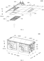
FIG. 1 is a schematic view of a kitchen air conditioner set according to some embodiments of the present disclosure. -
FIG. 2 is a partially exploded view of the kitchen air conditioner set inFIG. 1 . -
FIG. 3 is a schematic view of an air conditioner indoor unit inFIG. 2 . -
FIG. 4 is an assembly view of an indoor fan and an indoor heat exchanger of the air conditioner indoor unit inFIG. 3 . -
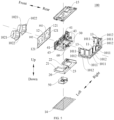
FIG. 5 is an exploded view of an air conditioner indoor unit inFIG. 2 . -
FIG. 6 is a front view of the air conditioner indoor unit inFIG. 3 . -
FIG. 7 is a cross-sectional view taken along line A-A inFIG. 6 . -
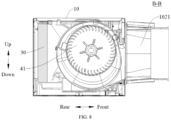
FIG. 8 is a cross-sectional view taken along line B-B inFIG. 6 . - Reference numerals:
- kitchen
air conditioner set 1000, - air conditioner
indoor unit 100, -
ceiling 200,air outlet region 201, returnair region 202,ceiling panel 203,joist 204, - return
air panel 300, returnair grille 301, returnair filtering mesh 302, -
air outlet tube 400, -
housing 10,air inlet 101,rectangular hole 1011, air inlet throughhole 1012, -
air outlet 102,air outlet connector 1021,snap 1022, -
air inlet panel 11,air outlet panel 12,engagement groove 121, - air
inlet side plate 13,bottom plate 14,chassis component 15, -
water receiving tray 20,water receiving region 21,avoidance region 22, blockingelement 23, -
indoor heat exchanger 30, -
indoor fan 40,fan wheel 41,motor assembly 42,volute 43, -
electric control device 50, -
water pump assembly 60,water pipe 61, -
detection device 70; -
drainage connector 81,refrigerant input tube 82, andrefrigerant output tube 83. - Embodiments of the present disclosure will be described in detail below with reference to examples thereof as illustrated in the accompanying drawings, throughout which same or similar elements, or elements having same or similar functions, are denoted by same or similar reference numerals. The embodiments described below with reference to the drawings are illustrative only, and are intended to explain rather than limit the present disclosure.
- The disclosure herein provides many different embodiments or examples for implementing different structures of the present disclosure. In order to simplify the disclosure, components and arrangements of specific examples are described herein. Of course, the specific examples are exemplary only and are not intended to limit the present disclosure. In addition, the present disclosure may use repeated reference numerals and/or reference letters in different examples. Such repetition is for the purpose of simplicity and clarity and does not in itself indicate the relation between various embodiments and/or arrangements as discussed. In addition, the present disclosure provides examples of various specific processes and materials, but applications of other processes and/or the use of other materials are conceivable for those skilled in the art.
- An air conditioner
indoor unit 100 according to the embodiments of the present disclosure is described below with reference toFIG. 1 to FIG. 8 . - The air conditioner
indoor unit 100 according to the embodiments of the present disclosure comprises ahousing 10, awater receiving tray 20, anindoor heat exchanger 30, anindoor fan 40, and anelectric control device 50 configured to control an operation state of the air conditionerindoor unit 100. - In an exemplary embodiment of the present disclosure, the
housing 10 has anair inlet 101 and anair outlet 102. Thewater receiving tray 20 has awater receiving region 21 and is located above abottom plate 14 of thehousing 10. Theindoor heat exchanger 30 is provided on thewater receiving tray 20 and directly faces towards thewater receiving region 21. Theindoor fan 40 comprises afan wheel 41 and amotor assembly 42. Themotor assembly 42 is connected to thefan wheel 41 to drive thefan wheel 41 to rotate1. Theelectric control device 50 is electrically connected to the motor assembly 421. Theelectric control device 50 is provided above or below themotor assembly 42. - It should be understood that the
electric control device 50 is electrically connected to themotor assembly 42 to control themotor assembly 42 to drive thefan wheel 41 to rotate or stop rotating, i.e., theelectric control device 50 is used to control the air conditionerindoor unit 100 to start and stop operating. When theelectric control device 50 controls themotor assembly 42 to drive thefan wheel 41 to rotate, outside air may enter thehousing 10 through theair inlet 101 to exchange heat with theindoor heat exchanger 30 and be blown to an indoor space from theair outlet 102. During refrigeration, condensed water is generated during the heat exchange of theindoor heat exchanger 30 with the air. Theindoor heat exchanger 30 is provided on thewater receiving tray 20 and directly faces towards thewater receiving region 21 of thewater receiving tray 20. In this way, the condensed water generated by theindoor heat exchanger 30 can flow to thewater receiving region 21 for temporary storage, which prevents water generated by theindoor heat exchanger 30 from flowing to other structures. Moreover, theelectric control device 50 is provided above or below themotor assembly 42. - In this way, the
indoor heat exchanger 30 and thewater receiving tray 20 are distributed in an up-down direction, and theelectric control device 50 and themotor assembly 42 are also distributed in the up-down direction, i.e., theindoor heat exchanger 30 and theelectric control device 50 occupy an installation space in the up-down direction, rather than occupying an installation space of the air conditionerindoor unit 100 in a length direction of the air conditionerindoor unit 100 and an installation space of the air conditionerindoor unit 100 in a width direction of the air conditionerindoor unit 100. In this way, a reduction in an overall length and width of the air conditionerindoor unit 100 is facilitated. Further, when the air conditionerindoor unit 100 is installed at aceiling 200, the air conditionerindoor unit 100 may be installed by removing aceiling panel 203 of theceiling 200 corresponding to the air conditionerindoor unit 100 after a dropped ceiling is installed, which is beneficial to a reduction in installation difficulty of the air conditionerindoor unit 100 and easy later maintenance and cleaning of the air conditionerindoor unit 100. - For example, the
water receiving tray 20, theindoor heat exchanger 30, theindoor fan 40, and theelectric control device 50 are each installed in thehousing 10. Thewater receiving tray 20 is located above thebottom plate 14, and theindoor heat exchanger 30 is disposed above thewater receiving tray 20, which allows theindoor heat exchanger 30 to directly face towards thewater receiving region 21 of thewater receiving tray 20 in the up-down direction, enabling thewater receiving region 21 to be configured as a water storage tank. In this way, when theindoor heat exchanger 30 exchanges heat with the air, the water generated by theindoor heat exchanger 30 can flow directly to the water storage tank under the action of gravity, to prevent the water generated by theindoor heat exchanger 30 from flowing to other structures. - Further, the
electric control device 50 is disposed above or below themotor assembly 42. For example, theelectric control device 50 is disposed above or below themotor assembly 42, i.e., theelectric control device 50 and themotor assembly 42 are distributed in the up-down direction. In this way, an electric control element would not occupy the installation space of the air conditionerindoor unit 100 in the length direction of the air conditionerindoor unit 100 and the installation space of the air conditionerindoor unit 100 in the width direction of the air conditionerindoor unit 100. As a result, the reduction of the overall length and width of the air conditionerindoor unit 100 is facilitated. Further, when the air conditionerindoor unit 100 is installed at theceiling 200, an area of theceiling panel 203 of theceiling 200 corresponding to the air conditionerindoor unit 100 is small. Therefore, compared with a scheme of installing the air conditionerindoor unit 100 before the dropped ceiling is installed in the prior art, the air conditionerindoor unit 100 of the present disclosure can be installed by removing theceiling panel 203 of theceiling 200 corresponding to the air conditionerindoor unit 100 after the dropped ceiling is installed. - With the air conditioner
indoor unit 100 according to the embodiments of the present disclosure, theelectric control device 50 is disposed above or below themotor assembly 42, which can reduce the overall length and width of the air conditionerindoor unit 100. Further, when the air conditionerindoor unit 100 is installed at theceiling 200, the air conditionerindoor unit 100 may be installed by removing theceiling panel 203 of theceiling 200 corresponding to the air conditionerindoor unit 100 after the dropped ceiling is installed, which facilitates the reduction of the installation difficulty of the air conditionerindoor unit 100 and the easy later maintenance and cleaning of the air conditionerindoor unit 100. - In some embodiments, as illustrated in
FIG. 5 , thewater receiving tray 20 has anavoidance region 22. Moreover, as illustrated inFIG. 4 , theelectric control device 50 is disposed in theavoidance region 22 and located below themotor assembly 42. - Therefore, it is convenient to avoid the
electric control device 50 by forming theavoidance region 22, and to prevent occurrence of interference between theelectric control device 50 and thewater receiving tray 20. Moreover, theelectric control device 50 may be installed in theavoidance region 22 to make full use of the installation space, making a layout more reasonable. Therefore, it is beneficial to reducing a height of the air conditionerindoor unit 100, and thus reduce a size of the air conditionerindoor unit 100. - For example, the
avoidance region 22 is configured as an avoidance notch, and theelectric control device 50 is provided at the avoidance notch in the up-down direction, to install theelectric control device 50 below themotor assembly 42. Therefore, on the one hand, it is convenient to reduce a size of thewater receiving tray 20, and it is beneficial to realizing a miniaturization and lightweight design of thewater receiving tray 20. On the other hand, it is convenient to make full use of the installation space and reduce the height of the air conditionerindoor unit 100 through a reasonable layout of theelectric control device 50 and thewater receiving tray 20, and thus the size of the air conditionerindoor unit 100 is reduced. - In some embodiments, the
bottom plate 14 is detachable, and thewater receiving tray 20 has a drainage hole. Moreover, as illustrated inFIG. 5 , a blockingelement 23 is provided at the drainage hole, and the blockingelement 23 is configured to open or close the drainage hole. - Therefore, when it is unnecessary to drain the
water receiving tray 20, the drainage hole is closed by the blockingelement 23. At this time, thewater receiving region 21 of thewater receiving tray 20 may store the condensed water generated by theindoor heat exchanger 30. When it is necessary to drain thewater receiving tray 20, thebottom plate 14 may be removed, and then the blockingelement 23 is controlled to open the drainage hole. At this time, water in thewater receiving region 21 of thewater receiving tray 20 may be discharged from the drainage hole. - For example, the drainage hole is formed at a lowest water level of the
water receiving region 21. In this way, when the drainage hole is opened by the blockingelement 23, the condensed water in thewater receiving region 21 can be completely drained from the drainage hole, to avoid a problem of water leakage when removing thewater receiving tray 20. The blockingelement 23 is configured as a drainage rubber plug, and the drainage rubber plug is pluggable into the drainage hole to be connected to an inner wall of the drainage hole in a sealing manner for closing the drainage hole. Moreover, the drainage rubber plug may be removed from the drainage hole, which facilitates drainage of thewater receiving tray 20 through the drainage hole. Therefore, a sealing effect of the blockingelement 23 on the drainage hole is facilitated, and difficulty of blocking the drainage hole by the blockingelement 23 is reduced. Moreover, it is beneficial to removal of the blockingelement 23. - It should be noted that the above-described drainage rubber plug is taken as an example for illustration only, and the blocking
element 23 may be configured as other structures capable of opening or closing the drainage hole. For example, the blockingelement 23 may be configured as a drainage switch, a drainage valve, or the like, and is not limited herein. - In some embodiments, as illustrated in
FIG. 5 andFIG. 7 , the air conditionerindoor unit 100 further comprises awater pump assembly 60. Thewater pump assembly 60 is configured to guide condensed water in thewater receiving region 21 to an exterior of thehousing 10. - Therefore, by providing the
water pump assembly 60, when the air conditionerindoor unit 100 is in operation, it is possible to guide the condensed water in thewater receiving region 21 to the exterior of thehousing 10 by using thewater pump assembly 60. In this way, a water level in thewater receiving region 21 is prevented from being too high, and it is beneficial to ensuring a normal operation of the air conditionerindoor unit 100. - For example, the
water pump assembly 60 comprises a water pump and awater pipe 61. The water pump has a water inlet and a drainage opening. The water pump in operation is capable of pumping the condensed water in thewater receiving region 21 from the water inlet into the water pump and discharging the water from the drainage opening. Thewater pipe 61 is in communication with the drainage opening. An end of thewater pipe 61 is in communication with the drainage opening of the water pump, and another end of thewater pipe 61 is in communication with adrainage connector 81 of the air conditionerindoor unit 100. Therefore, the condensed water in thewater receiving region 21 can be discharged out of the air conditionerindoor unit 100 along thewater pipe 61 and thedrainage connector 81. Therefore, the normal operation of the air conditionerindoor unit 100 is ensured. - Further, as illustrated in
FIG. 7 , thewater pump assembly 60 is located directly above thewater receiving tray 20. - That is, the
water pump assembly 60 is installed at a side of thewater receiving tray 20 facing away from thebottom plate 14. Therefore, on the one hand, it is convenient for thewater pump assembly 60 to guide the condensed water in thewater receiving region 21 to the exterior of thehousing 10. On the other hand, thewater pump assembly 60 and thewater receiving tray 20 are distributed in the up-down direction, i.e., thewater pump assembly 60 occupies the installation space in the up-down direction, rather than occupying the installation space of the air conditionerindoor unit 100 in the length direction of the air conditionerindoor unit 100 and the installation space of the air conditionerindoor unit 100 in the width direction of the air conditionerindoor unit 100. As a result, the reduction of the overall length and width of the air conditionerindoor unit 100 is facilitated. - As illustrated in
FIG. 4 andFIG. 7 , twofan wheels 41 are provided and spaced apart from each other. Thewater pump assembly 60 is located between the twofan wheels 41. - Therefore, it is convenient to fully utilize an installation space between the two
fan wheels 41, and a space utilization rate is improved to reduce the size of the air conditionerindoor unit 100. - For example, as illustrated in
FIG. 4 , twofan wheels 41 are provided and spaced apart from each other in a left-right direction, and themotor assembly 42 is installed between the twofan wheels 41 and may be configured as a double-shaft motor, i.e., themotor assembly 42 has two output shafts, and the two output shafts extend in opposite directions to be in a power connection with the twofan wheels 41, respectively. In this way, themotor assembly 42 can control both the twofan wheels 41, allowing the twofan wheels 41 to be started or stopped synchronously. Moreover, it is beneficial to saving the arrangement of one motor and to realizing a lightweight and miniaturization design of theindoor fan 40. - Further, the
water pump assembly 60 is located between the twofan wheels 41, and thewater pump assembly 60 and theelectric control device 50 are spaced apart from each other in a front-rear direction. In this way, installation of themotor assembly 42 is unaffected. Meanwhile, the layout is compact, which is beneficial to making full use of the installation space and to reducing the size of the air conditionerindoor unit 100. - In some embodiments, as illustrated in
FIG. 5 , the air conditionerindoor unit 100 further comprises adetection device 70 configured to detect a water level in thewater receiving region 21. - In an exemplary embodiment of the present disclosure, the
detection device 70 is connected to theelectric control device 50. Theelectric control device 50 is configured to control the air conditionerindoor unit 100 to stop operating when thedetection device 70 detects that the water level has reached a predetermined value. - Therefore, by providing the
detection device 70, it is possible to detect the water level in thewater receiving region 21. Moreover, theelectric control device 50 controls the air conditionerindoor unit 100 to stop operating when thedetection device 70 detects that the water level has reached the predetermined value. Therefore, the water level in thewater receiving region 21 can be prevented from being too high, providing protection in the air conditionerindoor unit 100. - For example, the
detection device 70 may be configured as a water level switch. Moreover, the predetermined value may be a maximum value that is reachable by the water level of thewater receiving region 21 whiling ensuring the normal operation of the air conditionerindoor unit 100. Therefore, when the water level switch detects that the water level reaches the maximum value, theelectric control device 50 controls the air conditionerindoor unit 100 to stop operating, to prevent the water level of thewater receiving region 21 from being too high and affecting the air conditionerindoor unit 100. Therefore, it is beneficial to protecting the air conditionerindoor unit 100 and prolonging a service life of the air conditionerindoor unit 100. - In some embodiments, as illustrated in
FIG. 5 , thehousing 10 comprises anair inlet panel 11, anair outlet panel 12, and two airinlet side plates 13. The two airinlet side plates 13 are opposite to each other. Two ends of each of the two airinlet side plates 13 are respectively connected to theair inlet panel 11 and theair outlet panel 12. Each of theair inlet panel 11 and the two airinlet side plates 13 has anair inlet 101, and theair outlet panel 12 has anair outlet 102. - Therefore, the
air inlet 101 is formed at each of theair inlet panel 11 and the two airinlet side plates 13, and theair outlet 102 is formed at theair outlet panel 12, which facilitates the outside air entering thehousing 10 from theair inlet 101 and being discharged from theair outlet 102. In this way, on the one hand, an air inlet area can be increased. On the other hand, weights of theair inlet panel 11, the two airinlet side plates 13, and theair outlet panel 12 can be reduced. Therefore, it is beneficial to realization of lightweight designs of theair inlet panel 11, the two airinlet side plates 13, and theair outlet panel 12. - The
indoor heat exchanger 30 is formed into a bent shape having an opening facing towards theair outlet panel 12. Further, theindoor heat exchanger 30 directly faces towards theair inlet panel 11 and the two airinlet side plates 13. - Therefore, by designing the
indoor heat exchanger 30 into a bent shape and allowing theindoor heat exchanger 30 to directly face towards theair inlet panel 11 and the two airinlet side plates 13, heat exchange of theindoor heat exchanger 30 with air entering from theair inlet 101 of theair inlet panel 11 and theair inlet 101 of the airinlet side plates 13 is facilitated, improving heat exchange efficiency. Therefore, it is beneficial to a reduction in energy consumption of the air conditionerindoor unit 100. In addition, when the size of the entire air conditionerindoor unit 100 is small, it is possible to increase a heat exchange area and ensure a cooling or heating effect by making theindoor heat exchanger 30 formed into the bent shape. - For example, an opening formed by the
indoor heat exchanger 30 faces towards theair outlet panel 12. As illustrated inFIG. 7 , theindoor heat exchanger 30 is provided in a "U" shape, and its "U"-shaped opening faces towards theair outlet panel 12, to facilitate defining an installation space by theindoor heat exchanger 30 and theair outlet panel 12. Theindoor fan 40 is installed in the installation space, and achassis component 15 is provided above theindoor fan 40, and thefan wheel 41 directly faces towards theair outlet 102. In this way, it is convenient for thefan wheel 41 to blow air out of theair outlet 102. Moreover, this arrangement makes the structure more compact, to make full use of the installation space, which is beneficial to a reduction in a length of theindoor heat exchanger 30 and thus in a length of the air conditionerindoor unit 100. - Further, as illustrated in
FIG. 5 , theair inlet panel 11 and the two airinlet side plates 13 may be integrally formed, and theair inlet panel 11 and the two airinlet side plates 13 may be arranged in a "U" shape to form a "U"-shapedair inlet 101. A side of theindoor heat exchanger 30 facing away from theair outlet panel 12 directly faces towards theair inlet panel 11, and left and right sides of theindoor heat exchanger 30 directly face towards the two airinlet side plates 13, which facilitates the improvement of the heat exchange efficiency, which is beneficial to the reduction of the energy consumption of the air conditionerindoor unit 100. - In some embodiments, as illustrated in
FIG. 5 , theair inlet 101 has a plurality ofrectangular holes 1011 arranged at intervals. - That is, each of the
air inlet panel 11 and the two airinlet side plates 13 has a plurality ofrectangular holes 1011 arranged at intervals. Therefore, by forming the plurality ofrectangular holes 1011 arranged at intervals, it is possible to enlarge the air inlet area by increasing a number ofrectangular holes 1011 while ensuring a structural strength of each of theair inlet panel 11 and the two airinlet side plates 13. - Further, as illustrated in
FIG. 5 , theair inlet 101 further has a plurality of elongated air inlet throughholes 1012. Each of the plurality of air inlet throughholes 1012 is formed between adjacentrectangular holes 1011 of the plurality ofrectangular holes 1011. - That is, each of the
air inlet panel 11 and the two airinlet side plates 13 has a plurality of air inlet throughholes 1012. For example, the air inlet throughhole 1012 may be configured as a waist-type hole. Therefore, the structural strength of each of theair inlet panel 11 and the two airinlet side plates 13 can be ensured while enlarging the air inlet area. - In some embodiments, an oil-repellent and hydrophobic coating is provided at the
air outlet 102 of theair outlet panel 12. - Therefore, by providing the oil-repellent and hydrophobic coating, it is possible to prevent oil fumes from adhering to a surface of the
air outlet panel 12. Therefore, theair outlet panel 12 is more easily wiped and cleaned, which further prevents the oil fumes from adhering to an internal air duct. - For example, the oil-repellent and hydrophobic coating may be an easy-to-clean, long-lasting hydrophobic and oleophobic nano-anti-fouling coating. The coating may be cured at a room temperature or baked at a low temperature for curing, i.e., curing conditions of the coating are simple to facilitate formation of the coating. Moreover, gloss and transparency of any previous coatings are unaffected after the coating is formed. The coating has advantages of easy cleaning, good stain-resistant performance, good hydrophobic and oleophobic properties, acid and alkali resistance, and good flexibility.
- Therefore, the oil fumes are uneasily adhered to the coating, and dirt on the surface of the coating can be easily wiped, which is beneficial to a reduction in cleaning difficulty of the
air outlet panel 12. - In other embodiments of the present disclosure, the oil-repellent and hydrophobic coating may also be configured as other coatings that satisfy oil-repellent and hydrophobic requirements, and is not limited herein.
- In some embodiments, the
fan wheel 41 is provided with an oil-repellent and hydrophobic coating. - Therefore, by providing the oil-repellent and hydrophobic coating, it is possible to prevent the oil fumes from adhering to a surface of the
fan wheel 41. Therefore, thefan wheel 41 is more easily wiped and cleaned, which further prevents the oil fumes from adhering to the internal air duct. - For example, the oil-repellent and hydrophobic coating may be the easy-to-clean, long-lasting hydrophobic and oleophobic nano-anti-fouling coating. The coating may be cured at the room temperature or baked at the low temperature for curing, i.e., the curing conditions of the coating are simple to facilitate the formation of the coating. Moreover, the gloss and transparency of any previous coatings are unaffected after the coating is formed. The coating has the advantages of easy cleaning, good stain-resistant performance, good hydrophobic and oleophobic properties, acid and alkali resistance, and good flexibility.
- Therefore, the oil fumes are uneasily adhered to the coating, and the dirt on the surface of the coating can be easily wiped, which is beneficial to a reduction in cleaning difficulty of the
fan wheel 41. - In other embodiments of the present disclosure, the oil-repellent and hydrophobic coating may also be configured as other coatings that satisfy the oil-repellent and hydrophobic requirements, and is not limited herein.
- In some embodiments, the air conditioner
indoor unit 100 further comprises avolute 43. Thefan wheel 41 is disposed in thevolute 43. Thevolute 43 is provided with an oil-repellent and hydrophobic coating. - Therefore, by providing the
volute 43, it is possible to protect thefan wheel 41. Moreover, by providing the oil-repellent and hydrophobic coating, it is possible to prevent the oil fumes from adhering to a surface of thevolute 43. Therefore, thevolute 43 is more easily wiped and cleaned, which further prevents the oil fumes from adhering to the internal air duct. - For example, the oil-repellent and hydrophobic coating may be the easy-to-clean, long-lasting hydrophobic and oleophobic nano-anti-fouling coating. The coating may be cured at the room temperature or baked at the low temperature for curing, i.e., the curing conditions of the coating are simple to facilitate the formation of the coating. Moreover, the gloss and transparency of any previous coating are unaffected after the coating is formed. The coating has the advantages of easy cleaning, good stain-resistant performance, good hydrophobic and oleophobic properties, acid and alkali resistance, and good flexibility.
- Therefore, the oil fumes are uneasily adhered to the coating, and the dirt on the surface of the coating can be easily wiped, which is beneficial to a reduction in cleaning difficulty of the
volute 43. - In other embodiments of the present disclosure, the oil-repellent and hydrophobic coating may also be configured as other coatings that satisfy the oil-repellent and hydrophobic requirements, and is not limited herein.
- In some embodiments, as illustrated in
FIG. 3 andFIG. 4 , the air conditionerindoor unit 100 is further provided with arefrigerant input tube 82 and arefrigerant output tube 83. - The
refrigerant input tube 82, therefrigerant output tube 83, and thedrainage connector 81 are all provided at one side of the air conditionerindoor unit 100. In this way, it is convenient to reduce their installation difficulty. - Embodiments of the present disclosure also provide a kitchen
air conditioner set 1000. - The kitchen air conditioner set 1000 according to the embodiments of the present disclosure comprises an air conditioner
indoor unit 100, areturn air panel 300, and anair outlet tube 400. - In an exemplary embodiment of the present disclosure, as illustrated in
FIG. 1 andFIG. 2 , the air conditionerindoor unit 100 is the air conditionerindoor unit 100 according to any of the above embodiments. The air conditionerindoor unit 100 is adapted to be disposed above aceiling 200. Theceiling 200 has anair outlet region 201. Thereturn air panel 300 is provided at theceiling 200 and separated from the air conditionerindoor unit 100. Theair outlet tube 400 is connected to anair outlet 102 and extends towards theair outlet region 201 to guide air towards theair outlet region 201. - It should be understood that the air conditioner
indoor unit 100 is disposed above theceiling 200, i.e., the air conditionerindoor unit 100 is embedded and hidden in theceiling 200. In this way, the air conditionerindoor unit 100 is not directly visible outside of theceiling 200, facilitating saving of an indoor installation space. Moreover, indoor air can enter the air conditionerindoor unit 100 through thereturn air panel 300 and theair inlet 101, and is blown to the indoor space through theair outlet 102 and theair outlet region 201 after exchanging heat with theindoor heat exchanger 30. Thereturn air panel 300 is separated from the air conditionerindoor unit 100, to facilitate removal of thereturn air panel 300, which is beneficial to easy later cleaning and replacement of thereturn air panel 300. In addition, theair outlet pipe 400 is connected between theair outlet 102 and theair outlet region 201, which allows theair outlet region 201 to be flexibly positioned based on different kitchen spaces. Therefore, versatility of the air conditionerindoor unit 100 is enhanced. - For example, as illustrated in
FIG. 1 andFIG. 2 , the air conditionerindoor unit 100 is installed at aceiling 200 of the kitchen, and a plurality ofjoists 204 and a plurality ofplate bodies 203 are provided at theceiling 200. Theceiling 200 has areturn air region 202 and anair outlet region 201. Thereturn air region 202 and theair outlet region 201 are each configured as a square hole, and thereturn air region 202 is formed at a rear side of the air conditionerindoor unit 100. In another embodiment, thereturn air region 202 is formed at each of left and right sides of the air conditionerindoor unit 100, and theair outlet region 201 is formed at a front side of the air conditionerindoor unit 100 and located above a gas cooker. Theair outlet region 201 may be provided with an air deflector. The air deflector is configured to realize vertical swing and horizontal swing. In this way, air blown out from theair outlet region 201 can close a cooking site and a food preparation site, and thus targeted air supply and enhanced user comfort is realized. - It should be noted that the
return air region 202 has two square holes formed therein, and the two square holes may be jointed and installed side by side. In addition, the formation of the two square holes may be realized by removal of twoadjacent plate bodies 203, facilitating a reduction in design difficulty of thereturn air region 202. A size of each square hole may be 300mm*300mm. Since the formation of the square hole is realized by removing theceiling panel 203, a shape size of theceiling panel 203 is substantially the same as a shape size of the square hole. - Further, as illustrated in
FIG. 1 , when the air conditionerindoor unit 100 in this embodiment is installed at theceiling 200, a dimension of the air conditionerindoor unit 100 in the length direction of the air conditionerindoor unit 100 is greater than or equal to a total length of twoadjacent plate bodies 203, and a dimension of the air conditionerindoor unit 100 in the width direction of the air conditionerindoor unit 100 is smaller than a width of asingle ceiling panel 203. - For example, as illustrated in
FIG. 3 , the length of the air conditionerindoor unit 100 in this embodiment is a, where 629mm≤a≤631mm, and the width of the air conditionerindoor unit 100 is b, where 260mm≤b≤265mm. - For example, a is 629 mm and b is 260 mm, or a is 630 mm and b is 262 mm, or a is 631 mm and b is 263mm, i.e., when the length and width of the air conditioner
indoor unit 100 satisfy the above value range, the air conditionerindoor unit 100 does not need to be installed before the dropped ceiling is installed. Instead, the air conditionerindoor unit 100 may be installed by removing theceiling panel 203 of theceiling 200 corresponding to the air conditionerindoor unit 100 after the dropped ceiling is installed. In this way, it is beneficial to reducing installation difficulty and installation costs of the air conditionerindoor unit 100. Meanwhile, after the air conditionerindoor unit 100 is used for a long time, the air conditionerindoor unit 100 may be maintained, repaired, and cleaned by removing theceiling panel 203 of theceiling 200 corresponding to the air conditionerindoor unit 100, which is beneficial to reducing the maintenance and cleaning difficulty. - Further, as illustrated in
FIG. 3 ,FIG. 6 , andFIG. 8 , theair outlet panel 12 is provided with anair outlet connector 1021, and theair outlet 102 is in communication with theair outlet tube 400 through theair outlet connector 1021. Theair outlet panel 12 may be in a snap-fit connection with theair outlet connector 1021, or theair outlet panel 12 may be connected to theair outlet connector 1021 in an insertion manner. For example, theair outlet panel 12 has a plurality ofengagement grooves 121, and theair outlet connector 1021 has a plurality ofsnaps 1022. The plurality ofengagement grooves 121 are in one-to-one correspondence with the plurality ofsnaps 1022, and thesnaps 1022 are engaged and fixed into theengagement grooves 121, facilitating a reduction in disassembly difficulty of theair outlet connector 1021. - The
air outlet connector 1021 is in communication with theair outlet region 201 through theair outlet tube 400, and a length of theair outlet tube 400 may be designed as the installation space of the kitchen. In this way, the installation of the air conditionerindoor unit 100 is not limited by the kitchen space, i.e., the air conditionerindoor unit 100 may be flexibly installed based on the different kitchen spaces. - Meanwhile, without removing the entire air conditioner
indoor unit 100, theelectric control device 50, thewater pump assembly 60, thedetection device 70, and the like may be replaced by removing theceiling panel 203 of theceiling 200 corresponding to the air conditionerindoor unit 100. - With the kitchen air conditioner set 1000 according to the embodiments of the present disclosure, the
electric control device 50 of the air conditionerindoor unit 100 of the kitchenair conditioner set 1000 is provided above or below themotor assembly 42, to reduce the overall length and width of the air conditionerindoor unit 100. Further, when the air conditionerindoor unit 100 is installed at theceiling 200, the air conditionerindoor unit 100 may be installed by removing theceiling panel 203 of theceiling 200 corresponding to the air conditionerindoor unit 100 after the dropped ceiling is installed. Therefore, it is beneficial to the reduction of the installation difficulty of the air conditionerindoor unit 100 and the easy later maintenance and cleaning of the air conditionerindoor unit 100. - In some embodiments, as illustrated in
FIG. 2 , thereturn air panel 300 comprises areturn air grille 301 and a returnair filtering mesh 302 provided above thereturn air grille 301. An air flowing direction is denoted by a hollow arrow. - Therefore, by providing the
return air grille 301, the returnair filtering mesh 302 is disposed above thereturn air grille 301, to provide a supporting for the returnair filtering mesh 302. Moreover, thereturn air grille 301 and the returnair filtering mesh 302 may sequentially provide a filtering for the oil fumes in the kitchen, to prevent the oil fumes from directly entering the air conditionerindoor unit 100. - The
return air grille 301 and theceiling 200 may be in a snap-fit connection with each other, or be connected in an insertion manner, or be connected by bolts, or be magnetically engaged with each other, which is not limited herein. Thereturn air grille 301 and the returnair filtering mesh 302 may be in a snap-fit connection with each other, or be connected in an insertion manner, or be connected by bolts, or be magnetically engaged with each other, which is not limited herein. Therefore, it is convenient to reduce removing difficulty of thereturn air panel 30, and it is beneficial to the removal of thereturn air panel 300 in the later stage, to clean or replace thereturn air panel 300. - And/or, the
air outlet tube 400 is provided with an oil-repellent and hydrophobic coating. Therefore, by providing the oil-repellent and hydrophobic coating, it is possible to prevent the oil fumes from adhering to a surface of theair outlet tube 400. Therefore, theair outlet tube 400 is more easily wiped and cleaned, which further prevents the oil fumes from adhering to the internal air duct. - For example, the oil-repellent and hydrophobic coating is provided at each of an outer peripheral wall and an inner peripheral wall of the
air outlet tube 400. Moreover, the oil-repellent and hydrophobic coating may be the easy-to-clean, long-lasting hydrophobic and oleophobic nano-anti-fouling coating. The coating may be cured at the room temperature or baked at the low temperature for curing, i.e., the curing conditions of the coating are simple to facilitate the formation of the coating. Moreover, the gloss and transparency of any previous coatings are unaffected after the coating is formed. The coating has the advantages of easy cleaning, good stain-resistant performance, good hydrophobic and oleophobic properties, acid and alkali resistance, and good flexibility. - Therefore, the oil fumes are uneasily adhered to the coating, and the dirt on the surface of the coating can be easily wiped, which is beneficial to a reduction in cleaning difficulty of the
air outlet tube 400. - In other embodiments of the present disclosure, the oil-repellent and hydrophobic coating may also be configured as other coatings that satisfy the oil-repellent and hydrophobic requirements, and is not limited herein.
- In the description of the present disclosure, it needs to be understood that, orientation or position relationship indicated by terms such as "central", "longitudinal", "lateral", "length", "width", "thickness", "over", "below", "front", "back", "left", "right", "vertical", "horizontal", "top", "bottom", "in", "out", "clockwise", "anti-clockwise", "axial", "radial" and "circumferential" is based on the orientation or position relationship shown in the accompanying drawings, and is merely for the convenience of describing the present disclosure and simplifying the description, rather than indicating or implying that the associated device or element must have a specific orientation, or be constructed and operated in a specific orientation, and therefore cannot be understood as a limitation on the present disclosure.
- In addition, the terms "first" and "second" are only used for descriptive purposes, and cannot be understood as indicating or implying relative importance or implicitly indicating the number of indicated technical features. Therefore, the feature associated with "first" and "second" may include one or more this feature distinctly or implicitly. In the description of the present disclosure, the term "plurality" means two or more, unless defined otherwise explicitly and specifically.
- In the present disclosure, unless otherwise clearly specified and limited, terms such as "install," "connect," "connect to," "fix," and the like should be understood in a broad sense. For example, it may be a fixed connection or a detachable connection or connection as one piece; mechanical connection or electrical connection or communication; direct connection or indirect connection through an intermediate; internal communication of two components or the interaction relationship between two components. For those of ordinary skill in the art, the specific meanings of the above terms in the present disclosure can be interpreted depending on specific situations.
- In the present disclosure, unless expressly stipulated and defined otherwise, the first feature "on" or "under" the second feature may mean that the first feature is in direct contact with the second feature, or the first and second features are in indirect contact through an intermediate. Moreover, the first feature "above" the second feature may mean that the first feature is directly above or obliquely above the second feature, or simply mean that the level of the first feature is higher than that of the second feature. The first feature "below" the second feature may mean that the first feature is directly below or obliquely below the second feature, or simply mean that the level of the first feature is smaller than that of the second feature.
- In descriptions of the present disclosure, descriptions with reference to the terms "an embodiment", "some embodiments", "examples", "specific examples", or "some examples" etc., mean that specific features, structure, materials, or characteristics described in conjunction with the embodiment or example are comprised in at least one embodiment or example of the present disclosure. In this specification, the schematic representations of the above terms do not necessarily refer to the same embodiment or example. Moreover, the described specific features, structures, materials or characteristics may be combined in any one or more embodiments or examples in a suitable manner. In addition, those skilled in the art may combine the different embodiments or examples and the features of the different embodiments or examples described in this specification without contradicting each other.
- Although the embodiments of the present disclosure have been shown and described above, it can be understood by those of ordinary skill in the art that various changes, modifications, replacements, and variations can be made to these embodiments without departing from the principles and ideas of the present disclosure. The scope of the present disclosure is defined by the claims as appended and their equivalents.
Claims (14)
- An air conditioner indoor unit, comprising:a housing having an air inlet and an air outlet;a water receiving tray having a water receiving region and located above a bottom plate of the housing;an indoor heat exchanger provided on the water receiving tray and directly facing towards the water receiving region;an indoor fan comprising a fan wheel and a motor assembly, the motor assembly being connected to the fan wheel to drive the fan wheel to rotate; andan electric control device configured to control an operation state of the air conditioner indoor unit, the electric control device being electrically connected to the motor assembly, and the electric control device being provided above or below the motor assembly.
- The air conditioner indoor unit according to claim 1, wherein the water receiving tray has an avoidance region, the electric control device being disposed in the avoidance region and located below the motor assembly.
- The air conditioner indoor unit according to claim 1 or 2, wherein:the bottom plate is detachable; andthe water receiving tray has a drainage hole, a blocking element being provided at the drainage hole, and the blocking element being configured to open or close the drainage hole.
- The air conditioner indoor unit according to any one of claims 1 to 3, further comprising a water pump assembly configured to guide condensed water in the water receiving region to an exterior of the housing.
- The air conditioner indoor unit according to claim 4, wherein the water pump assembly is located directly above the water receiving tray.
- The air conditioner indoor unit according to claim 4 or 5, wherein two fan wheels are provided and spaced apart from each other, the water pump assembly being located between the two fan wheels.
- The air conditioner indoor unit according to any one of claims 4 to 6, further comprising a detection device configured to detect a water level in the water receiving region, the detection device being connected to the electric control device,
wherein the electric control device is configured to control the air conditioner indoor unit to stop operating when the detection device detects that the water level has reached a predetermined value. - The air conditioner indoor unit according to any one of claims 1 to 7, wherein:the housing comprises an air inlet panel, an air outlet panel, and two air inlet side plates, the two air inlet side plates being opposite to each other, two ends of each of the two air inlet side plates being respectively connected to the air inlet panel and the air outlet panel, each of the air inlet panel and the two air inlet side plates having the air inlet, and the air outlet panel having the air outlet; andthe indoor heat exchanger is formed into a bent shape having an opening facing towards the air outlet panel, and directly faces towards the air inlet panel and the two air inlet side plates, respectively.
- The air conditioner indoor unit according to any one of claims 1 to 8, wherein the air inlet has a plurality of rectangular holes arranged at an interval.
- The air conditioner indoor unit according to claim 9, wherein the air inlet further has a plurality of air inlet through holes, wherein the plurality of air inlet through holes are elongated in shape, air inlet through holes being formed between adjacent rectangular holes.
- The air conditioner indoor unit according to any one of claims 1 to 10, wherein the fan wheel is provided with an oil-repellent and hydrophobic coating.
- The air conditioner indoor unit according to claim 11, further comprising a volute provided with the oil-repellent and hydrophobic coating, the fan wheel being disposed in the volute.
- A kitchen air conditioner set, comprising:an air conditioner indoor unit according to any one of claims 1 to 12, the air conditioner indoor unit being adapted to be disposed above a ceiling, the ceiling having an air outlet region;a return air panel provided at the ceiling and separated from the air conditioner indoor unit; andan air outlet tube connected to an air outlet and extending towards the air outlet region to guide air towards the air outlet region.
- The kitchen air conditioner set according to claim 13, wherein:the return air panel comprises a return air grille and a return air filtering mesh provided above the return air grille; and/orthe air outlet tube is provided with an oil-repellent and hydrophobic coating.
Applications Claiming Priority (3)
| Application Number | Priority Date | Filing Date | Title |
|---|---|---|---|
| CN202210806310.7A CN117404713A (en) | 2022-07-08 | 2022-07-08 | Air conditioner indoor unit and kitchen air conditioner suit |
| CN202221776214.4U CN217876148U (en) | 2022-07-08 | 2022-07-08 | Air conditioner indoor unit and kitchen air conditioner set |
| PCT/CN2022/127761 WO2024007486A1 (en) | 2022-07-08 | 2022-10-26 | Air conditioner indoor unit and kitchen air conditioner set |
Publications (2)
| Publication Number | Publication Date |
|---|---|
| EP4553390A1 true EP4553390A1 (en) | 2025-05-14 |
| EP4553390A4 EP4553390A4 (en) | 2025-10-15 |
Family
ID=89454076
Family Applications (1)
| Application Number | Title | Priority Date | Filing Date |
|---|---|---|---|
| EP22950045.9A Pending EP4553390A4 (en) | 2022-07-08 | 2022-10-26 | AIR CONDITIONER INDOOR UNIT AND KITCHEN AIR CONDITIONER SET |
Country Status (3)
| Country | Link |
|---|---|
| US (1) | US20260009559A1 (en) |
| EP (1) | EP4553390A4 (en) |
| WO (1) | WO2024007486A1 (en) |
Family Cites Families (13)
| Publication number | Priority date | Publication date | Assignee | Title |
|---|---|---|---|---|
| CN102147130A (en) * | 2011-04-18 | 2011-08-10 | 广东美的制冷设备有限公司 | Indoor machine of two-tubular air conditioner |
| JP5786086B2 (en) * | 2012-02-29 | 2015-09-30 | 東芝キヤリア株式会社 | Built-in air conditioner |
| CN104033984B (en) * | 2013-03-08 | 2018-07-31 | 上海龙胜实业有限公司 | A kind of aeration device for kitchen Integral ceiling |
| CN105509143A (en) * | 2014-10-14 | 2016-04-20 | 青岛海尔空调电子有限公司 | Indoor unit of air conditioner and air conditioner |
| CN104266264B (en) * | 2014-10-16 | 2016-09-21 | 上海圣峰建材科技有限公司 | A kind of Integral ceiling air-conditioning and mounting structure thereof |
| CN104329728B (en) * | 2014-10-23 | 2017-06-23 | 广东欧科空调制冷有限公司 | Concealed installation ceiling type air conditioner indoor unit with water pump component |
| JP6976072B2 (en) * | 2017-04-11 | 2021-12-01 | 日立ジョンソンコントロールズ空調株式会社 | Indoor unit of air conditioner |
| CN209026958U (en) * | 2018-04-26 | 2019-06-25 | 蔡仁 | A kind of air conditioner indoor unit |
| CN109945302B (en) * | 2019-02-26 | 2024-04-19 | 广东美的制冷设备有限公司 | Indoor unit of air conditioner |
| WO2021082335A1 (en) * | 2019-10-31 | 2021-05-06 | 青岛海信日立空调系统有限公司 | Duct-type air conditioner |
| CN113048570B (en) * | 2019-12-27 | 2022-05-20 | 青岛海尔空调电子有限公司 | Air conditioner and control method thereof |
| KR102934186B1 (en) * | 2020-07-01 | 2026-03-06 | 삼성전자주식회사 | Ceiling type air conditioner |
| CN114046564A (en) * | 2021-11-15 | 2022-02-15 | 珠海格力节能环保制冷技术研究中心有限公司 | Air conditioner indoor unit, air conditioner and air supply control method of air conditioner indoor unit |
-
2022
- 2022-10-26 WO PCT/CN2022/127761 patent/WO2024007486A1/en not_active Ceased
- 2022-10-26 US US18/992,327 patent/US20260009559A1/en active Pending
- 2022-10-26 EP EP22950045.9A patent/EP4553390A4/en active Pending
Also Published As
| Publication number | Publication date |
|---|---|
| EP4553390A4 (en) | 2025-10-15 |
| WO2024007486A1 (en) | 2024-01-11 |
| US20260009559A1 (en) | 2026-01-08 |
Similar Documents
| Publication | Publication Date | Title |
|---|---|---|
| CN212362203U (en) | Kitchen Air Conditioning System | |
| US8286445B2 (en) | Water-cooled air conditioner | |
| CN108119963A (en) | Outdoor unit and air conditioner with same | |
| CN106322557B (en) | kitchen air conditioner | |
| EP4553390A1 (en) | Air conditioner indoor unit and kitchen air conditioner set | |
| CN111059627A (en) | Wall-mounted air conditioner cabinet | |
| CN215260249U (en) | Kitchen air conditioning system | |
| CN218763682U (en) | kitchen air conditioner set | |
| CN115046263B (en) | Cigarette machine structure and air conditioner cigarette machine | |
| CN219414913U (en) | Refrigerating type range hood | |
| CN208487688U (en) | Kitchen air conditioner indoor unit and kitchen air conditioner device | |
| CN201926043U (en) | Special vertical-type air conditioner for modularized electric room | |
| CN216620025U (en) | Air conditioner | |
| JP2008116103A (en) | Air conditioner | |
| CN117404713A (en) | Air conditioner indoor unit and kitchen air conditioner suit | |
| CN215909282U (en) | Kitchen air conditioning system | |
| CN116123621A (en) | Outdoor unit and air conditioner | |
| CN211084250U (en) | Kitchen air conditioner | |
| CN220366474U (en) | Air treatment equipment | |
| CN220397675U (en) | an air treatment equipment | |
| CN220981428U (en) | Air conditioner smoke machine | |
| CN220366473U (en) | an air treatment equipment | |
| CN220379838U (en) | Air treatment equipment | |
| CN220366475U (en) | Air treatment equipment | |
| CN220366477U (en) | Air-out subassembly and air treatment facility |
Legal Events
| Date | Code | Title | Description |
|---|---|---|---|
| STAA | Information on the status of an ep patent application or granted ep patent |
Free format text: STATUS: THE INTERNATIONAL PUBLICATION HAS BEEN MADE |
|
| PUAI | Public reference made under article 153(3) epc to a published international application that has entered the european phase |
Free format text: ORIGINAL CODE: 0009012 |
|
| STAA | Information on the status of an ep patent application or granted ep patent |
Free format text: STATUS: REQUEST FOR EXAMINATION WAS MADE |
|
| 17P | Request for examination filed |
Effective date: 20250210 |
|
| AK | Designated contracting states |
Kind code of ref document: A1 Designated state(s): AL AT BE BG CH CY CZ DE DK EE ES FI FR GB GR HR HU IE IS IT LI LT LU LV MC ME MK MT NL NO PL PT RO RS SE SI SK SM TR |
|
| A4 | Supplementary search report drawn up and despatched |
Effective date: 20250911 |
|
| DAV | Request for validation of the european patent (deleted) | ||
| DAX | Request for extension of the european patent (deleted) | ||
| RIC1 | Information provided on ipc code assigned before grant |
Ipc: F24F 1/00 20190101AFI20250905BHEP Ipc: F24F 13/22 20060101ALI20250905BHEP Ipc: F24F 1/0067 20190101ALI20250905BHEP |