EP4553342A1 - Hydraulic tensioner, internal combustion engine, and straddled vehicle - Google Patents
Hydraulic tensioner, internal combustion engine, and straddled vehicle Download PDFInfo
- Publication number
- EP4553342A1 EP4553342A1 EP24207512.5A EP24207512A EP4553342A1 EP 4553342 A1 EP4553342 A1 EP 4553342A1 EP 24207512 A EP24207512 A EP 24207512A EP 4553342 A1 EP4553342 A1 EP 4553342A1
- Authority
- EP
- European Patent Office
- Prior art keywords
- tensioner
- hydraulic chamber
- plunger
- inner sleeve
- grooves
- Prior art date
- Legal status (The legal status is an assumption and is not a legal conclusion. Google has not performed a legal analysis and makes no representation as to the accuracy of the status listed.)
- Granted
Links
Images






Classifications
-
- F—MECHANICAL ENGINEERING; LIGHTING; HEATING; WEAPONS; BLASTING
- F16—ENGINEERING ELEMENTS AND UNITS; GENERAL MEASURES FOR PRODUCING AND MAINTAINING EFFECTIVE FUNCTIONING OF MACHINES OR INSTALLATIONS; THERMAL INSULATION IN GENERAL
- F16H—GEARING
- F16H7/00—Gearings for conveying rotary motion by endless flexible members
- F16H7/08—Means for varying tension of belts, ropes or chains
- F16H7/0829—Means for varying tension of belts, ropes or chains with vibration damping means
- F16H7/0836—Means for varying tension of belts, ropes or chains with vibration damping means of the fluid and restriction type, e.g. dashpot
-
- F—MECHANICAL ENGINEERING; LIGHTING; HEATING; WEAPONS; BLASTING
- F16—ENGINEERING ELEMENTS AND UNITS; GENERAL MEASURES FOR PRODUCING AND MAINTAINING EFFECTIVE FUNCTIONING OF MACHINES OR INSTALLATIONS; THERMAL INSULATION IN GENERAL
- F16H—GEARING
- F16H7/00—Gearings for conveying rotary motion by endless flexible members
- F16H7/08—Means for varying tension of belts, ropes or chains
- F16H2007/0802—Actuators for final output members
- F16H2007/0812—Fluid pressure
-
- F—MECHANICAL ENGINEERING; LIGHTING; HEATING; WEAPONS; BLASTING
- F16—ENGINEERING ELEMENTS AND UNITS; GENERAL MEASURES FOR PRODUCING AND MAINTAINING EFFECTIVE FUNCTIONING OF MACHINES OR INSTALLATIONS; THERMAL INSULATION IN GENERAL
- F16H—GEARING
- F16H7/00—Gearings for conveying rotary motion by endless flexible members
- F16H7/08—Means for varying tension of belts, ropes or chains
- F16H7/0848—Means for varying tension of belts, ropes or chains with means for impeding reverse motion
- F16H2007/0859—Check valves
-
- F—MECHANICAL ENGINEERING; LIGHTING; HEATING; WEAPONS; BLASTING
- F16—ENGINEERING ELEMENTS AND UNITS; GENERAL MEASURES FOR PRODUCING AND MAINTAINING EFFECTIVE FUNCTIONING OF MACHINES OR INSTALLATIONS; THERMAL INSULATION IN GENERAL
- F16H—GEARING
- F16H7/00—Gearings for conveying rotary motion by endless flexible members
- F16H7/08—Means for varying tension of belts, ropes or chains
- F16H2007/0863—Finally actuated members, e.g. constructional details thereof
- F16H2007/0872—Sliding members
-
- F—MECHANICAL ENGINEERING; LIGHTING; HEATING; WEAPONS; BLASTING
- F16—ENGINEERING ELEMENTS AND UNITS; GENERAL MEASURES FOR PRODUCING AND MAINTAINING EFFECTIVE FUNCTIONING OF MACHINES OR INSTALLATIONS; THERMAL INSULATION IN GENERAL
- F16H—GEARING
- F16H7/00—Gearings for conveying rotary motion by endless flexible members
- F16H7/08—Means for varying tension of belts, ropes or chains
- F16H2007/0889—Path of movement of the finally actuated member
- F16H2007/0893—Circular path
-
- F—MECHANICAL ENGINEERING; LIGHTING; HEATING; WEAPONS; BLASTING
- F16—ENGINEERING ELEMENTS AND UNITS; GENERAL MEASURES FOR PRODUCING AND MAINTAINING EFFECTIVE FUNCTIONING OF MACHINES OR INSTALLATIONS; THERMAL INSULATION IN GENERAL
- F16H—GEARING
- F16H7/00—Gearings for conveying rotary motion by endless flexible members
- F16H7/08—Means for varying tension of belts, ropes or chains
- F16H2007/0889—Path of movement of the finally actuated member
- F16H2007/0897—External to internal direction
Definitions
- the present invention relates to a hydraulic tensioner, an internal combustion engine, and a straddled vehicle.
- the tensioner disclosed in JP 2020-148132 A includes a first shaft including a first threaded portion, a second shaft including a second threaded portion screwed to the first threaded portion, and a spring that applies a rotational force to the first shaft.
- the second shaft moves in the axial direction in response to the rotation of the first shaft, causing the second shaft to press the cam chain via the pressing member, thereby applying tension on the cam chain.
- Tensioners known in the art include hydraulic tensioners. Hydraulic tensioners are generally superior to mechanical tensioners in terms of noise suppression and durability. Hydraulic tensioners are required to desirably perform both air venting from the hydraulic chamber and oil filling into the hydraulic chamber. If these are not performed desirably, there is a risk that the pressing force of the tensioner will be insufficient (i.e., the tensioner will not be sufficiently engaged with the cam chain). Insufficient pressing force of the tensioner can cause mechanical noise due to deteriorated behavior of the cam chain.
- the present specification discloses a hydraulic tensioner, an internal combustion engine, and a straddled vehicle as set forth in the following items.
- a hydraulic tensioner for applying tension on an endless transmission member wound around a crank shaft and a cam shaft of an internal combustion engine including:
- the surface (the first surface) of the tensioner cap in contact with the proximal end of the inner sleeve has a plurality of grooves that each connects between the outside of the inner sleeve in the radial direction and the second hydraulic chamber, thereby separating between air venting from the second hydraulic chamber, which is the internal space of the inner sleeve, and oil inflow into the second hydraulic chamber. Therefore, it is possible to smoothly perform air venting from the second hydraulic chamber and oil filling into the second hydraulic chamber.
- first groove refers to one of the plurality of grooves of the tensioner cap that is located at the lowest position
- first intersection refers to a portion on the first surface where the oil supply channel intersects with the projection of the outer edge of the plunger onto the first surface
- second intersection refers to a portion on the first surface where one of the plurality of grooves other than the first groove intersects with the projection of the outer edge of the plunger onto the first surface
- oil that leaks out of the leak gap of the tensioner (the gap between the inner surface of the plunger and the outer surface of the inner sleeve) and accumulates on the outside of the inner sleeve when the oil supplied by the oil pump has not yet reached the vicinity of the tensioner, such as when restarting the internal combustion engine, can be made to overcome the end surface of the inner sleeve to be re-supplied to the inside of the inner sleeve (i.e., into the second hydraulic chamber), thereby suppressing air from being mixed into the first hydraulic chamber.
- first groove refers to one of the plurality of grooves of the tensioner cap that is located at a lowest position
- first intersection refers to a portion on the first surface where the oil supply channel intersects with the projection of the outer edge of the plunger onto the first surface
- second intersection refers to a portion on the first surface where one of the plurality of grooves other than the first groove intersects with the projection of the outer edge of the plunger onto the first surface
- the hydraulic tensioner according to any one of Items 1 to 5, further including:
- the advantage is that the oil supplied by the oil pump reaches the second hydraulic chamber more quickly when the internal combustion engine is restarted.
- the advantage is that the oil supplied to the outside of the inner sleeve (the space enclosed by the inner surface of the plunger hole, the outer surface of the inner sleeve and the proximal end (the upper end) of the plunger) and the air mixed therewith are likely to be separated.
- the hydraulic tensioner according to any one of Items 1 to 8, wherein the plurality of grooves include two grooves that are continuous with each other.
- the hydraulic tensioner according to any one of Items 1 to 8, wherein the plurality of grooves include two grooves that are separated from each other.
- the advantage is that when the internal combustion engine is restarted, oil stored on the outside of the inner sleeve (in the space described above) is suppressed from passing through the upper portion of the second hydraulic chamber to be discharged directly from the air vent hole of the tensioner body.
- An internal combustion engine including the hydraulic tensioner according to any one of Items 1 to 10.
- a straddled vehicle including the internal combustion engine according to Item 11.
- a hydraulic tensioner capable of desirably performing both air venting from the hydraulic chamber and oil filling into the hydraulic chamber.
- a straddled vehicle is a vehicle that is straddled by a passenger.
- a motorcycle will be illustrated as the straddled vehicle according to the preferred embodiment.
- the type of motorcycle is not limited in any way and can be any of the so-called scooter type, moped type, off-road type, on-road type, etc.
- the straddled vehicle according to the present teaching is not limited to a motorcycle, but may also be an ATV (All Terrain Vehicle), a four-wheeled buggy, etc.
- FIG. 1 is a left side view schematically showing the motorcycle 100.
- the terms up and down refer to these directions in the vertical direction while the motorcycle 100 is stationary on a horizontal plane. These directions are used also when describing the various parts of the engine.
- front, rear, left, right, up and down in the engine refer to these directions with the engine installed on the motorcycle 100.
- the motorcycle 100 includes a vehicle body frame 102 including a head pipe 101, a seat 103 supported on the vehicle body frame 102, an engine (internal combustion engine) 1 supported on the vehicle body frame 102, a steering handle 104 pivotably supported on the head pipe 101, a front wheel 105, and a rear wheel 106 driven by the engine 1.
- a vehicle body frame 102 including a head pipe 101, a seat 103 supported on the vehicle body frame 102, an engine (internal combustion engine) 1 supported on the vehicle body frame 102, a steering handle 104 pivotably supported on the head pipe 101, a front wheel 105, and a rear wheel 106 driven by the engine 1.
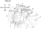
- FIG. 2A and FIG. 2B are a left side view and a top view, respectively, showing the engine 1 and its vicinity. Note that the terms front, rear, left, right, up and down, as used in FIG. 2A and FIG. 2B , refer to these directions with the engine 1 installed on the motorcycle 100.
- the engine 1 is a 4-stroke water-cooled engine.
- the engine 1 includes a crankcase 2, a cylinder body 3, a cylinder head 4, and a cylinder head cover 5, as shown in FIG. 2A and FIG. 2B .
- the crankcase 2 houses a crank shaft 6.
- the crank shaft 6 extends in the left-right direction.
- a transmission case 7 that houses a transmission (e.g., CVT (Continuously Variable Transmission)).
- CVT Continuous Variable Transmission
- the cylinder body 3 is arranged forward of the crankcase 2.
- the cylinder body 3 is coupled to the front portion of the crankcase 2.
- the cylinder head 4 is arranged forward of the cylinder body 3.
- the cylinder head 4 is coupled to the front portion of the cylinder body 3.
- the cylinder head cover 5 is arranged forward of the cylinder head 4.
- the cylinder head cover 5 is coupled to the front portion of the cylinder head 4.
- a dynamic valve mechanism (not shown in FIG. 2 ) including an intake valve, an exhaust valve, a cam shaft, etc., is provided in the cylinder head 4 and the cylinder head cover 5.
- a cylinder (not shown) is formed inside the cylinder body 3.
- the cylinder extends along the cylinder axis CA.
- the cylinder axis CA is significantly tilted forward relative to the vertical direction (the up-down direction). In other words, the cylinder extends forward from the crankcase 2.
- "forward” is herein used in a broad sense and includes both the case where the cylinder extends forward along the horizontal direction and the case where the cylinder is inclined from the horizontal direction.
- the engine 1 herein is a single-cylinder engine having one cylinder, but may also be a multi-cylinder engine having multiple cylinders.
- the cylinder houses a piston (not shown), which is linked to the crank shaft 6 via a connecting rod (not shown).
- a piston (not shown)
- the crankcase 2 may be formed separately or may be formed as a single member.
- An intake passage portion 10 is connected to the cylinder head 4 of the engine 1.
- the intake passage section 10 is arranged upward of the engine 1.
- the intake passage portion 10 includes an intake duct 11 connected to the cylinder head 4 and extending rearward from an upper surface 4a of the cylinder head 4, a throttle body 12 provided at a midpoint along the intake duct 11, an air cleaner (not shown) connected to the intake duct 11, etc.
- the engine 1 further includes a hydraulic tensioner (hereinafter referred to simply as “tensioner”) 20, as shown in FIG. 2A and FIG. 2B .
- tensioner 20 is arranged in the upper portion of the cylinder body 3.
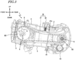
- FIG. 3 is a view showing the interior of the engine 1.
- a cam chain 9 is wound around the crank shaft 6 and a cam shaft 8 (more strictly, a chain drive sprocket 6S attached to the crank shaft 6 and a cam sprocket 8S attached to the cam shaft 8).
- the tensioner 20 applies tension on the cam chain 9.
- the cam chain 9 is an example of the endless transmission member.
- a different endless transmission member e.g., a cam belt
- the tensioner 20 includes a chain guide 21 that contacts the cam chain 9, and a tensioner lifter 22 that presses the chain guide 21 against the cam chain 9.
- An oil pump 40 is arranged in the crankcase 2.
- the oil pump 40 is linked to and driven by the crank shaft 6.
- Oil is supplied to the tensioner 20 from the oil pump 40 via an oil channel 41.
- the oil channel 41 is formed spanning from the crankcase 2 to the cylinder body 3.
- a cylinder gasket is arranged between the crankcase 2 and the cylinder body 3, and a portion 41a of the oil channel 41, which is located between the crankcase 2 and the cylinder body 3, passes through a through hole formed in the cylinder gasket.
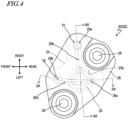
- FIG. 4 is a top view schematically showing the tensioner 20.
- FIG. 5 and FIG. 6 are cross-sectional views schematically showing the tensioner 20, showing cross sections taken along line 5A-5A' and line 6A-6A' of FIG. 4 , respectively.
- FIG. 7 is a perspective view schematically showing the tensioner 20, with the tensioner 20 being partially cut out. In FIG. 4 to FIG. 7 , the chain guide 21 is omitted.
- the tensioner lifter 22 of the tensioner 20 includes a tensioner body 23, a plunger 24, an inner sleeve 25, and a tensioner cap 26.
- a through hole (hereinafter referred to as the "plunger hole”) 23a is formed in the tensioner body 23.
- the plunger hole 23a extends in a direction that is inclined slightly backward from the up-down direction (the vertical direction), as shown in FIG. 5 .
- the lower end of the plunger hole 23a is open to the inside of the engine 1 (inside the cylinder body 3).
- the tensioner body 23 is formed integrally with the cylinder body 3. It can be said that a part of the cylinder body 3 functions as the tensioner body 23. Note that the tensioner body 23 may be separate from the cylinder body 3.
- the plunger 24 has a cylindrical shape, i.e., a bottomed cylindrical shape (more specifically, a bottomed circular cylindrical shape), with one end closed.
- the plunger 24 has an end wall 24a located at the distal end portion (the lower end portion) and a peripheral wall 24b extending from the peripheral edge of the end wall 24a.
- the plunger 24 is inserted into the plunger hole 23a of the tensioner body 23 so that the plunger 24 is movable in the axial direction of the plunger hole 23a.
- the distal end portion (the end wall 24a) of the plunger 24 protrudes from the lower end of the tensioner body 23 into the cylinder body 3 (more specifically, into the cam chain chamber) and contacts the chain guide 21.
- the inner sleeve 25 is a cylindrical shape (more specifically, a circular cylindrical shape).
- the inner sleeve 25 has an end wall 25a located at the distal end portion (lower end portion) and a peripheral wall 25b extending from the peripheral edge of the end wall 25a.
- a through hole (oil hole) 25c is formed in the end wall 25a.
- a recess 25d is formed in the lower surface of the end wall 25a.
- the inner sleeve 25 is inserted inside the plunger 24.
- An annular groove 25e is formed on the outer surface of the inner sleeve 25, and a circlip 27 is attached to the annular groove 25e.
- the tensioner cap 26 is attached to one end portion (here, the upper end portion) of the tensioner body 23.
- the tensioner cap 26 is attached to the tensioner body 23 by a plurality of bolts 28.
- a lower surface 26a of the tensioner cap 26 contacts the proximal end (the upper end) of the inner sleeve 25.
- a tensioner gasket 29 is arranged between the tensioner cap 26 and the tensioner body 23.
- the tensioner 20 has a first hydraulic chamber (high pressure chamber) HC1 and a second hydraulic chamber (low pressure chamber) HC2.
- the first hydraulic chamber HC1 is formed between the inner sleeve 25 and the plunger 24.
- the second hydraulic chamber HC2 is formed inside the inner sleeve 25.
- the second hydraulic chamber HC2 stores the oil to be supplied to the first hydraulic chamber HC1.
- the second hydraulic chamber HC2 is connected to the first hydraulic chamber HC1 via the oil hole 25c.
- a coil spring 31 is arranged inside the first hydraulic chamber HC1.
- the coil spring 31 biases the plunger 24 toward the cam chain 9 (the endless transmission member). That is, the elastic force of the coil spring 31 presses the end wall 24a of the plunger 24 against the chain guide 21.
- the elastic force of the coil spring 31 also acts to press the proximal end of the inner sleeve 25 against the tensioner cap 26.
- the coil spring 31 is an example of the biasing member.
- a biasing member other than the coil spring 31 may be used in place of the coil spring 31.
- a check valve unit 32 is arranged between the first hydraulic chamber HC1 and the second hydraulic chamber HC2.
- the check valve unit 32 has the function of opening and closing the oil hole 25c to allow oil in the second hydraulic chamber HC2 to flow in one direction (from the second hydraulic chamber HC2 to the first hydraulic chamber HC1). That is, the check valve unit 32 prevents the backflow of oil from the first hydraulic chamber HC1 to the second hydraulic chamber HC2.
- the check valve unit 32 includes a check valve 33, a valve seat 34, and a check spring 35.
- the check valve 33 is provided so that the check valve 33 can be brought into close contact with the periphery of the lower side of the oil hole 25c.
- the check valve 33 is herein a ball valve.
- the valve seat 34 is arranged in the recess 25d of the end wall 25a and houses the check valve 33.
- the valve seat 34 has a cup portion 34a formed in a cup shape and a flange portion 34b extending radially outward from the peripheral edge portion on the open side of the cup portion 34a.
- the cup portion 34a has a plurality of small holes (not shown) through which oil passes.
- the check spring 35 is arranged in the valve seat 34 and biases the check valve 33 upward (toward the second hydraulic chamber HC2).
- the check spring 35 is herein a coil spring.
- An oil supply hole 51 and an air vent hole 52 are formed in the tensioner body 23.
- the oil supply hole 51 constitutes a part of the oil channel 41 extending from the oil pump 40, through which the oil supplied to the second hydraulic chamber HC2 passes.
- the oil supply hole 51 includes a portion extending in the up-down direction.
- FIG. 7 shows, by white arrows, the flow of oil in the tensioner 20.
- the air vent hole 52 is a hole for venting air out of the tensioner 20, and running through the tensioner body 23 in the up-down direction.
- FIG. 7 shows the air flow by a hatched arrow.
- tensioner gasket 29 has through holes 29a and 29b that overlap the oil supply hole 51 and the air vent hole 52, respectively, in plan view as viewed from the axial direction of the plunger hole 23a.
- plan view herein means “plan view as viewed from the axial direction of the plunger hole 23a", unless otherwise specified.
- FIG. 8 is a perspective view of the tensioner cap 26 as viewed from the reverse side.
- the lower surface 26a of the tensioner cap 26 has a groove-shaped oil supply channel 26b.
- the oil supply channel 26b extends from the outside to the inside of the outer edge of the plunger 24 (substantially overlapping the inner surface of the plunger hole 23a) in plan view. More specifically, the oil supply channel 26b overlaps the second hydraulic chamber HC2 and the oil supply hole 51 in plan view, and connects between the second hydraulic chamber HC2 and the oil supply hole 51.
- the oil supply channel 26b also overlaps the space S1 enclosed by the inner surface of the plunger hole 23a, the outer surface of the inner sleeve 25, and the proximal end (the upper end) of the plunger 24. In the illustrated example, the oil supply channel 26b extends generally along the left-right direction.
- the lower surface 26a of the tensioner cap 26 further has a plurality of grooves 26c and 26d.
- the plurality of grooves 26c and 26d each connect between the outside of the inner sleeve 25 in the radial direction and the second hydraulic chamber HC2.
- the groove 26c and the groove 26d are continuous (the groove 26c and the groove 26d can be said to be formed as one unit and form a single groove as a whole), but the grooves 26c and 26d may be separate from each other as will be described below.
- the grooves 26c and 26d extend generally along the front-rear direction.
- One 26c of the grooves 26c and 26d is located at a position lower than the other 26d while the engine 1 is in operation (see FIG. 5 ).
- the groove 26c which is located at a relatively low position, will also be referred to as the "first groove”
- the groove 26d which is located at a relatively high position, as the "second groove”.
- first groove 26c and the second groove 26d each connect between the outside of the inner sleeve 25 in the radial direction and the second hydraulic chamber HC2. More specifically, the first groove 26c extends so as to overlap the space S1 and the second hydraulic chamber HC2 in plan view, and connects between the space S1 and the second hydraulic chamber HC2. The second groove 26d extends so as to overlap the second hydraulic chamber HC2 and the air vent hole 52 in plan view, and connects between the second hydraulic chamber HC2 and the air vent hole 52.
- oil supply channel 26b, the first groove 26c and the second groove 26d are continuous with each other in the illustrated example, the oil supply channel 26b, the first groove 26c, and the second groove 26d may be separate from one another, as will be described below.
- the tensioner cap 26 also has a plurality of bolt holes 26e.
- the bolts 28 are inserted into the bolt holes 26e.
- the tensioner 20 having the configuration described above operates as follows.
- the oil pump 40 When the engine 1 starts, the oil pump 40 is activated and the stored oil is supplied by the oil pump 40 to the tensioner 20 via the oil channel 41. Note that oil may also be supplied to other parts of the engine 1 from the oil pump 40.
- the oil supplied to the oil supply hole 51 of the tensioner body 23 flows through the oil supply channel 26b of the tensioner cap 26 into the second hydraulic chamber HC2. Note that the oil supplied to the oil supply hole 51 also flows into the space S1 through the oil supply channel 26b. Since the space S1 extends along the circumferential direction of the plunger hole 23a, the oil that flows into the space S1 flows into the second hydraulic chamber HC2 through the first groove 26c of the tensioner cap 26.
- the lower surface 26a of the tensioner cap 26 (the surface in contact with the proximal end of the inner sleeve 25) has the first groove 26c and the second groove 26d that each connect between the outside of the inner sleeve 25 in the radial direction and the second hydraulic chamber HC2, thereby separating between air venting from the second hydraulic chamber HC2, which is the internal space of the inner sleeve 25, and oil inflow into the second hydraulic chamber HC2. Therefore, it is possible to smoothly perform air venting from the second hydraulic chamber HC2 and oil filling into the second hydraulic chamber HC2.
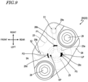
- FIG. 9 is a top view schematically showing the tensioner 20, as is FIG. 4 .
- first intersection refers to a portion P1 on the lower surface 26a of the tensioner cap 26 where the oil supply channel 26b intersects with the projection of the outer edge of the plunger 24 onto the first surface 26a
- second intersection refers to a portion P2 where the second groove 26d intersects with the projection of the outer edge of the plunger 24 onto the first surface 26a.
- a portion P3 of the proximal end of the inner sleeve 25 that overlaps the first groove 26c in plan view is located at a position lower than the first intersection P1 and the second intersection P2 while the engine 1 is in operation.
- the second intersection P2 is located at a position higher than the first intersection P1 while the engine 1 is in operation. Thus, it is possible to even more desirably perform air venting from the second hydraulic chamber HC2.
- the second groove 26d overlaps, in plan view, the highest point HP of the proximal end of the inner sleeve 25 while the engine 1 is in operation.
- the highest point HP of the proximal end of the inner sleeve 25 air remaining or mixed in the second hydraulic chamber HC2 is more likely to vent spontaneously.
- the first groove 26c overlaps, in plan view, the lowest point LP of the proximal end of the inner sleeve 25 while the engine 1 is in operation.
- the lowest point LP of the proximal end of the inner sleeve 25 oil supplied from the outside of the inner sleeve 25 overcomes the end surface of the inner sleeve 25 even with a relatively low oil surface, and oil is more likely to flow into the second hydraulic chamber HC2.
- the oil supply channel 26b may be separated from the first groove 26c and the second groove 26d, as shown in FIG. 10 and FIG. 11 .
- the oil supply channel 26b extends from the oil supply hole 51 to the space S1 but not to the second hydraulic chamber HC2. Therefore, the oil supplied to the oil supply hole 51 does not flow directly from the oil supply channel 26b to the second hydraulic chamber HC2, but flows into the second hydraulic chamber HC2 via the space S1 and the first groove 26c.
- the advantage is that the oil supplied to the space S1 (outside the inner sleeve 25) and the air mixed therewith are likely to be separated.
- the advantage is that the oil supplied from the oil pump 40 reaches the second hydraulic chamber HC2 more quickly when the engine 1 is restarted.
- the first groove 26c and the second groove 26d may be separated from each other as shown in FIG. 12 and FIG. 13 .
- the advantage is that when the engine 1 is restarted, oil stored in the space S1 (outside the inner sleeve 25) is suppressed from passing through the upper portion of the second hydraulic chamber HC2 to be discharged directly from the air vent hole 52 of the tensioner body 23.
- the advantage is that air accumulation in the discontinuity between grooves (the portion located between the first groove 26c and the second groove 26d in the example shown in FIG. 12 and FIG. 13 ) is eliminated, and it is possible to more smoothly supply oil to the second hydraulic chamber HC2.
- the lower surface 26a of the tensioner cap 26 may have a further groove that connects between the outside of the inner sleeve 25 in the radial direction and the second hydraulic chamber HC2. That is, the lower surface 26a of the tensioner cap 26 may have three or more grooves that connect between the outside of the inner sleeve 25 in the radial direction and the second hydraulic chamber HC2.
- the hydraulic tensioner 20 is the hydraulic tensioner 20 for applying tension on the endless transmission member 9 wound around the crank shaft 6 and the cam shaft 8 of the internal combustion engine 1, the hydraulic tensioner 20 including: the tensioner body 23 having the through hole 23a formed therein; the bottomed cylindrical plunger 24 movably inserted into the through hole 23a of the tensioner body 23 in the axial direction of the through hole 23a, the cylindrical inner sleeve 25 inserted inside the plunger 24; and the tensioner cap 26 attached to one end of the tensioner body 23 and having the first surface 26a in contact with the proximal end of the inner sleeve 25.
- the first hydraulic chamber HC1 is formed between the inner sleeve 25 and the plunger 24, and the second hydraulic chamber HC2 that stores oil to be supplied to the first hydraulic chamber HC1 is formed inside the inner sleeve 25.
- the first surface 26a of the tensioner cap 26 has a plurality of grooves 26c and 26d that each connect between the outside of the inner sleeve 25 in the radial direction and the second hydraulic chamber HC2.
- the surface (the first surface) 26a of the tensioner cap 26 that contacts the proximal end of the inner sleeve 25 has a plurality of grooves 26c and 26d that each connect between the outside of the inner sleeve 25 in the radial direction and the second hydraulic chamber HC2, thereby separating between air venting from the second hydraulic chamber HC2, which is the internal space of the inner sleeve 25, and oil inflow into the second hydraulic chamber HC2. Therefore, it is possible to smoothly perform air venting from the second hydraulic chamber HC2 and oil filling into the second hydraulic chamber HC2.
- the first surface 26a of the tensioner cap 26 has the groove-shaped oil supply channel 26b extending from outside to inside of the outer edge of the plunger 24 in plan view as viewed from the axial direction.
- the first groove refers to the groove 26c of the plurality of grooves 26c and 26d that is located at a lowest position while the internal combustion engine 1 is in operation
- the first intersection refers to the portion P1 on the first surface 26a where the oil supply channel 26b intersects with the projection of the outer edge of the plunger 24 onto the first surface 26a
- the second intersection refers to the portion P2 on the first surface 26a where the groove 26d of the plurality of grooves 26c and 26d other than the first groove 26c intersects with the projection of the outer edge of the plunger 24 onto the first surface 26a
- the portion P3 of the proximal end of the inner sleeve 25 that overlaps the first groove 26c in plan view as viewed from the axial direction is located at a position lower than the first intersection P1 and the second intersection
- first groove refers to the groove 26c, of the plurality of grooves 26c and 26d of the tensioner cap 26, that is located at a lowest position
- first intersection refers to the portion P1 on the first surface 26a where the oil supply channel 26b intersects with the projection of the outer edge of the plunger 24 onto the first surface 26a
- second intersection refers to the portion P2 on the first surface 26a where the groove 26d of the plurality of grooves 26c and 26d other than the first groove 26c intersects with the projection of the outer edge of the plunger 24 onto the first surface 26a
- a portion of the proximal end of the inner sleeve 25 that overlaps the first groove 26c in plan view as viewed from the axial direction is located at a position lower than the first intersection P1 and the second intersection P2 while the internal combustion engine 1 is in operation.
- oil that leaks out of the leak gap of the tensioner 20 (the gap between the inner surface of the plunger 24 and the outer surface of the inner sleeve 25) and accumulates on the outside of the inner sleeve 25 when the oil supplied by the oil pump 40 has not yet reached the vicinity of the tensioner 20, such as when restarting the internal combustion engine 1, can be made to overcome the end surface of the inner sleeve 25 to be re-supplied to the inside of the inner sleeve 25 (i.e., into the second hydraulic chamber HC2), thereby suppressing air from being mixed into the first hydraulic chamber HC1.
- the first surface 26a of the tensioner cap 26 has the groove-shaped oil supply channel 26b extending from outside to inside of the outer edge of the plunger 24 in plan view as viewed from the axial direction.
- the first groove refers to the groove 26c of the plurality of grooves 26c and 26d that is located at a lowest position while the internal combustion engine 1 is in operation
- the first intersection refers to the portion P1 on the first surface 26a where the oil supply channel 26b intersects with the projection of the outer edge of the plunger 24 onto the first surface 26a
- the second intersection refers to the portion P2 on the first surface 26a where the groove 26d of the plurality of grooves 26c and 26d other than the first groove 26c intersects with the projection of the outer edge of the plunger 24 onto the first surface 26a
- the second intersection P2 is located at a position higher than the first intersection P1 while the internal combustion engine 1 is in operation.
- first groove refers to the groove 26c, of the plurality of grooves 26c and 26d of the tensioner cap 26, that is located at a lowest position
- first intersection refers to the portion P1 on the first surface 26a where the oil supply channel 26b intersects with the projection of the outer edge of the plunger 24 onto the first surface 26a
- second intersection refers to the portion P2 on the first surface 26a where the groove 26d of the plurality of grooves 26c and 26d other than the first groove 26c intersects with the projection of the outer edge of the plunger 24 onto the first surface 26a
- the second intersection P2 is located at a position higher than the first intersection P1 while the internal combustion engine 1 is in operation.
- At least one of the plurality of grooves 26c and 26d overlaps, in plan view as viewed from the axial direction, the highest point HP of the proximal end of the inner sleeve 25 while the internal combustion engine 1 is in operation.
- At least one of the plurality of grooves 26c and 26d overlaps, in plan view as viewed from the axial direction, the lowest point LP of the proximal end of the inner sleeve 25 while the internal combustion engine 1 is in operation.
- the hydraulic tensioner 20 further includes the biasing member 31 that is arranged inside the first hydraulic chamber HC1 and biases the plunger 24 toward the endless transmission member 9, and the check valve unit 32 arranged between the first hydraulic chamber HC1 and the second hydraulic chamber HC2.
- the first surface 26a of the tensioner cap 26 has the groove-shaped oil supply channel 26b extending from outside to inside of the outer edge of the plunger 24 in plan view as viewed from the axial direction, wherein the oil supply channel 26b and plurality of grooves 26c and 26d are continuous with each other.
- the advantage is that the oil supplied by the oil pump 40 reaches the second hydraulic chamber HC2 more quickly when the internal combustion engine 1 is restarted.
- the first surface 26a of the tensioner cap 26 has the groove-shaped oil supply channel 26b extending from outside to inside of the outer edge of the plunger 24 in plan view as viewed from the axial direction, and the oil supply channel 26b and the plurality of grooves 26c and 26d are separated from each other.
- the advantage is that the oil supplied to the outside of the inner sleeve 25 (the space S1 enclosed by the inner surface of the plunger hole 23a, the outer surface of the inner sleeve 25 and the proximal end (the upper end) of the plunger 24) and the air mixed therewith are likely to be separated.
- the plurality of grooves 26c and 26d include two grooves 26c and 26d that are continuous with each other.
- the advantage is that air accumulation in the discontinuity between grooves is eliminated, and it is possible to more smoothly supply oil to the second hydraulic chamber HC2.
- the plurality of grooves 26c and 26d include two grooves 26c and 26d that are separated from each other.
- the advantage is that when the internal combustion engine 1 is restarted, oil stored on the outside of the inner sleeve 25 (in the space S1 described above) is suppressed from passing through the upper portion of the second hydraulic chamber HC2 to be discharged directly from the air vent hole of the tensioner body 23.
- the internal combustion engine 1 includes the hydraulic tensioner 20 having any of the configurations described above.
- the straddled vehicle 100 includes the internal combustion engine 1 having the configuration described above.
- a hydraulic tensioner capable of desirably performing both air venting from the hydraulic chamber and oil filling into the hydraulic chamber.
- the hydraulic tensioner according to the preferred embodiment is preferably used in internal combustion engines of various straddled vehicles.
Landscapes
- Engineering & Computer Science (AREA)
- General Engineering & Computer Science (AREA)
- Mechanical Engineering (AREA)
- Devices For Conveying Motion By Means Of Endless Flexible Members (AREA)
Abstract
Description
- The present invention relates to a hydraulic tensioner, an internal combustion engine, and a straddled vehicle.
- Internal combustion engines have been known in the art that have a tensioner that applies tension on a cam chain by pressing the cam chain. Examples of the tensioner include mechanical tensioners. A mechanical tensioner is disclosed in
JP 2020-148132 A - The tensioner disclosed in
JP 2020-148132 A - Tensioners known in the art include hydraulic tensioners. Hydraulic tensioners are generally superior to mechanical tensioners in terms of noise suppression and durability. Hydraulic tensioners are required to desirably perform both air venting from the hydraulic chamber and oil filling into the hydraulic chamber. If these are not performed desirably, there is a risk that the pressing force of the tensioner will be insufficient (i.e., the tensioner will not be sufficiently engaged with the cam chain). Insufficient pressing force of the tensioner can cause mechanical noise due to deteriorated behavior of the cam chain.
- It is an object of the present invention to provide a hydraulic tensioner capable of desirably performing both air venting from the hydraulic chamber and oil filling into the hydraulic chamber. According to the present invention said object is solved by a hydraulic tensioner having the features of
independent claim 1. Preferred embodiments are laid down in the dependent claims. - The present specification discloses a hydraulic tensioner, an internal combustion engine, and a straddled vehicle as set forth in the following items.
- A hydraulic tensioner for applying tension on an endless transmission member wound around a crank shaft and a cam shaft of an internal combustion engine, including:
- a tensioner body having a through hole formed therein;
- a bottomed cylindrical plunger inserted into the through hole of the tensioner body so that the cylindrical plunger is movable in an axial direction of the through hole;
- a cylindrical inner sleeve inserted inside the plunger; and
- a tensioner cap attached to one end of the tensioner body and having a first surface in contact with a proximal end of the inner sleeve, wherein:
- a first hydraulic chamber is formed between the inner sleeve and the plunger, and a second hydraulic chamber that stores oil to be supplied to the first hydraulic chamber is formed inside the inner sleeve; and
- the first surface of the tensioner cap has a plurality of grooves that each connect between outside of the inner sleeve in a radial direction and the second hydraulic chamber.
- With the hydraulic tensioner according to a preferred embodiment, the surface (the first surface) of the tensioner cap in contact with the proximal end of the inner sleeve has a plurality of grooves that each connects between the outside of the inner sleeve in the radial direction and the second hydraulic chamber, thereby separating between air venting from the second hydraulic chamber, which is the internal space of the inner sleeve, and oil inflow into the second hydraulic chamber. Therefore, it is possible to smoothly perform air venting from the second hydraulic chamber and oil filling into the second hydraulic chamber. In contrast, if only one groove is formed on the first surface of the tensioner cap that connects between the outside of the inner sleeve in the radial direction and the second hydraulic chamber, air venting from the second hydraulic chamber and oil inflow into the second hydraulic chamber are not separated, making it difficult for air to vent from the second hydraulic chamber and the oil becomes slightly clogged and is difficult to flow into the second hydraulic chamber.
- According to a preferred embodiment, it is possible to desirably perform air venting from the second hydraulic chamber and oil filling into the second hydraulic chamber, thereby suppressing air from being mixed into the first hydraulic chamber. Thus, it is possible to suppress the pressing force of the tensioner from becoming insufficient (which may cause mechanical noise due to deteriorated behavior of the cam chain).
- The hydraulic tensioner according to
Item 1, wherein: - the first surface of the tensioner cap has a groove-shaped oil supply channel extending from outside to inside of an outer edge of the plunger in plan view as viewed from the axial direction; and
- where:
- a first groove refers to one of the plurality of grooves that is located at a lowest position while the internal combustion engine is in operation;
- a first intersection refers to a portion on the first surface where the oil supply channel intersects with a projection of the outer edge of the plunger onto the first surface; and
- a second intersection refers to a portion on the first surface where one of the plurality of grooves other than the first groove intersects with the projection of the outer edge of the plunger onto the first surface,
- a portion of the proximal end of the inner sleeve that overlaps the first groove in plan view as viewed from the axial direction is located at a position lower than the first intersection and the second intersection while the internal combustion engine is in operation.
- Where the "first groove" refers to one of the plurality of grooves of the tensioner cap that is located at the lowest position, the "first intersection" refers to a portion on the first surface where the oil supply channel intersects with the projection of the outer edge of the plunger onto the first surface, and the "second intersection" refers to a portion on the first surface where one of the plurality of grooves other than the first groove intersects with the projection of the outer edge of the plunger onto the first surface, it is preferred that a portion of the proximal end of the inner sleeve that overlaps the first groove in plan view as viewed from the axial direction is located at a position lower than the first intersection and the second intersection while the internal combustion engine is in operation.
- Therefore, oil that leaks out of the leak gap of the tensioner (the gap between the inner surface of the plunger and the outer surface of the inner sleeve) and accumulates on the outside of the inner sleeve when the oil supplied by the oil pump has not yet reached the vicinity of the tensioner, such as when restarting the internal combustion engine, can be made to overcome the end surface of the inner sleeve to be re-supplied to the inside of the inner sleeve (i.e., into the second hydraulic chamber), thereby suppressing air from being mixed into the first hydraulic chamber. Thus, it is possible to extend the load holding time, thereby suppressing the pressing force of the tensioner from becoming insufficient such as when restarting the internal combustion engine.
- The hydraulic tensioner according to
Item - the first surface of the tensioner cap has a groove-shaped oil supply channel extending from outside to inside of an outer edge of the plunger in plan view as viewed from the axial direction; and
- where:
- a first groove refers to one of the plurality of grooves that is located at a lowest position while the internal combustion engine is in operation;
- a first intersection refers to a portion on the first surface where the oil supply channel intersects with a projection of the outer edge of the plunger onto the first surface; and
- a second intersection refers to a portion on the first surface where one of the plurality of grooves other than the first groove intersects with the projection of the outer edge of the plunger onto the first surface,
- the second intersection is located at a position higher than the first intersection while the internal combustion engine is in operation.
- Where the "first groove" refers to one of the plurality of grooves of the tensioner cap that is located at a lowest position, the "first intersection" refers to a portion on the first surface where the oil supply channel intersects with the projection of the outer edge of the plunger onto the first surface, and the "second intersection" refers to a portion on the first surface where one of the plurality of grooves other than the first groove intersects with the projection of the outer edge of the plunger onto the first surface, it is preferred that the second intersection is located at a position higher than the first intersection while the internal combustion engine is in operation. Thus, it is possible to even more desirably perform air venting from the second hydraulic chamber.
- The hydraulic tensioner according to any one of
Items 1 to 3, wherein at least one of the plurality of grooves overlaps, in plan view as viewed from the axial direction, a highest point of the proximal end of the inner sleeve while the internal combustion engine is in operation. - With at least one groove of the tensioner cap overlapping, in plan view, the highest point of the proximal end of the inner sleeve, air remaining or mixed in the second hydraulic chamber is more likely to vent spontaneously.
- The hydraulic tensioner according to any one of
Items 1 to 4, wherein at least one of the plurality of grooves overlaps, in plan view as viewed from the axial direction, a lowest point of the proximal end of the inner sleeve while the internal combustion engine is in operation. - With at least one groove of the tensioner cap overlapping the lowest point of the proximal end of the inner sleeve in plan view, oil supplied from the outside of the inner sleeve overcomes the end surface of the inner sleeve even with a relative low oil surface, and oil is more likely to flow into the second hydraulic chamber.
- The hydraulic tensioner according to any one of
Items 1 to 5, further including: - a biasing member that is arranged inside the first hydraulic chamber and biases the plunger toward the endless transmission member; and
- a check valve unit arranged between the first hydraulic chamber and the second hydraulic chamber.
- The hydraulic tensioner according to any one of
Items 1 to 6, wherein: - the first surface of the tensioner cap has a groove-shaped oil supply channel extending from outside to inside of the outer edge of the plunger in plan view as viewed from the axial direction; and
- the oil supply channel and the plurality of grooves are continuous with each other.
- With the oil supply channel and the plurality of grooves being continuous with each other, the advantage is that the oil supplied by the oil pump reaches the second hydraulic chamber more quickly when the internal combustion engine is restarted.
- The hydraulic tensioner according to any one of
Items 1 to 6, wherein: - the first surface of the tensioner cap has a groove-shaped oil supply channel extending from outside to inside of the outer edge of the plunger in plan view as viewed from the axial direction; and
- the oil supply channel and the plurality of grooves are separated from each other.
- With the oil supply channel and the plurality of grooves being separated from each other, the advantage is that the oil supplied to the outside of the inner sleeve (the space enclosed by the inner surface of the plunger hole, the outer surface of the inner sleeve and the proximal end (the upper end) of the plunger) and the air mixed therewith are likely to be separated.
- The hydraulic tensioner according to any one of
Items 1 to 8, wherein the plurality of grooves include two grooves that are continuous with each other. - With two grooves being continuous with each other, the advantage is that air accumulation in the discontinuity between grooves is eliminated, and it is possible to more smoothly supply oil to the second hydraulic chamber.
- The hydraulic tensioner according to any one of
Items 1 to 8, wherein the plurality of grooves include two grooves that are separated from each other. - With two grooves being separated from each other, the advantage is that when the internal combustion engine is restarted, oil stored on the outside of the inner sleeve (in the space described above) is suppressed from passing through the upper portion of the second hydraulic chamber to be discharged directly from the air vent hole of the tensioner body.
- An internal combustion engine including the hydraulic tensioner according to any one of
Items 1 to 10. - A straddled vehicle including the internal combustion engine according to
Item 11. - According to a preferred embodiment, there is provided a hydraulic tensioner capable of desirably performing both air venting from the hydraulic chamber and oil filling into the hydraulic chamber.
-
-
FIG. 1 is a left side view schematically showing amotorcycle 100. -
FIG. 2A is a left side view showing anengine 1 of themotorcycle 100 and its vicinity. -
FIG. 2B is a top view showing theengine 1 and its vicinity. -
FIG. 3 is a view showing the interior of theengine 1. -
FIG. 4 is a top view schematically showing atensioner 20. -
FIG. 5 is a cross-sectional view schematically showing thetensioner 20, showing a cross-section taken alongline 5A-5A' ofFIG. 4 . -
FIG. 6 is a cross-sectional view schematically showing thetensioner 20, showing a cross-section taken alongline 6A-6A' ofFIG. 4 . -
FIG. 7 is a perspective view schematically showing thetensioner 20, with thetensioner 20 being partially cut out. -
FIG. 8 is a perspective view of atensioner cap 26 as viewed from the reverse side. -
FIG. 9 is a top view schematically showing thetensioner 20. -
FIG. 10 is a top view schematically showing thetensioner 20, showing another example of the configuration of thetensioner 20. -
FIG. 11 is a cross-sectional view taken alongline 11A-11A' ofFIG. 10 . -
FIG. 12 is a top view schematically showing thetensioner 20, showing yet another example of the configuration of thetensioner 20. -
FIG. 13 is a view showing a cross section taken alongline 13A-13A' ofFIG. 12 . - A straddled vehicle according to a preferred embodiment will now be described with reference to the drawings. A straddled vehicle is a vehicle that is straddled by a passenger. In the following description, a motorcycle will be illustrated as the straddled vehicle according to the preferred embodiment. The type of motorcycle is not limited in any way and can be any of the so-called scooter type, moped type, off-road type, on-road type, etc. The straddled vehicle according to the present teaching is not limited to a motorcycle, but may also be an ATV (All Terrain Vehicle), a four-wheeled buggy, etc.
- Referring to
FIG. 1 , the general configuration of amotorcycle 100 of the present embodiment will be described.FIG. 1 is a left side view schematically showing themotorcycle 100. The terms front, rear, left, right, up and down, as used in the description below, refer to these directions as seen from a virtual passenger seated on a seat of themotorcycle 100. The terms up and down refer to these directions in the vertical direction while themotorcycle 100 is stationary on a horizontal plane. These directions are used also when describing the various parts of the engine. Thus, front, rear, left, right, up and down in the engine refer to these directions with the engine installed on themotorcycle 100. - As shown in
FIG. 1 , themotorcycle 100 includes avehicle body frame 102 including ahead pipe 101, aseat 103 supported on thevehicle body frame 102, an engine (internal combustion engine) 1 supported on thevehicle body frame 102, asteering handle 104 pivotably supported on thehead pipe 101, afront wheel 105, and arear wheel 106 driven by theengine 1. - Referring to
FIG. 2A andFIG. 2B , the configuration of theengine 1 will be described.FIG. 2A andFIG. 2B are a left side view and a top view, respectively, showing theengine 1 and its vicinity. Note that the terms front, rear, left, right, up and down, as used inFIG. 2A andFIG. 2B , refer to these directions with theengine 1 installed on themotorcycle 100. - The
engine 1 is a 4-stroke water-cooled engine. Theengine 1 includes acrankcase 2, acylinder body 3, acylinder head 4, and acylinder head cover 5, as shown inFIG. 2A andFIG. 2B . - The
crankcase 2 houses acrank shaft 6. Thecrank shaft 6 extends in the left-right direction. To the left of thecrankcase 2 is arranged atransmission case 7 that houses a transmission (e.g., CVT (Continuously Variable Transmission)). - The
cylinder body 3 is arranged forward of thecrankcase 2. Thecylinder body 3 is coupled to the front portion of thecrankcase 2. - The
cylinder head 4 is arranged forward of thecylinder body 3. Thecylinder head 4 is coupled to the front portion of thecylinder body 3. - The
cylinder head cover 5 is arranged forward of thecylinder head 4. Thecylinder head cover 5 is coupled to the front portion of thecylinder head 4. - A dynamic valve mechanism (not shown in
FIG. 2 ) including an intake valve, an exhaust valve, a cam shaft, etc., is provided in thecylinder head 4 and thecylinder head cover 5. - A cylinder (not shown) is formed inside the
cylinder body 3. The cylinder extends along the cylinder axis CA. The cylinder axis CA is significantly tilted forward relative to the vertical direction (the up-down direction). In other words, the cylinder extends forward from thecrankcase 2. Note that "forward" is herein used in a broad sense and includes both the case where the cylinder extends forward along the horizontal direction and the case where the cylinder is inclined from the horizontal direction. Note that theengine 1 herein is a single-cylinder engine having one cylinder, but may also be a multi-cylinder engine having multiple cylinders. - The cylinder houses a piston (not shown), which is linked to the crank
shaft 6 via a connecting rod (not shown). Note that thecylinder body 3 and thecrankcase 2 may be formed separately or may be formed as a single member. - An
intake passage portion 10 is connected to thecylinder head 4 of theengine 1. Theintake passage section 10 is arranged upward of theengine 1. Theintake passage portion 10 includes anintake duct 11 connected to thecylinder head 4 and extending rearward from anupper surface 4a of thecylinder head 4, athrottle body 12 provided at a midpoint along theintake duct 11, an air cleaner (not shown) connected to theintake duct 11, etc. - The
engine 1 further includes a hydraulic tensioner (hereinafter referred to simply as "tensioner") 20, as shown inFIG. 2A andFIG. 2B . Thetensioner 20 is arranged in the upper portion of thecylinder body 3. -
FIG. 3 is a view showing the interior of theengine 1. As shown inFIG. 3 , inside theengine 1, a cam chain 9 is wound around thecrank shaft 6 and a cam shaft 8 (more strictly, achain drive sprocket 6S attached to the crankshaft 6 and acam sprocket 8S attached to the cam shaft 8). Thetensioner 20 applies tension on the cam chain 9. Note that the cam chain 9 is an example of the endless transmission member. A different endless transmission member (e.g., a cam belt) may be used instead of the cam chain 9. - The
tensioner 20 includes achain guide 21 that contacts the cam chain 9, and atensioner lifter 22 that presses thechain guide 21 against the cam chain 9. - An
oil pump 40 is arranged in thecrankcase 2. Theoil pump 40 is linked to and driven by thecrank shaft 6. Oil is supplied to thetensioner 20 from theoil pump 40 via anoil channel 41. Theoil channel 41 is formed spanning from thecrankcase 2 to thecylinder body 3. Although not shown here, a cylinder gasket is arranged between thecrankcase 2 and thecylinder body 3, and aportion 41a of theoil channel 41, which is located between thecrankcase 2 and thecylinder body 3, passes through a through hole formed in the cylinder gasket. - Referring to
FIG. 4 to FIG. 7 , the structure of thetensioner 20 will now be described more specifically.FIG. 4 is a top view schematically showing thetensioner 20.FIG. 5 andFIG. 6 are cross-sectional views schematically showing thetensioner 20, showing cross sections taken alongline 5A-5A' andline 6A-6A' ofFIG. 4 , respectively.FIG. 7 is a perspective view schematically showing thetensioner 20, with thetensioner 20 being partially cut out. InFIG. 4 to FIG. 7 , thechain guide 21 is omitted. - As shown in
FIG. 4 to FIG. 7 , thetensioner lifter 22 of thetensioner 20 includes atensioner body 23, aplunger 24, aninner sleeve 25, and atensioner cap 26. - A through hole (hereinafter referred to as the "plunger hole") 23a is formed in the
tensioner body 23. Theplunger hole 23a extends in a direction that is inclined slightly backward from the up-down direction (the vertical direction), as shown inFIG. 5 . The lower end of theplunger hole 23a is open to the inside of the engine 1 (inside the cylinder body 3). Thetensioner body 23 is formed integrally with thecylinder body 3. It can be said that a part of thecylinder body 3 functions as thetensioner body 23. Note that thetensioner body 23 may be separate from thecylinder body 3. - The
plunger 24 has a cylindrical shape, i.e., a bottomed cylindrical shape (more specifically, a bottomed circular cylindrical shape), with one end closed. Theplunger 24 has anend wall 24a located at the distal end portion (the lower end portion) and aperipheral wall 24b extending from the peripheral edge of theend wall 24a. Theplunger 24 is inserted into theplunger hole 23a of thetensioner body 23 so that theplunger 24 is movable in the axial direction of theplunger hole 23a. The distal end portion (theend wall 24a) of theplunger 24 protrudes from the lower end of thetensioner body 23 into the cylinder body 3 (more specifically, into the cam chain chamber) and contacts thechain guide 21. - The
inner sleeve 25 is a cylindrical shape (more specifically, a circular cylindrical shape). Theinner sleeve 25 has anend wall 25a located at the distal end portion (lower end portion) and aperipheral wall 25b extending from the peripheral edge of theend wall 25a. A through hole (oil hole) 25c is formed in theend wall 25a. Arecess 25d is formed in the lower surface of theend wall 25a. Theinner sleeve 25 is inserted inside theplunger 24. Anannular groove 25e is formed on the outer surface of theinner sleeve 25, and acirclip 27 is attached to theannular groove 25e. - The
tensioner cap 26 is attached to one end portion (here, the upper end portion) of thetensioner body 23. In the illustrated example, thetensioner cap 26 is attached to thetensioner body 23 by a plurality ofbolts 28. Alower surface 26a of thetensioner cap 26 contacts the proximal end (the upper end) of theinner sleeve 25. Atensioner gasket 29 is arranged between thetensioner cap 26 and thetensioner body 23. - The
tensioner 20 has a first hydraulic chamber (high pressure chamber) HC1 and a second hydraulic chamber (low pressure chamber) HC2. The first hydraulic chamber HC1 is formed between theinner sleeve 25 and theplunger 24. The second hydraulic chamber HC2 is formed inside theinner sleeve 25. The second hydraulic chamber HC2 stores the oil to be supplied to the first hydraulic chamber HC1. The second hydraulic chamber HC2 is connected to the first hydraulic chamber HC1 via theoil hole 25c. - A
coil spring 31 is arranged inside the first hydraulic chamber HC1. Thecoil spring 31 biases theplunger 24 toward the cam chain 9 (the endless transmission member). That is, the elastic force of thecoil spring 31 presses theend wall 24a of theplunger 24 against thechain guide 21. The elastic force of thecoil spring 31 also acts to press the proximal end of theinner sleeve 25 against thetensioner cap 26. Note that thecoil spring 31 is an example of the biasing member. A biasing member other than thecoil spring 31 may be used in place of thecoil spring 31. - A
check valve unit 32 is arranged between the first hydraulic chamber HC1 and the second hydraulic chamber HC2. Thecheck valve unit 32 has the function of opening and closing theoil hole 25c to allow oil in the second hydraulic chamber HC2 to flow in one direction (from the second hydraulic chamber HC2 to the first hydraulic chamber HC1). That is, thecheck valve unit 32 prevents the backflow of oil from the first hydraulic chamber HC1 to the second hydraulic chamber HC2. - The
check valve unit 32 includes acheck valve 33, avalve seat 34, and acheck spring 35. - The
check valve 33 is provided so that thecheck valve 33 can be brought into close contact with the periphery of the lower side of theoil hole 25c. Thecheck valve 33 is herein a ball valve. - The
valve seat 34 is arranged in therecess 25d of theend wall 25a and houses thecheck valve 33. Thevalve seat 34 has acup portion 34a formed in a cup shape and aflange portion 34b extending radially outward from the peripheral edge portion on the open side of thecup portion 34a. Thecup portion 34a has a plurality of small holes (not shown) through which oil passes. - The
check spring 35 is arranged in thevalve seat 34 and biases thecheck valve 33 upward (toward the second hydraulic chamber HC2). Thecheck spring 35 is herein a coil spring. - An
oil supply hole 51 and anair vent hole 52 are formed in thetensioner body 23. Theoil supply hole 51 constitutes a part of theoil channel 41 extending from theoil pump 40, through which the oil supplied to the second hydraulic chamber HC2 passes. Theoil supply hole 51 includes a portion extending in the up-down direction.FIG. 7 shows, by white arrows, the flow of oil in thetensioner 20. Theair vent hole 52 is a hole for venting air out of thetensioner 20, and running through thetensioner body 23 in the up-down direction.FIG. 7 shows the air flow by a hatched arrow. Note that thetensioner gasket 29 has throughholes oil supply hole 51 and theair vent hole 52, respectively, in plan view as viewed from the axial direction of theplunger hole 23a. In the following description, "plan view" herein means "plan view as viewed from the axial direction of theplunger hole 23a", unless otherwise specified. - Referring also to
FIG. 8 , the structure of thetensioner cap 26 will now be described.FIG. 8 is a perspective view of thetensioner cap 26 as viewed from the reverse side. - The
lower surface 26a of thetensioner cap 26 has a groove-shapedoil supply channel 26b. As shown inFIG. 4 , etc., theoil supply channel 26b extends from the outside to the inside of the outer edge of the plunger 24 (substantially overlapping the inner surface of theplunger hole 23a) in plan view. More specifically, theoil supply channel 26b overlaps the second hydraulic chamber HC2 and theoil supply hole 51 in plan view, and connects between the second hydraulic chamber HC2 and theoil supply hole 51. Theoil supply channel 26b also overlaps the space S1 enclosed by the inner surface of theplunger hole 23a, the outer surface of theinner sleeve 25, and the proximal end (the upper end) of theplunger 24. In the illustrated example, theoil supply channel 26b extends generally along the left-right direction. - The
lower surface 26a of thetensioner cap 26 further has a plurality ofgrooves grooves inner sleeve 25 in the radial direction and the second hydraulic chamber HC2. Note that in the illustrated example, thegroove 26c and thegroove 26d are continuous (thegroove 26c and thegroove 26d can be said to be formed as one unit and form a single groove as a whole), but thegrooves grooves - One 26c of the
grooves engine 1 is in operation (seeFIG. 5 ). Hereinafter, thegroove 26c, which is located at a relatively low position, will also be referred to as the "first groove", and thegroove 26d, which is located at a relatively high position, as the "second groove". - As already explained, the
first groove 26c and thesecond groove 26d each connect between the outside of theinner sleeve 25 in the radial direction and the second hydraulic chamber HC2. More specifically, thefirst groove 26c extends so as to overlap the space S1 and the second hydraulic chamber HC2 in plan view, and connects between the space S1 and the second hydraulic chamber HC2. Thesecond groove 26d extends so as to overlap the second hydraulic chamber HC2 and theair vent hole 52 in plan view, and connects between the second hydraulic chamber HC2 and theair vent hole 52. - Note that while the
oil supply channel 26b, thefirst groove 26c and thesecond groove 26d are continuous with each other in the illustrated example, theoil supply channel 26b, thefirst groove 26c, and thesecond groove 26d may be separate from one another, as will be described below. - The
tensioner cap 26 also has a plurality ofbolt holes 26e. Thebolts 28 are inserted into thebolt holes 26e. - The
tensioner 20 having the configuration described above operates as follows. - When the
engine 1 starts, theoil pump 40 is activated and the stored oil is supplied by theoil pump 40 to thetensioner 20 via theoil channel 41. Note that oil may also be supplied to other parts of theengine 1 from theoil pump 40. - As shown in
FIG. 7 , the oil supplied to theoil supply hole 51 of thetensioner body 23 flows through theoil supply channel 26b of thetensioner cap 26 into the second hydraulic chamber HC2. Note that the oil supplied to theoil supply hole 51 also flows into the space S1 through theoil supply channel 26b. Since the space S1 extends along the circumferential direction of theplunger hole 23a, the oil that flows into the space S1 flows into the second hydraulic chamber HC2 through thefirst groove 26c of thetensioner cap 26. - In the second hydraulic chamber HC2, the pressure increases due to the oil that has flowed into the second hydraulic chamber HC2, so the
check valve 33 of thecheck valve unit 32 comes off the edge of theoil hole 25c and the oil in the second hydraulic chamber HC2 flows into the first hydraulic chamber HC1 through theoil hole 25c. As a result, the pressure in the first hydraulic chamber HC1 gradually increases. This increase in pressure and the biasing force of thecoil spring 31 cause theplunger 24 to lower and press thechain guide 21 against the cam chain 9. This provides tension on the cam chain 9. - When the movement of the cam chain 9 pushes back the
plunger 24 to reduce the volume of the first hydraulic chamber HC1, some oil in the first hydraulic chamber HC1 passes through the gap between the inner surface of theplunger 24 and the outer surface of the inner sleeve 25 (hereinafter referred to also as "leakage gap"), and the oil further passes through the space S1 and the gap between the outer surface of theplunger 24 and the inner surface of theplunger hole 23a to flow out into the cam chain chamber. The oil that has flowed out into the cam chain chamber falls onto thechain guide 21 and lubricates the cam chain 9, the sliding portion between the cam chain 9 and thechain guide 21, and the contact portion between thechain guide 21 and theplunger 24. - Note that when the
plunger 24 is pushed back, the pressure in the first hydraulic chamber HC1 dampens the force to push back theplunger 24. Therefore, if oil is not sufficiently charged into the first hydraulic chamber HC1, theplunger 24 will be pushed back significantly and there will no longer be appropriate tension on the cam chain 9, causing noise to be generated. - If air is mixed in the oil supplied to the
oil supply hole 51, the air is discharged into the cam chain chamber through thesecond groove 26d of thetensioner cap 26 and theair vent hole 52 of thetensioner body 23. - As mentioned above, with the
tensioner 20 according to the preferred embodiment, thelower surface 26a of the tensioner cap 26 (the surface in contact with the proximal end of the inner sleeve 25) has thefirst groove 26c and thesecond groove 26d that each connect between the outside of theinner sleeve 25 in the radial direction and the second hydraulic chamber HC2, thereby separating between air venting from the second hydraulic chamber HC2, which is the internal space of theinner sleeve 25, and oil inflow into the second hydraulic chamber HC2. Therefore, it is possible to smoothly perform air venting from the second hydraulic chamber HC2 and oil filling into the second hydraulic chamber HC2. - In contrast, when only one groove is formed on the
lower surface 26a of thetensioner cap 26 that connects between the outside of theinner sleeve 25 in the radial direction and the second hydraulic chamber HC2 (for example, when thefirst groove 26c is omitted and when theoil supply channel 26b extends to the space S1 but not to the second hydraulic chamber HC2), air venting from the second hydraulic chamber HC2 and oil inflow into the second hydraulic chamber HC2 are not separated from each other, making it difficult for air to vent from the second hydraulic chamber HC2 and the oil becomes slightly clogged and is difficult to flow into the second hydraulic chamber HC2. - According to the preferred embodiment, it is possible to desirably perform air venting from the second hydraulic chamber HC2 and oil filling into the second hydraulic chamber HC2, thereby suppressing air from being mixed into the first hydraulic chamber HC1. Therefore, it is possible to suppress the pressing force of the tensioner 20 from becoming insufficient (which may cause mechanical noise due to deteriorated behavior of the cam chain 9).
- Now, referring also to
FIG. 9 , an example of a preferred configuration of thetensioner 20 will be described.FIG. 9 is a top view schematically showing thetensioner 20, as isFIG. 4 . - The "first intersection" refers to a portion P1 on the
lower surface 26a of thetensioner cap 26 where theoil supply channel 26b intersects with the projection of the outer edge of theplunger 24 onto thefirst surface 26a, and the "second intersection" refers to a portion P2 where thesecond groove 26d intersects with the projection of the outer edge of theplunger 24 onto thefirst surface 26a. - Then, it is preferred that a portion P3 of the proximal end of the
inner sleeve 25 that overlaps thefirst groove 26c in plan view is located at a position lower than the first intersection P1 and the second intersection P2 while theengine 1 is in operation. - If the portion P3 of the proximal end of the
inner sleeve 25 that overlaps thefirst groove 26c is located at a position lower than the first intersection portion P1 and the second intersection portion P2, oil that leaks out of the leak gap of the tensioner 20 (the gap between the inner surface of theplunger 24 and the outer surface of the inner sleeve 25) and accumulates on the outside of the inner sleeve 25 (the space S1) when the oil supplied by theoil pump 40 has not yet reached the vicinity of thetensioner 20, such as when restarting theengine 1, can be made to overcome the end surface of theinner sleeve 25 to be re-supplied to the inside of the inner sleeve 25 (i.e., into the second hydraulic chamber HC2), thereby suppressing air from being mixed into the first hydraulic chamber HC1. Thus, it is possible to extend the load holding time, thereby suppressing the pressing force of the tensioner from becoming insufficient such as when restarting theengine 1. - It is preferred that the second intersection P2 is located at a position higher than the first intersection P1 while the
engine 1 is in operation. Thus, it is possible to even more desirably perform air venting from the second hydraulic chamber HC2. - In the illustrated example, the
second groove 26d overlaps, in plan view, the highest point HP of the proximal end of theinner sleeve 25 while theengine 1 is in operation. With at least one of the plurality ofgrooves tensioner cap 26 overlapping, in plan view, the highest point HP of the proximal end of theinner sleeve 25, air remaining or mixed in the second hydraulic chamber HC2 is more likely to vent spontaneously. - In the illustrated example, the
first groove 26c overlaps, in plan view, the lowest point LP of the proximal end of theinner sleeve 25 while theengine 1 is in operation. With at least one of the plurality ofgrooves tensioner cap 26 overlapping, in plan view, the lowest point LP of the proximal end of theinner sleeve 25, oil supplied from the outside of theinner sleeve 25 overcomes the end surface of theinner sleeve 25 even with a relatively low oil surface, and oil is more likely to flow into the second hydraulic chamber HC2. - While the description above has illustrated an example in which the
oil supply channel 26b is continuous with thefirst groove 26c and thesecond groove 26d, theoil supply channel 26b may be separated from thefirst groove 26c and thesecond groove 26d, as shown inFIG. 10 andFIG. 11 . In the example shown inFIG. 10 andFIG. 11 , theoil supply channel 26b extends from theoil supply hole 51 to the space S1 but not to the second hydraulic chamber HC2. Therefore, the oil supplied to theoil supply hole 51 does not flow directly from theoil supply channel 26b to the second hydraulic chamber HC2, but flows into the second hydraulic chamber HC2 via the space S1 and thefirst groove 26c. - With the
oil supply channel 26b being separated from thefirst groove 26c and thesecond groove 26d, the advantage is that the oil supplied to the space S1 (outside the inner sleeve 25) and the air mixed therewith are likely to be separated. In contrast, with theoil supply channel 26b being continuous with thefirst groove 26c and thesecond groove 26d, the advantage is that the oil supplied from theoil pump 40 reaches the second hydraulic chamber HC2 more quickly when theengine 1 is restarted. - The
first groove 26c and thesecond groove 26d may be separated from each other as shown inFIG. 12 andFIG. 13 . With thefirst groove 26c and thesecond groove 26d being separated from each other, the advantage is that when theengine 1 is restarted, oil stored in the space S1 (outside the inner sleeve 25) is suppressed from passing through the upper portion of the second hydraulic chamber HC2 to be discharged directly from theair vent hole 52 of thetensioner body 23. In contrast, with thefirst groove 26c and thesecond groove 26d being continuous with each other, the advantage is that air accumulation in the discontinuity between grooves (the portion located between thefirst groove 26c and thesecond groove 26d in the example shown inFIG. 12 andFIG. 13 ) is eliminated, and it is possible to more smoothly supply oil to the second hydraulic chamber HC2. - Note that, in addition to the
oil supply channel 26b, thefirst groove 26c and thesecond groove 26d, thelower surface 26a of thetensioner cap 26 may have a further groove that connects between the outside of theinner sleeve 25 in the radial direction and the second hydraulic chamber HC2. That is, thelower surface 26a of thetensioner cap 26 may have three or more grooves that connect between the outside of theinner sleeve 25 in the radial direction and the second hydraulic chamber HC2. - As described above, the
hydraulic tensioner 20 according to the preferred embodiment is thehydraulic tensioner 20 for applying tension on the endless transmission member 9 wound around thecrank shaft 6 and the cam shaft 8 of theinternal combustion engine 1, thehydraulic tensioner 20 including: thetensioner body 23 having the throughhole 23a formed therein; the bottomedcylindrical plunger 24 movably inserted into the throughhole 23a of thetensioner body 23 in the axial direction of the throughhole 23a, the cylindricalinner sleeve 25 inserted inside theplunger 24; and thetensioner cap 26 attached to one end of thetensioner body 23 and having thefirst surface 26a in contact with the proximal end of theinner sleeve 25. The first hydraulic chamber HC1 is formed between theinner sleeve 25 and theplunger 24, and the second hydraulic chamber HC2 that stores oil to be supplied to the first hydraulic chamber HC1 is formed inside theinner sleeve 25. Thefirst surface 26a of thetensioner cap 26 has a plurality ofgrooves inner sleeve 25 in the radial direction and the second hydraulic chamber HC2. - With the
hydraulic tensioner 20 according to the preferred embodiment, the surface (the first surface) 26a of thetensioner cap 26 that contacts the proximal end of theinner sleeve 25 has a plurality ofgrooves inner sleeve 25 in the radial direction and the second hydraulic chamber HC2, thereby separating between air venting from the second hydraulic chamber HC2, which is the internal space of theinner sleeve 25, and oil inflow into the second hydraulic chamber HC2. Therefore, it is possible to smoothly perform air venting from the second hydraulic chamber HC2 and oil filling into the second hydraulic chamber HC2. In contrast, if only one groove is formed on thefirst surface 26a of thetensioner cap 26 that connects between the outside of theinner sleeve 25 in the radial direction and the second hydraulic chamber HC2, air venting from the second hydraulic chamber HC2 and oil flow into the second hydraulic chamber HC2 are not separated, making it difficult for air to vent from the second hydraulic chamber HC2 and the oil becomes slightly clogged and is difficult to flow into the second hydraulic chamber HC2. - According to the preferred embodiment, it is possible to desirably air venting from the second hydraulic chamber HC2 and oil filling into the second hydraulic chamber HC2, thereby suppressing air from being mixed into the first hydraulic chamber HC1. Therefore, it is possible to suppress the pressing force of the tensioner 20 from becoming insufficient (which may cause mechanical noise due to deteriorated behavior of the cam chain 9).
- In one embodiment, the
first surface 26a of thetensioner cap 26 has the groove-shapedoil supply channel 26b extending from outside to inside of the outer edge of theplunger 24 in plan view as viewed from the axial direction. Where the first groove refers to thegroove 26c of the plurality ofgrooves internal combustion engine 1 is in operation, the first intersection refers to the portion P1 on thefirst surface 26a where theoil supply channel 26b intersects with the projection of the outer edge of theplunger 24 onto thefirst surface 26a, and the second intersection refers to the portion P2 on thefirst surface 26a where thegroove 26d of the plurality ofgrooves first groove 26c intersects with the projection of the outer edge of theplunger 24 onto thefirst surface 26a, the portion P3 of the proximal end of theinner sleeve 25 that overlaps thefirst groove 26c in plan view as viewed from the axial direction is located at a position lower than the first intersection P1 and the second intersection P2 while theinternal combustion engine 1 is in operation. - Where the "first groove" refers to the
groove 26c, of the plurality ofgrooves tensioner cap 26, that is located at a lowest position, the "first intersection" refers to the portion P1 on thefirst surface 26a where theoil supply channel 26b intersects with the projection of the outer edge of theplunger 24 onto thefirst surface 26a, and the "second intersection" refers to the portion P2 on thefirst surface 26a where thegroove 26d of the plurality ofgrooves first groove 26c intersects with the projection of the outer edge of theplunger 24 onto thefirst surface 26a, it is preferred that a portion of the proximal end of theinner sleeve 25 that overlaps thefirst groove 26c in plan view as viewed from the axial direction is located at a position lower than the first intersection P1 and the second intersection P2 while theinternal combustion engine 1 is in operation. - Therefore, oil that leaks out of the leak gap of the tensioner 20 (the gap between the inner surface of the
plunger 24 and the outer surface of the inner sleeve 25) and accumulates on the outside of theinner sleeve 25 when the oil supplied by theoil pump 40 has not yet reached the vicinity of thetensioner 20, such as when restarting theinternal combustion engine 1, can be made to overcome the end surface of theinner sleeve 25 to be re-supplied to the inside of the inner sleeve 25 (i.e., into the second hydraulic chamber HC2), thereby suppressing air from being mixed into the first hydraulic chamber HC1. Thus, it is possible to extend the load holding time, thereby suppressing the pressing force of the tensioner 20 from becoming insufficient such as when restarting theinternal combustion engine 1. - In one embodiment, the
first surface 26a of thetensioner cap 26 has the groove-shapedoil supply channel 26b extending from outside to inside of the outer edge of theplunger 24 in plan view as viewed from the axial direction. Where the first groove refers to thegroove 26c of the plurality ofgrooves internal combustion engine 1 is in operation, the first intersection refers to the portion P1 on thefirst surface 26a where theoil supply channel 26b intersects with the projection of the outer edge of theplunger 24 onto thefirst surface 26a, and the second intersection refers to the portion P2 on thefirst surface 26a where thegroove 26d of the plurality ofgrooves first groove 26c intersects with the projection of the outer edge of theplunger 24 onto thefirst surface 26a, the second intersection P2 is located at a position higher than the first intersection P1 while theinternal combustion engine 1 is in operation. - Where the "first groove" refers to the
groove 26c, of the plurality ofgrooves tensioner cap 26, that is located at a lowest position, the "first intersection" refers to the portion P1 on thefirst surface 26a where theoil supply channel 26b intersects with the projection of the outer edge of theplunger 24 onto thefirst surface 26a, and the "second intersection" refers to the portion P2 on thefirst surface 26a where thegroove 26d of the plurality ofgrooves first groove 26c intersects with the projection of the outer edge of theplunger 24 onto thefirst surface 26a, it is preferred that the second intersection P2 is located at a position higher than the first intersection P1 while theinternal combustion engine 1 is in operation. Thus, it is possible to even more desirably perform air venting from the second hydraulic chamber HC2. - In one embodiment, at least one of the plurality of
grooves inner sleeve 25 while theinternal combustion engine 1 is in operation. - With at least one groove of the
tensioner cap 26 overlapping, in plan view, the highest point HP of the proximal end of theinner sleeve 25, air remaining or mixed in the second hydraulic chamber HC2 is more likely to vent spontaneously. - In one embodiment, at least one of the plurality of
grooves inner sleeve 25 while theinternal combustion engine 1 is in operation. - With at least one groove of the
tensioner cap 26 overlapping, in plan view, the lowest point LP of the proximal end of theinner sleeve 25, oil supplied from the outside of theinner sleeve 25 overcomes the end surface of theinner sleeve 25 even with a relatively low oil surface, and oil is more likely to flow into the second hydraulic chamber HC2. - In one embodiment, the
hydraulic tensioner 20 further includes the biasingmember 31 that is arranged inside the first hydraulic chamber HC1 and biases theplunger 24 toward the endless transmission member 9, and thecheck valve unit 32 arranged between the first hydraulic chamber HC1 and the second hydraulic chamber HC2. - In one embodiment, the
first surface 26a of thetensioner cap 26 has the groove-shapedoil supply channel 26b extending from outside to inside of the outer edge of theplunger 24 in plan view as viewed from the axial direction, wherein theoil supply channel 26b and plurality ofgrooves - With the
oil supply channel 26b and the plurality ofgrooves oil pump 40 reaches the second hydraulic chamber HC2 more quickly when theinternal combustion engine 1 is restarted. - In one embodiment, the
first surface 26a of thetensioner cap 26 has the groove-shapedoil supply channel 26b extending from outside to inside of the outer edge of theplunger 24 in plan view as viewed from the axial direction, and theoil supply channel 26b and the plurality ofgrooves - With the
oil supply channel 26b and the plurality ofgrooves plunger hole 23a, the outer surface of theinner sleeve 25 and the proximal end (the upper end) of the plunger 24) and the air mixed therewith are likely to be separated. - In one embodiment, the plurality of
grooves grooves - With the two
grooves - In one embodiment, the plurality of
grooves grooves - With the two
grooves internal combustion engine 1 is restarted, oil stored on the outside of the inner sleeve 25 (in the space S1 described above) is suppressed from passing through the upper portion of the second hydraulic chamber HC2 to be discharged directly from the air vent hole of thetensioner body 23. - The
internal combustion engine 1 according to the preferred embodiment includes thehydraulic tensioner 20 having any of the configurations described above. - The straddled
vehicle 100 according to the preferred embodiment includes theinternal combustion engine 1 having the configuration described above. - According to the preferred embodiment, there is provided a hydraulic tensioner capable of desirably performing both air venting from the hydraulic chamber and oil filling into the hydraulic chamber. The hydraulic tensioner according to the preferred embodiment is preferably used in internal combustion engines of various straddled vehicles.
Claims (15)
- A hydraulic tensioner (20) for applying tension on an endless transmission member (9) wound around a crank shaft (6) and a cam shaft (8) of an internal combustion engine (1), the hydraulic tensioner (20) comprising:a tensioner body (23) having a through hole (23a) formed therein;a bottomed cylindrical plunger (24) inserted into the through hole (23a) of the tensioner body (23) so that the plunger (24) is movable in an axial direction of the through hole (23a);a cylindrical inner sleeve (25) inserted inside the plunger (24); anda tensioner cap (26) attached to one end of the tensioner body (23) and having a first surface (26a) in contact with a proximal end of the inner sleeve (25), whereina first hydraulic chamber (HC1) is formed between the inner sleeve (25) and the plunger (24), and a second hydraulic chamber (HC2) configured to store oil to be supplied to the first hydraulic chamber (HC1) is formed inside the inner sleeve (25); andthe first surface (26a) of the tensioner cap (26) has a plurality of grooves (26c, 26d) that each connect between outside of the inner sleeve (25) in a radial direction of the through hole (23a) and the second hydraulic chamber (HC2).
- The hydraulic tensioner (20) according to claim 1, wherein the first surface (26a) of the tensioner cap (26) has a groove-shaped oil supply channel (26b) extending from outside to inside of an outer edge of the plunger (24) in plan view as viewed from the axial direction of the through hole (23a); and
where:a first groove (26c) refers to one of the plurality of grooves (26c, 26d) that is located at a lowest position while the internal combustion engine (1) is in operation;a first intersection (P1) refers to a portion on the first surface (26a) where the oil supply channel (26b) intersects with a projection of the outer edge of the plunger (24) onto the first surface (26a); anda second intersection (P2) refers to a portion on the first surface (26a) where one of the plurality of grooves (26c, 26d) other than the first groove (26c) intersects with the projection of the outer edge of the plunger (24) onto the first surface (26a). - The hydraulic tensioner (20) according to claim 2, wherein a portion of the proximal end of the inner sleeve (25) that overlaps the first groove (26c) in plan view as viewed from the axial direction of the through hole (23a)is located at a position lower than the first intersection (P1) and the second intersection (P2) while the internal combustion engine (1) is in operation.
- The hydraulic tensioner (20) according to claim 2 or 3, wherein the second intersection (P2) is located at a position higher than the first intersection (P1) while the internal combustion engine (1) is in operation.
- The hydraulic tensioner (20) according to any one of claims 1 to 4, wherein at least one (26d) of the plurality of grooves (26c, 26d) overlaps, in plan view as viewed from the axial direction of the through hole (23a), a highest point (HP) of the proximal end of the inner sleeve (25) while the internal combustion engine (1) is in operation.
- The hydraulic tensioner (20) according to any one of claims 1 to 5, wherein at least one (26c) of the plurality of grooves (26c, 26d) overlaps, in plan view as viewed from the axial direction of the through hole (23a), a lowest point (LP) of the proximal end of the inner sleeve (25) while the internal combustion engine (1) is in operation.
- The hydraulic tensioner (20) according to any one of claims 1 to 6, further comprising:a biasing member (31) that is arranged inside the first hydraulic chamber (HC1) and biases the plunger (24) toward the endless transmission member (9); anda check valve unit (32) arranged between the first hydraulic chamber (HC1) and the second hydraulic chamber (HC2).
- The hydraulic tensioner (20) according to any one of claims 1 to 7, wherein the first surface (26a) of the tensioner cap (26) has a groove-shaped oil supply channel (26b) extending from outside to inside of the outer edge of the plunger (24) in plan view as viewed from the axial direction of the through hole (23a); andthe oil supply channel (26b) and the plurality of grooves (26c, 26d) are continuous with each other, orthe oil supply channel (26b) and the plurality of grooves (26c, 26d) are separated from each other.
- The hydraulic tensioner (20) according to any one of claims 1 to 8, wherein the plurality of grooves (26c, 26d) include two grooves (26c, 26d) that are continuous with each other, or
the plurality of grooves (26c, 26d) include two grooves (26c, 26d) that are separated from each other. - An internal combustion engine (1) having an endless transmission member (9) wound around a crank shaft (6) and a cam shaft (8) and comprising the hydraulic tensioner (20) according to any one of claims 1 to 9.
- The internal combustion engine (1) according to claim 10, further comprising a crankcase (2) supporting the crank shaft (6) and a cylinder body (3), wherein a part of the cylinder body (3) functions as the tensioner body (23).
- A straddled vehicle comprising the internal combustion engine (1) according to claim 10 or 11.
- The straddled vehicle according to claim 12, wherein the internal combustion engine (1) is arranged with the axial direction of the through hole (23a) in up-down direction of the straddled vehicle.
- The straddled vehicle according to claim 12 or 13, wherein internal combustion engine (1) is arranged with the crank shaft (6) extending in left-right direction of the straddled vehicle.
- The straddled vehicle according to any one of claims 12 to 14, wherein the cam shaft (8) is arranged forward of the crank shaft (6) with regard to a front-rear direction of the straddled vehicle.
Applications Claiming Priority (1)
| Application Number | Priority Date | Filing Date | Title |
|---|---|---|---|
| JP2023192773A JP2025079906A (en) | 2023-11-13 | 2023-11-13 | Hydraulic tensioner, internal combustion engine and saddle-type vehicle |
Publications (2)
| Publication Number | Publication Date |
|---|---|
| EP4553342A1 true EP4553342A1 (en) | 2025-05-14 |
| EP4553342B1 EP4553342B1 (en) | 2026-02-04 |
Family
ID=93211628
Family Applications (1)
| Application Number | Title | Priority Date | Filing Date |
|---|---|---|---|
| EP24207512.5A Active EP4553342B1 (en) | 2023-11-13 | 2024-10-18 | Hydraulic tensioner, internal combustion engine, and straddled vehicle |
Country Status (3)
| Country | Link |
|---|---|
| EP (1) | EP4553342B1 (en) |
| JP (1) | JP2025079906A (en) |
| TW (1) | TWI913961B (en) |
Citations (4)
| Publication number | Priority date | Publication date | Assignee | Title |
|---|---|---|---|---|
| US7070528B2 (en) * | 2002-03-28 | 2006-07-04 | Honda Giken Kogyo Kabushiki Kaisha | Hydraulic tensioner lifter |
| US7927242B2 (en) * | 2007-06-19 | 2011-04-19 | Tsubakimoto Chain Co. | Downward angle settable hydraulic tensioner |
| DE102008026328B4 (en) * | 2008-05-31 | 2019-03-07 | Iav Gmbh Ingenieurgesellschaft Auto Und Verkehr | Hydraulic tensioning device |
| JP2020148132A (en) | 2019-03-13 | 2020-09-17 | ヤマハ発動機株式会社 | Saddle-type vehicle |
Family Cites Families (6)
| Publication number | Priority date | Publication date | Assignee | Title |
|---|---|---|---|---|
| JP2005061274A (en) | 2003-08-08 | 2005-03-10 | Yamaha Motor Co Ltd | Vehicle engine |
| DE102011013374A1 (en) | 2011-03-09 | 2012-09-13 | Iwis Motorsysteme Gmbh & Co. Kg | Clamping device with at least two venting elements |
| DE102013219074A1 (en) | 2013-09-23 | 2015-03-26 | Schaeffler Technologies Gmbh & Co. Kg | Piston for a hydraulic Zugmittelspanner with a venting device |
| JP6310335B2 (en) | 2014-02-21 | 2018-04-11 | 本田技研工業株式会社 | Hydraulic tensioner device |
| EP3690283B1 (en) | 2017-09-29 | 2021-12-22 | Honda Motor Co., Ltd. | Hydraulic tensioner |
| JP6820118B2 (en) | 2018-11-30 | 2021-01-27 | 本田技研工業株式会社 | Internal combustion engine |
-
2023
- 2023-11-13 JP JP2023192773A patent/JP2025079906A/en active Pending
-
2024
- 2024-10-18 EP EP24207512.5A patent/EP4553342B1/en active Active
- 2024-10-21 TW TW113139891A patent/TWI913961B/en active
Patent Citations (4)
| Publication number | Priority date | Publication date | Assignee | Title |
|---|---|---|---|---|
| US7070528B2 (en) * | 2002-03-28 | 2006-07-04 | Honda Giken Kogyo Kabushiki Kaisha | Hydraulic tensioner lifter |
| US7927242B2 (en) * | 2007-06-19 | 2011-04-19 | Tsubakimoto Chain Co. | Downward angle settable hydraulic tensioner |
| DE102008026328B4 (en) * | 2008-05-31 | 2019-03-07 | Iav Gmbh Ingenieurgesellschaft Auto Und Verkehr | Hydraulic tensioning device |
| JP2020148132A (en) | 2019-03-13 | 2020-09-17 | ヤマハ発動機株式会社 | Saddle-type vehicle |
Also Published As
| Publication number | Publication date |
|---|---|
| TW202519444A (en) | 2025-05-16 |
| JP2025079906A (en) | 2025-05-23 |
| EP4553342B1 (en) | 2026-02-04 |
| TWI913961B (en) | 2026-02-01 |
Similar Documents
| Publication | Publication Date | Title |
|---|---|---|
| USRE42841E1 (en) | Engine with transmission | |
| US6557438B2 (en) | Breather structure of internal combustion engine for vehicles | |
| US8951154B2 (en) | Hydraulic tensioner | |
| US9470295B2 (en) | Hydraulic tensioner device | |
| JP4698623B2 (en) | Breather device for internal combustion engine | |
| US20040171449A1 (en) | Engine | |
| US20120199087A1 (en) | Rocker arm structure | |
| JP2004156658A (en) | engine | |
| CN101960104B (en) | Power unit for vehicle | |
| JP7163480B2 (en) | internal combustion engine | |
| EP4553342B1 (en) | Hydraulic tensioner, internal combustion engine, and straddled vehicle | |
| JPWO2019064505A1 (en) | Hydraulic tensioner | |
| JP2013113166A (en) | Cover structure for internal combustion engine | |
| US7874949B2 (en) | Power unit with auxiliary machine driving transmission mechanism | |
| JP2015090149A (en) | Engine and saddle riding type vehicle including the same | |
| JP7534988B2 (en) | Chain tensioner | |
| JP2012211645A (en) | Leaked oil discharge means of hydraulic tensioner | |
| EP3940261A1 (en) | Chain tensioner | |
| CN101684854A (en) | Cam chain tension pivot mounting structure of internal combustion engine | |
| CN111164294B (en) | Internal combustion engine | |
| JP3619290B2 (en) | Small vehicle | |
| JP3309187B2 (en) | Motorcycle unit swing engine | |
| JP4450309B2 (en) | Motorcycle | |
| WO2017168618A1 (en) | Lubricant supply structure of internal combustion engine for vehicle | |
| JPH0949433A (en) | Cam chain tensioner device for 4-cycle horizontal engine |
Legal Events
| Date | Code | Title | Description |
|---|---|---|---|
| PUAI | Public reference made under article 153(3) epc to a published international application that has entered the european phase |
Free format text: ORIGINAL CODE: 0009012 |
|
| STAA | Information on the status of an ep patent application or granted ep patent |
Free format text: STATUS: REQUEST FOR EXAMINATION WAS MADE |
|
| 17P | Request for examination filed |
Effective date: 20241018 |
|
| AK | Designated contracting states |
Kind code of ref document: A1 Designated state(s): AL AT BE BG CH CY CZ DE DK EE ES FI FR GB GR HR HU IE IS IT LI LT LU LV MC ME MK MT NL NO PL PT RO RS SE SI SK SM TR |
|
| P01 | Opt-out of the competence of the unified patent court (upc) registered |
Free format text: CASE NUMBER: UPC_APP_2222_4553342/2025 Effective date: 20250801 |
|
| GRAP | Despatch of communication of intention to grant a patent |
Free format text: ORIGINAL CODE: EPIDOSNIGR1 |
|
| STAA | Information on the status of an ep patent application or granted ep patent |
Free format text: STATUS: GRANT OF PATENT IS INTENDED |
|
| INTG | Intention to grant announced |
Effective date: 20251007 |
|
| GRAS | Grant fee paid |
Free format text: ORIGINAL CODE: EPIDOSNIGR3 |
|
| GRAA | (expected) grant |
Free format text: ORIGINAL CODE: 0009210 |
|
| STAA | Information on the status of an ep patent application or granted ep patent |
Free format text: STATUS: THE PATENT HAS BEEN GRANTED |
|
| AK | Designated contracting states |
Kind code of ref document: B1 Designated state(s): AL AT BE BG CH CY CZ DE DK EE ES FI FR GB GR HR HU IE IS IT LI LT LU LV MC ME MK MT NL NO PL PT RO RS SE SI SK SM TR |
|
| REG | Reference to a national code |
Ref country code: CH Ref legal event code: F10 Free format text: ST27 STATUS EVENT CODE: U-0-0-F10-F00 (AS PROVIDED BY THE NATIONAL OFFICE) Effective date: 20260204 Ref country code: GB Ref legal event code: FG4D |
|
| REG | Reference to a national code |
Ref country code: IE Ref legal event code: FG4D |
|
| REG | Reference to a national code |
Ref country code: DE Ref legal event code: R096 Ref document number: 602024002408 Country of ref document: DE |
|
| REG | Reference to a national code |
Ref country code: NL Ref legal event code: MP Effective date: 20260204 |
|
| PG25 | Lapsed in a contracting state [announced via postgrant information from national office to epo] |
Ref country code: RS Free format text: LAPSE BECAUSE OF FAILURE TO SUBMIT A TRANSLATION OF THE DESCRIPTION OR TO PAY THE FEE WITHIN THE PRESCRIBED TIME-LIMIT Effective date: 20260504 |
|
| PG25 | Lapsed in a contracting state [announced via postgrant information from national office to epo] |
Ref country code: ES Free format text: LAPSE BECAUSE OF FAILURE TO SUBMIT A TRANSLATION OF THE DESCRIPTION OR TO PAY THE FEE WITHIN THE PRESCRIBED TIME-LIMIT Effective date: 20260204 |
|
| PG25 | Lapsed in a contracting state [announced via postgrant information from national office to epo] |
Ref country code: PL Free format text: LAPSE BECAUSE OF FAILURE TO SUBMIT A TRANSLATION OF THE DESCRIPTION OR TO PAY THE FEE WITHIN THE PRESCRIBED TIME-LIMIT Effective date: 20260204 |
|
| PG25 | Lapsed in a contracting state [announced via postgrant information from national office to epo] |
Ref country code: GR Free format text: LAPSE BECAUSE OF FAILURE TO SUBMIT A TRANSLATION OF THE DESCRIPTION OR TO PAY THE FEE WITHIN THE PRESCRIBED TIME-LIMIT Effective date: 20260505 |
|
| REG | Reference to a national code |
Ref country code: LT Ref legal event code: MG9D |
|
| PG25 | Lapsed in a contracting state [announced via postgrant information from national office to epo] |
Ref country code: LT Free format text: LAPSE BECAUSE OF FAILURE TO SUBMIT A TRANSLATION OF THE DESCRIPTION OR TO PAY THE FEE WITHIN THE PRESCRIBED TIME-LIMIT Effective date: 20260204 |
|
| PG25 | Lapsed in a contracting state [announced via postgrant information from national office to epo] |
Ref country code: NO Free format text: LAPSE BECAUSE OF FAILURE TO SUBMIT A TRANSLATION OF THE DESCRIPTION OR TO PAY THE FEE WITHIN THE PRESCRIBED TIME-LIMIT Effective date: 20260504 |
|
| PG25 | Lapsed in a contracting state [announced via postgrant information from national office to epo] |
Ref country code: FI Free format text: LAPSE BECAUSE OF FAILURE TO SUBMIT A TRANSLATION OF THE DESCRIPTION OR TO PAY THE FEE WITHIN THE PRESCRIBED TIME-LIMIT Effective date: 20260204 Ref country code: AT Free format text: LAPSE BECAUSE OF FAILURE TO SUBMIT A TRANSLATION OF THE DESCRIPTION OR TO PAY THE FEE WITHIN THE PRESCRIBED TIME-LIMIT Effective date: 20260204 Ref country code: SE Free format text: LAPSE BECAUSE OF FAILURE TO SUBMIT A TRANSLATION OF THE DESCRIPTION OR TO PAY THE FEE WITHIN THE PRESCRIBED TIME-LIMIT Effective date: 20260204 |
|
| REG | Reference to a national code |
Ref country code: AT Ref legal event code: MK05 Ref document number: 1884193 Country of ref document: AT Kind code of ref document: T Effective date: 20260204 |
|
| PG25 | Lapsed in a contracting state [announced via postgrant information from national office to epo] |
Ref country code: HR Free format text: LAPSE BECAUSE OF FAILURE TO SUBMIT A TRANSLATION OF THE DESCRIPTION OR TO PAY THE FEE WITHIN THE PRESCRIBED TIME-LIMIT Effective date: 20260204 |
|
| PG25 | Lapsed in a contracting state [announced via postgrant information from national office to epo] |
Ref country code: PT Free format text: LAPSE BECAUSE OF FAILURE TO SUBMIT A TRANSLATION OF THE DESCRIPTION OR TO PAY THE FEE WITHIN THE PRESCRIBED TIME-LIMIT Effective date: 20260605 Ref country code: IS Free format text: LAPSE BECAUSE OF FAILURE TO SUBMIT A TRANSLATION OF THE DESCRIPTION OR TO PAY THE FEE WITHIN THE PRESCRIBED TIME-LIMIT Effective date: 20260604 |
|
| PG25 | Lapsed in a contracting state [announced via postgrant information from national office to epo] |
Ref country code: NL Free format text: LAPSE BECAUSE OF FAILURE TO SUBMIT A TRANSLATION OF THE DESCRIPTION OR TO PAY THE FEE WITHIN THE PRESCRIBED TIME-LIMIT Effective date: 20260204 |
|
| PG25 | Lapsed in a contracting state [announced via postgrant information from national office to epo] |
Ref country code: LV Free format text: LAPSE BECAUSE OF FAILURE TO SUBMIT A TRANSLATION OF THE DESCRIPTION OR TO PAY THE FEE WITHIN THE PRESCRIBED TIME-LIMIT Effective date: 20260204 |
|
| PG25 | Lapsed in a contracting state [announced via postgrant information from national office to epo] |
Ref country code: BG Free format text: LAPSE BECAUSE OF FAILURE TO SUBMIT A TRANSLATION OF THE DESCRIPTION OR TO PAY THE FEE WITHIN THE PRESCRIBED TIME-LIMIT Effective date: 20260204 |