EP4553324A1 - Locking mechanism for mounting devices to each other - Google Patents
Locking mechanism for mounting devices to each other Download PDFInfo
- Publication number
- EP4553324A1 EP4553324A1 EP23208616.5A EP23208616A EP4553324A1 EP 4553324 A1 EP4553324 A1 EP 4553324A1 EP 23208616 A EP23208616 A EP 23208616A EP 4553324 A1 EP4553324 A1 EP 4553324A1
- Authority
- EP
- European Patent Office
- Prior art keywords
- screw
- locking mechanism
- torque
- locking
- clamping
- Prior art date
- Legal status (The legal status is an assumption and is not a legal conclusion. Google has not performed a legal analysis and makes no representation as to the accuracy of the status listed.)
- Pending
Links
Images



Classifications
-
- F—MECHANICAL ENGINEERING; LIGHTING; HEATING; WEAPONS; BLASTING
- F16—ENGINEERING ELEMENTS AND UNITS; GENERAL MEASURES FOR PRODUCING AND MAINTAINING EFFECTIVE FUNCTIONING OF MACHINES OR INSTALLATIONS; THERMAL INSULATION IN GENERAL
- F16B—DEVICES FOR FASTENING OR SECURING CONSTRUCTIONAL ELEMENTS OR MACHINE PARTS TOGETHER, e.g. NAILS, BOLTS, CIRCLIPS, CLAMPS, CLIPS OR WEDGES; JOINTS OR JOINTING
- F16B7/00—Connections of rods or tubes, e.g. of non-circular section, mutually, including resilient connections
- F16B7/06—Turnbuckles
-
- F—MECHANICAL ENGINEERING; LIGHTING; HEATING; WEAPONS; BLASTING
- F16—ENGINEERING ELEMENTS AND UNITS; GENERAL MEASURES FOR PRODUCING AND MAINTAINING EFFECTIVE FUNCTIONING OF MACHINES OR INSTALLATIONS; THERMAL INSULATION IN GENERAL
- F16B—DEVICES FOR FASTENING OR SECURING CONSTRUCTIONAL ELEMENTS OR MACHINE PARTS TOGETHER, e.g. NAILS, BOLTS, CIRCLIPS, CLAMPS, CLIPS OR WEDGES; JOINTS OR JOINTING
- F16B2/00—Friction-grip releasable fastenings
- F16B2/02—Clamps, i.e. with gripping action effected by positive means other than the inherent resistance to deformation of the material of the fastening
- F16B2/14—Clamps, i.e. with gripping action effected by positive means other than the inherent resistance to deformation of the material of the fastening using wedges
-
- F—MECHANICAL ENGINEERING; LIGHTING; HEATING; WEAPONS; BLASTING
- F16—ENGINEERING ELEMENTS AND UNITS; GENERAL MEASURES FOR PRODUCING AND MAINTAINING EFFECTIVE FUNCTIONING OF MACHINES OR INSTALLATIONS; THERMAL INSULATION IN GENERAL
- F16B—DEVICES FOR FASTENING OR SECURING CONSTRUCTIONAL ELEMENTS OR MACHINE PARTS TOGETHER, e.g. NAILS, BOLTS, CIRCLIPS, CLAMPS, CLIPS OR WEDGES; JOINTS OR JOINTING
- F16B5/00—Joining sheets or plates, e.g. panels, to one another or to strips or bars parallel to them
- F16B5/06—Joining sheets or plates, e.g. panels, to one another or to strips or bars parallel to them by means of clamps or clips
- F16B5/0607—Joining sheets or plates, e.g. panels, to one another or to strips or bars parallel to them by means of clamps or clips joining sheets or plates to each other
- F16B5/0621—Joining sheets or plates, e.g. panels, to one another or to strips or bars parallel to them by means of clamps or clips joining sheets or plates to each other in parallel relationship
- F16B5/065—Joining sheets or plates, e.g. panels, to one another or to strips or bars parallel to them by means of clamps or clips joining sheets or plates to each other in parallel relationship the plates being one on top of the other and distanced from each other, e.g. by using protrusions to keep contact and distance
-
- F—MECHANICAL ENGINEERING; LIGHTING; HEATING; WEAPONS; BLASTING
- F16—ENGINEERING ELEMENTS AND UNITS; GENERAL MEASURES FOR PRODUCING AND MAINTAINING EFFECTIVE FUNCTIONING OF MACHINES OR INSTALLATIONS; THERMAL INSULATION IN GENERAL
- F16B—DEVICES FOR FASTENING OR SECURING CONSTRUCTIONAL ELEMENTS OR MACHINE PARTS TOGETHER, e.g. NAILS, BOLTS, CIRCLIPS, CLAMPS, CLIPS OR WEDGES; JOINTS OR JOINTING
- F16B5/00—Joining sheets or plates, e.g. panels, to one another or to strips or bars parallel to them
- F16B5/06—Joining sheets or plates, e.g. panels, to one another or to strips or bars parallel to them by means of clamps or clips
- F16B5/0607—Joining sheets or plates, e.g. panels, to one another or to strips or bars parallel to them by means of clamps or clips joining sheets or plates to each other
- F16B5/0621—Joining sheets or plates, e.g. panels, to one another or to strips or bars parallel to them by means of clamps or clips joining sheets or plates to each other in parallel relationship
- F16B2005/0671—Joining sheets or plates, e.g. panels, to one another or to strips or bars parallel to them by means of clamps or clips joining sheets or plates to each other in parallel relationship with unlocking by rotation
-
- F—MECHANICAL ENGINEERING; LIGHTING; HEATING; WEAPONS; BLASTING
- F16—ENGINEERING ELEMENTS AND UNITS; GENERAL MEASURES FOR PRODUCING AND MAINTAINING EFFECTIVE FUNCTIONING OF MACHINES OR INSTALLATIONS; THERMAL INSULATION IN GENERAL
- F16B—DEVICES FOR FASTENING OR SECURING CONSTRUCTIONAL ELEMENTS OR MACHINE PARTS TOGETHER, e.g. NAILS, BOLTS, CIRCLIPS, CLAMPS, CLIPS OR WEDGES; JOINTS OR JOINTING
- F16B21/00—Means for preventing relative axial movement of a pin, spigot, shaft or the like and a member surrounding it; Stud-and-socket releasable fastenings
- F16B21/10—Means for preventing relative axial movement of a pin, spigot, shaft or the like and a member surrounding it; Stud-and-socket releasable fastenings by separate parts
- F16B21/16—Means for preventing relative axial movement of a pin, spigot, shaft or the like and a member surrounding it; Stud-and-socket releasable fastenings by separate parts with grooves or notches in the pin or shaft
- F16B21/18—Means for preventing relative axial movement of a pin, spigot, shaft or the like and a member surrounding it; Stud-and-socket releasable fastenings by separate parts with grooves or notches in the pin or shaft with circlips or like resilient retaining devices, i.e. resilient in the plane of the ring or the like; Details
- F16B21/183—Means for preventing relative axial movement of a pin, spigot, shaft or the like and a member surrounding it; Stud-and-socket releasable fastenings by separate parts with grooves or notches in the pin or shaft with circlips or like resilient retaining devices, i.e. resilient in the plane of the ring or the like; Details internal, i.e. with spreading action
Definitions
- the invention relates to locking mechanism for mounting devices to each other, the locking mechanism having a plurality of locking cartridges receivable in the devices, the locking cartridges having a clamping system, the clamping system having a screw and a rotating mechanism for rotating the screw in a clamping direction and a disassembling direction
- the devices to be connected together can be radio devices.
- the radio devices For some applications in harsh environments, it is required that the radio devices be connected in a very reliable manner.
- a plurality of screws are being used which are tightened with a prescribed torque.
- a block of two radio devices is obtained which then can be mounted in a rack.
- the object of the invention is to provide a mechanism which allows to reliably connect two devices to each or disconnect them from each other in a reliable manner, preferably without tools being required.
- the invention provides a locking mechanism for mounting devices to each other, the locking mechanism having a plurality of locking cartridges receivable in the devices, the locking cartridges having a clamping system, the clamping system having a screw and a rotating mechanism for rotating the screw in a clamping direction and a disassembling direction, the rotating mechanism including a torque limiter for limiting a torque applied to the screw in the clamping direction.
- the integrated torque limiter ensures that a predefined torque is applied to the screw when the screw is rotated in the clamping direction while preventing that excessive torque is applied to the screw.
- the rotating mechanism preferably includes an override mechanism for applying a torque onto the screw in the disassembling direction which is higher than the torque transmitted by the torque limiter in the clamping direction.
- the override mechanism ensures that a torque high enough to rotate the screw in the disassembling direction can be applied under any circumstances.
- the torque limiter can include a biasing spring for creasing a pretension.
- the pretension can very easily be used to set the desired level of torque which can be applied to the screw.
- the torque limiter can include at least one toothed element with asymmetrical teeth.
- An asymmetrical tooth has flanks which different orientation.
- One of the flanks is a "steep" flank while the other flank is oriented so as to have a slight inclination.
- the different orientations make asymmetrical teeth particularly suitable for forming the torque limiter.
- the flanks of the teeth with the slight inclination can be used for transmitting the torque in the clamping direction. Should the torque exceed a predefined level which is the result of the pretension generated by the biasing spring and the inclination of the flank, the flanks slide with respect to each other so that no further torque can be transmitted in the clamping direction. If a torque is transmitted in the opposite direction, the steep flanks allow transmitting a higher torque in the disassembling direction.
- the torque limiter can include a toothed disk which is mounted non-rotationally to the screw, and a driving housing which has a toothing cooperating with the toothed disk.
- the driving housing can receive the biasing spring so that a compact design is achieved.
- the toothed disk can be held non-rotatably on the screw by means of a bolt extending through the screw and being received in a pocket on the side of the disk which faces away from the teeth of the disk. This construction requires only little constructional changes to be made to the screw for reliably connecting the disk to the screw.
- One flank of the teeth can be arranged in a plane which extends through the central axis of the screw, and the other flank of the teeth can be arranged with a slight inclination with respect to a plane which is perpendicular to the central axis of the screw.
- the biasing spring can be formed from a spring package which is arranged within the driving housing so as to be protected against dust.
- the spring package can be supported at the driving housing by means of a circlip which engages into a groove formed within the driving housing so that the spring package can be mounted within the driving housing with little effort.
- a handle can be provided which can assume a rest position and an actuating position.
- the handle allows rotating the screw in the clamping direction and the disassembling direction without there being the need to use a tool.
- Locking cartridges 10 can be operated by means of an actuating mechanism which comprises, apart from other elements discussed below, a screw 14 which extends through the respective device 2, 4, cooperates with the locking cartridges 10 of the respective device 2, 4, and is accessible at a front end 16 of the respective device 2, 4.
- an actuating mechanism which comprises, apart from other elements discussed below, a screw 14 which extends through the respective device 2, 4, cooperates with the locking cartridges 10 of the respective device 2, 4, and is accessible at a front end 16 of the respective device 2, 4.
- Anchor 22 is rigidly connected to a housing 32 of locking cartridge 10.
- housing 32 and anchor 22 are formed in one piece.
- the active end of the locking cartridges is a clamping end adapted to clamp the anchor 22 of an adjacent locking cartridge 10.
- the clamping end is provided with a stationary abutment element 34 and a displaceable clamping element 36.
- Stationary abutment element 34 is here generally ring-shaped and connected to housing 32.
- abutment element 34 is threaded onto a thread provided at the end of housing 32 which is opposite to anchor 22.
- abutment element 34 At its distal end, abutment element 34 has a circumferentially extending centering groove 38, with the inclination of the two lateral surfaces corresponding to the inclination of surfaces 28, 30 of anchor 22.
- Clamping element 36 is arranged centrally within abutment element 34 and comprises at its distal end a head portion 40 which is connected via a neck portion 42 to body 44 of clamping element 36.
- the diameter of head portion 40 corresponds approximately to the inner dimension of receiving channel 24 and the diameter of neck portion 42 is slightly less than the smallest diameter of centering projection 26.
- clamping element 36 is formed in two parts, with the part comprising head portion 40 being threaded into body 44.
- Clamping element 36 is displaceably received within housing 32 so that it can move in a translational manner in the direction of arrow A with respect to housing 32.
- a wedge 46 is provided which is part of the actuating mechanism and which extends through a recess in clamping element 36 (more specifically: through a recess in body 44) and a window in housing 32.
- Wedge 46 cooperates with clamping element 36 by engaging at a surface 48 which limits the recess at the side opposite to head portion 40, and an edge 50 which limits the window at the side towards head portion 40.
- Wedge 46 can be driven in the direction of arrow B with respect to housing 32 of the respective cartridge 10 by means of screw 14.
- screw 14 is provided with an external thread 52 which cooperates with an internal thread 54 provided within wedge 46.
- each of the screws 14 cooperates with two cartridges 10, with the wedges 46 of the cartridges being oriented in opposite directions. Furthermore, the direction of threads 52, 54 for the two wedges 46 cooperating with one and the same screw 14 are opposite to each other. As a result, turning screw 14 in one direction results in the wedges 46 cooperating with this screw 14 being drawn towards each other, and rotating screw 14 in the opposite direction results in the wedges 46 being spaced from each other.
- a spring 56 is arranged within housing 32, with spring 56 piercing clamping element 36 away from a clamping position in a position in which head portion 40 protrudes from abutment element 34.
- wedge 46 In a starting position, wedge 46 only slightly engages into the recess in clamping element 36 and the window in housing 32. In this position, head portion 40 protrudes from abutment element 34 (please see the condition shown in Figure 4 ).
- device 2 is placed on device 4, with cartridges 10 being in a mounting position (please see Figure 4 ) in which head portion 40 protrudes from the respective cartridge.
- screw 14 of device 2 is rotated in a clamping direction so as to draw wedges 46 towards each other, thereby drawing head portion 40 into the clamping position (please see Figure 5 ) in which centering projection 26 is centered within abutment element 34 and device 2 is reliably connected to device 4.
- screws 14 are rotated in the opposite direction (referred to here as being the disassembling direction) such that head portions 40 are displaced from the clamping position into the mounting position in which they protrude from the respective cartridge 10. Then, head portion 40 can be disengaged from receiving channel 24 of the anchor arranged underneath.
- One advantage of the described embodiment is that a comparatively low actuating force of screw 14 results in high clamping forces as there is a first amplification via threads 52, 54 and a second amplification via wedges 46.
- Another advantage of the cartridges is that they provide for a positioning and fixing at the same time so that a compact design is achieved.
- the contacting cone surfaces of the cartridge and cone nut can be produced by turning, which simply allows high precision at low cost.
- the fit of the cartridge can be produced by machining from a clamping direction on the processing machine. This results in inherent high possible accuracy for all three directions of the Cartesian coordinate system.
- Unlocking can be accomplished by spring force assistance, which favors easy separation of the two objects.
- parts of the locking mechanism can be integrated to reduce the variety of parts.
- Recycling is simplified by the use of a harmonized alloy and easily separable connections.
- Rotating mechanism 80 is designed to allowing a user to apply the necessary torques to screw 14 without there being the need to have access to a tool. Further, rotating mechanism 80 is designed to ensure that no excessive torque can be applied to screw 14 in the clamping direction while at the same time ensuring that the necessary torque for rotating screw 14 in the disassembling direction can be applied under all circumstances. For preventing that excessive torque is applied to screw 14, rotating mechanism 80 includes a torque limiter. Further, an override mechanism is included in rotating mechanism 80 so that it is ensured that the torque limiter does not limit the torque which can be applied to screw 14 in the disassembling direction.
- the torque limiter and the override mechanism are formed from two toothed elements 82, 84 which are pressed against each other by means of a biasing spring 86. Toothed elements 82, 84 each have an asymmetrical toothing so that different levels of torque transmission via the toothings can be achieved.
- a bolt 88 is provided which extends through a bore 90 in screw 14 (please see in particular Figure 9 ).
- Bolt 88 is received in a pocket on a "rear side" of toothed disk 82 which is the side facing away from the toothing of disk 82.
- the width of the pocket on the rear side of toothed disk 82 is slightly larger than the diameter of bolt 88 so that the disk is held non-rotatably.
- the other one of toothed elements 82, 84 is a driving housing 84 which is generally cup-shaped with a peripheral wall 92. On an annular front face of driving peripheral wall 92, an axially oriented toothing 94 is provided.
- biasing spring 86 is received.
- Biasing spring 86 is here formed from a plurality of individual disk springs ("Belleville springs") 96.
- the spring package formed from disk springs 96 is mounted within driving housing 84 by means of a circlip 98 which engages into an annular groove formed in the interior surface of driving housing 84 adjacent toothing 94.
- the other end of the spring package formed from disk springs 96 abuts at a flange 102 formed on a nut 104 which is threaded onto the free end of screw 14.
- By tightening nut 104 biasing spring 86 is compressed and biases toothing 94 of driving housing 84 against toothing 83 of disk 82.
- Driving housing 84 is provided with an axially extending hole 105 which provided access to nut 104 so as to allow tightening of the nut, e.g. by inserting an Allen wrench.
- Nut 104 is here tightened until it contacts disk 82. This mechanically defines the position of nut 104.
- the compression of biasing spring 86 can be variable by tightening nut 104 until an individual pretension is achieved. Nut 104 is then locked in its position.
- one of the flanks (here designated with "A") is arranged in a plane which extends through the central axis of screw 14.
- a line which is perpendicular to the flanks A extends in a plane which is perpendicular to the central axis of screw 14.
- the other flank (here designated with "B") is arranged with a slight inclination with respect to a plane which is perpendicular to the central axis of screw 14.
- flanks A When a torque is applied via driving housing 84 in the disassembling direction of screws 14, flanks A are used for torque transmission. Because of the orientation of the flanks A, the force transmitted via flanks A does not have an axial component so there is no tendency for driving housing 84 to be axially displaced with respect to disk 82. Thus, the orientation of the flanks A acts as an override mechanism for the torque limiter, and there is no limitation of the transmittable torque.
- Handle 108 is an elongated tube with an oblong hole 110 through which a mounting bolt 112 extends. Mounting bolt 112 is received in two openings 114 provided adjacent the free ends of holding lugs 108 and axially fixed therein by means of two small fixation pins 116.
- Handle 108 is displaceable along its longitudinal axis because of oblong hole 110 allowing for a displacement of handle 108 with respect to mounting bolt 112.
- handle 108 is shown in a "short" position which is referred to as being a rest position. From this position, handle 108 can be displaced (with respect to Figure 8 ) upwardly so that the effective length of handle 108 (the distance between mounting bolt 112 and the free end having the larger distance from mounting bolt 112) is larger than in the rest position.
- the displaced position is referred to as being an actuating position.
- An extension spring 118 is arranged within handle 108. It abuts with one end in the interior of handle 108 and with its other end at mounting bolt 112. Accordingly, handle 108 is biased into the actuating position.
- a storing mechanism 120 is provided which fixes handle 108 in the rest position and in a defined, non-rotatable position. In the shown embodiment, storing mechanism 120 fixes handle 108 in a vertical position.
- Storing mechanism 120 can be a pair of spring arms or any other connection which allows to reliably fix handle 108 in the desired position.
- handle 108 For mounting the devices to each other or for disassembling them, handle 108 is brought to the actuating position. In order to not interfere with storing mechanism 120, handle 108 is slightly tilted with its longer end outwardly as schematically indicated with the dashed line in Figure 11 . Then, screw 14 can be rotated.
Landscapes
- Engineering & Computer Science (AREA)
- General Engineering & Computer Science (AREA)
- Mechanical Engineering (AREA)
- Clamps And Clips (AREA)
Abstract
Description
- The invention relates to locking mechanism for mounting devices to each other, the locking mechanism having a plurality of locking cartridges receivable in the devices, the locking cartridges having a clamping system, the clamping system having a screw and a rotating mechanism for rotating the screw in a clamping direction and a disassembling direction
- The devices to be connected together can be radio devices. For some applications in harsh environments, it is required that the radio devices be connected in a very reliable manner. Currently, a plurality of screws are being used which are tightened with a prescribed torque. As a result, a block of two radio devices is obtained which then can be mounted in a rack.
- Handling of the block of the two radio devices however is quite burdensome, in particular because of the combined weight of the two radio devices. The screws are not accessible when the radios are placed within the rack so that they have to be connected to each other before placing them in the rack.
- The object of the invention is to provide a mechanism which allows to reliably connect two devices to each or disconnect them from each other in a reliable manner, preferably without tools being required.
- In order to solve this object, the invention provides a locking mechanism for mounting devices to each other, the locking mechanism having a plurality of locking cartridges receivable in the devices, the locking cartridges having a clamping system, the clamping system having a screw and a rotating mechanism for rotating the screw in a clamping direction and a disassembling direction, the rotating mechanism including a torque limiter for limiting a torque applied to the screw in the clamping direction. The integrated torque limiter ensures that a predefined torque is applied to the screw when the screw is rotated in the clamping direction while preventing that excessive torque is applied to the screw.
- The rotating mechanism preferably includes an override mechanism for applying a torque onto the screw in the disassembling direction which is higher than the torque transmitted by the torque limiter in the clamping direction. The override mechanism ensures that a torque high enough to rotate the screw in the disassembling direction can be applied under any circumstances.
- The torque limiter can include a biasing spring for creasing a pretension. The pretension can very easily be used to set the desired level of torque which can be applied to the screw.
- The torque limiter can include at least one toothed element with asymmetrical teeth. An asymmetrical tooth has flanks which different orientation. One of the flanks is a "steep" flank while the other flank is oriented so as to have a slight inclination. The different orientations make asymmetrical teeth particularly suitable for forming the torque limiter. The flanks of the teeth with the slight inclination can be used for transmitting the torque in the clamping direction. Should the torque exceed a predefined level which is the result of the pretension generated by the biasing spring and the inclination of the flank, the flanks slide with respect to each other so that no further torque can be transmitted in the clamping direction. If a torque is transmitted in the opposite direction, the steep flanks allow transmitting a higher torque in the disassembling direction.
- The torque limiter can include a toothed disk which is mounted non-rotationally to the screw, and a driving housing which has a toothing cooperating with the toothed disk. The driving housing can receive the biasing spring so that a compact design is achieved.
- The toothed disk can be held non-rotatably on the screw by means of a bolt extending through the screw and being received in a pocket on the side of the disk which faces away from the teeth of the disk. This construction requires only little constructional changes to be made to the screw for reliably connecting the disk to the screw.
- One flank of the teeth can be arranged in a plane which extends through the central axis of the screw, and the other flank of the teeth can be arranged with a slight inclination with respect to a plane which is perpendicular to the central axis of the screw. This construction ensures that an "unlimited" torque can be transmitted in the disassembling direction as the steep flanks do not generate a "separating" force between the toothed disk and the driving housing which has to be counteracted by the biasing spring.
- The biasing spring can be formed from a spring package which is arranged within the driving housing so as to be protected against dust.
- The spring package can be supported with one end at the driving housing and with the opposite end at a nut which engages at the screw. The nut allows compressing the spring package during mounting of the torque limiter so that a required biasing force can be generated easily.
- The spring package can be supported at the driving housing by means of a circlip which engages into a groove formed within the driving housing so that the spring package can be mounted within the driving housing with little effort.
- The nut can clamp the toothed disk against the bolt so that a defined mounting position is achieved.
- A handle can be provided which can assume a rest position and an actuating position. The handle allows rotating the screw in the clamping direction and the disassembling direction without there being the need to use a tool.
- A storing mechanism can be provided in which the handle can be placed when in the rest position, ensuring that the screw cannot rotate in the disassembling direction unintendedly.
- The effective length of the handle in the actuating position can be longer than in the rest position so that a high torque can be generated for rotating the screw which at the same time reducing the required space for storing the handle.
- An extension spring can be provided which biases the handle into the actuating position, ensuring that the handle automatically assumes the actuating position.
- Other aspects generally relate to a locking cartridge for mounting devices to each other, the locking cartridge having a clamping end with a displaceable clamping element and a stationary abutment element, and an anchoring end with an anchor shaped so as to be clampable between a clamping element and an abutment element of an adjacent locking assembly. Furthermore, an assembly is provided which comprises at least two devices to be connected to each other, preferably two radio devices, each of the devices comprising at least two of these locking cartridges. Generally speaking, locking cartridges are being used which have an end of a first type and an end of a second type. The first type end of one cartridge can be mechanically locked to the second type and of an adjacent cartridge. This allows connecting devices are equipped with these cartridges to each other, for example on top of each other. Thus, a mechanically strong connection between adjacent devices is possible.
- The clamping element can comprise an actuating element which cooperates with an actuating mechanism, the actuating mechanism being adapted to displace the clamping element relative to the abutment element. The actuating mechanism allows an operator to connect or disconnect the two devices to each other or from each other by achieving the required movement of the clamping element relative to the abutment element.
- The actuating mechanism can comprise a transmission mechanism for converting an actuation input into a clamping force. The transmission mechanism is in particular provided for converting a moderate actuating input into a high clamping force so that high clamping forces can be generated without requiring high actuating forces.
- The actuating mechanism can comprise a screw and a threaded bore such that a rotational movement can be transformed into a translational displacement.
- The actuating mechanism can also comprise a wedge which, in a manner similar to a screw and a threaded bore, translates a comparatively low actuating forced into a higher clamping force.
- The wedge can have a threaded bore adapted for receiving a screw portion of an actuating element. The combination of a screw mechanism and a wedge is particularly suitable for achieving high clamping forces when applying only moderate actuating forces.
- The wedge can cooperate with an edge of a window in a housing in which the wedge is shiftably received. The housing is the base part of the cartridge which can be mounted in the devices to be connected together. It here serves for receiving the counterforces generated when using the wedge for generating the clamping forces.
- The abutment element can be a sleeve which is connected to the housing so that it can serve as a guide for the clamping element. The clamping element is preferably slidably received within the sleeve.
- A spring can be provided which biases the clamping element away from a clamping position. The spring ensures that the clamping element moves away from the abutment element when the actuating mechanism is operated so as to disengage the devices from each other.
- The clamping element can have a neck portion and a head portion, the abutment element can have a concave centering groove, and the anchor can have a laterally open receiving channel and a convex centering projection. The centering features ensure that adjacent cartridges are connected to each other in a precisely centered position.
- Each device can comprise four locking cartridges and two actuating elements accessible from a front side of the respective device. This allows connecting the devices to each other and disconnecting them from each other in a reliable manner without there being a need to have access to the lateral sides or the rear side of the radio devices.
- A base plate can be provided which comprises a plurality of anchor elements. The base plate serves as a foundation on which radio devices can be mounted on top of each other.
- Each of the anchors can have a receiving channel which is open towards the front side of the respective device. This allows removing the devices from a rack without there being a need for lateral space.
- The invention will now be described with reference to an embodiment which is shown in the drawings. In the drawings,
-
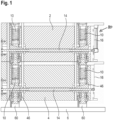
Figure 1 is a horizontal cross-section through two devices connected to each other with locking cartridges, -
Figure 2 shows at an enlarged scale the combination of two of the locking cartridges fromFigure 1 , -
Figure 3 shows at an even larger scale one of the cartridges shown inFigure 1 , -
Figure 4 shows in a perspective view a cartridge in a receiving position, -
Figure 5 shows the cartridge ofFigure 4 in a clamping position; -
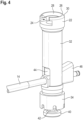
Figure 6 shows in a perspective view the screw-side portion of a rotating mechanism according to the invention, -
Figure 7 shows in a perspective exploded view the rotating mechanism according to the invention, -
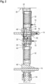
Figure 8 shows the rotating mechanism ofFigure 7 with the torque limiter in a longitudinal cross-section, -
Figure 9 shows at an enlarged scale portion IX ofFigure 8 , -
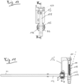
Figure 10 shows the rotating mechanism according to the invention in a lateral view, and -
Figure 11 shows the rotating mechanism in a longitudinal cross-section. - In
Figure 1 , afirst device 2 and asecond device 4 are shown, which are mounted on abase plate 6.Devices - Each of the
devices cartridges 10 which generally speaking serve for connectingadjacent devices base 6. - Locking
cartridges 10 can be operated by means of an actuating mechanism which comprises, apart from other elements discussed below, ascrew 14 which extends through therespective device cartridges 10 of therespective device front end 16 of therespective device - At
front end 16, a rotating mechanism is provided which is for rotatingscrew 14 and which will be described later with reference toFigure 6 to 11 . The rotating mechanism is depicted schematically inFigure 1 for the one ofscrews 14 and is designated withreference numeral 80. - Each of locking
cartridges 10 comprises a "passive" end and an "active" end. The active end is intended to grasp and clamp the passive end of anadjacent locking cartridge 10 or a suitable element provided atbase 6. - The passive end of each locking
cartridge 10 is an anchoringend 20 which comprises ananchor 22.Anchor 22 has a laterally open receiving channel 24 (please see alsoFigures 4 and5 ) which at the distal end is limited by a ring-shaped centeringprojection 26. Centeringprojection 26 is in the form of a convex centering projection which has obliquely extending inner and outer centeringsurfaces -
Anchor 22 is rigidly connected to ahousing 32 of lockingcartridge 10. In the shown embodiment,housing 32 andanchor 22 are formed in one piece. - The active end of the locking cartridges is a clamping end adapted to clamp the
anchor 22 of anadjacent locking cartridge 10. The clamping end is provided with astationary abutment element 34 and adisplaceable clamping element 36. -
Stationary abutment element 34 is here generally ring-shaped and connected tohousing 32. In this particular embodiment,abutment element 34 is threaded onto a thread provided at the end ofhousing 32 which is opposite to anchor 22. - At its distal end,
abutment element 34 has a circumferentially extending centeringgroove 38, with the inclination of the two lateral surfaces corresponding to the inclination ofsurfaces anchor 22. - Clamping
element 36 is arranged centrally withinabutment element 34 and comprises at its distal end ahead portion 40 which is connected via aneck portion 42 tobody 44 of clampingelement 36. - The diameter of
head portion 40 corresponds approximately to the inner dimension of receivingchannel 24 and the diameter ofneck portion 42 is slightly less than the smallest diameter of centeringprojection 26. - In this particular embodiment, clamping
element 36 is formed in two parts, with the part comprisinghead portion 40 being threaded intobody 44. - Clamping
element 36 is displaceably received withinhousing 32 so that it can move in a translational manner in the direction of arrow A with respect tohousing 32. - A
wedge 46 is provided which is part of the actuating mechanism and which extends through a recess in clamping element 36 (more specifically: through a recess in body 44) and a window inhousing 32.Wedge 46 cooperates with clampingelement 36 by engaging at asurface 48 which limits the recess at the side opposite tohead portion 40, and anedge 50 which limits the window at the side towardshead portion 40.Wedge 46 can be driven in the direction of arrow B with respect tohousing 32 of therespective cartridge 10 by means ofscrew 14. To this end, screw 14 is provided with anexternal thread 52 which cooperates with aninternal thread 54 provided withinwedge 46. - As can be seen in
Figure 1 , each of thescrews 14 cooperates with twocartridges 10, with thewedges 46 of the cartridges being oriented in opposite directions. Furthermore, the direction ofthreads wedges 46 cooperating with one and thesame screw 14 are opposite to each other. As a result, turningscrew 14 in one direction results in thewedges 46 cooperating with thisscrew 14 being drawn towards each other, androtating screw 14 in the opposite direction results in thewedges 46 being spaced from each other. - In an alternative embodiment (not shown), the thread on the screw is provided only at one end while the screw is rotatably connected to the respective wedge at the other end via an abutment. The wedge not provided with a thread is therefore moved by reaction forces.
- A
spring 56 is arranged withinhousing 32, withspring 56 piercing clampingelement 36 away from a clamping position in a position in whichhead portion 40 protrudes fromabutment element 34. - In a starting position, wedge 46 only slightly engages into the recess in clamping
element 36 and the window inhousing 32. In this position,head portion 40 protrudes from abutment element 34 (please see the condition shown inFigure 4 ). - This position of
head portion 40 allows to either engage into the receivingchannel 24 of ananchor 22 of a device arranged underneath or at an anchoringelement 60 provided atbase 6. - Assuming that
device 4 is to be mounted onbase 6,head portion 40 is engaged into a groove of anchoringelements 60 which are connected tobase 6. Subsequently, screw 14 is rotated so as to drawwedges 46 towards each other, thereby drawinghead portions 40 upwardly so as to clamp theanchoring elements 60 againstabutment elements 34 ofcartridges 10. As a result,device 4 is rigidly connected tobase 6. - In a subsequent step,
device 2 is placed ondevice 4, withcartridges 10 being in a mounting position (please seeFigure 4 ) in whichhead portion 40 protrudes from the respective cartridge. After engaginghead portions 40 into receivingchannel 24 ofanchors 22 arranged on the opposite ofdevice 4, screw 14 ofdevice 2 is rotated in a clamping direction so as to drawwedges 46 towards each other, thereby drawinghead portion 40 into the clamping position (please seeFigure 5 ) in which centeringprojection 26 is centered withinabutment element 34 anddevice 2 is reliably connected todevice 4. - For disengaging
devices base 6, screws 14 are rotated in the opposite direction (referred to here as being the disassembling direction) such thathead portions 40 are displaced from the clamping position into the mounting position in which they protrude from therespective cartridge 10. Then,head portion 40 can be disengaged from receivingchannel 24 of the anchor arranged underneath. - The forces occurring during actuation of the respective cartridge are shown in
Figure 2 . - The force exerted by
screw 14 ontowedge 46 is shown witharrow 70. This force is counteracted byforces 72 resulting fromhousing 32 of therespective locking cartridge 10 andabutment sleeve 34 which are both received within therespective device wedge 46 cooperating with clampingelement 34 and clampingelement 34 cooperating withanchor 22 is shown with a thinclosed line 74. - One advantage of the described embodiment is that a comparatively low actuating force of
screw 14 results in high clamping forces as there is a first amplification viathreads wedges 46. - It is generally possible to use an actuating mechanism which directly provides the axial displacement of
head portion 40 instead of using a mechanism which extends perpendicularly with respect to the central access of the respective locking cartridges. - Another advantage of the cartridges is that they provide for a positioning and fixing at the same time so that a compact design is achieved.
- It is also advantageous that two cartridges can be actuated with one
screw 14. - The locking cartridges generate the axial clamping force without placing an axial load on adjacent components. It is here only the lateral force between two simultaneously actuated cartridges which has to be counteracted by the respective device.
- The combination of
threads wedges 46 generated a locking mechanism which is self-locking because of the friction involved in the cooperating surfaces. - Due to the short force flow and the resulting high rigidity, the required pretensioning force is very low.
- Any manufacturing tolerances are simply compensated for by the preload. Only a few dimensions have to be manufactured with a small tolerance field, which enables manufacturing costs to be optimized.
- The contacting cone surfaces of the cartridge and cone nut can be produced by turning, which simply allows high precision at low cost.
- The fit of the cartridge can be produced by machining from a clamping direction on the processing machine. This results in inherent high possible accuracy for all three directions of the Cartesian coordinate system.
- Unlocking can be accomplished by spring force assistance, which favors easy separation of the two objects.
- Depending on the nature of the object, parts of the locking mechanism can be integrated to reduce the variety of parts.
- If this principle is designed as a cartridge or insert part, a damaged part, if any, can be replaced.
- Recycling is simplified by the use of a harmonized alloy and easily separable connections.
- With reference to
Figures 6 to 11 , rotatingmechanism 80 used for rotatingscrews 14 in the clamping direction and the disassembling direction will now be described in detail. - Generally speaking, rotating
mechanism 80 is provided for allowing a user to rotatescrew 14 in the clamping direction when twodevices base 6, and to rotatescrew 14 in the disassembling direction when thedevices base 6. - Rotating
mechanism 80 is designed to allowing a user to apply the necessary torques to screw 14 without there being the need to have access to a tool. Further, rotatingmechanism 80 is designed to ensure that no excessive torque can be applied to screw 14 in the clamping direction while at the same time ensuring that the necessary torque for rotatingscrew 14 in the disassembling direction can be applied under all circumstances. For preventing that excessive torque is applied to screw 14, rotatingmechanism 80 includes a torque limiter. Further, an override mechanism is included inrotating mechanism 80 so that it is ensured that the torque limiter does not limit the torque which can be applied to screw 14 in the disassembling direction. - The torque limiter and the override mechanism are formed from two
toothed elements spring 86.Toothed elements - One of
toothed elements toothed disk 82 which is mounted non-rotatable to screw 14 atfront end 16.Toothed disk 82 is provided with an axially orientedtoothing 83. - For mounting
toothed disk 82 to screw 14, abolt 88 is provided which extends through abore 90 in screw 14 (please see in particularFigure 9 ).Bolt 88 is received in a pocket on a "rear side" oftoothed disk 82 which is the side facing away from the toothing ofdisk 82. The width of the pocket on the rear side oftoothed disk 82 is slightly larger than the diameter ofbolt 88 so that the disk is held non-rotatably. - The other one of
toothed elements housing 84 which is generally cup-shaped with aperipheral wall 92. On an annular front face of drivingperipheral wall 92, an axially orientedtoothing 94 is provided. - Within driving
housing 84, biasingspring 86 is received. Biasingspring 86 is here formed from a plurality of individual disk springs ("Belleville springs") 96. The spring package formed from disk springs 96 is mounted within drivinghousing 84 by means of acirclip 98 which engages into an annular groove formed in the interior surface of drivinghousing 84adjacent toothing 94. The other end of the spring package formed from disk springs 96 abuts at aflange 102 formed on a nut 104 which is threaded onto the free end ofscrew 14. By tightening nut 104, biasingspring 86 is compressed and biases toothing 94 of drivinghousing 84 againsttoothing 83 ofdisk 82. Drivinghousing 84 is provided with anaxially extending hole 105 which provided access to nut 104 so as to allow tightening of the nut, e.g. by inserting an Allen wrench. - Nut 104 is here tightened until it
contacts disk 82. This mechanically defines the position of nut 104. In an alternative, the compression of biasingspring 86 can be variable by tightening nut 104 until an individual pretension is achieved. Nut 104 is then locked in its position. -
Toothings - Here, one of the flanks (here designated with "A") is arranged in a plane which extends through the central axis of
screw 14. In other words, a line which is perpendicular to the flanks A extends in a plane which is perpendicular to the central axis ofscrew 14. - The other flank (here designated with "B") is arranged with a slight inclination with respect to a plane which is perpendicular to the central axis of
screw 14. - The different orientations of the flanks A, B of
toothings toothing 94 is pressed againsttoothing 83 forms a torque limiter having two different levels depending on the direction of torque transmission. - When a torque is applied via driving
housing 84 in the clamping direction ofscrew 14, flanks B are used for torque transmission. The maximum torque which can be transmitted is defined by the pretensioning force exerted with biasingspring 86 and by the inclination of flanks A. The higher the pretensioning force and the steeper the orientation of the flanks, the higher the torque which can be transmitted before drivinghousing 84 is axially displaced against the force of biasingspring 86 andtoothing 94 slips with respect totoothing 83. In this condition, no further torque can be transmitted. - When a torque is applied via driving
housing 84 in the disassembling direction ofscrews 14, flanks A are used for torque transmission. Because of the orientation of the flanks A, the force transmitted via flanks A does not have an axial component so there is no tendency for drivinghousing 84 to be axially displaced with respect todisk 82. Thus, the orientation of the flanks A acts as an override mechanism for the torque limiter, and there is no limitation of the transmittable torque. - On its side facing away from
toothing 94, drivinghousing 84 is provided with two holdinglugs 106 between which ahandle 108 is mounted. - Handle 108 is an elongated tube with an
oblong hole 110 through which a mountingbolt 112 extends. Mountingbolt 112 is received in two openings 114 provided adjacent the free ends of holdinglugs 108 and axially fixed therein by means of two small fixation pins 116. - Handle 108 is displaceable along its longitudinal axis because of
oblong hole 110 allowing for a displacement ofhandle 108 with respect to mountingbolt 112. InFigure 8 , handle 108 is shown in a "short" position which is referred to as being a rest position. From this position, handle 108 can be displaced (with respect toFigure 8 ) upwardly so that the effective length of handle 108 (the distance between mountingbolt 112 and the free end having the larger distance from mounting bolt 112) is larger than in the rest position. The displaced position is referred to as being an actuating position. - An
extension spring 118 is arranged withinhandle 108. It abuts with one end in the interior ofhandle 108 and with its other end at mountingbolt 112. Accordingly, handle 108 is biased into the actuating position. - A
storing mechanism 120 is provided which fixes handle 108 in the rest position and in a defined, non-rotatable position. In the shown embodiment,storing mechanism 120 fixes handle 108 in a vertical position. -
Storing mechanism 120 can be a pair of spring arms or any other connection which allows to reliably fixhandle 108 in the desired position. - For mounting the devices to each other or for disassembling them, handle 108 is brought to the actuating position. In order to not interfere with
storing mechanism 120, handle 108 is slightly tilted with its longer end outwardly as schematically indicated with the dashed line inFigure 11 . Then, screw 14 can be rotated. - When the
devices handle 108 does not result in motion ofscrew 14. Handle 108 can nevertheless be continued to be turned until it is in a position (here vertical) in which it can be transferred from the actuating position into the rest position and fixed instoring mechanism 120. Because of the fixation ofhandle 108 in storingmechanism 120, unintentional rotation ofscrew 14 in the disassembling direction is reliably prevented.
Claims (15)
- A locking mechanism for mounting devices (2, 4) to each other, the locking mechanism having a plurality of locking cartridges (10) receivable in the devices (2, 4), the locking cartridges having a clamping system, the clamping system having a screw (14) and a rotating mechanism (80) for rotating the screw (14) in a clamping direction and a disassembling direction, the rotating mechanism (80) including a torque limiter (82, 84, 86) for limiting a torque applied to the screw (14) in the clamping direction.
- The locking mechanism of claim 1 wherein the rotating mechanism (80) includes an override mechanism for applying a torque onto the screw (14) in the disassembling direction which is higher than the torque transmitted by the torque limiter in the clamping direction.
- The locking mechanism of claim 1 or claim 2 wherein the torque limiter includes a biasing spring (86) for creasing a pretension.
- The locking mechanism of any one of the preceding claims wherein the torque limiter includes at least one toothed element (82, 84) with asymmetrical teeth.
- The locking mechanism of any one of the preceding claims wherein the torque limiter includes a toothed disk (82) which is mounted non-rotationally to the screw (14), and a driving housing (84) which has a toothing cooperating (94) with the toothed disk.
- The locking mechanism of claim 5 wherein the toothed disk (82) is held non-rotatably on the screw (14) by means of a bolt (88) extending through the screw (14) and being received in a pocket on the side of the disk (82) which faces away from the teeth (83) of the disk (82).
- The locking mechanism of claim 5 or claim 6 wherein one flank of the teeth is arranged in a plane which extends through the central axis of the screw (14), and the other flank of the teeth is arranged with a slight inclination with respect to a plane which is perpendicular to the central axis of the screw (14).
- The locking mechanism of any one of claims 5 to 7 wherein a spring package (96) is arranged within the driving housing (84).
- The locking mechanism of claim 8 wherein the spring package (96) is supported with one end at the driving housing (84) and with the opposite end at a nut (104) which engages at the screw (14).
- The locking mechanism of claim 9 wherein the spring package (96) is supported at the driving housing (84) by means of a circlip (98) which engages into a groove formed within the driving housing (84).
- The locking mechanism of claim 9 of claim 10 wherein the nut (104) clamps the toothed disk (82) against the bolt (88).
- The locking mechanism of any one of the preceding claims wherein a handle (108) is provided which can assume a rest position and an actuating position.
- The locking mechanism of claim 12 wherein a storing mechanism (120) is provided in which the handle (108) can be placed when in the rest position.
- The locking mechanism of claim 12 or claim 13 wherein the effective length of the handle (108) in the actuating position is longer than in the rest position.
- The locking mechanism of claim 14 wherein an extension spring (118) is provided which biases the handle (108) into the actuating position.
Priority Applications (1)
| Application Number | Priority Date | Filing Date | Title |
|---|---|---|---|
| EP23208616.5A EP4553324A1 (en) | 2023-11-08 | 2023-11-08 | Locking mechanism for mounting devices to each other |
Applications Claiming Priority (1)
| Application Number | Priority Date | Filing Date | Title |
|---|---|---|---|
| EP23208616.5A EP4553324A1 (en) | 2023-11-08 | 2023-11-08 | Locking mechanism for mounting devices to each other |
Publications (1)
| Publication Number | Publication Date |
|---|---|
| EP4553324A1 true EP4553324A1 (en) | 2025-05-14 |
Family
ID=88745911
Family Applications (1)
| Application Number | Title | Priority Date | Filing Date |
|---|---|---|---|
| EP23208616.5A Pending EP4553324A1 (en) | 2023-11-08 | 2023-11-08 | Locking mechanism for mounting devices to each other |
Country Status (1)
| Country | Link |
|---|---|
| EP (1) | EP4553324A1 (en) |
Citations (2)
| Publication number | Priority date | Publication date | Assignee | Title |
|---|---|---|---|---|
| US4775260A (en) * | 1987-04-27 | 1988-10-04 | Rexnord Inc. | Printed circuit board mounting apparatus |
| US20090252570A1 (en) * | 2008-03-10 | 2009-10-08 | Lee Robin C | Bench anchor |
-
2023
- 2023-11-08 EP EP23208616.5A patent/EP4553324A1/en active Pending
Patent Citations (2)
| Publication number | Priority date | Publication date | Assignee | Title |
|---|---|---|---|---|
| US4775260A (en) * | 1987-04-27 | 1988-10-04 | Rexnord Inc. | Printed circuit board mounting apparatus |
| US20090252570A1 (en) * | 2008-03-10 | 2009-10-08 | Lee Robin C | Bench anchor |
Similar Documents
| Publication | Publication Date | Title |
|---|---|---|
| US7125021B2 (en) | Self-locking drill chuck | |
| EP2420357B1 (en) | Torque wrench | |
| US20090255386A1 (en) | Torque Socket | |
| EP0761350A1 (en) | A locking device | |
| CN106984860A (en) | Miter saw | |
| JP2005103648A (en) | Rotating transfer device, and screwing device, caulking device and press-fitting device using rotating transfer device | |
| EP0734298A1 (en) | System for coupling machine tools | |
| US4456271A (en) | Tool holder with clamped position latch | |
| US12023784B2 (en) | Clamp locking mechanism | |
| JPS61188002A (en) | Tool holer | |
| US3625554A (en) | Device for rapid fixing of a tool to the end of a rotating shaft | |
| KR20030063081A (en) | Adjustable reaction arm for torque power tool, and torque power tool provided therewith | |
| WO2008092300A1 (en) | A locking drill chuck | |
| US7500661B2 (en) | Self-clamping mechanism | |
| US10286463B2 (en) | Bevel locking system | |
| TWI822256B (en) | Tool socket | |
| US11344954B2 (en) | Chuck with automatic jaw adjustment | |
| CN112388342B (en) | Anti-loose clamping chuck structure | |
| US20240308029A1 (en) | Clamp Locking Mechanism | |
| EP4478846A1 (en) | Locking cartridge and assembly comprising at least two devices to be connected to each other by means of such locking cartridges | |
| US8424879B2 (en) | Connection between two tool parts | |
| JP2007032611A (en) | Torque adjustment bolt | |
| CN116021050B (en) | Self-tightening drill chuck | |
| JP5035147B2 (en) | Automatic screw tightening jig | |
| TWI716315B (en) | Vise with soft jaw |
Legal Events
| Date | Code | Title | Description |
|---|---|---|---|
| PUAI | Public reference made under article 153(3) epc to a published international application that has entered the european phase |
Free format text: ORIGINAL CODE: 0009012 |
|
| STAA | Information on the status of an ep patent application or granted ep patent |
Free format text: STATUS: THE APPLICATION HAS BEEN PUBLISHED |
|
| AK | Designated contracting states |
Kind code of ref document: A1 Designated state(s): AL AT BE BG CH CY CZ DE DK EE ES FI FR GB GR HR HU IE IS IT LI LT LU LV MC ME MK MT NL NO PL PT RO RS SE SI SK SM TR |
|
| STAA | Information on the status of an ep patent application or granted ep patent |
Free format text: STATUS: REQUEST FOR EXAMINATION WAS MADE |
|
| 17P | Request for examination filed |
Effective date: 20251020 |
|
| GRAP | Despatch of communication of intention to grant a patent |
Free format text: ORIGINAL CODE: EPIDOSNIGR1 |
|
| STAA | Information on the status of an ep patent application or granted ep patent |
Free format text: STATUS: GRANT OF PATENT IS INTENDED |