EP4553320A1 - Refrigeration device - Google Patents
Refrigeration device Download PDFInfo
- Publication number
- EP4553320A1 EP4553320A1 EP24782425.3A EP24782425A EP4553320A1 EP 4553320 A1 EP4553320 A1 EP 4553320A1 EP 24782425 A EP24782425 A EP 24782425A EP 4553320 A1 EP4553320 A1 EP 4553320A1
- Authority
- EP
- European Patent Office
- Prior art keywords
- refrigerating machine
- machine oil
- refrigerant
- oil
- compressor
- Prior art date
- Legal status (The legal status is an assumption and is not a legal conclusion. Google has not performed a legal analysis and makes no representation as to the accuracy of the status listed.)
- Pending
Links
Images


Classifications
-
- F—MECHANICAL ENGINEERING; LIGHTING; HEATING; WEAPONS; BLASTING
- F25—REFRIGERATION OR COOLING; COMBINED HEATING AND REFRIGERATION SYSTEMS; HEAT PUMP SYSTEMS; MANUFACTURE OR STORAGE OF ICE; LIQUEFACTION SOLIDIFICATION OF GASES
- F25B—REFRIGERATION MACHINES, PLANTS OR SYSTEMS; COMBINED HEATING AND REFRIGERATION SYSTEMS; HEAT PUMP SYSTEMS
- F25B31/00—Compressor arrangements
- F25B31/002—Lubrication
-
- F—MECHANICAL ENGINEERING; LIGHTING; HEATING; WEAPONS; BLASTING
- F04—POSITIVE - DISPLACEMENT MACHINES FOR LIQUIDS; PUMPS FOR LIQUIDS OR ELASTIC FLUIDS
- F04B—POSITIVE-DISPLACEMENT MACHINES FOR LIQUIDS; PUMPS
- F04B39/00—Component parts, details, or accessories, of pumps or pumping systems specially adapted for elastic fluids, not otherwise provided for in, or of interest apart from, groups F04B25/00 - F04B37/00
- F04B39/02—Lubrication
- F04B39/0223—Lubrication characterised by the compressor type
- F04B39/023—Hermetic compressors
-
- F—MECHANICAL ENGINEERING; LIGHTING; HEATING; WEAPONS; BLASTING
- F04—POSITIVE - DISPLACEMENT MACHINES FOR LIQUIDS; PUMPS FOR LIQUIDS OR ELASTIC FLUIDS
- F04C—ROTARY-PISTON, OR OSCILLATING-PISTON, POSITIVE-DISPLACEMENT MACHINES FOR LIQUIDS; ROTARY-PISTON, OR OSCILLATING-PISTON, POSITIVE-DISPLACEMENT PUMPS
- F04C18/00—Rotary-piston pumps specially adapted for elastic fluids
- F04C18/02—Rotary-piston pumps specially adapted for elastic fluids of arcuate-engagement type, i.e. with circular translatory movement of co-operating members, each member having the same number of teeth or tooth-equivalents
- F04C18/0207—Rotary-piston pumps specially adapted for elastic fluids of arcuate-engagement type, i.e. with circular translatory movement of co-operating members, each member having the same number of teeth or tooth-equivalents both members having co-operating elements in spiral form
- F04C18/0215—Rotary-piston pumps specially adapted for elastic fluids of arcuate-engagement type, i.e. with circular translatory movement of co-operating members, each member having the same number of teeth or tooth-equivalents both members having co-operating elements in spiral form where only one member is moving
-
- F—MECHANICAL ENGINEERING; LIGHTING; HEATING; WEAPONS; BLASTING
- F04—POSITIVE - DISPLACEMENT MACHINES FOR LIQUIDS; PUMPS FOR LIQUIDS OR ELASTIC FLUIDS
- F04C—ROTARY-PISTON, OR OSCILLATING-PISTON, POSITIVE-DISPLACEMENT MACHINES FOR LIQUIDS; ROTARY-PISTON, OR OSCILLATING-PISTON, POSITIVE-DISPLACEMENT PUMPS
- F04C23/00—Combinations of two or more pumps, each being of rotary-piston or oscillating-piston type, specially adapted for elastic fluids; Pumping installations specially adapted for elastic fluids; Multi-stage pumps specially adapted for elastic fluids
- F04C23/008—Hermetic pumps
-
- F—MECHANICAL ENGINEERING; LIGHTING; HEATING; WEAPONS; BLASTING
- F04—POSITIVE - DISPLACEMENT MACHINES FOR LIQUIDS; PUMPS FOR LIQUIDS OR ELASTIC FLUIDS
- F04C—ROTARY-PISTON, OR OSCILLATING-PISTON, POSITIVE-DISPLACEMENT MACHINES FOR LIQUIDS; ROTARY-PISTON, OR OSCILLATING-PISTON, POSITIVE-DISPLACEMENT PUMPS
- F04C29/00—Component parts, details or accessories of pumps or pumping installations, not provided for in groups F04C18/00 - F04C28/00
- F04C29/02—Lubrication; Lubricant separation
-
- F—MECHANICAL ENGINEERING; LIGHTING; HEATING; WEAPONS; BLASTING
- F25—REFRIGERATION OR COOLING; COMBINED HEATING AND REFRIGERATION SYSTEMS; HEAT PUMP SYSTEMS; MANUFACTURE OR STORAGE OF ICE; LIQUEFACTION SOLIDIFICATION OF GASES
- F25B—REFRIGERATION MACHINES, PLANTS OR SYSTEMS; COMBINED HEATING AND REFRIGERATION SYSTEMS; HEAT PUMP SYSTEMS
- F25B13/00—Compression machines, plants or systems, with reversible cycle
-
- F—MECHANICAL ENGINEERING; LIGHTING; HEATING; WEAPONS; BLASTING
- F25—REFRIGERATION OR COOLING; COMBINED HEATING AND REFRIGERATION SYSTEMS; HEAT PUMP SYSTEMS; MANUFACTURE OR STORAGE OF ICE; LIQUEFACTION SOLIDIFICATION OF GASES
- F25B—REFRIGERATION MACHINES, PLANTS OR SYSTEMS; COMBINED HEATING AND REFRIGERATION SYSTEMS; HEAT PUMP SYSTEMS
- F25B31/00—Compressor arrangements
- F25B31/02—Compressor arrangements of motor-compressor units
- F25B31/026—Compressor arrangements of motor-compressor units with compressor of rotary type
-
- F—MECHANICAL ENGINEERING; LIGHTING; HEATING; WEAPONS; BLASTING
- F25—REFRIGERATION OR COOLING; COMBINED HEATING AND REFRIGERATION SYSTEMS; HEAT PUMP SYSTEMS; MANUFACTURE OR STORAGE OF ICE; LIQUEFACTION SOLIDIFICATION OF GASES
- F25B—REFRIGERATION MACHINES, PLANTS OR SYSTEMS; COMBINED HEATING AND REFRIGERATION SYSTEMS; HEAT PUMP SYSTEMS
- F25B2500/00—Problems to be solved
- F25B2500/16—Lubrication
Definitions
- the present disclosure relates to a refrigeration apparatus.
- the refrigeration apparatus described in Patent Document 1 includes an oil separator and an oil return passage for returning oil from the oil separator to a compressor.
- a sensor for detecting the concentration of a refrigerant in a lubricant in an oil reservoir is provided in the compressor, and the oil in the oil separator is returned to the compressor, based on the detected value by the sensor. This configuration adjusts the viscosity of the lubricant at the sliding portion in the compressor.
- Patent Document 1 Japanese Unexamined Patent Publication No. 2015-038406
- adjusting the viscosity of the refrigerating machine oil supplied to the sliding portion is important. Specifically, if the refrigerant is easily solvable in the refrigerating machine oil, a large amount of the refrigerant is dissolved in the refrigerating machine oil, which may result in a lower viscosity of the refrigerating machine oil supplied to the sliding portion. Selecting the refrigerant and the refrigerating machine oil, in which the refrigerant is dissolved appropriately, is thus important.
- a first aspect is directed to a refrigeration apparatus including a refrigerant circuit (101) and a compressor (115) in the refrigerant circuit (101), and configured to perform a refrigeration cycle.
- the compressor (115) includes a casing (11), an electric motor (21) in the casing (11), a drive shaft (23) extending in a longitudinal direction of the casing (11) and driven by the electric motor (21), and a compression mechanism (30) connected to the drive shaft (23), and an oil supply mechanism (29) configured to transport a refrigerating machine oil stored in an oil reservoir (17) at a bottom of the casing (11) to a predetermined sliding portion.
- the refrigerating machine oil contains a refrigerant and a refrigerating machine oil with a refrigerant solubility of 50 wt% or less.
- the refrigerant and the refrigerating machine oil in which the refrigerant solubility becomes 50 wt% or less, are selected. This reduces the dissolution of the refrigerant in the refrigerating machine oil and reduces a decrease in viscosity of the refrigerating machine oil containing the refrigerant dissolved therein. Accordingly, the refrigerating machine oil with less reduced viscosity is supplied to the sliding portion, and the lubricity in the sliding portion can thus be secured.
- a second aspect is an embodiment of the first aspect.
- the oil supply mechanism (29) is provided with a suction port (26a) which is in a lower portion of the oil reservoir (17) and sucks up the refrigerating machine oil.
- the refrigeration apparatus is configured to execute a first operation in which the refrigerating machine oil has a higher viscosity in a lower portion than in an upper portion of the oil reservoir (17).
- the refrigerant in which the refrigerant is relatively less soluble (with no refrigerant dissolved here), it takes time for the refrigerant to be dissolved uniformly in the refrigerating machine oil, resulting in a difference in the refrigerant solubility between the upper portion and the lower portion of the oil reservoir (17), which is obtained as a finding.
- the refrigerant solubility of the refrigerating machine oil in the lower portion is lower than in the upper portion.
- the oil reservoir (17) has a viscosity gradient in which the refrigerating machine oil has a higher viscosity in the lower portion than in the upper portion of the oil reservoir (17).
- the suction port (26a) is located in the lower portion of the oil reservoir (17), allowing the oil supply mechanism (29) to suck up the refrigerating machine oil with a relatively high viscosity. Accordingly, the lubricity can be ensured in the sliding portion.
- a third aspect is an embodiment of the first or second aspect.
- the refrigeration apparatus executes a first operation in which a circulation amount of the refrigerant flowing into the compressor (115) falls within a range from 0.3 kg/sec to 307 kg/sec inclusive, where an oil surface of the oil reservoir (17) has an area within a range from 141 mm 2 to 252 mm 2 inclusive.
- this operating condition can provide a viscosity gradient in which the refrigerating machine oil has a higher viscosity in the lower portion than in the upper portion of the oil reservoir (17).
- a fourth aspect is an embodiment of the second or third aspect.
- the refrigerating machine oil in the first operation, is whitened by bubbles generated in at least a portion of the oil reservoir (17).
- a minimum particle size of the bubbles is smaller than an inner diameter of the suction port (26a) which is in the oil supply mechanism (29) and sucks up the refrigerating machine oil in the oil reservoir (17).
- the refrigerator oil is whitened by the bubbles generated in part of the refrigerating machine oil in the oil reservoir (17).
- the refrigerating machine oil in the oil reservoir (17) has a viscosity gradient extending in the top-to-bottom direction.
- a fifth aspect is an embodiment of the second or third aspect.
- a refrigerant not dissolved in the refrigerating machine oil in the oil reservoir (17) is present.
- the part of the refrigerating machine oil is whitened by the refrigerant not dissolved in the refrigerating machine oil.
- a sixth aspect is an embodiment of any one of the first to fifth aspects.
- the refrigerating machine oil contains polyalkylene glycol (PAG).
- a seventh aspect is an embodiment of any one of the first to sixth aspects.
- the refrigerating machine oil contains polyalkylene glycol (PAG) having a hydroxyl group within a percent range from 40 mol% to 90 mol% inclusive with respect to all terminal groups.
- PAG polyalkylene glycol
- the slidability in the sliding portion of the compressor (115) can increase.
- An eighth aspect is an embodiment of any one of the first to seventh aspects.
- the refrigerant is hydrocarbon.
- the amount of refrigerant to be enclosed in the refrigerant circuit (101) can be reduced.
- An air conditioner (100) conditions air in an indoor space.
- the air conditioner (100) is an example of a refrigeration apparatus.
- the air conditioner (100) includes an outdoor unit (110), an indoor unit (120), a liquid connection pipe (102), and a gas connection pipe (103).
- the outdoor unit (110) and the indoor unit (120) are connected to each other via the liquid connection pipe (102) and the gas connection pipe (103). These components are connected together to form a refrigerant circuit (101).
- the refrigerant circuit (101) is filled with a refrigerant that performs a vapor compression refrigeration cycle. The refrigerant will be described in detail later.
- the refrigerant circuit (101) mainly includes a compressor (115), an outdoor heat exchanger (111), an expansion valve (113), an indoor heat exchanger (121), and a four-way switching valve (114).
- the outdoor unit (110) is placed outside.
- the outdoor unit (110) includes the compressor (115), the outdoor heat exchanger (111), the expansion valve (113), the four-way switching valve (114), and an outdoor fan (112).
- the compressor (115) sucks and compresses a low-pressure gas refrigerant.
- the compressor (115) discharges the compressed refrigerant.
- the compressor (115) is a variable capacity compressor in which power is supplied from an inverter circuit to an electric motor. In other words, the compressor (115) is capable of regulating the operation frequency (the number of rotations) of the electric motor.
- the outdoor heat exchanger (111) exchanges heat between outdoor air transported by the outdoor fan (112) and the refrigerant.
- the outdoor fan (112) transports outdoor air passing through the outdoor heat exchanger (111).
- the expansion valve (113) decompresses the refrigerant.
- the expansion valve (113) is an electric expansion valve having a variable opening degree.
- the four-way switching valve (114) has a first port (P1), a second port (P2), a third port (P3), and a fourth port (P4).
- the first port (P1) is connected to a discharge portion of the compressor (115).
- the second port (P2) is connected to a suction portion of the compressor (115).
- the third port (P3) is connected to a gas end of the outdoor heat exchanger (111).
- the fourth port (P4) is connected to the gas connection pipe (103).
- the four-way switching valve (114) switches between a first state (the state indicated by the solid curves in FIG. 1 ) and a second state (the state indicated by the broken curves in FIG. 1 ).
- the indoor unit (120) is placed inside.
- the indoor unit (120) mainly includes the indoor heat exchanger (121) and an indoor fan (122).
- the indoor heat exchanger (121) exchanges heat between indoor air transported by the indoor fan (122) and a refrigerant.
- the indoor fan (122) transports outdoor air passing through the outdoor heat exchanger (111).
- the refrigerant circuit (101) performs a first refrigeration cycle and a second refrigeration cycle according to switching of the four-way switching valve (114).
- the first refrigeration cycle is a refrigeration cycle in which the indoor heat exchanger (121) serves as an evaporator.
- the second refrigeration cycle is a refrigeration cycle in which the indoor heat exchanger (121) serves as a radiator.
- the air conditioner (100) includes a control unit (AC).
- the control unit (AC) controls the operation of the compressor (115).
- the control unit (AC) also controls the operations of various devices (e.g., the expansion valve (113), the indoor fan (122), and the outdoor fan (112)) of the air conditioner (100).
- the control unit (AC) is connected to various devices of the air conditioner (100) in a wired or wireless manner, and controls the operations of the various devices.
- the control unit (AC) includes a microcomputer and a memory device that stores software for operating the microcomputer.
- the compressor (115) of the present embodiment is a scroll compressor.
- the compressor (115) includes a casing (11), a rotary compression mechanism (30), and a drive mechanism (20) configured to rotatably drive the compression mechanism (30).
- the compression mechanism (30) and the drive mechanism (20) are housed in the casing (11).
- the casing (11) is configured as a vertically-long cylindrical closed container with both ends closed.
- the interior of the casing (11) is partitioned into upper and lower portions by an upper bearing housing (50) joined to the inner peripheral surface of the casing (11).
- a space above the upper bearing housing (50) constitutes an upper space (15), and a space below the upper bearing housing (50) constitutes a lower space (16).
- An oil reservoir (17) is provided at the bottom of the lower space (16) in the casing (11) to store refrigerating machine oil that lubricates the sliding portion of the compressor (115).
- the oil reservoir (17) is formed by accumulating the refrigerating machine oil in the compressor (115) at the bottom of the casing (11). That is, the amount of the refrigerating machine oil in the oil reservoir (17) varies depending on the environment in the casing (11), the operating state of the compressor, and other factors.
- the refrigerating machine oil in which part of the refrigerant enclosed in the refrigerant circuit (101) is dissolved or mixed in the refrigerating machine oil may be simply referred to as "refrigerating machine oil.”
- a suction pipe (18) and a discharge pipe (19) are attached to the casing (11).
- One end of the suction pipe (18) is connected to a suction pipe fitting (47).
- the discharge pipe (19) penetrates a barrel (12).
- An end of the discharge pipe (19) is open to the lower space (16) of the casing (11).
- the drive mechanism (20) includes a motor (21) and a crankshaft (drive shaft) (23).
- the motor (21) is housed in the lower space (16) of the casing (11).
- the motor (21) includes a stator (21a) and a rotor (21b), both of which are formed in a cylindrical shape.
- the stator (21a) is fixed to the inner peripheral surface of the casing (11).
- the rotor (21b) is disposed in a hollow portion of the stator (21a).
- the crankshaft (23) is fixed to pass through the rotor (21b) so that the rotor (21b) and the crankshaft (23) rotate together.
- the motor (21) is an example of an electric motor.
- the compression mechanism (30) is a so-called scroll compression mechanism, which includes a movable scroll (35), a fixed scroll (40), and the upper bearing housing (50).
- the upper bearing housing (50) and the fixed scroll (40) are fastened to each other using bolts (not shown).
- the movable scroll (35) is housed therebetween.
- the movable scroll (35) has a movable end plate (36) having a substantially disk shape.
- a movable wrap (37) stands on an upper surface of the movable end plate (36).
- the movable wrap (37) is a wall body extending radially outward from the vicinity of the center of the movable end plate (36) in a spiral manner. Further, a boss (38) protrudes from a lower surface of the movable end plate (36).
- the fixed scroll (40) has a fixed end plate (41) having a substantially disk shape.
- a fixed wrap (42) stands on a lower surface of the fixed end plate (41).
- the fixed wrap (42) is a wall body extending radially outward from the vicinity of the center of the fixed end plate (41) in a spiral manner, and meshing with the movable wrap (37) of the movable scroll (35).
- a compression chamber (31) is formed between the fixed wrap (42) and the movable wrap (37).
- the fixed scroll (40) has an outer edge (43) that extends continuously radially outward from the outermost peripheral wall of the fixed wrap (42). A lower end surface of this outer edge (43) is fixed to an upper end surface of the upper bearing housing (50).
- This outer edge (43) has an opening (44) open upward.
- This outer edge (43) also has a suction port (34) which communicates the inside of the opening (44) with the outermost end of the compression chamber (31).
- the suction port (34) is open at a suction point of the compression chamber (31).
- the suction pipe fitting (47) described above is connected to the opening (44) of this outer edge (43).
- the fixed end plate (41) of the fixed scroll (40) has a discharge port (32) located near the center of the fixed wrap (42) and passing therethrough in the top-to-bottom direction.
- the lower end of the discharge port (32) is open at the point where the fluid is discharged from the compression chamber (31).
- An upper end of the discharge port (32) opens to a discharge chamber (46) defined in an upper portion of the fixed scroll (40). Although not shown, this discharge chamber (46) communicates with the lower space (16) of the casing (11).
- the upper bearing housing (50) is formed in a substantially cylindrical shape.
- the outer peripheral surface of the upper bearing housing (50) has a larger diameter in an upper portion than in a lower portion.
- the upper portion of the outer peripheral surface is fixed to the inner peripheral surface of the casing (11).
- the upper bearing housing (50) is a member that divides the interior of the casing (11) in two spaces.
- the crankshaft (23) is inserted into the hollow portion of the upper bearing housing (50).
- the hollow portion of the upper bearing housing (50) is divided into a large-diameter portion and a small-diameter portion.
- the large-diameter portion is located above the small-diameter portion.
- a crank chamber (54), which will be described lager, is formed in the large-diameter portion.
- the small-diameter portion corresponds to an upper bearing portion (53).
- An upper bearing (62) is mounted on the upper bearing portion (53).
- the crank chamber (54) is a space defined by the large-diameter portion of the upper bearing housing (50) and the back surface of the movable scroll (35).
- the boss (38) of the movable scroll (35) is located in the crank chamber (54).
- a pin bearing (61) is fitted into the boss (38).
- the upper bearing housing (50) is provided with a seal member (55).
- the seal member (55) is sandwiched between the upper surface of the upper bearing housing (50) and the back surface of the movable scroll (35).
- the seal member (55) is provided on the upper surface of the upper bearing housing (50) so as to surround the large-diameter portion.
- the crank chamber (54) is separated from the space outside the crank chamber (54) by the seal member (55).
- a lower bearing housing (28) is provided near the lower end of the barrel (12) of the casing (11).
- a lower bearing (63) is mounted in the lower bearing housing (28).
- the crankshaft (23) includes a main shaft (24) and an eccentric portion (25).
- the main shaft (24) extends in the top-to-bottom direction.
- the eccentric portion (25) is provided at an upper end side of the main shaft (24).
- the eccentric portion (25) has a smaller diameter than the maximum diameter of the main shaft (24).
- the eccentric portion (25) has an axis decentered by a predetermined distance with respect to the axis of the main shaft (24).
- the eccentric portion (25) engages with the pin bearing (61) in the boss (38). As a result, the rotation of the crankshaft (23) causes an orbital motion of the movable scroll (35).
- crankshaft (23) is an example of a drive shaft.
- the compressor (115) has an oil supply mechanism (29) for supplying the refrigerating machine oil in the oil reservoir (17) to the sliding portion.
- the oil supply mechanism (29) includes an oil supply path (27) and an oil supply nozzle (26).
- the oil supply nozzle (26) extends in the axial direction inside the crankshaft (23).
- the oil supply path (27) branches toward the pin bearing (61), the upper bearing (62), and the lower bearing (63) in intermediate points while extending in the axial direction.
- the oil supply nozzle (26) is provided at the lower end of the crankshaft (23).
- the suction port (26a) of the oil supply nozzle (26) sucks up the refrigerating machine oil in the oil reservoir (17) of the casing (11). In terms of the height, the suction port (26a) is located below the oil reservoir (17).
- the expression “below the oil reservoir (17)” means below the midpoint between the bottom surface of the lower space (16) and the level of the refrigerating machine oil stored in the oil reservoir (17).
- the level of the refrigerating machine oil corresponds to the boundary between the refrigerating machine oil in the oil reservoir (17) of the casing (11) and the gas including the refrigerant gas.
- the level of the refrigerating machine oil varies depending on the environment in the casing (11), the operating state of the compressor (115), and other factors.
- the level of the refrigerating machine oil defined here may thus correspond to the highest oil level (i.e., the oil level at which the maximum amount of the refrigerating machine oil is stored in the casing (11)), the lowest oil level (i.e., the oil level at which the minimum amount of the refrigerating machine oil is stored in the casing (11)), or the oil level in the oil reservoir (17) at the start of operating the compressor (115).
- the level of the refrigerating machine oil defined above may correspond to the level of the upper end of the lower space (16).
- the height of the oil supply nozzle (26) falls within a range from 1 mm to 30 mm, preferably from 10 mm to 20 mm, from the bottom surface of the lower space (16).
- the outlet of the oil supply nozzle (26) is connected to the oil supply path (27) inside the crankshaft (23).
- the refrigerating machine oil sucked up from the oil reservoir (17) of the casing (11) by the oil supply nozzle (26) is supplied to sliding portions of the compressor (115), such as the pin bearing (61), the upper bearing (62), and the lower bearing (63).
- the refrigerating machine oil is mainly used to lubricate the sliding portions of the compressor (115).
- crank chamber (54) has the same pressure as the lower space (16) of the casing (11).
- the pressure of this crank chamber (54) acts on the back surface of the movable scroll (35), thereby pressing the movable scroll (35) onto the fixed scroll (40).
- control unit (AC) sets the four-way switching valve (114) in the first state.
- control unit (AC) operates the compressor (115), the outdoor fan (112), and the indoor fan (122), and adjusts the opening degree of the expansion valve (113).
- the refrigerant circuit (101) during the cooling operation performs a refrigeration cycle (cooling cycle) in which the outdoor heat exchanger (111) functions as a radiator and the indoor heat exchanger (121) functions as an evaporator.
- control unit (AC) sets the four-way switching valve (114) in the second state.
- control unit (AC) operates the compressor (115), the outdoor fan (112), and the indoor fan (122), and adjusts the opening degree of the expansion valve (113).
- the refrigerant circuit (101) during the heating operation performs a refrigeration cycle (heating cycle) in which the indoor heat exchanger (121) functions as a radiator and the outdoor heat exchanger (111) functions as an evaporator.
- the refrigerant of this embodiment is a hydrocarbon-based refrigerant.
- the hydrocarbon-based refrigerant is a refrigerant containing hydrocarbon (a hydrocarbon compound) as a main component.
- the carbon number of the hydrocarbon compound as a main component of the refrigerant preferably falls within a range from 1 to 8, more preferably from 1 to 5.
- Examples of the hydrocarbon compound as the main component of the refrigerant include methane, ethane, propane, n-butane, isobutane, n-pentane, isopentane, ethylene, and propylene.
- the refrigerant of this embodiment is R290.
- the refrigerating machine oil described here does not include a refrigerant.
- a refrigerating machine oil in which the refrigerant is relatively less soluble is selected.
- the refrigerating machine oil of this embodiment has a refrigerant solubility of 50 wt% or less.
- the refrigerant solubility may be 40 wt% or less or 30 wt% or less.
- the refrigerant solubility may be 37 wt%, where the condensation saturation temperature (Tc) of the refrigerant is 65°C and the temperature of the refrigerating machine oil is 67°C.
- a more specific example of the refrigerating machine oil may have a refrigerant solubility of 37 wt% in one preferred embodiment, where the condensation saturation temperature (Tc) of the refrigerant is 65°C and the temperature of the refrigerating machine oil is 67°C.
- the refrigerant solubility (wt%) represents the amount of the refrigerant dissolved in the refrigerating machine oil.
- the refrigerant solubility is expressed by the following equation.
- Refrigerant Solubility (wt%) Weight (wt) of Refrigerant in Refrigerating Machine Oil/Weight (wt) of Refrigerating Machine Oil Containing Refrigerant
- the weight of the refrigerating machine oil containing the refrigerant is the sum of the weight of the refrigerant and the weight of the refrigerating machine oil.
- the refrigerating machine oil contains polyalkylene glycol (PAG).
- PAG is a compound obtained by addition polymerization of an alkylene oxide.
- examples of the refrigerating machine oil include polyethylene glycol, polypropylene glycol, and a copolymer compound of polyethylene glycol and polypropylene glycol.
- the refrigerating machine oil may contain additives (e.g., an extreme pressure agent, an acid scavenger, and an antioxidant).
- the PAG has a hydroxyl group within a range from 40 mol% to 90 mol% inclusive with respect to all the terminal groups in one preferred embodiment.
- the PAG is polyethylene glycol (R1-[CH2CH2O]m-R2) (R1 is a hydrogen atom, a hydroxyl group (-OH), or a C1 to C8 hydrocarbon group or alkoxy group, and R2 is a hydrogen atom, a C1 to C8 hydrocarbon group or alkoxy group), the terminal groups are R1 and R2.
- the percentage of the hydroxyl group corresponds to the ratio of the number of R1 and R2 constituting the hydroxyl group to the total number of R1 and R4.
- R1 is a hydroxyl group, or R4 is a hydrogen atom
- the terminal group is a hydroxyl group.
- the refrigerating machine oil is composed of a composition A only, R1 contained in all molecules of the composition A is a hydrocarbon group, and R4 is a hydrogen atom, the terminal group containing R4 is a hydroxyl group at a hydroxyl group ratio of 50 mol%.
- the compressor (115) has a plurality of sliding portions where two members slide on each other.
- the sliding portions include the portion where the upper bearing portion (53) and the crankshaft (23) slide on each other, the portion where the lower bearing (63) and the crankshaft (23) slide on each other, and the portion where the pin bearing (61) and the crankshaft (23) slide on each other.
- the refrigerating machine oil transported from the oil reservoir (17) by the oil supply mechanism (29) is supplied to the sliding portions, thereby reducing the seizure and wear of the sliding portions
- the viscosity of the refrigerating machine oil containing the refrigerant varies depending on the solubility of the refrigerating machine oil, and if the viscosity is extremely high or low, the lubricity or slidability between the two members in each sliding portion may decrease.
- the refrigerating machine oil containing the refrigerant requires an appropriate viscosity.
- the viscosity and the solubility in the refrigerant differ depending on the type of the refrigerating machine oil.
- the viscosity of the refrigerating machine oil with the refrigerant dissolved or mixed in the refrigerating machine oil needs to be taken into consideration when selecting the refrigerating machine oil. For example, If in the refrigerating machine oil, the refrigerant is relatively less soluble, the viscosity becomes relatively high, and the shear resistance in the sliding portions also becomes high. There is thus a concern about a lower slidability in the sliding portions. In this manner, the refrigerating machine oil, in which the refrigerant is relatively less soluble, is not suitable for use as a lubricant for a compressor.
- the solubility in refrigerant can be obtained based on the temperature (i.e., the oil temperature) and the pressure of the refrigerating machine oil in the oil reservoir (17).
- the solubility in refrigerant may be higher (i.e., the viscosity is lower) than the theoretical value. It cannot be said that such a refrigerating machine oil has a sufficient lubricity in the sliding portions.
- this embodiment employs the refrigerating machine oil with a refrigerant solubility of 50 wt% or less and a higher viscosity in the lower portion than in the upper portion of the oil reservoir (17) in a predetermined operating state of the air conditioner (100). This reduces a decrease in lubricity in the sliding portions, which is obtained as a finding.
- a first operation as the predetermined operating state will be described.
- the refrigerating machine oil has a higher viscosity in a lower portion than in an upper portion of the oil reservoir (17).
- the circulation amount of the refrigerant flowing into the compressor (115) falls within a range from 0.3 kg/sec to 307 kg/sec inclusive, where an oil surface of the oil reservoir (17) has an area within a range from 141 mm 2 to 252 mm 2 inclusive.
- the circulation amount of the refrigerant flowing into the compressor (115) corresponds to the amount of the refrigerant compressed by the compressor (115) per unit time.
- the circulation amount of the refrigerant in the first operation falls within a range preferably from 0.5 kg/sec to 250 kg/sec inclusive, more preferably from 2.3 kg/sec to 200 kg/sec inclusive, furthermore preferably from 3.2 kg/sec to 136 kg/sec inclusive.
- the refrigerating machine oil is whitened by bubbles generated in at least part of the refrigerating machine oil in the oil reservoir (17).
- the minimum particle size of the bubbles is smaller than the inner diameter of the suction port (26a) of the oil supply nozzle (26).
- the inner diameter of the suction port (26a) of the oil supply nozzle (26) is larger than the minimum particle size of the bubbles generated in the refrigerating machine oil.
- This first operation is performed by the control unit (AC) controlling the frequency of the compressor (115), the opening degree of the expansion valve (113), and the other factors.
- the state where at least part of the refrigerating machine oil is whitened includes the state where part of the refrigerating machine oil becomes cloudy.
- the state where "at least part of the refrigerating machine oil is whitened” includes the state where the refrigerating machine oil changes to appear white.
- the state where "at least part of the refrigerating machine oil is whitened” includes the state where the refrigerating machine oil in the oil reservoir (17) changes from transparent to muddy white.
- the air conditioner (100) is brought into the operating state where the refrigerating machine oil has a higher viscosity in the lower portion than in the upper portion of the oil reservoir (17).
- the reason why the refrigerating machine oil has a higher viscosity in the lower portion than in the upper portion of the oil reservoir (17) is as follows. With an increase in the circulation amount of the refrigerant, the refrigerant dissolved in the refrigerating machine oil in the oil reservoir (17) is discharged from the refrigerating machine oil before uniformly dissolved in the refrigerating machine oil, and the concentration of the refrigerant becomes high in the upper portion and low in the lower portion of the oil reservoir (17), causing a gradient of the refrigerant solubility.
- the refrigerating machine oil has a higher viscosity in the lower portion than in the upper portion of the oil reservoir (17).
- the lower portion has a 10% or more higher viscosity than a reference value which is the viscosity of the upper portion of the oil reservoir (17) where the refrigerant has a pressure of 1.9 MPa and the refrigerating machine oil has a temperature of 70°C.
- the lower portion has an about 40% to about 60% higher viscosity than the reference value.
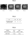
- FIG. 4 shows the state of the refrigerating machine oil in a steady state of the air conditioner (100).
- FIG. 4 is a photograph showing the state of the refrigerating machine oil in a liquid level gauge.
- the compressor (115) has a stable temperature and pressure and discharge overheating.
- Tc condensation saturation temperature
- Te 0°C
- SC 5K
- SH 8K
- the ratio of the actually measured value to the theoretical value of viscosity was evaluated. As the actually measured value of viscosity is closer to the theoretical value (i.e., as the ratio of the actually measured value to the theoretical value is closer to 1), the difference between the actually measured value and the theoretical value is smaller, and the reliability of the actual viscosity (actually measured value) is higher. As can be seen from FIG. 5 , when the number of rotations of the compressor (115) is 40 rps or more, the ratio of the actually measured value of viscosity to the theoretical value is less than 2, which indicates that the actual viscosity is not relatively high compared to the theoretical value.
- the amounts of wear in the sliding portions of the compressor (115) was measured at a sealed Falex wear test.
- the pins used at the Falex test was FC250 cast iron and the V-block material was A390 aluminum alloy.
- the pin and V-block material were set in a Falex tester as follows. After blowing a refrigerant into the V-block material immersed in the refrigerating machine oil, the V-block material was pressed against the pin and the pin was rotated, whereby the amounts of wear of the pin and the V-block material were measured.
- the test conditions are as shown in FIG. 6 . Specifically, the test conditions are as follows: the load was 667 N, the number of rotations was 290 rpm, the temperature of the refrigerating machine oil was 80°C, the test time was 60 minutes, and the amount of blowing the refrigerant was 10 liters/minute.
- the refrigerant and the refrigerating machine oil to be compared were R410A and FVC68D (manufactured by Idemitsu Kosan Co., Ltd.), respectively.
- the test was performed a plurality of times, and the amounts of wear of the pin and the V-block material were measured. As can be seen from FIG. 6 , the amount of wear was reduced in the refrigerating machine oil of the present embodiment as compared to those of the comparative object.
- a compressor (115) includes: a casing (11); an electric motor (21) in the casing (11); a drive shaft (23) extending in a longitudinal direction of the casing (11) and driven by the electric motor (21), a compression mechanism (30) connected to the drive shaft (23), and an oil supply mechanism (29) configured to transport a refrigerating machine oil stored in an oil reservoir (17) at a bottom of the casing (11) to a predetermined sliding portion.
- the refrigerating machine oil contains a refrigerant and refrigerating machine oil with a refrigerant solubility of 50 wt% or less.
- the refrigerant and the refrigerating machine oil are selected. This reduces the dissolution of the refrigerant in the refrigerating machine oil and reduces a decrease in the viscosity of the refrigerating machine oil containing the refrigerant dissolved herein. Accordingly, the refrigerating machine oil with less reduced viscosity is supplied to the sliding portion, and the lubricity in the sliding portion can thus be secured.
- the oil supply mechanism (29) is provided with a suction port (26a) which is in a lower portion of the oil reservoir (17) and sucks up the refrigerating machine oil.
- the air conditioner (100) executes a first operation in which the refrigerating machine oil has a higher viscosity in a lower portion than in an upper portion of the oil reservoir (17).
- the oil reservoir (17) has a viscosity gradient in which the refrigerating machine oil has a higher viscosity in the lower portion than in the upper portion of the oil reservoir (17).
- the suction port (26a) of the oil supply mechanism (29) is located in a lower portion of the oil reservoir (17). Accordingly, the oil supply mechanism (29) can suck up the refrigerating machine oil with a relatively high viscosity and ensure the lubricity at the sliding portions.
- a refrigerant has a higher specific gravity than refrigerating machine oil and is less soluble in the refrigerating machine oil, the refrigerant and the refrigerating machine oil are separated in the oil reservoir, and the refrigerant is accumulated in the lower portion of the oil reservoir.
- the suction port (26a) then sucks up more refrigerant than the refrigerating machine oil, resulting in poor lubrication at the sliding portions.
- the refrigerant does not have a higher specific gravity than the refrigerating machine oil, and the refrigerant and the refrigerating machine oil are less separated in the oil reservoir (17), which reduces poor lubrication at the sliding portions as described above.
- the air conditioner (100) of this embodiment executes a first operation in which a circulation amount of the refrigerant flowing into the compressor (115) falls within a range from 0.3 kg/sec to 307 kg/sec inclusive, where an oil surface of the oil reservoir (17) has an area within a range from 141 mm 2 to 252 mm 2 inclusive.
- the oil reservoir (17) can have a viscosity gradient in which the refrigerating machine oil has a higher viscosity in the lower portion than in the upper portion.
- the refrigerating machine oil is whitened by bubbles generated in at least a portion of the oil reservoir (17).
- the minimum particle size of the bubbles is smaller than the inner diameter of the suction port (26a).
- the oil reservoir (17) can have a viscosity gradient of the refrigerating machine oil with an increasing viscosity from the upper portion to the lower portion.
- the refrigerating machine oil according to this embodiment contains polyalkylene glycol (PAG). Accordingly, the refrigerating machine oil with a relatively low refrigerant solubility can be obtained.
- PAG polyalkylene glycol
- the refrigerating machine oil according to this embodiment contains polyalkylene glycol (PAG) having a hydroxyl group within a range from 40 mol% to 90 mol% inclusive with respect to all terminal groups.
- PAG polyalkylene glycol
- the hydroxyl group ratio in the refrigerating machine oil is within the range of 40 mol% or less, the amount of wear is large, and with an increase in the hydroxyl group ratio in the refrigerating machine oil up to 40 mol%, the amount of wear decreases, which is obtained as a finding.
- the hydroxyl group ratio in the refrigerating machine oil is preferably 40 mol% or more. It has been confirmed that when the hydroxyl group ratio in the refrigerating machine oil exceeds 90 mol%, the concentration of the refrigerating machine oil in the oil reservoir (17) becomes high, and the refrigerating machine oil is less likely to return to the compressor.
- the hydroxyl group ratio in the refrigerating machine oil is preferably 90 mol% or less.
- the refrigerant of this embodiment is a hydrocarbon. Since the refrigerating machine oil has a relatively low solubility, the amount of refrigerant to be enclosed in the refrigerant circuit (101) can be reduced.
- the above embodiment may also be configured as follows.
- a refrigerant not dissolved in the refrigerating machine oil in the oil reservoir (17) may be present in the first operation.
- a refrigerant not dissolved in the refrigerating machine oil but mixed in the refrigerating machine oil is present in the oil reservoir (17), part of the refrigerating machine oil is whitened by the first operation.
- the refrigerating machine oil has a viscosity gradient with an increasing viscosity from the upper portion to the lower portion.
- the hydrocarbon-based refrigerant may be a refrigerant composed of a hydrocarbon compound only, or may be a mixture of a hydrocarbon compound and a refrigerant other than a hydrocarbon compound.
- the refrigerant other than a hydrocarbon compound include a fluorine-containing refrigerant, such as R-134a, and carbon dioxide. If the hydrocarbon-based refrigerant includes a refrigerant other than a hydrocarbon compound, the content of the hydrocarbon compound is 50 wt% or more, 60 wt% or more, 70 wt% or more, 80 wt% or more, or 90 wt% or more.
- the hydrocarbon-based refrigerant may contain only one kind of hydrocarbon compound or two or more kinds of hydrocarbon compounds.
- the refrigerating machine oil may be a refrigerant composed of PAG only, or may be a mixture of PAG and a lubricant other than PAG.
- a lubricant other than PAG include mineral oil and alkylbenzene. If the refrigerating machine oil contains a lubricant other than PAG, the content of the PAG is 50 wt% or more, 60 wt% or more, 70 wt% or more, 80 wt% or more, or 90 wt% or more.
- the refrigerating machine oil may contain only one kind of PAG or two or more kinds of PAGs.
- the terminal groups are R3 and R4 included in the chemical formula of polypropylene glycol and a methyl group included in the repeat unit [CH(CH3)CH2O]n.
- the hydroxyl group ratio corresponds to the ratio of the number of R3 and R4 constituting the methyl group to the total number of R3 and R4. If R3 is a hydroxyl group or where R4 is a hydrogen atom, the terminal group is a hydroxyl group.
- the refrigerating machine oil is the copolymer of polypropylene glycol and polypropylene glycol (R5-[CH2CH2O]m-[CH(CH3)CH2O]n-R6)
- the terminal groups are R5 and R6 included in the chemical formula of the copolymer and a methyl group included in the repeat unit [CH(CH3)CH2O]p.
- the hydroxyl group ratio corresponds to the ratio of the number of R5 and R6 constituting the hydroxyl group to the total number of R5, R6, and the methyl group. If R5 is a hydroxyl group or where R6 is a hydrogen atom, the terminal group is a hydroxyl group.
- R3 and R5 may be a hydrogen atom, a hydroxyl group (-OH) or a C1 to C8 hydrocarbon group or alkoxy group.
- R4 and R6 may be a hydrogen atom or a C1 to C8 hydrocarbon group or alkoxy group.
- the compressor of the embodiment described above may be a rotary compressor or a scroll compressor.
- the number of rotations of the compressor (115) may be 11 rps or more. At this time, part of the refrigerating machine oil in the oil reservoir (17) is whitened. In the first operation, the number of rotations of the compressor (115) may be 15 rps or more, 30 rps or more, 50 rps or more, or 70 rps or more.
- the bubbles in the oil reservoir (17) are generated in the first operation by a liquid refrigerant or a gas refrigerant present in the refrigerating machine oil.
- the present disclosure is useful for a refrigeration apparatus.
Landscapes
- Engineering & Computer Science (AREA)
- Mechanical Engineering (AREA)
- General Engineering & Computer Science (AREA)
- Physics & Mathematics (AREA)
- Thermal Sciences (AREA)
- Applications Or Details Of Rotary Compressors (AREA)
- Compressor (AREA)
Abstract
Description
- The present disclosure relates to a refrigeration apparatus.
- The refrigeration apparatus described in Patent Document 1 includes an oil separator and an oil return passage for returning oil from the oil separator to a compressor. A sensor for detecting the concentration of a refrigerant in a lubricant in an oil reservoir is provided in the compressor, and the oil in the oil separator is returned to the compressor, based on the detected value by the sensor. This configuration adjusts the viscosity of the lubricant at the sliding portion in the compressor.
- Patent Document 1:
Japanese Unexamined Patent Publication No. 2015-038406 - In this manner, in order to satisfy the reliability, such as higher slidability and less wear in the sliding portion in the compressor, adjusting the viscosity of the refrigerating machine oil supplied to the sliding portion is important. Specifically, if the refrigerant is easily solvable in the refrigerating machine oil, a large amount of the refrigerant is dissolved in the refrigerating machine oil, which may result in a lower viscosity of the refrigerating machine oil supplied to the sliding portion. Selecting the refrigerant and the refrigerating machine oil, in which the refrigerant is dissolved appropriately, is thus important.
- In is an object of the present disclosure to ensure lubricity at a sliding portion in a compressor, even with refrigerating machine oil in which a refrigerant is relatively less soluble.
- A first aspect is directed to a refrigeration apparatus including a refrigerant circuit (101) and a compressor (115) in the refrigerant circuit (101), and configured to perform a refrigeration cycle. The compressor (115) includes a casing (11), an electric motor (21) in the casing (11), a drive shaft (23) extending in a longitudinal direction of the casing (11) and driven by the electric motor (21), and a compression mechanism (30) connected to the drive shaft (23), and an oil supply mechanism (29) configured to transport a refrigerating machine oil stored in an oil reservoir (17) at a bottom of the casing (11) to a predetermined sliding portion. The refrigerating machine oil contains a refrigerant and a refrigerating machine oil with a refrigerant solubility of 50 wt% or less.
- In the first aspect, in the combination of the refrigerant and the refrigerating machine oil (with no refrigerant dissolved here), the refrigerant and the refrigerating machine oil, in which the refrigerant solubility becomes 50 wt% or less, are selected. This reduces the dissolution of the refrigerant in the refrigerating machine oil and reduces a decrease in viscosity of the refrigerating machine oil containing the refrigerant dissolved therein. Accordingly, the refrigerating machine oil with less reduced viscosity is supplied to the sliding portion, and the lubricity in the sliding portion can thus be secured.
- A second aspect is an embodiment of the first aspect. In the second aspect, the oil supply mechanism (29) is provided with a suction port (26a) which is in a lower portion of the oil reservoir (17) and sucks up the refrigerating machine oil. The refrigeration apparatus is configured to execute a first operation in which the refrigerating machine oil has a higher viscosity in a lower portion than in an upper portion of the oil reservoir (17).
- In a combination of a refrigerant and refrigerating machine oil, in which the refrigerant is relatively less soluble (with no refrigerant dissolved here), it takes time for the refrigerant to be dissolved uniformly in the refrigerating machine oil, resulting in a difference in the refrigerant solubility between the upper portion and the lower portion of the oil reservoir (17), which is obtained as a finding. Specifically, in the oil reservoir (17), the refrigerant solubility of the refrigerating machine oil in the lower portion is lower than in the upper portion. In other words, the oil reservoir (17) has a viscosity gradient in which the refrigerating machine oil has a higher viscosity in the lower portion than in the upper portion of the oil reservoir (17). By contrast, in the second aspect, the suction port (26a) is located in the lower portion of the oil reservoir (17), allowing the oil supply mechanism (29) to suck up the refrigerating machine oil with a relatively high viscosity. Accordingly, the lubricity can be ensured in the sliding portion.
- A third aspect is an embodiment of the first or second aspect. In the third aspect, the refrigeration apparatus executes a first operation in which a circulation amount of the refrigerant flowing into the compressor (115) falls within a range from 0.3 kg/sec to 307 kg/sec inclusive, where an oil surface of the oil reservoir (17) has an area within a range from 141 mm2 to 252 mm2 inclusive. In the third aspect, this operating condition can provide a viscosity gradient in which the refrigerating machine oil has a higher viscosity in the lower portion than in the upper portion of the oil reservoir (17).
- A fourth aspect is an embodiment of the second or third aspect. In the fourth aspect, in the first operation, the refrigerating machine oil is whitened by bubbles generated in at least a portion of the oil reservoir (17). A minimum particle size of the bubbles is smaller than an inner diameter of the suction port (26a) which is in the oil supply mechanism (29) and sucks up the refrigerating machine oil in the oil reservoir (17).
- In the fourth aspect, the refrigerator oil is whitened by the bubbles generated in part of the refrigerating machine oil in the oil reservoir (17). In this state, the refrigerating machine oil in the oil reservoir (17) has a viscosity gradient extending in the top-to-bottom direction.
- A fifth aspect is an embodiment of the second or third aspect. In the fifth aspect, in the first operation, a refrigerant not dissolved in the refrigerating machine oil in the oil reservoir (17) is present.
- In the fifth aspect, the part of the refrigerating machine oil is whitened by the refrigerant not dissolved in the refrigerating machine oil.
- A sixth aspect is an embodiment of any one of the first to fifth aspects. In the sixth aspect, the refrigerating machine oil contains polyalkylene glycol (PAG).
- In the sixth aspect, with the use of polyalkylene glycol (PAG) as the refrigerating machine oil, refrigerating machine oil with a relatively low refrigerant solubility can be obtained.
- A seventh aspect is an embodiment of any one of the first to sixth aspects. In the seventh aspect,
the refrigerating machine oil contains polyalkylene glycol (PAG) having a hydroxyl group within a percent range from 40 mol% to 90 mol% inclusive with respect to all terminal groups. - In the seventh aspect, by selecting PAG having the hydroxyl group within such a percent range, the slidability in the sliding portion of the compressor (115) can increase.
- An eighth aspect is an embodiment of any one of the first to seventh aspects. In the eighth aspect,
the refrigerant is hydrocarbon. - In the eighth aspect, since the refrigerating machine oil has a relatively low solubility, the amount of refrigerant to be enclosed in the refrigerant circuit (101) can be reduced.
-
-
FIG. 1 is a piping system diagram of a refrigeration apparatus of an embodiment. -
FIG. 2 is a block diagram showing the relationship between a control unit and various devices. -
FIG. 3 is a longitudinal sectional view of a configuration of a compressor. -
FIG. 4 shows a result of studying the phenomenon of whitening refrigerating machine oil. -
FIG. 5 shows a result of studying the viscosity of the refrigerating machine oil. -
FIG. 6 shows a result of studying the wear resistance of the refrigerating machine oil. - Embodiments of the present invention will be described in detail below with reference to the drawings. The following embodiments are merely exemplary ones in nature, and are not intended to limit the scope, application, or uses of the invention. Features of the embodiments, variations, and other examples described below can be combined or partially substituted within the range where the present invention can be embodied.
- An air conditioner (100) conditions air in an indoor space. The air conditioner (100) is an example of a refrigeration apparatus. As shown in
FIG. 1 , the air conditioner (100) includes an outdoor unit (110), an indoor unit (120), a liquid connection pipe (102), and a gas connection pipe (103). The outdoor unit (110) and the indoor unit (120) are connected to each other via the liquid connection pipe (102) and the gas connection pipe (103). These components are connected together to form a refrigerant circuit (101). The refrigerant circuit (101) is filled with a refrigerant that performs a vapor compression refrigeration cycle. The refrigerant will be described in detail later. The refrigerant circuit (101) mainly includes a compressor (115), an outdoor heat exchanger (111), an expansion valve (113), an indoor heat exchanger (121), and a four-way switching valve (114). - The outdoor unit (110) is placed outside. The outdoor unit (110) includes the compressor (115), the outdoor heat exchanger (111), the expansion valve (113), the four-way switching valve (114), and an outdoor fan (112).
- The compressor (115) sucks and compresses a low-pressure gas refrigerant. The compressor (115) discharges the compressed refrigerant. The compressor (115) is a variable capacity compressor in which power is supplied from an inverter circuit to an electric motor. In other words, the compressor (115) is capable of regulating the operation frequency (the number of rotations) of the electric motor.
- The outdoor heat exchanger (111) exchanges heat between outdoor air transported by the outdoor fan (112) and the refrigerant. The outdoor fan (112) transports outdoor air passing through the outdoor heat exchanger (111).
- The expansion valve (113) decompresses the refrigerant. The expansion valve (113) is an electric expansion valve having a variable opening degree.
- The four-way switching valve (114) has a first port (P1), a second port (P2), a third port (P3), and a fourth port (P4). The first port (P1) is connected to a discharge portion of the compressor (115). The second port (P2) is connected to a suction portion of the compressor (115). The third port (P3) is connected to a gas end of the outdoor heat exchanger (111). The fourth port (P4) is connected to the gas connection pipe (103). The four-way switching valve (114) switches between a first state (the state indicated by the solid curves in
FIG. 1 ) and a second state (the state indicated by the broken curves inFIG. 1 ). - The indoor unit (120) is placed inside. The indoor unit (120) mainly includes the indoor heat exchanger (121) and an indoor fan (122).
- The indoor heat exchanger (121) exchanges heat between indoor air transported by the indoor fan (122) and a refrigerant. The indoor fan (122) transports outdoor air passing through the outdoor heat exchanger (111).
- The refrigerant circuit (101) performs a first refrigeration cycle and a second refrigeration cycle according to switching of the four-way switching valve (114). The first refrigeration cycle is a refrigeration cycle in which the indoor heat exchanger (121) serves as an evaporator. The second refrigeration cycle is a refrigeration cycle in which the indoor heat exchanger (121) serves as a radiator.
- As shown in
FIG. 2 , the air conditioner (100) includes a control unit (AC). The control unit (AC) controls the operation of the compressor (115). The control unit (AC) also controls the operations of various devices (e.g., the expansion valve (113), the indoor fan (122), and the outdoor fan (112)) of the air conditioner (100). The control unit (AC) is connected to various devices of the air conditioner (100) in a wired or wireless manner, and controls the operations of the various devices. The control unit (AC) includes a microcomputer and a memory device that stores software for operating the microcomputer. - The compressor (115) of the present embodiment is a scroll compressor. The compressor (115) includes a casing (11), a rotary compression mechanism (30), and a drive mechanism (20) configured to rotatably drive the compression mechanism (30). The compression mechanism (30) and the drive mechanism (20) are housed in the casing (11).
- The casing (11) is configured as a vertically-long cylindrical closed container with both ends closed. The interior of the casing (11) is partitioned into upper and lower portions by an upper bearing housing (50) joined to the inner peripheral surface of the casing (11). A space above the upper bearing housing (50) constitutes an upper space (15), and a space below the upper bearing housing (50) constitutes a lower space (16).
- An oil reservoir (17) is provided at the bottom of the lower space (16) in the casing (11) to store refrigerating machine oil that lubricates the sliding portion of the compressor (115). The oil reservoir (17) is formed by accumulating the refrigerating machine oil in the compressor (115) at the bottom of the casing (11). That is, the amount of the refrigerating machine oil in the oil reservoir (17) varies depending on the environment in the casing (11), the operating state of the compressor, and other factors. In the following description, the refrigerating machine oil in which part of the refrigerant enclosed in the refrigerant circuit (101) is dissolved or mixed in the refrigerating machine oil may be simply referred to as "refrigerating machine oil."
- A suction pipe (18) and a discharge pipe (19) are attached to the casing (11). One end of the suction pipe (18) is connected to a suction pipe fitting (47). The discharge pipe (19) penetrates a barrel (12). An end of the discharge pipe (19) is open to the lower space (16) of the casing (11).
- The drive mechanism (20) includes a motor (21) and a crankshaft (drive shaft) (23). The motor (21) is housed in the lower space (16) of the casing (11). The motor (21) includes a stator (21a) and a rotor (21b), both of which are formed in a cylindrical shape. The stator (21a) is fixed to the inner peripheral surface of the casing (11).
- The rotor (21b) is disposed in a hollow portion of the stator (21a). In the hollow portion of the rotor (21b), the crankshaft (23) is fixed to pass through the rotor (21b) so that the rotor (21b) and the crankshaft (23) rotate together. The motor (21) is an example of an electric motor.
- The compression mechanism (30) is a so-called scroll compression mechanism, which includes a movable scroll (35), a fixed scroll (40), and the upper bearing housing (50). The upper bearing housing (50) and the fixed scroll (40) are fastened to each other using bolts (not shown). The movable scroll (35) is housed therebetween.
- The movable scroll (35) has a movable end plate (36) having a substantially disk shape. A movable wrap (37) stands on an upper surface of the movable end plate (36). The movable wrap (37) is a wall body extending radially outward from the vicinity of the center of the movable end plate (36) in a spiral manner. Further, a boss (38) protrudes from a lower surface of the movable end plate (36).
- The fixed scroll (40) has a fixed end plate (41) having a substantially disk shape. A fixed wrap (42) stands on a lower surface of the fixed end plate (41). The fixed wrap (42) is a wall body extending radially outward from the vicinity of the center of the fixed end plate (41) in a spiral manner, and meshing with the movable wrap (37) of the movable scroll (35). A compression chamber (31) is formed between the fixed wrap (42) and the movable wrap (37).
- The fixed scroll (40) has an outer edge (43) that extends continuously radially outward from the outermost peripheral wall of the fixed wrap (42). A lower end surface of this outer edge (43) is fixed to an upper end surface of the upper bearing housing (50). This outer edge (43) has an opening (44) open upward. This outer edge (43) also has a suction port (34) which communicates the inside of the opening (44) with the outermost end of the compression chamber (31). The suction port (34) is open at a suction point of the compression chamber (31). The suction pipe fitting (47) described above is connected to the opening (44) of this outer edge (43).
- The fixed end plate (41) of the fixed scroll (40) has a discharge port (32) located near the center of the fixed wrap (42) and passing therethrough in the top-to-bottom direction. The lower end of the discharge port (32) is open at the point where the fluid is discharged from the compression chamber (31). An upper end of the discharge port (32) opens to a discharge chamber (46) defined in an upper portion of the fixed scroll (40). Although not shown, this discharge chamber (46) communicates with the lower space (16) of the casing (11).
- The upper bearing housing (50) is formed in a substantially cylindrical shape. The outer peripheral surface of the upper bearing housing (50) has a larger diameter in an upper portion than in a lower portion. The upper portion of the outer peripheral surface is fixed to the inner peripheral surface of the casing (11).
- The upper bearing housing (50) is a member that divides the interior of the casing (11) in two spaces. The crankshaft (23) is inserted into the hollow portion of the upper bearing housing (50). The hollow portion of the upper bearing housing (50) is divided into a large-diameter portion and a small-diameter portion. The large-diameter portion is located above the small-diameter portion. A crank chamber (54), which will be described lager, is formed in the large-diameter portion. The small-diameter portion corresponds to an upper bearing portion (53). An upper bearing (62) is mounted on the upper bearing portion (53).
- The crank chamber (54) is a space defined by the large-diameter portion of the upper bearing housing (50) and the back surface of the movable scroll (35). The boss (38) of the movable scroll (35) is located in the crank chamber (54). A pin bearing (61) is fitted into the boss (38).
- The upper bearing housing (50) is provided with a seal member (55). The seal member (55) is sandwiched between the upper surface of the upper bearing housing (50) and the back surface of the movable scroll (35). The seal member (55) is provided on the upper surface of the upper bearing housing (50) so as to surround the large-diameter portion. The crank chamber (54) is separated from the space outside the crank chamber (54) by the seal member (55).
- A lower bearing housing (28) is provided near the lower end of the barrel (12) of the casing (11). A lower bearing (63) is mounted in the lower bearing housing (28).
- The crankshaft (23) includes a main shaft (24) and an eccentric portion (25). The main shaft (24) extends in the top-to-bottom direction. The eccentric portion (25) is provided at an upper end side of the main shaft (24). The eccentric portion (25) has a smaller diameter than the maximum diameter of the main shaft (24). The eccentric portion (25) has an axis decentered by a predetermined distance with respect to the axis of the main shaft (24). The eccentric portion (25) engages with the pin bearing (61) in the boss (38). As a result, the rotation of the crankshaft (23) causes an orbital motion of the movable scroll (35). An upper end portion of the main shaft (24) of the crankshaft (23) is rotatably supported by the upper bearing (62) in the upper bearing portion (53) of the upper bearing housing (50). A lower end portion of the main shaft (24) is rotatably supported by the lower bearing (63) of the lower bearing housing (28). The crankshaft (23) is an example of a drive shaft.
- The compressor (115) has an oil supply mechanism (29) for supplying the refrigerating machine oil in the oil reservoir (17) to the sliding portion. The oil supply mechanism (29) includes an oil supply path (27) and an oil supply nozzle (26).
- The oil supply nozzle (26) extends in the axial direction inside the crankshaft (23). The oil supply path (27) branches toward the pin bearing (61), the upper bearing (62), and the lower bearing (63) in intermediate points while extending in the axial direction.
- The oil supply nozzle (26) is provided at the lower end of the crankshaft (23). The suction port (26a) of the oil supply nozzle (26) sucks up the refrigerating machine oil in the oil reservoir (17) of the casing (11). In terms of the height, the suction port (26a) is located below the oil reservoir (17). The expression "below the oil reservoir (17)" means below the midpoint between the bottom surface of the lower space (16) and the level of the refrigerating machine oil stored in the oil reservoir (17). The level of the refrigerating machine oil corresponds to the boundary between the refrigerating machine oil in the oil reservoir (17) of the casing (11) and the gas including the refrigerant gas. The level of the refrigerating machine oil varies depending on the environment in the casing (11), the operating state of the compressor (115), and other factors. The level of the refrigerating machine oil defined here may thus correspond to the highest oil level (i.e., the oil level at which the maximum amount of the refrigerating machine oil is stored in the casing (11)), the lowest oil level (i.e., the oil level at which the minimum amount of the refrigerating machine oil is stored in the casing (11)), or the oil level in the oil reservoir (17) at the start of operating the compressor (115). In addition, if the oil reservoir (17) is assumed to extend to the upper end of the lower space (16) at the maximum, the level of the refrigerating machine oil defined above may correspond to the level of the upper end of the lower space (16). Specifically, in this embodiment, the height of the oil supply nozzle (26) falls within a range from 1 mm to 30 mm, preferably from 10 mm to 20 mm, from the bottom surface of the lower space (16).
- The outlet of the oil supply nozzle (26) is connected to the oil supply path (27) inside the crankshaft (23). The refrigerating machine oil sucked up from the oil reservoir (17) of the casing (11) by the oil supply nozzle (26) is supplied to sliding portions of the compressor (115), such as the pin bearing (61), the upper bearing (62), and the lower bearing (63). The refrigerating machine oil is mainly used to lubricate the sliding portions of the compressor (115).
- The refrigerating machine oil supplied from the oil supply path (27) to the sliding surface between the pin bearing (61) and the eccentric portion (25) flows down into the crank chamber (54) by its own weight. Accordingly, this crank chamber (54) has the same pressure as the lower space (16) of the casing (11). The pressure of this crank chamber (54) acts on the back surface of the movable scroll (35), thereby pressing the movable scroll (35) onto the fixed scroll (40).
- In the cooling operation, the control unit (AC) sets the four-way switching valve (114) in the first state. In the cooling operation, the control unit (AC) operates the compressor (115), the outdoor fan (112), and the indoor fan (122), and adjusts the opening degree of the expansion valve (113).
- The refrigerant circuit (101) during the cooling operation performs a refrigeration cycle (cooling cycle) in which the outdoor heat exchanger (111) functions as a radiator and the indoor heat exchanger (121) functions as an evaporator.
- In the heating operation, the control unit (AC) sets the four-way switching valve (114) in the second state. In the heating operation, the control unit (AC) operates the compressor (115), the outdoor fan (112), and the indoor fan (122), and adjusts the opening degree of the expansion valve (113).
- The refrigerant circuit (101) during the heating operation performs a refrigeration cycle (heating cycle) in which the indoor heat exchanger (121) functions as a radiator and the outdoor heat exchanger (111) functions as an evaporator.
- The refrigerant of this embodiment is a hydrocarbon-based refrigerant. The hydrocarbon-based refrigerant is a refrigerant containing hydrocarbon (a hydrocarbon compound) as a main component. The carbon number of the hydrocarbon compound as a main component of the refrigerant preferably falls within a range from 1 to 8, more preferably from 1 to 5. Examples of the hydrocarbon compound as the main component of the refrigerant include methane, ethane, propane, n-butane, isobutane, n-pentane, isopentane, ethylene, and propylene. The refrigerant of this embodiment is R290.
- The refrigerating machine oil described here does not include a refrigerant. In this embodiment, a refrigerating machine oil in which the refrigerant is relatively less soluble is selected. The refrigerating machine oil of this embodiment has a refrigerant solubility of 50 wt% or less. The refrigerant solubility may be 40 wt% or less or 30 wt% or less. As an example condition, the refrigerant solubility may be 37 wt%, where the condensation saturation temperature (Tc) of the refrigerant is 65°C and the temperature of the refrigerating machine oil is 67°C. A more specific example of the refrigerating machine oil may have a refrigerant solubility of 37 wt% in one preferred embodiment, where the condensation saturation temperature (Tc) of the refrigerant is 65°C and the temperature of the refrigerating machine oil is 67°C. The refrigerant solubility (wt%) represents the amount of the refrigerant dissolved in the refrigerating machine oil. Specifically, the refrigerant solubility is expressed by the following equation.
Refrigerant Solubility (wt%) = Weight (wt) of Refrigerant in Refrigerating Machine Oil/Weight (wt) of Refrigerating Machine Oil Containing Refrigerant - The refrigerating machine oil contains polyalkylene glycol (PAG). PAG is a compound obtained by addition polymerization of an alkylene oxide. Examples of the refrigerating machine oil include polyethylene glycol, polypropylene glycol, and a copolymer compound of polyethylene glycol and polypropylene glycol. The refrigerating machine oil may contain additives (e.g., an extreme pressure agent, an acid scavenger, and an antioxidant).
- The PAG has a hydroxyl group within a range from 40 mol% to 90 mol% inclusive with respect to all the terminal groups in one preferred embodiment. For example, if the PAG is polyethylene glycol (R1-[CH2CH2O]m-R2) (R1 is a hydrogen atom, a hydroxyl group (-OH), or a C1 to C8 hydrocarbon group or alkoxy group, and R2 is a hydrogen atom, a C1 to C8 hydrocarbon group or alkoxy group), the terminal groups are R1 and R2. The percentage of the hydroxyl group corresponds to the ratio of the number of R1 and R2 constituting the hydroxyl group to the total number of R1 and R4. If R1 is a hydroxyl group, or R4 is a hydrogen atom, the terminal group is a hydroxyl group. For example, if the refrigerating machine oil is composed of a composition A only, R1 contained in all molecules of the composition A is a hydrocarbon group, and R4 is a hydrogen atom, the terminal group containing R4 is a hydroxyl group at a hydroxyl group ratio of 50 mol%.
- The compressor (115) has a plurality of sliding portions where two members slide on each other. Specifically, the sliding portions include the portion where the upper bearing portion (53) and the crankshaft (23) slide on each other, the portion where the lower bearing (63) and the crankshaft (23) slide on each other, and the portion where the pin bearing (61) and the crankshaft (23) slide on each other.
- The refrigerating machine oil transported from the oil reservoir (17) by the oil supply mechanism (29) is supplied to the sliding portions, thereby reducing the seizure and wear of the sliding portions However, the viscosity of the refrigerating machine oil containing the refrigerant varies depending on the solubility of the refrigerating machine oil, and if the viscosity is extremely high or low, the lubricity or slidability between the two members in each sliding portion may decrease. In order to increase the lubricity in the sliding portions, the refrigerating machine oil containing the refrigerant requires an appropriate viscosity.
- Here, the viscosity and the solubility in the refrigerant differ depending on the type of the refrigerating machine oil. The viscosity of the refrigerating machine oil with the refrigerant dissolved or mixed in the refrigerating machine oil needs to be taken into consideration when selecting the refrigerating machine oil. For example, If in the refrigerating machine oil, the refrigerant is relatively less soluble, the viscosity becomes relatively high, and the shear resistance in the sliding portions also becomes high. There is thus a concern about a lower slidability in the sliding portions. In this manner, the refrigerating machine oil, in which the refrigerant is relatively less soluble, is not suitable for use as a lubricant for a compressor. If in the refrigerating machine oil, the refrigerant is relatively soluble, the theoretical value of the solubility in refrigerant can be obtained based on the temperature (i.e., the oil temperature) and the pressure of the refrigerating machine oil in the oil reservoir (17). Depending on the operating conditions of the air conditioner, the solubility in refrigerant may be higher (i.e., the viscosity is lower) than the theoretical value. It cannot be said that such a refrigerating machine oil has a sufficient lubricity in the sliding portions.
- By contrast, this embodiment employs the refrigerating machine oil with a refrigerant solubility of 50 wt% or less and a higher viscosity in the lower portion than in the upper portion of the oil reservoir (17) in a predetermined operating state of the air conditioner (100). This reduces a decrease in lubricity in the sliding portions, which is obtained as a finding. Hereinafter, a first operation as the predetermined operating state will be described.
- In the first operation, the refrigerating machine oil has a higher viscosity in a lower portion than in an upper portion of the oil reservoir (17). In the first operation of this embodiment, the circulation amount of the refrigerant flowing into the compressor (115) falls within a range from 0.3 kg/sec to 307 kg/sec inclusive, where an oil surface of the oil reservoir (17) has an area within a range from 141 mm2 to 252 mm2 inclusive. At this time, the circulation amount of the refrigerant flowing into the compressor (115) corresponds to the amount of the refrigerant compressed by the compressor (115) per unit time. The circulation amount of the refrigerant in the first operation falls within a range preferably from 0.5 kg/sec to 250 kg/sec inclusive, more preferably from 2.3 kg/sec to 200 kg/sec inclusive, furthermore preferably from 3.2 kg/sec to 136 kg/sec inclusive.
- In the first operation, the refrigerating machine oil is whitened by bubbles generated in at least part of the refrigerating machine oil in the oil reservoir (17). The minimum particle size of the bubbles is smaller than the inner diameter of the suction port (26a) of the oil supply nozzle (26). In other words, the inner diameter of the suction port (26a) of the oil supply nozzle (26) is larger than the minimum particle size of the bubbles generated in the refrigerating machine oil. This first operation is performed by the control unit (AC) controlling the frequency of the compressor (115), the opening degree of the expansion valve (113), and the other factors.
- The state where at least part of the refrigerating machine oil is whitened includes the state where part of the refrigerating machine oil becomes cloudy. The state where "at least part of the refrigerating machine oil is whitened" includes the state where the refrigerating machine oil changes to appear white. The state where "at least part of the refrigerating machine oil is whitened" includes the state where the refrigerating machine oil in the oil reservoir (17) changes from transparent to muddy white.
- In the first operation, the air conditioner (100) is brought into the operating state where the refrigerating machine oil has a higher viscosity in the lower portion than in the upper portion of the oil reservoir (17). The reason why the refrigerating machine oil has a higher viscosity in the lower portion than in the upper portion of the oil reservoir (17) is as follows. With an increase in the circulation amount of the refrigerant, the refrigerant dissolved in the refrigerating machine oil in the oil reservoir (17) is discharged from the refrigerating machine oil before uniformly dissolved in the refrigerating machine oil, and the concentration of the refrigerant becomes high in the upper portion and low in the lower portion of the oil reservoir (17), causing a gradient of the refrigerant solubility. That is, the refrigerating machine oil has a higher viscosity in the lower portion than in the upper portion of the oil reservoir (17). For example, the lower portion has a 10% or more higher viscosity than a reference value which is the viscosity of the upper portion of the oil reservoir (17) where the refrigerant has a pressure of 1.9 MPa and the refrigerating machine oil has a temperature of 70°C. Specifically, in the first operation, the lower portion has an about 40% to about 60% higher viscosity than the reference value.
- The difference in change of the refrigerating machine oil depending on the number of rotations of the compressor (115) was studied. R290 was used as the refrigerant and SUNICEP-60M5 (manufactured by JAPAN SUN OIL COMPANY, LTD.) as the refrigerating machine oil. Although not shown, once the number of rotations of the compressor (115) reached 11 rps after the start of the operation of the air conditioner (100), cloudiness was found in part of the refrigerating machine oil.
-
FIG. 4 shows the state of the refrigerating machine oil in a steady state of the air conditioner (100).FIG. 4 is a photograph showing the state of the refrigerating machine oil in a liquid level gauge. In the steady state, the compressor (115) has a stable temperature and pressure and discharge overheating. Specifically, the condensation saturation temperature (Tc), the evaporation saturation temperature (Te), the subcooling degree (SC), and the superheating degree (SH) are Tc = 55°C, Te = 0°C, SC = 5K, and SH = 8K, respectively. As can be seen fromFIG. 4 , the refrigerating machine oil was whitened as a whole at 60 rps or more in the steady state. It was also found that the oil reservoir (17) had a viscosity gradient with an increasing viscosity from the upper portion to the lower portion at this time. - The difference in the viscosity of the refrigerating machine oil depending on the number of rotations of the compressor (115) was studied. The same refrigerant and refrigerating machine oil as those described above are used. The number of rotations, the theoretical value of viscosity, and the actually measured value of viscosity in the steady state (i.e., where Tc = 50°C, Te = 0°C, SC = 4K, and SH = 3K) were obtained. The theoretical values and the actually measured values of viscosity can be obtained by a known method.
- The ratio of the actually measured value to the theoretical value of viscosity was evaluated. As the actually measured value of viscosity is closer to the theoretical value (i.e., as the ratio of the actually measured value to the theoretical value is closer to 1), the difference between the actually measured value and the theoretical value is smaller, and the reliability of the actual viscosity (actually measured value) is higher. As can be seen from
FIG. 5 , when the number of rotations of the compressor (115) is 40 rps or more, the ratio of the actually measured value of viscosity to the theoretical value is less than 2, which indicates that the actual viscosity is not relatively high compared to the theoretical value. - The amounts of wear in the sliding portions of the compressor (115) was measured at a sealed Falex wear test. The pins used at the Falex test was FC250 cast iron and the V-block material was A390 aluminum alloy. The pin and V-block material were set in a Falex tester as follows. After blowing a refrigerant into the V-block material immersed in the refrigerating machine oil, the V-block material was pressed against the pin and the pin was rotated, whereby the amounts of wear of the pin and the V-block material were measured.
- The test conditions are as shown in
FIG. 6 . Specifically, the test conditions are as follows: the load was 667 N, the number of rotations was 290 rpm, the temperature of the refrigerating machine oil was 80°C, the test time was 60 minutes, and the amount of blowing the refrigerant was 10 liters/minute. The refrigerant and the refrigerating machine oil to be compared were R410A and FVC68D (manufactured by Idemitsu Kosan Co., Ltd.), respectively. The test was performed a plurality of times, and the amounts of wear of the pin and the V-block material were measured. As can be seen fromFIG. 6 , the amount of wear was reduced in the refrigerating machine oil of the present embodiment as compared to those of the comparative object. - In the air conditioner (100) of this embodiment, a compressor (115) includes: a casing (11); an electric motor (21) in the casing (11); a drive shaft (23) extending in a longitudinal direction of the casing (11) and driven by the electric motor (21), a compression mechanism (30) connected to the drive shaft (23), and an oil supply mechanism (29) configured to transport a refrigerating machine oil stored in an oil reservoir (17) at a bottom of the casing (11) to a predetermined sliding portion. The refrigerating machine oil contains a refrigerant and refrigerating machine oil with a refrigerant solubility of 50 wt% or less.
- Among combinations of refrigerants and refrigerating machine oils (with no refrigerants dissolved here), the refrigerant and the refrigerating machine oil, in which the refrigerant solubility becomes 50 wt% or less, are selected. This reduces the dissolution of the refrigerant in the refrigerating machine oil and reduces a decrease in the viscosity of the refrigerating machine oil containing the refrigerant dissolved herein. Accordingly, the refrigerating machine oil with less reduced viscosity is supplied to the sliding portion, and the lubricity in the sliding portion can thus be secured.
- In this embodiment, the oil supply mechanism (29) is provided with a suction port (26a) which is in a lower portion of the oil reservoir (17) and sucks up the refrigerating machine oil. The air conditioner (100) executes a first operation in which the refrigerating machine oil has a higher viscosity in a lower portion than in an upper portion of the oil reservoir (17).
- As described above, in the combination of the refrigerant and the refrigerating machine oil according to this embodiment, the oil reservoir (17) has a viscosity gradient in which the refrigerating machine oil has a higher viscosity in the lower portion than in the upper portion of the oil reservoir (17). Based on the finding, the suction port (26a) of the oil supply mechanism (29) is located in a lower portion of the oil reservoir (17). Accordingly, the oil supply mechanism (29) can suck up the refrigerating machine oil with a relatively high viscosity and ensure the lubricity at the sliding portions.
- If a refrigerant has a higher specific gravity than refrigerating machine oil and is less soluble in the refrigerating machine oil, the refrigerant and the refrigerating machine oil are separated in the oil reservoir, and the refrigerant is accumulated in the lower portion of the oil reservoir. The suction port (26a) then sucks up more refrigerant than the refrigerating machine oil, resulting in poor lubrication at the sliding portions. In the combination of the refrigerant and the refrigerating machine oil according to this embodiment, the refrigerant does not have a higher specific gravity than the refrigerating machine oil, and the refrigerant and the refrigerating machine oil are less separated in the oil reservoir (17), which reduces poor lubrication at the sliding portions as described above.
- The air conditioner (100) of this embodiment executes a first operation in which a circulation amount of the refrigerant flowing into the compressor (115) falls within a range from 0.3 kg/sec to 307 kg/sec inclusive, where an oil surface of the oil reservoir (17) has an area within a range from 141 mm2 to 252 mm2 inclusive.
- Under these operating conditions, the oil reservoir (17) can have a viscosity gradient in which the refrigerating machine oil has a higher viscosity in the lower portion than in the upper portion.
- In the first operation according to this embodiment, the refrigerating machine oil is whitened by bubbles generated in at least a portion of the oil reservoir (17). The minimum particle size of the bubbles is smaller than the inner diameter of the suction port (26a). In this state, the oil reservoir (17) can have a viscosity gradient of the refrigerating machine oil with an increasing viscosity from the upper portion to the lower portion.
- The refrigerating machine oil according to this embodiment contains polyalkylene glycol (PAG). Accordingly, the refrigerating machine oil with a relatively low refrigerant solubility can be obtained.
- The refrigerating machine oil according to this embodiment contains polyalkylene glycol (PAG) having a hydroxyl group within a range from 40 mol% to 90 mol% inclusive with respect to all terminal groups.
- When the hydroxyl group ratio in the refrigerating machine oil is within the range of 40 mol% or less, the amount of wear is large, and with an increase in the hydroxyl group ratio in the refrigerating machine oil up to 40 mol%, the amount of wear decreases, which is obtained as a finding. According to the finding, as a condition for sufficiently reducing the amount of wear, the hydroxyl group ratio in the refrigerating machine oil is preferably 40 mol% or more. It has been confirmed that when the hydroxyl group ratio in the refrigerating machine oil exceeds 90 mol%, the concentration of the refrigerating machine oil in the oil reservoir (17) becomes high, and the refrigerating machine oil is less likely to return to the compressor. The hydroxyl group ratio in the refrigerating machine oil is preferably 90 mol% or less.
- The refrigerant of this embodiment is a hydrocarbon. Since the refrigerating machine oil has a relatively low solubility, the amount of refrigerant to be enclosed in the refrigerant circuit (101) can be reduced.
- The above embodiment may also be configured as follows.
- In the first operation, a refrigerant not dissolved in the refrigerating machine oil in the oil reservoir (17) may be present. In this manner, a refrigerant not dissolved in the refrigerating machine oil but mixed in the refrigerating machine oil is present in the oil reservoir (17), part of the refrigerating machine oil is whitened by the first operation. Accordingly, in the oil reservoir (17), the refrigerating machine oil has a viscosity gradient with an increasing viscosity from the upper portion to the lower portion.
- The hydrocarbon-based refrigerant may be a refrigerant composed of a hydrocarbon compound only, or may be a mixture of a hydrocarbon compound and a refrigerant other than a hydrocarbon compound. Examples of the refrigerant other than a hydrocarbon compound include a fluorine-containing refrigerant, such as R-134a, and carbon dioxide. If the hydrocarbon-based refrigerant includes a refrigerant other than a hydrocarbon compound, the content of the hydrocarbon compound is 50 wt% or more, 60 wt% or more, 70 wt% or more, 80 wt% or more, or 90 wt% or more. The hydrocarbon-based refrigerant may contain only one kind of hydrocarbon compound or two or more kinds of hydrocarbon compounds.
- The refrigerating machine oil may be a refrigerant composed of PAG only, or may be a mixture of PAG and a lubricant other than PAG. Examples of a lubricant other than PAG include mineral oil and alkylbenzene. If the refrigerating machine oil contains a lubricant other than PAG, the content of the PAG is 50 wt% or more, 60 wt% or more, 70 wt% or more, 80 wt% or more, or 90 wt% or more. The refrigerating machine oil may contain only one kind of PAG or two or more kinds of PAGs.
- If the refrigerating machine oil is polypropylene glycol (R3-[CH(CH3)CH2O]n-R4), the terminal groups are R3 and R4 included in the chemical formula of polypropylene glycol and a methyl group included in the repeat unit [CH(CH3)CH2O]n. In this case, the hydroxyl group ratio corresponds to the ratio of the number of R3 and R4 constituting the methyl group to the total number of R3 and R4. If R3 is a hydroxyl group or where R4 is a hydrogen atom, the terminal group is a hydroxyl group. If the refrigerating machine oil is the copolymer of polypropylene glycol and polypropylene glycol (R5-[CH2CH2O]m-[CH(CH3)CH2O]n-R6), the terminal groups are R5 and R6 included in the chemical formula of the copolymer and a methyl group included in the repeat unit [CH(CH3)CH2O]p. In this case, the hydroxyl group ratio corresponds to the ratio of the number of R5 and R6 constituting the hydroxyl group to the total number of R5, R6, and the methyl group. If R5 is a hydroxyl group or where R6 is a hydrogen atom, the terminal group is a hydroxyl group. R3 and R5 may be a hydrogen atom, a hydroxyl group (-OH) or a C1 to C8 hydrocarbon group or alkoxy group. R4 and R6 may be a hydrogen atom or a C1 to C8 hydrocarbon group or alkoxy group.
- The compressor of the embodiment described above may be a rotary compressor or a scroll compressor.
- In the first operation of the embodiment described above, the number of rotations of the compressor (115) may be 11 rps or more. At this time, part of the refrigerating machine oil in the oil reservoir (17) is whitened. In the first operation, the number of rotations of the compressor (115) may be 15 rps or more, 30 rps or more, 50 rps or more, or 70 rps or more.
- In the embodiment described above, the bubbles in the oil reservoir (17) are generated in the first operation by a liquid refrigerant or a gas refrigerant present in the refrigerating machine oil.
- While the embodiments and variations thereof have been described above, it will be understood that various changes in form and details may be made without departing from the spirit and scope of the claims. The foregoing embodiments and variations thereof may be combined or replaced with each other without deteriorating the intended functions of the present disclosure. The expressions of "first," "second," ...described above are used to distinguish the terms to which these expressions are given, and do not limit the number and order of the terms.
- As can be seen from the foregoing description, the present disclosure is useful for a refrigeration apparatus.
-
- 11
- Casing
- 21
- Motor (Electric Motor)
- 23
- Crankshaft (Drive Shaft)
- 26a
- Suction Port
- 29
- Oil Supply Mechanism
- 30
- Compression Mechanism
- 100
- Air Conditioner (Refrigeration Apparatus)
- 101
- Refrigerant Circuit
- 115
- Compressor
Claims (8)
- A refrigeration apparatus including a refrigerant circuit (101) and a compressor (115) in the refrigerant circuit (101) and being configured to perform a refrigeration cycle,the compressor (115) including a casing (11), an electric motor (21) in the casing (11), a drive shaft (23) extending in a longitudinal direction of the casing (11) and driven by the electric motor (21), and a compression mechanism (30) connected to the drive shaft (23), andan oil supply mechanism (29) configured to transport a refrigerating machine oil stored in an oil reservoir (17) at a bottom of the casing (11) to a predetermined sliding portion,the refrigerating machine oil containing a refrigerant and a refrigerating machine oil with a refrigerant solubility of 50 wt% or less.
- The refrigeration apparatus of claim 1, whereinthe oil supply mechanism (29) is provided with a suction port (26a) which is in a lower portion of the oil reservoir (17) and sucks up the refrigerating machine oil, andthe refrigeration apparatus is configured to execute a first operation in which the refrigerating machine oil has a higher viscosity in a lower portion than in an upper portion of the oil reservoir (17).
- The refrigeration apparatus of claim 1, configured to execute a first operation in which a circulation amount of the refrigerant flowing into the compressor (115) falls within a range from 0.3 kg/sec to 307 kg/sec inclusive, where an oil surface of the oil reservoir (17) has an area within a range from 141 mm2 to 252 mm2 inclusive.
- The refrigeration apparatus of claim 2 or 3, whereinin the first operation, the refrigerating machine oil is whitened by bubbles generated in at least a portion of the oil reservoir (17), anda minimum particle size of the bubbles is smaller than an inner diameter of the suction port (26a) which is in the oil supply mechanism (29) and sucks up the refrigerating machine oil in the oil reservoir (17).
- The refrigeration apparatus of any one of claims 2 to 4, wherein
in the first operation, a refrigerant not dissolved in the refrigerating machine oil in the oil reservoir (17) is present. - The refrigeration apparatus of any one of claims 1 to 5, wherein
the refrigerating machine oil contains polyalkylene glycol (PAG). - The refrigeration apparatus of any one of claims 1 to 6, wherein
the refrigerating machine oil contains polyalkylene glycol (PAG) having a hydroxyl group within a range from 40 mol% to 90 mol% inclusive with respect to all terminal groups. - The refrigeration apparatus of any one of claims 1 to 7, wherein
the refrigerant is a hydrocarbon-based refrigerant.
Applications Claiming Priority (2)
| Application Number | Priority Date | Filing Date | Title |
|---|---|---|---|
| JP2023170568A JP7678357B2 (en) | 2023-09-29 | 2023-09-29 | Refrigeration equipment |
| PCT/JP2024/020237 WO2025069573A1 (en) | 2023-09-29 | 2024-06-03 | Refrigeration device |
Publications (2)
| Publication Number | Publication Date |
|---|---|
| EP4553320A1 true EP4553320A1 (en) | 2025-05-14 |
| EP4553320A4 EP4553320A4 (en) | 2025-07-23 |
Family
ID=92966808
Family Applications (1)
| Application Number | Title | Priority Date | Filing Date |
|---|---|---|---|
| EP24782425.3A Pending EP4553320A4 (en) | 2023-09-29 | 2024-06-03 | COOLING DEVICE |
Country Status (4)
| Country | Link |
|---|---|
| EP (1) | EP4553320A4 (en) |
| JP (1) | JP7678357B2 (en) |
| CN (1) | CN121889581A (en) |
| WO (1) | WO2025069573A1 (en) |
Family Cites Families (6)
| Publication number | Priority date | Publication date | Assignee | Title |
|---|---|---|---|---|
| JP3592514B2 (en) * | 1998-03-02 | 2004-11-24 | 松下電器産業株式会社 | Refrigeration equipment |
| KR101505344B1 (en) * | 2010-12-20 | 2015-03-23 | 히타치 어플라이언스 가부시키가이샤 | Compressor for refrigeration and air-conditioning, and refrigerating and air-conditioning apparatus |
| JP2015038406A (en) | 2013-08-19 | 2015-02-26 | ダイキン工業株式会社 | Refrigeration equipment |
| JP2017089468A (en) * | 2015-11-09 | 2017-05-25 | ダイキン工業株式会社 | Compressor |
| WO2021084569A1 (en) * | 2019-10-28 | 2021-05-06 | 日立ジョンソンコントロールズ空調株式会社 | Air conditioner |
| JP7393680B2 (en) * | 2022-02-22 | 2023-12-07 | ダイキン工業株式会社 | Refrigeration cycle equipment |
-
2023
- 2023-09-29 JP JP2023170568A patent/JP7678357B2/en active Active
-
2024
- 2024-06-03 CN CN202480060387.1A patent/CN121889581A/en active Pending
- 2024-06-03 EP EP24782425.3A patent/EP4553320A4/en active Pending
- 2024-06-03 WO PCT/JP2024/020237 patent/WO2025069573A1/en active Pending
Also Published As
| Publication number | Publication date |
|---|---|
| CN121889581A (en) | 2026-04-17 |
| JP7678357B2 (en) | 2025-05-16 |
| EP4553320A4 (en) | 2025-07-23 |
| WO2025069573A1 (en) | 2025-04-03 |
| JP2025060066A (en) | 2025-04-10 |
Similar Documents
| Publication | Publication Date | Title |
|---|---|---|
| EP4484853A1 (en) | Refrigeration cycle device | |
| EP1158171A1 (en) | Compressor | |
| CN109072895B (en) | Electric compressors and refrigeration and air-conditioning units | |
| CN1257163A (en) | Vortex compressor | |
| JP5872387B2 (en) | Compressor and air conditioner | |
| KR19990029541A (en) | Refrigerating machine oil composition and refrigeration and compressor using refrigerating machine oil composition | |
| JP2020051662A (en) | Refrigeration air conditioner and hermetic electric compressor used in the same | |
| JP6522345B2 (en) | Refrigerating apparatus and sealed electric compressor | |
| JP7678357B2 (en) | Refrigeration equipment | |
| JP7776781B1 (en) | Compressor and refrigeration cycle device | |
| JP2020045866A (en) | Refrigeration air conditioning device and hermetic type electric compressor used for the same | |
| JP7618866B1 (en) | Refrigeration oil and refrigeration equipment | |
| WO2025192411A1 (en) | Refrigeration cycle device and refrigerating machine oil | |
| JPH1037881A (en) | Rotary compressor | |
| CN114901947B (en) | Sealed refrigeration compressor and refrigeration and freezing device using the same | |
| JP5911637B2 (en) | Compressor | |
| WO2026069830A1 (en) | Rotary compressor and refrigeration circuit device | |
| JPH10102079A (en) | Lubricating oil composition | |
| JP2026003590A (en) | Compressors and refrigeration equipment | |
| JP2004156446A (en) | Scroll type fluid machine | |
| JP2020158566A (en) | A method for producing a lubricating composition, a lubricating composition produced thereby, and a compressor and a freezing system using the same. |
Legal Events
| Date | Code | Title | Description |
|---|---|---|---|
| STAA | Information on the status of an ep patent application or granted ep patent |
Free format text: STATUS: UNKNOWN |
|
| STAA | Information on the status of an ep patent application or granted ep patent |
Free format text: STATUS: THE INTERNATIONAL PUBLICATION HAS BEEN MADE |
|
| PUAI | Public reference made under article 153(3) epc to a published international application that has entered the european phase |
Free format text: ORIGINAL CODE: 0009012 |
|
| STAA | Information on the status of an ep patent application or granted ep patent |
Free format text: STATUS: REQUEST FOR EXAMINATION WAS MADE |
|
| 17P | Request for examination filed |
Effective date: 20241008 |
|
| AK | Designated contracting states |
Kind code of ref document: A1 Designated state(s): AL AT BE BG CH CY CZ DE DK EE ES FI FR GB GR HR HU IE IS IT LI LT LU LV MC ME MK MT NL NO PL PT RO RS SE SI SK SM TR |
|
| A4 | Supplementary search report drawn up and despatched |
Effective date: 20250623 |
|
| RIC1 | Information provided on ipc code assigned before grant |
Ipc: F04C 29/02 20060101AFI20250616BHEP Ipc: F04C 29/00 20060101ALI20250616BHEP Ipc: F25B 13/00 20060101ALI20250616BHEP Ipc: F25B 31/00 20060101ALI20250616BHEP Ipc: F04B 39/02 20060101ALI20250616BHEP Ipc: F25B 31/02 20060101ALI20250616BHEP |
|
| P01 | Opt-out of the competence of the unified patent court (upc) registered |
Free format text: CASE NUMBER: UPC_APP_3794_4553320/2025 Effective date: 20250820 |