EP4553313A1 - A fuel injector - Google Patents
A fuel injector Download PDFInfo
- Publication number
- EP4553313A1 EP4553313A1 EP23208103.4A EP23208103A EP4553313A1 EP 4553313 A1 EP4553313 A1 EP 4553313A1 EP 23208103 A EP23208103 A EP 23208103A EP 4553313 A1 EP4553313 A1 EP 4553313A1
- Authority
- EP
- European Patent Office
- Prior art keywords
- needle
- fuel injector
- nozzle body
- rotational
- fuel
- Prior art date
- Legal status (The legal status is an assumption and is not a legal conclusion. Google has not performed a legal analysis and makes no representation as to the accuracy of the status listed.)
- Pending
Links
Images


Classifications
-
- F—MECHANICAL ENGINEERING; LIGHTING; HEATING; WEAPONS; BLASTING
- F02—COMBUSTION ENGINES; HOT-GAS OR COMBUSTION-PRODUCT ENGINE PLANTS
- F02M—SUPPLYING COMBUSTION ENGINES IN GENERAL WITH COMBUSTIBLE MIXTURES OR CONSTITUENTS THEREOF
- F02M61/00—Fuel-injectors not provided for in groups F02M39/00 - F02M57/00 or F02M67/00
- F02M61/04—Fuel-injectors not provided for in groups F02M39/00 - F02M57/00 or F02M67/00 having valves, e.g. having a plurality of valves in series
- F02M61/10—Other injectors with elongated valve bodies, i.e. of needle-valve type
- F02M61/12—Other injectors with elongated valve bodies, i.e. of needle-valve type characterised by the provision of guiding or centring means for valve bodies
-
- F—MECHANICAL ENGINEERING; LIGHTING; HEATING; WEAPONS; BLASTING
- F02—COMBUSTION ENGINES; HOT-GAS OR COMBUSTION-PRODUCT ENGINE PLANTS
- F02M—SUPPLYING COMBUSTION ENGINES IN GENERAL WITH COMBUSTIBLE MIXTURES OR CONSTITUENTS THEREOF
- F02M61/00—Fuel-injectors not provided for in groups F02M39/00 - F02M57/00 or F02M67/00
- F02M61/16—Details not provided for in, or of interest apart from, the apparatus of groups F02M61/02 - F02M61/14
-
- F—MECHANICAL ENGINEERING; LIGHTING; HEATING; WEAPONS; BLASTING
- F02—COMBUSTION ENGINES; HOT-GAS OR COMBUSTION-PRODUCT ENGINE PLANTS
- F02M—SUPPLYING COMBUSTION ENGINES IN GENERAL WITH COMBUSTIBLE MIXTURES OR CONSTITUENTS THEREOF
- F02M63/00—Other fuel-injection apparatus having pertinent characteristics not provided for in groups F02M39/00 - F02M57/00 or F02M67/00; Details, component parts, or accessories of fuel-injection apparatus, not provided for in, or of interest apart from, the apparatus of groups F02M39/00 - F02M61/00 or F02M67/00; Combination of fuel pump with other devices, e.g. lubricating oil pump
- F02M63/0012—Valves
- F02M63/0031—Valves characterized by the type of valves, e.g. special valve member details, valve seat details, valve housing details
- F02M63/0038—Valves characterized by the type of valves, e.g. special valve member details, valve seat details, valve housing details rotary
-
- F—MECHANICAL ENGINEERING; LIGHTING; HEATING; WEAPONS; BLASTING
- F02—COMBUSTION ENGINES; HOT-GAS OR COMBUSTION-PRODUCT ENGINE PLANTS
- F02M—SUPPLYING COMBUSTION ENGINES IN GENERAL WITH COMBUSTIBLE MIXTURES OR CONSTITUENTS THEREOF
- F02M2200/00—Details of fuel-injection apparatus, not otherwise provided for
- F02M2200/29—Fuel-injection apparatus having rotating means
-
- F—MECHANICAL ENGINEERING; LIGHTING; HEATING; WEAPONS; BLASTING
- F02—COMBUSTION ENGINES; HOT-GAS OR COMBUSTION-PRODUCT ENGINE PLANTS
- F02M—SUPPLYING COMBUSTION ENGINES IN GENERAL WITH COMBUSTIBLE MIXTURES OR CONSTITUENTS THEREOF
- F02M2200/00—Details of fuel-injection apparatus, not otherwise provided for
- F02M2200/50—Arrangements of springs for valves used in fuel injectors or fuel injection pumps
Definitions
- the disclosure relates generally to a fuel injector.
- the disclosure relates to a fuel injector for an internal combustion engine system.
- the disclosure can be applied to heavy-duty vehicles, such as trucks, buses, and construction equipment, among other vehicle types.
- heavy-duty vehicles such as trucks, buses, and construction equipment, among other vehicle types.
- Fuel injectors for internal combustion engines normally include a needle that is movable within a nozzle body.
- the needle can be moved to contact a nozzle seat to close the fuel injector, and moved away from the nozzle seat to allow fuel to be injected into the internal combustion engine.
- Such known injectors may have a mechanical spline-like keying feature between the needle and the nozzle body which limits the range of rotation of the needle relative to the nozzle body. This promotes uneven wear of the contact surfaces such that, over time, a random pattern of convex and concave irregularities develops on one contact surface that tends to match a similar but opposing pattern of convex/concave irregularities on the opposite contact surface. The matching of those patterns promotes a fluid seal in the seat.
- the spline-like interface between the needle and the nozzle body is provided with a certain clearance to avoid undue friction that can disturb the accurately controlled axial movement of the needle relative to the nozzle body.
- This clearance allows a certain relative angular/rotational movement of the needle relative to the nozzle body.
- Such variation in relative angular/rotational position means that the formed irregularities in the contact surfaces will not always mate well enough to provide a tight seal, thereby presenting a risk of increased fuel leakage.
- a fuel injector comprising:
- the rotational stop may be conceived in various manners.
- the rotational stop may include a protrusion cooperating with a recess, such as a protrusion extending from one of said needle and said nozzle body and a cooperating (and slightly larger) recess provided in the other one of said needle and said nozzle body.
- the rotational stop may include a void formed by a first recess in the needle facing a second recess in the nozzle body, wherein an element, such as a ball, may be provided in the void and dimensioned such that it extends into both recesses, thereby limiting the relative rotation between the needle and nozzle body.
- Yet another example for a rotational stop may be to provide a ratchet-configuration, which would limit rotation in one direction, wherein a torsional spring could be provided to limit rotation in the opposite direction.
- the force transfer arrangement forms part of the needle in the form of one or more angled peripheral surfaces of the needle, wherein kinetic energy of fuel flowing on said angled peripheral surfaces results in said rotational force being provided to the needle.
- a technical benefit may include that no separate force transfer arrangement needs to be provided, but instead the existing kinetic energy of the flowing fuel is made use of.
- the force transfer arrangement comprises one or more grooves provided on the surface of the needle, the one or more grooves being tilted relative to said longitudinal axis, wherein fuel flowing along the needle and on the tilted groove(s) provides for said rotational force.
- a technical benefit may include that no separate force transfer arrangement needs to be provided for achieving the biasing of the needle.
- the force transfer arrangement comprises a separate component which subjects the needle to said rotational force.
- a separate component can provide a force independently of any fuel flow being present or not around the needle. For example, if the needle has already reached the nozzle seat, but the rotational position is such that the irregularities in the contact surfaces of the needle and the nozzle seat are not matching, then there may be a small leakage, but the force of the fuel will be very low and may not be able to rotate the needle into its final matching position.
- the biasing force can be applied to the needle even after it has come into contact with the nozzle seat.
- the force transfer arrangement comprises a resilient element which subjects the needle to said rotational force.
- a technical benefit may include that a resilient element may provide the biasing force to the needle even after it has come into contact with the nozzle seat.
- the resilient element is in the form of a torsion spring arranged between the nozzle body and the needle, wherein the torsion spring subjects the needle to said rotational force.
- torsion springs are readily available and, analogously with the above discussion, provides the biasing force to the needle irrespective of the axial position of the needle.
- the mutually cooperating axial guide elements include one or more protrusions cooperating with respective recesses, wherein one of the nozzle body and the needle is provided with said one or more protrusions and the other one of the nozzle body and the needle is provided with said respective recesses.
- a technical benefit may include that such axial guide elements are simple to manufacture, yet provide efficient axial guiding.
- the protrusions and recesses may be in the form of splines, keys, grooves, etc.
- at least one of said protrusions and recesses may be elongate and extend in parallel with the central axis of the fuel injector.
- a protrusion which has a relatively short axial extension can be guided along a recess/groove having relatively long axial extension.
- a long recess may in some examples be provided in the needle, and in other examples be provided in the nozzle body.
- the protrusion may have a relatively long axial extension and the recess may have a relatively short axial extension.
- the protrusion as well as the recess may both be elongate in the axial extension, for example, of equal axial length.
- the mutually cooperating axial guide elements may include cylindrical guide surfaces cooperating with each other.
- the force transfer arrangement is configured to start rotating the needle before it reaches the nozzle seat.
- a technical benefit may include that, by allowing the needle to be rotated before having reached the seated state, various factors such as vibrations pushing away the needle at the last moment, may be avoided.
- the force transfer arrangement is configured to rotate the needle to said fixed rotational position when the needle has come into contact with the nozzle seat.
- a technical benefit may include that a correct position may be provided even if the correct rotational position has not yet been reached during the axial movement of the needle. It should thus be understood that the rotational biasing force may, in at least some examples, start already before the needle comes into contact with the nozzle seat, and then also continue after the needle has come into contact with the nozzle seat.
- said rotational stop is a single mechanical stop against continued rotation of the needle in one of a clockwise and counter-clockwise direction.
- a technical benefit may include that more play is allowed in the opposite direction, reducing the risk of frictional effects.
- the rotation in the opposite direction may be limited by a spring force, such as from the previously discussed resilient element/torsion spring, and therefore in the opposite direction there would not be a limit at a particular fixed rotational position.
- said rotational stop is a first mechanical stop against continued rotation of the needle in one of a clockwise and counter-clockwise direction
- the fuel injection further comprises a second mechanical stop against continued rotation of the needle in the opposite one of said clockwise and counter-clockwise direction.
- a technical benefit may include that by having a limit in both rotational directions, the energy required to rotate the needle from one rotational end point to the other rotational end point may be conveniently controlled and anticipated.
- the fuel injector is normally in the closed state, and is configured to become opened by an electrical signal from an engine control module, ECM.
- ECM engine control module
- an internal combustion engine system comprising the fuel injector according to the first aspect, including any examples thereof, wherein the fuel injector is configured to, in the open state, inject fuel into a combustion chamber of the internal combustion engine system.
- the second aspect of the disclosure may seek to solve the corresponding problem and may include the corresponding benefits as the first aspect, including any examples thereof.
- a vehicle comprising the fuel injector according to the first aspect, including any examples thereof, or internal combustion engine system according to the second aspect, including any examples thereof.
- the third aspect of the disclosure may seek to solve the corresponding problem and may include the corresponding benefits as the first aspect, including any examples thereof.
- a fuel injector may be provided for supplying fuel into a cylinder of an internal combustion engine.
- the fuel injector may be inserted into an opening in a housing part to form a part of a fuel injection system.
- Such a fuel injector or fuel injection system may be used in an internal combustion engine, such as a diesel engine, wherein said engine can be used in any vehicle, such as a truck, bus, construction equipment, etc.
- a fuel injector may include a needle that is movable within a nozzle body. The needle can be moved to contact a nozzle seat to close the fuel injector, and moved away from the nozzle seat to allow fuel to be injected into the internal combustion engine.
- Known injectors may be subject to uneven wear of the contact surfaces between the needle and the nozzle seat such that, over time, a random pattern of convex and concave irregularities develops on one contact surface that tends to match a similar but opposing pattern of convex/concave irregularities on the opposite contact surface.
- the matching of those patterns promotes a fluid seal in the seat.
- the needle and the nozzle body are provided with a certain clearance which allows a certain relative angular/rotational movement of the needle relative to the nozzle body.
- Such variation in relative angular/rotational position means that the formed irregularities in the contact surfaces will not always mate well enough to provide a tight seal, thereby presenting a risk of increased fuel leakage.
- the present disclosure is based on the insight that a repeatable position is obtainable by combining a rotational stop with a force transfer arrangement, such that the needle may each time it is subjected to the rotational force provided by the force transfer arrangement always assume a fixed rotational position at the rotational stop in the closed state of the fuel injector.
- a repeatable position is obtainable by combining a rotational stop with a force transfer arrangement, such that the needle may each time it is subjected to the rotational force provided by the force transfer arrangement always assume a fixed rotational position at the rotational stop in the closed state of the fuel injector.
- FIG. 1 schematically illustrates a vehicle 1 according to one example of this disclosure.
- the exemplary illustration in FIG. 1 shows a tractor unit for towing a trailer unit (not shown), which together make up a semitrailer vehicle.
- the teachings of this disclosure are applicable to other types of vehicles as well.
- the vehicle may be a different type of vehicle for cargo transport, such as a truck, or a truck with a dolly unit arranged to tow a trailer unit, etc.
- Other conceivable examples include a bus, construction equipment or other vehicle types.
- the vehicle 1 may be powered by an internal combustion engine (ICE).
- the illustrated vehicle 1 comprises a cabin 2 in which a driver may operate the vehicle 1.
- the vehicle 1 may be an autonomous, i.e., self-driving, vehicle.
- the vehicle 1 may comprise a fuel injector of this disclosure, some examples of which will be discussed below.
- the vehicle 1 may comprise an internal combustion engine system which in turn comprises a fuel injector of this disclosure.
- a fuel injector may be configured to, in the open state, inject fuel into a combustion chamber of the internal combustion engine system.
- FIG. 2 schematically illustrates a fuel injector 10 according to one example of this disclosure.
- the fuel injector 10 comprises a nozzle body 12 having an inlet 14 for receiving fuel (indicated by arrows).
- the inlet 14 may be connected to a nozzle chamber 15 for receiving fuel to be injected.
- the nozzle body 12 further has outlets 16 for dispensing received fuel.
- a nozzle seat 18 is located within the nozzle body 12.
- the fuel injector 10 further comprises a needle 20 which may be reciprocally movable within the nozzle body 12. In particular, the needle 20 may be selectively movable towards and away from the nozzle seat 18.
- the fuel injector 10 has a closed state in which the needle 20 is mated with the nozzle seat 18 to prevent fuel from being dispensed from the nozzle body 12, and an open state in which the needle 20 is spaced apart from the nozzle seat 18 to allow fuel to be dispensed from the nozzle body 12.
- FIG. 2 the open state of the fuel injector 10 is shown.
- the needle 20 has not reached its most axially advanced position.
- the needle 20 would be moved to an axially advanced position compared to that shown in FIG. 2 .
- the needle 20 may thus be movable between an advanced/closed position and a retracted/open position.
- a purpose of the nozzle seat 18 is to hydraulically separate the nozzle chamber 15 from the outlets 16 in the closed position of the needle 20, i.e., in the closed state of the fuel injector 10.
- the needle 20 and the nozzle body 12 may suitably be concentrically arranged relative to each other and may have a controlled clearance in a guide 22 between each other.
- the guide 22 may be formed by mutually cooperating axial guide elements of the needle 20 and nozzle body 12, respectively, which guide elements guide the needle 20 along a geometrical longitudinal axis X of the needle 20.
- the guide elements present, with respect to said longitudinal axis X, a rotational play between the needle 20 and the nozzle body 12.
- the guide elements may, in some examples be formed by cooperating cylindrical surfaces of the needle 20 and nozzle body 22. In other examples, the guide elements may include cooperating protrusions and recesses.
- FIG. 2 also illustrates schematically that the fuel injector 10 further comprises a rotational stop 24.
- the rotational stop 24 is provided to limit the rotational play between the needle 20 and the nozzle body 12.
- the fuel injector 10 further comprises a force transfer arrangement 26 configured to provide to the needle 20 a rotational force relative to said longitudinal axis X .
- the purpose of the rotational force is to bias the needle 20 into assuming, at said rotational stop 24, a fixed rotational position relative to the nozzle body 12 in the closed state of the fuel injector 10.
- the needle 20 may be rotated to a predetermined rotational orientation, defined by the rotational stop 24, each time the needle 20 forms contact with the nozzle seat 18 in the closed state of the fuel injector 10.
- the force transfer arrangement 26 may form part of the needle 20 in the form of one or more angled peripheral surfaces of the needle 20.
- the kinetic energy of fuel flowing (indicated by the arrows) on said angled peripheral surfaces results in said rotational force being provided to the needle 20.
- the needle 20 may be rotated into the desired position, such that when the needle 20 is subsequently lowered to come into contact with the nozzle seat 18, it will assume the fixed (predetermined) rotational position.
- the force transfer arrangement 26 may be configured to start rotating the needle 20 before it reaches the nozzle seat 18.
- the needle 20 may present a section with peripheral angled cuts acting as fuel flow channels.
- the force transfer arrangement 26 may comprise one or more groves provided on the surface of the needle 20, the one or more grooves being tilted relative to said longitudinal axis X .
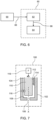
- FIG. 3 schematically illustrates a fuel injector 30 according to another example of this disclosure.
- the force transfer arrangement 32 comprises a separate component which subjects the needle 34 to said rotational force.
- the force transfer arrangement 32 may comprise a torsion spring which is operatively arranged between the nozzle body 36 and the needle 34, wherein the torsion spring subjects the needle 34 to said rotational force.
- the force transfer arrangement 32 in the form of a torsion spring may at one end 38 be provided with a pin which is engaged with a hole in the needle 34 (or a component connected to the needle 34 ), and may at another end 40 be engaged with a locating dowel 42 which in turn is connected to the nozzle body 36.
- a torsion spring is just one example of a resilient element which can subject the needle 34 to the rotational force.
- the force transfer arrangement 32 may comprise a different resilient element which subjects the needle 34 to the rotational force.
- protrusions may be provided to ends of a compression spring.
- the ends of the compression spring may be connected to two different parts (e.g., nozzle body and needle) which are rotated relative to each other to bias the compression spring torsionally before the parts are assembled together. As schematically illustrated in FIG.
- the force transfer arrangement 32 in this example the torsion spring, is thus configured to provide to the needle 34 a rotational force relative to the longitudinal axis X of the needle 34. This rotational force biases the needle 34 to assume a fixed rotational position at said rotational stop (relative to nozzle body), in the closed state of the fuel injector 30. If the needle 34 has not yet come to the fixed rotational position when the needle 34 has come into contact with the nozzle seat 18, the force transfer arrangement 32, in the form of the torsion spring (or other resilient element), may be configured to rotate the needle 34 to said fixed rotational position.
- FIG. 3 illustrates a solid needle 34, thus indicative of the fuel flowing on the outside of the needle, i.e., between the needle 34 and the nozzle body 36
- a force transfer arrangement comprising a separate component such as a resilient element.
- the needle 34 may be provided with internal channels for leading the fuel at least a certain distance inside the needle 34 towards the outlet of the fuel injector 30.
- FIG. 4 schematically illustrates an example of a rotational stop 50 which may be implemented in a fuel injector according to at least some examples of this disclosure.
- the needle 52 may be provided with a protrusion 54 which projects into a slightly oversized recess 56 of the nozzle body 58.
- the opposite walls 60, 62 of the recesses 54 limit the rotation of the needle 52 in both the clockwise and counter-clockwise direction.
- the protrusion 54 will come in contact with one of the walls 60, 62 depending on in which direction the needle 52 is rotated.
- the needle 52 may instead be provided with a recess into which a protrusion of the nozzle body 58 extends.
- FIG. 5 schematically illustrates another example of a rotational stop 70 which may be implemented in a fuel injector according to at least some examples of this disclosure.
- the rotational stop includes a void 72 formed by a recess of the needle 74 facing a recess of the nozzle body 76.
- a ball 78 which has a large enough diameter so as to extend into both recesses that form the void 72, limits the clockwise and counter-clockwise rotation of the needle 74 relative to the nozzle body 76.
- the rotational stop 50, 70 is achieved by means of the opposing walls of each recess.
- One of the opposing recesses walls 60, 62 thus forms a first mechanical stop against continued rotation of the needle 52, 74 in one of the clockwise and counter-clockwise direction.
- the other one of the opposing walls 60, 62 forms a second mechanical stop against continued rotation of the needle 50, 70 in the opposite one of said clockwise and counter-clockwise direction.
- FIG. 4 has mainly been illustrated to show a rotational stop 50, it should be understood that FIG. 4 may, in another interpretation, instead be considered to show a very schematic representation of the mutually cooperating axial guide elements discussed previously.
- the mutually cooperating guide elements may include one protrusion 54 which cooperates with a recess 56, wherein the needle 52 is provided with the protrusion 54 and the nozzle body 58 is provided with the recesses.
- such mutually cooperating axial guide elements may include more protrusions cooperating with respective recesses.
- the one or more protrusions may, in some examples, be provided on the nozzle body, while the one or more recesses are provided in the needle.
- FIG. 6 schematically illustrates an internal combustion engine system 80 according to one example of this disclosure.
- the internal combustion engine system 80 comprises a fuel injector 82, such as the fuel injector 10, 30 exemplified in FIG. 2 or FIG. 3 , or a fuel injector according to any other example of this disclosure.
- the internal combustion engine system 80 further comprises at least one combustion chamber 84.
- the fuel injector 82 is configured to, in the open state, inject fuel 86 into the combustion chamber 84. However, the fuel injector 82 may be normally in the closed state, and may be configured to become opened by an electrical signal 88 from an engine control module 90, ECM.
- FIG. 7 is another, more general, view of FIG. 1 , according to an example.
- FIG. 7 schematically illustrates a fuel injector 100 according to a general example of this disclosure.
- the fuel injector 100 comprises:
- Example 1 A fuel injector, comprising:
- Example 2 The fuel injector of example 1, wherein the force transfer arrangement forms part of the needle in the form of one or more angled peripheral surfaces of the needle, wherein kinetic energy of fuel flowing on said angled peripheral surfaces results in said rotational force being provided to the needle.
- Example 3 The fuel injector of any one of examples 1-2, wherein the force transfer arrangement comprises one or more grooves provided on the surface of the needle, the one or more grooves being tilted relative to said longitudinal axis, wherein fuel flowing along the needle and on the tilted groove(s) provides for said rotational force.
- Example 4 The fuel injector of example 1, wherein the force transfer arrangement comprises a separate component which subjects the needle to said rotational force.
- Example 5 The fuel injector of any one of examples 1 or 4, wherein the force transfer arrangement comprises a resilient element which subjects the needle to said rotational force.
- Example 6 The fuel injector of example 5, wherein the resilient element is in the form of a torsion spring arranged between the nozzle body and the needle, wherein the torsion spring subjects the needle to said rotational force.
- Example 7 The fuel injector of any one of examples 1-6, wherein the mutually cooperating axial guide elements include one or more protrusions cooperating with respective recesses, wherein one of the nozzle body and the needle is provided with said one or more protrusions and the other one of the nozzle body and the needle is provided with said respective recesses.
- Example 8 The fuel injector of any one of examples 1-7, wherein the force transfer arrangement is configured to start rotating the needle before it reaches the nozzle seat.
- Example 9 The fuel injector of any one of examples 1-8, wherein the force transfer arrangement is configured to rotate the needle to said fixed rotational position when the needle has come into contact with the nozzle seat.
- Example 10 The fuel injector of any one of examples 1-9, wherein said rotational stop is a single mechanical stop against continued rotation of the needle in one of a clockwise and counter-clockwise direction.
- Example 11 The fuel injector of any one of examples 1-9, wherein said rotational stop is a first mechanical stop against continued rotation of the needle in one of a clockwise and counter-clockwise direction, wherein the fuel injection further comprises a second mechanical stop against continued rotation of the needle in the opposite one of said clockwise and counter-clockwise direction.
- Example 12 The fuel injector of any one of examples 1-11, wherein the fuel injector is normally in the closed state, and is configured to become opened by an electrical signal from an engine control module, ECM.
- ECM engine control module
- Example 13 The fuel injector of any one of examples 1-12, wherein the needle is solid, wherein the fuel is allowed to flow along the outside of the needle.
- Example 14 The fuel injector of any one of examples 1-12, wherein the needle includes one or more internal channels for allowing the fuel to flow at least partly along the inside of the needle.
- Example 15 The fuel injector of any one of examples 1-14, wherein the rotational stop limits said rotational play to 3° or less, such as 1° or less, for example 0.5° or less.
- Example 16 An internal combustion engine system comprising the fuel injector according to any one of examples 1-15, wherein the fuel injector is configured to, in the open state, inject fuel into a combustion chamber of the internal combustion engine system.
- Example 17 A vehicle comprising the fuel injector according to any one of examples 1-15 or the internal combustion engine system according to example 16.
- Relative terms such as “below” or “above” or “upper” or “lower” or “horizontal” or “vertical” may be used herein to describe a relationship of one element to another element as illustrated in the Figures. It will be understood that these terms and those discussed above are intended to encompass different orientations of the device in addition to the orientation depicted in the Figures. It will be understood that when an element is referred to as being “connected” or “coupled” to another element, it can be directly connected or coupled to the other element, or intervening elements may be present. In contrast, when an element is referred to as being “directly connected” or “directly coupled” to another element, there are no intervening elements present.
Landscapes
- Engineering & Computer Science (AREA)
- Chemical & Material Sciences (AREA)
- Combustion & Propulsion (AREA)
- Mechanical Engineering (AREA)
- General Engineering & Computer Science (AREA)
- Fuel-Injection Apparatus (AREA)
Abstract
A fuel injector comprises a needle movable within a nozzle body. The fuel injector has a closed state in which the needle is mated with a nozzle seat, and an open state in which the needle is spaced apart from the nozzle seat to allow fuel to be dispensed from the nozzle body. The needle and the nozzle body have mutually cooperating axial guide elements that guide the needle along a geometrical longitudinal axis of the needle. The guide elements present, with respect to said longitudinal axis, a rotational play between the needle and the nozzle body. A rotational stop is provided to limit the rotational play. The fuel injector further comprises a force transfer arrangement configured to provide to the needle a rotational force relative to said longitudinal axis, the rotational force biasing the needle to assume a fixed rotational position at said rotational stop relative to the nozzle body in said closed state of the fuel injector.
Description
- The disclosure relates generally to a fuel injector. In particular aspects, the disclosure relates to a fuel injector for an internal combustion engine system. The disclosure can be applied to heavy-duty vehicles, such as trucks, buses, and construction equipment, among other vehicle types. Although the disclosure may be described with respect to a particular vehicle, the disclosure is not restricted to any particular vehicle.
- Fuel injectors for internal combustion engines normally include a needle that is movable within a nozzle body. The needle can be moved to contact a nozzle seat to close the fuel injector, and moved away from the nozzle seat to allow fuel to be injected into the internal combustion engine. Such known injectors may have a mechanical spline-like keying feature between the needle and the nozzle body which limits the range of rotation of the needle relative to the nozzle body. This promotes uneven wear of the contact surfaces such that, over time, a random pattern of convex and concave irregularities develops on one contact surface that tends to match a similar but opposing pattern of convex/concave irregularities on the opposite contact surface. The matching of those patterns promotes a fluid seal in the seat. However, the spline-like interface between the needle and the nozzle body is provided with a certain clearance to avoid undue friction that can disturb the accurately controlled axial movement of the needle relative to the nozzle body. This clearance allows a certain relative angular/rotational movement of the needle relative to the nozzle body. Such variation in relative angular/rotational position means that the formed irregularities in the contact surfaces will not always mate well enough to provide a tight seal, thereby presenting a risk of increased fuel leakage.
- According to a first aspect of the disclosure, there is provided a fuel injector, comprising:
- a nozzle body having an inlet for receiving fuel and an outlet for dispensing received fuel,
- a nozzle seat located within the nozzle body,
- a needle being movable within the nozzle body, selectively towards and away from the nozzle seat, wherein the fuel injector has:
- a closed state in which the needle is mated with the nozzle seat to prevent fuel from being dispensed from the nozzle body, and
- an open state in which the needle is spaced apart from the nozzle seat to allow fuel to be dispensed from the nozzle body,
- wherein the needle and the nozzle body have mutually cooperating axial guide elements that guide the needle along a geometrical longitudinal axis of the needle,
- wherein the guide elements present, with respect to said longitudinal axis, a rotational play between the needle and the nozzle body,
- wherein a rotational stop is provided to limit the rotational play,
- wherein the fuel injector further comprises:
- a force transfer arrangement configured to provide to the needle a rotational force relative to said longitudinal axis, the rotational force biasing the needle to assume a fixed rotational position at said rotational stop relative to the nozzle body in said closed state of the fuel injector.
- The rotational stop may be conceived in various manners. For example, in some examples the rotational stop may include a protrusion cooperating with a recess, such as a protrusion extending from one of said needle and said nozzle body and a cooperating (and slightly larger) recess provided in the other one of said needle and said nozzle body. In some examples, the rotational stop may include a void formed by a first recess in the needle facing a second recess in the nozzle body, wherein an element, such as a ball, may be provided in the void and dimensioned such that it extends into both recesses, thereby limiting the relative rotation between the needle and nozzle body. Yet another example for a rotational stop may be to provide a ratchet-configuration, which would limit rotation in one direction, wherein a torsional spring could be provided to limit rotation in the opposite direction.
- Optionally in some examples, including in at least one preferred example, the force transfer arrangement forms part of the needle in the form of one or more angled peripheral surfaces of the needle, wherein kinetic energy of fuel flowing on said angled peripheral surfaces results in said rotational force being provided to the needle. A technical benefit may include that no separate force transfer arrangement needs to be provided, but instead the existing kinetic energy of the flowing fuel is made use of.
- Optionally in some examples, including in at least one preferred example, the force transfer arrangement comprises one or more grooves provided on the surface of the needle, the one or more grooves being tilted relative to said longitudinal axis, wherein fuel flowing along the needle and on the tilted groove(s) provides for said rotational force. Analogously to the above discussion, a technical benefit may include that no separate force transfer arrangement needs to be provided for achieving the biasing of the needle.
- Optionally in some examples, including in at least one preferred example, the force transfer arrangement comprises a separate component which subjects the needle to said rotational force. A technical benefit may include that a separate component can provide a force independently of any fuel flow being present or not around the needle. For example, if the needle has already reached the nozzle seat, but the rotational position is such that the irregularities in the contact surfaces of the needle and the nozzle seat are not matching, then there may be a small leakage, but the force of the fuel will be very low and may not be able to rotate the needle into its final matching position. By providing a separate component to provide the force, the biasing force can be applied to the needle even after it has come into contact with the nozzle seat.
- Optionally in some examples, including in at least one preferred example, the force transfer arrangement comprises a resilient element which subjects the needle to said rotational force. Analogously with the above, a technical benefit may include that a resilient element may provide the biasing force to the needle even after it has come into contact with the nozzle seat.
- Optionally in some examples, including in at least one preferred example, the resilient element is in the form of a torsion spring arranged between the nozzle body and the needle, wherein the torsion spring subjects the needle to said rotational force. A technical benefit may include that torsion springs are readily available and, analogously with the above discussion, provides the biasing force to the needle irrespective of the axial position of the needle.
- Optionally in some examples, including in at least one preferred example, the mutually cooperating axial guide elements include one or more protrusions cooperating with respective recesses, wherein one of the nozzle body and the needle is provided with said one or more protrusions and the other one of the nozzle body and the needle is provided with said respective recesses. A technical benefit may include that such axial guide elements are simple to manufacture, yet provide efficient axial guiding. The protrusions and recesses may be in the form of splines, keys, grooves, etc. For axial guiding, suitably at least one of said protrusions and recesses may be elongate and extend in parallel with the central axis of the fuel injector. For example, a protrusion which has a relatively short axial extension, can be guided along a recess/groove having relatively long axial extension. Such a long recess may in some examples be provided in the needle, and in other examples be provided in the nozzle body. Conversely, in other examples, the protrusion may have a relatively long axial extension and the recess may have a relatively short axial extension. It should furthermore be understood, that in some examples, the protrusion as well as the recess may both be elongate in the axial extension, for example, of equal axial length. In other examples the mutually cooperating axial guide elements may include cylindrical guide surfaces cooperating with each other.
- Optionally in some examples, including in at least one preferred example, the force transfer arrangement is configured to start rotating the needle before it reaches the nozzle seat. A technical benefit may include that, by allowing the needle to be rotated before having reached the seated state, various factors such as vibrations pushing away the needle at the last moment, may be avoided.
- Optionally in some examples, including in at least one preferred example, the force transfer arrangement is configured to rotate the needle to said fixed rotational position when the needle has come into contact with the nozzle seat. A technical benefit may include that a correct position may be provided even if the correct rotational position has not yet been reached during the axial movement of the needle. It should thus be understood that the rotational biasing force may, in at least some examples, start already before the needle comes into contact with the nozzle seat, and then also continue after the needle has come into contact with the nozzle seat.
- Optionally in some examples, including in at least one preferred example, said rotational stop is a single mechanical stop against continued rotation of the needle in one of a clockwise and counter-clockwise direction. A technical benefit may include that more play is allowed in the opposite direction, reducing the risk of frictional effects. In some examples, the rotation in the opposite direction may be limited by a spring force, such as from the previously discussed resilient element/torsion spring, and therefore in the opposite direction there would not be a limit at a particular fixed rotational position.
- Optionally in some examples, including in at least one preferred example, said rotational stop is a first mechanical stop against continued rotation of the needle in one of a clockwise and counter-clockwise direction, wherein the fuel injection further comprises a second mechanical stop against continued rotation of the needle in the opposite one of said clockwise and counter-clockwise direction. A technical benefit may include that by having a limit in both rotational directions, the energy required to rotate the needle from one rotational end point to the other rotational end point may be conveniently controlled and anticipated.
- Optionally in some examples, including in at least one preferred example, the fuel injector is normally in the closed state, and is configured to become opened by an electrical signal from an engine control module, ECM. A technical benefit may include that such control is efficient and provides short response time.
- According to a second aspect of the disclosure, there is provided an internal combustion engine system comprising the fuel injector according to the first aspect, including any examples thereof, wherein the fuel injector is configured to, in the open state, inject fuel into a combustion chamber of the internal combustion engine system. The second aspect of the disclosure may seek to solve the corresponding problem and may include the corresponding benefits as the first aspect, including any examples thereof.
- According to a third aspect of the disclosure, there is provided a vehicle comprising the fuel injector according to the first aspect, including any examples thereof, or internal combustion engine system according to the second aspect, including any examples thereof. The third aspect of the disclosure may seek to solve the corresponding problem and may include the corresponding benefits as the first aspect, including any examples thereof.
- The disclosed aspects, examples (including any preferred examples), and/or accompanying claims may be suitably combined with each other as would be apparent to anyone of ordinary skill in the art. Additional features and advantages are disclosed in the following description, claims, and drawings, and in part will be readily apparent therefrom to those skilled in the art or recognized by practicing the disclosure as described herein.
- Examples are described in more detail below with reference to the appended drawings.
-
FIG. 1 schematically illustrates a vehicle according to one example of this disclosure. -
FIG. 2 schematically illustrates a fuel injector according to one example of this disclosure. -
FIG. 3 schematically illustrates a fuel injector according to another example of this disclosure. -
FIG. 4 schematically illustrates an example of a rotational stop which may be implemented in a fuel injector according to at least some examples of this disclosure. -
FIG. 5 schematically illustrates another example of a rotational stop which may be implemented in a fuel injector according to at least some examples of this disclosure. -
FIG. 6 schematically illustrates an internal combustion engine system according to one example of this disclosure. -
FIG. 7 schematically illustrates a fuel injector according to a general example of this disclosure. - The detailed description set forth below provides information and examples of the disclosed technology with sufficient detail to enable those skilled in the art to practice the disclosure.
- A fuel injector may be provided for supplying fuel into a cylinder of an internal combustion engine. The fuel injector may be inserted into an opening in a housing part to form a part of a fuel injection system. Such a fuel injector or fuel injection system may be used in an internal combustion engine, such as a diesel engine, wherein said engine can be used in any vehicle, such as a truck, bus, construction equipment, etc. A fuel injector may include a needle that is movable within a nozzle body. The needle can be moved to contact a nozzle seat to close the fuel injector, and moved away from the nozzle seat to allow fuel to be injected into the internal combustion engine. Known injectors may be subject to uneven wear of the contact surfaces between the needle and the nozzle seat such that, over time, a random pattern of convex and concave irregularities develops on one contact surface that tends to match a similar but opposing pattern of convex/concave irregularities on the opposite contact surface. The matching of those patterns promotes a fluid seal in the seat. However, the needle and the nozzle body are provided with a certain clearance which allows a certain relative angular/rotational movement of the needle relative to the nozzle body. Such variation in relative angular/rotational position means that the formed irregularities in the contact surfaces will not always mate well enough to provide a tight seal, thereby presenting a risk of increased fuel leakage. The present disclosure is based on the insight that a repeatable position is obtainable by combining a rotational stop with a force transfer arrangement, such that the needle may each time it is subjected to the rotational force provided by the force transfer arrangement always assume a fixed rotational position at the rotational stop in the closed state of the fuel injector. Thus, by forcing the needle to arrive to a predetermined position in the closed state of the fuel injector, uncertainty and variability of relative rotational orientation between contact surfaces may efficiently be avoided.
-
FIG. 1 schematically illustrates avehicle 1 according to one example of this disclosure. The exemplary illustration inFIG. 1 shows a tractor unit for towing a trailer unit (not shown), which together make up a semitrailer vehicle. However, the teachings of this disclosure are applicable to other types of vehicles as well. For instance, the vehicle may be a different type of vehicle for cargo transport, such as a truck, or a truck with a dolly unit arranged to tow a trailer unit, etc. Other conceivable examples include a bus, construction equipment or other vehicle types. Thevehicle 1 may be powered by an internal combustion engine (ICE). The illustratedvehicle 1 comprises acabin 2 in which a driver may operate thevehicle 1. However, in other exemplary embodiments thevehicle 1 may be an autonomous, i.e., self-driving, vehicle. - The
vehicle 1 may comprise a fuel injector of this disclosure, some examples of which will be discussed below. In particular, thevehicle 1 may comprise an internal combustion engine system which in turn comprises a fuel injector of this disclosure. Such a fuel injector may be configured to, in the open state, inject fuel into a combustion chamber of the internal combustion engine system. -
FIG. 2 schematically illustrates afuel injector 10 according to one example of this disclosure. Thefuel injector 10 comprises anozzle body 12 having aninlet 14 for receiving fuel (indicated by arrows). Theinlet 14 may be connected to anozzle chamber 15 for receiving fuel to be injected. Thenozzle body 12 further hasoutlets 16 for dispensing received fuel. Anozzle seat 18 is located within thenozzle body 12. Thefuel injector 10 further comprises aneedle 20 which may be reciprocally movable within thenozzle body 12. In particular, theneedle 20 may be selectively movable towards and away from thenozzle seat 18. Thefuel injector 10 has a closed state in which theneedle 20 is mated with thenozzle seat 18 to prevent fuel from being dispensed from thenozzle body 12, and an open state in which theneedle 20 is spaced apart from thenozzle seat 18 to allow fuel to be dispensed from thenozzle body 12. InFIG. 2 , the open state of thefuel injector 10 is shown. Thus, theneedle 20 has not reached its most axially advanced position. To change to a closed state of thefuel injector 10, theneedle 20 would be moved to an axially advanced position compared to that shown inFIG. 2 . Theneedle 20 may thus be movable between an advanced/closed position and a retracted/open position. A purpose of thenozzle seat 18 is to hydraulically separate thenozzle chamber 15 from theoutlets 16 in the closed position of theneedle 20, i.e., in the closed state of thefuel injector 10. Theneedle 20 and thenozzle body 12 may suitably be concentrically arranged relative to each other and may have a controlled clearance in aguide 22 between each other. Theguide 22 may be formed by mutually cooperating axial guide elements of theneedle 20 andnozzle body 12, respectively, which guide elements guide theneedle 20 along a geometrical longitudinal axis X of theneedle 20. The guide elements present, with respect to said longitudinal axis X, a rotational play between theneedle 20 and thenozzle body 12. As illustrated inFIG. 2 , the guide elements may, in some examples be formed by cooperating cylindrical surfaces of theneedle 20 andnozzle body 22. In other examples, the guide elements may include cooperating protrusions and recesses. -
FIG. 2 also illustrates schematically that thefuel injector 10 further comprises arotational stop 24. Therotational stop 24 is provided to limit the rotational play between theneedle 20 and thenozzle body 12. - The
fuel injector 10 further comprises aforce transfer arrangement 26 configured to provide to the needle 20 a rotational force relative to said longitudinal axis X. The purpose of the rotational force is to bias theneedle 20 into assuming, at saidrotational stop 24, a fixed rotational position relative to thenozzle body 12 in the closed state of thefuel injector 10. Thus, theneedle 20 may be rotated to a predetermined rotational orientation, defined by therotational stop 24, each time theneedle 20 forms contact with thenozzle seat 18 in the closed state of thefuel injector 10. - In the illustrated example in
FIG. 2 , theforce transfer arrangement 26 may form part of theneedle 20 in the form of one or more angled peripheral surfaces of theneedle 20. The kinetic energy of fuel flowing (indicated by the arrows) on said angled peripheral surfaces results in said rotational force being provided to theneedle 20. Thus, when theneedle 20 is in a lifted position and fuel is being injected, as the fluid passes along the angled peripheral surfaces, theneedle 20 may be rotated into the desired position, such that when theneedle 20 is subsequently lowered to come into contact with thenozzle seat 18, it will assume the fixed (predetermined) rotational position. Thus, theforce transfer arrangement 26 may be configured to start rotating theneedle 20 before it reaches thenozzle seat 18. - From the above, it can be understood that, as illustrated in
FIG. 2 , in at least some examples, theneedle 20 may present a section with peripheral angled cuts acting as fuel flow channels. Thus, as illustrated in the example ofFIG. 2 , theforce transfer arrangement 26 may comprise one or more groves provided on the surface of theneedle 20, the one or more grooves being tilted relative to said longitudinal axis X. Hereby, when the fuel flows along theneedle 20 and on the tilted groove or grooves, the kinetic energy of the fuel will provide for said rotational force. -
FIG. 3 schematically illustrates afuel injector 30 according to another example of this disclosure. In this example theforce transfer arrangement 32 comprises a separate component which subjects theneedle 34 to said rotational force. In particular,FIG. 3 very schematically indicates that theforce transfer arrangement 32 may comprise a torsion spring which is operatively arranged between thenozzle body 36 and theneedle 34, wherein the torsion spring subjects theneedle 34 to said rotational force. For example, theforce transfer arrangement 32 in the form of a torsion spring may at oneend 38 be provided with a pin which is engaged with a hole in the needle 34 (or a component connected to the needle 34), and may at anotherend 40 be engaged with a locatingdowel 42 which in turn is connected to thenozzle body 36. It should, however, be understood that other ways of mounting the torsion spring are readily conceivable. It should furthermore be understood that a torsion spring is just one example of a resilient element which can subject theneedle 34 to the rotational force. In other examples, theforce transfer arrangement 32 may comprise a different resilient element which subjects theneedle 34 to the rotational force. For instance, instead of a torsion spring, it would be conceivable to provide protrusions to ends of a compression spring. The ends of the compression spring may be connected to two different parts (e.g., nozzle body and needle) which are rotated relative to each other to bias the compression spring torsionally before the parts are assembled together. As schematically illustrated inFIG. 3 , also in this example there is provided arotational stop 24 to limit the rotational play. Theforce transfer arrangement 32, in this example the torsion spring, is thus configured to provide to the needle 34 a rotational force relative to the longitudinal axis X of theneedle 34. This rotational force biases theneedle 34 to assume a fixed rotational position at said rotational stop (relative to nozzle body), in the closed state of thefuel injector 30. If theneedle 34 has not yet come to the fixed rotational position when theneedle 34 has come into contact with thenozzle seat 18, theforce transfer arrangement 32, in the form of the torsion spring (or other resilient element), may be configured to rotate theneedle 34 to said fixed rotational position. - It should be noted that although
FIG. 3 illustrates asolid needle 34, thus indicative of the fuel flowing on the outside of the needle, i.e., between theneedle 34 and thenozzle body 36, it should be understood that other needle configurations may be combinable with a force transfer arrangement comprising a separate component such as a resilient element. For instance, theneedle 34 may be provided with internal channels for leading the fuel at least a certain distance inside theneedle 34 towards the outlet of thefuel injector 30. -
FIG. 4 schematically illustrates an example of arotational stop 50 which may be implemented in a fuel injector according to at least some examples of this disclosure. In this example, it is very schematically illustrated that theneedle 52 may be provided with aprotrusion 54 which projects into a slightlyoversized recess 56 of thenozzle body 58. Theopposite walls recesses 54 limit the rotation of theneedle 52 in both the clockwise and counter-clockwise direction. In particular, theprotrusion 54 will come in contact with one of thewalls needle 52 is rotated. In other examples, theneedle 52 may instead be provided with a recess into which a protrusion of thenozzle body 58 extends. -
FIG. 5 schematically illustrates another example of arotational stop 70 which may be implemented in a fuel injector according to at least some examples of this disclosure. In this example, the rotational stop includes a void 72 formed by a recess of theneedle 74 facing a recess of thenozzle body 76. Aball 78 which has a large enough diameter so as to extend into both recesses that form the void 72, limits the clockwise and counter-clockwise rotation of theneedle 74 relative to thenozzle body 76. - In both examples in
FIG. 4 and FIG. 5 , therotational stop recesses walls needle walls needle - Although
FIG. 4 has mainly been illustrated to show arotational stop 50, it should be understood thatFIG. 4 may, in another interpretation, instead be considered to show a very schematic representation of the mutually cooperating axial guide elements discussed previously. Thus, the mutually cooperating guide elements may include oneprotrusion 54 which cooperates with arecess 56, wherein theneedle 52 is provided with theprotrusion 54 and thenozzle body 58 is provided with the recesses. It should be understood that, in some examples, such mutually cooperating axial guide elements may include more protrusions cooperating with respective recesses. Furthermore, the one or more protrusions may, in some examples, be provided on the nozzle body, while the one or more recesses are provided in the needle. -
FIG. 6 schematically illustrates an internalcombustion engine system 80 according to one example of this disclosure. The internalcombustion engine system 80 comprises afuel injector 82, such as thefuel injector FIG. 2 orFIG. 3 , or a fuel injector according to any other example of this disclosure. The internalcombustion engine system 80 further comprises at least onecombustion chamber 84. Thefuel injector 82 is configured to, in the open state, injectfuel 86 into thecombustion chamber 84. However, thefuel injector 82 may be normally in the closed state, and may be configured to become opened by anelectrical signal 88 from anengine control module 90, ECM. -
FIG. 7 is another, more general, view ofFIG. 1 , according to an example. In particularFIG. 7 schematically illustrates afuel injector 100 according to a general example of this disclosure. Thefuel injector 100 comprises: - a
nozzle body 102 having aninlet 104 for receiving fuel and anoutlet 106 for dispensing received fuel, - a
nozzle seat 108 located within thenozzle body 102, - a
needle 110 being movable within thenozzle body 102, selectively towards and away from thenozzle seat 108, wherein thefuel injector 100 has:- a closed state in which the
needle 110 is mated with thenozzle seat 108 to prevent fuel from being dispensed from thenozzle body 102, and - an open state in which the
needle 110 is spaced apart from thenozzle seat 108 to allow fuel to be dispensed from thenozzle body 102, - wherein the
needle 110 and thenozzle body 102 have mutually cooperatingaxial guide elements needle 110 along a geometrical longitudinal axis X of theneedle 110, - wherein the
guide elements needle 110 and thenozzle body 102, - wherein a
rotational stop 116 is provided to limit the rotational play, - wherein the
fuel injector 100 further comprises:- a
force transfer arrangement 118 configured to provide to the needle 110 a rotational force relative to said longitudinal axis X , the rotational force biasing theneedle 110 to assume a fixed rotational position at saidrotational stop 116 relative to thenozzle body 102 in said closed state of thefuel injector 110.
- a
- a closed state in which the
- Example 1: A fuel injector, comprising:
- a nozzle body having an inlet for receiving fuel and an outlet for dispensing received fuel,
- a nozzle seat located within the nozzle body,
- a needle being movable within the nozzle body, selectively towards and away from the nozzle seat, wherein the fuel injector has:
- a closed state in which the needle is mated with the nozzle seat to prevent fuel from being dispensed from the nozzle body, and
- an open state in which the needle is spaced apart from the nozzle seat to allow fuel to be dispensed from the nozzle body,
- wherein the needle and the nozzle body have mutually cooperating axial guide elements that guide the needle along a geometrical longitudinal axis of the needle,
- wherein the guide elements present, with respect to said longitudinal axis, a rotational play between the needle and the nozzle body,
- wherein a rotational stop is provided to limit the rotational play,
- wherein the fuel injector further comprises:
- a force transfer arrangement configured to provide to the needle a rotational force relative to said longitudinal axis, the rotational force biasing the needle to assume a fixed rotational position at said rotational stop relative to the nozzle body in said closed state of the fuel injector.
- Example 2: The fuel injector of example 1, wherein the force transfer arrangement forms part of the needle in the form of one or more angled peripheral surfaces of the needle, wherein kinetic energy of fuel flowing on said angled peripheral surfaces results in said rotational force being provided to the needle.
- Example 3: The fuel injector of any one of examples 1-2, wherein the force transfer arrangement comprises one or more grooves provided on the surface of the needle, the one or more grooves being tilted relative to said longitudinal axis, wherein fuel flowing along the needle and on the tilted groove(s) provides for said rotational force.
- Example 4: The fuel injector of example 1, wherein the force transfer arrangement comprises a separate component which subjects the needle to said rotational force.
- Example 5: The fuel injector of any one of examples 1 or 4, wherein the force transfer arrangement comprises a resilient element which subjects the needle to said rotational force.
- Example 6: The fuel injector of example 5, wherein the resilient element is in the form of a torsion spring arranged between the nozzle body and the needle, wherein the torsion spring subjects the needle to said rotational force.
- Example 7: The fuel injector of any one of examples 1-6, wherein the mutually cooperating axial guide elements include one or more protrusions cooperating with respective recesses, wherein one of the nozzle body and the needle is provided with said one or more protrusions and the other one of the nozzle body and the needle is provided with said respective recesses.
- Example 8: The fuel injector of any one of examples 1-7, wherein the force transfer arrangement is configured to start rotating the needle before it reaches the nozzle seat.
- Example 9: The fuel injector of any one of examples 1-8, wherein the force transfer arrangement is configured to rotate the needle to said fixed rotational position when the needle has come into contact with the nozzle seat.
- Example 10: The fuel injector of any one of examples 1-9, wherein said rotational stop is a single mechanical stop against continued rotation of the needle in one of a clockwise and counter-clockwise direction.
- Example 11: The fuel injector of any one of examples 1-9, wherein said rotational stop is a first mechanical stop against continued rotation of the needle in one of a clockwise and counter-clockwise direction, wherein the fuel injection further comprises a second mechanical stop against continued rotation of the needle in the opposite one of said clockwise and counter-clockwise direction.
- Example 12: The fuel injector of any one of examples 1-11, wherein the fuel injector is normally in the closed state, and is configured to become opened by an electrical signal from an engine control module, ECM.
- Example 13: The fuel injector of any one of examples 1-12, wherein the needle is solid, wherein the fuel is allowed to flow along the outside of the needle.
- Example 14: The fuel injector of any one of examples 1-12, wherein the needle includes one or more internal channels for allowing the fuel to flow at least partly along the inside of the needle.
- Example 15. The fuel injector of any one of examples 1-14, wherein the rotational stop limits said rotational play to 3° or less, such as 1° or less, for example 0.5° or less.
- Example 16: An internal combustion engine system comprising the fuel injector according to any one of examples 1-15, wherein the fuel injector is configured to, in the open state, inject fuel into a combustion chamber of the internal combustion engine system.
- Example 17: A vehicle comprising the fuel injector according to any one of examples 1-15 or the internal combustion engine system according to example 16.
- The terminology used herein is for the purpose of describing particular aspects only and is not intended to be limiting of the disclosure. As used herein, the singular forms "a," "an," and "the" are intended to include the plural forms as well, unless the context clearly indicates otherwise. As used herein, the term "and/or" includes any and all combinations of one or more of the associated listed items. It will be further understood that the terms "comprises," "comprising," "includes," and/or "including" when used herein specify the presence of stated features, integers, actions, steps, operations, elements, and/or components, but do not preclude the presence or addition of one or more other features, integers, actions, steps, operations, elements, components, and/or groups thereof.
- It will be understood that, although the terms first, second, etc., may be used herein to describe various elements, these elements should not be limited by these terms. These terms are only used to distinguish one element from another. For example, a first element could be termed a second element, and, similarly, a second element could be termed a first element without departing from the scope of the present disclosure.
- Relative terms such as "below" or "above" or "upper" or "lower" or "horizontal" or "vertical" may be used herein to describe a relationship of one element to another element as illustrated in the Figures. It will be understood that these terms and those discussed above are intended to encompass different orientations of the device in addition to the orientation depicted in the Figures. It will be understood that when an element is referred to as being "connected" or "coupled" to another element, it can be directly connected or coupled to the other element, or intervening elements may be present. In contrast, when an element is referred to as being "directly connected" or "directly coupled" to another element, there are no intervening elements present.
- Unless otherwise defined, all terms (including technical and scientific terms) used herein have the same meaning as commonly understood by one of ordinary skill in the art to which this disclosure belongs. It will be further understood that terms used herein should be interpreted as having a meaning consistent with their meaning in the context of this specification and the relevant art and will not be interpreted in an idealized or overly formal sense unless expressly so defined herein.
- It is to be understood that the present disclosure is not limited to the aspects described above and illustrated in the drawings; rather, the skilled person will recognize that many changes and modifications may be made within the scope of the present disclosure and appended claims. In the drawings and specification, there have been disclosed aspects for purposes of illustration only and not for purposes of limitation, the scope of the disclosure being set forth in the following claims.
Claims (13)
- A fuel injector, comprising:- a nozzle body having an inlet for receiving fuel and an outlet for dispensing received fuel,- a nozzle seat located within the nozzle body,- a needle being movable within the nozzle body, selectively towards and away from the nozzle seat, wherein the fuel injector has:a closed state in which the needle is mated with the nozzle seat to prevent fuel from being dispensed from the nozzle body, andan open state in which the needle is spaced apart from the nozzle seat to allow fuel to be dispensed from the nozzle body,wherein the needle and the nozzle body have mutually cooperating axial guide elements that guide the needle along a geometrical longitudinal axis of the needle,wherein the guide elements present, with respect to said longitudinal axis, a rotational play between the needle and the nozzle body,wherein a rotational stop is provided to limit the rotational play,wherein the fuel injector further comprises:- a force transfer arrangement configured to provide to the needle a rotational force relative to said longitudinal axis, the rotational force biasing the needle to assume a fixed rotational position at said rotational stop relative to the nozzle body in said closed state of the fuel injector.
- The fuel injector of claim 1, wherein the force transfer arrangement forms part of the needle in the form of one or more angled peripheral surfaces of the needle, wherein kinetic energy of fuel flowing on said angled peripheral surfaces results in said rotational force being provided to the needle.
- The fuel injector of any one of claims 1-2, wherein the force transfer arrangement comprises one or more grooves provided on the surface of the needle, the one or more grooves being tilted relative to said longitudinal axis, wherein fuel flowing along the needle and on the tilted groove(s) provides for said rotational force.
- The fuel injector of claim 1, wherein the force transfer arrangement comprises a separate component which subjects the needle to said rotational force.
- The fuel injector of any one of claims 1 or 4, wherein the force transfer arrangement comprises a resilient element which subjects the needle to said rotational force.
- The fuel injector of claim 5, wherein the resilient element is in the form of a torsion spring arranged between the nozzle body and the needle, wherein the torsion spring subjects the needle to said rotational force.
- The fuel injector of any one of claims 1-6, wherein the mutually cooperating axial guide elements include one or more protrusions cooperating with respective recesses, wherein one of the nozzle body and the needle is provided with said one or more protrusions and the other one of the nozzle body and the needle is provided with said respective recesses.
- The fuel injector of any one of claims 1-7, wherein the force transfer arrangement is configured to start rotating the needle before it reaches the nozzle seat.
- The fuel injector of any one of claims 1-8, wherein the force transfer arrangement is configured to rotate the needle to said fixed rotational position when the needle has come into contact with the nozzle seat.
- The fuel injector of any one of claims 1-9, wherein said rotational stop is a first mechanical stop against continued rotation of the needle in one of a clockwise and counter-clockwise direction, wherein the fuel injection further comprises a second mechanical stop against continued rotation of the needle in the opposite one of said clockwise and counter-clockwise direction.
- The fuel injector of any one of claims 1-10, wherein the fuel injector is normally in the closed state, and is configured to become opened by an electrical signal from an engine control module, ECM.
- An internal combustion engine system comprising the fuel injector according to any one of claims 1-11, wherein the fuel injector is configured to, in the open state, inject fuel into a combustion chamber of the internal combustion engine system.
- A vehicle comprising the fuel injector according to any one of claims 1-11 or the internal combustion engine system according to claim 12.
Priority Applications (1)
| Application Number | Priority Date | Filing Date | Title |
|---|---|---|---|
| EP23208103.4A EP4553313A1 (en) | 2023-11-07 | 2023-11-07 | A fuel injector |
Applications Claiming Priority (1)
| Application Number | Priority Date | Filing Date | Title |
|---|---|---|---|
| EP23208103.4A EP4553313A1 (en) | 2023-11-07 | 2023-11-07 | A fuel injector |
Publications (1)
| Publication Number | Publication Date |
|---|---|
| EP4553313A1 true EP4553313A1 (en) | 2025-05-14 |
Family
ID=88731607
Family Applications (1)
| Application Number | Title | Priority Date | Filing Date |
|---|---|---|---|
| EP23208103.4A Pending EP4553313A1 (en) | 2023-11-07 | 2023-11-07 | A fuel injector |
Country Status (1)
| Country | Link |
|---|---|
| EP (1) | EP4553313A1 (en) |
Citations (5)
| Publication number | Priority date | Publication date | Assignee | Title |
|---|---|---|---|---|
| DE3139288A1 (en) * | 1981-10-02 | 1983-04-21 | Robert Bosch Gmbh, 7000 Stuttgart | Fuel injection nozzle for internal combustion engines |
| US4382553A (en) * | 1980-03-11 | 1983-05-10 | Daimler-Benz Aktiengesellschaft | Fuel injection nozzle for an air-compressing internal combustion engine |
| US20030075619A1 (en) * | 2001-10-23 | 2003-04-24 | Jong-Bum Park | Fuel injector having a swirl regulator |
| FR2897396A1 (en) * | 2006-02-16 | 2007-08-17 | Renault Sas | CONTROL VALVE FOR CONTROL CHAMBER FOR NEEDLE INJECTOR FOR INTERNAL COMBUSTION ENGINE |
| US20210025363A1 (en) * | 2019-07-25 | 2021-01-28 | Hyundai Kefico Corporation | Vehicle fuel injector |
-
2023
- 2023-11-07 EP EP23208103.4A patent/EP4553313A1/en active Pending
Patent Citations (5)
| Publication number | Priority date | Publication date | Assignee | Title |
|---|---|---|---|---|
| US4382553A (en) * | 1980-03-11 | 1983-05-10 | Daimler-Benz Aktiengesellschaft | Fuel injection nozzle for an air-compressing internal combustion engine |
| DE3139288A1 (en) * | 1981-10-02 | 1983-04-21 | Robert Bosch Gmbh, 7000 Stuttgart | Fuel injection nozzle for internal combustion engines |
| US20030075619A1 (en) * | 2001-10-23 | 2003-04-24 | Jong-Bum Park | Fuel injector having a swirl regulator |
| FR2897396A1 (en) * | 2006-02-16 | 2007-08-17 | Renault Sas | CONTROL VALVE FOR CONTROL CHAMBER FOR NEEDLE INJECTOR FOR INTERNAL COMBUSTION ENGINE |
| US20210025363A1 (en) * | 2019-07-25 | 2021-01-28 | Hyundai Kefico Corporation | Vehicle fuel injector |
Similar Documents
| Publication | Publication Date | Title |
|---|---|---|
| DE112011100504B4 (en) | Pressurized swirl flow injector with reduced flow variability and reverse flow | |
| JP3881241B2 (en) | Fuel injector having a floating sleeve control chamber | |
| US5921475A (en) | Automotive fuel injector | |
| US6776358B2 (en) | Fuel injection nozzle for a diesel engine | |
| DE102004021117A1 (en) | Fuel injector | |
| EP4553313A1 (en) | A fuel injector | |
| US20150292462A1 (en) | Piezo Injector | |
| US20090056817A1 (en) | Fuel pressure regulator for vehicle | |
| US6988680B1 (en) | Injector of compact design for a common rail injection system for internal combustion engines | |
| US11976618B2 (en) | Fuel injection valve | |
| US5413281A (en) | Fuel injection nozzle for an internal combustion engine | |
| EP1092863A2 (en) | Pressure regulating valve for an accumulator-type fuel injection system for internal combustion engines | |
| US20080296415A1 (en) | Valve Body, Fluid Injector and Process for Manufacturing a Valve Body | |
| EP3055549B1 (en) | Plunger/fluid-line arrangement, in particular control-plunger/control-bore arrangement | |
| US7036754B2 (en) | Injection valve | |
| EP1936180B1 (en) | Fuel injector valve | |
| US5081766A (en) | Method of making an electrically-operated fluid valve having improved sealing of the valve needle to the valve seat when the valve is closed | |
| US6216964B1 (en) | Fuel injector | |
| WO2013041664A1 (en) | Pressure control system and pressure control valve | |
| US20090126689A1 (en) | Fuel injector having valve with opposing sealing surfaces | |
| US4830285A (en) | Fuel injection nozzle | |
| DE102021129608A1 (en) | SPLIT CONTROL ASSEMBLY WITH TRAPPED VOLUME IN FUEL INJECTOR | |
| EP1264983B1 (en) | Internal combustion engine fuel injector | |
| US6561223B2 (en) | Subdivided control valve body for injector control valve | |
| JP4191445B2 (en) | Injection valve |
Legal Events
| Date | Code | Title | Description |
|---|---|---|---|
| PUAI | Public reference made under article 153(3) epc to a published international application that has entered the european phase |
Free format text: ORIGINAL CODE: 0009012 |
|
| STAA | Information on the status of an ep patent application or granted ep patent |
Free format text: STATUS: THE APPLICATION HAS BEEN PUBLISHED |
|
| AK | Designated contracting states |
Kind code of ref document: A1 Designated state(s): AL AT BE BG CH CY CZ DE DK EE ES FI FR GB GR HR HU IE IS IT LI LT LU LV MC ME MK MT NL NO PL PT RO RS SE SI SK SM TR |