EP4553311A2 - Transmission and method for control of boost spool - Google Patents
Transmission and method for control of boost spool Download PDFInfo
- Publication number
- EP4553311A2 EP4553311A2 EP25167839.7A EP25167839A EP4553311A2 EP 4553311 A2 EP4553311 A2 EP 4553311A2 EP 25167839 A EP25167839 A EP 25167839A EP 4553311 A2 EP4553311 A2 EP 4553311A2
- Authority
- EP
- European Patent Office
- Prior art keywords
- spool
- gas turbine
- shaft
- power
- turbine engine
- Prior art date
- Legal status (The legal status is an assumption and is not a legal conclusion. Google has not performed a legal analysis and makes no representation as to the accuracy of the status listed.)
- Pending
Links
Images


Classifications
-
- F—MECHANICAL ENGINEERING; LIGHTING; HEATING; WEAPONS; BLASTING
- F02—COMBUSTION ENGINES; HOT-GAS OR COMBUSTION-PRODUCT ENGINE PLANTS
- F02C—GAS-TURBINE PLANTS; AIR INTAKES FOR JET-PROPULSION PLANTS; CONTROLLING FUEL SUPPLY IN AIR-BREATHING JET-PROPULSION PLANTS
- F02C9/00—Controlling gas-turbine plants; Controlling fuel supply in air- breathing jet-propulsion plants
- F02C9/26—Control of fuel supply
- F02C9/42—Control of fuel supply specially adapted for the control of two or more plants simultaneously
-
- F—MECHANICAL ENGINEERING; LIGHTING; HEATING; WEAPONS; BLASTING
- F02—COMBUSTION ENGINES; HOT-GAS OR COMBUSTION-PRODUCT ENGINE PLANTS
- F02C—GAS-TURBINE PLANTS; AIR INTAKES FOR JET-PROPULSION PLANTS; CONTROLLING FUEL SUPPLY IN AIR-BREATHING JET-PROPULSION PLANTS
- F02C3/00—Gas-turbine plants characterised by the use of combustion products as the working fluid
- F02C3/04—Gas-turbine plants characterised by the use of combustion products as the working fluid having a turbine driving a compressor
- F02C3/107—Gas-turbine plants characterised by the use of combustion products as the working fluid having a turbine driving a compressor with two or more rotors connected by power transmission
-
- F—MECHANICAL ENGINEERING; LIGHTING; HEATING; WEAPONS; BLASTING
- F02—COMBUSTION ENGINES; HOT-GAS OR COMBUSTION-PRODUCT ENGINE PLANTS
- F02C—GAS-TURBINE PLANTS; AIR INTAKES FOR JET-PROPULSION PLANTS; CONTROLLING FUEL SUPPLY IN AIR-BREATHING JET-PROPULSION PLANTS
- F02C7/00—Features, components parts, details or accessories, not provided for in, or of interest apart form groups F02C1/00 - F02C6/00; Air intakes for jet-propulsion plants
- F02C7/32—Arrangement, mounting, or driving, of auxiliaries
-
- F—MECHANICAL ENGINEERING; LIGHTING; HEATING; WEAPONS; BLASTING
- F02—COMBUSTION ENGINES; HOT-GAS OR COMBUSTION-PRODUCT ENGINE PLANTS
- F02C—GAS-TURBINE PLANTS; AIR INTAKES FOR JET-PROPULSION PLANTS; CONTROLLING FUEL SUPPLY IN AIR-BREATHING JET-PROPULSION PLANTS
- F02C7/00—Features, components parts, details or accessories, not provided for in, or of interest apart form groups F02C1/00 - F02C6/00; Air intakes for jet-propulsion plants
- F02C7/36—Power transmission arrangements between the different shafts of the gas turbine plant, or between the gas-turbine plant and the power user
-
- F—MECHANICAL ENGINEERING; LIGHTING; HEATING; WEAPONS; BLASTING
- F02—COMBUSTION ENGINES; HOT-GAS OR COMBUSTION-PRODUCT ENGINE PLANTS
- F02C—GAS-TURBINE PLANTS; AIR INTAKES FOR JET-PROPULSION PLANTS; CONTROLLING FUEL SUPPLY IN AIR-BREATHING JET-PROPULSION PLANTS
- F02C9/00—Controlling gas-turbine plants; Controlling fuel supply in air- breathing jet-propulsion plants
- F02C9/26—Control of fuel supply
- F02C9/28—Regulating systems responsive to plant or ambient parameters, e.g. temperature, pressure, rotor speed
-
- F—MECHANICAL ENGINEERING; LIGHTING; HEATING; WEAPONS; BLASTING
- F02—COMBUSTION ENGINES; HOT-GAS OR COMBUSTION-PRODUCT ENGINE PLANTS
- F02C—GAS-TURBINE PLANTS; AIR INTAKES FOR JET-PROPULSION PLANTS; CONTROLLING FUEL SUPPLY IN AIR-BREATHING JET-PROPULSION PLANTS
- F02C9/00—Controlling gas-turbine plants; Controlling fuel supply in air- breathing jet-propulsion plants
- F02C9/26—Control of fuel supply
- F02C9/40—Control of fuel supply specially adapted to the use of a special fuel or a plurality of fuels
-
- F—MECHANICAL ENGINEERING; LIGHTING; HEATING; WEAPONS; BLASTING
- F05—INDEXING SCHEMES RELATING TO ENGINES OR PUMPS IN VARIOUS SUBCLASSES OF CLASSES F01-F04
- F05D—INDEXING SCHEME FOR ASPECTS RELATING TO NON-POSITIVE-DISPLACEMENT MACHINES OR ENGINES, GAS-TURBINES OR JET-PROPULSION PLANTS
- F05D2220/00—Application
- F05D2220/30—Application in turbines
- F05D2220/32—Application in turbines in gas turbines
- F05D2220/323—Application in turbines in gas turbines for aircraft propulsion, e.g. jet engines
-
- F—MECHANICAL ENGINEERING; LIGHTING; HEATING; WEAPONS; BLASTING
- F05—INDEXING SCHEMES RELATING TO ENGINES OR PUMPS IN VARIOUS SUBCLASSES OF CLASSES F01-F04
- F05D—INDEXING SCHEME FOR ASPECTS RELATING TO NON-POSITIVE-DISPLACEMENT MACHINES OR ENGINES, GAS-TURBINES OR JET-PROPULSION PLANTS
- F05D2220/00—Application
- F05D2220/50—Application for auxiliary power units (APU's)
-
- F—MECHANICAL ENGINEERING; LIGHTING; HEATING; WEAPONS; BLASTING
- F05—INDEXING SCHEMES RELATING TO ENGINES OR PUMPS IN VARIOUS SUBCLASSES OF CLASSES F01-F04
- F05D—INDEXING SCHEME FOR ASPECTS RELATING TO NON-POSITIVE-DISPLACEMENT MACHINES OR ENGINES, GAS-TURBINES OR JET-PROPULSION PLANTS
- F05D2260/00—Function
- F05D2260/40—Transmission of power
- F05D2260/403—Transmission of power through the shape of the drive components
- F05D2260/4031—Transmission of power through the shape of the drive components as in toothed gearing
- F05D2260/40311—Transmission of power through the shape of the drive components as in toothed gearing of the epicyclical, planetary or differential type
-
- F—MECHANICAL ENGINEERING; LIGHTING; HEATING; WEAPONS; BLASTING
- F05—INDEXING SCHEMES RELATING TO ENGINES OR PUMPS IN VARIOUS SUBCLASSES OF CLASSES F01-F04
- F05D—INDEXING SCHEME FOR ASPECTS RELATING TO NON-POSITIVE-DISPLACEMENT MACHINES OR ENGINES, GAS-TURBINES OR JET-PROPULSION PLANTS
- F05D2270/00—Control
- F05D2270/30—Control parameters, e.g. input parameters
- F05D2270/304—Spool rotational speed
Definitions
- the present disclosure relates generally to gas turbine engines and, more particularly, to gas turbine engines capable of operating in a high overall pressure ratio (OPR) mode and in a low OPR mode to adapt to the ambient conditions and to provide more efficient operation without exceeding thermal limits of the gas turbine engine.
- OPR overall pressure ratio
- the overall pressure ratio is a measure of the total pressure rise in a gas turbine engine (i.e., a pressure ratio equal to the air pressure discharged from the last compressor stage to the ambient air pressure entering the engine).
- OPR the thermodynamic efficiency of the gas turbine engine increases, enabling the engine to consume less fuel per unit of thrust (i.e., thrust specific fuel consumption or TSFC) than a corresponding engine with lower OPR.
- TSFC thrust specific fuel consumption
- air temperatures within the gas turbine engine increase with increasing OPR and can produce temperatures within the compressor section and/or turbine section that exceed permissible material and structural limits.
- the maximum temperature within the compressor and the turbine increase as the ambient temperature increases, adding to the temperature increase associated with the OPR of the engine.
- turbine temperatures are maintained within acceptable limits by limiting OPR to a ratio that produces acceptable turbine temperatures for worst case ambient conditions, typically, design conditions corresponding to hot day take-off. While this technique produces a gas turbine engine design that provides an acceptable compromise for a variety of operating conditions, limiting OPR for hot day take-off conditions produces a gas turbine engine that operates at less OPR than otherwise possible at cruise power, reducing engine efficiency when high efficiency, low fuel consumption operation is most advantageous to extend aircraft range or payload capacity.
- a gas turbine engine in accordance with a first aspect of the invention includes a first spool, a second spool, a third spool, an accessory gearbox, and a plurality of engine accessories.
- the first spool includes a first compressor and a first turbine mounted to a first shaft.
- the second spool includes a second compressor and a second turbine mounted to a second shaft.
- the third spool includes a third compressor and a third turbine mounted to a third shaft.
- the accessory gearbox includes a locking epicyclic differential.
- the epicyclic differential includes a sun gear, planet gears supported by a carrier, and ring gear.
- the second shaft couples to the planet carrier, and the third shaft couples to the sun gear.
- Engine accessories couple to the ring gear.
- the locking member selectively couples the carrier to the ring gear or to the sun gear, thereby preventing rotation of the planet carrier relative to the ring gear or the sun gear.
- a further embodiment of the gas turbine engine in accordance with this disclosure includes a primary combustor and a secondary combustor.
- the primary combustor is disposed between and communicates with the first compressor and the first turbine.
- the secondary combustor is disposed between and communicates with the second compressor and the second turbine.
- a method of operating the foregoing gas turbine includes supplying a first fuel flow rate to the primary combustor contemporaneously with supplying a second fuel flow rate to the secondary combustor based on a power lever angle indicative of an intermediate power range of the gas turbine engine.
- the intermediate power range of the gas turbine engine is between a maximum continuous power level and a minimum continuous power level associated with an operational power range of the gas turbine engine.
- a gas turbine engine has a boost spool that can be selectively engaged to increase overall pressure ratio (OPR) during certain engine power levels (e.g., cruise power) while operating the gas turbine engine without the boost spool during other power levels (e.g., takeoff power).
- a transmission rotationally couples boost spool to a low pressure spool of the engine and/or to the accessory gearbox facilitating improved speed profiles for the accessory gearbox.
- the gas turbine engine can operate within thermal limits when ambient conditions limit the OPR and can operate with greater engine efficiency when ambient temperatures are lower and permit higher OPR operation.
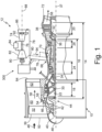
- FIG. 1 is a schematic representation of gas turbine engine 10 that includes boost spool 12 in accordance with an exemplary embodiment of this disclosure.
- Gas turbine engine 10 is a dual spool engine that includes low pressure spool 14 and high pressure spool 16.
- Low pressure spool 14 includes low pressure compressor 18 mechanically and rotationally connected to low pressure turbine 20 by shaft 22, and high pressure spool 16 includes high pressure compressor 24 mechanically and rotationally connected to high pressure turbine 26 by shaft 28.
- Bearings 30 and 32 support shaft 22 of low pressure spool 14, and bearings 34 and 36 support shaft 28 of high pressure spool 16, each at forward and aft shaft ends, respectively.
- Low pressure spool 14 and high pressure spool 16 are coaxial, each extending along and rotating about centerline 37 independently of one another.
- Compressors and turbines 18, 20, 24, and 26 include at least one compressor stage or turbine stage, each stage formed by a row of stationary vanes and a row of rotating blades.
- each of low pressure compressor 18 and high pressure compressor 24 has three stages
- each of low pressure turbine 20 and high pressure turbine 26 has two stages, although the number of stages in each compressor or turbine can be selected based on the desired pressure ratios as is known in the art.
- boost spool 12, low pressure spool 14, and high pressure spool 16 may be referred to as a first spool, a second spool, and/or a third spool in which "first”, “second”, and “third” correspond to one of boost spool 12, low pressure spool 14, and high pressure spool 16.
- first”, “second”, and/or “third” labels may be used in conjunction with corresponding components of the first spool, the second spool, and/or the third spool in order to distinguish components of each spool from components of the other spools.
- variable area turbine 38 includes a row of vanes, each vane rotatable about a vane axis extending in a spanwise direction of the vane.
- the open area through variable area turbine (VAT) 38 changes depending on the stagger angle of vanes with respect to centerline 37.
- the closed position occurs when vanes form a maximum stagger angle with respect to centerline 37 while the open position occurs when vanes form a minimum, and sometimes negative, stagger angle with respect to centerline 37.
- the minimum open area typically coincides with the closed position since vanes tend to rotate toward each other, and in some instances vanes overlap when viewed along centerline 37.
- vanes As vanes move from the closed position towards the open position, the open area through the vane stage increases until a maximum open area is reached, typically near a minimum turning angle, or zero stagger angle position. In some embodiments, the open position coincides with the vane position associated with a maximum open area through the vane row. In other embodiments, vanes can continue to rotate towards the open position in which the vane stagger angle is negative, tending to decrease the open area as the stagger angle becomes more negative.
- a neutral position or nominal position of vanes can be associated with an angular vane position between the open position and the closed position that achieve a desired incident angle with a rotor of low pressure turbine 20.
- Gas turbine engine 10 also includes fan 39 mounted to fan shaft 40.
- One or more bearings 42 support fan shaft 40, which is mechanically and rotationally coupled to low pressure spool 14.
- Fan shaft 40 may be directly connected to shaft 22 of low pressure spool 14. With this arrangement, fan 39 and fan shaft 40 rotate at the same speed and in the same direction as low pressure spool 14. In other embodiments, such as the exemplary embodiment depicted in FIG. 1 , fan shaft 40 may be rotationally coupled to shaft 22 via gearing 44.
- gearing 44 can be an epicyclic gear train that includes a central sun gear mounted to shaft 22, a ring gear mounted to fan shaft 40, and a plurality of planet gears circumferentially spaced about the sun gear and mechanically engaging the ring gear and the sun gear, the planet gears being supported by a planet carrier (not shown).
- gas turbine engines utilizing epicyclic gearing to drive fan 39 and fan shaft 40 restrain the planet carrier to cause fan shaft 40 to rotate slower (and in the opposite direction) than low pressure spool 14. Accordingly, fan 39 and low pressure spool 14 can rotate at speeds that are more efficient for respective blade geometries.
- nose cone 46 guides ambient air flow 48 into inlet 50.
- Rotation of fan 39 which includes circumferentially spaced fan blades 52, compresses ambient air flow 48 before splitter 54 divides flow 48 into bypass flow 56 and core flow 58.
- Bypass flow 56 passes through bypass duct 60 to structural guide vanes 62 and discharges from engine 10 through a bypass flow exhaust nozzle (not shown), which is downstream from structural guide vane outlet 64.
- Inlet guide vanes 66 guide core flow 58 into low pressure compressor 18 that subsequently flows into high pressure compressor 24, each compressor stage further compressing core flow 58.
- Compressed core flow 58 discharges from high pressure compressor 24 into diffuser 68.
- Diffuser 68 fluidly connects high pressure compressor 24 to combustor 70 and includes divergent walls that reduce core flow 58 velocity and thereby increase static pressure of flow 58 before entering combustor 70.
- Combustor 70 can be an annular combustor (or another suitable design). Fuel injected into combustor 70 mixes with compressed core flow 58, and one or more ignitors combust the fuel-to-air mixture to produce a compressed and heated core flow 58 that is discharged into high pressure turbine 26. Core flow 58 interacts with vanes and blades of high pressure turbine 26 causing rotation of shaft 28 about centerline 37 and driving rotation of high pressure compressor 24.
- core flow 58 interacting with vanes and blades of low pressure turbine 20 cause rotation of shaft 22 about centerline 37 to drive rotation of low pressure compressor 18 as well as fan shaft 40 directly or via gearing 44. Downstream of low pressure turbine 20, core flow 58 discharges from engine 10 through exhaust nozzle 72.
- Boost spool 12 includes at least boost compressor 74 and shaft 76 fluidly connected to gas turbine engine 10 by inlet duct assembly 78 and outlet duct assembly 80.
- boost spool 12 also includes one or more of boost turbine 82, combustor 84, and variable inlet guide vanes 86.
- Boost compressor 74 and boost turbine 82 include at least one compressor stage or turbine stage, each stage formed by a row of stationary vanes and a row of rotating blades.
- Variable inlet vanes 86 form an array of circumferentially spaced vanes at an inlet to boost spool 12 and upstream of boost compressor 74.
- Each vane of variable inlet guide vanes 86 is rotatable about a vane axis that extends in a spanwise direction of the vane.
- An angular position of variable inlet guide vanes 86 ranges between a closed position, a neutral or nominal position, and an open position in the same manner as vanes of variable area turbine 38.
- variable inlet vanes 86 can pivot to decrease or increase the open inlet area in order to vary the amount of core flow 58 diverted into boost compressor 74 through inlet duct assembly 78.
- Shaft 76 mechanically and rotationally connects boost compressor 74 to boost turbine 82, each component arranged coaxially with boost axis 88.
- Bearings 90 and 92 support boost spool 12 with respect to a stationary casing, which may be affixed or incorporated to a casing of gas turbine engine 10.
- Transmission 300 mechanically and rotationally couples boost spool 12 to one or more spools of gas turbine engine 10 (e.g., low pressure spool 14 and/or high pressure spool 16) as discussed further below.
- boost axis 88 can be parallel and offset from centerline 37 of gas turbine engine 10 as schematically shown by FIG. 1 .
- FIG. 1 shows boost spool 12 with a reverse flow orientation (i.e., aft-to-forward flow) such that a flow direction through boost spool 12 from compressor 74 to turbine 82 is opposite a flow direction (i.e., forward-to-aft flow) through gas turbine engine 10 from inlet 50 to outlet 64 and from inlet 50 to nozzle 72.
- boost axis 88 can be oblique or perpendicular to centerline 37.
- boost spool 12 For all mounting positions of boost spool 12, the location and orientation of boost spool 12 permits boost spool 12 to receive a compressed air flow from gas turbine engine 10 and to discharge an expanded air flow to gas turbine engine 10.
- Boost spool 12 can receive a compressed airflow from any compressor stage of gas turbine engine 10 to achieve varying degrees of boost compression.
- boost spool 12 receives a compressed air flow from a location that is downstream from the last compressor stage of the gas turbine engine.
- boost spool 12 receives airflow from diffuser 68 and discharges an expanded airflow to diffuser 68.
- boost spool receives airflow from diffuser 68 and discharges an expanded airfoil to both diffuser 68 and combustor 70, which is downstream of high pressure compressor 24 and upstream from high pressure turbine 26.
- boost spool 12 receives a portion of core flow 58 extracted from diffuser 68 (i.e., boost flow 94) and routed to an inlet of boost compressor 74 through inlet duct assembly 78.
- boost flow 94 Within boost compressor 74, the pressure and temperature of boost flow increases with each compressor stage.
- Compressed boost flow 94 enters combustor 84 where injected fuel mixes with compressed boost flow 94. Once the fuel-air mixture is ignited, boost flow 94 discharges into boost turbine 82.
- Turbine 82 expands boost flow 94 across each turbine stage, driving turbine 82, shaft 76, and compressor 74. Expanded boost flow 94 discharges from boost spool 12 through outlet duct assembly 80, which may route discharged air to diffuser 68, combustor 70, or both diffuser 68 and combustor 70.
- FIG. 2 schematically depicts inlet duct assembly 78 that extracts a portion of core flow 58 from diffuser 68 and outlet duct assembly 80 that discharges the boost flow to diffuser 68 and combustor 70.
- diffuser 68 includes inner peripheral wall 96 and outer peripheral wall 98 spaced radially outward from wall 96.
- Multiple struts 100 extend from inner peripheral wall 96 to outer peripheral wall 98 of diffuser.
- FIG. 2 depicts five struts 100. However more or less struts 100 can be used in other examples, each incorporating features of inlet duct assembly 78 and outlet duct assembly 80 discussed below.
- Combustor 70 includes outer casing 102 and spaced radially from inner casing 104 to define an annular combustion chamber. Inner casing 104 and outer casing 102 are thermally protected by segmented liners 106.
- inlet duct assembly 78 includes multiple branch ducts 108 collected into inlet manifold 110. Each branch duct 108 communicates with diffuser 68 via respective branch inlets 112.
- branch inlets 112 can be formed by inner and/or outer peripheral walls of diffuser 68 such that branch ducts 108 extract core flow 58 through inner and outer walls of diffuser 68.
- branch inlets 112 are formed by respective struts 100.
- Branch inlet ducts 108 extend from branch inlets 112 to inlet manifold 110.
- Inlet manifold 110 can be a pipe, duct, or plenum accommodating the collected flow through each branch inlet duct 108 and routing the accumulated inlet flow to inlet of boost spool 12.
- outlet duct assembly 80 can include one or more ducts extending from an outlet of boost turbine 82 to diffuser 68, combustor 70, or both diffuser 68 and combustor 70.
- outlet duct assembly 80 can include main duct 114 extending from an outlet of boost turbine 82 to one or more branch outlet ducts 116, one or more branch outlet ducts 116, or one or more branch outlet ducts 116 and one or more branch outlet ducts 118.
- Each branch outlet duct 116 extends from main duct 114 to one of boost outlets 120 formed in an inner peripheral wall or an outer peripheral wall of diffuser 68, or a wall of strut 104, placing main duct 114 and boost turbine 82 in communication with diffuser 68.
- Each branch outlet duct 118 extends from main duct 114 to one of boost outlets 122 formed in a peripheral wall of combustor 70, placing main duct 114 and boost turbine 82 in communication with combustor 70.
- outlet duct assembly 80 includes main duct 114, multiple branch ducts 116, and branch duct 118.
- Main duct 114 extends from boost turbine 82 to each branch outlet duct 116 and branch duct 118.
- Branch outlet ducts 116 extend from main duct 114 to boost outlets 120 formed in walls of respective struts 100.
- Branch outlet duct 118 extends from main duct 114 to boost outlet 122 formed in a peripheral wall bounding a combustion zone of combustor 70.
- FIG. 3 is a schematic of diffuser 68 and combustor 70 of gas turbine engine 10.
- branch inlet duct 108 extracts air from core flow 58 through inlet 112, and branch duct 116 discharges boost exhaust flow through outlet 120.
- Branch inlets 112 and branch outlets 120 are formed by strut 100.
- One or both of branch inlet 112 and branch outlet 120 can extend from inner peripheral wall 96 to outer peripheral wall 98.
- Outlet 122 of branch outlet duct 118 discharges through outer casing of combustor 70. The location of outlet 122 is spaced axially downstream from injectors 124, or between injectors 124 and high pressure turbine 26.
- FIG. 4 depicts another schematic view of struts 100 and the flow distribution within diffuser 68.
- Each strut 100 includes first side wall 126 and second side wall 128 extending from leading edge 130 of strut 100 to rear wall 132.
- Inlets 112 are disposed in one of sidewalls 126 and 128 while outlets 120 are disposed in the other sidewall opposite the inlet sidewall.
- boost spool 12 a portion of compressed core flow 58 enters each inlet 112 and flows through branch inlet ducts 108 and manifold 12to the inlet of boost spool 12 and boost compressor 74.
- a portion of boost spool flow exiting boost turbine 82 flows through each branch outlet duct 116 before discharging through each outlet 120 into diffuser 68.
- An outlet flow division can be achieved with appropriate selection of length, cross-sectional area, and routing of main duct 114, diffuser branch ducts 116, combustor branch duct 118 and associated outlets 120 and 122 of outlet duct assembly 80.
- a minimum mass flow rate of boost exhaust discharged to diffuser through outlets 120 relates to an amount of flow required to maintain flow into boost spool 12 through inlet duct assembly 78.
- Adequate flow through inlet duct assembly 78 can be achieved by maintaining at least a minimum static pressure at branch inlets 112 throughout all operating conditions during which boost spool 12 can be operated, including transient periods associated with starting or stopping boost spool 12.
- the maximum mass flow rate of boost exhaust discharged to diffuser 68 through outlets 120 relates to a maximum temperature of fuel injectors within combustor 70.
- boost exhaust mass flow rate increases, a temperature of compressed air entering combustor 70 increases. Accordingly, the maximum permitted temperatures of components of combustor 70 during continuous operation limits the maximum mas flow rate of boost exhaust returned to diffuser 68 through outlets 120.
- five percent to forty percent of boost exhaust flow can be discharged into diffuser 68 while the remainder ninety-five percent to sixty percent of boost exhaust flow can be discharged to combustor 70.
- boost exhaust between diffuser 68 and combustor 70 allows boost outlets 120 to extend from the inner peripheral wall to the outer peripheral wall of diffuser 68 as shown in FIG. 3 .
- boost outlets 120 As the radial extent of boost outlets 120 approaches the full radial extent of diffuser 68 at struts 100, flow uniformity and flow stability increase within diffuser 68 while component temperatures within combustor 70 remain acceptable for continuous operation.
- FIG. 5 is a T-s diagram illustrating the thermodynamic performance of gas turbine engine 10 boosted by spool 12 relative to gas turbine engine 10 operating without boost spool 12. Entropy is displayed along abscissa axis 134, and temperature is displayed along ordinate axis 136, each increasing from origin 138. Dashed curve A depicts the preferred thermodynamic cycle of gas turbine engine 10 operating without boost engaged at takeoff power. Dashed curve B depicts the thermodynamic cycle of gas turbine engine 10 were boost to be engaged while operating at takeoff power on a hot day. Solid curve C depicts gas turbine engine 10 operating without boost spool 12 engaged while operating at cruise power.
- Solid curves C and D are defined by points 2C, 3C, 4C, and 5C and points 2D, 3D, 4D, and 5D in a similar manner to curves A and B.
- An engine operating along curve A has less OPR (value Y) than an engine operating on any of the other curves (i.e., curves C and D having an OPR equal to value X and curve B having an OPR value equal to Z).
- an engine operating on curves C and D have an OPR value X that is greater than an engine operating on curve B with an OPR value Z.
- the temperature entering the compressor section of gas turbine engine 10 at cruise power is lower than the temperature entering the compressor section of gas turbine engine 10 at takeoff power because the ambient temperature at cruising altitude is lower than the ambient temperature during a hot day takeoff.
- the ambient temperature can be approximately -26.1 degrees Celsius (or about -15 degrees Fahrenheit) while on a hot day takeoff, the ambient temperature can be approximately 46.1 degrees Celsius (or about 115 degrees Fahrenheit).
- the temperature within the engine at points 3A, 3B, 3C, and 3D are limited to a line of constant temperature labeled "T3 Limit" while the temperature at points 4A, 4B, 4C, and 4D are limited to a line of constant temperature labeled "T4 Limit".
- Unboosted operation of gas turbine engine 10 represented by dashed curve A trades engine fuel efficiency and engine materials life between temperature limits during a hot day takeoff and cruising. As a result, the OPR of unboosted operation of engine 10 is reduced by hot day takeoff conditions (i.e., the temperature at point 4A is lower than the temperature at 4B).
- the area bounded by dashed curve A and a line connecting points 5A and 2A represent the amount of work completed by engine 10 while operating at takeoff power and without boost spool 12 operation.
- the area bounded by dashed curve B and a line connecting points 5B and 2B represent the amount of work completed by engine 10 while operating at takeoff power and with boost spool 12 operation.
- the two areas are the same and the amounts of work completed by the engine at takeoff are the same.
- the amount of heat energy rejected by gas turbine engine 10 while operating in accordance with dashed curve A is shown by horizontally-hatched area 140.
- the thermodynamic efficiency of gas turbine engine 10 operating in accordance with dashed curve A is the work energy divided by the summation of work and rejected heat energy defined by curve A.
- gas turbine engine 10 with the same OPR as boost engine operation depicted by curve D does not have the improved engine fuel efficiency and same life of operation.
- the temperature at 4B is higher than the temperature 4A.
- gas turbine engine 10 can be operated without boost spool 12 during hot day takeoff conditions (i.e., dashed curve A) and can be operated with boost spool 12 at cruise power (i.e., solid curve D) to achieve greater thermal efficiency at cruise power while satisfying thermal limits for hot day takeoff conditions.
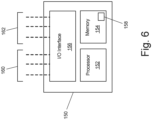
- FIG. 6 is a schematic of controller 150 that regulates the operation of gas turbine engine 10 and, more particularly, coupling and decoupling of boost spool 12 via one of transmission 300. Additionally, controller 150 regulates fuel flow rates to primary combustor 70 and secondary combustor 84 based on one or more engine parameters, aircraft parameters, and/or exterior conditions. Controller 150 can include a standalone control unit or a control module incorporated into another control unit. Furthermore, controller 150 can be an amalgamation of distinct control units and/or distinct control modules that together perform the functions described in this disclosure. In some embodiments, controller 150 can be a full authority digital engine control (FADEC), an electric engine controller (EEC), or an engine control unit (ECU).
- FADEC full authority digital engine control
- EEC electric engine controller
- ECU engine control unit
- Controller 150 includes processor 152, memory 154, and input/output interface 156.
- Processor 152 executes one or more control algorithms 158 stored within memory 154 to output engine control signals 160 based on one or more input signals 162.
- Examples of processor 152 can include any one or more of a microprocessor, a controller, a digital signal processor (DSP), an application specific integrated circuit (ASIC), a field-programmable gate array (FPGA), or other equivalent discrete or integrated logic circuitry.
- DSP digital signal processor
- ASIC application specific integrated circuit
- FPGA field-programmable gate array
- Memory 154 can be configured to store information within controller 154.
- Memory 154 in some examples, is described as computer-readable storage media.
- a computer-readable storage medium can include a non-transitory medium.
- the term "non-transitory" can indicate that the storage medium is not embodied in a carrier wave or a propagated signal.
- a non-transitory storage medium can store data that can, over time, change (e.g., in RAM or cache).
- Memory 154 can include volatile and non-volatile computer-readable memories. Examples of volatile memories can include random access memories (RAM), dynamic random-access memories (DRAM), static random-access memories (SRAM), and other forms of volatile memories. Examples of non-volatile memories can include, e.g., magnetic hard discs, optical discs, flash memories, or forms of electrically programmable memories (EPROM) or electrically erasable and programmable (EEPROM) memories.
- RAM random access memories
- DRAM dynamic random-access memories
- SRAM static
- I/O interface 156 can be a series of input and output channels that electrically communicate with an engine control bus.
- the engine control bus interconnects controller 150 with various components of the gas turbine engine 10 described above such that engine control signals 160 can be transmitted to individual engine components and input signals 162 can be received.
- Engine control signals 160, input signals 162, or both engine control signals 160 and input signals 162 can be an analog signal or a digital signal.
- an analog signal can be a voltage that varies between a low voltage to a high voltage whereas digital signals can be a series of discrete voltage states distributed over a voltage range.
- engine control signals 160 cause various components of gas turbine engine 10 to change state or position.
- engine control signals 160 can be used to vary the position of one or more fuel valves to vary the fuel rate entering a combustor.
- Other examples of engine control signals 160 include signals associated with engagement or disengagement of clutches and an angular position of variable vane stages.
- Input signals 162 are representative of one of engine parameters, aircraft parameters, and environmental parameters.
- Exemplary engine parameters include rotational speed of a low pressure spool, high pressure spool, boost spool, and/or fan shaft, the state or position of fuel valves, bleed valves, the state or position of clutch assemblies, the temperature or pressure within the compressor, combustor, or turbine, and engine power.
- Aircraft parameters include various parameters associated with an aircraft such as power lever angle, altitude, pitch angle, yaw angle, roll angle, rate of climb, and airspeed, among other possible parameters.
- Exterior parameters include ambient temperature and pressure at the inlet of gas turbine engine 10.
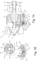
- FIG. 7A and FIG. 7B are schematic views depicting an exemplary embodiment of gas turbine engine 10 that includes transmission 300 for driving boost spool 12 and accessory gearing 302.
- Transmission 300 includes drive gear 304, input gear 306, tower shaft 308, output gear 310, differential input gear 312, shaft 314, sun gear 316, planet gears 318, planet carrier 320, ring gear 322, shaft 324, locking element 326, and clutch 328.
- transmission 300 forms a biased, locking differential gearbox in which low pressure shaft 22 and boost shaft 76 are inputs and accessory gearing 302 is the output.
- Low pressure spool 14 is rotationally coupled to sun gear 316 to provide a first input to the biased, locking differential gearbox.
- Drive gear 304 mounts to shaft 22 of low pressure spool 14.
- Tower shaft 308 extends radially outward from shaft 22 of low pressure spool 14 towards boost spool 12.
- At an interior or radially inner end tower shaft 308 includes input gear 306 enmeshed with drive gear 304.
- tower shaft 308 includes output gear 310 enmeshed with differential input gear 312.
- Differential input gear 312 is mounted on shaft 314, which extends from differential input gear 312 to sun gear 316.
- Sun gear 316 is mounted to, or otherwise rotationally coupled to shaft 314. Accordingly, shaft 22 of low pressure spool 14 is rotationally coupled to sun gear 316 via tower shaft 308 and shaft 314 and associated gearing.
- Boost spool 12 is rotationally coupled to planet carrier 320 to provide a second input of the biased, locking differential gearbox.
- Planet carrier 320 is mounted to shaft 76 of boost spool 12 such that shaft 76 and planet carrier 320 rotate at the same speed and in the same direction.
- Planet carrier 320 includes multiple bearing journals equally-spaced circumferentially about a rotational axis of planet carrier 320.
- Planet gears 318 are supported from respective bearing journals.
- Clutch 328 is disposed between shaft 76 of boost spool 12 and planet carrier 320 of transmission 300.
- boost spool 12 and planet carrier 320 rotate at the same speed and in the same direction about boost axis 88.
- boost spool 12 and planet carrier 320 are rotationally uncoupled such that boost spool 12 and planet carrier 320 rotate independently.
- Accessory gearing 302 is rotationally coupled to ring gear 322 to provide an output of the biased, locking differential gearbox.
- Accessory gearing 302 includes one or more gears enclosed within housing 330 of accessory gearbox 332. Housing 330 subtends a sector about casing 334 of engine 10.
- One or more gears of accessory gearing 302 are driven by ring gear 322 directly or a shaft and output gear joined to ring gear 322. At least some of the gears of accessory gearing 302 are rotationally coupled to respective output shafts 336.
- Each output shaft 336 drives an engine accessory (e.g., a fuel pump, generators, constant speed drives, lubricating oil pumps, hydraulic pumps, and engine starters).
- engine accessory e.g., a fuel pump, generators, constant speed drives, lubricating oil pumps, hydraulic pumps, and engine starters.
- Locking element 326 translates between an engaged state and a disengaged state.
- locking element 326 rotationally couples planet carrier 320 to ring gear 322 or to sun gear 316 such that planet carrier 320, sun gear 316, and ring gear 322 rotate at a common speed.
- locking element 326 rotationally uncouples planet carrier 320 from ring gear 322 or sun gear 316 such that planet carrier 320, ring gear 322, and sun gear 316 may rotate relative to each other.
- engaging locking element 326 increases the percentage of power transferred to low pressure spool 14 from boost spool 12 relative to the disengaged position of locking element 326.
- boost spool 12 splits between low pressure spool 14 and accessory gearing 302.
- boost spool 12 in concert with gas turbine engine 10 and transmission 300 depends on the operational range of gas turbine engine 10 input by power lever angle (PLA).
- the power lever angle (PLA) varies between zero percent (i.e., PLA 0) and one hundred percent (i.e., PLA 100).
- a power lever angle (PLA) equal to zero corresponds with an engine shutdown condition whereby fuel flow to combustor 70 stops and any remainder fuel is burned off or returned to fuel tanks of the aircraft.
- intermediate power lever angles include engine start, ground idle and/or flight idle, a reduced cruising power level associated with loiter, cruise, and climb.
- a power lever angle (PLA) equal to one hundred percent corresponds to takeoff power.
- power lever angle (PLA) values can be engine and/or aircraft dependent
- controller 150 Based on power lever angle (PLA) and one or more additional engine parameters, aircraft parameters, and/or external parameters, controller 150 transmits control signals to components of transmission 300 as well as fuel system components regulating fuel flows to combustor 70 (i.e., a primary combustor) and combustor 84 (i.e., a secondary combustor) to operate gas turbine engine 10 as described in the following scenarios.
- PPA power lever angle
- gas turbine engine 10 includes a minimum continuous power level and a maximum continuous power level.
- the minimum continuous power level and the maximum continuous power level correspond to the minimum and maximum power levels at which gas turbine engine 10 can operate continuously and in which pressure and temperature at various locations within the engine stabilize.
- the minimum continuous power level can correspond to the ground idle condition while the maximum continuous power level can correspond to the takeoff conditions.
- Boost spool 12 operates within an intermediate power range of gas turbine engine 10.
- the intermediate power range is a subset of sequential power levels of gas turbine engine 10 bound by a minimum power level and a maximum power level.
- the minimum power level of intermediate power range may coincide with power lever angles (PLA) corresponding to engine start, ground idle, flight idle, loiter, cruise, or a power level between engine start and cruise.
- the maximum power level of intermediate power range may coincide with power lever angles (PLA) corresponding to cruise, climb, takeoff, or a power level condition between cruise and takeoff power.
- the intermediate power range can be further divided into two or more power subranges. For instance, sequentially continuous low power subrange and high power subrange can define the intermediate power range.
- the low power subrange extends from the minimum power level of intermediate power range to an intermediate power level greater than the minimum power level and less than the maximum power level of intermediate power range.
- the high power subrange extends from the intermediate power level to the maximum power level of the intermediate power range.
- Table 1 describes the operational range of gas turbine engine 10 equipped with transmission 300.
- the intermediate power range extends that include the cruise condition and includes at least two power subranges.
- High power subrange extends from the loiter condition to the cruise condition.
- controller 150 varies a fuel flow rate delivered to secondary combustor 84 based on rotational speed of accessory gearbox 332 (NAGB).
- NAGB accessory gearbox 332
- clutch 328 is engaged to rotationally couple boost shaft 76 to planet carrier 320.
- Locking member 326 is disengaged allowing planet carrier 320 to rotate relative to sun gear 316 and ring gear 322.
- controller 150 increases the open area through the variable area turbine (VAT) 38 by commanding variable area turbine 38 to an open position or towards the open position.
- VAT variable area turbine
- Low power operation spans from ground idle power (PLA ⁇ 10) to loiter power (PLA ⁇ 40).
- controller 150 regulates a fuel flow rate delivered to primary combustor 70 based on the power lever angle (PLA) and, contemporaneously, regulating a fuel flow rate delivered to secondary combustor 84 based on the speed of accessory gearbox 332. While clutch 328 remains engaged and locking member 326 remains disengaged, variable turbine vanes are moved to or towards a nominal position, decreasing an open area through variable turbine vanes.
- locking member 326 When the power level corresponds to loiter power or a lesser power level, locking member 326 disengages, allowing planet carrier 320, ring gear 322, and sun gear 316 to rotate at different speeds. As the power lever angle (PLA) exceeds loiter power, controller 150 moves locking element 326 to the engaged position, rotationally coupling planet carrier 320 to ring gear 322 or to sun gear 316, tying the gears to a common speed.
- PPA power lever angle
- controller 150 varies a fuel flow rate delivered to primary combustor 70 based the minimum engine pressure ratio (EPRmin) and simultaneously varies a fuel flow rate delivered to secondary combustor 84 based on a position of the power lever (PLA) or a requested power level.
- EPRmin engine pressure ratio
- VAT variable area turbine
- controller 150 disengages clutch 328 uncoupling boost spool 12 from low pressure spool 14 and stops fuel flowing to secondary combustor 84.
- the fuel flow rate delivered to primary combustor 70 is regulated by controller 150 based on the power lever angle (PLA) or requested power level.
- PPA power lever angle
- VAT variable area turbine
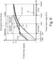
- FIG. 8 depicts an exemplary speed profile of gas turbine engine 10 equipped with transmission 300.
- rotational speeds of high pressure spool 16 (NHP), low pressure spool 14 (NLP), boost spool 12 (NB), and the input of accessory gearbox 332 (NAGB) are expressed as a percentage of respective maximum operational speeds of each spool or component.
- Dashed lines indicate starting, shutdown, or unpowered operation such as when a spool or component freewheels.
- Solid lines indicate operation of gas turbine engine 10 while delivering fuel to primary combustor 70, secondary combustor 84, or both primary and secondary combustors.
- the fuel flow rate delivered to combustor 84 within the low power subrange varies such that the differential output between the low pressure spool input and the boost spool input produces a constant speed, or minimal speed variation, at ring gear 322. Accordingly, engine accessories driven by accessory gearing via ring gear 322 are not required to accommodate larger operating speed ranges.
- the gear ratios between boost spool 12 and low pressure spool 14 is selected such that boost spool 12 attains its maximum operating speed when low pressure spool 14 attains approximately eighty percent to ninety percent of its maximum operating speed. Furthermore, the maximum operating speed of boost spool 12 coincides with the cruise condition and thereby provides increases the maximum overall pressure ratio (OPR) of gas turbine engine 10 during the longest phases of flight.
- boost spool 12 can be uncoupled from low pressure spool and accessory gearbox 332 by disengaged clutch 328.
- preventing rotation of planet carrier 320 by engaging locking element 326 converts ring gear 322, planet carrier 320, and sun gear 316 into a fixed speed ratio between low pressure spool 14 and accessory gearing 302. Accordingly, engine accessories are driven at a fixed speed ratio relative to low pressure spool 14 from cruise power to takeoff power.
- a gas turbine engine includes a first spool, a second spool, a third spool, a plurality of engine accessories, and an accessory gearbox.
- the first spool includes a first compressor and a first turbine mounted to a first shaft.
- the second spool includes a second compressor and a second turbine mounted to a second shaft.
- the third spool includes a third compressor and a third turbine mounted to a third shaft.
- the accessory gearbox includes a housing, a sun gear, a ring gear, and a plurality of planet gears.
- the sun gear rotationally couples to the third shaft.
- the ring gear rotationally couples to the plurality of engine accessories.
- the plurality of planet gears enmesh with the sun gear and the ring gear.
- a carrier supports the plurality of planet gears and is rotationally coupled to the second shaft.
- the gas turbine engine of the preceding paragraph can optionally include, additionally and/or alternatively, any one or more of the following features, configurations and/or additional components.
- a further embodiment of the foregoing gas turbine engine wherein the carrier can be rotationally coupled to the sun gear or the ring gear in the engaged position of the locking member to thereby prevent rotation of the carrier with respect to the sun gear and the ring gear.
- a further embodiment of the foregoing gas turbine engine can include a variable area turbine disposed between the first turbine and the third turbine or in the third turbine.
- vanes of the variable area turbine are rotatable about respective pivot axes to vary an open area of the variable area turbine.
- a further embodiment of the foregoing gas turbine engine can include a tower shaft rotationally coupling the sun gear to the third shaft.
- a further embodiment of the foregoing gas turbine engine wherein a rotational axis of the second shaft can be offset and parallel to a rotational axis of the first shaft and a rotational axis of the third shaft.
- a further embodiment of the foregoing gas turbine engine wherein the first shaft can be concentric to the third shaft.
- a further embodiment of the foregoing gas turbine engine wherein the first compressor can be a high pressure compressor and the third compressor can e a low pressure compressor.
- a further embodiment of the foregoing gas turbine engine wherein the first turbine can be a high pressure turbine and the third turbine can be a low pressure turbine.
- a further embodiment of the foregoing gas turbine engine, wherein a second maximum speed can be the maximum continuous rotational speed of the second spool.
- a further embodiment of the foregoing gas turbine engine, wherein the third maximum speed can be the maximum continuous rotational speed of the third spool.
- a further embodiment of the foregoing gas turbine engine wherein a gear ratio of between the second spool and the third spool rotates the second spool at the second maximum speed when a third rotational speed of the third spool is equal to or less than 90% of the third maximum speed and greater than or equal to 80% of the third maximum speed.
- a further embodiment of the foregoing gas turbine engine can include a clutch disposed between the planet carrier and the second shaft.
- a further embodiment of the foregoing gas turbine engine, wherein the clutch can include an engaged state whereby the second shaft is coupled to the planet carrier.
- a further embodiment of the foregoing gas turbine engine wherein the housing of the accessory gearbox can subtend the gas turbine engine about the first spool and the third spool.
- a further embodiment of the foregoing gas turbine engine wherein the third shaft can be concentric with the first shaft.
- a further embodiment of the foregoing gas turbine engine wherein the second shaft can be offset from the first shaft and the third shaft.
- a further embodiment of the foregoing gas turbine engine can include a primary combustor communicating with the first compressor and the first turbine.
- a further embodiment of the foregoing gas turbine engine can include a secondary combustor communicating with the second compressor and the second turbine.
- a further embodiment of the foregoing gas turbine engine wherein a primary flow path includes, in flow series, the third compressor, the first compressor, the primary combustor, the first turbine, and the second turbine.
- a further embodiment of the foregoing gas turbine engine wherein a secondary flow path includes, in flow series, the second compressor, the second combustor, and the second turbine.
- a further embodiment of the foregoing gas turbine engine wherein the secondary flow path can intersect the primary flow path between the first compressor and the primary combustor.
- a further embodiment of the foregoing gas turbine engine wherein the first compressor can be a high pressure compressor and the second compressor can be a low pressure compressor.
- a further embodiment of the foregoing gas turbine engine wherein the first turbine can be a high pressure compressor and the second turbine can be a low pressure compressor.
- a method of operating a gas turbine engine includes supplying a first fuel flow rate to a primary combustor of the gas turbine engine contemporaneously with supplying a second fuel flow rate to a secondary combustor of the gas turbine engine based on a power lever angle indicative of a first power subrange of an intermediate power range.
- the intermediate power range consisting of the first power subrange and a second power subrange in which the intermediate power range is between a maximum continuous power and a minimum continuous power associated with an operational range of the gas turbine engine.
- the method of the preceding paragraph can optionally include, additionally and/or alternatively, any one or more of the following features, configurations, additional components and/or steps.
- a further embodiment of the forgoing method wherein the first fuel rate can vary based on the power lever angle and the second fuel flow rate can vary based on a rotational speed of an accessory gearbox.
- a further embodiment of any of the foregoing methods can include engaging a locking member to rotationally couple a planet carrier to a ring gear or a sun gear of an epicyclic differential based on a power lever angle greater than the first power subrange.
- a further embodiment of any of the foregoing methods can include supplying a third fuel flow rate to the primary combustor of the gas turbine engine contemporaneously with supplying a fourth fuel flow rate to the secondary combustor of the gas turbine engine based on the power lever angle indicative of the second power subrange of the intermediate power range.
- a further embodiment of any of the foregoing methods can include disengaging a clutch based on the power lever angle greater than the second subrange and less than or equal to the maximum continuous power.
- a further embodiment of any of the foregoing methods can include supplying the first fuel flow rate to the primary combustor of the gas turbine engine contemporaneously with stopping fuel flow to the secondary combustor based on the power lever angle greater than the second subrange and less than or equal to the maximum continuous power.
- a further embodiment of any of the foregoing methods can include supplying the second fuel flow rate to the secondary combustor contemporaneously with supplying the third fuel flow rate to the primary combustor based on the power lever angle less indicative of a power level less than the first sub range and greater than or equal to the minimum continuous power.
- a further embodiment of any of the foregoing methods can include disengaging the locking member to rotationally uncouple the planet carrier from the ring gear and the sun gear of the epicyclic differential based on the power lever angle less than the second power subrange.
- a further embodiment of any of the foregoing methods, wherein rotationally uncoupling the planet carrier from the ring gear or the sun gear can permit rotation of the planet carrier relative to the ring gear and the sun gear.
Landscapes
- Engineering & Computer Science (AREA)
- Chemical & Material Sciences (AREA)
- Combustion & Propulsion (AREA)
- Mechanical Engineering (AREA)
- General Engineering & Computer Science (AREA)
- Control Of Turbines (AREA)
- Retarders (AREA)
Abstract
Description
- The present disclosure relates generally to gas turbine engines and, more particularly, to gas turbine engines capable of operating in a high overall pressure ratio (OPR) mode and in a low OPR mode to adapt to the ambient conditions and to provide more efficient operation without exceeding thermal limits of the gas turbine engine.
- The overall pressure ratio (OPR) is a measure of the total pressure rise in a gas turbine engine (i.e., a pressure ratio equal to the air pressure discharged from the last compressor stage to the ambient air pressure entering the engine). Generally speaking, as OPR increases, the thermodynamic efficiency of the gas turbine engine increases, enabling the engine to consume less fuel per unit of thrust (i.e., thrust specific fuel consumption or TSFC) than a corresponding engine with lower OPR. However, air temperatures within the gas turbine engine increase with increasing OPR and can produce temperatures within the compressor section and/or turbine section that exceed permissible material and structural limits. Furthermore, the maximum temperature within the compressor and the turbine increase as the ambient temperature increases, adding to the temperature increase associated with the OPR of the engine.
- Conventionally, turbine temperatures are maintained within acceptable limits by limiting OPR to a ratio that produces acceptable turbine temperatures for worst case ambient conditions, typically, design conditions corresponding to hot day take-off. While this technique produces a gas turbine engine design that provides an acceptable compromise for a variety of operating conditions, limiting OPR for hot day take-off conditions produces a gas turbine engine that operates at less OPR than otherwise possible at cruise power, reducing engine efficiency when high efficiency, low fuel consumption operation is most advantageous to extend aircraft range or payload capacity.
- A gas turbine engine in accordance with a first aspect of the invention includes a first spool, a second spool, a third spool, an accessory gearbox, and a plurality of engine accessories. The first spool includes a first compressor and a first turbine mounted to a first shaft. The second spool includes a second compressor and a second turbine mounted to a second shaft. The third spool includes a third compressor and a third turbine mounted to a third shaft. The accessory gearbox includes a locking epicyclic differential. The epicyclic differential includes a sun gear, planet gears supported by a carrier, and ring gear. The second shaft couples to the planet carrier, and the third shaft couples to the sun gear. Engine accessories couple to the ring gear. The locking member selectively couples the carrier to the ring gear or to the sun gear, thereby preventing rotation of the planet carrier relative to the ring gear or the sun gear.
- A further embodiment of the gas turbine engine in accordance with this disclosure includes a primary combustor and a secondary combustor. The primary combustor is disposed between and communicates with the first compressor and the first turbine. The secondary combustor is disposed between and communicates with the second compressor and the second turbine.
- According to another aspect of the invention, a method of operating the foregoing gas turbine includes supplying a first fuel flow rate to the primary combustor contemporaneously with supplying a second fuel flow rate to the secondary combustor based on a power lever angle indicative of an intermediate power range of the gas turbine engine. The intermediate power range of the gas turbine engine is between a maximum continuous power level and a minimum continuous power level associated with an operational power range of the gas turbine engine.
-
-
FIG. 1 is a schematic representation of a gas turbine engine that includes a boost spool. -
FIG. 2 is a schematic depicting inlet and outlet duct assemblies for the boost spool -
FIG. 3 is a schematic depicting diffuser and primary combustor of the gas turbine engine. -
FIG. 4 is schematic of diffuser inlet and outlet areas of the inlet and outlet duct assemblies. -
FIG. 5 is a T-s diagram illustrating the thermodynamic performance of a gas turbine engine operating with a boost spool relative to a gas turbine engine operating without a boost spool. -
FIG. 6 is a schematic of a controller for the gas turbine engine. -
FIG. 7A and FIG. 7B are schematics of a biased, locking differential transmission for driving boost spool and accessory gearbox. -
FIG. 8 is an exemplary speed profile for a gas turbine engine with a transmission in accordance withFIG. 7A and FIG. 7B . - As described herein, a gas turbine engine has a boost spool that can be selectively engaged to increase overall pressure ratio (OPR) during certain engine power levels (e.g., cruise power) while operating the gas turbine engine without the boost spool during other power levels (e.g., takeoff power). A transmission rotationally couples boost spool to a low pressure spool of the engine and/or to the accessory gearbox facilitating improved speed profiles for the accessory gearbox. With this arrangement, the gas turbine engine can operate within thermal limits when ambient conditions limit the OPR and can operate with greater engine efficiency when ambient temperatures are lower and permit higher OPR operation.
-
FIG. 1 is a schematic representation ofgas turbine engine 10 that includesboost spool 12 in accordance with an exemplary embodiment of this disclosure.Gas turbine engine 10 is a dual spool engine that includeslow pressure spool 14 andhigh pressure spool 16.Low pressure spool 14 includeslow pressure compressor 18 mechanically and rotationally connected tolow pressure turbine 20 byshaft 22, andhigh pressure spool 16 includeshigh pressure compressor 24 mechanically and rotationally connected tohigh pressure turbine 26 byshaft 28.Bearings support shaft 22 oflow pressure spool 14, andbearings support shaft 28 ofhigh pressure spool 16, each at forward and aft shaft ends, respectively.Low pressure spool 14 andhigh pressure spool 16 are coaxial, each extending along and rotating aboutcenterline 37 independently of one another. - Compressors and
turbines FIG. 1 , each oflow pressure compressor 18 andhigh pressure compressor 24 has three stages, and each oflow pressure turbine 20 andhigh pressure turbine 26 has two stages, although the number of stages in each compressor or turbine can be selected based on the desired pressure ratios as is known in the art. - At times, boost
spool 12,low pressure spool 14, andhigh pressure spool 16 may be referred to as a first spool, a second spool, and/or a third spool in which "first", "second", and "third" correspond to one ofboost spool 12,low pressure spool 14, andhigh pressure spool 16. Similarly, "first", "second", and/or "third" labels may be used in conjunction with corresponding components of the first spool, the second spool, and/or the third spool in order to distinguish components of each spool from components of the other spools. - As shown in
FIG. 1 , at least one vane stage oflow pressure turbine 20 includes variable area turbine (VAT) 38.Variable area turbine 38 includes a row of vanes, each vane rotatable about a vane axis extending in a spanwise direction of the vane. The open area through variable area turbine (VAT) 38 changes depending on the stagger angle of vanes with respect tocenterline 37. The closed position occurs when vanes form a maximum stagger angle with respect tocenterline 37 while the open position occurs when vanes form a minimum, and sometimes negative, stagger angle with respect tocenterline 37. The minimum open area typically coincides with the closed position since vanes tend to rotate toward each other, and in some instances vanes overlap when viewed alongcenterline 37. As vanes move from the closed position towards the open position, the open area through the vane stage increases until a maximum open area is reached, typically near a minimum turning angle, or zero stagger angle position. In some embodiments, the open position coincides with the vane position associated with a maximum open area through the vane row. In other embodiments, vanes can continue to rotate towards the open position in which the vane stagger angle is negative, tending to decrease the open area as the stagger angle becomes more negative. A neutral position or nominal position of vanes can be associated with an angular vane position between the open position and the closed position that achieve a desired incident angle with a rotor oflow pressure turbine 20. -
Gas turbine engine 10 also includesfan 39 mounted tofan shaft 40. One ormore bearings 42support fan shaft 40, which is mechanically and rotationally coupled tolow pressure spool 14.Fan shaft 40 may be directly connected toshaft 22 oflow pressure spool 14. With this arrangement,fan 39 andfan shaft 40 rotate at the same speed and in the same direction aslow pressure spool 14. In other embodiments, such as the exemplary embodiment depicted inFIG. 1 ,fan shaft 40 may be rotationally coupled toshaft 22 viagearing 44. For instance,gearing 44 can be an epicyclic gear train that includes a central sun gear mounted toshaft 22, a ring gear mounted tofan shaft 40, and a plurality of planet gears circumferentially spaced about the sun gear and mechanically engaging the ring gear and the sun gear, the planet gears being supported by a planet carrier (not shown). Generally, gas turbine engines utilizing epicyclic gearing to drivefan 39 andfan shaft 40 restrain the planet carrier to causefan shaft 40 to rotate slower (and in the opposite direction) thanlow pressure spool 14. Accordingly,fan 39 andlow pressure spool 14 can rotate at speeds that are more efficient for respective blade geometries. - In operation,
nose cone 46 guidesambient air flow 48 intoinlet 50. Rotation offan 39, which includes circumferentially spacedfan blades 52, compressesambient air flow 48 beforesplitter 54 divides flow 48 intobypass flow 56 andcore flow 58. Bypass flow 56 passes throughbypass duct 60 tostructural guide vanes 62 and discharges fromengine 10 through a bypass flow exhaust nozzle (not shown), which is downstream from structuralguide vane outlet 64.Inlet guide vanes 66guide core flow 58 intolow pressure compressor 18 that subsequently flows intohigh pressure compressor 24, each compressor stage further compressingcore flow 58. Compressed core flow 58 discharges fromhigh pressure compressor 24 intodiffuser 68.Diffuser 68 fluidly connectshigh pressure compressor 24 tocombustor 70 and includes divergent walls that reducecore flow 58 velocity and thereby increase static pressure offlow 58 before enteringcombustor 70.Combustor 70 can be an annular combustor (or another suitable design). Fuel injected intocombustor 70 mixes withcompressed core flow 58, and one or more ignitors combust the fuel-to-air mixture to produce a compressed andheated core flow 58 that is discharged intohigh pressure turbine 26.Core flow 58 interacts with vanes and blades ofhigh pressure turbine 26 causing rotation ofshaft 28 aboutcenterline 37 and driving rotation ofhigh pressure compressor 24. Similarly, core flow 58 interacting with vanes and blades oflow pressure turbine 20 cause rotation ofshaft 22 aboutcenterline 37 to drive rotation oflow pressure compressor 18 as well asfan shaft 40 directly or viagearing 44. Downstream oflow pressure turbine 20, core flow 58 discharges fromengine 10 throughexhaust nozzle 72. - Boost
spool 12 includes atleast boost compressor 74 andshaft 76 fluidly connected togas turbine engine 10 byinlet duct assembly 78 andoutlet duct assembly 80. In some embodiments, boostspool 12 also includes one or more ofboost turbine 82,combustor 84, and variable inlet guide vanes 86.Boost compressor 74 and boostturbine 82 include at least one compressor stage or turbine stage, each stage formed by a row of stationary vanes and a row of rotating blades.Variable inlet vanes 86 form an array of circumferentially spaced vanes at an inlet to boostspool 12 and upstream ofboost compressor 74. Each vane of variableinlet guide vanes 86 is rotatable about a vane axis that extends in a spanwise direction of the vane. An angular position of variableinlet guide vanes 86 ranges between a closed position, a neutral or nominal position, and an open position in the same manner as vanes ofvariable area turbine 38. During operation ofboost spool 12,variable inlet vanes 86 can pivot to decrease or increase the open inlet area in order to vary the amount ofcore flow 58 diverted intoboost compressor 74 throughinlet duct assembly 78.Shaft 76 mechanically and rotationally connectsboost compressor 74 to boostturbine 82, each component arranged coaxially withboost axis 88.Bearings support boost spool 12 with respect to a stationary casing, which may be affixed or incorporated to a casing ofgas turbine engine 10.Transmission 300 mechanically and rotationally couples boostspool 12 to one or more spools of gas turbine engine 10 (e.g.,low pressure spool 14 and/or high pressure spool 16) as discussed further below. - The position and orientation of
boost spool 12 relative togas turbine 10 is selected base on the particular details of the mechanical coupling togas turbine engine 10. Boostaxis 88 can be parallel and offset fromcenterline 37 ofgas turbine engine 10 as schematically shown byFIG. 1 . Furthermore,FIG. 1 shows boostspool 12 with a reverse flow orientation (i.e., aft-to-forward flow) such that a flow direction throughboost spool 12 fromcompressor 74 toturbine 82 is opposite a flow direction (i.e., forward-to-aft flow) throughgas turbine engine 10 frominlet 50 tooutlet 64 and frominlet 50 tonozzle 72. Alternatively, boostaxis 88 can be oblique or perpendicular tocenterline 37. - For all mounting positions of
boost spool 12, the location and orientation ofboost spool 12 permits boostspool 12 to receive a compressed air flow fromgas turbine engine 10 and to discharge an expanded air flow togas turbine engine 10. Boostspool 12 can receive a compressed airflow from any compressor stage ofgas turbine engine 10 to achieve varying degrees of boost compression. In one exemplary embodiment, boostspool 12 receives a compressed air flow from a location that is downstream from the last compressor stage of the gas turbine engine. In the case ofgas turbine engine 10,boost spool 12 receives airflow fromdiffuser 68 and discharges an expanded airflow todiffuser 68. In other instance, boost spool receives airflow fromdiffuser 68 and discharges an expanded airfoil to bothdiffuser 68 andcombustor 70, which is downstream ofhigh pressure compressor 24 and upstream fromhigh pressure turbine 26. - In operation, boost
spool 12 receives a portion ofcore flow 58 extracted from diffuser 68 (i.e., boost flow 94) and routed to an inlet ofboost compressor 74 throughinlet duct assembly 78. Withinboost compressor 74, the pressure and temperature of boost flow increases with each compressor stage.Compressed boost flow 94 enterscombustor 84 where injected fuel mixes withcompressed boost flow 94. Once the fuel-air mixture is ignited,boost flow 94 discharges intoboost turbine 82.Turbine 82 expandsboost flow 94 across each turbine stage, drivingturbine 82,shaft 76, andcompressor 74.Expanded boost flow 94 discharges fromboost spool 12 throughoutlet duct assembly 80, which may route discharged air todiffuser 68,combustor 70, or bothdiffuser 68 andcombustor 70. -
FIG. 2 schematically depictsinlet duct assembly 78 that extracts a portion of core flow 58 fromdiffuser 68 andoutlet duct assembly 80 that discharges the boost flow todiffuser 68 andcombustor 70. As shown,diffuser 68 includes innerperipheral wall 96 and outerperipheral wall 98 spaced radially outward fromwall 96. Multiple struts 100 extend from innerperipheral wall 96 to outerperipheral wall 98 of diffuser.FIG. 2 depicts five struts 100. However more orless struts 100 can be used in other examples, each incorporating features ofinlet duct assembly 78 andoutlet duct assembly 80 discussed below.Combustor 70 includesouter casing 102 and spaced radially frominner casing 104 to define an annular combustion chamber.Inner casing 104 andouter casing 102 are thermally protected bysegmented liners 106. - Depicted using solid lines,
inlet duct assembly 78 includesmultiple branch ducts 108 collected intoinlet manifold 110. Eachbranch duct 108 communicates withdiffuser 68 viarespective branch inlets 112. In some embodiments,branch inlets 112 can be formed by inner and/or outer peripheral walls ofdiffuser 68 such thatbranch ducts 108extract core flow 58 through inner and outer walls ofdiffuser 68. In other embodiments,branch inlets 112 are formed byrespective struts 100.Branch inlet ducts 108 extend frombranch inlets 112 toinlet manifold 110.Inlet manifold 110 can be a pipe, duct, or plenum accommodating the collected flow through eachbranch inlet duct 108 and routing the accumulated inlet flow to inlet ofboost spool 12. - Depicted using dashed lines,
outlet duct assembly 80 can include one or more ducts extending from an outlet ofboost turbine 82 todiffuser 68,combustor 70, or bothdiffuser 68 andcombustor 70. In one exemplary embodiment,outlet duct assembly 80 can includemain duct 114 extending from an outlet ofboost turbine 82 to one or morebranch outlet ducts 116, one or morebranch outlet ducts 116, or one or morebranch outlet ducts 116 and one or morebranch outlet ducts 118. Eachbranch outlet duct 116 extends frommain duct 114 to one ofboost outlets 120 formed in an inner peripheral wall or an outer peripheral wall ofdiffuser 68, or a wall ofstrut 104, placingmain duct 114 and boostturbine 82 in communication withdiffuser 68. Eachbranch outlet duct 118 extends frommain duct 114 to one ofboost outlets 122 formed in a peripheral wall ofcombustor 70, placingmain duct 114 and boostturbine 82 in communication withcombustor 70. - As shown in
FIG. 2 ,outlet duct assembly 80 includesmain duct 114,multiple branch ducts 116, andbranch duct 118.Main duct 114 extends fromboost turbine 82 to eachbranch outlet duct 116 andbranch duct 118.Branch outlet ducts 116 extend frommain duct 114 to boostoutlets 120 formed in walls ofrespective struts 100.Branch outlet duct 118 extends frommain duct 114 to boostoutlet 122 formed in a peripheral wall bounding a combustion zone ofcombustor 70. -
FIG. 3 is a schematic ofdiffuser 68 andcombustor 70 ofgas turbine engine 10. As shown,branch inlet duct 108 extracts air fromcore flow 58 throughinlet 112, andbranch duct 116 discharges boost exhaust flow throughoutlet 120.Branch inlets 112 andbranch outlets 120 are formed bystrut 100. One or both ofbranch inlet 112 andbranch outlet 120 can extend from innerperipheral wall 96 to outerperipheral wall 98.Outlet 122 ofbranch outlet duct 118 discharges through outer casing ofcombustor 70. The location ofoutlet 122 is spaced axially downstream frominjectors 124, or betweeninjectors 124 andhigh pressure turbine 26. -
FIG. 4 depicts another schematic view ofstruts 100 and the flow distribution withindiffuser 68. Eachstrut 100 includesfirst side wall 126 andsecond side wall 128 extending from leadingedge 130 ofstrut 100 torear wall 132.Inlets 112 are disposed in one ofsidewalls outlets 120 are disposed in the other sidewall opposite the inlet sidewall. During operation ofboost spool 12, a portion ofcompressed core flow 58 enters eachinlet 112 and flows throughbranch inlet ducts 108 and manifold 12to the inlet ofboost spool 12 and boostcompressor 74. A portion of boost spool flow exitingboost turbine 82 flows through eachbranch outlet duct 116 before discharging through eachoutlet 120 intodiffuser 68. - An outlet flow division can be achieved with appropriate selection of length, cross-sectional area, and routing of
main duct 114,diffuser branch ducts 116,combustor branch duct 118 and associatedoutlets outlet duct assembly 80. A minimum mass flow rate of boost exhaust discharged to diffuser throughoutlets 120 relates to an amount of flow required to maintain flow intoboost spool 12 throughinlet duct assembly 78. Adequate flow throughinlet duct assembly 78 can be achieved by maintaining at least a minimum static pressure atbranch inlets 112 throughout all operating conditions during which boostspool 12 can be operated, including transient periods associated with starting or stoppingboost spool 12. The maximum mass flow rate of boost exhaust discharged todiffuser 68 throughoutlets 120 relates to a maximum temperature of fuel injectors withincombustor 70. As boost exhaust mass flow rate increases, a temperature of compressedair entering combustor 70 increases. Accordingly, the maximum permitted temperatures of components ofcombustor 70 during continuous operation limits the maximum mas flow rate of boost exhaust returned todiffuser 68 throughoutlets 120. Expressed as a percentage of total flow throughboost spool 12, five percent to forty percent of boost exhaust flow can be discharged intodiffuser 68 while the remainder ninety-five percent to sixty percent of boost exhaust flow can be discharged tocombustor 70. - The flow division of boost exhaust between
diffuser 68 andcombustor 70 allows boostoutlets 120 to extend from the inner peripheral wall to the outer peripheral wall ofdiffuser 68 as shown inFIG. 3 . As the radial extent ofboost outlets 120 approaches the full radial extent ofdiffuser 68 atstruts 100, flow uniformity and flow stability increase withindiffuser 68 while component temperatures withincombustor 70 remain acceptable for continuous operation. -
FIG. 5 is a T-s diagram illustrating the thermodynamic performance ofgas turbine engine 10 boosted byspool 12 relative togas turbine engine 10 operating withoutboost spool 12. Entropy is displayed alongabscissa axis 134, and temperature is displayed alongordinate axis 136, each increasing fromorigin 138. Dashed curve A depicts the preferred thermodynamic cycle ofgas turbine engine 10 operating without boost engaged at takeoff power. Dashed curve B depicts the thermodynamic cycle ofgas turbine engine 10 were boost to be engaged while operating at takeoff power on a hot day. Solid curve C depictsgas turbine engine 10 operating withoutboost spool 12 engaged while operating at cruise power. Solid curve D depicts the preferred thermodynamic cycle ofgas turbine engine 10 operating with boost engaged while operating at cruise power having an OPR (value = X) that is greater than the OPR of boostedgas turbine engine 10 were boost to be engaged while operating at takeoff power on a hot day. - Each of curves A, B, C, and D are defined by points 2, 3, 4, and 5, respectively. Accordingly, dashed curve A extends from
point 2A to point 3A, representing the compression work completed byengine 10 betweenengine inlet 50 and the exit of high pressure compressor 24 (seeFIG. 1 ). Frompoint 3A, dashed curve A extends along a line of constant pressure ratio (value = Y) topoint 4A that represents the heat added tocore flow 58 through combustion. After combustion,high pressure turbine 26 andlow pressure turbine 20 extract work from the heated andcompressed core flow 58, a process represented by dashed line A betweenpoints point 2B to point 3B during the compression phase, betweenpoint point points - The temperature entering the compressor section of
gas turbine engine 10 at cruise power is lower than the temperature entering the compressor section ofgas turbine engine 10 at takeoff power because the ambient temperature at cruising altitude is lower than the ambient temperature during a hot day takeoff. For example, at cruising altitude, the ambient temperature can be approximately -26.1 degrees Celsius (or about -15 degrees Fahrenheit) while on a hot day takeoff, the ambient temperature can be approximately 46.1 degrees Celsius (or about 115 degrees Fahrenheit). For each curve, the temperature within the engine atpoints points - Unboosted operation of
gas turbine engine 10 represented by dashed curve A trades engine fuel efficiency and engine materials life between temperature limits during a hot day takeoff and cruising. As a result, the OPR of unboosted operation ofengine 10 is reduced by hot day takeoff conditions (i.e., the temperature atpoint 4A is lower than the temperature at 4B). The area bounded by dashed curve A and aline connecting points engine 10 while operating at takeoff power and withoutboost spool 12 operation. The area bounded by dashed curve B and aline connecting points engine 10 while operating at takeoff power and withboost spool 12 operation. The two areas are the same and the amounts of work completed by the engine at takeoff are the same. The amount of heat energy rejected bygas turbine engine 10 while operating in accordance with dashed curve A is shown by horizontally-hatchedarea 140. The thermodynamic efficiency ofgas turbine engine 10 operating in accordance with dashed curve A is the work energy divided by the summation of work and rejected heat energy defined by curve A. - Contrastingly, the work performed by
gas turbine engine 10 with the aid ofboost spool 12 is bounded by curve D and a line extending betweenpoints gas turbine engine 10 operating at cruise power is shown by vertically-hatchedarea 142. Regions whereareas rejection areas gas turbine engine 10 withboost spool 12 at cruise power results in more efficient thermodynamic operation and, thus, improved thrust specific fuel consumption (TSFC) than operatingengine 10 withoutboost spool 12. Furthermore, a gas turbine engine with the same OPR as boost engine operation depicted by curve D does not have the improved engine fuel efficiency and same life of operation. As shown inFIG. 5 (i.e., the temperature at 4B is higher than thetemperature 4A). As such,gas turbine engine 10 can be operated withoutboost spool 12 during hot day takeoff conditions (i.e., dashed curve A) and can be operated withboost spool 12 at cruise power (i.e., solid curve D) to achieve greater thermal efficiency at cruise power while satisfying thermal limits for hot day takeoff conditions. -
FIG. 6 is a schematic ofcontroller 150 that regulates the operation ofgas turbine engine 10 and, more particularly, coupling and decoupling ofboost spool 12 via one oftransmission 300. Additionally,controller 150 regulates fuel flow rates toprimary combustor 70 andsecondary combustor 84 based on one or more engine parameters, aircraft parameters, and/or exterior conditions.Controller 150 can include a standalone control unit or a control module incorporated into another control unit. Furthermore,controller 150 can be an amalgamation of distinct control units and/or distinct control modules that together perform the functions described in this disclosure. In some embodiments,controller 150 can be a full authority digital engine control (FADEC), an electric engine controller (EEC), or an engine control unit (ECU). -
Controller 150 includesprocessor 152,memory 154, and input/output interface 156.Processor 152 executes one ormore control algorithms 158 stored withinmemory 154 to output engine control signals 160 based on one or more input signals 162. Examples ofprocessor 152 can include any one or more of a microprocessor, a controller, a digital signal processor (DSP), an application specific integrated circuit (ASIC), a field-programmable gate array (FPGA), or other equivalent discrete or integrated logic circuitry. -
Memory 154 can be configured to store information withincontroller 154.Memory 154, in some examples, is described as computer-readable storage media. In some examples, a computer-readable storage medium can include a non-transitory medium. The term "non-transitory" can indicate that the storage medium is not embodied in a carrier wave or a propagated signal. In certain examples, a non-transitory storage medium can store data that can, over time, change (e.g., in RAM or cache).Memory 154 can include volatile and non-volatile computer-readable memories. Examples of volatile memories can include random access memories (RAM), dynamic random-access memories (DRAM), static random-access memories (SRAM), and other forms of volatile memories. Examples of non-volatile memories can include, e.g., magnetic hard discs, optical discs, flash memories, or forms of electrically programmable memories (EPROM) or electrically erasable and programmable (EEPROM) memories. - Input/output interface or I/
O interface 156 can be a series of input and output channels that electrically communicate with an engine control bus. The engine controlbus interconnects controller 150 with various components of thegas turbine engine 10 described above such that engine control signals 160 can be transmitted to individual engine components and input signals 162 can be received. - Engine control signals 160, input signals 162, or both engine control signals 160 and input signals 162 can be an analog signal or a digital signal. For example, an analog signal can be a voltage that varies between a low voltage to a high voltage whereas digital signals can be a series of discrete voltage states distributed over a voltage range. Operatively, engine control signals 160 cause various components of
gas turbine engine 10 to change state or position. For example, engine control signals 160 can be used to vary the position of one or more fuel valves to vary the fuel rate entering a combustor. Other examples of engine control signals 160 include signals associated with engagement or disengagement of clutches and an angular position of variable vane stages. Input signals 162 are representative of one of engine parameters, aircraft parameters, and environmental parameters. Exemplary engine parameters include rotational speed of a low pressure spool, high pressure spool, boost spool, and/or fan shaft, the state or position of fuel valves, bleed valves, the state or position of clutch assemblies, the temperature or pressure within the compressor, combustor, or turbine, and engine power. Aircraft parameters include various parameters associated with an aircraft such as power lever angle, altitude, pitch angle, yaw angle, roll angle, rate of climb, and airspeed, among other possible parameters. Exterior parameters include ambient temperature and pressure at the inlet ofgas turbine engine 10. -
FIG. 7A and FIG. 7B are schematic views depicting an exemplary embodiment ofgas turbine engine 10 that includestransmission 300 for drivingboost spool 12 andaccessory gearing 302.Transmission 300 includesdrive gear 304,input gear 306,tower shaft 308,output gear 310,differential input gear 312,shaft 314,sun gear 316, planet gears 318,planet carrier 320,ring gear 322, shaft 324, lockingelement 326, andclutch 328. As configured,transmission 300 forms a biased, locking differential gearbox in whichlow pressure shaft 22 and boostshaft 76 are inputs andaccessory gearing 302 is the output. -
Low pressure spool 14 is rotationally coupled tosun gear 316 to provide a first input to the biased, locking differential gearbox.Drive gear 304 mounts toshaft 22 oflow pressure spool 14.Tower shaft 308 extends radially outward fromshaft 22 oflow pressure spool 14 towardsboost spool 12. At an interior or radially inner end,tower shaft 308 includesinput gear 306 enmeshed withdrive gear 304. At exterior or radially outer end,tower shaft 308 includesoutput gear 310 enmeshed withdifferential input gear 312.Differential input gear 312 is mounted onshaft 314, which extends fromdifferential input gear 312 tosun gear 316.Sun gear 316 is mounted to, or otherwise rotationally coupled toshaft 314. Accordingly,shaft 22 oflow pressure spool 14 is rotationally coupled tosun gear 316 viatower shaft 308 andshaft 314 and associated gearing. - Boost
spool 12 is rotationally coupled toplanet carrier 320 to provide a second input of the biased, locking differential gearbox.Planet carrier 320 is mounted toshaft 76 ofboost spool 12 such thatshaft 76 andplanet carrier 320 rotate at the same speed and in the same direction.Planet carrier 320 includes multiple bearing journals equally-spaced circumferentially about a rotational axis ofplanet carrier 320. Planet gears 318 are supported from respective bearing journals.Clutch 328 is disposed betweenshaft 76 ofboost spool 12 andplanet carrier 320 oftransmission 300. In an engaged state, boostspool 12 andplanet carrier 320 rotate at the same speed and in the same direction aboutboost axis 88. In the disengaged state, boostspool 12 andplanet carrier 320 are rotationally uncoupled such thatboost spool 12 andplanet carrier 320 rotate independently. -
Accessory gearing 302 is rotationally coupled toring gear 322 to provide an output of the biased, locking differential gearbox.Accessory gearing 302 includes one or more gears enclosed withinhousing 330 ofaccessory gearbox 332.Housing 330 subtends a sector about casing 334 ofengine 10. One or more gears ofaccessory gearing 302 are driven byring gear 322 directly or a shaft and output gear joined to ringgear 322. At least some of the gears ofaccessory gearing 302 are rotationally coupled torespective output shafts 336. Eachoutput shaft 336 drives an engine accessory (e.g., a fuel pump, generators, constant speed drives, lubricating oil pumps, hydraulic pumps, and engine starters). - Locking
element 326 translates between an engaged state and a disengaged state. In the engaged state, lockingelement 326 rotationallycouples planet carrier 320 toring gear 322 or tosun gear 316 such thatplanet carrier 320,sun gear 316, andring gear 322 rotate at a common speed. In the disengaged state, lockingelement 326 rotationally uncouplesplanet carrier 320 fromring gear 322 orsun gear 316 such thatplanet carrier 320,ring gear 322, andsun gear 316 may rotate relative to each other. Accordingly, engaging lockingelement 326 increases the percentage of power transferred tolow pressure spool 14 fromboost spool 12 relative to the disengaged position of lockingelement 326. When lockingelement 326 disengages, power produced byboost spool 12 splits betweenlow pressure spool 14 andaccessory gearing 302. - Selective operation of
boost spool 12 in concert withgas turbine engine 10 andtransmission 300 depends on the operational range ofgas turbine engine 10 input by power lever angle (PLA). The power lever angle (PLA) varies between zero percent (i.e., PLA 0) and one hundred percent (i.e., PLA 100). A power lever angle (PLA) equal to zero corresponds with an engine shutdown condition whereby fuel flow to combustor 70 stops and any remainder fuel is burned off or returned to fuel tanks of the aircraft. In order of increasing power level, intermediate power lever angles include engine start, ground idle and/or flight idle, a reduced cruising power level associated with loiter, cruise, and climb. A power lever angle (PLA) equal to one hundred percent corresponds to takeoff power. While power lever angle (PLA) values can be engine and/or aircraft dependent, exemplary power lever angle (PLA) values can be shutdown (PLA=0), engine start (0 < PLA < 5), ground idle and/or flight idle (5 ≤ PLA ≤ 10), loiter (30 ≤ PLA ≤ 40), cruise (40 ≤ PLA ≤ 60), climb (70 ≤ PLA ≤ 90), and takeoff (PLA = 100). - Based on power lever angle (PLA) and one or more additional engine parameters, aircraft parameters, and/or external parameters,
controller 150 transmits control signals to components oftransmission 300 as well as fuel system components regulating fuel flows to combustor 70 (i.e., a primary combustor) and combustor 84 (i.e., a secondary combustor) to operategas turbine engine 10 as described in the following scenarios. - Within the operational power range,
gas turbine engine 10 includes a minimum continuous power level and a maximum continuous power level. The minimum continuous power level and the maximum continuous power level correspond to the minimum and maximum power levels at whichgas turbine engine 10 can operate continuously and in which pressure and temperature at various locations within the engine stabilize. For example, the minimum continuous power level can correspond to the ground idle condition while the maximum continuous power level can correspond to the takeoff conditions. - Boost
spool 12 operates within an intermediate power range ofgas turbine engine 10. The intermediate power range is a subset of sequential power levels ofgas turbine engine 10 bound by a minimum power level and a maximum power level. The minimum power level of intermediate power range may coincide with power lever angles (PLA) corresponding to engine start, ground idle, flight idle, loiter, cruise, or a power level between engine start and cruise. The maximum power level of intermediate power range may coincide with power lever angles (PLA) corresponding to cruise, climb, takeoff, or a power level condition between cruise and takeoff power. - In some embodiments, the intermediate power range can be further divided into two or more power subranges. For instance, sequentially continuous low power subrange and high power subrange can define the intermediate power range. The low power subrange extends from the minimum power level of intermediate power range to an intermediate power level greater than the minimum power level and less than the maximum power level of intermediate power range. The high power subrange extends from the intermediate power level to the maximum power level of the intermediate power range.
- Table 1 describes the operational range of
gas turbine engine 10 equipped withtransmission 300. In this configuration, the intermediate power range extends that include the cruise condition and includes at least two power subranges. For example, the intermediate power range can extend from the ground idle condition corresponding to approximately ten percent power lever angle (PLA=10) to the cruise condition corresponding to approximately sixty percent power lever angle (PLA=60). Low power subrange extends from the ground idle condition to the loiter condition corresponding to approximately forty percent power lever angle (PLA=40). High power subrange extends from the loiter condition to the cruise condition.Table 1 - Operational Profile - Biased, Locking Differential Transmission Condition PLA (% of Max) Clutch State Locking Element State Fuel Flow Primary Fuel Flow Secondary LP VAT Start / Ground Idle 5 Engaged Disengaged f(EPRmin) f(NAGB) Open Taxi / Low Power 10-30 Engaged Disengaged f(PLA) f(NAGB) Nominal Loiter / Cruise 40-60 Engaged Engaged f(EPRmin) f(PLA) Open Takeoff / Climb 70-100 Disengaged Engaged f(PLA) None Nominal - Between engine start (PLA=5) and ground idle (PLA~10), control signals transmitted by
controller 150 to the fuel system ofgas turbine engine 10 to vary a fuel flow rate delivered toprimary combustor 70 based on a minimum engine pressure ratio (EPRmin) determined as the ratio of exhaust gas pressure to inlet pressure. At the same time,controller 150 varies a fuel flow rate delivered tosecondary combustor 84 based on rotational speed of accessory gearbox 332 (NAGB). Accordingly, during this phase of operation, clutch 328 is engaged to rotationallycouple boost shaft 76 toplanet carrier 320. Lockingmember 326 is disengaged allowingplanet carrier 320 to rotate relative tosun gear 316 andring gear 322. Additionally,controller 150 increases the open area through the variable area turbine (VAT) 38 by commandingvariable area turbine 38 to an open position or towards the open position. - Low power operation spans from ground idle power (PLA~10) to loiter power (PLA~40). During low power operation,
controller 150 regulates a fuel flow rate delivered toprimary combustor 70 based on the power lever angle (PLA) and, contemporaneously, regulating a fuel flow rate delivered tosecondary combustor 84 based on the speed ofaccessory gearbox 332. While clutch 328 remains engaged and lockingmember 326 remains disengaged, variable turbine vanes are moved to or towards a nominal position, decreasing an open area through variable turbine vanes. - When the power level corresponds to loiter power or a lesser power level, locking
member 326 disengages, allowingplanet carrier 320,ring gear 322, andsun gear 316 to rotate at different speeds. As the power lever angle (PLA) exceeds loiter power,controller 150moves locking element 326 to the engaged position, rotationally couplingplanet carrier 320 toring gear 322 or tosun gear 316, tying the gears to a common speed. - At power lever angles between loiter power (PLA~40) and cruise power (PLA~60),
controller 150 varies a fuel flow rate delivered toprimary combustor 70 based the minimum engine pressure ratio (EPRmin) and simultaneously varies a fuel flow rate delivered tosecondary combustor 84 based on a position of the power lever (PLA) or a requested power level. During this phase of operation, variable area turbine (VAT) 38 moves to or towards the open position increasing the open are through the variable turbine vanes relative to the nominal position. - As power lever angles exceed cruise power (i.e., between the cruise condition and the takeoff condition),
controller 150 disengages clutch 328uncoupling boost spool 12 fromlow pressure spool 14 and stops fuel flowing tosecondary combustor 84. The fuel flow rate delivered toprimary combustor 70 is regulated bycontroller 150 based on the power lever angle (PLA) or requested power level. Furthermore, the open area through variable area turbine (VAT) 38 decreases ascontroller 150 causes variable turbine vanes to move to or towards a nominal position. -
FIG. 8 depicts an exemplary speed profile ofgas turbine engine 10 equipped withtransmission 300. As with the prior exemplary speed profile, rotational speeds of high pressure spool 16 (NHP), low pressure spool 14 (NLP), boost spool 12 (NB), and the input of accessory gearbox 332 (NAGB) are expressed as a percentage of respective maximum operational speeds of each spool or component. Dashed lines indicate starting, shutdown, or unpowered operation such as when a spool or component freewheels. Solid lines indicate operation ofgas turbine engine 10 while delivering fuel toprimary combustor 70,secondary combustor 84, or both primary and secondary combustors. - As shown within low power subrange, the fuel flow rate delivered to
combustor 84 within the low power subrange varies such that the differential output between the low pressure spool input and the boost spool input produces a constant speed, or minimal speed variation, atring gear 322. Accordingly, engine accessories driven by accessory gearing viaring gear 322 are not required to accommodate larger operating speed ranges. The gear ratios betweenboost spool 12 andlow pressure spool 14 is selected such thatboost spool 12 attains its maximum operating speed whenlow pressure spool 14 attains approximately eighty percent to ninety percent of its maximum operating speed. Furthermore, the maximum operating speed ofboost spool 12 coincides with the cruise condition and thereby provides increases the maximum overall pressure ratio (OPR) ofgas turbine engine 10 during the longest phases of flight. When the rotational speed ofhigh pressure spool 16 is sufficiently high, such as at power levels greater than cruise power, boostspool 12 can be uncoupled from low pressure spool andaccessory gearbox 332 bydisengaged clutch 328. In this condition, preventing rotation ofplanet carrier 320 by engaging lockingelement 326 convertsring gear 322,planet carrier 320, andsun gear 316 into a fixed speed ratio betweenlow pressure spool 14 andaccessory gearing 302. Accordingly, engine accessories are driven at a fixed speed ratio relative tolow pressure spool 14 from cruise power to takeoff power. - The following are non-exclusive descriptions of possible embodiments of the present invention.
- A gas turbine engine according to an exemplary embodiment of this disclosure, among other possible things includes a first spool, a second spool, a third spool, a plurality of engine accessories, and an accessory gearbox. The first spool includes a first compressor and a first turbine mounted to a first shaft. The second spool includes a second compressor and a second turbine mounted to a second shaft. The third spool includes a third compressor and a third turbine mounted to a third shaft. The accessory gearbox includes a housing, a sun gear, a ring gear, and a plurality of planet gears. The sun gear rotationally couples to the third shaft. The ring gear rotationally couples to the plurality of engine accessories. The plurality of planet gears enmesh with the sun gear and the ring gear. A carrier supports the plurality of planet gears and is rotationally coupled to the second shaft.
- The gas turbine engine of the preceding paragraph can optionally include, additionally and/or alternatively, any one or more of the following features, configurations and/or additional components.
- A further embodiment of the foregoing gas turbine engine, wherein the accessory gearbox can include a locking member.
- A further embodiment of any of the foregoing gas turbine engines, wherein the locking member can translate from a disengage position to an engaged position.
- A further embodiment of the foregoing gas turbine engine, wherein the carrier can be rotationally coupled to the sun gear or the ring gear in the engaged position of the locking member to thereby prevent rotation of the carrier with respect to the sun gear and the ring gear.
- A further embodiment of the foregoing gas turbine engine can include a variable area turbine disposed between the first turbine and the third turbine or in the third turbine.
- A further embodiment of the foregoing gas turbine engine, wherein vanes of the variable area turbine are rotatable about respective pivot axes to vary an open area of the variable area turbine.
- A further embodiment of the foregoing gas turbine engine can include a tower shaft rotationally coupling the sun gear to the third shaft.
- A further embodiment of the foregoing gas turbine engine, wherein a rotational axis of the second shaft can be offset and parallel to a rotational axis of the first shaft and a rotational axis of the third shaft.
- A further embodiment of the foregoing gas turbine engine, wherein the first shaft can be concentric to the third shaft.
- A further embodiment of the foregoing gas turbine engine, wherein the first compressor can be a high pressure compressor and the third compressor can e a low pressure compressor.
- A further embodiment of the foregoing gas turbine engine, wherein the first turbine can be a high pressure turbine and the third turbine can be a low pressure turbine.
- A further embodiment of the foregoing gas turbine engine, wherein a second maximum speed can be the maximum continuous rotational speed of the second spool.
- A further embodiment of the foregoing gas turbine engine, wherein the third maximum speed can be the maximum continuous rotational speed of the third spool.
- A further embodiment of the foregoing gas turbine engine, wherein a gear ratio of between the second spool and the third spool rotates the second spool at the second maximum speed when a third rotational speed of the third spool is equal to or less than 90% of the third maximum speed and greater than or equal to 80% of the third maximum speed.
- A further embodiment of the foregoing gas turbine engine can include a clutch disposed between the planet carrier and the second shaft.
- A further embodiment of the foregoing gas turbine engine, wherein the clutch can include a disengaged state whereby the second shaft is uncoupled from the planet carrier.
- A further embodiment of the foregoing gas turbine engine, wherein the clutch can include an engaged state whereby the second shaft is coupled to the planet carrier.
- A further embodiment of the foregoing gas turbine engine, wherein the housing of the accessory gearbox can subtend the gas turbine engine about the first spool and the third spool.
- A further embodiment of the foregoing gas turbine engine, wherein the third shaft can be concentric with the first shaft.
- A further embodiment of the foregoing gas turbine engine, wherein the second shaft can be offset from the first shaft and the third shaft.
- A further embodiment of the foregoing gas turbine engine can include a primary combustor communicating with the first compressor and the first turbine.
- A further embodiment of the foregoing gas turbine engine can include a secondary combustor communicating with the second compressor and the second turbine.
- A further embodiment of the foregoing gas turbine engine, wherein a primary flow path includes, in flow series, the third compressor, the first compressor, the primary combustor, the first turbine, and the second turbine.
- A further embodiment of the foregoing gas turbine engine, wherein a secondary flow path includes, in flow series, the second compressor, the second combustor, and the second turbine.
- A further embodiment of the foregoing gas turbine engine, wherein the secondary flow path can intersect the primary flow path between the first compressor and the primary combustor.
- A further embodiment of the foregoing gas turbine engine, wherein the first compressor can be a high pressure compressor and the second compressor can be a low pressure compressor.
- A further embodiment of the foregoing gas turbine engine, wherein the first turbine can be a high pressure compressor and the second turbine can be a low pressure compressor.
- A method of operating a gas turbine engine according to an exemplary embodiment of this disclosure, among other possible things includes supplying a first fuel flow rate to a primary combustor of the gas turbine engine contemporaneously with supplying a second fuel flow rate to a secondary combustor of the gas turbine engine based on a power lever angle indicative of a first power subrange of an intermediate power range. The intermediate power range consisting of the first power subrange and a second power subrange in which the intermediate power range is between a maximum continuous power and a minimum continuous power associated with an operational range of the gas turbine engine.
- The method of the preceding paragraph can optionally include, additionally and/or alternatively, any one or more of the following features, configurations, additional components and/or steps.
- A further embodiment of the forgoing method, wherein the first fuel rate can vary based on the power lever angle and the second fuel flow rate can vary based on a rotational speed of an accessory gearbox.
- A further embodiment of any of the foregoing methods can include engaging a locking member to rotationally couple a planet carrier to a ring gear or a sun gear of an epicyclic differential based on a power lever angle greater than the first power subrange.
- A further embodiment of any of the foregoing methods, wherein rotationally coupling the planet carrier to the ring gear or the sun gear prevents rotation of the planet carrier relative to the ring gear or the sun gear.
- A further embodiment of any of the foregoing methods can include supplying a third fuel flow rate to the primary combustor of the gas turbine engine contemporaneously with supplying a fourth fuel flow rate to the secondary combustor of the gas turbine engine based on the power lever angle indicative of the second power subrange of the intermediate power range.
- A further embodiment of any of the foregoing methods, wherein the third fuel rate can varies to maintain a minimum exhaust pressure ratio of the gas turbine engine.
- A further embodiment of any of the foregoing methods, wherein the fourth fuel flow rate can vary based on the power lever angle indicative of the second power subrange of the intermediate power range.
- A further embodiment of any of the foregoing methods can include disengaging a clutch based on the power lever angle greater than the second subrange and less than or equal to the maximum continuous power.
- A further embodiment of any of the foregoing methods, wherein disengaging the clutch can uncouple a second shaft from the accessory gearbox.
- A further embodiment of any of the foregoing methods can include supplying the first fuel flow rate to the primary combustor of the gas turbine engine contemporaneously with stopping fuel flow to the secondary combustor based on the power lever angle greater than the second subrange and less than or equal to the maximum continuous power.
- A further embodiment of any of the foregoing methods, wherein the first fuel flow rate can vary based on the power lever angle.
- A further embodiment of any of the foregoing methods can include supplying the second fuel flow rate to the secondary combustor contemporaneously with supplying the third fuel flow rate to the primary combustor based on the power lever angle less indicative of a power level less than the first sub range and greater than or equal to the minimum continuous power.
- A further embodiment of any of the foregoing methods, wherein the second fuel flow rate can vary based on a rotational speed of an accessory gearbox.
- A further embodiment of any of the foregoing methods, wherein the third fuel flow rate can vary to maintain the minimum exhaust pressure ratio of the gas turbine engine.
- A further embodiment of any of the foregoing methods can include disengaging the locking member to rotationally uncouple the planet carrier from the ring gear and the sun gear of the epicyclic differential based on the power lever angle less than the second power subrange.
- A further embodiment of any of the foregoing methods, wherein rotationally uncoupling the planet carrier from the ring gear or the sun gear can permit rotation of the planet carrier relative to the ring gear and the sun gear.
- While the invention has been described with reference to an exemplary embodiment(s), it will be understood by those skilled in the art that various changes may be made and equivalents may be substituted for elements thereof without departing from the scope of the invention. In addition, many modifications may be made to adapt a particular situation or material to the teachings of the invention without departing from the essential scope thereof. Therefore, it is intended that the invention is not limited to the particular embodiment(s) disclosed, but that the invention will include all embodiments falling within the scope of the appended claims.
Claims (15)
- A method of operating a gas turbine engine (10) having an operational power range that includes an intermediate power range consisting of a first power subrange and a second power subrange that is less than a maximum continuous power and greater than a minimum continuous power, the method comprising supplying a first fuel flow (58) rate to a primary combustor (70) of the gas turbine engine (10) contemporaneously with supplying a second fuel flow (58) rate to a secondary combustor (84) of the gas turbine engine (10) based on a power lever angle indicative of the first power subrange of the intermediate power range, wherein the first fuel rate varies based on the power lever angle, and the second fuel flow (58) rate varies based on a rotational speed of an accessory gearbox (332).
- The method of claim 1, further comprising engaging a locking member (326) to rotationally couple a planet carrier (320) to a ring gear (322) or sun gear (316) of an epicyclic differential based on a power lever angle greater than the first power subrange, wherein rotationally coupling the planet carrier (320) to the ring gear (322) or the sun gear (316) prevents rotation of the planet carrier (320) relative to the ring gear (322) or the sun gear (316).
- The method of claim 2, further comprising:
disengaging the locking member (326) to rotationally uncouple the planet carrier (320) from the ring gear (322) and sun gear (316) of the epicyclic differential based on the power lever angle less than the second power subrange, wherein rotationally uncoupling the planet carrier (320) from the ring gear (322) or the sun gear (316) permits rotation of the planet carrier (320) relative to the ring gear (322) or the sun gear (316). - The method of claim 2 or 3, further comprising supplying a third fuel flow (58) rate to the primary combustor (70) of the gas turbine engine (10) contemporaneously with supplying a fourth fuel flow (58) rate to the secondary combustor (84) of the gas turbine engine (10) based on the power lever angle indicative of the second power subrange of the intermediate power range, wherein the third fuel rate varies to maintain a minimum exhaust pressure ratio of the gas turbine engine (10), and the fourth fuel flow (58) rate varies based on the power lever angle indicative of the second power subrange of the intermediate power range.
- The method of claim 4, further comprising:
disengaging a clutch (328) based on the power lever angle greater than the second subrange and less than or equal to the maximum continuous power, wherein disengaging the clutch (328) uncouples a second shaft (76) from the accessory gearbox (332). - The method of claim 4 or 5, further comprising:
supplying the first fuel flow (58) rate to the primary combustor (70) of the gas turbine engine (10) contemporaneously with stopping fuel flow (58) to the secondary combustor (84) based on the power lever angle greater than the second subrange and less than or equal to the maximum continuous power, wherein the first fuel rate varies based on the power lever angle. - The method of any of claims 4 to 6, further comprising:
supplying the second fuel flow (58) rate to the secondary combustor (84) contemporaneously with supplying the third fuel flow (58) rate to the primary combustor (70) based on the power lever angle less than the first sub range and greater than or equal to the minimum continuous power, wherein:the second fuel flow (58) rate varies based on a rotational speed of an accessory gearbox (332); andthe third fuel flow (58) rate varies to maintain the minimum exhaust pressure ratio of the gas turbine engine (10). - A gas turbine engine (10) comprising:a first spool (16) comprising a first compressor (24) and a first turbine (26) mounted to a first shaft (28);a second spool (12) comprising a second compressor (74) and a second turbine (82) mounted to a second shaft (76);a third spool (14) comprising a third compressor (18) and a third turbine (20) mounted to a third shaft (22);a plurality of engine accessories; andan accessory gearbox (332) comprising;a housing (330);a sun gear (316) rotationally coupled to the third shaft (22);a ring gear (322) rotationally coupled to the plurality of engine accessories; anda plurality of planet gears (318) enmeshed with the sun gear (316) and the ring gear (322) and supported from a carrier (320), wherein the carrier (320) is rotationally coupled to the second shaft (76).
- The gas turbine engine (10) of claim 8, wherein the accessory gearbox (332) comprises a locking member (326) translatable from a disengaged position to an engaged position, and the carrier (320) is rotationally coupled to the sun gear (316) or the ring gear (322) in the engaged position to thereby prevent rotation of the carrier (320) with respect to the sun gear (316) or the ring gear (322).
- The gas turbine engine (10) of claim 8 or 9, further comprising a variable area turbine (38) disposed between the first turbine (26) and the third turbine (20), wherein vanes of the variable area turbine (38) are rotatable about respective pivot axes to vary an open area of the variable area turbine (38).
- The gas turbine engine (10) of any of claim 8 to 10, further comprising a tower shaft (308) rotationally coupling the sun gear (316) to the third shaft (22).
- The gas turbine engine (10) of any of claims 8 to 11, wherein a rotational axis of the second shaft (76) is offset and parallel to a rotational axis of the first shaft (28) and a rotational axis of the third shaft (22), and the first shaft (28) is concentric to the third shaft (22).
- The gas turbine engine (10) of any of claims 8 to 12, further comprising a clutch (328) disposed between the carrier (320) and the second shaft (76), wherein the clutch (328) includes a disengaged state whereby the second shaft (76) is uncoupled from the planet carrier (320), and an engaged state whereby the second shaft (76) is coupled to the planet carrier (320).
- The gas turbine engine (10) of any of claims 8 to 13, wherein the third shaft (22) is concentric with the first shaft (28), and the second shaft (76) is offset from the first shaft (28) and the third shaft (22).
- The gas turbine engine (10) of any of claims 8 to 14, wherein:a second maximum speed is the maximum continuous rotational speed of the second spool (12), the third maximum speed is the maximum continuous rotational speed of the third spool (14), and a gear ratio between the second spool (12) and the third spool (14) is constant and rotates the second spool (12) at the second maximum speed when a third rotational speed of the third spool (14) is equal to or less than 90% of the third maximum speed and greater than or equal to 80% of the third maximum speed;the housing (330) of the accessory gearbox (332) subtends the gas turbine engine (10) about the first spool (16) and the third spool (14);the gas turbine engine (10) further comprises: a primary combustor (70) communicating with the first compressor (24) and the first turbine (26), and a secondary combustor (84) communicating with the second compressor (74) and the second turbine (82), optionally wherein a primary flow path (58) includes, in axial flow series, the third compressor (18), the first compressor (24), the primary combustor (70), the first turbine (26), and the second turbine (82), a secondary flow path (94) includes, in axial flow series, the second compressor (74), the secondary combustor (84), and the second turbine (82), and the secondary flow path (94) intersects the primary flow path (58) between the first compressor (24) and the primary combustor (70); and/orthe first compressor (24) is a high pressure compressor (24), the third compressor (18) is a low pressure compressor (18), the first turbine (26) is a high pressure turbine (26), and the third turbine (20) is a low pressure turbine (20).
Applications Claiming Priority (2)
| Application Number | Priority Date | Filing Date | Title |
|---|---|---|---|
| US17/662,195 US11898490B2 (en) | 2022-05-05 | 2022-05-05 | Transmission and method for control of boost spool |
| EP23171720.8A EP4273390B1 (en) | 2022-05-05 | 2023-05-04 | Transmission and method for control of boost spool |
Related Parent Applications (1)
| Application Number | Title | Priority Date | Filing Date |
|---|---|---|---|
| EP23171720.8A Division EP4273390B1 (en) | 2022-05-05 | 2023-05-04 | Transmission and method for control of boost spool |
Publications (2)
| Publication Number | Publication Date |
|---|---|
| EP4553311A2 true EP4553311A2 (en) | 2025-05-14 |
| EP4553311A3 EP4553311A3 (en) | 2025-07-09 |
Family
ID=86329777
Family Applications (2)
| Application Number | Title | Priority Date | Filing Date |
|---|---|---|---|
| EP25167839.7A Pending EP4553311A3 (en) | 2022-05-05 | 2023-05-04 | Transmission and method for control of boost spool |
| EP23171720.8A Active EP4273390B1 (en) | 2022-05-05 | 2023-05-04 | Transmission and method for control of boost spool |
Family Applications After (1)
| Application Number | Title | Priority Date | Filing Date |
|---|---|---|---|
| EP23171720.8A Active EP4273390B1 (en) | 2022-05-05 | 2023-05-04 | Transmission and method for control of boost spool |
Country Status (2)
| Country | Link |
|---|---|
| US (2) | US11898490B2 (en) |
| EP (2) | EP4553311A3 (en) |
Families Citing this family (1)
| Publication number | Priority date | Publication date | Assignee | Title |
|---|---|---|---|---|
| US12552545B1 (en) * | 2025-03-03 | 2026-02-17 | Rtx Corporation | Drivetrain for aircraft powerplant with boosted turbine engine |
Family Cites Families (40)
| Publication number | Priority date | Publication date | Assignee | Title |
|---|---|---|---|---|
| US3677012A (en) | 1962-05-31 | 1972-07-18 | Gen Electric | Composite cycle turbomachinery |
| GB1069033A (en) | 1965-01-30 | 1967-05-17 | Rolls Royce | Improvements in or relating to gas turbine jet propulsion engines |
| US4147024A (en) | 1977-09-15 | 1979-04-03 | Avco Corporation | Dual cycle gas turbine engine system |
| GB2089894B (en) | 1980-12-22 | 1985-08-14 | Gen Electric | Gas turbine engine air dispensing arrangement |
| GB9313905D0 (en) | 1993-07-06 | 1993-08-25 | Rolls Royce Plc | Shaft power transfer in gas turbine engines |
| US7464533B2 (en) | 2003-01-28 | 2008-12-16 | General Electric Company | Apparatus for operating gas turbine engines |
| GB0805177D0 (en) | 2008-03-20 | 2008-04-30 | Rolls Royce Plc | A gas turbine engine arrangement |
| US20100170262A1 (en) | 2009-01-06 | 2010-07-08 | Kaslusky Scott F | Aircraft power and thermal management system with electric co-generation |
| US20100326085A1 (en) | 2009-06-25 | 2010-12-30 | Veilleux Leo J | Lightweight start system for a gas turbine engine |
| US8684304B2 (en) | 2010-11-16 | 2014-04-01 | Rolls-Royce Corporation | Aircraft, propulsion system, and system for taxiing an aircraft |
| US8690099B2 (en) | 2010-11-16 | 2014-04-08 | Rolls-Royce Corporation | Aircraft and propulsion system |
| US8955335B2 (en) | 2010-12-30 | 2015-02-17 | Rolls-Royce Corporation | System, propulsion system and vehicle |
| US20130247539A1 (en) | 2012-03-26 | 2013-09-26 | Richard John Hoppe | Multi-shaft power extraction from gas turbine engine |
| US9752500B2 (en) | 2013-03-14 | 2017-09-05 | Pratt & Whitney Canada Corp. | Gas turbine engine with transmission and method of adjusting rotational speed |
| WO2015069334A2 (en) * | 2013-08-07 | 2015-05-14 | United Technologies Corporation | Variable area turbine arrangement for a gas turbine engine |
| GB201414661D0 (en) | 2014-08-19 | 2014-10-01 | Rolls Royce Plc | Gas turbine engine and method of operation |
| US10151211B2 (en) | 2015-01-10 | 2018-12-11 | Florida Turbine Technologies, Inc. | Apparatus and process for converting an aero gas turbine engine into an industrial gas turbine engine for electric power production |
| GB201518788D0 (en) | 2015-10-23 | 2015-12-09 | Rolls Royce Plc | Aircraft pneumatic system |
| US20170218844A1 (en) | 2016-02-01 | 2017-08-03 | United Technologies Corporation | Cooling air for variable area turbine |
| US20170241336A1 (en) | 2016-02-24 | 2017-08-24 | Russell B. Jones | Process for retrofitting an industrial gas turbine engine for increased power and efficiency |
| US10273883B2 (en) * | 2016-02-26 | 2019-04-30 | The Boeing Company | Engine accessory drives systems and methods |
| US20170298826A1 (en) | 2016-04-18 | 2017-10-19 | John E. Ryznic | Industrial gas turbine engine with turbine airfoil cooling |
| US10669940B2 (en) | 2016-09-19 | 2020-06-02 | Raytheon Technologies Corporation | Gas turbine engine with intercooled cooling air and turbine drive |
| US20180156121A1 (en) | 2016-12-05 | 2018-06-07 | United Technologies Corporation | Gas Turbine Engine With Intercooled Cooling Air and Controlled Boost Compressor |
| US10995673B2 (en) | 2017-01-19 | 2021-05-04 | Raytheon Technologies Corporation | Gas turbine engine with intercooled cooling air and dual towershaft accessory gearbox |
| US10961919B2 (en) | 2017-08-29 | 2021-03-30 | Pratt & Whitney Canada Corp | Corrected parameters control logic for variable geometry mechanisms |
| US11333076B2 (en) | 2017-12-21 | 2022-05-17 | Raytheon Technologies Corporation | Power takeoff transmission |
| US10563591B2 (en) | 2018-01-17 | 2020-02-18 | United Technologies Corporation | Systems and methods of low spool power extraction |
| US11015523B2 (en) | 2018-06-05 | 2021-05-25 | Raytheon Technologies Corporation | Turbofan with bleed supercharged auxiliary engine |
| US20200056497A1 (en) | 2018-08-17 | 2020-02-20 | United Technologies Corporation | Hybrid gas turbofan powered sub-idle descent mode |
| US11415044B2 (en) | 2018-06-19 | 2022-08-16 | Raytheon Technologies Corporation | Multi-engine architecture with linkages to multiple spools |
| US11143142B2 (en) * | 2018-08-01 | 2021-10-12 | United Technologies Corporation | Adaptive engine with boost spool |
| US10767568B2 (en) | 2018-09-11 | 2020-09-08 | Raytheon Technologies Corporation | Dual spool power extraction with superposition gearbox |
| US11319883B2 (en) | 2019-02-20 | 2022-05-03 | Honeywell International Inc. | Auxiliary power unit power compressor health state diagnostic system and method |
| US11485503B2 (en) * | 2019-03-29 | 2022-11-01 | Pratt & Whitney Canada Corp. | Hybrid aircraft propulsion power plants |
| US11041462B2 (en) * | 2019-06-05 | 2021-06-22 | Raytheon Technologies Corporation | Hybrid turbofan with differential electrical and mechanical power transfer |
| US11193425B2 (en) | 2019-06-19 | 2021-12-07 | Raytheon Technologies Corporation | Gearbox for boost spool turbine engine |
| US11118514B2 (en) | 2019-08-09 | 2021-09-14 | Hamilton Sundstrand Corporation | Turbomachine dual spool transmission systems |
| US10914234B1 (en) | 2019-08-23 | 2021-02-09 | Raytheon Technologies Corporation | Gas turbine engine and method for operating same |
| US20230340913A1 (en) | 2022-04-22 | 2023-10-26 | General Electric Company | Hydrogen-based fuel distribution systems using a submerged pump and compressed natural gas |
-
2022
- 2022-05-05 US US17/662,195 patent/US11898490B2/en active Active
-
2023
- 2023-05-04 EP EP25167839.7A patent/EP4553311A3/en active Pending
- 2023-05-04 EP EP23171720.8A patent/EP4273390B1/en active Active
-
2024
- 2024-01-05 US US18/405,801 patent/US12253021B2/en active Active
Also Published As
| Publication number | Publication date |
|---|---|
| EP4273390A2 (en) | 2023-11-08 |
| US20230358165A1 (en) | 2023-11-09 |
| EP4553311A3 (en) | 2025-07-09 |
| EP4273390A3 (en) | 2023-11-15 |
| US11898490B2 (en) | 2024-02-13 |
| US20240384682A1 (en) | 2024-11-21 |
| US12253021B2 (en) | 2025-03-18 |
| EP4273390B1 (en) | 2025-04-02 |
Similar Documents
| Publication | Publication Date | Title |
|---|---|---|
| EP3604784B1 (en) | Adaptive engine with boost spool | |
| US12571352B2 (en) | Electric enhanced transmission for multi-spool load-sharing turbofan engine | |
| US11873766B2 (en) | Differential geared amplification of auxiliary power unit | |
| US8887485B2 (en) | Three spool gas turbine engine having a clutch and compressor bypass | |
| US11639690B1 (en) | Boost spool flow control and generator load matching via load compressor | |
| US12305574B2 (en) | Gas turbine engine with improved heat management | |
| US12398679B2 (en) | Transmission and method for control of boost spool | |
| US20200256252A1 (en) | Hydraulically Driven Local Pump | |
| EP4227515B1 (en) | Turbine engine with inverse brayton cycle | |
| EP4227507B1 (en) | Engine system and method of operating the same | |
| US20240110517A1 (en) | Method of operating a gas turbine engine | |
| US12253021B2 (en) | Transmission and method for control of boost spool | |
| US20150330301A1 (en) | Gas turbine engine with variable speed turbines | |
| EP4273380B1 (en) | Transmission and method for control of boost spool | |
| EP4227506B1 (en) | Engine system and method of operating the same | |
| EP4227508B1 (en) | Engine system and method of operating the same | |
| EP4273384B1 (en) | Gas turbine engine with an outlet duct assembly | |
| US12577913B2 (en) | Geared gas turbine engine |
Legal Events
| Date | Code | Title | Description |
|---|---|---|---|
| PUAI | Public reference made under article 153(3) epc to a published international application that has entered the european phase |
Free format text: ORIGINAL CODE: 0009012 |
|
| STAA | Information on the status of an ep patent application or granted ep patent |
Free format text: STATUS: THE APPLICATION HAS BEEN PUBLISHED |
|
| AC | Divisional application: reference to earlier application |
Ref document number: 4273390 Country of ref document: EP Kind code of ref document: P |
|
| AK | Designated contracting states |
Kind code of ref document: A2 Designated state(s): AL AT BE BG CH CY CZ DE DK EE ES FI FR GB GR HR HU IE IS IT LI LT LU LV MC ME MK MT NL NO PL PT RO RS SE SI SK SM TR |
|
| REG | Reference to a national code |
Ref country code: DE Ref legal event code: R079 Free format text: PREVIOUS MAIN CLASS: F02C0009420000 Ipc: F02C0007320000 |
|
| PUAL | Search report despatched |
Free format text: ORIGINAL CODE: 0009013 |
|
| AK | Designated contracting states |
Kind code of ref document: A3 Designated state(s): AL AT BE BG CH CY CZ DE DK EE ES FI FR GB GR HR HU IE IS IT LI LT LU LV MC ME MK MT NL NO PL PT RO RS SE SI SK SM TR |
|
| RIC1 | Information provided on ipc code assigned before grant |
Ipc: F02C 9/42 20060101ALI20250603BHEP Ipc: F02C 7/36 20060101ALI20250603BHEP Ipc: F02C 7/32 20060101AFI20250603BHEP |
|
| STAA | Information on the status of an ep patent application or granted ep patent |
Free format text: STATUS: REQUEST FOR EXAMINATION WAS MADE |
|
| 17P | Request for examination filed |
Effective date: 20260109 |