EP4553297A1 - Liquid level detecting device - Google Patents
Liquid level detecting device Download PDFInfo
- Publication number
- EP4553297A1 EP4553297A1 EP23891245.5A EP23891245A EP4553297A1 EP 4553297 A1 EP4553297 A1 EP 4553297A1 EP 23891245 A EP23891245 A EP 23891245A EP 4553297 A1 EP4553297 A1 EP 4553297A1
- Authority
- EP
- European Patent Office
- Prior art keywords
- case
- urea water
- venting
- liquid level
- detecting device
- Prior art date
- Legal status (The legal status is an assumption and is not a legal conclusion. Google has not performed a legal analysis and makes no representation as to the accuracy of the status listed.)
- Pending
Links
Images


Classifications
-
- F—MECHANICAL ENGINEERING; LIGHTING; HEATING; WEAPONS; BLASTING
- F01—MACHINES OR ENGINES IN GENERAL; ENGINE PLANTS IN GENERAL; STEAM ENGINES
- F01N—GAS-FLOW SILENCERS OR EXHAUST APPARATUS FOR MACHINES OR ENGINES IN GENERAL; GAS-FLOW SILENCERS OR EXHAUST APPARATUS FOR INTERNAL-COMBUSTION ENGINES
- F01N3/00—Exhaust or silencing apparatus having means for purifying, rendering innocuous, or otherwise treating exhaust
- F01N3/08—Exhaust or silencing apparatus having means for purifying, rendering innocuous, or otherwise treating exhaust for rendering innocuous
- F01N3/10—Exhaust or silencing apparatus having means for purifying, rendering innocuous, or otherwise treating exhaust for rendering innocuous by thermal or catalytic conversion of noxious components of exhaust
- F01N3/18—Exhaust or silencing apparatus having means for purifying, rendering innocuous, or otherwise treating exhaust for rendering innocuous by thermal or catalytic conversion of noxious components of exhaust characterised by methods of operation; Control
- F01N3/20—Exhaust or silencing apparatus having means for purifying, rendering innocuous, or otherwise treating exhaust for rendering innocuous by thermal or catalytic conversion of noxious components of exhaust characterised by methods of operation; Control specially adapted for catalytic conversion
- F01N3/206—Adding periodically or continuously substances to exhaust gases for promoting purification, e.g. catalytic material in liquid form, NOx reducing agents
- F01N3/2066—Selective catalytic reduction [SCR]
-
- G—PHYSICS
- G01—MEASURING; TESTING
- G01F—MEASURING VOLUME, VOLUME FLOW, MASS FLOW OR LIQUID LEVEL; METERING BY VOLUME
- G01F23/00—Indicating or measuring liquid level or level of fluent solid material, e.g. indicating in terms of volume or indicating by means of an alarm
- G01F23/22—Indicating or measuring liquid level or level of fluent solid material, e.g. indicating in terms of volume or indicating by means of an alarm by measuring physical variables, other than linear dimensions, pressure or weight, dependent on the level to be measured, e.g. by difference of heat transfer of steam or water
- G01F23/28—Indicating or measuring liquid level or level of fluent solid material, e.g. indicating in terms of volume or indicating by means of an alarm by measuring physical variables, other than linear dimensions, pressure or weight, dependent on the level to be measured, e.g. by difference of heat transfer of steam or water by measuring the variations of parameters of electromagnetic or acoustic waves applied directly to the liquid or fluent solid material
- G01F23/296—Acoustic waves
- G01F23/2962—Measuring transit time of reflected waves
-
- F—MECHANICAL ENGINEERING; LIGHTING; HEATING; WEAPONS; BLASTING
- F01—MACHINES OR ENGINES IN GENERAL; ENGINE PLANTS IN GENERAL; STEAM ENGINES
- F01N—GAS-FLOW SILENCERS OR EXHAUST APPARATUS FOR MACHINES OR ENGINES IN GENERAL; GAS-FLOW SILENCERS OR EXHAUST APPARATUS FOR INTERNAL-COMBUSTION ENGINES
- F01N2610/00—Adding substances to exhaust gases
- F01N2610/02—Adding substances to exhaust gases the substance being ammonia or urea
-
- F—MECHANICAL ENGINEERING; LIGHTING; HEATING; WEAPONS; BLASTING
- F01—MACHINES OR ENGINES IN GENERAL; ENGINE PLANTS IN GENERAL; STEAM ENGINES
- F01N—GAS-FLOW SILENCERS OR EXHAUST APPARATUS FOR MACHINES OR ENGINES IN GENERAL; GAS-FLOW SILENCERS OR EXHAUST APPARATUS FOR INTERNAL-COMBUSTION ENGINES
- F01N2610/00—Adding substances to exhaust gases
- F01N2610/14—Arrangements for the supply of substances, e.g. conduits
- F01N2610/1406—Storage means for substances, e.g. tanks or reservoirs
-
- F—MECHANICAL ENGINEERING; LIGHTING; HEATING; WEAPONS; BLASTING
- F01—MACHINES OR ENGINES IN GENERAL; ENGINE PLANTS IN GENERAL; STEAM ENGINES
- F01N—GAS-FLOW SILENCERS OR EXHAUST APPARATUS FOR MACHINES OR ENGINES IN GENERAL; GAS-FLOW SILENCERS OR EXHAUST APPARATUS FOR INTERNAL-COMBUSTION ENGINES
- F01N2610/00—Adding substances to exhaust gases
- F01N2610/14—Arrangements for the supply of substances, e.g. conduits
- F01N2610/148—Arrangement of sensors
-
- F—MECHANICAL ENGINEERING; LIGHTING; HEATING; WEAPONS; BLASTING
- F01—MACHINES OR ENGINES IN GENERAL; ENGINE PLANTS IN GENERAL; STEAM ENGINES
- F01N—GAS-FLOW SILENCERS OR EXHAUST APPARATUS FOR MACHINES OR ENGINES IN GENERAL; GAS-FLOW SILENCERS OR EXHAUST APPARATUS FOR INTERNAL-COMBUSTION ENGINES
- F01N2900/00—Details of electrical control or of the monitoring of the exhaust gas treating apparatus
- F01N2900/06—Parameters used for exhaust control or diagnosing
- F01N2900/18—Parameters used for exhaust control or diagnosing said parameters being related to the system for adding a substance into the exhaust
- F01N2900/1806—Properties of reducing agent or dosing system
- F01N2900/1814—Tank level
Definitions
- the present invention relates to a liquid level detecting device provided at a liquid tank reserving a liquid such as urea water used for purifying exhaust gas.
- construction machines and related vehicles include a diesel engine as a prime mover.
- such construction machines include an exhaust gas purifying device using urea water (urea water solution) as a reducing agent in order to remove nitrogen oxides (NOx) from an exhaust gas discharged by a diesel engine.
- urea water solution urea water solution
- NOx nitrogen oxides
- construction machines are each provided with a urea water tank for reserving urea water.
- Such a urea water tank is provided with a liquid level detecting device for detecting a remaining amount of urea water, that is, a liquid level position of the urea water.
- a liquid level detecting device for detecting a remaining amount of urea water, that is, a liquid level position of the urea water.
- One such known liquid level detecting device includes a tubular housing provided to extend in the vertical direction within a urea water tank, an ultrasonic sensor provided underneath the housing and detecting a liquid level position by reflecting ultrasound oscillating upward off a liquid level of urea water, a fluid port provided underneath the housing and moving the urea water between the inside and the outside of the housing, and an air vent provided in the housing to be located upward from the liquid level of the urea water and moving the air between the inside and the outside of the housing (Patent Document 1).
- Patent Document 1 discloses a technique for preventing ingress of air bubbles into the housing by covering the fluid port with a porous membrane.
- Patent Document 1 International Publication No. 2020/036648 A
- Patent Document 1 discloses a technique for preventing ingress of air bubbles into a housing by covering a fluid port with a porous membrane.
- construction machines may be operated at a working site on rugged land, uneven land, inclined land and other types of land, thereby allowing urea water to significantly slosh to cause its liquid level to reach an air vent on the upper side.
- the resultant ingress of the urea water containing air bubbles from the air vent unfortunately allows the air bubbles to adversely affect detection of a liquid level position of the urea water, resulting in lower reliability.
- the air vent can be covered with a porous membrane to prevent ingress of air bubbles into the housing.
- the porous membrane is not only prone to airflow resistance but also blocked only by airborne droplets of the urea water hitting the membrane, which lowers the air flow property and fails to keep the pressure even.
- an object of the present invention is to provide a liquid level detecting device capable of improving the reliability for detecting a liquid level position by preventing ingress of a liquid containing air bubbles from a venting hole into a case.
- a liquid level detecting device of the present invention includes a tubular case with a water flow hole allowing a liquid to flow into the case and an ultrasonic sensor provided on one side of the case and oscillating and receiving ultrasound, the liquid level detecting device further including a venting tube located on other side of the case opposite the water flow hole and the ultrasonic sensor and provided so as to penetrate a side surface portion of the case, characterized in that the venting tube is provided with an external venting hole that is open outward of the case and an internal venting hole that is open on the other side of the case within the case and in communication with the external venting hole.
- the liquid level detecting device can prevent ingress of a liquid containing air bubbles from a venting hole into a case and improve the reliability for detecting a liquid level position.
- a liquid level detecting device according to one embodiment of the present invention will be described in detail with reference to the attached drawings by way of the case provided to a urea water tank of a wheel loader as a construction machine.
- a wheel loader 1 as a construction machine is configured to include a rear vehicle body 2, a front vehicle body 3 connected frontward of the rear vehicle body 2 and capable of swinging in the right-and-left direction, a rear wheel 4 provided on either side of the rear vehicle body 2 in the right-and-left direction, a front wheel 5 provided on either side of the front vehicle body 3 in the right-and-left direction (the rear wheel 4 and the front wheel 5 shown only on the left side), and a working mechanism 6 provided frontward of the front vehicle body 3 and capable of tilting up and down.
- the rear vehicle body 2 is provided with an engine 7 serving as a drive source, a torque converter 8, a transmission 9, a hydraulic pump (not shown) and the like.
- the engine 7 is configured as a diesel engine.
- a later-described exhaust gas purifying device 13 is provided on the exhaust gas side of the engine 7.
- a cab 10 for an on-board operator is provided upward of the rear vehicle body 2.
- the transmission 9 is connected to a rear axle device 11 via a propeller shaft 9A extending in the front-rear direction.
- the transmission 9 is connected to a front axle device 12 via a propeller shaft 9B.
- the exhaust gas purifying device 13 is provided on the exhaust gas side of the engine 7 to purify exhaust gas discharged by the engine 7.
- the exhaust gas purifying device 13 is formed as an NOx purifying device purifying nitrogen oxides (NOx) in the exhaust gas, using a later-described urea water (urea water solution) 15.
- the exhaust gas purifying device 13 has an accommodating tubular body 13A connected to the exhaust gas side of the engine 7, the accommodating tubular body 13A including a urea selective reduction catalyst, an oxidation catalyst and a urea water injection valve (each not shown).
- the urea water 15 is supplied to the urea water injection valve via a urea water line (not shown) from a later-described urea water tank 14.
- the exhaust gas purifying device 13 allows the urea water injection valve to inject the urea water 15 into the exhaust gas and the urea selective reduction catalyst to cause a reduction reaction of NOx in the exhaust gas using ammonia generated by the urea water 15 to resolve the urea water into water and nitrogen. Then, the oxidation catalyst reduces the amount of ammonia in the exhaust gas.
- the urea water tank 14 as a liquid tank is provided on the rear side of the rear vehicle body 2, for example. As shown in Fig. 2 , the urea water tank 14 reserves the urea water 15 as a reducing agent that is supplied to the urea water injection valve of the exhaust gas purifying device 13. A later-described liquid level detecting device 21 is provided at the urea water tank 14. In addition, the urea water tank 14 is provided with a line connecting with the urea water injection valve, a quality sensor detecting the quality of the urea water 15 and the like (each not shown).
- the urea water tank 14 can significantly sway when the wheel loader 1 travels or is operated.
- the urea water 15 sloshes to generate air bubbles (incl. microbubbles) 15A in the urea water tank 14.
- the liquid level detecting device 21 is provided at the urea water tank 14.
- the liquid level detecting device 21 detects a liquid level position of the urea water 15 reserved in the urea water tank 14, that is, a remaining amount of the urea water.
- the liquid level detecting device 21 is configured to include a later-described case 22, an ultrasonic sensor 23, a water flow hole 25, a venting tube 27, an external venting hole 28, and an internal venting hole 29.
- the case 22 is provided to extend in the vertical direction within the urea water tank 14.
- the case 22, for example, has an upper side (other side) that protrudes from a top surface portion 14A upward and a lower side (one side) that is located near a bottom surface portion 14B of the urea water tank 14.
- the case 22 is formed as an angular tubular body whose upper side is closed.
- the case 22 is composed of four side surface portions 22A disposed to form a quadrangle and a top surface part 22B closing the upper sides of the four side surface portions 22A.
- the lower side of the case 22 is closed by a later-described ultrasonic sensor 23.
- the case may have a lower side closed by a bottom surface portion on which an ultrasonic sensor is included.
- the case may be formed as a polygonal tube other than a cylindrical body and a quadrangular tube.
- the case 22 includes tube mounting holes 22C formed on the upper sides of the side surface portions 22A that are opposite each other.
- the two tube mounting holes 22C are each disposed to be higher than a liquid level position of the urea water 15 in a filled-up urea water tank.
- a later-described venting tube 27 is inserted into the two tube mounting holes 22C.
- the ultrasonic sensor 23 is provided on a lower side or one side of the case 22.
- the ultrasonic sensor 23 includes an oscillating and receiving portion 23A including an ultrasound oscillator (piezoelectric device) on an upper surface thereof.
- the oscillating and receiving portion 23A can oscillate sound waves and receive the same after reflecting off a liquid level of the urea water 15.
- the ultrasonic sensor 23 is connected to a controller 24.
- the ultrasonic sensor 23 transmits a signal to the controller 24 indicative of a duration from the oscillation to reception of sound waves by the oscillating and receiving portion 23A.
- This mechanism allows the controller 24 to detect (calculate) a liquid level position of the urea water 15 from the duration from the oscillation to reception of the sound waves.
- the water flow hole 25 is provided on the lower side of the side surface portion 22A of the case 22 near the ultrasonic sensor 23.
- the water flow hole 25 constitutes a passage moving the urea water 15 in and out of the case 22.
- a film body 26 is provided to cover the water flow hole 25.
- the film body 26 is formed of a porous film having numerous micropores.
- the film body 26 prevents ingress of air bubbles (microbubbles) 15A and allows only the urea water 15 to flow thereinto when the urea water 15 in the urea water tank 14 flows into the case 22 through the water flow hole 25.
- the film body 26 inhibits false detection by sound waves of the ultrasonic sensor 23 hitting the air bubbles 15A.
- the venting tube 27 is provided on the upper side of the case 22 to be higher than a liquid level position of the urea water 15 in a filled-up urea water tank. Specifically, the venting tube 27 is inserted into the tube mounting holes 22C to extend in the horizontal direction so as to penetrate the side surface portions 22A of the case 22 that are opposite each other.
- the venting tube 27 extends linearly and is formed as a circular tubular body whose both ends are open. In other words, the venting tube 27 is provided such that two end portions in communication with each other are located outward of the case 22.
- venting tube 27 protrudes from the side surface portion 22A of the case 22 outward of the case 22 to allow a later-described external venting hole 28 to be spaced apart from the side surface portion 22A and in an open state.
- the venting tube may be elliptically shaped or angularly shaped, in addition to a circular cylinder.
- External venting holes 28 are each provided to be open at either end of the venting tube 27 located outward of the case 22.
- the external venting hole 28 is located upward from a liquid level of the urea water 15 and constitutes one venting hole moving the air between the inside and the outside of the case 22.
- the external venting hole 28 is disposed to be spaced apart from the side surface portion 22A of the case 22 outward. The resulting larger distance dimension of the external venting hole 28 with a later-described internal venting hole 29, even in a case of ingress of the urea water 15 into the venting tube 27, allows the urea water to stay at a lower position in the venting tube 27 until the urea water 15 reaches the vicinity of an internal venting hole 29.
- the urea water 15 can be separate from the internal venting hole 29 in the venting tube 27.
- the external venting hole 28 can prevent ingress of the urea water 15 into the external venting hole 28 even if the urea water 15 attached to the side surface portion 22A flows down.
- the internal venting hole 29 is provided to be open at an upper position of the venting tube 27 within the case 22.
- the internal venting hole 29 constitutes other venting hole moving the air between the inside and the outside of the case 22.
- the internal venting hole 29 can be open at the upper position of the venting tube 27 to prevent flow of the urea water into the case 22, even in a case of ingress of the urea water 15 from the external venting hole 28 into the venting tube 27.
- the liquid level detecting device 21 is configured as described above, and subsequently the operation of detecting a liquid level position of the urea water 15 in the urea water tank 14 will be described.
- the case 22 is advantageously provided with the film body 26 composed of a porous film so as to cover the water flow hole 25, which can prevent ingress of the air bubbles (microbubbles) 15A when the urea water 15 in the urea water tank 14 flows into the case 22.
- the air stagnant on the upper side of the case 22 must be released or the air must be supplied to the case in order to keep the pressures in and out of the case 22 even.
- an upper space in the case 22 communicates with the urea water tank 14 through the external venting hole 28 and the internal venting hole 29 provided at the venting tube 27, thereby generating little airflow resistance and freely releasing or supplying the air, depending on the rising or falling level of the urea water 15. That is, the pressures in and out of the case 22 can be kept even.
- the ultrasonic sensor 23 oscillates sound waves upward from the oscillating and receiving portion 23A.
- the oscillating and receiving portion 23A oscillates sound waves and receives the same after the sound waves reflect off a liquid level of the urea water 15.
- the detection data is transmitted to the controller 24, which will detect (calculate) a liquid level position of the urea water 15 from a duration from the oscillation to reception to display a remaining amount of the urea water 15 on a monitor (not shown) in the cab 10.
- the urea water 15 in the urea water tank 14 can significantly slosh to allow the urea water 15 containing the air bubbles 15A to reach the external venting hole 28.
- the liquid level detecting device 21 includes the venting tube 27 located on the upper side (other side) of the case 22 opposite the water flow hole 25 and the ultrasonic sensor 23 and provided so as to penetrate the side surface portion 22A of the case 22.
- the venting tube 27 is provided with the external venting holes 28 that are open outward of the case 22 and the internal venting hole 29 that is open on the upper side (other side) of the case 22 within the case 22 and in communication with the external venting holes 28.
- the venting tube 27 is provided such that two end portions thereof in communication with each other are located outward of the case 22. Based upon this configuration, the external venting holes 28 are disposed at two end portions of the venting tube 27. In this configuration, in a case where a vehicle body of the wheel loader 1 inclines during the operation on rugged land, uneven land or inclined land, the urea water 15 containing the air bubbles 15A can assuredly be flowed out of the external venting hole 28 provided at a lower end portion of the two end portions.
- the venting tube 27 protrudes from the side surface portion 22A of the case 22, and the external venting hole 28 is disposed to be spaced apart from the side surface portion 22A of the case 22 outward. Accordingly, the external venting hole 28 is significantly separate from the internal venting hole 29.
- This configuration even in a case of ingress of the urea water 15 from the external venting hole 28 into the venting tube 27, allows the venting tube 27 to cause the urea water to stay at a lower position in the venting tube 27 until the urea water 15 reaches the vicinity of the internal venting hole 29.
- the venting tube 27 can prevent ingress of the urea water 15 into the external venting hole 28 even if the urea water 15 attached to the side surface portion 22A flows down.
- the venting tube 27 has both end portions, each corresponding to the external venting hole 28 and formed of a cylindrical pipe member.
- the venting tube 27 is provided so as to penetrate the side surface portions 22A of the case 22 that are opposite each other. This configuration can readily form a venting tube 27 using a linear pipe member.
- FIG. 4 shows a second embodiment of the present invention.
- the characteristic of the second embodiment lies in the configuration where a venting tube penetrating a side surface portion of a case is formed as a tubular body having an external end portion of the case that is open and an internal end portion of the case that is closed.
- the component elements that are identical to those of the foregoing first embodiment will be simply denoted by the same reference numerals to avoid repetitions of similar explanations.
- a liquid level detecting device 31 includes a case 32.
- the case 32 has four side surface portions 32A and a top surface part 32B, one of the side surface portions 32A provided with a single tube mounting hole 32C higher than a liquid level position of a urea water 15 in a filled-up urea water tank.
- the case may be formed as a polygonal tube other than a cylindrical body and a quadrangular tube.
- a venting tube 33 is inserted into the tube mounting holes 32C to extend in the horizontal direction so as to penetrate the side surface portion 32A of the case 32.
- the venting tube 33 is formed as a lidded circular tubular body having a linearly extending external end portion that is open out of the case 32 and an internal end portion that is closed with a lid portion 33A in the case 32.
- the venting tube 33 similarly to the venting tube 27 according to the first embodiment, has the external end portion out of the case 32 that protrudes from the side surface portion 32A.
- An external venting hole 34 is open at an end portion of the venting tube 33 out of the case 32.
- An internal venting hole 35 is in communication with the external venting hole 34 through the venting tube 33 and open at an upper position of the venting tube 33 within the case 32.
- liquid level detecting device 31 according to the second embodiment thus configured can provide a similar operational effect as the first embodiment.
- a liquid level detecting device 31 according to the second embodiment can be formed only by inserting a venting tube 33 into one side surface portion 32A, resulting in a simplified configuration.
- Fig. 5 shows a third embodiment of the present invention.
- the characteristic of the third embodiment lies in the configuration where a bent venting tube is provided so as to penetrate adjacent side surface portions of a case.
- the component elements that are identical to those of the foregoing first embodiment will be simply denoted by the same reference numerals to avoid repetitions of similar explanations.
- a liquid level detecting device 41 includes a case 42.
- the case 42 has four side surface portions 42A and a top surface part 42B, two adjacent side surface portions 42A provided with a tube mounting hole 42C higher than a liquid level position of a urea water 15 in a filled-up urea water tank.
- the case may be formed as a polygonal tube other than a cylindrical body and a quadrangular tube.
- a venting tube 43 is formed as an L-shaped tubular body such that an intermediate portion in a length direction bends as a bending portion 43A.
- the L-shaped venting tube 43 is inserted into the tube mounting hole 42C to extend in the horizontal direction so as to penetrate the adjacent side surface portions 42A of the case 42.
- the venting tube 43 similarly to the venting tube 27 according to the first embodiment, has an end portion out of the case 42 that protrudes from the side surface portion 42A.
- External venting holes 44 are disposed at two end portions of the venting tube 43 out of the case 42.
- An internal venting hole 45 is in communication with the external venting holes 44 through the venting tube 43 and disposed at an upper position of the bending portion 43A of the venting tube 43 within the case 42.
- liquid level detecting device 41 can provide a similar operational effect as the first embodiment.
- the venting tube 27 is allowed to penetrate two side surface portions 22A of the case 22, and in the second embodiment, the venting tube 33 is allowed to penetrate one side surface portion 32A of the case 32 is illustrated.
- the venting tube may be configured to be trifurcate such as T-shaped or Y-shaped, penetrating three side surface portions.
- the venting tube may be configured to be cross-shaped, penetrating four side surface portions.
- the liquid level detecting device 21 is provided at the urea water tank 14 of the wheel loader 1 as a construction machine.
- a liquid level detecting device may be provided in a urea water tank of other type of construction machine such as a hydraulic excavator.
- the liquid level detecting device can be used for detecting a liquid level position of a liquid other than urea water (e.g., fuels, water).
Landscapes
- Physics & Mathematics (AREA)
- Chemical & Material Sciences (AREA)
- Engineering & Computer Science (AREA)
- Chemical Kinetics & Catalysis (AREA)
- Health & Medical Sciences (AREA)
- General Physics & Mathematics (AREA)
- Fluid Mechanics (AREA)
- Thermal Sciences (AREA)
- Electromagnetism (AREA)
- Toxicology (AREA)
- Acoustics & Sound (AREA)
- Combustion & Propulsion (AREA)
- Mechanical Engineering (AREA)
- General Engineering & Computer Science (AREA)
- Measurement Of Levels Of Liquids Or Fluent Solid Materials (AREA)
- Exhaust Gas After Treatment (AREA)
Abstract
Description
- The present invention relates to a liquid level detecting device provided at a liquid tank reserving a liquid such as urea water used for purifying exhaust gas.
- General types of construction machines and related vehicles include a diesel engine as a prime mover. Nowadays, such construction machines include an exhaust gas purifying device using urea water (urea water solution) as a reducing agent in order to remove nitrogen oxides (NOx) from an exhaust gas discharged by a diesel engine. Accordingly, construction machines are each provided with a urea water tank for reserving urea water.
- Such a urea water tank is provided with a liquid level detecting device for detecting a remaining amount of urea water, that is, a liquid level position of the urea water. One such known liquid level detecting device includes a tubular housing provided to extend in the vertical direction within a urea water tank, an ultrasonic sensor provided underneath the housing and detecting a liquid level position by reflecting ultrasound oscillating upward off a liquid level of urea water, a fluid port provided underneath the housing and moving the urea water between the inside and the outside of the housing, and an air vent provided in the housing to be located upward from the liquid level of the urea water and moving the air between the inside and the outside of the housing (Patent Document 1).
- Herein, a construction machine travels or is operated to allow the urea water to slosh, resulting in generation of air bubbles in the urea water tank. The presence of such air bubbles in the urea water can fail to properly detect the liquid level position because the air bubbles reflect ultrasound oscillated from the ultrasonic sensor. As a remedy,
Patent Document 1 discloses a technique for preventing ingress of air bubbles into the housing by covering the fluid port with a porous membrane. - Patent Document 1: International Publication No.
2020/036648 A - As described above,
Patent Document 1 discloses a technique for preventing ingress of air bubbles into a housing by covering a fluid port with a porous membrane. However, construction machines may be operated at a working site on rugged land, uneven land, inclined land and other types of land, thereby allowing urea water to significantly slosh to cause its liquid level to reach an air vent on the upper side. The resultant ingress of the urea water containing air bubbles from the air vent unfortunately allows the air bubbles to adversely affect detection of a liquid level position of the urea water, resulting in lower reliability. - In this case, similarly to the fluid port, the air vent can be covered with a porous membrane to prevent ingress of air bubbles into the housing. Nevertheless, the porous membrane is not only prone to airflow resistance but also blocked only by airborne droplets of the urea water hitting the membrane, which lowers the air flow property and fails to keep the pressure even.
- In view of the above-described problems of conventional technologies, an object of the present invention is to provide a liquid level detecting device capable of improving the reliability for detecting a liquid level position by preventing ingress of a liquid containing air bubbles from a venting hole into a case.
- A liquid level detecting device of the present invention includes a tubular case with a water flow hole allowing a liquid to flow into the case and an ultrasonic sensor provided on one side of the case and oscillating and receiving ultrasound, the liquid level detecting device further including a venting tube located on other side of the case opposite the water flow hole and the ultrasonic sensor and provided so as to penetrate a side surface portion of the case, characterized in that the venting tube is provided with an external venting hole that is open outward of the case and an internal venting hole that is open on the other side of the case within the case and in communication with the external venting hole.
- The liquid level detecting device according to the present invention can prevent ingress of a liquid containing air bubbles from a venting hole into a case and improve the reliability for detecting a liquid level position.
-
-
Fig. 1 is a left side view showing a wheel loader with a liquid level detecting device according to a first embodiment of the present invention. -
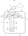
Fig. 2 is a cross-sectional view showing a urea water tank, the liquid level detecting device and the like. -
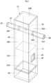
Fig. 3 is a perspective view showing the liquid level detecting device inFig. 2 . -
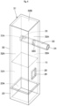
Fig. 4 is a perspective view showing a liquid level detecting device according to a second embodiment. -
Fig. 5 is a perspective view showing a liquid level detecting device according to a third embodiment. - A liquid level detecting device according to one embodiment of the present invention will be described in detail with reference to the attached drawings by way of the case provided to a urea water tank of a wheel loader as a construction machine.
-
Figs. 1 to 3 show a first embodiment. InFig. 1 , awheel loader 1 as a construction machine is configured to include arear vehicle body 2, afront vehicle body 3 connected frontward of therear vehicle body 2 and capable of swinging in the right-and-left direction, arear wheel 4 provided on either side of therear vehicle body 2 in the right-and-left direction, afront wheel 5 provided on either side of thefront vehicle body 3 in the right-and-left direction (therear wheel 4 and thefront wheel 5 shown only on the left side), and aworking mechanism 6 provided frontward of thefront vehicle body 3 and capable of tilting up and down. - Also, the
rear vehicle body 2 is provided with anengine 7 serving as a drive source, atorque converter 8, atransmission 9, a hydraulic pump (not shown) and the like. Theengine 7 is configured as a diesel engine. A later-described exhaust gas purifyingdevice 13 is provided on the exhaust gas side of theengine 7. - A
cab 10 for an on-board operator is provided upward of therear vehicle body 2. Thetransmission 9 is connected to arear axle device 11 via apropeller shaft 9A extending in the front-rear direction. Thetransmission 9 is connected to afront axle device 12 via apropeller shaft 9B. - The exhaust gas purifying
device 13 is provided on the exhaust gas side of theengine 7 to purify exhaust gas discharged by theengine 7. The exhaust gas purifyingdevice 13 is formed as an NOx purifying device purifying nitrogen oxides (NOx) in the exhaust gas, using a later-described urea water (urea water solution) 15. The exhaust gas purifyingdevice 13 has an accommodatingtubular body 13A connected to the exhaust gas side of theengine 7, the accommodatingtubular body 13A including a urea selective reduction catalyst, an oxidation catalyst and a urea water injection valve (each not shown). Theurea water 15 is supplied to the urea water injection valve via a urea water line (not shown) from a later-describedurea water tank 14. - In this configuration, the exhaust gas purifying
device 13 allows the urea water injection valve to inject theurea water 15 into the exhaust gas and the urea selective reduction catalyst to cause a reduction reaction of NOx in the exhaust gas using ammonia generated by theurea water 15 to resolve the urea water into water and nitrogen. Then, the oxidation catalyst reduces the amount of ammonia in the exhaust gas. - The
urea water tank 14 as a liquid tank is provided on the rear side of therear vehicle body 2, for example. As shown inFig. 2 , the ureawater tank 14 reserves theurea water 15 as a reducing agent that is supplied to the urea water injection valve of the exhaust gas purifyingdevice 13. A later-described liquidlevel detecting device 21 is provided at the ureawater tank 14. In addition, theurea water tank 14 is provided with a line connecting with the urea water injection valve, a quality sensor detecting the quality of theurea water 15 and the like (each not shown). - Herein, the
urea water tank 14 can significantly sway when thewheel loader 1 travels or is operated. In this case, theurea water 15 sloshes to generate air bubbles (incl. microbubbles) 15A in the ureawater tank 14. - Subsequently, the configuration of the liquid
level detecting device 21 that constitutes the characterizing portion of the first embodiment of the present invention will be described with reference toFigs. 2 and3 . - In
Fig. 2 , the liquidlevel detecting device 21 is provided at the ureawater tank 14. The liquidlevel detecting device 21 detects a liquid level position of theurea water 15 reserved in theurea water tank 14, that is, a remaining amount of the urea water. The liquidlevel detecting device 21 is configured to include a later-describedcase 22, anultrasonic sensor 23, awater flow hole 25, aventing tube 27, anexternal venting hole 28, and aninternal venting hole 29. - The
case 22 is provided to extend in the vertical direction within theurea water tank 14. Thecase 22, for example, has an upper side (other side) that protrudes from atop surface portion 14A upward and a lower side (one side) that is located near abottom surface portion 14B of theurea water tank 14. As shown inFig 3 , thecase 22 is formed as an angular tubular body whose upper side is closed. Specifically, thecase 22 is composed of fourside surface portions 22A disposed to form a quadrangle and atop surface part 22B closing the upper sides of the fourside surface portions 22A. The lower side of thecase 22 is closed by a later-describedultrasonic sensor 23. The case may have a lower side closed by a bottom surface portion on which an ultrasonic sensor is included. In addition, the case may be formed as a polygonal tube other than a cylindrical body and a quadrangular tube. - Further, the
case 22 includestube mounting holes 22C formed on the upper sides of theside surface portions 22A that are opposite each other. The twotube mounting holes 22C are each disposed to be higher than a liquid level position of theurea water 15 in a filled-up urea water tank. A later-describedventing tube 27 is inserted into the twotube mounting holes 22C. - The
ultrasonic sensor 23 is provided on a lower side or one side of thecase 22. Theultrasonic sensor 23 includes an oscillating and receivingportion 23A including an ultrasound oscillator (piezoelectric device) on an upper surface thereof. In theultrasonic sensor 23, the oscillating and receivingportion 23A can oscillate sound waves and receive the same after reflecting off a liquid level of theurea water 15. Theultrasonic sensor 23 is connected to acontroller 24. - Thereafter, the
ultrasonic sensor 23 transmits a signal to thecontroller 24 indicative of a duration from the oscillation to reception of sound waves by the oscillating and receivingportion 23A. This mechanism allows thecontroller 24 to detect (calculate) a liquid level position of theurea water 15 from the duration from the oscillation to reception of the sound waves. - The
water flow hole 25 is provided on the lower side of theside surface portion 22A of thecase 22 near theultrasonic sensor 23. Thewater flow hole 25 constitutes a passage moving theurea water 15 in and out of thecase 22. - A
film body 26 is provided to cover thewater flow hole 25. Thefilm body 26 is formed of a porous film having numerous micropores. Thefilm body 26 prevents ingress of air bubbles (microbubbles) 15A and allows only theurea water 15 to flow thereinto when theurea water 15 in theurea water tank 14 flows into thecase 22 through thewater flow hole 25. Thus, thefilm body 26 inhibits false detection by sound waves of theultrasonic sensor 23 hitting the air bubbles 15A. - The venting
tube 27 is provided on the upper side of thecase 22 to be higher than a liquid level position of theurea water 15 in a filled-up urea water tank. Specifically, the ventingtube 27 is inserted into thetube mounting holes 22C to extend in the horizontal direction so as to penetrate theside surface portions 22A of thecase 22 that are opposite each other. The ventingtube 27 extends linearly and is formed as a circular tubular body whose both ends are open. In other words, the ventingtube 27 is provided such that two end portions in communication with each other are located outward of thecase 22. Based upon this configuration, the ventingtube 27 protrudes from theside surface portion 22A of thecase 22 outward of thecase 22 to allow a later-describedexternal venting hole 28 to be spaced apart from theside surface portion 22A and in an open state. The venting tube may be elliptically shaped or angularly shaped, in addition to a circular cylinder. - External venting holes 28 are each provided to be open at either end of the venting
tube 27 located outward of thecase 22. Theexternal venting hole 28 is located upward from a liquid level of theurea water 15 and constitutes one venting hole moving the air between the inside and the outside of thecase 22. Theexternal venting hole 28 is disposed to be spaced apart from theside surface portion 22A of thecase 22 outward. The resulting larger distance dimension of theexternal venting hole 28 with a later-describedinternal venting hole 29, even in a case of ingress of theurea water 15 into the ventingtube 27, allows the urea water to stay at a lower position in the ventingtube 27 until theurea water 15 reaches the vicinity of aninternal venting hole 29. In other words, theurea water 15 can be separate from theinternal venting hole 29 in the ventingtube 27. In addition, theexternal venting hole 28 can prevent ingress of theurea water 15 into theexternal venting hole 28 even if theurea water 15 attached to theside surface portion 22A flows down. - The
internal venting hole 29 is provided to be open at an upper position of the ventingtube 27 within thecase 22. Theinternal venting hole 29 constitutes other venting hole moving the air between the inside and the outside of thecase 22. Theinternal venting hole 29 can be open at the upper position of the ventingtube 27 to prevent flow of the urea water into thecase 22, even in a case of ingress of theurea water 15 from theexternal venting hole 28 into the ventingtube 27. - The liquid
level detecting device 21 according to the first embodiment is configured as described above, and subsequently the operation of detecting a liquid level position of theurea water 15 in theurea water tank 14 will be described. - First, with the
urea water 15 in theurea water tank 14 moving in and out of thecase 22 through thewater flow hole 25, liquid level positions of theurea water 15 in and out of the case 22 (within the urea water tank 14) are the same. In this case, thecase 22 is advantageously provided with thefilm body 26 composed of a porous film so as to cover thewater flow hole 25, which can prevent ingress of the air bubbles (microbubbles) 15A when theurea water 15 in theurea water tank 14 flows into thecase 22. - In a case where the level of the
urea water 15 rises or falls in the case 22 (i.e., the liquid level position is displaced in the vertical direction), the air stagnant on the upper side of thecase 22 must be released or the air must be supplied to the case in order to keep the pressures in and out of thecase 22 even. In this case, an upper space in thecase 22 communicates with theurea water tank 14 through theexternal venting hole 28 and theinternal venting hole 29 provided at the ventingtube 27, thereby generating little airflow resistance and freely releasing or supplying the air, depending on the rising or falling level of theurea water 15. That is, the pressures in and out of thecase 22 can be kept even. - Then, the
ultrasonic sensor 23 oscillates sound waves upward from the oscillating and receivingportion 23A. At this time, with theurea water 15 in thecase 22 containing no air bubbles 15A, the oscillating and receivingportion 23A oscillates sound waves and receives the same after the sound waves reflect off a liquid level of theurea water 15. The detection data is transmitted to thecontroller 24, which will detect (calculate) a liquid level position of theurea water 15 from a duration from the oscillation to reception to display a remaining amount of theurea water 15 on a monitor (not shown) in thecab 10. - In fact, in such a working environment as the
wheel loader 1 can repeatedly travel or stop and be operated on rugged land, uneven land, inclined land, as shown inFig. 2 , theurea water 15 in theurea water tank 14 can significantly slosh to allow theurea water 15 containing the air bubbles 15A to reach theexternal venting hole 28. - Therefore, according to the first embodiment, the liquid
level detecting device 21 includes the ventingtube 27 located on the upper side (other side) of thecase 22 opposite thewater flow hole 25 and theultrasonic sensor 23 and provided so as to penetrate theside surface portion 22A of thecase 22. The ventingtube 27 is provided with the external venting holes 28 that are open outward of thecase 22 and theinternal venting hole 29 that is open on the upper side (other side) of thecase 22 within thecase 22 and in communication with the external venting holes 28. - Accordingly, even ingress of the
urea water 15 containing the air bubbles 15A from theexternal venting hole 28 into the ventingtube 27 allows theurea water 15 containing the air bubbles 15A to flow into the urea water tank 14 (out of the case 22) through the ventingtube 27, because theinternal venting hole 29 is open at the upper position of the ventingtube 27. This mechanism can prevent ingress of theurea water 15 containing the air bubbles 15A from theexternal venting hole 28 and theinternal venting hole 29 into thecase 22. In other words, entry of the air bubbles 15A into theurea water 15 within thecase 22 can be prevented. Consequently, theultrasonic sensor 23 can properly be operated, and the reliability for the detection of a liquid level position of theurea water 15 can be improved. - The venting
tube 27 is provided such that two end portions thereof in communication with each other are located outward of thecase 22. Based upon this configuration, the external venting holes 28 are disposed at two end portions of the ventingtube 27. In this configuration, in a case where a vehicle body of thewheel loader 1 inclines during the operation on rugged land, uneven land or inclined land, theurea water 15 containing the air bubbles 15A can assuredly be flowed out of theexternal venting hole 28 provided at a lower end portion of the two end portions. - The venting
tube 27 protrudes from theside surface portion 22A of thecase 22, and theexternal venting hole 28 is disposed to be spaced apart from theside surface portion 22A of thecase 22 outward. Accordingly, theexternal venting hole 28 is significantly separate from theinternal venting hole 29. This configuration, even in a case of ingress of theurea water 15 from theexternal venting hole 28 into the ventingtube 27, allows the ventingtube 27 to cause the urea water to stay at a lower position in the ventingtube 27 until theurea water 15 reaches the vicinity of theinternal venting hole 29. In addition, the ventingtube 27 can prevent ingress of theurea water 15 into theexternal venting hole 28 even if theurea water 15 attached to theside surface portion 22A flows down. - The venting
tube 27 has both end portions, each corresponding to theexternal venting hole 28 and formed of a cylindrical pipe member. In addition, the ventingtube 27 is provided so as to penetrate theside surface portions 22A of thecase 22 that are opposite each other. This configuration can readily form a ventingtube 27 using a linear pipe member. - Subsequently,
Fig. 4 shows a second embodiment of the present invention. The characteristic of the second embodiment lies in the configuration where a venting tube penetrating a side surface portion of a case is formed as a tubular body having an external end portion of the case that is open and an internal end portion of the case that is closed. In the second embodiment, the component elements that are identical to those of the foregoing first embodiment will be simply denoted by the same reference numerals to avoid repetitions of similar explanations. - In
Fig. 4 , a liquidlevel detecting device 31 according to the second embodiment includes acase 32. Thecase 32 has fourside surface portions 32A and atop surface part 32B, one of theside surface portions 32A provided with a singletube mounting hole 32C higher than a liquid level position of aurea water 15 in a filled-up urea water tank. In addition, the case may be formed as a polygonal tube other than a cylindrical body and a quadrangular tube. - A venting
tube 33 is inserted into thetube mounting holes 32C to extend in the horizontal direction so as to penetrate theside surface portion 32A of thecase 32. The ventingtube 33 is formed as a lidded circular tubular body having a linearly extending external end portion that is open out of thecase 32 and an internal end portion that is closed with alid portion 33A in thecase 32. The ventingtube 33, similarly to the ventingtube 27 according to the first embodiment, has the external end portion out of thecase 32 that protrudes from theside surface portion 32A. - An
external venting hole 34 is open at an end portion of the ventingtube 33 out of thecase 32. Aninternal venting hole 35 is in communication with theexternal venting hole 34 through the ventingtube 33 and open at an upper position of the ventingtube 33 within thecase 32. - Thus, the liquid
level detecting device 31 according to the second embodiment thus configured can provide a similar operational effect as the first embodiment. In particular, a liquidlevel detecting device 31 according to the second embodiment can be formed only by inserting a ventingtube 33 into oneside surface portion 32A, resulting in a simplified configuration. - Subsequently,
Fig. 5 shows a third embodiment of the present invention. The characteristic of the third embodiment lies in the configuration where a bent venting tube is provided so as to penetrate adjacent side surface portions of a case. In the third embodiment, the component elements that are identical to those of the foregoing first embodiment will be simply denoted by the same reference numerals to avoid repetitions of similar explanations. - In
Fig. 5 , a liquidlevel detecting device 41 according to the third embodiment includes acase 42. Thecase 42 has fourside surface portions 42A and atop surface part 42B, two adjacentside surface portions 42A provided with atube mounting hole 42C higher than a liquid level position of aurea water 15 in a filled-up urea water tank. In addition, the case may be formed as a polygonal tube other than a cylindrical body and a quadrangular tube. - A venting
tube 43 is formed as an L-shaped tubular body such that an intermediate portion in a length direction bends as a bendingportion 43A. The L-shapedventing tube 43 is inserted into thetube mounting hole 42C to extend in the horizontal direction so as to penetrate the adjacentside surface portions 42A of thecase 42. The ventingtube 43, similarly to the ventingtube 27 according to the first embodiment, has an end portion out of thecase 42 that protrudes from theside surface portion 42A. - External venting holes 44 are disposed at two end portions of the venting
tube 43 out of thecase 42. Aninternal venting hole 45 is in communication with the external venting holes 44 through the ventingtube 43 and disposed at an upper position of the bendingportion 43A of the ventingtube 43 within thecase 42. - Thus, the liquid
level detecting device 41 according to the third embodiment thus configured can provide a similar operational effect as the first embodiment. - In the first embodiment, the case where the venting
tube 27 is allowed to penetrate twoside surface portions 22A of thecase 22, and in the second embodiment, the ventingtube 33 is allowed to penetrate oneside surface portion 32A of thecase 32 is illustrated. However, the present invention is not limited to that, and the venting tube may be configured to be trifurcate such as T-shaped or Y-shaped, penetrating three side surface portions. Also, the venting tube may be configured to be cross-shaped, penetrating four side surface portions. - In the first embodiment, the case where the liquid
level detecting device 21 is provided at theurea water tank 14 of thewheel loader 1 as a construction machine is illustrated. However, the present invention is not limited to that, and a liquid level detecting device may be provided in a urea water tank of other type of construction machine such as a hydraulic excavator. Also, the liquid level detecting device can be used for detecting a liquid level position of a liquid other than urea water (e.g., fuels, water). These configurations can apply to other embodiments. -
- 15: Urea water (Liquid)
- 15A: Air bubble
- 21, 31, 41: Liquid level detecting device
- 22, 32, 42: Case
- 22A, 32A, 42A: Side surface portion
- 23: Ultrasonic sensor
- 25: Water flow hole
- 27, 33, 43: Venting tube
- 28, 34, 44: External venting hole
- 29, 35, 45: Internal venting hole
Claims (5)
- A liquid level detecting device comprising:a tubular case with a water flow hole allowing a liquid to flow into the case; andan ultrasonic sensor provided on one side of the case and oscillating and receiving ultrasound, the liquid level detecting device further comprisinga venting tube located on other side of the case opposite the water flow hole and the ultrasonic sensor and provided so as to penetrate a side surface portion of the case, whereinthe venting tube is provided with an external venting hole that is open outward of the case and an internal venting hole that is open on the other side of the case within the case and in communication with the external venting hole.
- The liquid level detecting device according to claim 1, whereinthe venting tube is provided such that a plurality of end portions in communication with each other is located outward of the case, whereinthe external venting holes are formed at the plurality of end portions.
- The liquid level detecting device according to claim 1, whereinthe venting tube protrudes outward of the side surface portion of the case, andthe external venting hole is formed to be spaced apart outward of the side surface portion of the case.
- The liquid level detecting device according to claim 1, wherein
the venting tube has both end portions, each corresponding to the external venting hole and formed of a cylindrical pipe member. - The liquid level detecting device according to claim 3, wherein
the venting tube is provided so as to penetrate the side surface portions of the case that are opposite each other.
Applications Claiming Priority (2)
| Application Number | Priority Date | Filing Date | Title |
|---|---|---|---|
| JP2022182501 | 2022-11-15 | ||
| PCT/JP2023/037017 WO2024106087A1 (en) | 2022-11-15 | 2023-10-12 | Liquid level detecting device |
Publications (2)
| Publication Number | Publication Date |
|---|---|
| EP4553297A1 true EP4553297A1 (en) | 2025-05-14 |
| EP4553297A4 EP4553297A4 (en) | 2026-04-08 |
Family
ID=91084108
Family Applications (1)
| Application Number | Title | Priority Date | Filing Date |
|---|---|---|---|
| EP23891245.5A Pending EP4553297A4 (en) | 2022-11-15 | 2023-10-12 | DEVICE FOR LIQUID LEVEL DETECTION |
Country Status (6)
| Country | Link |
|---|---|
| US (1) | US20260063462A1 (en) |
| EP (1) | EP4553297A4 (en) |
| JP (1) | JP7736947B2 (en) |
| KR (1) | KR20250042803A (en) |
| CN (1) | CN119698518A (en) |
| WO (1) | WO2024106087A1 (en) |
Family Cites Families (8)
| Publication number | Priority date | Publication date | Assignee | Title |
|---|---|---|---|---|
| EP1748285A1 (en) * | 2005-07-29 | 2007-01-31 | Truma Gerätetechnik GmbH & Co. KG | Ultrasound level detecting apparatus with threshold level detection |
| DE102007059853B4 (en) * | 2007-12-12 | 2018-01-25 | Robert Bosch Gmbh | Device for measuring a level of a liquid in a container |
| CN205785188U (en) * | 2016-06-30 | 2016-12-07 | 嘉兴同禾传感技术有限公司 | A kind of device of static level level measuring based on ultrasonic ranging principle |
| JP2019053031A (en) * | 2017-09-14 | 2019-04-04 | 株式会社デンソー | Liquid level detector |
| JP6911662B2 (en) * | 2017-09-14 | 2021-07-28 | 株式会社デンソー | Liquid level detector |
| US11965768B2 (en) | 2018-04-25 | 2024-04-23 | Shaw Development, Llc | Device with aeration mitigation for improved measurement of fluids |
| JP7073989B2 (en) | 2018-08-31 | 2022-05-24 | 株式会社三洋物産 | Pachinko machine |
| CN110260948B (en) * | 2019-06-20 | 2020-07-24 | 杭州电子科技大学 | Liquid level measuring method based on acoustic resonance frequency nonlinear filtering |
-
2023
- 2023-10-12 US US19/106,656 patent/US20260063462A1/en active Pending
- 2023-10-12 WO PCT/JP2023/037017 patent/WO2024106087A1/en not_active Ceased
- 2023-10-12 JP JP2024558704A patent/JP7736947B2/en active Active
- 2023-10-12 CN CN202380061919.9A patent/CN119698518A/en active Pending
- 2023-10-12 KR KR1020257006060A patent/KR20250042803A/en active Pending
- 2023-10-12 EP EP23891245.5A patent/EP4553297A4/en active Pending
Also Published As
| Publication number | Publication date |
|---|---|
| KR20250042803A (en) | 2025-03-27 |
| EP4553297A4 (en) | 2026-04-08 |
| JP7736947B2 (en) | 2025-09-09 |
| CN119698518A (en) | 2025-03-25 |
| JPWO2024106087A1 (en) | 2024-05-23 |
| US20260063462A1 (en) | 2026-03-05 |
| WO2024106087A1 (en) | 2024-05-23 |
Similar Documents
| Publication | Publication Date | Title |
|---|---|---|
| EP2006503B1 (en) | Liquid tank, breather device for the liquid tank, and exhaust gas purification device for engine | |
| EP2006502B1 (en) | Breather device, liquid tank, and exhaust gas purifying device for engine | |
| US6629457B1 (en) | Device for measuring a fill level of a liquid in a container | |
| US20150089996A1 (en) | Reduction of aeration interference in an ultrasonic fluid sensing system | |
| US20120304626A1 (en) | Method for determining an amount of liquid removed from a tank and reducing agent supply device for a motor vehicle | |
| US20120006832A1 (en) | Storage tank | |
| JP2016151489A (en) | Urea water concentration measurement device of construction machine | |
| CN105556259B (en) | For by can frozen liquid be introduced into the equipment in the exhaust system of motor vehicles | |
| US10234323B2 (en) | Method for determining a liquid level and quality in a tank | |
| US9804004B1 (en) | Fluid quality sensor and cover assembly | |
| US20260063462A1 (en) | Liquid level detecting device | |
| US9815332B2 (en) | Working vehicle | |
| JP6392728B2 (en) | Exhaust gas purification equipment for work machines | |
| US10753250B2 (en) | Universal shutoff valve | |
| CN216008650U (en) | Urea quality sensor | |
| EP2495542A1 (en) | Fuel property detection device for construction equipment and construction equipment provided therewith | |
| JP7108498B2 (en) | Reductant tank and exhaust purification device | |
| JP4799079B2 (en) | Liquid tank device | |
| CN104246158A (en) | Device for supplying a liquid additive | |
| WO2014065260A1 (en) | Urea water tank | |
| US11319852B2 (en) | Systems and methods for fluid level and quality measurement for reductant storage systems | |
| KR102839098B1 (en) | Method for detecting incorrect refueling of a storage container in a motor vehicle | |
| JP4437263B2 (en) | Fuel additive supply device | |
| KR100682568B1 (en) | Fuel supply device for liquefied gas | |
| GB2525414A (en) | Fuel pump module for a fuel tank |
Legal Events
| Date | Code | Title | Description |
|---|---|---|---|
| STAA | Information on the status of an ep patent application or granted ep patent |
Free format text: STATUS: THE INTERNATIONAL PUBLICATION HAS BEEN MADE |
|
| PUAI | Public reference made under article 153(3) epc to a published international application that has entered the european phase |
Free format text: ORIGINAL CODE: 0009012 |
|
| STAA | Information on the status of an ep patent application or granted ep patent |
Free format text: STATUS: REQUEST FOR EXAMINATION WAS MADE |
|
| 17P | Request for examination filed |
Effective date: 20250210 |
|
| AK | Designated contracting states |
Kind code of ref document: A1 Designated state(s): AL AT BE BG CH CY CZ DE DK EE ES FI FR GB GR HR HU IE IS IT LI LT LU LV MC ME MK MT NL NO PL PT RO RS SE SI SK SM TR |
|
| DAV | Request for validation of the european patent (deleted) | ||
| DAX | Request for extension of the european patent (deleted) | ||
| A4 | Supplementary search report drawn up and despatched |
Effective date: 20260306 |
|
| RIC1 | Information provided on ipc code assigned before grant |
Ipc: F01N 3/08 20060101AFI20260302BHEP Ipc: G01F 23/2962 20220101ALI20260302BHEP Ipc: F01N 3/20 20060101ALI20260302BHEP |