EP4553273A1 - Piston seal ring with flow bypass - Google Patents
Piston seal ring with flow bypass Download PDFInfo
- Publication number
- EP4553273A1 EP4553273A1 EP24212161.4A EP24212161A EP4553273A1 EP 4553273 A1 EP4553273 A1 EP 4553273A1 EP 24212161 A EP24212161 A EP 24212161A EP 4553273 A1 EP4553273 A1 EP 4553273A1
- Authority
- EP
- European Patent Office
- Prior art keywords
- rotor element
- psr
- flow channels
- bypass flow
- gas turbine
- Prior art date
- Legal status (The legal status is an assumption and is not a legal conclusion. Google has not performed a legal analysis and makes no representation as to the accuracy of the status listed.)
- Pending
Links
Images



Classifications
-
- F—MECHANICAL ENGINEERING; LIGHTING; HEATING; WEAPONS; BLASTING
- F01—MACHINES OR ENGINES IN GENERAL; ENGINE PLANTS IN GENERAL; STEAM ENGINES
- F01D—NON-POSITIVE DISPLACEMENT MACHINES OR ENGINES, e.g. STEAM TURBINES
- F01D11/00—Preventing or minimising internal leakage of working-fluid, e.g. between stages
- F01D11/003—Preventing or minimising internal leakage of working-fluid, e.g. between stages by packing rings; Mechanical seals
-
- F—MECHANICAL ENGINEERING; LIGHTING; HEATING; WEAPONS; BLASTING
- F01—MACHINES OR ENGINES IN GENERAL; ENGINE PLANTS IN GENERAL; STEAM ENGINES
- F01D—NON-POSITIVE DISPLACEMENT MACHINES OR ENGINES, e.g. STEAM TURBINES
- F01D11/00—Preventing or minimising internal leakage of working-fluid, e.g. between stages
- F01D11/005—Sealing means between non relatively rotating elements
-
- F—MECHANICAL ENGINEERING; LIGHTING; HEATING; WEAPONS; BLASTING
- F01—MACHINES OR ENGINES IN GENERAL; ENGINE PLANTS IN GENERAL; STEAM ENGINES
- F01D—NON-POSITIVE DISPLACEMENT MACHINES OR ENGINES, e.g. STEAM TURBINES
- F01D17/00—Regulating or controlling by varying flow
- F01D17/10—Final actuators
- F01D17/105—Final actuators by passing part of the fluid
-
- F—MECHANICAL ENGINEERING; LIGHTING; HEATING; WEAPONS; BLASTING
- F01—MACHINES OR ENGINES IN GENERAL; ENGINE PLANTS IN GENERAL; STEAM ENGINES
- F01D—NON-POSITIVE DISPLACEMENT MACHINES OR ENGINES, e.g. STEAM TURBINES
- F01D5/00—Blades; Blade-carrying members; Heating, heat-insulating, cooling or antivibration means on the blades or the members
- F01D5/02—Blade-carrying members, e.g. rotors
- F01D5/06—Rotors for more than one axial stage, e.g. of drum or multiple disc type; Details thereof, e.g. shafts, shaft connections
- F01D5/066—Connecting means for joining rotor-discs or rotor-elements together, e.g. by a central bolt, by clamps
-
- F—MECHANICAL ENGINEERING; LIGHTING; HEATING; WEAPONS; BLASTING
- F16—ENGINEERING ELEMENTS AND UNITS; GENERAL MEASURES FOR PRODUCING AND MAINTAINING EFFECTIVE FUNCTIONING OF MACHINES OR INSTALLATIONS; THERMAL INSULATION IN GENERAL
- F16J—PISTONS; CYLINDERS; SEALINGS
- F16J1/00—Pistons; Trunk pistons; Plungers
-
- F—MECHANICAL ENGINEERING; LIGHTING; HEATING; WEAPONS; BLASTING
- F16—ENGINEERING ELEMENTS AND UNITS; GENERAL MEASURES FOR PRODUCING AND MAINTAINING EFFECTIVE FUNCTIONING OF MACHINES OR INSTALLATIONS; THERMAL INSULATION IN GENERAL
- F16J—PISTONS; CYLINDERS; SEALINGS
- F16J15/00—Sealings
-
- F—MECHANICAL ENGINEERING; LIGHTING; HEATING; WEAPONS; BLASTING
- F05—INDEXING SCHEMES RELATING TO ENGINES OR PUMPS IN VARIOUS SUBCLASSES OF CLASSES F01-F04
- F05D—INDEXING SCHEME FOR ASPECTS RELATING TO NON-POSITIVE-DISPLACEMENT MACHINES OR ENGINES, GAS-TURBINES OR JET-PROPULSION PLANTS
- F05D2220/00—Application
- F05D2220/30—Application in turbines
- F05D2220/32—Application in turbines in gas turbines
- F05D2220/321—Application in turbines in gas turbines for a special turbine stage
- F05D2220/3216—Application in turbines in gas turbines for a special turbine stage for a special compressor stage
- F05D2220/3219—Application in turbines in gas turbines for a special turbine stage for a special compressor stage for the last stage of a compressor or a high pressure compressor
-
- F—MECHANICAL ENGINEERING; LIGHTING; HEATING; WEAPONS; BLASTING
- F05—INDEXING SCHEMES RELATING TO ENGINES OR PUMPS IN VARIOUS SUBCLASSES OF CLASSES F01-F04
- F05D—INDEXING SCHEME FOR ASPECTS RELATING TO NON-POSITIVE-DISPLACEMENT MACHINES OR ENGINES, GAS-TURBINES OR JET-PROPULSION PLANTS
- F05D2240/00—Components
- F05D2240/55—Seals
- F05D2240/58—Piston ring seals
-
- F—MECHANICAL ENGINEERING; LIGHTING; HEATING; WEAPONS; BLASTING
- F05—INDEXING SCHEMES RELATING TO ENGINES OR PUMPS IN VARIOUS SUBCLASSES OF CLASSES F01-F04
- F05D—INDEXING SCHEME FOR ASPECTS RELATING TO NON-POSITIVE-DISPLACEMENT MACHINES OR ENGINES, GAS-TURBINES OR JET-PROPULSION PLANTS
- F05D2260/00—Function
- F05D2260/60—Fluid transfer
- F05D2260/606—Bypassing the fluid
Definitions
- Exemplary embodiments of the present disclosure relate generally to gas turbine engines and, in one embodiment, to a gas turbine engine with a non-speed differential seal flow bypass.
- piston seal rings In a gas turbine engine, piston seal rings (PSR) are designed to maintain sealing contact between two solid bodies and operate by restricting flows of fluid, gas or air.
- a PSR can be used in static or rotating applications and usually is housed within a groove where the PSR has both axial and radial contact with adjacent hardware. These solid axial and radial contacts provide restriction to avoid mixing of fluid, gas or air from one compartment of the gas turbine engine to another.
- PSRs can be found throughout jet engines and in some locations their seal is essential in order to maintain engine performance and part durability.
- a gas turbine engine includes a first rotor element defining a groove, a second rotor element disposed to rotate about the first rotor element and a piston seal ring (PSR) disposed in the groove to form a seal between the first rotor element and the second rotor element.
- the second rotor element is formed to define bypass flow channels about the PSR that extend between opposite axial sides of the PSR.
- the first rotor element includes at least a tie shaft and the second rotor element includes at least a rotor bore.
- the PSR includes opposite ends, a joint at which the opposite ends register with each other and entirely smooth and continuous axial and radial surfaces extending between the opposite ends.
- bypass flow channels are distributed evenly about the PSR.
- bypass flow channels begin at a first plenum at an upstream side of the PSR and terminate at a second plenum at a downstream side of the PSR.
- the second rotor element includes an interior facing surface and the second rotor element is formed to define each of the bypass flow channels as a slot extending along the interior facing surface.
- the second rotor element includes a body and the second rotor element is formed to define each of the bypass flow channels as a through-hole extending through the body.
- bypass flow channels are angled in correspondence with a direction of rotation of the second rotor element.
- bypass flow channels are angled in opposition to a direction of rotation of the second rotor element.
- a gas turbine engine includes a first rotor element defining a groove, a second rotor element disposed to rotate about the first rotor element and a piston seal ring (PSR) disposed in the groove to form a seal between the first rotor element and the second rotor element.
- the second rotor element is formed to define bypass flow channels about the PSR that extend between opposite axial sides of the PSR such that the bypass flow channels form a symmetric leak path across the PSR.
- the first rotor element includes at least a tie shaft and the second rotor element includes at least a rotor bore.
- the PSR includes opposite ends, a joint at which the opposite ends register with each other and entirely smooth and continuous axial and radial surfaces extending between the opposite ends.
- bypass flow channels are distributed evenly about the PSR.
- bypass flow channels begin at a first plenum at an upstream side of the PSR and terminate at a second plenum at a downstream side of the PSR.
- the second rotor element includes an interior facing surface and the second rotor element is formed to define each of the bypass flow channels as a slot extending along the interior facing surface.
- the second rotor element includes a body and the second rotor element is formed to define each of the bypass flow channels as a through-hole extending through the body.
- bypass flow channels are angled in correspondence with a direction of rotation of the second rotor element.
- bypass flow channels are angled in opposition to a direction of rotation of the second rotor element.
- a gas turbine engine includes a first rotor element defining a groove, a second rotor element disposed to rotate about the first rotor element and a piston seal ring (PSR) disposed in the groove to form a seal between the first rotor element and the second rotor element.
- the second rotor element is formed to define first bypass flow channels about the PSR that extend between opposite axial sides of the PSR and the first rotor element is formed to define second bypass flow channels along an interior surface of the PSR that extend between the opposite axial sides of the PSR.
- the first and second bypass flow channels form first and second symmetric leak paths across the PSR.
- FIG. 1 schematically illustrates a gas turbine engine 20.
- the gas turbine engine 20 is disclosed herein as a two-spool turbofan that generally incorporates a fan section 22, a compressor section 24, a combustor section 26 and a turbine section 28.
- Alternative engines might include other systems or features.
- the fan section 22 drives air along a bypass flow path B in a bypass duct, while the compressor section 24 drives air along a core flow path C for compression and communication into the combustor section 26 and then expansion through the turbine section 28.
- the exemplary gas turbine engine 20 generally includes a low speed spool 30 and a high speed spool 32 mounted for rotation about an engine central longitudinal axis A relative to an engine static structure 36 via several bearing systems 38. It should be understood that various bearing systems 38 at various locations may alternatively or additionally be provided, and the location of bearing systems 38 may be varied as appropriate to the application.
- the low speed spool 30 generally includes an inner shaft 40 that interconnects a fan 42, a low pressure compressor 44 and a low pressure turbine 46.
- the inner shaft 40 is connected to the fan 42 through a speed change mechanism, which in exemplary gas turbine engine 20 is illustrated as a geared architecture 48 to drive the fan 42 at a lower speed than the low speed spool 30.
- the high speed spool 32 includes an outer shaft 50 that interconnects a high pressure compressor 52 and high pressure turbine 54.
- a combustor 56 is arranged in the gas turbine engine 20 between the high pressure compressor 52 and the high pressure turbine 54.
- the engine static structure 36 is arranged generally between the high pressure turbine 54 and the low pressure turbine 46.
- the engine static structure 36 further supports the bearing systems 38 in the turbine section 28.
- the inner shaft 40 and the outer shaft 50 are concentric and rotate via bearing systems 38 about the engine central longitudinal axis A which is collinear with their longitudinal axes.
- the core airflow is compressed by the low pressure compressor 44 and then the high pressure compressor 52, is mixed and burned with fuel in the combustor 56 and is then expanded over the high pressure turbine 54 and the low pressure turbine 46.
- the high and low pressure turbines 54 and 46 rotationally drive the low speed spool 30 and the high speed spool 32, respectively, in response to the expansion.
- geared architecture 48 may be located aft of the combustor section 26 or even aft of the turbine section 28, and the fan section 22 may be positioned forward or aft of the location of geared architecture 48.
- a piston seal ring (PSR) 201 is provided for use in the gas turbine engine 20 of FIG. 1 in at least the compressor section 24.
- the PSR 201 can be formed as a split ring seal having a first circumferential end 210, a second circumferential end 211, an interior facing inner diameter (ID) surface 220, an exterior facing outer diameter (OD) surface 222, a first axial end face 230 and a second axial end face 231.
- the PSR 201 has a nominal central longitudinal axis (centerline) 202 that is shared with the members it seals when in a nominally centered condition.
- the first circumferential end 210 and the second circumferential end 211 form a joint or junction 240 (see FIG.
- the joint orjunction 240 can be provided as a shiplap joint with a projecting portion 241 of the first circumferential end 210 being received by a rebate 242 of the second circumferential end 211 and a projecting portion 243 of the second circumferential 211 end being received by a rebate 244 in the first circumferential end 210.
- the example projecting portions have mating faces/surfaces 250 and 251 which, in the example, closely face or contact along a transverse radial centerplane.
- PSRs such as the PSR 201 of FIGS. 2 and 3
- PSRs are often small in cross section and made of relatively soft material as compared to the surrounding hardware.
- PSRs are typically split for assembly purposes (i.e., the joint or junction 240 of FIGS. 2 and 3 ) and therefore may have little or limited hoop strength.
- the overlap at the split of the PSRs as well as manufacturing processes and operational loading and wear can cause the sealing surfaces of PSRs to have flatness and/or circularity errors that allow for local leakage. Often this leakage is non-axisymmetric.
- Such non-axisymmetric leakage leads to local thermal hotspots on the surrounding hardware that can, in turn, lead to non-axisymmetric distortion of the surrounding hardware resulting in mass unbalance, localized stress concentrations and reduced sealing performance.
- bypass flows are implemented evenly around the hardware surrounding the PSR.
- the bypass flows essentially trade some of the sealing effectiveness of the PSR for uniform thermal behavior.
- the usage of the bypass flows in this manner avoids any need to form bypass slots or channels in the PSR, which is itself already thin, and allows for reduced structural risk in the PSR.
- the bypass flows can be formed as channels or slots in the surrounding hardware, such as the rotor bore and the tie shaft.
- section 401 of a gas turbine engine such as the compression section 24 of the gas turbine engine 20 of FIG. 1 , includes a first rotor element 410 defining a continuous circumferential groove 411, a second rotor element 420 that is disposed to rotate about the first rotor element 410 and a PSR 430.
- the first rotor element 410 can be provided at least as a tie shaft 412 or another similar feature and the second rotor element 420 can be provided at least as a rotor bore 421 or another similar feature.
- the PSR 430 includes opposite ends (i.e., first circumferential end 210 and second circumferential end 211 of FIG.
- a joint at which the opposite ends register with each other i.e., the joint or junction 240 of FIGS. 2 and 3
- entirely smooth and continuous axial and radial surfaces extending between the opposite ends i.e., ID surface 220, OD surface 222, first axial end face 230 and second axial end face 231 of FIG. 2 ).
- the PSR 430 is disposed in the continuous circumferential groove 411 to form a continuous circumferential seal 431 between the first rotor element 410 and the second rotor element 420.
- the second rotor element 420 is formed to define bypass flow channels 422 about the PSR 430 that extend between opposite axial sides 432, 433 of the PSR 430.
- the second rotor element 420 is formed to define the bypass flow channels 422 such that the bypass flow channels 422 form a symmetric leak path 440 across the PSR 430.
- bypass flow channels 422 defined by the second rotor element 420 can be provided as first bypass flow channels whereas the first rotor element 410 can also be formed to define bypass flow channels 422' as second bypass flow channels.
- These bypass flow channels 422' would thus extend along an interior surface of the PSR 430 and as above would extend between the opposite axial sides 432, 433 of the PSR 430 to contribute to the formation of the symmetric leak path 440 (i.e., to form first and second symmetric leak paths).
- bypass flow channels 422 can be configured such that they begin at a first plenum 450 at an upstream side of the PSR 430 and terminate at a second plenum 451 at a downstream side of the PSR 430.
- the bypass flow channels 422 are distributed substantially evenly about the PSR 430. In this way, while leakage across the PSR 430 can be non-axisymmetric, the bypass flow channels 422 form the symmetric leak path 440 which is axi-symmetric. Moreover, the volume of the fluid moving through the bypass flow channels 422 can significantly exceed and effectively overwhelm the volume of non-axisymmetric leakage across the PSR 430. As a result, thermal responses of the hardware surrounding the PSR (i.e., the first rotor element 420 and the second rotor element 420) can be controlled in an axi-symmetric manner.
- the second rotor element 420 can include an interior facing surface 423.
- the interior surface 423 of the second rotor element 420 can be formed to define each of the bypass flow channels 422 as a slot 501 (see FIG. 5 ) that extends along the interior facing surface 423 in an axial dimension and/or in an axial and a circumferential dimension.
- the bypass flow channels 422 can be angled. As shown in FIG. 6 , the bypass flow channels 422 can be angled at angle A1 in correspondence with a direction of rotation of the second rotor element 420 to encourage and entrain flow through the bypass flow channels. As shown in FIG. 7 , the bypass flow channels 422 can be angled at angle A2 in opposition to the direction of rotation of the second rotor element 420.
- the angle A1 can be between 0° and 70° or, more narrowly, between 20° and 35° and the angle A2 can be between 0° and 70° or, more narrowly, between 20° and 35° (the angles A1 and A2 in FIGS. 6 and 7 are not drawn to scale).
- the second rotor element 420 can include a body 424.
- the body 424 of the second rotor element 420 can be formed to define each of the bypass flow channels (i.e., each of the bypass flow channels 422 of FIG. 4 ) as a through-hole 801 that extends through the body 424.
- the through-holes as bypass flow channels of the embodiments of FIGS. 8 and 9 are other otherwise configured similarly as described above and need not be re-described.
- bypass flows reduce manufacturability difficulties and allow for reduced structural risk to the PSR by not having bypass slots or channels formed therein.
Landscapes
- Engineering & Computer Science (AREA)
- General Engineering & Computer Science (AREA)
- Mechanical Engineering (AREA)
- Chemical & Material Sciences (AREA)
- Combustion & Propulsion (AREA)
- Turbine Rotor Nozzle Sealing (AREA)
Abstract
A gas turbine engine (20) is provided and includes a first rotor element (410) defining a groove, a second rotor element (420) disposed to rotate about the first rotor element (410) and a piston seal ring (PSR) (430) disposed in the groove to form a seal between the first rotor element (410) and the second rotor element (420). The second rotor element (420) is formed to define bypass flow channels (422) about the PSR (430) that extend between opposite axial sides (432, 433) of the PSR (430).
Description
- Exemplary embodiments of the present disclosure relate generally to gas turbine engines and, in one embodiment, to a gas turbine engine with a non-speed differential seal flow bypass.
- In a gas turbine engine, piston seal rings (PSR) are designed to maintain sealing contact between two solid bodies and operate by restricting flows of fluid, gas or air. A PSR can be used in static or rotating applications and usually is housed within a groove where the PSR has both axial and radial contact with adjacent hardware. These solid axial and radial contacts provide restriction to avoid mixing of fluid, gas or air from one compartment of the gas turbine engine to another. PSRs can be found throughout jet engines and in some locations their seal is essential in order to maintain engine performance and part durability.
- Accordingly, a continued need exists for improved PSRs for use in gas turbine engines, in particular.
- According to an aspect of the disclosure, a gas turbine engine is provided and includes a first rotor element defining a groove, a second rotor element disposed to rotate about the first rotor element and a piston seal ring (PSR) disposed in the groove to form a seal between the first rotor element and the second rotor element. The second rotor element is formed to define bypass flow channels about the PSR that extend between opposite axial sides of the PSR.
- In a further embodiment of the previous embodiment, the first rotor element includes at least a tie shaft and the second rotor element includes at least a rotor bore.
- In a further embodiment of any of the previous embodiments, the PSR includes opposite ends, a joint at which the opposite ends register with each other and entirely smooth and continuous axial and radial surfaces extending between the opposite ends.
- In a further embodiment of any of the previous embodiments, the bypass flow channels are distributed evenly about the PSR.
- In a further embodiment of any of the previous embodiments, the bypass flow channels begin at a first plenum at an upstream side of the PSR and terminate at a second plenum at a downstream side of the PSR.
- In a further embodiment of any of the previous embodiments, the second rotor element includes an interior facing surface and the second rotor element is formed to define each of the bypass flow channels as a slot extending along the interior facing surface.
- In a further embodiment of any of the previous embodiments, the second rotor element includes a body and the second rotor element is formed to define each of the bypass flow channels as a through-hole extending through the body.
- In a further embodiment of any of the previous embodiments, the bypass flow channels are angled in correspondence with a direction of rotation of the second rotor element.
- In a further embodiment of any of the previous embodiments, the bypass flow channels are angled in opposition to a direction of rotation of the second rotor element.
- According to an aspect of the disclosure, a gas turbine engine is provided and includes a first rotor element defining a groove, a second rotor element disposed to rotate about the first rotor element and a piston seal ring (PSR) disposed in the groove to form a seal between the first rotor element and the second rotor element. The second rotor element is formed to define bypass flow channels about the PSR that extend between opposite axial sides of the PSR such that the bypass flow channels form a symmetric leak path across the PSR.
- In a further embodiment of any of the previous embodiments, the first rotor element includes at least a tie shaft and the second rotor element includes at least a rotor bore.
- In a further embodiment of any of the previous embodiments, the PSR includes opposite ends, a joint at which the opposite ends register with each other and entirely smooth and continuous axial and radial surfaces extending between the opposite ends.
- In a further embodiment of any of the previous embodiments, the bypass flow channels are distributed evenly about the PSR.
- In a further embodiment of any of the previous embodiments, the bypass flow channels begin at a first plenum at an upstream side of the PSR and terminate at a second plenum at a downstream side of the PSR.
- In a further embodiment of any of the previous embodiments, the second rotor element includes an interior facing surface and the second rotor element is formed to define each of the bypass flow channels as a slot extending along the interior facing surface.
- In a further embodiment of any of the previous embodiments, the second rotor element includes a body and the second rotor element is formed to define each of the bypass flow channels as a through-hole extending through the body.
- In a further embodiment of any of the previous embodiments, the bypass flow channels are angled in correspondence with a direction of rotation of the second rotor element.
- In a further embodiment of any of the previous embodiments, the bypass flow channels are angled in opposition to a direction of rotation of the second rotor element.
- According to an aspect of the disclosure, a gas turbine engine is provided and includes a first rotor element defining a groove, a second rotor element disposed to rotate about the first rotor element and a piston seal ring (PSR) disposed in the groove to form a seal between the first rotor element and the second rotor element. The second rotor element is formed to define first bypass flow channels about the PSR that extend between opposite axial sides of the PSR and the first rotor element is formed to define second bypass flow channels along an interior surface of the PSR that extend between the opposite axial sides of the PSR.
- In a further embodiment of any of the previous embodiments, the first and second bypass flow channels form first and second symmetric leak paths across the PSR.
- These and other advantages and features will become more apparent from the following description taken in conjunction with the drawings.
- The following descriptions should not be considered limiting in any way. With reference to the accompanying drawings, like elements are numbered alike:
-
FIG. 1 is a partial cross-sectional view of a gas turbine engine; -
FIG. 2 is a perspective view of piston seal ring in accordance with embodiments; -
FIG. 3 is an enlarged cutaway perspective view of a portion of the piston seal ring ofFIG. 2 in accordance with embodiments; -
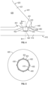
FIG. 4 is a side schematic illustration of first and second rotor elements, a piston seal ring and bypass flow channels formed along an interior surface of the second rotor element in accordance with embodiments; -
FIG. 5 is a cross-sectional view of first and second rotor elements, a piston seal ring and bypass flow channels formed along the interior surface of the second rotor element taken along line 5-5 ofFIG. 4 in accordance with embodiments; -
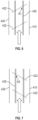
FIG. 6 is a schematic diagram illustrating an angling of the bypass flow channels ofFIGS. 4 and 5 in correspondence with rotation of the second rotor element in accordance with embodiments; -
FIG. 7 is a schematic diagram illustrating an angling of the bypass flow channels ofFIGS. 4 and 5 in opposition to rotation of the second rotor element in accordance with embodiments; -
FIG. 8 is a side schematic illustration of first and second rotor elements, a piston seal ring and bypass flow channels formed through a body of the second rotor element in accordance with embodiments; and -
FIG. 9 is a cross-sectional view of first and second rotor elements, a piston seal ring and bypass flow channels formed through the body of the second rotor element taken along line 9-9 ofFIG. 8 in accordance with embodiments. - These and other advantages and features will become more apparent from the following description taken in conjunction with the drawings.
- A detailed description of one or more embodiments of the disclosed apparatus and method are presented herein by way of exemplification and not limitation with reference to the Figures.
-
FIG. 1 schematically illustrates agas turbine engine 20. Thegas turbine engine 20 is disclosed herein as a two-spool turbofan that generally incorporates afan section 22, acompressor section 24, acombustor section 26 and aturbine section 28. Alternative engines might include other systems or features. Thefan section 22 drives air along a bypass flow path B in a bypass duct, while thecompressor section 24 drives air along a core flow path C for compression and communication into thecombustor section 26 and then expansion through theturbine section 28. Although depicted as a two-spool turbofan gas turbine engine in the disclosed non-limiting embodiment, it should be understood that the concepts described herein are not limited to use with two-spool turbofans as the teachings may be applied to other types of turbine engines including three-spool architectures. - The exemplary
gas turbine engine 20 generally includes alow speed spool 30 and ahigh speed spool 32 mounted for rotation about an engine central longitudinal axis A relative to an enginestatic structure 36 viaseveral bearing systems 38. It should be understood thatvarious bearing systems 38 at various locations may alternatively or additionally be provided, and the location ofbearing systems 38 may be varied as appropriate to the application. - The
low speed spool 30 generally includes aninner shaft 40 that interconnects afan 42, alow pressure compressor 44 and alow pressure turbine 46. Theinner shaft 40 is connected to thefan 42 through a speed change mechanism, which in exemplarygas turbine engine 20 is illustrated as a gearedarchitecture 48 to drive thefan 42 at a lower speed than thelow speed spool 30. Thehigh speed spool 32 includes anouter shaft 50 that interconnects ahigh pressure compressor 52 andhigh pressure turbine 54. Acombustor 56 is arranged in thegas turbine engine 20 between thehigh pressure compressor 52 and thehigh pressure turbine 54. The enginestatic structure 36 is arranged generally between thehigh pressure turbine 54 and thelow pressure turbine 46. The enginestatic structure 36 further supports thebearing systems 38 in theturbine section 28. Theinner shaft 40 and theouter shaft 50 are concentric and rotate viabearing systems 38 about the engine central longitudinal axis A which is collinear with their longitudinal axes. - The core airflow is compressed by the
low pressure compressor 44 and then thehigh pressure compressor 52, is mixed and burned with fuel in thecombustor 56 and is then expanded over thehigh pressure turbine 54 and thelow pressure turbine 46. The high andlow pressure turbines low speed spool 30 and thehigh speed spool 32, respectively, in response to the expansion. It will be appreciated that each of the positions of thefan section 22,compressor section 24,combustor section 26,turbine section 28, and fandrive gear system 48 may be varied. For example, gearedarchitecture 48 may be located aft of thecombustor section 26 or even aft of theturbine section 28, and thefan section 22 may be positioned forward or aft of the location of gearedarchitecture 48. - With reference to
FIGS. 2 and3 , a piston seal ring (PSR) 201 is provided for use in thegas turbine engine 20 ofFIG. 1 in at least thecompressor section 24. ThePSR 201 can be formed as a split ring seal having a firstcircumferential end 210, a secondcircumferential end 211, an interior facing inner diameter (ID)surface 220, an exterior facing outer diameter (OD)surface 222, a firstaxial end face 230 and a secondaxial end face 231. ThePSR 201 has a nominal central longitudinal axis (centerline) 202 that is shared with the members it seals when in a nominally centered condition. The firstcircumferential end 210 and the secondcircumferential end 211 form a joint or junction 240 (seeFIG. 3 ). Thejoint orjunction 240 can be provided as a shiplap joint with a projectingportion 241 of the firstcircumferential end 210 being received by arebate 242 of the secondcircumferential end 211 and a projectingportion 243 of the second circumferential 211 end being received by arebate 244 in the firstcircumferential end 210. The example projecting portions have mating faces/surfaces - PSRs, such as the
PSR 201 ofFIGS. 2 and3 , are often small in cross section and made of relatively soft material as compared to the surrounding hardware. In addition, PSRs are typically split for assembly purposes (i.e., the joint orjunction 240 ofFIGS. 2 and3 ) and therefore may have little or limited hoop strength. As such, the overlap at the split of the PSRs as well as manufacturing processes and operational loading and wear can cause the sealing surfaces of PSRs to have flatness and/or circularity errors that allow for local leakage. Often this leakage is non-axisymmetric. Such non-axisymmetric leakage leads to local thermal hotspots on the surrounding hardware that can, in turn, lead to non-axisymmetric distortion of the surrounding hardware resulting in mass unbalance, localized stress concentrations and reduced sealing performance. - Therefore, as will be described below, bypass flows are implemented evenly around the hardware surrounding the PSR. The bypass flows essentially trade some of the sealing effectiveness of the PSR for uniform thermal behavior. Moreover, the usage of the bypass flows in this manner avoids any need to form bypass slots or channels in the PSR, which is itself already thin, and allows for reduced structural risk in the PSR. The bypass flows can be formed as channels or slots in the surrounding hardware, such as the rotor bore and the tie shaft.
- With reference to
FIGS. 4 and 5 ,section 401 of a gas turbine engine, such as thecompression section 24 of thegas turbine engine 20 ofFIG. 1 , includes afirst rotor element 410 defining a continuous circumferential groove 411, asecond rotor element 420 that is disposed to rotate about thefirst rotor element 410 and aPSR 430. Thefirst rotor element 410 can be provided at least as atie shaft 412 or another similar feature and thesecond rotor element 420 can be provided at least as arotor bore 421 or another similar feature. As described above and as shown inFIGS. 2 and3 , thePSR 430 includes opposite ends (i.e., firstcircumferential end 210 and secondcircumferential end 211 ofFIG. 2 ), a joint at which the opposite ends register with each other (i.e., the joint orjunction 240 ofFIGS. 2 and3 ) and entirely smooth and continuous axial and radial surfaces extending between the opposite ends (i.e.,ID surface 220,OD surface 222, firstaxial end face 230 and secondaxial end face 231 ofFIG. 2 ). - The
PSR 430 is disposed in the continuous circumferential groove 411 to form a continuouscircumferential seal 431 between thefirst rotor element 410 and thesecond rotor element 420. Thesecond rotor element 420 is formed to definebypass flow channels 422 about thePSR 430 that extend between oppositeaxial sides PSR 430. In accordance with embodiments, thesecond rotor element 420 is formed to define thebypass flow channels 422 such that thebypass flow channels 422 form asymmetric leak path 440 across thePSR 430. - In some but not all cases, the
bypass flow channels 422 defined by thesecond rotor element 420 can be provided as first bypass flow channels whereas thefirst rotor element 410 can also be formed to define bypass flow channels 422' as second bypass flow channels. These bypass flow channels 422' would thus extend along an interior surface of thePSR 430 and as above would extend between the oppositeaxial sides PSR 430 to contribute to the formation of the symmetric leak path 440 (i.e., to form first and second symmetric leak paths). - As shown in
FIG. 4 , thebypass flow channels 422 can be configured such that they begin at afirst plenum 450 at an upstream side of thePSR 430 and terminate at asecond plenum 451 at a downstream side of thePSR 430. - As shown in
FIG. 5 , thebypass flow channels 422 are distributed substantially evenly about thePSR 430. In this way, while leakage across thePSR 430 can be non-axisymmetric, thebypass flow channels 422 form thesymmetric leak path 440 which is axi-symmetric. Moreover, the volume of the fluid moving through thebypass flow channels 422 can significantly exceed and effectively overwhelm the volume of non-axisymmetric leakage across thePSR 430. As a result, thermal responses of the hardware surrounding the PSR (i.e., thefirst rotor element 420 and the second rotor element 420) can be controlled in an axi-symmetric manner. - In accordance with further embodiments and as shown in
FIGS. 4 and 5 , thesecond rotor element 420 can include an interior facingsurface 423. In these or other cases, theinterior surface 423 of thesecond rotor element 420 can be formed to define each of thebypass flow channels 422 as a slot 501 (seeFIG. 5 ) that extends along theinterior facing surface 423 in an axial dimension and/or in an axial and a circumferential dimension. - With reference to
FIGS. 6 and 7 , thebypass flow channels 422 can be angled. As shown inFIG. 6 , thebypass flow channels 422 can be angled at angle A1 in correspondence with a direction of rotation of thesecond rotor element 420 to encourage and entrain flow through the bypass flow channels. As shown inFIG. 7 , thebypass flow channels 422 can be angled at angle A2 in opposition to the direction of rotation of thesecond rotor element 420. In accordance with embodiments, the angle A1 can be between 0° and 70° or, more narrowly, between 20° and 35° and the angle A2 can be between 0° and 70° or, more narrowly, between 20° and 35° (the angles A1 and A2 inFIGS. 6 and 7 are not drawn to scale). - With reference to
FIGS. 8 and 9 and in accordance with further alternative embodiments, thesecond rotor element 420 can include abody 424. In these or other cases, thebody 424 of thesecond rotor element 420 can be formed to define each of the bypass flow channels (i.e., each of thebypass flow channels 422 ofFIG. 4 ) as a through-hole 801 that extends through thebody 424. The through-holes as bypass flow channels of the embodiments ofFIGS. 8 and 9 are other otherwise configured similarly as described above and need not be re-described. - Benefits of the features described herein are the utilization of parts adjacent to a PSR to form bypass flows that essentially trade some of the sealing effectiveness of the PSR for uniform thermal behavior. The bypass flows reduce manufacturability difficulties and allow for reduced structural risk to the PSR by not having bypass slots or channels formed therein.
- The term "about" is intended to include the degree of error associated with measurement of the particular quantity based upon the equipment available at the time of filing the application.
- The terminology used herein is for the purpose of describing particular embodiments only and is not intended to be limiting of the present disclosure. As used herein, the singular forms "a", "an" and "the" are intended to include the plural forms as well, unless the context clearly indicates otherwise. It will be further understood that the terms "comprises" and/or "comprising," when used in this specification, specify the presence of stated features, integers, steps, operations, elements, and/or components, but do not preclude the presence or addition of one or more other features, integers, steps, operations, element components, and/or groups thereof.
- While the present disclosure has been described with reference to an exemplary embodiment or embodiments, it will be understood by those skilled in the art that various changes may be made and equivalents may be substituted for elements thereof without departing from the scope of the present disclosure. In addition, many modifications may be made to adapt a particular situation or material to the teachings of the present disclosure without departing from the essential scope thereof. Therefore, it is intended that the present disclosure not be limited to the particular embodiment disclosed as the best mode contemplated for carrying out this present disclosure, but that the present disclosure will include all embodiments falling within the scope of the claims.
Claims (12)
- A gas turbine engine (20), comprising:a first rotor element (410) defining a groove;a second rotor element (420) disposed to rotate about the first rotor element (410); anda piston seal ring (PSR) (201; 430) disposed in the groove to form a seal between the first rotor element (410) and the second rotor element (420),the second rotor element (420) being formed to define bypass flow channels (422; 801) about the PSR (201; 430) that extend between opposite axial sides (432, 433) of the PSR (201; 430).
- The gas turbine engine (20) according to claim 1, wherein the first rotor element (410) comprises at least a tie shaft (412) and the second rotor element (420) comprises at least a rotor bore (421).
- The gas turbine engine (20) according to claim 1 or 2, wherein the PSR (201; 430) comprises:opposite ends (210, 211);a joint (240) at which the opposite ends (210, 211) register with each other; andentirely smooth and continuous axial and radial surfaces (220, 222, 230, 231) extending between the opposite ends (210, 211).
- The gas turbine engine (20) according to claim 1, 2 or 3, wherein the bypass flow channels (422) are distributed evenly about the PSR (201; 430).
- The gas turbine engine (20) according to any preceding claim, wherein the bypass flow channels (422) begin at a first plenum (450) at an upstream side of the PSR (201; 430) and terminate at a second plenum (451) at a downstream side of the PSR (201; 430).
- The gas turbine engine (20) according to any preceding claim, wherein:the second rotor element (420) comprises an interior facing surface (423), andthe second rotor element (420) is formed to define each of the bypass flow channels as a slot (501) extending along the interior facing surface (423).
- The gas turbine engine (20) according to any of claims 1 to 5, wherein:the second rotor element (420) comprises a body (424), andthe second rotor element (420) is formed to define each of the bypass flow channels as a through-hole (801) extending through the body (424).
- The gas turbine engine (20) according to any preceding claim, wherein the bypass flow channels (422) are angled in correspondence with a direction of rotation of the second rotor element (420).
- The gas turbine engine (20) according to any of claims 1 to 7, wherein the bypass flow channels (422) are angled in opposition to a direction of rotation of the second rotor element (420).
- The gas turbine engine (20) of any preceding claim, wherein:
the bypass flow channels (422) form a symmetric leak path (440) across the PSR (201; 430). - The gas turbine engine (20) of any preceding claim, wherein:
the first rotor element (410) is formed to define second bypass flow channels (422') along an interior surface of the PSR (201; 430) that extend between the opposite axial sides (432, 433) of the PSR (201; 430). - The gas turbine engine (20) according to claim 11, wherein the first and second bypass flow channels (422) form first and second symmetric leak paths across the PSR (201; 430).
Applications Claiming Priority (1)
| Application Number | Priority Date | Filing Date | Title |
|---|---|---|---|
| US18/388,617 US12234733B1 (en) | 2023-11-10 | 2023-11-10 | Seal flow bypass |
Publications (1)
| Publication Number | Publication Date |
|---|---|
| EP4553273A1 true EP4553273A1 (en) | 2025-05-14 |
Family
ID=93463092
Family Applications (1)
| Application Number | Title | Priority Date | Filing Date |
|---|---|---|---|
| EP24212161.4A Pending EP4553273A1 (en) | 2023-11-10 | 2024-11-11 | Piston seal ring with flow bypass |
Country Status (2)
| Country | Link |
|---|---|
| US (1) | US12234733B1 (en) |
| EP (1) | EP4553273A1 (en) |
Families Citing this family (2)
| Publication number | Priority date | Publication date | Assignee | Title |
|---|---|---|---|---|
| EP4336017B1 (en) * | 2022-09-06 | 2025-10-29 | RTX Corporation | Piston seal ring |
| EP4411115A3 (en) * | 2023-01-31 | 2024-12-18 | RTX Corporation | Seal ring |
Citations (7)
| Publication number | Priority date | Publication date | Assignee | Title |
|---|---|---|---|---|
| US20130280028A1 (en) * | 2012-04-24 | 2013-10-24 | United Technologies Corporation | Thermal management system for a gas turbine engine |
| EP1820936B1 (en) * | 2006-02-15 | 2016-11-23 | Rolls-Royce plc | Gas turbine engine rotor ventilation arrangement |
| US10563672B2 (en) * | 2018-02-07 | 2020-02-18 | United Technologies Corporation | Gas turbine engine compressor |
| EP3191743B1 (en) * | 2014-09-08 | 2020-03-25 | Westport Power Inc. | Piston arrangement |
| US11542819B2 (en) * | 2021-02-17 | 2023-01-03 | Pratt & Whitney Canada Corp. | Split ring seal for gas turbine engine rotor |
| EP4257851A1 (en) * | 2022-04-06 | 2023-10-11 | Raytheon Technologies Corporation | Piston seal ring |
| EP4411115A2 (en) * | 2023-01-31 | 2024-08-07 | RTX Corporation | Seal ring |
Family Cites Families (5)
| Publication number | Priority date | Publication date | Assignee | Title |
|---|---|---|---|---|
| FR2603947B1 (en) * | 1986-09-17 | 1990-11-30 | Snecma | DEVICE FOR HOLDING A SEAL ON A SHAFT END AND TURBOMACHINE COMPRISING SAME |
| GB2264541A (en) * | 1992-02-29 | 1993-09-01 | Rolls Royce Plc | Improved sealing ring for gas turbine engines |
| US20120112415A1 (en) * | 2010-11-10 | 2012-05-10 | United Technologies Corporation | Rotating seal ring with targeted split surface orientation |
| US20150362463A1 (en) * | 2013-03-01 | 2015-12-17 | Kyocera Corporation | Sensor |
| US11028713B2 (en) | 2019-04-03 | 2021-06-08 | Raytheon Technologies Corporation | Rotating carbon piston ring seal |
-
2023
- 2023-11-10 US US18/388,617 patent/US12234733B1/en active Active
-
2024
- 2024-11-11 EP EP24212161.4A patent/EP4553273A1/en active Pending
Patent Citations (7)
| Publication number | Priority date | Publication date | Assignee | Title |
|---|---|---|---|---|
| EP1820936B1 (en) * | 2006-02-15 | 2016-11-23 | Rolls-Royce plc | Gas turbine engine rotor ventilation arrangement |
| US20130280028A1 (en) * | 2012-04-24 | 2013-10-24 | United Technologies Corporation | Thermal management system for a gas turbine engine |
| EP3191743B1 (en) * | 2014-09-08 | 2020-03-25 | Westport Power Inc. | Piston arrangement |
| US10563672B2 (en) * | 2018-02-07 | 2020-02-18 | United Technologies Corporation | Gas turbine engine compressor |
| US11542819B2 (en) * | 2021-02-17 | 2023-01-03 | Pratt & Whitney Canada Corp. | Split ring seal for gas turbine engine rotor |
| EP4257851A1 (en) * | 2022-04-06 | 2023-10-11 | Raytheon Technologies Corporation | Piston seal ring |
| EP4411115A2 (en) * | 2023-01-31 | 2024-08-07 | RTX Corporation | Seal ring |
Also Published As
| Publication number | Publication date |
|---|---|
| US12234733B1 (en) | 2025-02-25 |
Similar Documents
| Publication | Publication Date | Title |
|---|---|---|
| EP4553273A1 (en) | Piston seal ring with flow bypass | |
| US11840930B2 (en) | Component with feather seal slots for a gas turbine engine | |
| US20150285152A1 (en) | Gas turbine engine and seal assembly therefore | |
| US20160115813A1 (en) | Dual compliant seal | |
| US11506071B2 (en) | Piston ring shuttle carrier | |
| US10975713B2 (en) | Hydrostatic seal with aft tooth | |
| EP3789588B1 (en) | Hydrostatic seal aligned with rotor rotation | |
| EP3786418A1 (en) | Hydrostatic seal with seal stops | |
| US11193593B2 (en) | Hydrostatic seal | |
| US11674548B2 (en) | Low profile rotating bearing centering spring | |
| EP3296053B1 (en) | Triple-weld fitting | |
| US11629645B2 (en) | Hydrostatic seal with extended carrier arm | |
| EP3835606A1 (en) | Curved beam centering spring for a thrust bearing | |
| EP3760841B1 (en) | Multi-purpose anti-rotation lock pin | |
| EP3933170B1 (en) | Mid mount sleeve arrangement | |
| US20250163818A1 (en) | Piston ring seal | |
| US20240151152A1 (en) | Seal for gas turbine engine | |
| US20240344607A1 (en) | Piston ring with integrated anti-rotation feature | |
| US12392251B2 (en) | Diametrically expandable/collapsible piston seal | |
| US20250347368A1 (en) | Non rotating spacer for gas turbine engine | |
| EP4647582A1 (en) | Sleeve for serially-arranged seal elements | |
| US20250264030A1 (en) | O-ring for gas turbine engine | |
| US20250154877A1 (en) | Slider seal of gas turbine engine | |
| US11092038B2 (en) | Notched axial flange for a split case compressor |
Legal Events
| Date | Code | Title | Description |
|---|---|---|---|
| PUAI | Public reference made under article 153(3) epc to a published international application that has entered the european phase |
Free format text: ORIGINAL CODE: 0009012 |
|
| STAA | Information on the status of an ep patent application or granted ep patent |
Free format text: STATUS: THE APPLICATION HAS BEEN PUBLISHED |
|
| AK | Designated contracting states |
Kind code of ref document: A1 Designated state(s): AL AT BE BG CH CY CZ DE DK EE ES FI FR GB GR HR HU IE IS IT LI LT LU LV MC ME MK MT NL NO PL PT RO RS SE SI SK SM TR |
|
| STAA | Information on the status of an ep patent application or granted ep patent |
Free format text: STATUS: REQUEST FOR EXAMINATION WAS MADE |
|
| 17P | Request for examination filed |
Effective date: 20251114 |