EP4553262A1 - Vehicle door displacement system, vehicle, and method for operating a vehicle door displacement system - Google Patents
Vehicle door displacement system, vehicle, and method for operating a vehicle door displacement system Download PDFInfo
- Publication number
- EP4553262A1 EP4553262A1 EP23209474.8A EP23209474A EP4553262A1 EP 4553262 A1 EP4553262 A1 EP 4553262A1 EP 23209474 A EP23209474 A EP 23209474A EP 4553262 A1 EP4553262 A1 EP 4553262A1
- Authority
- EP
- European Patent Office
- Prior art keywords
- bar
- vehicle
- door position
- displacement
- door
- Prior art date
- Legal status (The legal status is an assumption and is not a legal conclusion. Google has not performed a legal analysis and makes no representation as to the accuracy of the status listed.)
- Withdrawn
Links
Images




Classifications
-
- E—FIXED CONSTRUCTIONS
- E05—LOCKS; KEYS; WINDOW OR DOOR FITTINGS; SAFES
- E05F—DEVICES FOR MOVING WINGS INTO OPEN OR CLOSED POSITION; CHECKS FOR WINGS; WING FITTINGS NOT OTHERWISE PROVIDED FOR, CONCERNED WITH THE FUNCTIONING OF THE WING
- E05F1/00—Closers or openers for wings, not otherwise provided for in this subclass
- E05F1/08—Closers or openers for wings, not otherwise provided for in this subclass spring-actuated, e.g. for horizontally sliding wings
- E05F1/10—Closers or openers for wings, not otherwise provided for in this subclass spring-actuated, e.g. for horizontally sliding wings for swinging wings, e.g. counterbalance
- E05F1/14—Closers or openers for wings, not otherwise provided for in this subclass spring-actuated, e.g. for horizontally sliding wings for swinging wings, e.g. counterbalance with double-acting springs, e.g. for closing and opening or checking and closing no material
-
- E—FIXED CONSTRUCTIONS
- E05—LOCKS; KEYS; WINDOW OR DOOR FITTINGS; SAFES
- E05D—HINGES OR SUSPENSION DEVICES FOR DOORS, WINDOWS OR WINGS
- E05D15/00—Suspension arrangements for wings
- E05D15/06—Suspension arrangements for wings for wings sliding horizontally more or less in their own plane
- E05D15/10—Suspension arrangements for wings for wings sliding horizontally more or less in their own plane movable out of one plane into a second parallel plane
- E05D15/1005—Suspension arrangements for wings for wings sliding horizontally more or less in their own plane movable out of one plane into a second parallel plane the wing being supported on arms movable in horizontal planes
- E05D15/101—Suspension arrangements for wings for wings sliding horizontally more or less in their own plane movable out of one plane into a second parallel plane the wing being supported on arms movable in horizontal planes specially adapted for vehicles
-
- E—FIXED CONSTRUCTIONS
- E05—LOCKS; KEYS; WINDOW OR DOOR FITTINGS; SAFES
- E05F—DEVICES FOR MOVING WINGS INTO OPEN OR CLOSED POSITION; CHECKS FOR WINGS; WING FITTINGS NOT OTHERWISE PROVIDED FOR, CONCERNED WITH THE FUNCTIONING OF THE WING
- E05F1/00—Closers or openers for wings, not otherwise provided for in this subclass
- E05F1/08—Closers or openers for wings, not otherwise provided for in this subclass spring-actuated, e.g. for horizontally sliding wings
- E05F1/10—Closers or openers for wings, not otherwise provided for in this subclass spring-actuated, e.g. for horizontally sliding wings for swinging wings, e.g. counterbalance
- E05F1/1041—Closers or openers for wings, not otherwise provided for in this subclass spring-actuated, e.g. for horizontally sliding wings for swinging wings, e.g. counterbalance with a coil spring perpendicular to the pivot axis
- E05F1/1066—Closers or openers for wings, not otherwise provided for in this subclass spring-actuated, e.g. for horizontally sliding wings for swinging wings, e.g. counterbalance with a coil spring perpendicular to the pivot axis with a traction spring
-
- E—FIXED CONSTRUCTIONS
- E05—LOCKS; KEYS; WINDOW OR DOOR FITTINGS; SAFES
- E05Y—INDEXING SCHEME ASSOCIATED WITH SUBCLASSES E05D AND E05F, RELATING TO CONSTRUCTION ELEMENTS, ELECTRIC CONTROL, POWER SUPPLY, POWER SIGNAL OR TRANSMISSION, USER INTERFACES, MOUNTING OR COUPLING, DETAILS, ACCESSORIES, AUXILIARY OPERATIONS NOT OTHERWISE PROVIDED FOR, APPLICATION THEREOF
- E05Y2201/00—Constructional elements; Accessories therefor
- E05Y2201/40—Motors; Magnets; Springs; Weights; Accessories therefor
- E05Y2201/404—Function thereof
- E05Y2201/41—Function thereof for closing
- E05Y2201/412—Function thereof for closing for the final closing movement
-
- E—FIXED CONSTRUCTIONS
- E05—LOCKS; KEYS; WINDOW OR DOOR FITTINGS; SAFES
- E05Y—INDEXING SCHEME ASSOCIATED WITH SUBCLASSES E05D AND E05F, RELATING TO CONSTRUCTION ELEMENTS, ELECTRIC CONTROL, POWER SUPPLY, POWER SIGNAL OR TRANSMISSION, USER INTERFACES, MOUNTING OR COUPLING, DETAILS, ACCESSORIES, AUXILIARY OPERATIONS NOT OTHERWISE PROVIDED FOR, APPLICATION THEREOF
- E05Y2201/00—Constructional elements; Accessories therefor
- E05Y2201/40—Motors; Magnets; Springs; Weights; Accessories therefor
- E05Y2201/404—Function thereof
- E05Y2201/422—Function thereof for opening
- E05Y2201/424—Function thereof for opening for the final opening movement
-
- E—FIXED CONSTRUCTIONS
- E05—LOCKS; KEYS; WINDOW OR DOOR FITTINGS; SAFES
- E05Y—INDEXING SCHEME ASSOCIATED WITH SUBCLASSES E05D AND E05F, RELATING TO CONSTRUCTION ELEMENTS, ELECTRIC CONTROL, POWER SUPPLY, POWER SIGNAL OR TRANSMISSION, USER INTERFACES, MOUNTING OR COUPLING, DETAILS, ACCESSORIES, AUXILIARY OPERATIONS NOT OTHERWISE PROVIDED FOR, APPLICATION THEREOF
- E05Y2201/00—Constructional elements; Accessories therefor
- E05Y2201/60—Suspension or transmission members; Accessories therefor
- E05Y2201/622—Suspension or transmission members elements
- E05Y2201/624—Arms
-
- E—FIXED CONSTRUCTIONS
- E05—LOCKS; KEYS; WINDOW OR DOOR FITTINGS; SAFES
- E05Y—INDEXING SCHEME ASSOCIATED WITH SUBCLASSES E05D AND E05F, RELATING TO CONSTRUCTION ELEMENTS, ELECTRIC CONTROL, POWER SUPPLY, POWER SIGNAL OR TRANSMISSION, USER INTERFACES, MOUNTING OR COUPLING, DETAILS, ACCESSORIES, AUXILIARY OPERATIONS NOT OTHERWISE PROVIDED FOR, APPLICATION THEREOF
- E05Y2201/00—Constructional elements; Accessories therefor
- E05Y2201/60—Suspension or transmission members; Accessories therefor
- E05Y2201/622—Suspension or transmission members elements
- E05Y2201/624—Arms
- E05Y2201/626—Levers
-
- E—FIXED CONSTRUCTIONS
- E05—LOCKS; KEYS; WINDOW OR DOOR FITTINGS; SAFES
- E05Y—INDEXING SCHEME ASSOCIATED WITH SUBCLASSES E05D AND E05F, RELATING TO CONSTRUCTION ELEMENTS, ELECTRIC CONTROL, POWER SUPPLY, POWER SIGNAL OR TRANSMISSION, USER INTERFACES, MOUNTING OR COUPLING, DETAILS, ACCESSORIES, AUXILIARY OPERATIONS NOT OTHERWISE PROVIDED FOR, APPLICATION THEREOF
- E05Y2900/00—Application of doors, windows, wings or fittings thereof
- E05Y2900/50—Application of doors, windows, wings or fittings thereof for vehicles
- E05Y2900/53—Type of wing
- E05Y2900/531—Doors
Definitions
- the present disclosure relates to a vehicle door displacement system comprising a displacement mechanism and an arm structure.
- the arm structure is arranged between a vehicle body structure and a vehicle door.
- the arm structure is pivotably connected to the vehicle body structure at an inner arm end and pivotably connected to the vehicle door at an outer arm end.
- the arm structure is configured for displacing the vehicle door between a closed door position and open door positions.
- the disclosure further relates to a vehicle comprising a vehicle door displacement system and a method for operating a vehicle door displacement system.
- Vehicle door systems are used for covering an opening of a vehicle body structure, where the opening leads to an interior compartment of the vehicle.
- the door systems generally comprise a vehicle door displacement mechanism used for displacing a vehicle door relative to the opening between a closed door position and open door positions.
- hinged vehicle doors are used, where the vehicle doors are connected to the vehicle body structure via hinges or similar arrangements, and displaced in relation to the vehicle body structure between open and closed positions by a swinging movement.
- Traditional hinged door systems are simple in construction but require a relatively large space outside the vehicle when being fully opened.
- Sliding vehicle doors are becoming more popular and are instead mounted to or suspended in relation to the vehicle body structure via a track system, or a combined track and hinge system.
- the sliding vehicle doors are displaced in relation to the vehicle body structure between open and closed positions, by a sliding movement horizontally alongside the vehicle body structure.
- Sliding door systems and other alternative door systems have the advantage with smaller space needed for the opening and closing of the door compared to a hinged door solution.
- Current sliding door system solutions commonly use a mechanism in the sill area, which increases the height of the sill so that the step-over height for entering the interior compartment of the vehicle is higher than that of traditional hinged door systems. There is further a problem with sliding doors in that the sliding movement of the door is restricted by the mechanism.
- Vehicle doors that are connected to the vehicle body structure with arms may be used as an alternative to sliding doors, where the arms are moved relative to the vehicle doors and the vehicle body structure upon displacement of the vehicle door between the closed and open door positions.
- movable arms there may be issues with efficient opening and closing of the vehicle doors, with a need for adding opening or closing forces during door opening and door closing operations, due to door displacement kinematics and weak geometries. Such added forces may cause stress on electric motors used for opening or closing the vehicle doors, or cause inefficient handling of the vehicle doors if opened or closed manually.
- gas springs are used for supporting a final door closing operation in the end of a door closing cycle. A problem with using a gas springs is that the force from the gas springs needs to be overcome when opening the vehicle doors.
- An object of the present disclosure is to provide a vehicle door displacement system, a vehicle comprising a vehicle door displacement system, and a method for operating a vehicle door displacement system, where the previously mentioned problems are avoided.
- This object is at least partly achieved by the features of the independent claims.
- the dependent claims contain further developments of the vehicle door displacement system and the method for operating a vehicle door displacement system.
- the disclosure concerns a vehicle door displacement system comprising a displacement mechanism and an arm structure.
- the arm structure is configured to be arranged between a vehicle body structure and a vehicle door.
- the arm structure is configured to be pivotably connected to the vehicle body structure at an inner arm end and the arm structure is configured to be pivotably connected to the vehicle door at an outer arm end.
- the arm structure is configured for displacing the vehicle door between a closed door position and an open door position.
- the displacement mechanism comprises a first bar and a second bar pivotably connected to each other via a bar pivot point.
- the first bar is pivotably connected to the arm structure and the second bar is configured to be pivotably connected to the vehicle body structure.
- the displacement mechanism further comprises a spring extending between the inner arm end and the first bar.
- the spring is configured for exerting an opening force onto the arm structure when the vehicle door is displaced from the closed door position to the open door position and a closing force onto the arm structure when the vehicle door is displaced from the open door position to the closed door position.
- the vehicle door displacement system is supporting efficient opening and closing of the vehicle door, by applying the opening and closing forces during door opening and door closing operations.
- the forces are in this way supporting the opening and closing operations even for weak geometries, and may relieve stress on electric motors used for opening or closing the vehicle door.
- the first bar and the second bar are through the pivoting displacements in the first bending direction and second bending direction respectively providing an efficient door operation, where the spring is exerting the opening force onto the arm structure when the vehicle door is displaced from the closed door position to the open door position and exerting the closing force onto the arm structure when the vehicle door is displaced from the open door position to the closed door position.
- the vehicle door displacement system is enabling efficient door opening and closing operations with a robust and reliable door displacement functionality.
- a first inner side of the first bar and a second inner side of the second bar are pivoted towards each other around the bar pivot point in the first bending direction.
- the first inner side and the second inner side are pivoted away from each other around the bar pivot point in the first bending direction.
- the first bending direction is defined as positions of the first bar and the second bar relative to each other, where the first inner side and the second inner side are arranged towards each other. In the first bending direction, the first bar and the second bar are pivoted such that the first inner side and the second inner side are facing each other.
- a first outer side of the first bar and a second outer side of the second bar are pivoted towards each other around the bar pivot point in the second bending direction.
- the first outer side and the second outer side are pivoted away from each other around the bar pivot point in the second bending direction.
- the second bending direction is defined as positions of the first bar and the second bar relative to each other, where instead the first outer side and the second outer side are arranged towards each other. In the second bending direction, the first bar and the second bar are pivoted such that the first outer side and the second outer side are facing each other.
- the arm structure is pivotably connected to the vehicle body structure at the inner arm end via an inner arm pivot point.
- the inner arm pivot point is used for an efficient displacement of the arm structure.
- a first outer end of the first bar is pivotably connected to the inner arm end of the arm structure via an outer bar pivot point.
- a first inner end of the first bar is pivotably connected to the second bar via the bar pivot point.
- a second outer end of the second bar is pivotably connected to the first bar via the bar pivot point.
- a second inner end of the second bar is pivotably connected to the vehicle body structure via an inner bar pivot point.
- the respective pivot points are connecting the first bar and the second bar to each other, the first bar to the arm structure, and the second bar to the vehicle body structure, for an efficient operation of the displacement mechanism.
- the inner arm end of the the arm structure comprises a first extending portion.
- the first extending portion is configured for extending in an inwards direction from the inner arm end towards an inner side of the vehicle when the vehicle door is arranged in the closed door position.
- the outer bar pivot point is arranged on the first extending portion spaced apart from the inner arm pivot point.
- the first extending portion is providing a suitable geometry for the vehicle door displacement system.
- the inner arm end of the the arm structure comprises a second extending portion.
- the second extending portion is configured for extending in an outwards direction from the inner arm end towards an outer side of the vehicle when the vehicle door is arranged in the closed door position.
- the spring is attached to the second extending portion.
- the second extending portion is providing an efficient positioning of the spring relative to the first bar during the door opening and closing operations.
- first extending portion and the second extending portion are arranged on a common bracket structure attached to and forming part of the arm structure.
- the common bracket structure is simplifying the construction of the vehicle door displacement system.
- the arm structure is configured to pivot relative to the vehicle body structure and the vehicle door when displacing the vehicle door between the closed door position and the open door position.
- the first bar is configured for pivoting relative to the arm structure and the second bar
- the second bar is configured for pivoting relative to the vehicle body structure and the first bar. The pivoting movements are supporting the exerting of the opening and closing forces.
- the spring is arranged as a coil spring configured for exerting an opening force onto the arm structure when the vehicle door is displaced from the closed door position to the open door position, and exerting a closing force onto the arm structure when the vehicle door is displaced from the open door position to the closed door position.
- the coil spring is providing a simple and reliable spring configuration.
- the disclosure further concerns a vehicle comprising a vehicle door displacement system as described above.
- the disclosure further concerns a method for operating a vehicle door displacement system comprising a displacement mechanism and an arm structure.
- the arm structure is arranged between a vehicle body structure and a vehicle door.
- the arm structure is pivotably connected to the vehicle body structure at an inner arm end and pivotably connected to the vehicle door at an outer arm end.
- the arm structure is configured for displacing the vehicle door between a closed door position and an open door position.
- the displacement mechanism comprises a first bar and a second bar pivotably connected to each other via a bar pivot point.
- the first bar is pivotably connected to the arm structure and the second bar is pivotably connected to the vehicle body structure.
- the displacement mechanism further comprises a spring extending between the inner arm end and the first bar.
- the method comprises the steps: pivoting the first bar and the second bar relative to each other around the bar pivot point in a first bending direction during displacement of the vehicle door from the closed door position to the open door, and exerting an opening force onto the arm structure by the spring when the vehicle door is displaced from the closed door position to the open door position; pivoting the first bar and the second bar relative to each other around the bar pivot point in a second bending direction opposite the first bending direction during displacement of the vehicle door from the open door position to the closed door position, and exerting a closing force onto the arm structure by the spring when the vehicle door is displaced from the open door position to the closed door position.
- the method for operating the vehicle door displacement system is supporting efficient opening and closing of the vehicle door, by applying the opening and closing forces during door opening and door closing operations.
- the forces are in this way efficiently supporting the opening and closing operations even for weak geometries, and may relieve stress on electric motors used for opening or closing the vehicle door.
- the first bar and the second bar are through the pivoting displacements in the first bending direction and second bending direction respectively providing an efficient door operation, where the spring is exerting the opening force onto the arm structure when the vehicle door is displaced from the closed door position to the open door position and exerting the closing force onto the arm structure when the vehicle door is displaced from the open door position to the closed door position.
- the method is enabling efficient door opening and closing operations with a robust and reliable door displacement functionality.
- the method further comprises the steps: pivoting a first inner side of the first bar and a second inner side of the second bar towards each other around the bar pivot point in the first bending direction during an initial opening displacement from the closed door position to the open door position; and pivoting the first inner side and the second inner side away from each other around the bar pivot point in the first bending direction during a final opening displacement.
- the first bending direction is defined as positions of the first bar and the second bar relative to each other, where the first inner side and the second inner side are arranged towards each other. In the first bending direction, the first bar and the second bar are pivoted such that the first inner side and the second inner side are facing each other.
- the method further comprises the steps: pivoting a first outer side of the first bar and a second outer side of the second bar towards each other around the bar pivot point in the second bending direction during an initial closing displacement from the open door position to the closed door position; and pivoting the first outer side and the second outer side away from each other around the bar pivot point in the second bending direction during a final closing displacement.
- the second bending direction is defined as positions of the first bar and the second bar relative to each other, where instead the first outer side and the second outer side are arranged towards each other. In the second bending direction, the first bar and the second bar are pivoted such that the first outer side and the second outer side are facing each other.
- the spring is exerting the opening force onto the arm structure during the initial opening displacement and/or the final opening displacement, and/or the spring is exerting the closing force onto the arm structure during the initial closing displacement and/or the final closing displacement. In this way, the spring is efficiently applying the opening and closing forces.
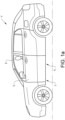
- FIGS 1a-b schematically show a vehicle V comprising a vehicle door displacement system S.
- the vehicle V comprises vehicle doors D movably arranged relative to a vehicle body structure B of the vehicle V.
- the vehicle door displacement system S will be described in connection to a vehicle door D arranged as a front side door of the vehicle V, as illustrated in the figures. It should however be understood that the configuration of the vehicle door D may be applicable on other door structures of the vehicle V, such as a vehicle door D arranged as a rear side door.
- the vehicle door D is arranged in a closed door position Pc, and in figure 1b , the vehicle door D is arranged in an open door position Po.
- the vehicle door D is movably arranged relative to the vehicle body structure B between the closed door position Pc and open door positions Po. Any position in which the vehicle door D has been displaced away from the closed door position P C may be considered an open door position P O , such as a partly open door position or a fully open door position.
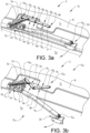
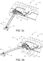
- a closed door position P C of the vehicle door D is schematically shown in figures 3a and 3i , partly open door positions P OP of the vehicle door D during a door opening operation are schematically shown in figures 3b-d , a fully open door position P OF of the vehicle door D is schematically shown in figure 3e , and partly open door positions P OP of the vehicle door D during a door closing operation are schematically shown in figures 3f-h .
- the vehicle door D is shown with dotted lines in figure 3a , but not shown in figures 3b-i for illustrative purposes.
- the vehicle door displacement system S comprises a displacement mechanism 1 and an arm structure 2.
- the arm structure 2 is arranged between the vehicle body structure B and the vehicle door D.
- the vehicle door D is connected to the vehicle body structure B via the arm structure 2, as shown in for example figure 2 .
- the vehicle door D is further connected to the vehicle body structure B via a supporting arm structure 20 for efficient displacement of the vehicle door D between the closed door position Pc and the fully open door position P OF .
- the arm structure 2 and the supporting arm structure 20 are arranged at a lower end D LE of the vehicle door D.
- the arm structure 2 and the supporting arm structure 20 are moved relative to the vehicle door D and the vehicle body structure B upon displacement of the vehicle door D between the closed door position Pc and the open door positions Po. In this way, the arm structure 2 and the supporting arm structure 20 are providing a simple and reliable opening and closing of the vehicle door D.
- the vehicle door D is arranged as a front side door in direct connection to a rear side door and the vehicle V may be arranged with a large door opening having no supporting B-pillar.
- arm structure 2 is arranged forwards of the supporting arm structure 20.
- the arm structure 2 may instead be arranged rearwards of the supporting arm structure 20.
- the arm structure 2 comprises an inner arm end 2a and an outer arm end 2b.
- the arm structure 2 is pivotably connected to the vehicle body structure B at the inner arm end 2a and pivotably connected to the vehicle door D at the outer arm end 2b, as shown in figure 2 .
- the arm structure 2 is in this way pivotably arranged relative to both the vehicle door D and the vehicle body structure B, and configured for displacing the vehicle door D between the closed door position Pc and an open door positions Po.
- the arm structure 2 is pivotably connected to the vehicle body structure B at the inner arm end 2a via an inner arm pivot point P A
- the arm structure 2 is pivotably connected to the vehicle door D at the outer arm end 2b via an outer arm pivot point P AO .
- the inner arm end 2a is pivotably connected to a side sill structure 9 forming part of the vehicle body structure B.
- the arm structure 2 is configured for pivoting around the inner arm pivot point P A and the outer arm pivot point P AO upon displacement of the vehicle door D between the closed door position Pc and the open door positions Po.
- the inner arm pivot point P A and the outer arm pivot point P AO are suitably arranged as shafts or axle structures around which the arm structure 2 is allowed to pivot upon displacement of the vehicle door D relative to the vehicle body structure B.
- the shafts or axle structures are suitably arranged in a holding structure or similar arrangement attached to the vehicle body structure B and the vehicle door D respectively.
- the supporting arm structure 20 comprises a second inner arm end 20a pivotably connected to the vehicle body structure B and a second outer arm end 20b pivotably connected to the vehicle door D, as shown in figure 2 .
- the supporting arm structure 20 is in this way pivotably arranged relative to both the vehicle door D and the vehicle body structure B.
- the second inner arm end 20a is pivotably connected to the vehicle body structure B via a second inner arm pivot point 20c and the second outer arm end 20b is pivotably connected to the vehicle door D via a second outer arm pivot point 20d.
- the second inner arm end 20a is pivotably connected to a side sill structure 9 forming part of the vehicle body structure B.
- the supporting arm structure 20 is configured for pivoting around the second inner arm pivot point 20c and the second outer arm pivot point 20d upon displacement of the vehicle door D between the closed door position Pc and the open door positions Po.
- the second inner arm pivot point 20c and the second outer arm pivot point 20d are suitably arranged as shafts or axle structures around which the supporting arm structure 20 is allowed to pivot upon displacement of the vehicle door D relative to the vehicle body structure B.
- the shafts or axle structures are suitably arranged in a holding structure or similar arrangement attached to the vehicle body structure B and the vehicle door D respectively.
- the displacement mechanism 1 is supporting the door opening and door closing operations by applying an opening force F O and a closing force F C respectively onto the arm structure 2.
- the displacement mechanism 1 comprises a first bar 1a and a second bar 1b pivotably connected to each other via a bar pivot point P B , as shown in figures 3a-i .
- the first bar 1a is pivotably connected to the arm structure 2 and the second bar 1b is pivotably connected to the vehicle body structure B.
- the displacement mechanism 1 further comprises a spring 10 extending between the inner arm end 2a of the arm structure 2 and the first bar 1a.
- the spring 10 is exerting the opening force Fo onto the arm structure 2 when the vehicle door D is displaced from the closed door position Pc to the open door position Po.
- the spring 10 is exerting the closing force Fc onto the arm structure 2 when the vehicle door D is displaced from the open door position Po to the closed door position Pc.
- the first bar 1a comprises a first inner side 3a and a first outer side 4a. As shown in figure 3a , the first inner side 3a is arranged towards an inner side S I of the vehicle V when the vehicle door D is arranged in the closed door position Pc, and the first outer side 4a is arranged towards an outer side So of the vehicle V when the vehicle door D is arranged in the closed door position Pc.
- the second bar 1b comprises a second inner side 3b and a second outer side 4b. As shown in figure 3a , the second inner side 3b is arranged towards the inner side S I of the vehicle V when the vehicle door D is arranged in the closed door position Pc, and the second outer side 4b is arranged towards an outer side So of the vehicle V when the vehicle door D is arranged in the closed door position Pc.
- the first inner side 3a and the second inner side 3b are typically arranged towards an interior structure of the vehicle V in the closed door position Pc, such as an interior compartment of the vehicle. In this way, the first inner side 3a and the second inner side 3b are facing the inner side S I of the vehicle V formed by the interior structure in the closed door position Pc.
- the first outer side 4a and the second outer side 4b are arranged towards the exterior outside the vehicle V in the closed door position Pc. In this way, the first outer side 4a and the second outer side 4b are facing the outer side So of the vehicle V, such as an outer side of the vehicle door D, as understood from figure 3a .
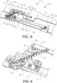
- a first outer end 5a of the first bar 1a is pivotably connected to the inner arm end 2a of the arm structure 2 via an outer bar pivot point P BO , as shown in figures 3a and 4 .
- a first inner end 6a of the first bar 1a is pivotably connected to the second bar 1b via the bar pivot point P B .
- a second outer end 5b of the second bar 1b is pivotably connected to the first bar 1a via the bar pivot point P B .
- a second inner end 6b of the second bar 1b is pivotably connected to the vehicle body structure B via an inner bar pivot point P BI .
- the spring 10 is connected to the first bar 1a at a suitable position between the bar pivot point P B and the outer bar pivot point P BO .
- the inner arm end 2a of the the arm structure 2 comprises a first extending portion 7a, and the first extending portion 7a is extending in an inwards direction from the inner arm end 2a towards an inner side S I of the vehicle when the vehicle door D is arranged in the closed door position Pc, as understood from figure 3a .
- the outer bar pivot point P BO is arranged on the first extending portion 7a spaced apart from the inner arm pivot point P A .
- the inner arm end 2a of the the arm structure 2 comprises a second extending portion 7b, and the second extending portion 7b is extending in an outwards direction from the inner arm end 2a towards the outer side So of the vehicle when the vehicle door D is arranged in the closed door position Pc, as understood from figure 3a .
- the spring 10 is attached to the second extending portion 7b, as shown in for example figure 4 .
- the first extending portion 7a and the second extending portion 7b are arranged on a common bracket structure 8 attached to and forming part of the arm structure 2.
- the arm structure 2 is pivoting relative to the vehicle body structure B and the vehicle door D when displacing the vehicle door D between the closed door position Pc and the open door position Po.
- the first bar 1a is pivoting relative to the arm structure 2 and the second bar 1b
- the second bar 1b is pivoting relative to the vehicle body structure B and the first bar 1a.
- the spring 10 is in the shown embodiment arranged as a coil spring.
- the spring 10 is exerting an opening force Fo onto the arm structure 2 when the vehicle door D is displaced from the closed door position Pc to the open door position Po.
- the spring 10 is exerting a closing force Fc onto the arm structure 2 when the vehicle door D is displaced from the open door position Po to the closed door position Pc.
- the spring 10 may have any other suitable configuration, such as other types of extension springs, or gas springs having similar characteristics.
- first bar 1a and the second bar 1b are pivoted relative to each other around the bar pivot point P B in a first bending direction D B1 , as will be described below in connection to figures 3a-e .
- the first bar 1a and the second bar 1b are pivoted relative to each other around the bar pivot point P B in a second bending direction D B2 opposite the first bending direction D B1 , as will be described below in connection to figures 3e-i .
- the first bending direction D B1 is defined as positions of the first bar 1a and the second bar 1b relative to each other, where the first inner side 3a and the second inner side 3b are arranged towards each other, as illustrated in figures 3b-d .
- the first bar 1a and the second bar 1b are pivoted such that the first inner side 3a and the second inner side 3b are facing each other, and such that that the first outer side 4a and the second outer side 4b are facing away from each other.
- the second bending direction D B2 is defined as positions of the first bar 1a and the second bar 1b relative to each other, where instead the first outer side 4a and the second outer side 4b are arranged towards each other, as illustrated in figures 3f-h .
- the first bar 1a and the second bar 1b are pivoted such that the first outer side 4a and the second outer side 4b are facing each other, and such that that the first inner side 3a and the second inner side 3b are facing away from each other.
- FIG. 3a A door opening operation from the closed door position P C to the fully open door position P OF is sequentially illustrated in figures 3a-e .
- the vehicle door D is arranged in the closed door position Pc
- the vehicle door is arranged in the fully open door position P OF .
- a door opening sequence is initiated.
- the first inner side 3a and the second inner side 3b are pivoted away from each other around the bar pivot point P B in the first bending direction D B1 , as shown with the arrows in figure 3d , and further pivoted away from each other to the fully open door position P OF shown in figure 3e .
- the first inner side 3a and the second inner side 3b are first pivoted towards each other around the bar pivot point P B in the first bending direction D B1 , and thereafter the first inner side 3a and the second inner side 3b are pivoted away from each other around the bar pivot point P B in the first bending direction D B1 .
- the specific angular position between the first bar 1a and the second bar 1b where the pivoting movement shift from pivoting towards each other to pivoting away from each other may depend on the specific geometry of the displacement mechanism 1 and the arm structure 2.
- a door closing operation from the fully open door position P OF to the closed door position Pc is sequentially illustrated in figures 3e-i .
- the vehicle door D is arranged in the fully open door position P OF
- the vehicle door is arranged in the closed door position Pc.
- first outer side 4a and the second outer side 4b are pivoted away from each other around the bar pivot point P B in the second bending direction D B2 , as shown with the arrows in figure 3h , and further pivoted away from each other to the closed door position P C shown in figure 3i .
- first outer side 4a and the second outer side 4b are first pivoted towards each other around the bar pivot point P B in the second bending direction D B2 , and thereafter the first outer side 4a and the second outer side 4b are pivoted away from each other around the bar pivot point P B in the second bending direction D B2 .
- the specific angular position between the first bar 1a and the second bar 1b where the pivoting movement shift from pivoting towards each other to pivoting away from each other may depend on the specific geometry of the displacement mechanism 1 and the arm structure 2.
- the vehicle door displacement system S is enabling efficient opening operations of the vehicle door D, by pivoting the first bar 1a and the second bar 1b relative to each other around the bar pivot point P B in the first bending direction D B1 during displacement of the vehicle door D from the closed door position Pc to the open door position Po, and exerting the opening force Fo onto the arm structure 2 by the spring 10 when the vehicle door D is displaced from the closed door position Pc to the open door position Po.
- the first inner side 3a of the first bar 1a and the second inner side 3b of the second bar 1b are pivoted towards each other around the bar pivot point P B in the first bending direction D B1 during the initial opening displacement D IO from the closed door position Pc to the open door position Po, and the first inner side 3a and the second inner side 3b are pivoted away from each other around the bar pivot point P B in the first bending direction D B1 during the final opening displacement D FO .
- the spring 10 is exerting the opening force Fo onto the arm structure 2 during the initial opening displacement D IO and/or the final opening displacement D IF .
- the vehicle door displacement system S is further enabling efficient closing operations of the vehicle door D, by pivoting the first bar 1a and the second bar 1b relative to each other around the bar pivot point P B in the second bending direction D B2 during displacement of the vehicle door D from the open door position Po to the closed door position P C , and exerting the closing force F C onto the arm structure 2 by the spring 10 when the vehicle door D is displaced from the open door position Po to the closed door position Pc.
- the first outer side 4a of the first bar 1a and the second outer side 4b of the second bar 1b are pivoted towards each other around the bar pivot point P B in the second bending direction D B2 during the initial closing displacement D IC from the open door position Po to the closed door position Pc, and the first outer side 4a and the second outer side 4b are pivoted away from each other around the bar pivot point P B in the second bending direction D B1 during the final closing displacement D FC .
- the spring 10 is exerting the closing force F C onto the arm structure 2 during the initial closing displacement D IC and/or the final closing displacement D FC .
- the displacement mechanism 1 with the first bar 1a and the second bar 1b described above is extending between the arm structure 2 and the vehicle body structure B, but the displacement mechanism 1 could also be mounted to extend between the arm structure 2 and the vehicle door D.
Landscapes
- Engineering & Computer Science (AREA)
- Mechanical Engineering (AREA)
- Support Devices For Sliding Doors (AREA)
Abstract
A vehicle door displacement system comprising a displacement mechanism and an arm structure. The arm structure is arranged between a vehicle body structure and a vehicle door. The arm structure is pivotably connected to the vehicle body structure at an inner arm end and pivotably connected to the vehicle door at an outer arm end. The arm structure is configured for displacing the vehicle door between a closed door position and an open door position. The displacement mechanism comprises a first bar and a second bar pivotably connected to each other via a bar pivot point. The first bar is pivotably connected to the arm structure and the second bar is pivotably connected to the vehicle body structure. The displacement mechanism further comprises a spring extending between the inner arm end and the first bar. The spring 3 is configured for exerting an opening force onto the arm structure when the vehicle door is displaced from the closed door position to the open door position and a closing force onto the arm structure when the vehicle door is displaced from the open door position to the closed door position. During displacement from the closed door position to the open door position, the first bar and the second bar are pivoted relative to each other around the bar pivot point in a first bending direction. During displacement from the open door position to the closed door position, the first bar and the second bar are pivoted relative to each other around the bar pivot point in a second bending direction opposite the first bending direction.
Description
- The present disclosure relates to a vehicle door displacement system comprising a displacement mechanism and an arm structure. The arm structure is arranged between a vehicle body structure and a vehicle door. The arm structure is pivotably connected to the vehicle body structure at an inner arm end and pivotably connected to the vehicle door at an outer arm end. The arm structure is configured for displacing the vehicle door between a closed door position and open door positions. The disclosure further relates to a vehicle comprising a vehicle door displacement system and a method for operating a vehicle door displacement system.
- Vehicle door systems are used for covering an opening of a vehicle body structure, where the opening leads to an interior compartment of the vehicle. The door systems generally comprise a vehicle door displacement mechanism used for displacing a vehicle door relative to the opening between a closed door position and open door positions.
- Traditionally, hinged vehicle doors are used, where the vehicle doors are connected to the vehicle body structure via hinges or similar arrangements, and displaced in relation to the vehicle body structure between open and closed positions by a swinging movement. Traditional hinged door systems are simple in construction but require a relatively large space outside the vehicle when being fully opened.
- Sliding vehicle doors are becoming more popular and are instead mounted to or suspended in relation to the vehicle body structure via a track system, or a combined track and hinge system. The sliding vehicle doors are displaced in relation to the vehicle body structure between open and closed positions, by a sliding movement horizontally alongside the vehicle body structure. Sliding door systems and other alternative door systems have the advantage with smaller space needed for the opening and closing of the door compared to a hinged door solution. Current sliding door system solutions commonly use a mechanism in the sill area, which increases the height of the sill so that the step-over height for entering the interior compartment of the vehicle is higher than that of traditional hinged door systems. There is further a problem with sliding doors in that the sliding movement of the door is restricted by the mechanism.
- Vehicle doors that are connected to the vehicle body structure with arms may be used as an alternative to sliding doors, where the arms are moved relative to the vehicle doors and the vehicle body structure upon displacement of the vehicle door between the closed and open door positions. When using movable arms, there may be issues with efficient opening and closing of the vehicle doors, with a need for adding opening or closing forces during door opening and door closing operations, due to door displacement kinematics and weak geometries. Such added forces may cause stress on electric motors used for opening or closing the vehicle doors, or cause inefficient handling of the vehicle doors if opened or closed manually. Sometimes gas springs are used for supporting a final door closing operation in the end of a door closing cycle. A problem with using a gas springs is that the force from the gas springs needs to be overcome when opening the vehicle doors.
- There is thus a need for an improved vehicle door displacement system having movable arms, where the vehicle doors can be efficiently opened and closed with a robust and reliable door displacement functionality.
- An object of the present disclosure is to provide a vehicle door displacement system, a vehicle comprising a vehicle door displacement system, and a method for operating a vehicle door displacement system, where the previously mentioned problems are avoided. This object is at least partly achieved by the features of the independent claims. The dependent claims contain further developments of the vehicle door displacement system and the method for operating a vehicle door displacement system.
- The disclosure concerns a vehicle door displacement system comprising a displacement mechanism and an arm structure. The arm structure is configured to be arranged between a vehicle body structure and a vehicle door. The arm structure is configured to be pivotably connected to the vehicle body structure at an inner arm end and the arm structure is configured to be pivotably connected to the vehicle door at an outer arm end. The arm structure is configured for displacing the vehicle door between a closed door position and an open door position. The displacement mechanism comprises a first bar and a second bar pivotably connected to each other via a bar pivot point. The first bar is pivotably connected to the arm structure and the second bar is configured to be pivotably connected to the vehicle body structure. The displacement mechanism further comprises a spring extending between the inner arm end and the first bar. The spring is configured for exerting an opening force onto the arm structure when the vehicle door is displaced from the closed door position to the open door position and a closing force onto the arm structure when the vehicle door is displaced from the open door position to the closed door position. During displacement from the closed door position to the open door position, the first bar and the second bar are pivoted relative to each other around the bar pivot point in a first bending direction. During displacement from the open door position to the closed door position, the first bar and the second bar are pivoted relative to each other around the bar pivot point in a second bending direction opposite the first bending direction.
- Advantages with these features are that the vehicle door displacement system is supporting efficient opening and closing of the vehicle door, by applying the opening and closing forces during door opening and door closing operations. The forces are in this way supporting the opening and closing operations even for weak geometries, and may relieve stress on electric motors used for opening or closing the vehicle door. The first bar and the second bar are through the pivoting displacements in the first bending direction and second bending direction respectively providing an efficient door operation, where the spring is exerting the opening force onto the arm structure when the vehicle door is displaced from the closed door position to the open door position and exerting the closing force onto the arm structure when the vehicle door is displaced from the open door position to the closed door position. The vehicle door displacement system is enabling efficient door opening and closing operations with a robust and reliable door displacement functionality.
- In one embodiment, during an initial opening displacement from the closed door position to the open door position, a first inner side of the first bar and a second inner side of the second bar are pivoted towards each other around the bar pivot point in the first bending direction. During a final opening displacement, the first inner side and the second inner side are pivoted away from each other around the bar pivot point in the first bending direction. The first bending direction is defined as positions of the first bar and the second bar relative to each other, where the first inner side and the second inner side are arranged towards each other. In the first bending direction, the first bar and the second bar are pivoted such that the first inner side and the second inner side are facing each other.
- In one embodiment, during an initial closing displacement from the open door position to the closed door position, a first outer side of the first bar and a second outer side of the second bar are pivoted towards each other around the bar pivot point in the second bending direction. During a final closing displacement, the first outer side and the second outer side are pivoted away from each other around the bar pivot point in the second bending direction. The second bending direction is defined as positions of the first bar and the second bar relative to each other, where instead the first outer side and the second outer side are arranged towards each other. In the second bending direction, the first bar and the second bar are pivoted such that the first outer side and the second outer side are facing each other.
- In one embodiment, the arm structure is pivotably connected to the vehicle body structure at the inner arm end via an inner arm pivot point. The inner arm pivot point is used for an efficient displacement of the arm structure.
- In one embodiment, a first outer end of the first bar is pivotably connected to the inner arm end of the arm structure via an outer bar pivot point. A first inner end of the first bar is pivotably connected to the second bar via the bar pivot point. A second outer end of the second bar is pivotably connected to the first bar via the bar pivot point. A second inner end of the second bar is pivotably connected to the vehicle body structure via an inner bar pivot point. The respective pivot points are connecting the first bar and the second bar to each other, the first bar to the arm structure, and the second bar to the vehicle body structure, for an efficient operation of the displacement mechanism.
- In one embodiment, the inner arm end of the the arm structure comprises a first extending portion. The first extending portion is configured for extending in an inwards direction from the inner arm end towards an inner side of the vehicle when the vehicle door is arranged in the closed door position. The outer bar pivot point is arranged on the first extending portion spaced apart from the inner arm pivot point. The first extending portion is providing a suitable geometry for the vehicle door displacement system.
- In one embodiment, the inner arm end of the the arm structure comprises a second extending portion. The second extending portion is configured for extending in an outwards direction from the inner arm end towards an outer side of the vehicle when the vehicle door is arranged in the closed door position. The spring is attached to the second extending portion. The second extending portion is providing an efficient positioning of the spring relative to the first bar during the door opening and closing operations.
- In one embodiment, the first extending portion and the second extending portion are arranged on a common bracket structure attached to and forming part of the arm structure. The common bracket structure is simplifying the construction of the vehicle door displacement system.
- In one embodiment, the arm structure is configured to pivot relative to the vehicle body structure and the vehicle door when displacing the vehicle door between the closed door position and the open door position. Upon pivoting movement of the arm structure relative to the vehicle body structure, the first bar is configured for pivoting relative to the arm structure and the second bar, and the second bar is configured for pivoting relative to the vehicle body structure and the first bar. The pivoting movements are supporting the exerting of the opening and closing forces.
- In one embodiment, the spring is arranged as a coil spring configured for exerting an opening force onto the arm structure when the vehicle door is displaced from the closed door position to the open door position, and exerting a closing force onto the arm structure when the vehicle door is displaced from the open door position to the closed door position. The coil spring is providing a simple and reliable spring configuration.
- The disclosure further concerns a vehicle comprising a vehicle door displacement system as described above.
- The disclosure further concerns a method for operating a vehicle door displacement system comprising a displacement mechanism and an arm structure. The arm structure is arranged between a vehicle body structure and a vehicle door. The arm structure is pivotably connected to the vehicle body structure at an inner arm end and pivotably connected to the vehicle door at an outer arm end. The arm structure is configured for displacing the vehicle door between a closed door position and an open door position. The displacement mechanism comprises a first bar and a second bar pivotably connected to each other via a bar pivot point. The first bar is pivotably connected to the arm structure and the second bar is pivotably connected to the vehicle body structure. The displacement mechanism further comprises a spring extending between the inner arm end and the first bar. The method comprises the steps: pivoting the first bar and the second bar relative to each other around the bar pivot point in a first bending direction during displacement of the vehicle door from the closed door position to the open door, and exerting an opening force onto the arm structure by the spring when the vehicle door is displaced from the closed door position to the open door position; pivoting the first bar and the second bar relative to each other around the bar pivot point in a second bending direction opposite the first bending direction during displacement of the vehicle door from the open door position to the closed door position, and exerting a closing force onto the arm structure by the spring when the vehicle door is displaced from the open door position to the closed door position.
- Advantages with these features are that the method for operating the vehicle door displacement system is supporting efficient opening and closing of the vehicle door, by applying the opening and closing forces during door opening and door closing operations. The forces are in this way efficiently supporting the opening and closing operations even for weak geometries, and may relieve stress on electric motors used for opening or closing the vehicle door. The first bar and the second bar are through the pivoting displacements in the first bending direction and second bending direction respectively providing an efficient door operation, where the spring is exerting the opening force onto the arm structure when the vehicle door is displaced from the closed door position to the open door position and exerting the closing force onto the arm structure when the vehicle door is displaced from the open door position to the closed door position. The method is enabling efficient door opening and closing operations with a robust and reliable door displacement functionality.
- In one embodiment, the method further comprises the steps: pivoting a first inner side of the first bar and a second inner side of the second bar towards each other around the bar pivot point in the first bending direction during an initial opening displacement from the closed door position to the open door position; and pivoting the first inner side and the second inner side away from each other around the bar pivot point in the first bending direction during a final opening displacement. The first bending direction is defined as positions of the first bar and the second bar relative to each other, where the first inner side and the second inner side are arranged towards each other. In the first bending direction, the first bar and the second bar are pivoted such that the first inner side and the second inner side are facing each other.
- In one embodiment, the method further comprises the steps: pivoting a first outer side of the first bar and a second outer side of the second bar towards each other around the bar pivot point in the second bending direction during an initial closing displacement from the open door position to the closed door position; and pivoting the first outer side and the second outer side away from each other around the bar pivot point in the second bending direction during a final closing displacement. The second bending direction is defined as positions of the first bar and the second bar relative to each other, where instead the first outer side and the second outer side are arranged towards each other. In the second bending direction, the first bar and the second bar are pivoted such that the first outer side and the second outer side are facing each other.
- In one embodiment, the spring is exerting the opening force onto the arm structure during the initial opening displacement and/or the final opening displacement, and/or the spring is exerting the closing force onto the arm structure during the initial closing displacement and/or the final closing displacement. In this way, the spring is efficiently applying the opening and closing forces.
- The disclosure will be described in detail in the following, with reference to the attached drawings, in which
- Fig. 1a-b
- show schematically, in side views, a vehicle having a vehicle door displacement system with a vehicle door arranged in a closed door position and in an open door position,
- Fig. 2
- shows schematically, in an inner side view, the vehicle door displacement system with the vehicle door arranged in the closed door position,
- Fig. 3a-i
- show schematically, in perspective views from above, the vehicle door displacement system in different operating positions, and
- Fig. 4
- shows schematically, in a perspective view from above, a section of the vehicle door displacement system.
- Various aspects of the disclosure will hereinafter be described in conjunction with the appended drawings to illustrate and not to limit the disclosure, wherein like designations denote like elements, and variations of the described aspects are not restricted to the specifically shown embodiments, but are applicable on other variations of the disclosure.
-
Figures 1a-b schematically show a vehicle V comprising a vehicle door displacement system S. The vehicle V comprises vehicle doors D movably arranged relative to a vehicle body structure B of the vehicle V. The vehicle door displacement system S will be described in connection to a vehicle door D arranged as a front side door of the vehicle V, as illustrated in the figures. It should however be understood that the configuration of the vehicle door D may be applicable on other door structures of the vehicle V, such as a vehicle door D arranged as a rear side door. - In
figure 1a , the vehicle door D is arranged in a closed door position Pc, and infigure 1b , the vehicle door D is arranged in an open door position Po. The vehicle door D is movably arranged relative to the vehicle body structure B between the closed door position Pc and open door positions Po. Any position in which the vehicle door D has been displaced away from the closed door position PC may be considered an open door position PO, such as a partly open door position or a fully open door position. A closed door position PC of the vehicle door D is schematically shown infigures 3a and3i , partly open door positions POP of the vehicle door D during a door opening operation are schematically shown infigures 3b-d , a fully open door position POF of the vehicle door D is schematically shown infigure 3e , and partly open door positions POP of the vehicle door D during a door closing operation are schematically shown infigures 3f-h . The vehicle door D is shown with dotted lines infigure 3a , but not shown infigures 3b-i for illustrative purposes. - The vehicle door displacement system S comprises a displacement mechanism 1 and an
arm structure 2. Thearm structure 2 is arranged between the vehicle body structure B and the vehicle door D. - The vehicle door D is connected to the vehicle body structure B via the
arm structure 2, as shown in for examplefigure 2 . In the shown embodiment, the vehicle door D is further connected to the vehicle body structure B via a supporting arm structure 20 for efficient displacement of the vehicle door D between the closed door position Pc and the fully open door position POF. Thearm structure 2 and the supporting arm structure 20 are arranged at a lower end DLE of the vehicle door D. Thearm structure 2 and the supporting arm structure 20 are moved relative to the vehicle door D and the vehicle body structure B upon displacement of the vehicle door D between the closed door position Pc and the open door positions Po. In this way, thearm structure 2 and the supporting arm structure 20 are providing a simple and reliable opening and closing of the vehicle door D. In the shown embodiment, the vehicle door D is arranged as a front side door in direct connection to a rear side door and the vehicle V may be arranged with a large door opening having no supporting B-pillar. - In the illustrated embodiment, where the vehicle door D is arranged as a front side door,
arm structure 2 is arranged forwards of the supporting arm structure 20. In other non-illustrated embodiments, thearm structure 2 may instead be arranged rearwards of the supporting arm structure 20. - The
arm structure 2 comprises aninner arm end 2a and anouter arm end 2b. Thearm structure 2 is pivotably connected to the vehicle body structure B at theinner arm end 2a and pivotably connected to the vehicle door D at theouter arm end 2b, as shown infigure 2 . Thearm structure 2 is in this way pivotably arranged relative to both the vehicle door D and the vehicle body structure B, and configured for displacing the vehicle door D between the closed door position Pc and an open door positions Po. Thearm structure 2 is pivotably connected to the vehicle body structure B at theinner arm end 2a via an inner arm pivot point PA, and thearm structure 2 is pivotably connected to the vehicle door D at theouter arm end 2b via an outer arm pivot point PAO. Suitably, theinner arm end 2a is pivotably connected to aside sill structure 9 forming part of the vehicle body structure B. Thearm structure 2 is configured for pivoting around the inner arm pivot point PA and the outer arm pivot point PAO upon displacement of the vehicle door D between the closed door position Pc and the open door positions Po. The inner arm pivot point PA and the outer arm pivot point PAO are suitably arranged as shafts or axle structures around which thearm structure 2 is allowed to pivot upon displacement of the vehicle door D relative to the vehicle body structure B. The shafts or axle structures are suitably arranged in a holding structure or similar arrangement attached to the vehicle body structure B and the vehicle door D respectively. - The supporting arm structure 20 comprises a second inner arm end 20a pivotably connected to the vehicle body structure B and a second
outer arm end 20b pivotably connected to the vehicle door D, as shown infigure 2 . The supporting arm structure 20 is in this way pivotably arranged relative to both the vehicle door D and the vehicle body structure B. The second inner arm end 20a is pivotably connected to the vehicle body structure B via a second innerarm pivot point 20c and the secondouter arm end 20b is pivotably connected to the vehicle door D via a second outerarm pivot point 20d. Suitably, the second inner arm end 20a is pivotably connected to aside sill structure 9 forming part of the vehicle body structure B. The supporting arm structure 20 is configured for pivoting around the second innerarm pivot point 20c and the second outerarm pivot point 20d upon displacement of the vehicle door D between the closed door position Pc and the open door positions Po. The second innerarm pivot point 20c and the second outerarm pivot point 20d are suitably arranged as shafts or axle structures around which the supporting arm structure 20 is allowed to pivot upon displacement of the vehicle door D relative to the vehicle body structure B. The shafts or axle structures are suitably arranged in a holding structure or similar arrangement attached to the vehicle body structure B and the vehicle door D respectively. - The displacement mechanism 1 is supporting the door opening and door closing operations by applying an opening force FO and a closing force FC respectively onto the
arm structure 2. The displacement mechanism 1 comprises afirst bar 1a and asecond bar 1b pivotably connected to each other via a bar pivot point PB, as shown infigures 3a-i . Thefirst bar 1a is pivotably connected to thearm structure 2 and thesecond bar 1b is pivotably connected to the vehicle body structure B. The displacement mechanism 1 further comprises aspring 10 extending between theinner arm end 2a of thearm structure 2 and thefirst bar 1a. Thespring 10 is exerting the opening force Fo onto thearm structure 2 when the vehicle door D is displaced from the closed door position Pc to the open door position Po. Thespring 10 is exerting the closing force Fc onto thearm structure 2 when the vehicle door D is displaced from the open door position Po to the closed door position Pc. - The
first bar 1a comprises a firstinner side 3a and a firstouter side 4a. As shown infigure 3a , the firstinner side 3a is arranged towards an inner side SI of the vehicle V when the vehicle door D is arranged in the closed door position Pc, and the firstouter side 4a is arranged towards an outer side So of the vehicle V when the vehicle door D is arranged in the closed door position Pc. - The
second bar 1b comprises a secondinner side 3b and a secondouter side 4b. As shown infigure 3a , the secondinner side 3b is arranged towards the inner side SI of the vehicle V when the vehicle door D is arranged in the closed door position Pc, and the secondouter side 4b is arranged towards an outer side So of the vehicle V when the vehicle door D is arranged in the closed door position Pc. - The first
inner side 3a and the secondinner side 3b are typically arranged towards an interior structure of the vehicle V in the closed door position Pc, such as an interior compartment of the vehicle. In this way, the firstinner side 3a and the secondinner side 3b are facing the inner side SI of the vehicle V formed by the interior structure in the closed door position Pc. The firstouter side 4a and the secondouter side 4b are arranged towards the exterior outside the vehicle V in the closed door position Pc. In this way, the firstouter side 4a and the secondouter side 4b are facing the outer side So of the vehicle V, such as an outer side of the vehicle door D, as understood fromfigure 3a . - A first
outer end 5a of thefirst bar 1a is pivotably connected to theinner arm end 2a of thearm structure 2 via an outer bar pivot point PBO, as shown infigures 3a and4 . A first inner end 6a of thefirst bar 1a is pivotably connected to thesecond bar 1b via the bar pivot point PB. A secondouter end 5b of thesecond bar 1b is pivotably connected to thefirst bar 1a via the bar pivot point PB. A second inner end 6b of thesecond bar 1b is pivotably connected to the vehicle body structure B via an inner bar pivot point PBI. Thespring 10 is connected to thefirst bar 1a at a suitable position between the bar pivot point PB and the outer bar pivot point PBO. - The
inner arm end 2a of the thearm structure 2 comprises a first extendingportion 7a, and the first extendingportion 7a is extending in an inwards direction from theinner arm end 2a towards an inner side SI of the vehicle when the vehicle door D is arranged in the closed door position Pc, as understood fromfigure 3a . The outer bar pivot point PBO is arranged on the first extendingportion 7a spaced apart from the inner arm pivot point PA. - The
inner arm end 2a of the thearm structure 2 comprises a second extendingportion 7b, and the second extendingportion 7b is extending in an outwards direction from theinner arm end 2a towards the outer side So of the vehicle when the vehicle door D is arranged in the closed door position Pc, as understood fromfigure 3a . Thespring 10 is attached to the second extendingportion 7b, as shown in for examplefigure 4 . - The first extending
portion 7a and the second extendingportion 7b are arranged on acommon bracket structure 8 attached to and forming part of thearm structure 2. - The
arm structure 2 is pivoting relative to the vehicle body structure B and the vehicle door D when displacing the vehicle door D between the closed door position Pc and the open door position Po. Upon pivoting movement of thearm structure 2 relative to the vehicle body structure B, thefirst bar 1a is pivoting relative to thearm structure 2 and thesecond bar 1b, and thesecond bar 1b is pivoting relative to the vehicle body structure B and thefirst bar 1a. - The
spring 10 is in the shown embodiment arranged as a coil spring. Thespring 10 is exerting an opening force Fo onto thearm structure 2 when the vehicle door D is displaced from the closed door position Pc to the open door position Po. Thespring 10 is exerting a closing force Fc onto thearm structure 2 when the vehicle door D is displaced from the open door position Po to the closed door position Pc. It should however be understood that thespring 10 may have any other suitable configuration, such as other types of extension springs, or gas springs having similar characteristics. - During a door opening sequence, where the vehicle door D is displaced from the closed door position Pc to the open door position Po, the
first bar 1a and thesecond bar 1b are pivoted relative to each other around the bar pivot point PB in a first bending direction DB1, as will be described below in connection tofigures 3a-e . - During a door closing sequence, where the vehicle door D is displaced from the open door position Po to the closed door position Pc, the
first bar 1a and thesecond bar 1b are pivoted relative to each other around the bar pivot point PB in a second bending direction DB2 opposite the first bending direction DB1, as will be described below in connection tofigures 3e-i . - The first bending direction DB1 is defined as positions of the
first bar 1a and thesecond bar 1b relative to each other, where the firstinner side 3a and the secondinner side 3b are arranged towards each other, as illustrated infigures 3b-d . In the first bending direction DB1, thefirst bar 1a and thesecond bar 1b are pivoted such that the firstinner side 3a and the secondinner side 3b are facing each other, and such that that the firstouter side 4a and the secondouter side 4b are facing away from each other. - The second bending direction DB2 is defined as positions of the
first bar 1a and thesecond bar 1b relative to each other, where instead the firstouter side 4a and the secondouter side 4b are arranged towards each other, as illustrated infigures 3f-h . In the second bending direction DB2, thefirst bar 1a and thesecond bar 1b are pivoted such that the firstouter side 4a and the secondouter side 4b are facing each other, and such that that the firstinner side 3a and the secondinner side 3b are facing away from each other. - A door opening operation from the closed door position PC to the fully open door position POF is sequentially illustrated in
figures 3a-e . Infigure 3a , the vehicle door D is arranged in the closed door position Pc, and infigure 3e , the vehicle door is arranged in the fully open door position POF. When the vehicle door D is opened from the closed door position Pc, a door opening sequence is initiated. - During an initial opening displacement DIO from the closed door position Pc towards the fully open door position POF, the first
inner side 3a of thefirst bar 1a and the secondinner side 3b of thesecond bar 1b are pivoted towards each other around the bar pivot point PB in the first bending direction DB1 through action from thespring 10, as illustrated with the arrows infigure 3b . Upon continued opening displacement of, the vehicle door D towards the fully open door position POF, the firstinner side 3a and the secondinner side 3b are further pivoted towards each other around the bar pivot point PB in the first bending direction DB1, as shown infigure 3c . During a final opening displacement DFO towards the fully open door position POF, the firstinner side 3a and the secondinner side 3b are pivoted away from each other around the bar pivot point PB in the first bending direction DB1, as shown with the arrows infigure 3d , and further pivoted away from each other to the fully open door position POF shown infigure 3e . Thus, during the door opening sequence, the firstinner side 3a and the secondinner side 3b are first pivoted towards each other around the bar pivot point PB in the first bending direction DB1, and thereafter the firstinner side 3a and the secondinner side 3b are pivoted away from each other around the bar pivot point PB in the first bending direction DB1. The specific angular position between thefirst bar 1a and thesecond bar 1b where the pivoting movement shift from pivoting towards each other to pivoting away from each other may depend on the specific geometry of the displacement mechanism 1 and thearm structure 2. - A door closing operation from the fully open door position POF to the closed door position Pc is sequentially illustrated in
figures 3e-i . Infigure 3e , the vehicle door D is arranged in the fully open door position POF, and infigure 3i , the vehicle door is arranged in the closed door position Pc. When the vehicle door D is closed from the fully open door position POF, a door closing sequence is initiated. - During an initial closing displacement DIC from the fully open door position POF to the closed door position Pc, the first
outer side 4a of thefirst bar 1a and the secondouter side 4b of thesecond bar 1b are pivoted towards each other around the bar pivot point PB in the second bending direction DB2 through action from thespring 10, as illustrated with the arrows infigure 3f . Upon continued closing displacement of the vehicle door D towards the closed door position Pc, the firstouter side 4a and the secondouter side 4b are further pivoted towards each other around the bar pivot point PB in the second bending direction DB2, as shown infigure 3g . During a final closing displacement DFC towards the closed door position Pc, the firstouter side 4a and the secondouter side 4b are pivoted away from each other around the bar pivot point PB in the second bending direction DB2, as shown with the arrows infigure 3h , and further pivoted away from each other to the closed door position PC shown infigure 3i . Thus, during the door closing sequence, the firstouter side 4a and the secondouter side 4b are first pivoted towards each other around the bar pivot point PB in the second bending direction DB2, and thereafter the firstouter side 4a and the secondouter side 4b are pivoted away from each other around the bar pivot point PB in the second bending direction DB2. The specific angular position between thefirst bar 1a and thesecond bar 1b where the pivoting movement shift from pivoting towards each other to pivoting away from each other may depend on the specific geometry of the displacement mechanism 1 and thearm structure 2. - The vehicle door displacement system S is enabling efficient opening operations of the vehicle door D, by pivoting the
first bar 1a and thesecond bar 1b relative to each other around the bar pivot point PB in the first bending direction DB1 during displacement of the vehicle door D from the closed door position Pc to the open door position Po, and exerting the opening force Fo onto thearm structure 2 by thespring 10 when the vehicle door D is displaced from the closed door position Pc to the open door position Po. The firstinner side 3a of thefirst bar 1a and the secondinner side 3b of thesecond bar 1b are pivoted towards each other around the bar pivot point PB in the first bending direction DB1 during the initial opening displacement DIO from the closed door position Pc to the open door position Po, and the firstinner side 3a and the secondinner side 3b are pivoted away from each other around the bar pivot point PB in the first bending direction DB1 during the final opening displacement DFO. Thespring 10 is exerting the opening force Fo onto thearm structure 2 during the initial opening displacement DIO and/or the final opening displacement DIF. - The vehicle door displacement system S is further enabling efficient closing operations of the vehicle door D, by pivoting the
first bar 1a and thesecond bar 1b relative to each other around the bar pivot point PB in the second bending direction DB2 during displacement of the vehicle door D from the open door position Po to the closed door position PC, and exerting the closing force FC onto thearm structure 2 by thespring 10 when the vehicle door D is displaced from the open door position Po to the closed door position Pc. The firstouter side 4a of thefirst bar 1a and the secondouter side 4b of thesecond bar 1b are pivoted towards each other around the bar pivot point PB in the second bending direction DB2 during the initial closing displacement DIC from the open door position Po to the closed door position Pc, and the firstouter side 4a and the secondouter side 4b are pivoted away from each other around the bar pivot point PB in the second bending direction DB1 during the final closing displacement DFC. Thespring 10 is exerting the closing force FC onto thearm structure 2 during the initial closing displacement DIC and/or the final closing displacement DFC. - The displacement mechanism 1 with the
first bar 1a and thesecond bar 1b described above is extending between thearm structure 2 and the vehicle body structure B, but the displacement mechanism 1 could also be mounted to extend between thearm structure 2 and the vehicle door D. - It will be appreciated that the above description is merely exemplary in nature and is not intended to limit the present disclosure, its application or uses. While specific examples have been described in the specification and illustrated in the drawings, it will be understood by those of ordinary skill in the art that various changes may be made and equivalents may be substituted for elements thereof without departing from the scope of the present disclosure as defined in the claims. Furthermore, modifications may be made to adapt a particular situation or material to the teachings of the present disclosure without departing from the essential scope thereof. Therefore, it is intended that the present disclosure not be limited to the particular examples illustrated by the drawings and described in the specification as the best mode presently contemplated for carrying out the teachings of the present disclosure, but that the scope of the present disclosure will include any embodiments falling within the foregoing description and the appended claims. Reference signs mentioned in the claims should not be seen as limiting the extent of the matter protected by the claims, and their sole function is to make claims easier to understand.
-
- 1:
- Displacement mechanism
- 1a:
- First bar
- 1b:
- Second bar
- 2:
- Arm structure
- 2a:
- Inner arm end
- 2b:
- Outer arm end
- 3a:
- First inner side, First bar
- 3b:
- Second inner side, Second bar
- 4a:
- First outer side, First bar
- 4a:
- Second outer side, Second bar
- 5a:
- First outer end, First bar
- 5b:
- Second outer end, Second bar
- 6a:
- First inner end, First bar
- 6b:
- Second inner end, Second bar
- 7a:
- First extending portion
- 7b:
- Second extending portion
- 8:
- Bracket structure
- 9:
- Side sill structure
- 10:
- Spring
- 20:
- Supporting arm structure
- 20a:
- Second inner arm end
- 20b:
- Second outer arm end
- 20c:
- Second inner arm pivot point
- 20d:
- Second outer arm pivot point
- B:
- Vehicle body structure
- D:
- Vehicle door
- DB1:
- First bending direction
- DB2:
- Second bending direction
- DIC:
- Initial closing displacement
- Dio:
- Initial opening displacement
- DFC:
- Final closing displacement
- DFO:
- Final opening displacement
- DLE:
- Lower end, Vehicle door
- PA:
- Inner arm pivot point
- PAO:
- Outer arm pivot point
- PB:
- Bar pivot point
- PBI:
- Inner bar pivot point
- PBO:
- Outer bar pivot point
- PC:
- Closed door position
- PO:
- Open door position
- POF:
- Fully open door position
- POP:
- Partly open door positions
- S:
- Vehicle door displacement system
- SI:
- Inner side
- So:
- Outer side
Claims (15)
- A vehicle door displacement system (S) comprising a displacement mechanism (1) and an arm structure (2), wherein the arm structure (2) is configured to be arranged between a vehicle body structure (B) and a vehicle door (D),wherein the arm structure (2) is configured to be pivotably connected to the vehicle body structure (B) at an inner arm end (2a) and pivotably connected to the vehicle door (D) at an outer arm end (2b), and configured for displacing the vehicle door (D) between a closed door position (Pc) and an open door position (Po),wherein the displacement mechanism (1) comprises a first bar (1a) and a second bar (1b) pivotably connected to each other via a bar pivot point (PB), wherein the first bar (1a) is pivotably connected to the arm structure (2) and the second bar (1b) is configured to be pivotably connected to the vehicle body structure (B),wherein the displacement mechanism (1) further comprises a spring (10) extending between the inner arm end (2a) and the first bar (1a), wherein the spring (10) is configured for exerting an opening force (Fo) onto the arm structure (2) when the vehicle door (D) is displaced from the closed door position (Pc) to the open door position (Po) and a closing force (Fc) onto the arm structure (2) when the vehicle door (D) is displaced from the open door position (Po) to the closed door position (Pc),wherein during displacement from the closed door position (Pc) to the open door position (Po), the first bar (1a) and the second bar (1b) are pivoted relative to each other around the bar pivot point (PB) in a first bending direction (DB1),wherein during displacement from the open door position (Po) to the closed door position (Pc), the first bar (1a) and the second bar (1b) are pivoted relative to each other around the bar pivot point (PB) in a second bending direction (DB2) opposite the first bending direction (DB1).
- The vehicle door displacement system (S) according to claim 1,
wherein during an initial opening displacement (Dio) from the closed door position (Pc) to the open door position (Po), a first inner side (3a) of the first bar (1a) and a second inner side (3b) of the second bar (1b) are pivoted towards each other around the bar pivot point (PB) in the first bending direction (DB1), and during a final opening displacement (DFO) the first inner side (3a) and the second inner side (3b) are pivoted away from each other around the bar pivot point (PB) in the first bending direction (DB1). - The vehicle door displacement system (S) according to claim 1 or 2,
wherein during an initial closing displacement (DIC) from the open door position (Po) to the closed door position (Pc), a first outer side (4a) of the first bar (1a) and a second outer side (4b) of the second bar (1b) are pivoted towards each other around the bar pivot point (PB) in the second bending direction (DB2), and during a final closing displacement (DFC) the first outer side (4a) and the second outer side (4b) are pivoted away from each other around the bar pivot point (PB) in the second bending direction (DB2). - The vehicle door displacement system (S) according to any preceding claim,
wherein the arm structure (2) is pivotably connected to the vehicle body structure (B) at the inner arm end (2a) via an inner arm pivot point (PA). - The vehicle door displacement system (S) according to any preceding claim,wherein a first outer end (5a) of the first bar (1a) is pivotably connected to the inner arm end (2a) of the arm structure (2) via an outer bar pivot point (Pso), wherein a first inner end (6a) of the first bar (1a) is pivotably connected to the second bar (1b) via the bar pivot point (PB),wherein a second outer end (5b) of the second bar (1b) is pivotably connected to the first bar (1a) via the bar pivot point (PB), wherein a second inner end (6b) of the second bar (1b) is pivotably connected to the vehicle body structure (B) via an inner bar pivot point (PBI).
- The vehicle door displacement system (S) according to claim 4 and 5,
wherein the inner arm end (2a) of the the arm structure (2) comprises a first extending portion (7a), wherein the first extending portion (7a) is configured for extending in an inwards direction from the inner arm end (2a) towards an inner side (SI) of the vehicle when the vehicle door (D) is arranged in the closed door position (PC), wherein the outer bar pivot point (PBO) is arranged on the first extending portion (7a) spaced apart from the inner arm pivot point (PA). - The vehicle door displacement system (S) according to any preceding claim,
Wherein the inner arm end (2a) of the the arm structure (2) comprises a second extending portion (7b), wherein the second extending portion (7b) is configured for extending in an outwards direction from the inner arm end (2a) towards an outer side (SO) of the vehicle when the vehicle door (D) is arranged in the closed door position (PC), wherein the spring (10) is attached to the second extending portion (7b). - The vehicle door displacement system (S) according to claim 6 or 7,
wherein the first extending portion (7a) and the second extending portion (7b) are arranged on a common bracket structure (8) attached to and forming part of the arm structure (2). - The vehicle door displacement system (S) according to any preceding claim,wherein the arm structure (2) is configured to pivot relative to the vehicle body structure (B) and the vehicle door (D) when displacing the vehicle door (D) between the closed door position (PC) and the open door position (PO),wherein upon pivoting movement of the arm structure (2) relative to the vehicle body structure (B), the first bar (1a) is configured for pivoting relative to the arm structure (2) and the second bar (1b), and the second bar (1b) is configured for pivoting relative to the vehicle body structure (B) and the first bar (1a).
- The vehicle door displacement system (S) according to any preceding claim,
wherein the spring (10) is arranged as a coil spring configured for exerting an opening force (Fo) onto the arm structure (2) when the vehicle door (D) is displaced from the closed door position (Pc) to the open door position (Po) and a closing force (Fc) onto the arm structure (2) when the vehicle door (D) is displaced from the open door position (Po) to the closed door position (Pc). - A vehicle comprising a vehicle door displacement system (S) according to any of claims 1 to 10.
- A method for operating a vehicle door displacement system (S) comprising a displacement mechanism (1) and an arm structure (2), wherein the arm structure (2) is arranged between a vehicle body structure (B) and a vehicle door (D),wherein the arm structure (2) is pivotably connected to the vehicle body structure (B) at an inner arm end (2a) and pivotably connected to the vehicle door (D) at an outer arm end (2b), and configured for displacing the vehicle door (D) between a closed door position (PC) and an open door position (PO),wherein the displacement mechanism (1) comprises a first bar (1a) and a second bar (1b) pivotably connected to each other via a bar pivot point (PB), wherein the first bar (1a) is pivotably connected to the arm structure (2) and the second bar (1b) is pivotably connected to the vehicle body structure (B),wherein the displacement mechanism (1) further comprises a spring (10) extending between the inner arm end (2a) and the first bar (1a), wherein the method comprises the steps:pivoting the first bar (1a) and the second bar (1b) relative to each other around the bar pivot point (PB) in a first bending direction (DB1) during displacement of the vehicle door (D) from the closed door position (PC) to the open door position (PO), and exerting an opening force (FO) onto the arm structure (2) by the spring (10) when the vehicle door (D) is displaced from the closed door position (PC) to the open door position (PO);pivoting the first bar (1a) and the second bar (1b) relative to each other around the bar pivot point (PB) in a second bending direction (DB2) opposite the first bending direction (DB1) during displacement of the vehicle door (D) from the open door position (PO) to the closed door position (PC), and exerting a closing force (FC) onto the arm structure (2) by the spring (10) when the vehicle door (D) is displaced from the open door position (PO) to the closed door position (PC).
- The method according to claim 12,
wherein the method further comprises the steps: pivoting a first inner side (3a) of the first bar (1a) and a second inner side (3b) of the second bar (1b) towards each other around the bar pivot point (PB) in the first bending direction (DB1) during an initial opening displacement (DIO) from the closed door position (PC) to the open door position (PO); and pivoting the first inner side (3a) and the second inner side (3b) away from each other around the bar pivot point (PB) in the first bending direction (DB1) during a final opening displacement (DFO). - The method according to claims 12 or 13,
wherein the method further comprises the steps: pivoting a first outer side (4a) of the first bar (1a) and a second outer side (4b) of the second bar (1b) towards each other around the bar pivot point (PB) in the second bending direction (DB2) during an initial closing displacement (DIC) from the open door position (Po) to the closed door position (PC); and pivoting the first outer side (4a) and the second outer side (4b) away from each other around the bar pivot point (PB) in the second bending direction (DB2) during a final closing displacement (DFC). - The method according to claim 13 or 14,wherein the spring (10) is exerting the opening force (FO) onto the arm structure (2) during the initial opening displacement (DIO) and/or the final opening displacement (DIF), and/orwherein the spring (10) is exerting the closing force (FC) onto the arm structure (2) during the initial closing displacement (DIC) and/or the final closing displacement (DFC).
Priority Applications (2)
| Application Number | Priority Date | Filing Date | Title |
|---|---|---|---|
| EP23209474.8A EP4553262A1 (en) | 2023-11-13 | 2023-11-13 | Vehicle door displacement system, vehicle, and method for operating a vehicle door displacement system |
| PCT/CN2024/131322 WO2025103269A1 (en) | 2023-11-13 | 2024-11-11 | Vehicle door displacement system, vehicle, and method for operating a vehicle door displacement system |
Applications Claiming Priority (1)
| Application Number | Priority Date | Filing Date | Title |
|---|---|---|---|
| EP23209474.8A EP4553262A1 (en) | 2023-11-13 | 2023-11-13 | Vehicle door displacement system, vehicle, and method for operating a vehicle door displacement system |
Publications (1)
| Publication Number | Publication Date |
|---|---|
| EP4553262A1 true EP4553262A1 (en) | 2025-05-14 |
Family
ID=88833699
Family Applications (1)
| Application Number | Title | Priority Date | Filing Date |
|---|---|---|---|
| EP23209474.8A Withdrawn EP4553262A1 (en) | 2023-11-13 | 2023-11-13 | Vehicle door displacement system, vehicle, and method for operating a vehicle door displacement system |
Country Status (2)
| Country | Link |
|---|---|
| EP (1) | EP4553262A1 (en) |
| WO (1) | WO2025103269A1 (en) |
Citations (3)
| Publication number | Priority date | Publication date | Assignee | Title |
|---|---|---|---|---|
| US2645810A (en) * | 1950-07-29 | 1953-07-21 | Ford Motor Co | Door checking and holding device |
| CN114382370A (en) * | 2022-01-17 | 2022-04-22 | 浙江极氪智能科技有限公司 | Frameless door opening mechanism and vehicle |
| US20230137554A1 (en) * | 2021-11-02 | 2023-05-04 | Aisin Corporation | Vehicle door device |
-
2023
- 2023-11-13 EP EP23209474.8A patent/EP4553262A1/en not_active Withdrawn
-
2024
- 2024-11-11 WO PCT/CN2024/131322 patent/WO2025103269A1/en active Pending
Patent Citations (3)
| Publication number | Priority date | Publication date | Assignee | Title |
|---|---|---|---|---|
| US2645810A (en) * | 1950-07-29 | 1953-07-21 | Ford Motor Co | Door checking and holding device |
| US20230137554A1 (en) * | 2021-11-02 | 2023-05-04 | Aisin Corporation | Vehicle door device |
| CN114382370A (en) * | 2022-01-17 | 2022-04-22 | 浙江极氪智能科技有限公司 | Frameless door opening mechanism and vehicle |
Also Published As
| Publication number | Publication date |
|---|---|
| WO2025103269A1 (en) | 2025-05-22 |
Similar Documents
| Publication | Publication Date | Title |
|---|---|---|
| US4143904A (en) | Station wagon tailgate | |
| US6325445B1 (en) | Motor vehicle with a body | |
| US20220185079A1 (en) | Vehicular door device | |
| CN112943020B (en) | Connecting rod structure for preventing swinging of split sliding door | |
| CN108966647B (en) | Arrangement with a cover for a vehicle roof | |
| EP1306512B1 (en) | An actuator assembly | |
| CN108590403B (en) | Scissor door hinge mechanism and vehicle | |
| KR890001798A (en) | Trunk Cover Hinges and Spring Assemblies | |
| JP3372533B2 (en) | Wing opening and closing device for trucks etc. | |
| EP4390032A1 (en) | Vehicle door system and method for operating a vehicle door system | |
| CN205153798U (en) | A closure member subassembly for vehicle | |
| JP2002067697A (en) | Flexural tail gate of automobile | |
| CN101512094A (en) | Furniture hinge | |
| CN116262433A (en) | Sliding door device for vehicle | |
| US11305707B2 (en) | Structure for shielding side sill for sliding door vehicle | |
| JPH1054172A (en) | Hinge device | |
| WO2025103269A1 (en) | Vehicle door displacement system, vehicle, and method for operating a vehicle door displacement system | |
| JPH0431423Y2 (en) | ||
| US6584647B2 (en) | Hinge for a motor vehicle rear door | |
| US6018912A (en) | Vehicle liftgate counter balance system | |
| CN116409122A (en) | Door device for vehicle | |
| US20030204995A1 (en) | Door opening/closing mechanism | |
| CN120042424A (en) | Door hinge device | |
| JP4045786B2 (en) | Vehicle door device | |
| DE102004033037B4 (en) | Hatch structure |
Legal Events
| Date | Code | Title | Description |
|---|---|---|---|
| PUAI | Public reference made under article 153(3) epc to a published international application that has entered the european phase |
Free format text: ORIGINAL CODE: 0009012 |
|
| STAA | Information on the status of an ep patent application or granted ep patent |
Free format text: STATUS: REQUEST FOR EXAMINATION WAS MADE |
|
| 17P | Request for examination filed |
Effective date: 20231113 |
|
| AK | Designated contracting states |
Kind code of ref document: A1 Designated state(s): AL AT BE BG CH CY CZ DE DK EE ES FI FR GB GR HR HU IE IS IT LI LT LU LV MC ME MK MT NL NO PL PT RO RS SE SI SK SM TR |
|
| STAA | Information on the status of an ep patent application or granted ep patent |
Free format text: STATUS: THE APPLICATION IS DEEMED TO BE WITHDRAWN |
|
| 18D | Application deemed to be withdrawn |
Effective date: 20251115 |