EP4553021A1 - Reel support device for double stacking configuration - Google Patents
Reel support device for double stacking configuration Download PDFInfo
- Publication number
- EP4553021A1 EP4553021A1 EP23209293.2A EP23209293A EP4553021A1 EP 4553021 A1 EP4553021 A1 EP 4553021A1 EP 23209293 A EP23209293 A EP 23209293A EP 4553021 A1 EP4553021 A1 EP 4553021A1
- Authority
- EP
- European Patent Office
- Prior art keywords
- support device
- receiving surface
- abutment
- labelling
- abutment surface
- Prior art date
- Legal status (The legal status is an assumption and is not a legal conclusion. Google has not performed a legal analysis and makes no representation as to the accuracy of the status listed.)
- Pending
Links
Images





Classifications
-
- B—PERFORMING OPERATIONS; TRANSPORTING
- B65—CONVEYING; PACKING; STORING; HANDLING THIN OR FILAMENTARY MATERIAL
- B65H—HANDLING THIN OR FILAMENTARY MATERIAL, e.g. SHEETS, WEBS, CABLES
- B65H19/00—Changing the web roll
- B65H19/10—Changing the web roll in unwinding mechanisms or in connection with unwinding operations
- B65H19/12—Lifting, transporting, or inserting the web roll; Removing empty core
- B65H19/123—Lifting, transporting, or inserting the web roll; Removing empty core with cantilever supporting arrangements
-
- B—PERFORMING OPERATIONS; TRANSPORTING
- B65—CONVEYING; PACKING; STORING; HANDLING THIN OR FILAMENTARY MATERIAL
- B65H—HANDLING THIN OR FILAMENTARY MATERIAL, e.g. SHEETS, WEBS, CABLES
- B65H2701/00—Handled material; Storage means
- B65H2701/50—Storage means for webs, tapes, or filamentary material
- B65H2701/53—Adaptations of cores or reels for special purposes
- B65H2701/534—Stackable or interlockable reels or parts of reels
-
- B—PERFORMING OPERATIONS; TRANSPORTING
- B65—CONVEYING; PACKING; STORING; HANDLING THIN OR FILAMENTARY MATERIAL
- B65H—HANDLING THIN OR FILAMENTARY MATERIAL, e.g. SHEETS, WEBS, CABLES
- B65H2801/00—Application field
- B65H2801/75—Labelling machines
Definitions
- the present invention relates to a support device for a reel of web of labelling material for the use in a labelling machine configured for labelling articles adapted to contain a pourable product, preferably a pourable food product.
- Labelling machines are known, which are commonly used to prepare, transport and apply labels onto articles, such as bottles, flacons or containers of this sort, destined to be filled with a pourable product, in particular a pourable food product.
- glued labels i.e. portions of a labelling material that are cut at appropriate lengths from a web of labelling material initially wound in form of continuous strip around one or more reels and then sprinkled with glue.
- labels of the tubular type known as "sleeve labels” and obtained starting from a web of heat-shrinking film wound in form of a continuous strip around one or more storage reels; the sleeve labels are applied with a certain clearance on the respective articles and then heated in an oven to obtain their shrinking and perfect adhesion to the lateral surfaces of the articles themselves.
- sleeves labels are also labels of the tubular type, known as "sleeve labels" and obtained starting from a web of heat-shrinking film wound in form of a continuous strip around one or more storage reels; the sleeve labels are applied with a certain clearance on the respective articles and then heated in an oven to obtain their shrinking and perfect adhesion to the lateral surfaces of the articles themselves.
- These types of labels do not require the use of glue.
- a known labelling machine typically comprises:
- a labelling module typically comprises:
- the labelling module further comprises a gluing roller for sequentially spreading glue the onto labels, prior to their application onto the relative articles.
- labelling machines of the above type further comprise a reel feeding system associated with the labelling module and configured to supply the labelling module, and in particular the one or more support shafts thereof, with reels of labelling material.
- the reel feeding system comprises a storage unit having a longitudinal axis and adapted for storing a plurality of reels axially stacked on top of one another.
- Labelling machines configured to apply labels of different sizes, and in particular of different transversal widths, are increasingly widespread.
- the storage unit must be configured to accommodate reels of different sizes, namely reels with different axial widths.
- the need is felt in the sector for minimizing the space allocated for the stacked reels in the known storage units and/or for maximizing the use of the available space in the known storage units, while also increasing the autonomy of the respective labelling module and, ultimately, of the labelling machines of the aforementioned type.
- number 1 indicates as a whole a labelling machine for labelling articles 2, such as bottles, flacons, cans or containers of this sort, adapted to contain a pourable product, preferably a pourable food product.
- labelling machine 1 is configured to apply labels 3 obtained from a web 4 of labelling material onto articles 2.
- labels 3 are glued labels, i.e. strips of labelling material that are cut at predetermined lengths from web 4 and then sprinkled with glue before their application on the respective articles 2, according to a manner known and not described in detail.
- Web 4 is provided in the form of a continuous strip initially wound around reels 5 and is progressively unwound, in use, off each reel 5, according to a known manner.
- labelling machine 1 comprises:
- Labelling module 7 comprises:
- Labelling module 7 further comprises a glue roller of the known type (not shown) for sprinkling each label 3 with glue prior to its application onto the respective article 2.
- Labelling module 7 may also comprise a splicing device 13 configured for splicing the terminal portion of a first web 4 with the initial portion of a second web 4, according to a manner known and not described in detail.
- first web 4 is unwound from the respective first reel 5 in use, a new second reel 5, and hence a new web 4 (i.e. the second web 4) must be fed to labelling module 7, in order to correctly perform the splicing operation.
- labelling machine 1 comprises a reel feeding system 14 for supplying reels 5 to labelling module 7.
- Feeding system 14 comprises a storage unit 15 configured for storing a plurality of reels 5.
- storage unit 15 has a longitudinal axis and is configured for storing reels 5 axially stacked (in a coaxial manner) one on top of the other.
- storage unit 15 comprises a plurality of reel support devices 16, which are adapted to be axially stacked on top of one another.
- storage unit 15 includes at least a first support device 16a and a second support device 16b, axially stacked one on top of the other.
- storage unit 15 is defined by at least two support devices 16 stacked one on top of the other.
- support device 16 comprises:
- hub 17 extends axially from base 18.
- base 18 includes two arms 18a which radially protrude from hub 17, and in particular from an axial end portion of hub 17 opposite from an axial free end portion of hub 17.
- support device 16 is configured to support the respective reel 5 by means of base 18, whereby the flat part of such reel 5, i.e. the circular base of such reel 5, rests on arms 18a.
- the hub 17 is configured to engage a central through hole of the supported reel 5.
- support device 16 comprises:
- the support device 16 is configured for receiving a further support device 16 selectively onto the first receiving surface 19a, by abutment between such first receiving surface 19a and the first abutment surface 19b of the further support device 16, whereby a first axial distance D1 is defined between the base 18 of the support device 16 and the base 18 of the further support device 16, or onto the second receiving surface 20a, by abutment between such second receiving surface 20a and the second abutment surface 20b of the further support device 16, whereby a second axial distance D2 is defined between the base 18 of the support device 16 and the base 18 of the further support device 16, the second axial distance D2 being different than the first axial distance D1.
- the support device 16 is configured to be axially stacked with the further support device 16 selectively by abutment between its first receiving surface 19a and the first abutment surface 19b of the further support device 16 for defining a first stacking configuration ( Figures 4 and 5 ) whereby said first axial distance D1 is defined between the respective bases 18 of the support device 16 and the further support device 16, or by abutment between its second receiving surface 20a and the second abutment surface 20b of said further support device 16 for defining a second stacking configuration ( Figures 6 and 7 ) whereby said second axial distance D2 is defined between the respective bases 18 of the support device 16 and the further support device 16.
- first receiving surface 19a is configured to receive in abutment the first abutment surface 19b of the further support device 16 for defining such first stacking configuration
- second receiving surface 20a is configured to receive in abutment the second abutment surface 20b of the further support device 16 for defining such second stacking configuration
- storage unit 15 comprises at least a first support device 16a and a second support device 16b, which are stacked on top of one another, preferably in a coaxial manner.
- second support device 16b is stacked on top of first support device 16a.
- the first receiving surface 19a of the first support device 16a is configured to receive (in abutment) the first abutment surface 19b of the second support device 16b for defining the aforementioned first axial distance D1 between the respective bases 18 of the first support device 16a and of the second support device 16b.
- the second receiving surface 20a of the first support device 16a is configured to receive the second abutment surface 20b of the second support device 16b for defining the aforementioned second axial distance D2 between the respective bases 18 of the first support device 16a and second support device 16b.
- the second axial distance D2 is larger than the first axial distance D1.
- the support device 16 is configured such that:
- the support device 16 is configured such that the first stacking configuration is activatable by arranging the first support device 16a and the second support device 16b in a stacked condition whereby they are at the aforementioned first angular mutual orientation, and such that the second stacking configuration is activatable by arranging the first support device 16a and the second support device 16b in a stacked condition whereby they are at the aforementioned second angular mutual orientation.
- the storage unit 15 is configured to selectively assume a first stacking configuration, whereby:
- the storage unit 15 may accommodate both large-sized reels 5 ( Figure 9 ) and small-sized reels 5 while always maximizing the use of the available space therein ( Figure 8 ).
- a large-sized reel 5 is defined as a reel 5 having an axial width corresponding at most to the second axial distance D2
- a small-sized reel 5 is defined as a reel 5 having an axial width corresponding at most to the first axial distance D1.
- first support device 16a in the storage unit 15 and then stack a second support device 16b on top of first support device 16a by selecting/activating the second stacking configuration.
- the second axial distance D2 is then established between the bases 18 of the first support device 16a and second support device 16b, which is appropriate for accommodating the large-sized reel 5 (supported by the first support device 16a).
- first support device 16a in the storage unit 15 and then stack a second support device 16b on top of first support device 16a by selecting/activating the first stacking configuration.
- the first axial distance D1 is then established between the bases 18 of the first support device 16a and second support device 16b, which is appropriate for accommodating the small-sized reel 5 (supported by the first support device 16a).
- the support device 16 allows for maximizing the use of the available space in storage unit 15.
- the second receiving surface 20a is arranged in a position radially more external than the first receiving surface 19a ( Figure 2 ), and the second abutment surface 20b is arranged in a position radially more external than the first abutment surface 19b ( Figure 3 ) .
- This peculiar structural feature enables the implementation of the selection between the first stacking configuration and the second stacking configuration in a simple manner, as better explained below.
- the first receiving surface 19a, the first abutment surface 19b, the second receiving surface 20a and the second abutment surface 20b are axial, so that said abutment between the first receiving surface 19a and the first abutment surface 19b is defined in the axial direction and so that that said abutment between the second receiving surface 20a and the second abutment surface 20b is defined in the axial direction.
- the first receiving surface 19a, the first abutment surface 19b, the second receiving surface 20a and the second abutment surface 20b are obtained on the central hub 17.
- the second receiving surface 20a and the second abutment surface 20b extend about the central axis X in a discontinued manner.
- the second receiving surface 20a includes a plurality of portions which are separated from one another by axial passages 21, are angularly distributed about the central axis X and are angularly interspersed with the passages 21 (which are in turn angularly distributed about axis X).
- the second abutment surface 20b includes a plurality of portions separated from one another and angularly distributed about the central axis X.
- the support device 16a is configured such that each passage 21 can be crossed by a respective portion of the second abutment surface 20b of the further support device 16, so as to allow the abutment between the first receiving surface 19a and the first abutment surface 19b ( Figure 4 ).
- the support device 16 is configured such that its passages 21 are axially aligned with, and crossed by, the respective portions of the second abutment surfaces 20b of the further support device 16, while the first stacking configuration is being set with the support device 16 and the further support device 16 adopting the first mutual orientation.
- the support device 16 is configured such that when the support device 16 and the further support device 16 (and for example the first support device 16a and the second support device 16b) are arranged at the aforementioned second angular mutual orientation, each portion of the second receiving surface 20a is axially aligned with a respective portion of the second abutment surface 20b of said further support device 16, for defining said second stacking configuration.
- first mutual angular orientation can correspond to a plurality of first angular orientations
- second mutual angular orientation can correspond to a plurality of second angular orientations
- the selection between the first stacking configuration and the second stacking configuration can be performed in an easy and simple manner, minimizing the errors in selecting between such two configurations.
- small-sized reels 5 and/or large-sized reels 5 can be stored in storage unit 15 in a very straightforward way, while also minimizing the occupied space in storage unit 15.
- feeding system 14 further comprises a gripping device 22 (for example a robotic arm) configured to sequentially grip each support device 16 at the central hub 17 thereof for transferring the respective reel 5 from the storage unit 15 to the labelling module 7.
- the gripping device 22 can be part of a robot or part of a cobot.
- feeding system 14 includes a sensor for detecting the size of each reel 5, and a control unit.
- control unit is configured to control a movement of the gripping device 22 based on the information received by the sensor, so as to impart to the relative support device 16 the correct orientation, thereby selecting/activating the first stacking configuration or the second stacking configuration.
- the support device 16 allows to implement a method for stacking reels 5 of labelling material for the labelling of articles 2 adapted to contain a pourable product, the method comprising the steps of:
- the space allocated for the stacked reels 5 in the storage unit 15 can be minimized, thereby maximizing the use of the available space therein.
- this allows for increasing the autonomy of the labelling module 7 and, ultimately, of the labelling machine 1, because the increase in available space in storage unit 15 allows for a larger number of reels 5 to be stored therein.
Landscapes
- Replacement Of Web Rolls (AREA)
Abstract
Description
- The present invention relates to a support device for a reel of web of labelling material for the use in a labelling machine configured for labelling articles adapted to contain a pourable product, preferably a pourable food product.
- Labelling machines are known, which are commonly used to prepare, transport and apply labels onto articles, such as bottles, flacons or containers of this sort, destined to be filled with a pourable product, in particular a pourable food product.
- Particularly widespread is the use of glued labels, i.e. portions of a labelling material that are cut at appropriate lengths from a web of labelling material initially wound in form of continuous strip around one or more reels and then sprinkled with glue.
- Particularly widespread are also labels of the tubular type, known as "sleeve labels" and obtained starting from a web of heat-shrinking film wound in form of a continuous strip around one or more storage reels; the sleeve labels are applied with a certain clearance on the respective articles and then heated in an oven to obtain their shrinking and perfect adhesion to the lateral surfaces of the articles themselves. These types of labels do not require the use of glue.
- Regardless of the type of label used, a known labelling machine typically comprises:
- a carousel rotatable around a vertical axis and configured to convey a plurality of articles along a horizontal, arc-shaped labelling path; and
- at least one labelling module, peripherally arranged relatively to the carousel and configured to prepare, transport and feed a plurality of labels to the carousel at an application station, in order to apply such labels to respective articles.
- According to a well-known configuration, a labelling module typically comprises:
- one or more support shafts for supporting in a rotatable manner one reel of labelling material at a time;
- a feed roller for unwinding the web off the relative reel and advance it along a feed path;
- a plurality of guide rollers, which support, in use, the web progressively unwound from the reel and guide it, in use, along the feed path;
- a cutting unit for repeatedly cut the web at a cutting station so as to separate a sequence of labels from the web itself; and
- a label transfer device, for example a known vacuum drum configured to receive, retain and advance each label and to feed each label to the carousel, at the application station.
- In case glued labels are used, the labelling module further comprises a gluing roller for sequentially spreading glue the onto labels, prior to their application onto the relative articles.
- Typically, labelling machines of the above type further comprise a reel feeding system associated with the labelling module and configured to supply the labelling module, and in particular the one or more support shafts thereof, with reels of labelling material.
- Generally, the reel feeding system comprises a storage unit having a longitudinal axis and adapted for storing a plurality of reels axially stacked on top of one another.
- Labelling machines configured to apply labels of different sizes, and in particular of different transversal widths, are increasingly widespread.
- Furthermore, the need for applying such labels of different transversal width by means of the same labelling module is known.
- In this regard, the storage unit must be configured to accommodate reels of different sizes, namely reels with different axial widths.
- The need is felt in the sector for minimizing the space allocated for the stacked reels in the known storage units and/or for maximizing the use of the available space in the known storage units, while also increasing the autonomy of the respective labelling module and, ultimately, of the labelling machines of the aforementioned type.
- It is therefore an object of the present invention to provide a reel support device which is designed to overcome at least one of the above-mentioned drawbacks in a straightforward and low-cost manner.
- This object is achieved by a reel support device as claimed in the appended
independent claim 1. Preferred embodiments of the present invention are laid down in the appended dependent claims. - A non-limiting embodiment of the present invention will be described by way of example with reference to the accompanying drawings, in which:
-
Figure 1 is a schematic top view, with parts removed for clarity, of a labelling machine having a web feeding system comprising a reel support device according to the present invention; -
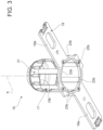
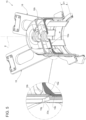
Figures 2 and3 are perspective views respectively from above and below, and with parts removed for clarity, of the support device according to the present invention; -
Figure 4 is a perspective view, with parts removed for clarity, of a pair of support devices stacked on top of one another according to a first stacking configuration; -
Figure 5 is a larger-scale, sectioned perspective view, of the pair of support devices ofFigure 4 ; -
Figure 6 is a perspective view, with parts removed for clarity, of a pair of support devices stacked on top of one another according to a second stacking configuration; -
Figure 7 is a larger-scale, sectioned perspective view, of the pair of support devices ofFigure 5 ; -
Figure 8 is a perspective view, with parts removed for clarity, of a storage unit of the web feeding device ofFigure 1 , including a plurality of support devices according to the invention and stacked one on top of the other according to the first stacking configuration; -
Figure 9 is a perspective view, with parts removed for clarity, of the storage unit ofFigure 8 including a plurality of support devices according to the invention and stacked one on top of the other according to the second stacking configuration. - With reference to
Figure 1 ,number 1 indicates as a whole a labelling machine for labellingarticles 2, such as bottles, flacons, cans or containers of this sort, adapted to contain a pourable product, preferably a pourable food product. - In particular,
labelling machine 1 is configured to applylabels 3 obtained from aweb 4 of labelling material ontoarticles 2. - According to this preferred and non-limiting embodiment,
labels 3 are glued labels, i.e. strips of labelling material that are cut at predetermined lengths fromweb 4 and then sprinkled with glue before their application on therespective articles 2, according to a manner known and not described in detail. -
Web 4 is provided in the form of a continuous strip initially wound aroundreels 5 and is progressively unwound, in use, off eachreel 5, according to a known manner. - As visible in
Figure 1 ,labelling machine 1 comprises: - a conveyor device, preferably a
carousel 6 rotatable around a fixed axis (not shown), preferably vertical, and configured to advance a plurality ofarticles 2 along an arc-shaped labelling path, preferably horizontal; - a labelling module 7 (only schematically shown), arranged peripherally relatively to
carousel 6 and configured to prepare a plurality oflabels 3 and feed them to thecarousel 6 at an application station A, in order to applylabels 3 ontorespective articles 2. -
Labelling module 7 comprises: - a
support unit 8, preferably in the form of two support shafts, for supporting in an unwindable manner eachreel 5; - a plurality of
guide rollers 10, arranged operatively downstream ofsupport unit 8, and configured to control the unwinding ofweb 4 off therespective reel 5, to support theweb 4 progressively unwound fromreel 5 and to guideweb 4 along a feed path; - a cutting unit 11 (known per se and only schematically shown) arranged downstream of
guide rollers 10, along the feed path, and configured to repeatedly cutweb 4 thereby separating a sequence oflabels 3 therefrom; and - a
transfer drum 12, preferably a vacuum drum of the known type, arranged downstream ofcutting unit 11, rotatable about a central axis and configured to transferlabels 3 to application station A for the application thereof ontorespective articles 2. -
Labelling module 7 further comprises a glue roller of the known type (not shown) for sprinkling eachlabel 3 with glue prior to its application onto therespective article 2. -
Labelling module 7 may also comprise asplicing device 13 configured for splicing the terminal portion of afirst web 4 with the initial portion of asecond web 4, according to a manner known and not described in detail. - In use, while such
first web 4 is unwound from the respectivefirst reel 5 in use, a newsecond reel 5, and hence a new web 4 (i.e. the second web 4) must be fed to labellingmodule 7, in order to correctly perform the splicing operation. - To this end, and in order to speed up and automatize the reel change operation,
labelling machine 1 comprises areel feeding system 14 for supplyingreels 5 to labellingmodule 7. -
Feeding system 14 comprises astorage unit 15 configured for storing a plurality ofreels 5. - In detail,
storage unit 15 has a longitudinal axis and is configured for storingreels 5 axially stacked (in a coaxial manner) one on top of the other. - To this end,
storage unit 15 comprises a plurality ofreel support devices 16, which are adapted to be axially stacked on top of one another. - In one embodiment,
storage unit 15 includes at least afirst support device 16a and asecond support device 16b, axially stacked one on top of the other. - In light of the above,
storage unit 15 is defined by at least twosupport devices 16 stacked one on top of the other. - Reference will be made in the following to a
single support device 16 according to the present invention. The structural and functional features described forsuch support device 16 are applicable to eachsupport device 16 that may be present instorage unit 15. - As visible in
Figures 2 and3 ,support device 16 comprises: - a
central hub 17 having a central axis X and adapted for the transport (or transfer) of thesupport device 16 itself, as better described in the following; - a
support base 18 radially extending from thecentral hub 17 and configured for supporting onereel 5 at a time. - In detail,
hub 17 extends axially frombase 18. - Preferably,
base 18 includes twoarms 18a which radially protrude fromhub 17, and in particular from an axial end portion ofhub 17 opposite from an axial free end portion ofhub 17. - In practice,
support device 16 is configured to support therespective reel 5 by means ofbase 18, whereby the flat part ofsuch reel 5, i.e. the circular base ofsuch reel 5, rests onarms 18a. - The
hub 17 is configured to engage a central through hole of the supportedreel 5. - According to a first aspect of the present invention,
support device 16 comprises: - a
first receiving surface 19a and afirst abutment surface 19b; and - a
second receiving surface 20a and asecond abutment surface 20b. - According to a second aspect of the present invention, the
support device 16 is configured for receiving afurther support device 16 selectively onto thefirst receiving surface 19a, by abutment between suchfirst receiving surface 19a and thefirst abutment surface 19b of thefurther support device 16, whereby a first axial distance D1 is defined between the base 18 of thesupport device 16 and thebase 18 of thefurther support device 16, or onto thesecond receiving surface 20a, by abutment between suchsecond receiving surface 20a and thesecond abutment surface 20b of thefurther support device 16, whereby a second axial distance D2 is defined between the base 18 of thesupport device 16 and thebase 18 of thefurther support device 16, the second axial distance D2 being different than the first axial distance D1. - In particular, the
support device 16 according to the invention is configured to be axially stacked with thefurther support device 16 selectively by abutment between itsfirst receiving surface 19a and thefirst abutment surface 19b of thefurther support device 16 for defining a first stacking configuration (Figures 4 and5 ) whereby said first axial distance D1 is defined between therespective bases 18 of thesupport device 16 and thefurther support device 16, or by abutment between itssecond receiving surface 20a and thesecond abutment surface 20b of saidfurther support device 16 for defining a second stacking configuration (Figures 6 and7 ) whereby said second axial distance D2 is defined between therespective bases 18 of thesupport device 16 and thefurther support device 16. - More in particular, the
first receiving surface 19a is configured to receive in abutment thefirst abutment surface 19b of thefurther support device 16 for defining such first stacking configuration, and thesecond receiving surface 20a is configured to receive in abutment thesecond abutment surface 20b of thefurther support device 16 for defining such second stacking configuration. - With reference to
Figures 4 and5 ,storage unit 15 comprises at least afirst support device 16a and asecond support device 16b, which are stacked on top of one another, preferably in a coaxial manner. - For example,
second support device 16b is stacked on top offirst support device 16a. - In detail, when two or
more support devices 16 are axially stacked, theirhubs 17 mutually engage. - In light of the above, the
first receiving surface 19a of thefirst support device 16a is configured to receive (in abutment) thefirst abutment surface 19b of thesecond support device 16b for defining the aforementioned first axial distance D1 between therespective bases 18 of thefirst support device 16a and of thesecond support device 16b. - Similarly, with reference to
Figures 6 and7 , thesecond receiving surface 20a of thefirst support device 16a is configured to receive thesecond abutment surface 20b of thesecond support device 16b for defining the aforementioned second axial distance D2 between therespective bases 18 of thefirst support device 16a andsecond support device 16b. - In one embodiment, the second axial distance D2 is larger than the first axial distance D1.
- According to a further aspect of the present invention, the
support device 16 is configured such that: - the first stacking configuration corresponds to a first mutual angular orientation between the
support device 16 and thefurther support device 16, for example between thefirst support device 16a and thesecond support device 16b (Figure 4 ); and - the second stacking configuration corresponds to a second mutual angular orientation, distinct from the first mutual angular orientation, between the
support device 16 and thefurther support device 16, for example between thefirst support device 16a and thesecond support device 16b (Figure 6 ). - More specifically, the
support device 16 is configured such that the first stacking configuration is activatable by arranging thefirst support device 16a and thesecond support device 16b in a stacked condition whereby they are at the aforementioned first angular mutual orientation, and such that the second stacking configuration is activatable by arranging thefirst support device 16a and thesecond support device 16b in a stacked condition whereby they are at the aforementioned second angular mutual orientation. - Hence, according to the invention, the
storage unit 15 is configured to selectively assume a first stacking configuration, whereby: - the
first support device 16a and thesecond support device 16b are arranged at the first angular mutual orientation, - the
first abutment surface 19b of thesecond support device 16b abuts onto thefirst receiving surface 19a of thefirst support device 16a, and - the first axial distance D1 is defined between the
respective bases 18 of thefirst support device 16a andsecond support device 16b, - the
first support device 16a and thesecond support device 16b are arranged at the second angular mutual orientation, - the
second abutment surface 20b of thesecond support device 16b abuts onto thesecond receiving surface 20a of thefirst support device 16a, and - the second axial distance D2 is defined between the
respective bases 18 of thefirst support device 16a andsecond support device 16b. - In other words, by selectively stacking the same two
support devices 16 on top of one another with either the first mutual angular orientation or the second mutual angular orientation, it is possible to respectively obtain the first stacking configuration or the second stacking configuration, and therefore the first axial distance D1 or the second axial distance D2 between the twobases 18, respectively. The second axial distance D2 is greater than the first axial distance D1. - In this way, thanks to the configuration of the
support device 16 according to the present invention, thestorage unit 15 may accommodate both large-sized reels 5 (Figure 9 ) and small-sized reels 5 while always maximizing the use of the available space therein (Figure 8 ). - It is stated that, for the purpose of the present description, a large-
sized reel 5 is defined as areel 5 having an axial width corresponding at most to the second axial distance D2, and a small-sized reel 5 is defined as areel 5 having an axial width corresponding at most to the first axial distance D1. - Accordingly, in order to store a large-
sized reel 5 in thestorage unit 15, it is sufficient to stack afirst support device 16a in thestorage unit 15 and then stack asecond support device 16b on top offirst support device 16a by selecting/activating the second stacking configuration. The second axial distance D2 is then established between thebases 18 of thefirst support device 16a andsecond support device 16b, which is appropriate for accommodating the large-sized reel 5 (supported by thefirst support device 16a). - Conversely, in order to store a small-
sized reel 5 in thestorage unit 5, it is sufficient to stack afirst support device 16a in thestorage unit 15 and then stack asecond support device 16b on top offirst support device 16a by selecting/activating the first stacking configuration. The first axial distance D1 is then established between thebases 18 of thefirst support device 16a andsecond support device 16b, which is appropriate for accommodating the small-sized reel 5 (supported by thefirst support device 16a). - Therefore, it is not necessary to always provide an axial distance corresponding to the axial width of the large-
sized reel 5, between thestacked support devices 16 in thestorage unit 15. - In light of the above, the
support device 16 according to the present invention allows for maximizing the use of the available space instorage unit 15. - Conveniently, the
second receiving surface 20a is arranged in a position radially more external than thefirst receiving surface 19a (Figure 2 ), and thesecond abutment surface 20b is arranged in a position radially more external than thefirst abutment surface 19b (Figure 3 ) . - This peculiar structural feature enables the implementation of the selection between the first stacking configuration and the second stacking configuration in a simple manner, as better explained below.
- Conveniently, the
first receiving surface 19a, thefirst abutment surface 19b, thesecond receiving surface 20a and thesecond abutment surface 20b are axial, so that said abutment between thefirst receiving surface 19a and thefirst abutment surface 19b is defined in the axial direction and so that that said abutment between thesecond receiving surface 20a and thesecond abutment surface 20b is defined in the axial direction. - This allows for easy centering between two
support devices 16 during abutment, thereby minimizing stacking errors. - Preferably, the
first receiving surface 19a, thefirst abutment surface 19b, thesecond receiving surface 20a and thesecond abutment surface 20b are obtained on thecentral hub 17. - This allows for a more compact configuration and further reduces centering errors during stacking.
- Advantageously, the
second receiving surface 20a and thesecond abutment surface 20b extend about the central axis X in a discontinued manner. - More specifically, the
second receiving surface 20a includes a plurality of portions which are separated from one another byaxial passages 21, are angularly distributed about the central axis X and are angularly interspersed with the passages 21 (which are in turn angularly distributed about axis X). - Similarly, the
second abutment surface 20b includes a plurality of portions separated from one another and angularly distributed about the central axis X. - Advantageously, the
support device 16a is configured such that eachpassage 21 can be crossed by a respective portion of thesecond abutment surface 20b of thefurther support device 16, so as to allow the abutment between thefirst receiving surface 19a and thefirst abutment surface 19b (Figure 4 ). - For example, to obtain the situation depicted in
Figures 4 and5 , thepassages 21 of thefirst support device 16a have been crossed by the respective portions of thesecond abutment surface 20b of thesecond support device 16b. - In practice, the
support device 16 according to the invention is configured such that itspassages 21 are axially aligned with, and crossed by, the respective portions of the second abutment surfaces 20b of thefurther support device 16, while the first stacking configuration is being set with thesupport device 16 and thefurther support device 16 adopting the first mutual orientation. - Furthermore, the
support device 16 is configured such that when thesupport device 16 and the further support device 16 (and for example thefirst support device 16a and thesecond support device 16b) are arranged at the aforementioned second angular mutual orientation, each portion of thesecond receiving surface 20a is axially aligned with a respective portion of thesecond abutment surface 20b of saidfurther support device 16, for defining said second stacking configuration. - It is stated that the first mutual angular orientation can correspond to a plurality of first angular orientations, and the second mutual angular orientation can correspond to a plurality of second angular orientations.
- In this way, the selection between the first stacking configuration and the second stacking configuration can be performed in an easy and simple manner, minimizing the errors in selecting between such two configurations.
- In fact, it is sufficient to axially stack two or
more support devices 16, by axially engaging thehub 17 of afirst support device 16a with thehub 17 of asecond support device 16b, and by choosing the first or second mutual angular orientations between these latter, to selectively activate either the first stacking configuration or second stacking configuration. - In this way, small-
sized reels 5 and/or large-sized reels 5 can be stored instorage unit 15 in a very straightforward way, while also minimizing the occupied space instorage unit 15. - Advantageously, feeding
system 14 further comprises a gripping device 22 (for example a robotic arm) configured to sequentially grip eachsupport device 16 at thecentral hub 17 thereof for transferring therespective reel 5 from thestorage unit 15 to thelabelling module 7. Thegripping device 22 can be part of a robot or part of a cobot. - In this way, it is possible to easily control the orientation in an automatic and repeatable manner, thereby sensibly reducing errors and machine downtime.
- In one embodiment, feeding
system 14 includes a sensor for detecting the size of eachreel 5, and a control unit. - In such embodiment, the control unit is configured to control a movement of the
gripping device 22 based on the information received by the sensor, so as to impart to therelative support device 16 the correct orientation, thereby selecting/activating the first stacking configuration or the second stacking configuration. - From the foregoing, it is clear how the
support device 16 according to the present invention allows to implement a method for stackingreels 5 of labelling material for the labelling ofarticles 2 adapted to contain a pourable product, the method comprising the steps of: - supporting each
reel 5 by means of asupport device 16; - axially stacking a
first support device 16a and asecond support device 16b on top of one another; - abutting the
first abutment surface 19b of thesecond support device 16b onto thefirst receiving surface 19a of thefirst support device 16a, so as to define the first axial distance D1 between therespective bases 18 thereof; or - abutting the
second abutment surface 20b of thesecond support device 16b onto thesecond receiving surface 20a of thefirst support device 16a, so as to define the second axial distance D2 between therespective bases 18 thereof. - The advantages of the
support device 16 according to the present invention will be clear from the foregoing description. - In particular, thanks to the configuration of the
support device 16 according to the present invention, the space allocated for thestacked reels 5 in thestorage unit 15 can be minimized, thereby maximizing the use of the available space therein. - Furthermore, this allows for increasing the autonomy of the
labelling module 7 and, ultimately, of thelabelling machine 1, because the increase in available space instorage unit 15 allows for a larger number ofreels 5 to be stored therein. - Ultimately, the overall productivity of the
labelling machine 1 is increased. - Clearly, changes may be made to support
device 16 as described herein without, however, departing from the scope of protection as defined in the accompanying claims.
Claims (15)
- Support device (16) for supporting a reel (5) of labelling material for labelling articles (2) adapted to contain a pourable product, the support device (16) comprising:- a central hub (17) having a central axis (X) and adapted for the transport of the support device (16);- a support base (18) radially extending from the central hub (17) and configured for supporting one reel (5) at a time;- a first receiving surface (19a) and a first abutment surface (19b);- a second receiving surface (20a) and a second abutment surface (20b);wherein the support device (16) is configured for receiving a further support device (16) selectively onto the first receiving surface (19a), by abutment between such first receiving surface (19a) and the first abutment surface (19b) of said further support device (16), whereby a first axial distance (D1) is defined between the base (18) of the support device (16) and the base (18) of said further support device (16), or onto the second receiving surface (20a), by abutment between such second receiving surface (20a) and the second abutment surface (20b) of said further support device (16), whereby a second axial distance (D2) is defined between the base (18) of the support device (16) and the base (18) of said further support device (16), the second axial distance (D2) being different and greater than the first axial distance (D1).
- Support device as claimed in claim 1, wherein the support device (16) is configured to be axially stacked with said further support device (16) selectively by abutment between its first receiving surface (19a) and the first abutment surface (19b) of said further support device (16) for defining a first stacking configuration whereby said first axial distance (D1) is defined between the respective bases (18) of the support device (16) and the further support device (16), or by abutment between its second receiving surface (20a) and the second abutment surface (20b) of said further support device (16) for defining a second stacking configuration whereby said second axial distance (D2) is defined between the respective bases (18) of the support device (16) and the further support device (16).
- Support device as claimed in claim 2, wherein:- the first receiving surface (19a) is configured to receive in abutment the first abutment surface (19b) of said further support device (16) for defining said first stacking configuration, and- the second receiving surface (20a) is configured to receive in abutment the second abutment surface (20b) of said further support device (16) for defining said second stacking configuration.
- Support device as claimed in claim 2 or 3, wherein the support device (16) is configured such that:- the first stacking configuration corresponds to a first angular mutual orientation between the support device (16) and the further support device (16), and- the second stacking configuration corresponds to a second angular mutual orientation, distinct from the first angular mutual orientation, between the support device (16) and the further support device (16).
- Support device as claimed in claim 4, wherein the support device (16) is configured such that the first stacking configuration is activatable by arranging the support device (16) and said further support device (16) in a stacked condition whereby the support device (16) and the further support device (16) are at said first angular mutual orientation, and such that the second stacking configuration is activatable by arranging the support device (16) and said further support device (16) in a stacked condition whereby the support device (16) and the further support device (16) are at said second angular mutual orientation.
- Support device as claimed in any one of the foregoing claims, wherein the second receiving surface (20a) is arranged in a position radially more external than the first receiving surface (19a), and the second abutment surface (20b) is arranged in a position radially more external than the first abutment surface (20a).
- Support device as claimed in claim 6, wherein the second receiving surface (20a) and the second abutment surface (20b) extend about the central axis (X) in a discontinued manner.
- Support device as claimed in claim 7, wherein the second receiving surface (20a) includes a plurality of portions which are separated from one another by axial passages (21), are angularly distributed about the central axis (X) and are angularly interspersed with the passages (21), and the second abutment surface (20b) includes a plurality of portions separated from one another and angularly distributed about the central axis (X),
the support device (16) being configured such that each passage (21) can be crossed by a respective portion of the second abutment surface (20b) of said further support device (16), so as to allow said abutment between the first receiving surface (19a) and the first abutment surface (19b). - Support device as claimed in claims 4 and 8, wherein the support device (16) is configured such that the passages (21) are axially aligned with, and crossed by, the respective portions of the second abutment surfaces (20b) of the further support device (16), while the first stacking configuration is being set with the support device (16) and the further support device (16) adopting the first mutual orientation.
- Support device as claimed in claim 9, wherein the support device (16) is configured such that each portion of the second receiving surface (20a) is axially aligned with a respective portion of the second abutment surface (20b) of said further support device (16) when the support device (16) and the further support device (16) are at said second angular mutual orientation, for defining said second stacking configuration.
- Reel feeding system (14) for supplying reels (5) of labelling material to a labelling module (7) of a labelling machine (1) for labelling articles (2) adapted to contain a pourable product, the reel feeding system (14) including a storage unit (15) configured for storing a plurality of said reels (5) and comprising at least a first support device (16a) and a second support device (16b), each of said first device (16a) and second device (16b) being as claimed in any one of the foregoing claims and said first device (16a) and second device (16b) being axially stacked one on top of the other;
wherein:- the first receiving surface (19a) of the first support device (16a) is configured to receive the first abutment surface (19b) of the second support device (16b) for defining said first axial distance (D1) between the respective bases (18) of the first support device (16a) and second support device (16b); and- the second receiving surface (20a) of the first support device (16a) is configured to receive the second abutment surface (20b) of the second support device (16b) for defining said second axial distance (D2) between the respective bases (18) of the first support device (16a) and second support device (16b). - Reel feeding system as claimed in claim 11, wherein the storage unit (15) is configured to selectively assume a first stacking configuration, whereby:- the first support device (16a) and the second support device (16b) are arranged at a first angular mutual orientation,- the first abutment surface (19b) of the second support device (16b) abuts onto the first receiving surface (19a) of the first support device (16a), and- said first axial distance (D1) is defined between the respective bases (18) of the first support device (16a) and second support device (16b),and a second stacking configuration, whereby:- the first support device (16a) and the second support device (16b) are arranged at a second angular mutual orientation,- the second abutment surface (20b) of the second support device (16b) abuts onto the second receiving surface (20a) of the first support device (16a), and- said second axial distance (D2) is defined between the respective bases (18) of the first support device (16a) and second support device (16b).
- Reel feeding system as claimed in claim 11 or 12, and further comprising a gripping device (14) configured to sequentially grip each support device (16a, 16b) at the central hub (17) thereof for transferring the respective reel (5) from the storage unit (15) to said labelling module (7), the gripping device (14) being preferably part of a robot or cobot.
- Labelling machine (1) for labelling articles (2) adapted to contain a pourable product, the labelling machine (1) comprising:- a conveyor device (6) for advancing a sequence of articles (2) to be labelled along a labelling path;- a labelling module (7) for labelling the articles (2) advanced along the labelling path; and- a reel feeding system (14) as claimed in any one of claims 11 to 13.
- Method for stacking reels (5) of labelling material for the labelling of articles (2) adapted to contain a pourable product, the method comprising the steps of:- supporting each reel (5) by means of a support device (16) as claimed in any one of claims 1 to 10;- axially stacking a first support device (16a) and a second support device (16b) on top of one another;wherein the step of axially stacking is carried out by selectively:- abutting the first abutment surface (19b) of the first support device (16b) onto the first receiving surface (19a) of the second support device (16a), so as to define the first axial distance (D1) between the respective bases (18) of the first support device (16a) and the second support device (16b); or- abutting the second abutment surface (20b) of the first support device (16b) onto the second receiving surface (20a) of the second support device (16a), so as to define the second axial distance (D2) between the respective bases (18) of the first support device (16a) and the second support device (16b).
Priority Applications (2)
| Application Number | Priority Date | Filing Date | Title |
|---|---|---|---|
| EP23209293.2A EP4553021A1 (en) | 2023-11-13 | 2023-11-13 | Reel support device for double stacking configuration |
| PCT/EP2024/080059 WO2025103728A1 (en) | 2023-11-13 | 2024-10-24 | Reel support device fot double stacking configuration |
Applications Claiming Priority (1)
| Application Number | Priority Date | Filing Date | Title |
|---|---|---|---|
| EP23209293.2A EP4553021A1 (en) | 2023-11-13 | 2023-11-13 | Reel support device for double stacking configuration |
Publications (1)
| Publication Number | Publication Date |
|---|---|
| EP4553021A1 true EP4553021A1 (en) | 2025-05-14 |
Family
ID=88793257
Family Applications (1)
| Application Number | Title | Priority Date | Filing Date |
|---|---|---|---|
| EP23209293.2A Pending EP4553021A1 (en) | 2023-11-13 | 2023-11-13 | Reel support device for double stacking configuration |
Country Status (2)
| Country | Link |
|---|---|
| EP (1) | EP4553021A1 (en) |
| WO (1) | WO2025103728A1 (en) |
Citations (1)
| Publication number | Priority date | Publication date | Assignee | Title |
|---|---|---|---|---|
| EP3760550A1 (en) * | 2019-07-04 | 2021-01-06 | Sidel Participations | Unit for transferring reels of labelling material |
-
2023
- 2023-11-13 EP EP23209293.2A patent/EP4553021A1/en active Pending
-
2024
- 2024-10-24 WO PCT/EP2024/080059 patent/WO2025103728A1/en active Pending
Patent Citations (1)
| Publication number | Priority date | Publication date | Assignee | Title |
|---|---|---|---|---|
| EP3760550A1 (en) * | 2019-07-04 | 2021-01-06 | Sidel Participations | Unit for transferring reels of labelling material |
Also Published As
| Publication number | Publication date |
|---|---|
| WO2025103728A1 (en) | 2025-05-22 |
Similar Documents
| Publication | Publication Date | Title |
|---|---|---|
| EP3760550A1 (en) | Unit for transferring reels of labelling material | |
| US11186401B2 (en) | Labelling machine configured to apply labels onto articles for containing a pourable product | |
| CN107548376B (en) | Method and device for feeding, supplying and changing rolls with flat and/or film material wound thereon | |
| US3765991A (en) | Labeling apparatus | |
| US9309016B2 (en) | Automatic container orientation systems and methods | |
| US20250353636A1 (en) | Web feeding system for a labelling module for preparing the splicing operation | |
| EP4310038A1 (en) | Labelling machine for labelling containers adapted to contain a pourable product and method for splicing two webs of labelling material | |
| CN117068502A (en) | Wheeled conveyor for conveying containers, machine and method for applying flexible carrier to a plurality of containers | |
| CN212922305U (en) | Labeling unit and automatic adjusting system for labeling unit | |
| EP0450821A2 (en) | Labeling machine and method | |
| EP4490088B1 (en) | Plant and method for labeling reels of web material | |
| CN112930305B (en) | Labeling machine and method for handling labeling material in roll form in an automatic labeling process | |
| WO2025103728A1 (en) | Reel support device fot double stacking configuration | |
| US4588344A (en) | Roll transfer robot | |
| CN110997503B (en) | Container labelling machine | |
| US6616780B1 (en) | Method and device for supplying labels to labeling device | |
| US4575016A (en) | Continuous ribbon feed method and system | |
| WO2026032495A1 (en) | Web feeding system for a labelling module for preparing the splicing operation with spraying function | |
| EP4703307A1 (en) | Web feeding system with covering element on web leading portion | |
| CN109927988B (en) | Automatic packaging machine for preservative film rolls | |
| WO2020114766A1 (en) | Labelling machine, method for handling a web-like labelling material in an automated labelling process and label | |
| EP4520674A1 (en) | Label transfer drum with single-piece pad devices for labelling containers by means of partial labels | |
| EP3988462A1 (en) | Labelling machine and method for applying labels onto articles adapted to contain a pourable product | |
| WO2025036797A1 (en) | Labelling machine configured for labelling containers by means of partial labels by sliding application | |
| EP3115308A1 (en) | A label application apparatus and method |
Legal Events
| Date | Code | Title | Description |
|---|---|---|---|
| PUAI | Public reference made under article 153(3) epc to a published international application that has entered the european phase |
Free format text: ORIGINAL CODE: 0009012 |
|
| STAA | Information on the status of an ep patent application or granted ep patent |
Free format text: STATUS: THE APPLICATION HAS BEEN PUBLISHED |
|
| AK | Designated contracting states |
Kind code of ref document: A1 Designated state(s): AL AT BE BG CH CY CZ DE DK EE ES FI FR GB GR HR HU IE IS IT LI LT LU LV MC ME MK MT NL NO PL PT RO RS SE SI SK SM TR |
|
| STAA | Information on the status of an ep patent application or granted ep patent |
Free format text: STATUS: REQUEST FOR EXAMINATION WAS MADE |
|
| 17P | Request for examination filed |
Effective date: 20251105 |
|
| STAA | Information on the status of an ep patent application or granted ep patent |
Free format text: STATUS: EXAMINATION IS IN PROGRESS |
|
| 17Q | First examination report despatched |
Effective date: 20260219 |