EP4552943A1 - Energy absorbing and dissipating device for vehicle coupling - Google Patents
Energy absorbing and dissipating device for vehicle coupling Download PDFInfo
- Publication number
- EP4552943A1 EP4552943A1 EP24211035.1A EP24211035A EP4552943A1 EP 4552943 A1 EP4552943 A1 EP 4552943A1 EP 24211035 A EP24211035 A EP 24211035A EP 4552943 A1 EP4552943 A1 EP 4552943A1
- Authority
- EP
- European Patent Office
- Prior art keywords
- housing
- locking element
- fork
- mounting ring
- sleeve
- Prior art date
- Legal status (The legal status is an assumption and is not a legal conclusion. Google has not performed a legal analysis and makes no representation as to the accuracy of the status listed.)
- Granted
Links
Images



Classifications
-
- B—PERFORMING OPERATIONS; TRANSPORTING
- B61—RAILWAYS
- B61G—COUPLINGS; DRAUGHT AND BUFFING APPLIANCES
- B61G11/00—Buffers
- B61G11/16—Buffers absorbing shocks by permanent deformation of buffer element
-
- B—PERFORMING OPERATIONS; TRANSPORTING
- B61—RAILWAYS
- B61G—COUPLINGS; DRAUGHT AND BUFFING APPLIANCES
- B61G9/00—Draw-gear
- B61G9/04—Draw-gear combined with buffing appliances
- B61G9/06—Draw-gear combined with buffing appliances with rubber springs
Definitions
- the present invention relates to an energy absorbing and dissipating device for vehicle coupling having a fork, wherein the fork has a pin mounted therein for mounting the lug assembly connecting the vehicle coupling head, and on the rear side of the fork a pin is mounted with a set of shock-absorbing inserts, the set of inserts on the side of the fork being secured by a stop plate, constituting a limiter for movement in the coupling pulling direction, and on the opposite side by a back plate and a locking element, and the entire structure is closed by a locking element mounted inside the housing, constituting a limiter for movement in the coupling pushing direction, the device additionally having a housing in which the other components can move slidingly.
- Coupling shock absorbers are commonly used to connect vehicles, such as locomotives and railway cars. They are used to absorb vibrations and stresses in the coupling caused by the pull of one vehicle by another, e.g. when a vehicle starts pulling a coupled railway car, and the push of one vehicle by another, e.g. when a vehicle stops and the pulled car gets closer, or during the coupling procedure if it is carried out with automatic couplings. Some such devices are also equipped with an additional mechanism to dissipate energy in the event of a collision, usually in the form of a deformable component.
- a device of this type is presented in the EP3442847B1 document, equipped with a housing in which the shock absorber components are slidably mounted, an element of the shock absorber is a pin with a set of shock-absorbing discs, while an additional component for dissipating energy at collision is a deformable (plastic deformation) sleeve.
- the EP2640620B1 document discloses a device equipped with a housing in which the shock absorber components are slidably mounted, while the component for energy dissipation is a rod, the outer surface of which is sheared by shearing blades mounted on its circumference.
- the present invention solves the above problem.
- the present invention relates to an energy absorbing and dissipating device for vehicle coupling having a fork, wherein the fork has a pin mounted therein for mounting the lug assembly connecting the vehicle coupling head, and on the rear side of the fork a pin is mounted with a set of shock-absorbing inserts.
- the set of shock-absorbing inserts on the side of the fork is secured by a stop plate, constituting a limiter for movement in the coupling pulling direction, and on the opposite side by a back plate and a locking element, and the entire structure is closed by a locking element mounted inside the housing, constituting a limiter for movement in the coupling pushing direction.
- the device also has a housing in which the other components can move slidingly.
- the device is characterized in that
- the set of shock-absorbing inserts consists of elastomeric inserts separated by spacers.
- the housing is shaped like a sleeve.
- the locking element is also a sleeve located inside the housing and threaded to it.
- the housing in the form of a sleeve has at least one cutout at the rear end running from the edge of the sleeve substantially to the mounting ring.
- the locking element is shaped like a sleeve with flattened walls, the flattened walls correspond to the cutouts in the housing, and the locking element is connected to the housing with pins and screws.
- the locking element is a nut.
- the mounting ring is connected to the housing by means of a weld.
- the housing on the outer surface of the front end has a protrusion that serves as a housing stroke limiter. More favorably, the protrusion runs around the entire circumference of the housing.
- the breakaway part is separated from the middle part by a weakening area.
- the breakaway part is connected to the middle part by breakaway screws.
- the housing has two cutouts located at the top and bottom of the housing.
- fig. 1 and fig. 2 show the embodiment of the invention in longitudinal section from the side and from above
- fig. 3 shows a view of the device according to the invention from the side of the pin, and a cross-section along the D-D line of a mounting ring section
- fig. 4-5 shows perspective views of the device according to the embodiment from fig. 1-2 from the side of the pin and from the side of the end installed in the vehicle, respectively
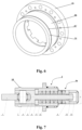
- fig. 6 shows a perspective view of the mounting ring
- fig. 7-8 show another embodiment of the invention in longitudinal section from the side and from above
- fig. 9 shows a perspective view of this embodiment from the side of the end installed in the vehicle.
- fig. 1 and fig. 2 show the embodiment of the invention in longitudinal section from the side and from above
- fig. 3 shows a view of the device according to the invention from the side of the pin, and a cross-section along the D-D line of a mounting ring section
- fig. 4-5 shows perspective views of the device
- the energy absorbing and dissipating device for vehicle coupling has a fork (3), wherein the fork has a pin (7) for mounting the ear assembly (1) connecting the vehicle coupling head, and on the rear side of the fork (3) a pin is mounted with a set of cushioning inserts (11).
- the set of inserts (11) on the side of the fork (3) is secured by a stop plate (5), constituting a limiter for movement in the coupling pulling direction, and on the opposite side by a back plate (6) and a locking element (13), and the entire structure is closed by a locking element (10) mounted inside the housing (4), constituting a limiter for movement in the coupling pushing direction.
- the device also has a housing (4) in which the other components can move slidingly.
- the housing (4) is shaped like a sleeve.
- the mounting ring (2) has a flange part (2a) with screw holes (2a') for mounting to the vehicle wall and cutting knives (14) for cutting the housing surface (4), middle part (2b) for guiding the housing (4) and the breakaway part (2c).
- the knives can be attached to the flange part (2a) with screws (15) or any other way state-of-the-art method.
- the mounting ring (2) is attached to the housing (2) using the breakaway part (2c).
- the set of shock-absorbing inserts (11) consists of elastomeric inserts (11) separated by spacers (12), but shock-absorbing elements of other types known in the field can also be used.
- the housing (4) is a sleeve and the locking element (10) is a sleeve located inside the housing (4) and threaded to it.
- the locking element (13) is a nut, but it can be any other locking element known to the state of the art.
- the mounting ring (2) is connected to the housing (4) by means of a weld (8).
- the embodiment shown in fig. 7-9 differs from the previous one in that the housing (4) in the form of a sleeve has at least one cutout (4a) at the rear end running from the edge of the sleeve substantially to the mounting ring (2), and the locking element (10) is shaped like a sleeve with flattened walls.
- the flattened walls correspond to the cutouts (4a) in the housing (4), and the locking element (10) is connected to the housing (4) with pins (19) and screws (17).
- the housing (4) has two (4a) cutouts located at the top and bottom of housing (4), but a different number of cutouts (4a) can be used, such as more (reducing the weight of the device) or just one (a compromise between weight and durability).
- the housing (4) on the outer surface of the front end has a protrusion (18) that serves as a housing (4) stroke limiter and preferably this protrusion (18) runs around the entire housing (4) circumference (but it is not necessary). The protrusion (18) is used to limit the stroke of housing (4) in the event of vehicle collision.
- the breakaway part (2c) of the mounting ring (2) is separated from the middle part (2b) by a weakening area (2c') - this element is best seen in fig. 6 (without the attached knives (14)).
- the breakaway part (2c) is connected to the middle part (2b) by breakaway screws.
- the device is mainly used in center couplings (though not limited to them) and is used to absorb energy in the reversible range (shock absorption of ordinary movements between coupled vehicles) and in the collision range (absorbing energy from an uncontrolled collision).
- the device is mounted to the vehicle with a mounting ring (2), in such a way that the part on the vehicle side is placed in a compartment within the vehicle and mounted to the vehicle wall with bolts passing through the flange part (2a) and the vehicle wall.
- the center coupling head (not shown) is mounted to the lug assembly (1) in a manner that takes away all degrees of freedom. It can be, for example, a threaded connection.
- a set of shock-absorbing inserts (11) (e.g. elastomeric inserts [11] and spacers [12], as shown in the embodiment) is used to absorb energy in the reversible range.
- force is transmitted from the lug assembly (1) through the pin (7), fork (3), stop plate (5), insert set (11), back plate (6), locking element (10), housing (4) and mounting ring (2) to the vehicle.
- the set of inserts (11) becomes compressed and absorbs energy.
- force is transmitted from the lug assembly (1) through the pin (7), fork (3), locking element (13), back plate (6), insert set (11), stop plate (5), housing (4) and mounting ring (2) to the vehicle.
- the set of inserts (11) becomes compressed and absorbs energy.
- a cutting technology is used to absorb energy in the collision range. If the force exceeds the preset value during the push described above, the breakaway part (2c) will be separated from the middle part (2b) of the mounting ring (2) and the force will no longer be transmitted from the housing (4) to the mounting ring (2), the housing (4) with the separated breakaway part (2c) will slide inside the vehicle cavity and the force will be transmitted from the housing (4) to the knives (14) in the flange part (2a). During this process, the knives (14) punch grooves in the outer surface of the housing (4), which is associated with energy absorption.
Landscapes
- Engineering & Computer Science (AREA)
- Mechanical Engineering (AREA)
- Vibration Dampers (AREA)
Abstract
Description
- The present invention relates to an energy absorbing and dissipating device for vehicle coupling having a fork, wherein the fork has a pin mounted therein for mounting the lug assembly connecting the vehicle coupling head, and on the rear side of the fork a pin is mounted with a set of shock-absorbing inserts, the set of inserts on the side of the fork being secured by a stop plate, constituting a limiter for movement in the coupling pulling direction, and on the opposite side by a back plate and a locking element, and the entire structure is closed by a locking element mounted inside the housing, constituting a limiter for movement in the coupling pushing direction, the device additionally having a housing in which the other components can move slidingly.
- Coupling shock absorbers are commonly used to connect vehicles, such as locomotives and railway cars. They are used to absorb vibrations and stresses in the coupling caused by the pull of one vehicle by another, e.g. when a vehicle starts pulling a coupled railway car, and the push of one vehicle by another, e.g. when a vehicle stops and the pulled car gets closer, or during the coupling procedure if it is carried out with automatic couplings. Some such devices are also equipped with an additional mechanism to dissipate energy in the event of a collision, usually in the form of a deformable component.
- A device of this type is presented in the
EP3442847B1 document, equipped with a housing in which the shock absorber components are slidably mounted, an element of the shock absorber is a pin with a set of shock-absorbing discs, while an additional component for dissipating energy at collision is a deformable (plastic deformation) sleeve. - The
EP2640620B1 document discloses a device equipped with a housing in which the shock absorber components are slidably mounted, while the component for energy dissipation is a rod, the outer surface of which is sheared by shearing blades mounted on its circumference. - Known solutions are mounted in a special recess in the wall of a vehicle (e.g., locomotive, railway car) in such a way that substantially all of it, except for a protruding hitch for coupling another vehicle, fits within the recess. Such solutions take up quite a lot of space in the car and, in addition, access to their components, such as for servicing purposes, is difficult.
- The present invention solves the above problem.
- The present invention relates to an energy absorbing and dissipating device for vehicle coupling having a fork, wherein the fork has a pin mounted therein for mounting the lug assembly connecting the vehicle coupling head, and on the rear side of the fork a pin is mounted with a set of shock-absorbing inserts. The set of shock-absorbing inserts on the side of the fork is secured by a stop plate, constituting a limiter for movement in the coupling pulling direction, and on the opposite side by a back plate and a locking element, and the entire structure is closed by a locking element mounted inside the housing, constituting a limiter for movement in the coupling pushing direction. The device also has a housing in which the other components can move slidingly. The device is characterized in that
- the housing is shaped like a sleeve,
- there is a mounting ring on the outside of the housing; the mounting ring has
a flange part with screw holes for mounting to the vehicle wall and with - cutting knives for cutting the housing surface,
- middle part for guiding the housing,
- breakaway part;
- the mounting ring is mounted to the housing using the breakaway part.
- Preferably, the set of shock-absorbing inserts consists of elastomeric inserts separated by spacers.
- Preferably, the housing is shaped like a sleeve.
- More preferably, the locking element is also a sleeve located inside the housing and threaded to it.
- Also more preferably, the housing in the form of a sleeve has at least one cutout at the rear end running from the edge of the sleeve substantially to the mounting ring. Even more preferably, the locking element is shaped like a sleeve with flattened walls, the flattened walls correspond to the cutouts in the housing, and the locking element is connected to the housing with pins and screws.
- Preferably, the locking element is a nut.
- Preferably, the mounting ring is connected to the housing by means of a weld.
- Preferably, the housing on the outer surface of the front end has a protrusion that serves as a housing stroke limiter. More favorably, the protrusion runs around the entire circumference of the housing.
- Preferably, the breakaway part is separated from the middle part by a weakening area.
- Preferably, the breakaway part is connected to the middle part by breakaway screws.
- More preferably, the housing has two cutouts located at the top and bottom of the housing.
- The present invention is shown in the embodiment images, where
fig. 1 and fig. 2 show the embodiment of the invention in longitudinal section from the side and from above,fig. 3 shows a view of the device according to the invention from the side of the pin, and a cross-section along the D-D line of a mounting ring section,fig. 4-5 shows perspective views of the device according to the embodiment fromfig. 1-2 from the side of the pin and from the side of the end installed in the vehicle, respectively,fig. 6 shows a perspective view of the mounting ring,fig. 7-8 show another embodiment of the invention in longitudinal section from the side and from above, andfig. 9 shows a perspective view of this embodiment from the side of the end installed in the vehicle. For clarity, not all components are labeled on all figures. - As can be observed in the figures, in the embodiment the energy absorbing and dissipating device for vehicle coupling has a fork (3), wherein the fork has a pin (7) for mounting the ear assembly (1) connecting the vehicle coupling head, and on the rear side of the fork (3) a pin is mounted with a set of cushioning inserts (11). The set of inserts (11) on the side of the fork (3) is secured by a stop plate (5), constituting a limiter for movement in the coupling pulling direction, and on the opposite side by a back plate (6) and a locking element (13), and the entire structure is closed by a locking element (10) mounted inside the housing (4), constituting a limiter for movement in the coupling pushing direction. The device also has a housing (4) in which the other components can move slidingly. The housing (4) is shaped like a sleeve. There is a mounting ring (2) on the outside of the housing (4). The mounting ring (2) has a flange part (2a) with screw holes (2a') for mounting to the vehicle wall and cutting knives (14) for cutting the housing surface (4), middle part (2b) for guiding the housing (4) and the breakaway part (2c). The knives can be attached to the flange part (2a) with screws (15) or any other way state-of-the-art method. The mounting ring (2) is attached to the housing (2) using the breakaway part (2c). In a preferrable embodiment, the set of shock-absorbing inserts (11) consists of elastomeric inserts (11) separated by spacers (12), but shock-absorbing elements of other types known in the field can also be used. In the embodiment shown in
fig. 1-2 ,4-5 the housing (4) is a sleeve and the locking element (10) is a sleeve located inside the housing (4) and threaded to it. In the embodiment, the locking element (13) is a nut, but it can be any other locking element known to the state of the art. In a preferrable embodiment, the mounting ring (2) is connected to the housing (4) by means of a weld (8). - The embodiment shown in
fig. 7-9 differs from the previous one in that the housing (4) in the form of a sleeve has at least one cutout (4a) at the rear end running from the edge of the sleeve substantially to the mounting ring (2), and the locking element (10) is shaped like a sleeve with flattened walls. The flattened walls correspond to the cutouts (4a) in the housing (4), and the locking element (10) is connected to the housing (4) with pins (19) and screws (17). In the example shown, the housing (4) has two (4a) cutouts located at the top and bottom of housing (4), but a different number of cutouts (4a) can be used, such as more (reducing the weight of the device) or just one (a compromise between weight and durability). In this embodiment, the housing (4) on the outer surface of the front end has a protrusion (18) that serves as a housing (4) stroke limiter and preferably this protrusion (18) runs around the entire housing (4) circumference (but it is not necessary). The protrusion (18) is used to limit the stroke of housing (4) in the event of vehicle collision. - In the embodiments shown in the figures, the breakaway part (2c) of the mounting ring (2) is separated from the middle part (2b) by a weakening area (2c') - this element is best seen in
fig. 6 (without the attached knives (14)). In another embodiment (not shown), the breakaway part (2c) is connected to the middle part (2b) by breakaway screws. - The device is mainly used in center couplings (though not limited to them) and is used to absorb energy in the reversible range (shock absorption of ordinary movements between coupled vehicles) and in the collision range (absorbing energy from an uncontrolled collision). The device is mounted to the vehicle with a mounting ring (2), in such a way that the part on the vehicle side is placed in a compartment within the vehicle and mounted to the vehicle wall with bolts passing through the flange part (2a) and the vehicle wall. The center coupling head (not shown) is mounted to the lug assembly (1) in a manner that takes away all degrees of freedom. It can be, for example, a threaded connection.
- A set of shock-absorbing inserts (11) (e.g. elastomeric inserts [11] and spacers [12], as shown in the embodiment) is used to absorb energy in the reversible range. During pushing, force is transmitted from the lug assembly (1) through the pin (7), fork (3), stop plate (5), insert set (11), back plate (6), locking element (10), housing (4) and mounting ring (2) to the vehicle. During pushing, the set of inserts (11) becomes compressed and absorbs energy. During pulling, force is transmitted from the lug assembly (1) through the pin (7), fork (3), locking element (13), back plate (6), insert set (11), stop plate (5), housing (4) and mounting ring (2) to the vehicle. During pulling, the set of inserts (11) becomes compressed and absorbs energy.
- A cutting technology is used to absorb energy in the collision range. If the force exceeds the preset value during the push described above, the breakaway part (2c) will be separated from the middle part (2b) of the mounting ring (2) and the force will no longer be transmitted from the housing (4) to the mounting ring (2), the housing (4) with the separated breakaway part (2c) will slide inside the vehicle cavity and the force will be transmitted from the housing (4) to the knives (14) in the flange part (2a). During this process, the knives (14) punch grooves in the outer surface of the housing (4), which is associated with energy absorption.
- Of course, the invention is not limited to the embodiments described above, and the features indicated in the claims may be combined with each other in any combinations appropriate for a given application of the solution.
Claims (13)
- An energy absorbing and dissipating device for vehicle coupling having a fork (3), wherein the fork (3) has a pin (7) mounted therein for mounting the lug assembly (1) connecting the vehicle coupling head, and on the rear side of the fork (3) a pin is mounted with a set of cushioning inserts (11), the set of inserts (11) on the side of the fork (3) being secured by a stop plate (5), constituting a limiter for movement in the coupling pulling direction, and on the opposite side by a back plate (6) and a locking element (13), and the entire structure is closed by a locking element (10), constituting a limiter for movement in the coupling pushing direction, the device additionally having a housing (4) in which the other components can move slidingly, and in which the locking element (10) is mounted, characterized in thatthe housing (4) is shaped like a sleeve,there is a mounting ring (4) on the outside of the housing (2); the mounting ring (2) hasa flange part (2a) with screw holes (2a') for mounting to the vehicle wall and with cutting knives (14) for cutting the housing surface (4),a middle part (2b) for running the housing (4),a breakaway part (2c); andthe mounting ring (2) is mounted to the housing (4) using the breakaway part (2c).
- The device according to claim 1, characterized in that the set of shock-absorbing inserts (11) are elastomeric inserts (11) separated by spacers (12).
- The device according to claim 1, characterized in that the housing (4) is a sleeve.
- The device according to claim 3, characterized in that the locking element (10) is a sleeve located inside the housing (4) and threaded to it.
- The device according to claim 3, characterized in that the housing (4) in the form of a sleeve has at least one cutout (4a) at the rear end running from the edge of the sleeve (4) substantially to the mounting ring (2).
- The device according to claim 5, characterized in that the locking element (10) is shaped like a sleeve with flattened walls, the flattened walls correspond to the cutouts (4a) in the housing (4), and the locking element (10) is connected to the housing (4) with pins (19) and screws (17).
- The device according to claim 1, characterized in that the locking element (13) is a nut.
- The device according to claim 1, characterized in that the mounting ring (2) is connected to the housing (4) by means of a weld (8).
- The device according to claim 1, characterized in that the housing (4) on the outer surface of the front end has a protrusion (18) that serves as a housing (4) stroke limiter.
- The device according to claim 9, characterized in that the protrusion (18) runs around the entire circumference of the housing (4).
- The device according to claim 1, characterized in that the breakaway part (2c) is separated from the middle part (2b) by a weakened area (2c').
- The device according to claim 1, characterized in that the breakaway part (2c) is connected to the middle part (2b) by breakaway screws.
- The device according to claim 5, characterized in that the housing (4) has two cutouts (4a) located at the top and bottom of the housing (4).
Applications Claiming Priority (1)
| Application Number | Priority Date | Filing Date | Title |
|---|---|---|---|
| PL446687A PL248526B1 (en) | 2023-11-09 | 2023-11-09 | Energy absorption and dissipation device for vehicle coupling |
Publications (2)
| Publication Number | Publication Date |
|---|---|
| EP4552943A1 true EP4552943A1 (en) | 2025-05-14 |
| EP4552943B1 EP4552943B1 (en) | 2026-03-11 |
Family
ID=95398930
Family Applications (1)
| Application Number | Title | Priority Date | Filing Date |
|---|---|---|---|
| EP24211035.1A Active EP4552943B1 (en) | 2023-11-09 | 2024-11-06 | Energy absorbing and dissipating device for vehicle coupling |
Country Status (2)
| Country | Link |
|---|---|
| EP (1) | EP4552943B1 (en) |
| PL (1) | PL248526B1 (en) |
Citations (5)
| Publication number | Priority date | Publication date | Assignee | Title |
|---|---|---|---|---|
| EP2072370B1 (en) * | 2007-12-17 | 2010-06-23 | Voith Patent GmbH | Energy absorbing device for a vehicle body of a multi-unit vehicle |
| EP2640620B1 (en) | 2010-11-16 | 2017-07-05 | AXTONE Spólka Akcyjna | Coupler assembly for coupling railway wagons |
| US20180043911A1 (en) * | 2015-03-05 | 2018-02-15 | Axtone Spolka Akcyjna | Impact energy absorber |
| US20200189627A1 (en) * | 2017-08-29 | 2020-06-18 | Axtone S.A. | Absorbing apparatus |
| EP3442847B1 (en) | 2016-04-11 | 2023-08-30 | Voith Patent GmbH | Pull and push means |
Family Cites Families (5)
| Publication number | Priority date | Publication date | Assignee | Title |
|---|---|---|---|---|
| WO2012016723A1 (en) * | 2010-08-06 | 2012-02-09 | Voith Patent Gmbh | Energy absorption device, in particular for a shock absorber of a track-guided vehicle |
| PL222340B1 (en) * | 2012-10-30 | 2016-07-29 | Axtone Spółka Z Ograniczoną Odpowiedzialnością | Multilevel rail bumper |
| PL226548B1 (en) * | 2014-12-02 | 2017-08-31 | Axtone Spółka Z Ograniczoną Odpowiedzialnością | Device absorbing the energy of railway wagons strikes |
| PL235386B1 (en) * | 2017-05-22 | 2020-07-13 | Axtone Spolka Akcyjna | Device that dissipates railway wagons strikes energy |
| KR20220049684A (en) * | 2020-10-14 | 2022-04-22 | 한국철도기술연구원 | energy absorbing device for railway vehicle |
-
2023
- 2023-11-09 PL PL446687A patent/PL248526B1/en unknown
-
2024
- 2024-11-06 EP EP24211035.1A patent/EP4552943B1/en active Active
Patent Citations (5)
| Publication number | Priority date | Publication date | Assignee | Title |
|---|---|---|---|---|
| EP2072370B1 (en) * | 2007-12-17 | 2010-06-23 | Voith Patent GmbH | Energy absorbing device for a vehicle body of a multi-unit vehicle |
| EP2640620B1 (en) | 2010-11-16 | 2017-07-05 | AXTONE Spólka Akcyjna | Coupler assembly for coupling railway wagons |
| US20180043911A1 (en) * | 2015-03-05 | 2018-02-15 | Axtone Spolka Akcyjna | Impact energy absorber |
| EP3442847B1 (en) | 2016-04-11 | 2023-08-30 | Voith Patent GmbH | Pull and push means |
| US20200189627A1 (en) * | 2017-08-29 | 2020-06-18 | Axtone S.A. | Absorbing apparatus |
Also Published As
| Publication number | Publication date |
|---|---|
| EP4552943B1 (en) | 2026-03-11 |
| PL446687A1 (en) | 2025-05-12 |
| PL248526B1 (en) | 2025-12-22 |
Similar Documents
| Publication | Publication Date | Title |
|---|---|---|
| EP2036799B1 (en) | Replacement energy consumption unit, in particular for use in combination with a buffer | |
| CN100400352C (en) | Traction device and deformation tube in railway vehicle connection | |
| US7913865B2 (en) | Support device | |
| EP2188165B1 (en) | Shock absorber | |
| EP2640620B1 (en) | Coupler assembly for coupling railway wagons | |
| CN101203415B (en) | Guided low area for the front of motor vehicles | |
| US8051995B2 (en) | Energy dissipation device for a car body of a multi-member rail vehicle | |
| EP2851260B1 (en) | A coupler | |
| AU2008248723B2 (en) | Energy dissipation device for multi-member vehicle | |
| CA2684381A1 (en) | Draft gear assembly comprising a yoke, an elastomeric spring and a friction mechanism | |
| WO2006097239A1 (en) | Pulling and pushing device for a central buffer coupling of rail vehicles | |
| CN109070912B (en) | Towing and crash devices | |
| CN106573630A (en) | Pull and push means | |
| EP4552943B1 (en) | Energy absorbing and dissipating device for vehicle coupling | |
| CN100546856C (en) | Shock absorber device for railway vehicle | |
| EP4566911A1 (en) | Energy absorbing and dissipating device for vehicle coupling | |
| CN117098702B (en) | Rail vehicles with intermediate buffer couplers | |
| DE102010020080B4 (en) | bumper assembly | |
| EP3357785B1 (en) | Energy absorption device and rail vehicle having same | |
| EP2585351B1 (en) | A buckling-resistant coupling arrangement for rail vehicles | |
| CN111845225B (en) | Carriage trailer coupler device and carriage | |
| RU2650282C1 (en) | Shock-traction equipment of rolling stock | |
| CN218141400U (en) | Anti-collision type front bumper anti-collision beam | |
| CN119319820B (en) | Front auxiliary frame with energy absorption structure | |
| KR101784575B1 (en) | a buffer for railway cars |
Legal Events
| Date | Code | Title | Description |
|---|---|---|---|
| PUAI | Public reference made under article 153(3) epc to a published international application that has entered the european phase |
Free format text: ORIGINAL CODE: 0009012 |
|
| STAA | Information on the status of an ep patent application or granted ep patent |
Free format text: STATUS: THE APPLICATION HAS BEEN PUBLISHED |
|
| AK | Designated contracting states |
Kind code of ref document: A1 Designated state(s): AL AT BE BG CH CY CZ DE DK EE ES FI FR GB GR HR HU IE IS IT LI LT LU LV MC ME MK MT NL NO PL PT RO RS SE SI SK SM TR |
|
| STAA | Information on the status of an ep patent application or granted ep patent |
Free format text: STATUS: REQUEST FOR EXAMINATION WAS MADE |
|
| 17P | Request for examination filed |
Effective date: 20250509 |
|
| GRAP | Despatch of communication of intention to grant a patent |
Free format text: ORIGINAL CODE: EPIDOSNIGR1 |
|
| STAA | Information on the status of an ep patent application or granted ep patent |
Free format text: STATUS: GRANT OF PATENT IS INTENDED |
|
| INTG | Intention to grant announced |
Effective date: 20251006 |
|
| GRAS | Grant fee paid |
Free format text: ORIGINAL CODE: EPIDOSNIGR3 |
|
| GRAA | (expected) grant |
Free format text: ORIGINAL CODE: 0009210 |
|
| STAA | Information on the status of an ep patent application or granted ep patent |
Free format text: STATUS: THE PATENT HAS BEEN GRANTED |
|
| P01 | Opt-out of the competence of the unified patent court (upc) registered |
Free format text: CASE NUMBER: UPC_APP_0001010_4552943/2026 Effective date: 20260112 |
|
| AK | Designated contracting states |
Kind code of ref document: B1 Designated state(s): AL AT BE BG CH CY CZ DE DK EE ES FI FR GB GR HR HU IE IS IT LI LT LU LV MC ME MK MT NL NO PL PT RO RS SE SI SK SM TR |
|
| REG | Reference to a national code |
Ref country code: CH Ref legal event code: F10 Free format text: ST27 STATUS EVENT CODE: U-0-0-F10-F00 (AS PROVIDED BY THE NATIONAL OFFICE) Effective date: 20260311 Ref country code: GB Ref legal event code: FG4D |
|
| REG | Reference to a national code |
Ref country code: DE Ref legal event code: R096 Ref document number: 602024003142 Country of ref document: DE |
|
| REG | Reference to a national code |
Ref country code: CH Ref legal event code: R17 Free format text: ST27 STATUS EVENT CODE: U-0-0-R10-R17 (AS PROVIDED BY THE NATIONAL OFFICE) Effective date: 20260401 |
|
| REG | Reference to a national code |
Ref country code: IE Ref legal event code: FG4D |