EP4552928A2 - Pod connection for autonomous vehicle sensors - Google Patents
Pod connection for autonomous vehicle sensors Download PDFInfo
- Publication number
- EP4552928A2 EP4552928A2 EP25166740.8A EP25166740A EP4552928A2 EP 4552928 A2 EP4552928 A2 EP 4552928A2 EP 25166740 A EP25166740 A EP 25166740A EP 4552928 A2 EP4552928 A2 EP 4552928A2
- Authority
- EP
- European Patent Office
- Prior art keywords
- vehicle
- sensor
- sensor unit
- unit
- data
- Prior art date
- Legal status (The legal status is an assumption and is not a legal conclusion. Google has not performed a legal analysis and makes no representation as to the accuracy of the status listed.)
- Pending
Links
Images





Classifications
-
- G—PHYSICS
- G05—CONTROLLING; REGULATING
- G05D—SYSTEMS FOR CONTROLLING OR REGULATING NON-ELECTRIC VARIABLES
- G05D1/00—Control of position, course, altitude or attitude of land, water, air or space vehicles, e.g. using automatic pilots
- G05D1/02—Control of position or course in two dimensions
- G05D1/021—Control of position or course in two dimensions specially adapted to land vehicles
- G05D1/0268—Control of position or course in two dimensions specially adapted to land vehicles using internal positioning means
-
- B—PERFORMING OPERATIONS; TRANSPORTING
- B60—VEHICLES IN GENERAL
- B60R—VEHICLES, VEHICLE FITTINGS, OR VEHICLE PARTS, NOT OTHERWISE PROVIDED FOR
- B60R16/00—Electric or fluid circuits specially adapted for vehicles and not otherwise provided for; Arrangement of elements of electric or fluid circuits specially adapted for vehicles and not otherwise provided for
- B60R16/02—Electric or fluid circuits specially adapted for vehicles and not otherwise provided for; Arrangement of elements of electric or fluid circuits specially adapted for vehicles and not otherwise provided for electric constitutive elements
- B60R16/023—Electric or fluid circuits specially adapted for vehicles and not otherwise provided for; Arrangement of elements of electric or fluid circuits specially adapted for vehicles and not otherwise provided for electric constitutive elements for transmission of signals between vehicle parts or subsystems
-
- B—PERFORMING OPERATIONS; TRANSPORTING
- B60—VEHICLES IN GENERAL
- B60R—VEHICLES, VEHICLE FITTINGS, OR VEHICLE PARTS, NOT OTHERWISE PROVIDED FOR
- B60R16/00—Electric or fluid circuits specially adapted for vehicles and not otherwise provided for; Arrangement of elements of electric or fluid circuits specially adapted for vehicles and not otherwise provided for
- B60R16/02—Electric or fluid circuits specially adapted for vehicles and not otherwise provided for; Arrangement of elements of electric or fluid circuits specially adapted for vehicles and not otherwise provided for electric constitutive elements
- B60R16/03—Electric or fluid circuits specially adapted for vehicles and not otherwise provided for; Arrangement of elements of electric or fluid circuits specially adapted for vehicles and not otherwise provided for electric constitutive elements for supply of electrical power to vehicle subsystems or for
-
- B—PERFORMING OPERATIONS; TRANSPORTING
- B60—VEHICLES IN GENERAL
- B60R—VEHICLES, VEHICLE FITTINGS, OR VEHICLE PARTS, NOT OTHERWISE PROVIDED FOR
- B60R9/00—Supplementary fittings on vehicle exterior for carrying loads, e.g. luggage, sports gear or the like
-
- B—PERFORMING OPERATIONS; TRANSPORTING
- B60—VEHICLES IN GENERAL
- B60W—CONJOINT CONTROL OF VEHICLE SUB-UNITS OF DIFFERENT TYPE OR DIFFERENT FUNCTION; CONTROL SYSTEMS SPECIALLY ADAPTED FOR HYBRID VEHICLES; ROAD VEHICLE DRIVE CONTROL SYSTEMS FOR PURPOSES NOT RELATED TO THE CONTROL OF A PARTICULAR SUB-UNIT
- B60W30/00—Purposes of road vehicle drive control systems not related to the control of a particular sub-unit, e.g. of systems using conjoint control of vehicle sub-units
- B60W30/14—Adaptive cruise control
-
- B—PERFORMING OPERATIONS; TRANSPORTING
- B60—VEHICLES IN GENERAL
- B60W—CONJOINT CONTROL OF VEHICLE SUB-UNITS OF DIFFERENT TYPE OR DIFFERENT FUNCTION; CONTROL SYSTEMS SPECIALLY ADAPTED FOR HYBRID VEHICLES; ROAD VEHICLE DRIVE CONTROL SYSTEMS FOR PURPOSES NOT RELATED TO THE CONTROL OF A PARTICULAR SUB-UNIT
- B60W40/00—Estimation or calculation of non-directly measurable driving parameters for road vehicle drive control systems not related to the control of a particular sub unit, e.g. by using mathematical models
- B60W40/02—Estimation or calculation of non-directly measurable driving parameters for road vehicle drive control systems not related to the control of a particular sub unit, e.g. by using mathematical models related to ambient conditions
-
- B—PERFORMING OPERATIONS; TRANSPORTING
- B60—VEHICLES IN GENERAL
- B60W—CONJOINT CONTROL OF VEHICLE SUB-UNITS OF DIFFERENT TYPE OR DIFFERENT FUNCTION; CONTROL SYSTEMS SPECIALLY ADAPTED FOR HYBRID VEHICLES; ROAD VEHICLE DRIVE CONTROL SYSTEMS FOR PURPOSES NOT RELATED TO THE CONTROL OF A PARTICULAR SUB-UNIT
- B60W60/00—Drive control systems specially adapted for autonomous road vehicles
- B60W60/001—Planning or execution of driving tasks
- B60W60/0011—Planning or execution of driving tasks involving control alternatives for a single driving scenario, e.g. planning several paths to avoid obstacles
-
- G—PHYSICS
- G05—CONTROLLING; REGULATING
- G05D—SYSTEMS FOR CONTROLLING OR REGULATING NON-ELECTRIC VARIABLES
- G05D1/00—Control of position, course, altitude or attitude of land, water, air or space vehicles, e.g. using automatic pilots
- G05D1/02—Control of position or course in two dimensions
- G05D1/021—Control of position or course in two dimensions specially adapted to land vehicles
- G05D1/0231—Control of position or course in two dimensions specially adapted to land vehicles using optical position detecting means
-
- G—PHYSICS
- G05—CONTROLLING; REGULATING
- G05D—SYSTEMS FOR CONTROLLING OR REGULATING NON-ELECTRIC VARIABLES
- G05D1/00—Control of position, course, altitude or attitude of land, water, air or space vehicles, e.g. using automatic pilots
- G05D1/02—Control of position or course in two dimensions
- G05D1/021—Control of position or course in two dimensions specially adapted to land vehicles
- G05D1/0255—Control of position or course in two dimensions specially adapted to land vehicles using acoustic signals, e.g. ultra-sonic singals
-
- B—PERFORMING OPERATIONS; TRANSPORTING
- B60—VEHICLES IN GENERAL
- B60W—CONJOINT CONTROL OF VEHICLE SUB-UNITS OF DIFFERENT TYPE OR DIFFERENT FUNCTION; CONTROL SYSTEMS SPECIALLY ADAPTED FOR HYBRID VEHICLES; ROAD VEHICLE DRIVE CONTROL SYSTEMS FOR PURPOSES NOT RELATED TO THE CONTROL OF A PARTICULAR SUB-UNIT
- B60W2420/00—Indexing codes relating to the type of sensors based on the principle of their operation
Definitions
- Vehicles are often used for various tasks, such as for the transportation of people and goods throughout an environment.
- some vehicles are configured with systems that enable the vehicles to operate in a partial or fully autonomous mode.
- a vehicle control system When operating in a partial or fully autonomous mode, some or all of the navigation aspects of vehicle operation are controlled by a vehicle control system rather than a traditional human driver.
- Autonomous operation of a vehicle can involve systems sensing the vehicle's surrounding environment to enable a computing system to plan and safely execute navigating routes to reach desired destinations.
- An example vehicular system includes a control system configured to provide autonomous control to a vehicle.
- the vehicular system also includes a connector coupled to a roof of the vehicle configured to enable a sensor unit to couple to the vehicle.
- the connector includes a power supply connection and a data bus.
- the data bus may be coupled to the control system.
- an example sensor unit in another aspect, includes a plurality of sensors configured to sense an environment of a vehicle.
- the sensor unit also includes a coupling portion configured to couple the sensor unit to a vehicle.
- the coupling portion includes a power supply connection and a data bus.
- the data bus may be configured to provide information to a control system of the vehicle.
- an example method in another aspect, includes providing a control system configured to provide autonomous control to a vehicle.
- the method also includes providing a connector coupled to a roof of the vehicle configured to enable a sensor unit to couple to the vehicle.
- the connector includes a power supply connection and a data bus, where the data bus is coupled to the control system.
- An example system may include means for providing autonomous control to a vehicle.
- the system also includes means for coupling a sensor unit to a roof of the vehicle.
- the connector includes a power supply connection and a data bus, where the data bus is coupled to the control system.
- a radar system for a vehicle is often used to sense an environment in a forward direction of the vehicle. For example, the radar system may measure the distance between the vehicle and another vehicle navigating in front of the vehicle. Although this type of radar system may improve forward navigation for the vehicle, the radar system does not provide a 360-degree view of the vehicle's surrounding environment.
- a vehicle may have a top-mounted sensor unit.
- the sensor unit may include both RADAR and LIDAR sensors.
- the sensor unit may include other sensors as well, such as cameras, etc.
- the sensor unit may be configured to be detachable from the vehicle.
- a vehicle may be equipped with a connector that allows a sensor unit to be connected to the vehicle in order to attach the sensors to the vehicle.
- the top-mounted sensor unit may use a standardized connection to the vehicle.
- the standardized connection may enable a sensor unit to be coupled to vehicles from various manufacturers.
- the connection may support cooling, power transmission, data transmission, and transmission of other sensor data (brakes, throttle, etc.).
- a universal interface may enable a sensor unit to be coupled to a wide range of vehicles.
- a vehicle may be sold as "autonomous ready.”
- An autonomous ready vehicle may have some of the capabilities to perform autonomous driving functions, but may lack some of the hardware to enable these functions.
- An autonomous ready vehicle may include a connector that allows the sensor unit to be coupled to the vehicle when autonomous functionality is desired.
- an autonomous ready vehicle may have the processing capability to perform autonomous functions, but lacks a sensor unit.
- a sensor can be coupled to the vehicle using a connector.
- the autonomous ready vehicle may have a data bus that would allow autonomous control, but lacks both sensing and processing capabilities.
- the sensor unit that can be coupled to the vehicle may also include a processing unit that can operate the vehicle autonomously.
- the system may use the computational capability of the vehicle to do sensor fusion and calculations and responsively control the vehicle.
- a conversion unit may perform optional computation (if the vehicle is not equipped) and voltage conversion (if the vehicle as only a single voltage bus).
- the conversion unit may perform self-driving calculations, in full or in part. In some examples the conversion unit may take over autopilot or other driver assist functions.
- the conversion unit may be able to tap into the data bus of the vehicle as a third party expansion module. In another embodiment, e.g., for vehicles that do nott have sufficient computational resources, an intermediate computational module may be inserted between the sensor unit and the vehicle to enable additional computation capabilities.
- Example radar systems described herein may capture measurements of a vehicle's surroundings.
- a computing system of a vehicle or a remote system may use the radar data to determine control operations, such as route navigation and obstacle avoidance.
- the radar system may enable a vehicle to operate in a partial or fully autonomous mode.
- an example radar system may also be configured to supplement other sensor systems of a vehicle within some implementations.
- the radar system may provide radar data to an interface that a driver may use to assist with navigating the vehicle.
- FIG. 1 is a functional block diagram illustrating example vehicle 100, which may be configured to operate fully or partially in an autonomous mode. More specifically, vehicle 100 may operate in an autonomous mode without human interaction through receiving control instructions from a computing system. As part of operating in the autonomous mode, vehicle 100 may use sensors to detect and possibly identify objects of the surrounding environment to enable safe navigation. In some implementations, vehicle 100 may also include subsystems that enable a driver to control operations of vehicle 100.
- vehicle 100 may include various subsystems, such as propulsion system 102, sensor system 104, control system 106, one or more peripherals 108, power supply 110, computer system 112, data storage 114, and user interface 116.
- vehicle 100 may include more or fewer subsystems, which can each include multiple elements.
- the subsystems and components of vehicle 100 may be interconnected in various ways.
- functions of vehicle 100 described herein can be divided into additional functional or physical components, or combined into fewer functional or physical components within implementations.
- Propulsion system 102 may include one or more components operable to provide powered motion for vehicle 100 and can include an engine/motor 118, an energy source 119, a transmission 120, and wheels/tires 121, among other possible components.
- engine/motor 118 may be configured to convert energy source 119 into mechanical energy and can correspond to one or a combination of an internal combustion engine, an electric motor, steam engine, or Stirling engine, among other possible options.
- propulsion system 102 may include multiple types of engines and/or motors, such as a gasoline engine and an electric motor.
- Energy source 119 represents a source of energy that may, in full or in part, power one or more systems of vehicle 100 (e.g., engine/motor 118).
- energy source 119 can correspond to gasoline, diesel, other petroleum-based fuels, propane, other compressed gas-based fuels, ethanol, solar panels, batteries, and/or other sources of electrical power.
- energy source 119 may include a combination of fuel tanks, batteries, capacitors, and/or flywheels.
- Transmission 120 may transmit mechanical power from engine/motor 118 to wheels/tires 121 and/or other possible systems of vehicle 100.
- transmission 120 may include a gearbox, a clutch, a differential, and a drive shaft, among other possible components.
- a drive shaft may include axles that connect to one or more wheels/tires 121.
- Wheels/tires 121 of vehicle 100 may have various configurations within example implementations.
- vehicle 100 may exist in a unicycle, bicycle/motorcycle, tricycle, or car/truck four-wheel format, among other possible configurations.
- wheels/tires 121 may connect to vehicle 100 in various ways and can exist in different materials, such as metal and rubber.
- Sensor system 104 can include various types of sensors, such as Global Positioning System (GPS) 122, inertial measurement unit (IMU) 124, radar 126, laser rangefinder / LIDAR 128, camera 130, steering sensor 123, and throttle/brake sensor 125, among other possible sensors.
- GPS Global Positioning System
- IMU inertial measurement unit
- radar 126 radar 126
- laser rangefinder / LIDAR 128, camera 130 steering sensor 123
- throttle/brake sensor 125 among other possible sensors.
- sensor system 104 may also include sensors configured to monitor internal systems of the vehicle 100 (e.g., O 2 monitor, fuel gauge, engine oil temperature, brake wear).
- GPS 122 may include a transceiver operable to provide information regarding the position of vehicle 100 with respect to the Earth.
- IMU 124 may have a configuration that uses one or more accelerometers and/or gyroscopes and may sense position and orientation changes of vehicle 100 based on inertial acceleration. For example, IMU 124 may detect a pitch and yaw of the vehicle 100 while vehicle 100 is stationary or in motion.
- Radar 126 may represent one or more systems configured to use radio signals to sense objects, including the speed and heading of the objects, within the local environment of vehicle 100.
- radar 126 may include antennas configured to transmit and receive radio signals.
- radar 126 may correspond to a mountable radar system configured to obtain measurements of the surrounding environment of vehicle 100.
- Laser rangefinder / LIDAR 128 may include one or more laser sources, a laser scanner, and one or more detectors, among other system components, and may operate in a coherent mode (e.g., using heterodyne detection) or in an incoherent detection mode.
- Camera 130 may include one or more devices (e.g., still camera or video camera) configured to capture images of the environment of vehicle 100.
- Steering sensor 123 may sense a steering angle of vehicle 100, which may involve measuring an angle of the steering wheel or measuring an electrical signal representative of the angle of the steering wheel. In some implementations, steering sensor 123 may measure an angle of the wheels of the vehicle 100, such as detecting an angle of the wheels with respect to a forward axis of the vehicle 100. Steering sensor 123 may also be configured to measure a combination (or a subset) of the angle of the steering wheel, electrical signal representing the angle of the steering wheel, and the angle of the wheels of vehicle 100.
- Throttle/brake sensor 125 may detect the position of either the throttle position or brake position of vehicle 100. For instance, throttle/brake sensor 125 may measure the angle of both the gas pedal (throttle) and brake pedal or may measure an electrical signal that could represent, for instance, an angle of a gas pedal (throttle) and/or an angle of a brake pedal. Throttle/brake sensor 125 may also measure an angle of a throttle body of vehicle 100, which may include part of the physical mechanism that provides modulation of energy source 119 to engine/motor 118 (e.g., a butterfly valve or carburetor).
- throttle/brake sensor 125 may measure a pressure of one or more brake pads on a rotor of vehicle 100 or a combination (or a subset) of the angle of the gas pedal (throttle) and brake pedal, electrical signal representing the angle of the gas pedal (throttle) and brake pedal, the angle of the throttle body, and the pressure that at least one brake pad is applying to a rotor of vehicle 100.
- throttle/brake sensor 125 may be configured to measure a pressure applied to a pedal of the vehicle, such as a throttle or brake pedal.
- Control system 106 may include components configured to assist in navigating vehicle 100, such as steering unit 132, throttle 134, brake unit 136, sensor fusion algorithm 138, computer vision system 140, navigation / pathing system 142, and obstacle avoidance system 144. More specifically, steering unit 132 may be operable to adjust the heading of vehicle 100, and throttle 134 may control the operating speed of engine/motor 118 to control the acceleration of vehicle 100. Brake unit 136 may decelerate vehicle 100, which may involve using friction to decelerate wheels/tires 121. In some implementations, brake unit 136 may convert kinetic energy of wheels/tires 121 to electric current for subsequent use by a system or systems of vehicle 100.
- Sensor fusion algorithm 138 may include a Kalman filter, Bayesian network, or other algorithms that can process data from sensor system 104.
- sensor fusion algorithm 138 may provide assessments based on incoming sensor data, such as evaluations of individual objects and/or features, evaluations of a particular situation, and/or evaluations of potential impacts within a given situation.
- Computer vision system 140 may include hardware and software operable to process and analyze images in an effort to determine objects, environmental objects (e.g., stop lights, road way boundaries, etc.), and obstacles. As such, computer vision system 140 may use object recognition, Structure from Motion (SFM), video tracking, and other algorithms used in computer vision, for instance, to recognize objects, map an environment, track objects, estimate the speed of objects, etc.
- SFM Structure from Motion
- Navigation / pathing system 142 may determine a driving path for vehicle 100, which may involve dynamically adjusting navigation during operation. As such, navigation / pathing system 142 may use data from sensor fusion algorithm 138, GPS 122, and maps, among other sources to navigate vehicle 100. Obstacle avoidance system 144 may evaluate potential obstacles based on sensor data and cause systems of vehicle 100 to avoid or otherwise negotiate the potential obstacles.
- vehicle 100 may also include peripherals 108, such as wireless communication system 146, touchscreen 148, microphone 150, and/or speaker 152.
- Peripherals 108 may provide controls or other elements for a user to interact with user interface 116.
- touchscreen 148 may provide information to users of vehicle 100.
- User interface 116 may also accept input from the user via touchscreen 148.
- Peripherals 108 may also enable vehicle 100 to communicate with devices, such as other vehicle devices.
- Wireless communication system 146 may wirelessly communicate with one or more devices directly or via a communication network.
- wireless communication system 146 could use 3G cellular communication, such as CDMA, EVDO, GSM/GPRS, or 4G cellular communication, such as WiMAX or LTE.
- wireless communication system 146 may communicate with a wireless local area network (WLAN) using WiFi or other possible connections.
- WLAN wireless local area network
- Wireless communication system 146 may also communicate directly with a device using an infrared link, Bluetooth, or ZigBee, for example.
- Other wireless protocols, such as various vehicular communication systems, are possible within the context of the disclosure.
- wireless communication system 146 may include one or more dedicated short-range communications (DSRC) devices that could include public and/or private data communications between vehicles and/or roadside stations.
- DSRC dedicated short-range communications
- Vehicle 100 may include power supply 110 for powering components.
- Power supply 110 may include a rechargeable lithium-ion or lead-acid battery in some implementations.
- power supply 110 may include one or more batteries configured to provide electrical power.
- Vehicle 100 may also use other types of power supplies.
- power supply 110 and energy source 119 may be integrated into a single energy source.
- Vehicle 100 may also include computer system 112 to perform operations, such as operations described therein.
- computer system 112 may include at least one processor 113 (which could include at least one microprocessor) operable to execute instructions 115 stored in a non-transitory computer readable medium, such as data storage 114.
- processor 113 which could include at least one microprocessor
- computer system 112 may represent a plurality of computing devices that may serve to control individual components or subsystems of vehicle 100 in a distributed fashion.
- data storage 114 may contain instructions 115 (e.g., program logic) executable by processor 113 to execute various functions of vehicle 100, including those described above in connection with Figure 1 .
- Data storage 114 may contain additional instructions as well, including instructions to transmit data to, receive data from, interact with, and/or control one or more of propulsion system 102, sensor system 104, control system 106, and peripherals 108.
- data storage 114 may store data such as roadway maps, path information, among other information. Such information may be used by vehicle 100 and computer system 112 during the operation of vehicle 100 in the autonomous, semi-autonomous, and/or manual modes.
- Vehicle 100 may include user interface 116 for providing information to or receiving input from a user of vehicle 100.
- User interface 116 may control or enable control of content and/or the layout of interactive images that could be displayed on touchscreen 148. Further, user interface 116 could include one or more input/output devices within the set of peripherals 108, such as wireless communication system 146, touchscreen 148, microphone 150, and speaker 152.
- Computer system 112 may control the function of vehicle 100 based on inputs received from various subsystems (e.g., propulsion system 102, sensor system 104, and control system 106), as well as from user interface 116. For example, computer system 112 may utilize input from sensor system 104 in order to estimate the output produced by propulsion system 102 and control system 106. Depending upon the embodiment, computer system 112 could be operable to monitor many aspects of vehicle 100 and its subsystems. In some embodiments, computer system 112 may disable some or all functions of the vehicle 100 based on signals received from sensor system 104.
- subsystems e.g., propulsion system 102, sensor system 104, and control system 106
- the components of vehicle 100 could be configured to work in an interconnected fashion with other components within or outside their respective systems.
- camera 130 could capture a plurality of images that could represent information about a state of an environment of vehicle 100 operating in an autonomous mode.
- the state of the environment could include parameters of the road on which the vehicle is operating.
- computer vision system 140 may be able to recognize the slope (grade) or other features based on the plurality of images of a roadway.
- the combination of GPS 122 and the features recognized by computer vision system 140 may be used with map data stored in data storage 114 to determine specific road parameters.
- radar unit 126 may also provide information about the surroundings of the vehicle.
- a combination of various sensors (which could be termed input-indication and output-indication sensors) and computer system 112 could interact to provide an indication of an input provided to control a vehicle or an indication of the surroundings of a vehicle.
- computer system 112 may make a determination about various objects based on data that is provided by systems other than the radio system.
- vehicle 100 may have lasers or other optical sensors configured to sense objects in a field of view of the vehicle.
- Computer system 112 may use the outputs from the various sensors to determine information about objects in a field of view of the vehicle, and may determine distance and direction information to the various objects.
- Computer system 112 may also determine whether objects are desirable or undesirable based on the outputs from the various sensors.
- Figure 1 shows various components of vehicle 100, i.e., wireless communication system 146, computer system 112, data storage 114, and user interface 116, as being integrated into the vehicle 100, one or more of these components could be mounted or associated separately from vehicle 100.
- data storage 114 could, in part or in full, exist separate from vehicle 100.
- vehicle 100 could be provided in the form of device elements that may be located separately or together.
- the device elements that make up vehicle 100 could be communicatively coupled together in a wired and/or wireless fashion.
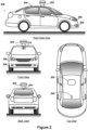
- FIG 2 depicts an example physical configuration of vehicle 200, which may represent one possible physical configuration of vehicle 100 described in reference to Figure 1 .
- vehicle 200 may include sensor unit 202, wireless communication system 204, radio unit 206, and camera 210, among other possible components.
- vehicle 200 may include some or all of the elements of components described in Figure 1 .
- vehicle 200 is depicted in Figure 2 as a car, vehicle 200 can have other configurations within examples, such as a truck, a van, a semi-trailer truck, a motorcycle, a golf cart, an off-road vehicle, or a farm vehicle, among other possible examples.
- Sensor unit 202 may include one or more sensors configured to capture information of the surrounding environment of vehicle 200.
- sensor unit 202 may include any combination of cameras, radars, LIDARs, range finders, radio devices (e.g., Bluetooth and/or 802.11), and acoustic sensors, among other possible types of sensors.
- sensor unit 202 may include one or more movable mounts operable to adjust the orientation of sensors in sensor unit 202.
- the movable mount may include a rotating platform that can scan sensors so as to obtain information from each direction around the vehicle 200.
- the movable mount of sensor unit 202 may also be moveable in a scanning fashion within a particular range of angles and/or azimuths.
- sensor unit 202 may include mechanical structures that enable sensor unit 202 to be mounted atop the roof of a car. Additionally, other mounting locations are possible within various examples.
- Wireless communication system 204 may have a location relative to vehicle 200 as depicted in Figure 2 , but can also have different locations within implementations.
- Wireless communication system 200 may include one or more wireless transmitters and one or more receivers that may communicate with other external or internal devices.
- wireless communication system 204 may include one or more transceivers for communicating with a user's device, other vehicles, and roadway elements (e.g., signs, traffic signals), among other possible entities.
- vehicle 200 may include one or more vehicular communication systems for facilitating communications, such as dedicated short-range communications (DSRC), radio frequency identification (RFID), and other proposed communication standards directed towards intelligent transport systems.
- DSRC dedicated short-range communications
- RFID radio frequency identification
- Camera 210 may have various positions relative to vehicle 200, such as a location on a front windshield of vehicle 200. As such, camera 210 may capture images of the environment of vehicle 200. As illustrated in Figure 2 , camera 210 may capture images from a forward-looking view with respect to vehicle 200, but other mounting locations (including movable mounts) and viewing angles of camera 210 are possible within implementations. In some examples, camera 210 may correspond to one or more visible light cameras. Alternatively or additionally, camera 210 may include infrared sensing capabilities. Camera 210 may also include optics that may provide an adjustable field of view.
- Figure 3A illustrates a block diagram of a sensing system 300 including a coupler 306.
- the coupler 306 may be configured to couple a sensor unit 304 to a vehicle 302.
- the coupler 306 may enable the sensor unit 304 to be removeably coupled to the vehicle 302.
- a vehicle may be sold as "autonomous ready.”
- An "autonomous ready" vehicle may be able to perform autonomous driving functions, but may lack some of the sensors used to perform autonomous driving functions.
- the vehicle 302 may include a coupler 306 that allows a sensor unit 304 to be coupled to the vehicle 302 later.
- a person may purchase an "autonomous ready" vehicle and may later decide to either buy or rent a sensor unit 304 in order to provide the vehicle with autonomous functionality.
- the coupler 306 may be a universal, non-manufacturer specific standardized design. That is, a sensor unit 304 may be coupled to any manufacturer's vehicle that is "autonomous ready.”
- an "autonomous ready" vehicle 302 may include a controller 320 that includes a processor 322 and a memory 324.
- the "autonomous ready” vehicle 302 may also include a power supply 326 and a heat unit 328.
- the controller 320 may be similar or the same as the computer system 112 of Figure 1 .
- the controller 320 may be configured to receive sensor data from the sensor unit 304 by way of a data bus 330 that passes through the coupler 306.
- the controller 320 may be able to determine control instructions for autonomous control of the vehicle based at least in part on the sensor data.
- the controller 320 may also store some data and/or control instructions in memory 324.
- the controller 320 may be a fully-functional controller that can perform all of the sensor processing on its own.
- the vehicle 302 may include a power supply 326.
- the power supply 326 may be similar or the same as power supply 110 described with respect to Figure 1 .
- the power supply 326 may provide a voltage (e.g., 12 volts) that supplies power to various components of the vehicle 302. In some instances, the power supply may be configured to provide other voltages than 12 volts.
- the power supply may be coupled to the sensor unit 304 by way of a power bus 332 that goes through the coupler 306.
- the vehicle 302 may include a heat unit 328.
- the heat unit 328 may be a radiator or other unit configured to provide cooling of various components of vehicle 302. In some various examples, the heat unit 328 may provide cooling based on air and/or liquid cooling.
- the heat unit 328 may be coupled to the sensor unit 304 by way of a heat bus 334 that passes through the coupler 306.
- the sensor unit 304 may contain various sensors, such as a LIDAR device 310, a RADAR device 312, and other sensing devices 314 (such as optical, acoustic, and/or other sensing devices) located in a housing 308.
- the housing 308 may be configured to couple to the vehicle 302 by way of the coupler 306.
- the sensors may be similar to those described throughout.
- the sensors may be coupled to the previously-described data bus that communicates sensor data to the controller 320 of the vehicle 302 through the coupler 306.
- the sensor unit may also include a heat exchanger 316.
- the heat exchanger 316 may be configured to provide cooling to the various sensors and components of the sensor unit 304.
- the heat exchanger 316 may use liquid cooling to remove heat from the various sensor devices during their operation.
- the LIDAR device 310 and/or the RADAR device 312 may generate heat during the operation.
- the heat exchanger 316 may be able to remove heat from the device(s).
- the heat unit 328 may be coupled to the sensor unit 302 by way of a heat bus that passes through the coupler 306. liquid, air, or other substance may flow through the heat bus to remove heat from the sensor unit.
- Figure 3B illustrates a block diagram of another sensing system 350 including a coupler 356.
- an "autonomous ready" vehicle may be able to perform autonomous driving functions, but may lack both some of the sensors used to perform autonomous driving functions as well as some of the processing power to perform autonomous driving functions. Similar to the example discussed with respect to Figure 3A , a person may purchase an "autonomous ready" vehicle 352. However, the "autonomous ready" vehicle 352 of Figure 3B may be a lower cost vehicle than that of Figure 3A . The lower cost "autonomous ready” vehicle 352 may not have sufficient processing capabilities for autonomous driving calculations. Thus, the controller 370 may not be able to make the determinations required based on sensor data to autonomously drive the vehicle. However, the controller 370 and processor 372 may be able to perform some control functions of the vehicle.
- the vehicle 352 may include a coupler 356 that allows other devices to be coupled to the vehicle 352 later.
- a person may purchase the "autonomous ready" vehicle 352 and later decide to either buy or rent a sensor unit 304 to provide the vehicle with autonomous functionality.
- the coupler 356 may be a universal, non-manufacturer specific standardized design. That is, a sensor unit 304 may be coupled to any manufacturer's vehicle that is "autonomous ready.”
- sensing system 350 may include a conversion unit 354.
- the conversion unit 354 may couple to the vehicle 352 by way of coupler 356 and to the sensor unit 304 by way of coupler 358.
- the conversion unit 354 may be integrated within the sensor unit 304 and the coupler 358 may be omitted.
- the conversion unit 354 may perform several functions to enable the vehicle 352 to perform autonomous driving functions.
- the conversion unit 354 may include a processor 362.
- the processor 362 may be configured to receive the sensor data from the data bus of the sensor unit.
- the processor 362 may also receive data from the controller 370 of the vehicle 352.
- the controller 370 may communicate signals related to the vehicle 352 to the processor 362.
- the controller 370 may be in communication and/or provide a connection to a control bus of the vehicle 352 to the processor 362.
- the bus of the vehicle 352 may be a Controller Area Network (CAN) bus in communication with an on-board vehicle diagnostic (OBD) system.
- the CAN bus may enable various units of the vehicle 352 to communicate with each other.
- the communication bus may be a bus other than a CAN bus.
- the processor 362 may be able to interpret sensor data from sensor unit 304 and vehicle data from vehicle 352 to determine a control scheme for the autonomous operation of the vehicle 352.
- the processor 362 may further be able to determine control signals for the vehicle 352.
- the processor 362 may communicate the control signals to the controller 370 of the vehicle 352 in order to autonomously operate the vehicle 352. Therefore, the processor 362 of the conversion unit 354 may perform autonomous driving calculations that would otherwise be performed by a processing unit of a vehicle.
- the processor 362 may be able to tap into the CAN bus (or other data bus) of the vehicle to provide autonomous operation.
- the conversion unit 354 may also contain a power converter 364.
- the power converter 364 may be able to convert a vehicle voltage to one or more voltages to power the various components of the sensor unit 304.
- the power converter 364 may receive one or more voltages from the vehicle 352 and convert them to one or more output voltages to the sensor unit 304.
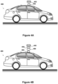
- Figure 4A depicts a physical configuration of a vehicle 400.
- the vehicle 400 may have a sensor unit 402 coupled to the top of the vehicle.
- the vehicle 400 may also have a coupler 404 that couples the sensor unit 402 and the vehicle 400.
- Figure 4B depicts a physical configuration of a vehicle 450.
- the vehicle 450 may have a sensor unit 452 coupled to a conversion unit 456 by way of a first coupler 454.
- the conversion unit 456 may coupled to the top of the vehicle 450 by a coupler 456.
- FIG. 5 is a flowchart of example method 500 for implementing a vehicle system.
- Method 500 represents an example method that may include one or more operations, functions, or actions, as depicted by one or more of blocks 502 and 504, each of which may be carried out by any of the systems shown in Figures 1 , 2 , 3A , 3B , and 4 , among other possible systems.
- blocks 502 and 504 each of which may be carried out by any of the systems shown in Figures 1 , 2 , 3A , 3B , and 4 , among other possible systems.
- each block of the flowchart may represent a module, a segment, or a portion of program code, which includes one or more instructions executable by one or more processors for implementing specific logical functions or steps in the process.
- the program code may be stored on any type of computer readable medium, for example, such as a storage device including a disk or hard drive.
- each block may represent circuitry that is wired to perform the specific logical functions in the process.
- Alternative implementations are included within the scope of the example implementations of the present application in which functions may be executed out of order from that shown or discussed, including substantially concurrent or in reverse order, depending on the functionality involved, as would be understood by those reasonably skilled in the art.
- a computing system may cause a system to perform one or more blocks of method 500.
- method 500 includes providing a control system configured to provide autonomous control to a vehicle.
- the control system may be configured to control the vehicle in an autonomous mode.
- the control system may be configured to operate the throttle, brakes, steering, and other operations to control the vehicle.
- the control system may further include navigation capabilities.
- the navigation capabilities may enable the autonomous vehicle to plan a route of operation.
- the vehicle may also be "autonomous ready.”
- the "autonomous ready" vehicle may have the capabilities to operate itself, but it may not include sensing systems that may be used during the autonomous operation of the vehicle.
- the vehicle includes a processing system that can receive sensor data and interpret the sensor data to control the vehicle.
- the processing system may communicate instructions to the control system to operate the "autonomous ready" vehicle in an autonomous mode.
- the sensor data may include data from RADAR, LIDAR, optical, and/or other sensors.
- the processing system may be able to determined localization of the vehicle, as well as obstacles located near the vehicle. The processing system may use both the localization as well as obstacles in both route planning and control of the vehicle.
- the vehicle may not include a processing system that can receive and interpret the sensor data.
- an external processor may be provided to receive and interpret the sensor data.
- This external processor may be part of a conversion unit that is added to the vehicle.
- the external processor may communicate instructions to the control system of the "autonomous ready" vehicle to operate the "autonomous ready” vehicle in an autonomous mode.
- the sensor data may include data from RADAR, LIDAR, optical, and/or other sensors.
- the external processor may be able to determined localization of the vehicle, as well as obstacles located near the vehicle.
- the external processor may use both the localization as well as obstacles in both route planning and control of the vehicle. Further, the external processor may be able to communicate with the control system of "autonomous ready" vehicle by way a data bus of the vehicle.
- method 500 includes providing a connector coupled to a roof of the vehicle configured to enable a sensor unit to couple to the vehicle.
- the connector may enable a sensor unit to be coupled to the top of the "autonomous ready” vehicle.
- the sensor unit may provide sensors that enable the "autonomous ready” vehicle to function in a fully autonomous mode.
- the connector may be a universal connector.
- a universal connector may be used by various vehicle manufacturer that build "autonomous ready” vehicles. By using a universal connector, a sensor unit may be coupled to "autonomous ready” vehicles from any manufacturer to enable autonomous functionality.
- the connector may provide various connections between the "autonomous ready" vehicle and the sensor unit.
- the connector may provide a data connection.
- the data connection may provide sensor data from the sensor unit to the vehicle.
- the sensor unit may be coupled to or include a conversion unit.
- the connector may receive control signals from the conversion unit.
- the control signals may be instructions for the autonomous operation of the vehicle.
- the connector may also provide power and heat exchanging to the sensor unit.
- the connector may include a voltage that transmits power to the sensor unit when the sensor unit is coupled to the vehicle.
- the connector may provide a 12-volt (or other voltage) connection to the sensor unit.
- the sensor unit or conversion unit may also include voltage conversion that provides appropriate voltages for the various components of the sensor unit.
- the connector may be configured to provide heat exchanging to the sensor unit. The heat exchanging may be performed by air, liquid, or other heat exchange means. During the operation of the sensor unit, heat may be generated. It may be desirable for the heat to be removed from the sensor unit.
- the vehicle may be configured with a radiator or other type of heat dissipation component that is connected to the heat exchanging portion of the connector.
- Figure 6 is a schematic illustrating a conceptual partial view of an example computer program product that includes a computer program for executing a computer process on a computing device, arranged according to at least some embodiments presented herein.
- the disclosed methods may be implemented as computer program instructions encoded on a non-transitory computer-readable storage media in a machine-readable format, or on other non-transitory media or articles of manufacture.
- example computer program product 600 is provided using signal bearing medium 602, which may include one or more programming instructions 604 that, when executed by one or more processors may provide functionality or portions of the functionality described above with respect to Figures 1-6 .
- the signal bearing medium 602 may encompass a non-transitory computer-readable medium 606, such as, but not limited to, a hard disk drive, a Compact Disc (CD), a Digital Video Disk (DVD), a digital tape, memory, etc.
- the signal bearing medium 602 may encompass a computer recordable medium 608, such as, but not limited to, memory, read/write (R/W) CDs, R/W DVDs, etc.
- the signal bearing medium 602 may encompass a communications medium 610, such as, but not limited to, a digital and/or an analog communication medium (e.g., a fiber optic cable, a waveguide, a wired communications link, a wireless communication link, etc.).
- the signal bearing medium 602 may correspond to a remote storage (e.g., a cloud).
- a computing system may share information with the cloud, including sending or receiving information.
- the computing system may receive additional information from the cloud to augment information obtained from sensors or another entity.
- the signal bearing medium 602 may be conveyed by a wireless form of the communications medium 610.
- the one or more programming instructions 604 may be, for example, computer executable and/or logic implemented instructions.
- a computing device such as the computer system 112 of Figure 1 may be configured to provide various operations, functions, or actions in response to the programming instructions 604 conveyed to the computer system 112 by one or more of the computer readable medium 606, the computer recordable medium 608, and/or the communications medium 610.
- the non-transitory computer readable medium could also be distributed among multiple data storage elements and/or cloud (e.g., remotely), which could be remotely located from each other.
- the computing device that executes some or all of the stored instructions could be a vehicle, such as the vehicle 200 illustrated in Figure 2 .
- the computing device that executes some or all of the stored instructions could be another computing device, such as a server.
Landscapes
- Engineering & Computer Science (AREA)
- Mechanical Engineering (AREA)
- Physics & Mathematics (AREA)
- Automation & Control Theory (AREA)
- Radar, Positioning & Navigation (AREA)
- Remote Sensing (AREA)
- General Physics & Mathematics (AREA)
- Aviation & Aerospace Engineering (AREA)
- Transportation (AREA)
- Acoustics & Sound (AREA)
- Electromagnetism (AREA)
- Mathematical Physics (AREA)
- Human Computer Interaction (AREA)
- Traffic Control Systems (AREA)
- Business, Economics & Management (AREA)
- Health & Medical Sciences (AREA)
- Artificial Intelligence (AREA)
- Evolutionary Computation (AREA)
- Game Theory and Decision Science (AREA)
- Medical Informatics (AREA)
- Control Of Driving Devices And Active Controlling Of Vehicle (AREA)
Abstract
Description
- The present application claims priority to
U.S. Patent Application No. 15/363,212, filed on November 29, 2016 - Vehicles are often used for various tasks, such as for the transportation of people and goods throughout an environment. With advances in technology, some vehicles are configured with systems that enable the vehicles to operate in a partial or fully autonomous mode. When operating in a partial or fully autonomous mode, some or all of the navigation aspects of vehicle operation are controlled by a vehicle control system rather than a traditional human driver. Autonomous operation of a vehicle can involve systems sensing the vehicle's surrounding environment to enable a computing system to plan and safely execute navigating routes to reach desired destinations.
- Disclosed herein are example implementations of a vehicular system. An example vehicular system includes a control system configured to provide autonomous control to a vehicle. The vehicular system also includes a connector coupled to a roof of the vehicle configured to enable a sensor unit to couple to the vehicle. The connector includes a power supply connection and a data bus. The data bus may be coupled to the control system.
- In another aspect, an example sensor unit is provided. The sensor unit includes a plurality of sensors configured to sense an environment of a vehicle. The sensor unit also includes a coupling portion configured to couple the sensor unit to a vehicle. The coupling portion includes a power supply connection and a data bus. The data bus may be configured to provide information to a control system of the vehicle.
- In another aspect, an example method is provided. The method includes providing a control system configured to provide autonomous control to a vehicle. The method also includes providing a connector coupled to a roof of the vehicle configured to enable a sensor unit to couple to the vehicle. The connector includes a power supply connection and a data bus, where the data bus is coupled to the control system.
- In another aspect, disclosed herein are example implementations of a system for a vehicle radar system. An example system may include means for providing autonomous control to a vehicle. The system also includes means for coupling a sensor unit to a roof of the vehicle. The connector includes a power supply connection and a data bus, where the data bus is coupled to the control system.
- The foregoing summary is illustrative only and is not intended to be in any way limiting. In addition to the illustrative aspects, embodiments, and features described above, further aspects, embodiments, and features will become apparent by reference to the figures and the following detailed description.
-
-
Figure 1 is a functional block diagram illustrating an example vehicle. -
Figure 2 depicts an example physical configuration of a vehicle. -
Figure 3A illustrates a block diagram of a sensing system including a coupler. -
Figure 3B illustrates a block diagram of another sensing system including a coupler. -
Figure 4A depicts a physical configuration of a vehicle. -
Figure 4B depicts a physical configuration of a vehicle. -
Figure 5 is a flow chart of a method, according to an example embodiment. -
Figure 6 depicts a schematic diagram of an example computer program. - In the following detailed description, reference is made to the accompanying figures, which form a part hereof. In the figures, similar symbols typically identify similar components, unless context dictates otherwise. The illustrative embodiments described in the detailed description, figures, and claims are not meant to be limiting. Other embodiments may be utilized, and other changes may be made, without departing from the scope of the subject matter presented herein. It will be readily understood that the aspects of the present disclosure, as generally described herein, and illustrated in the figures, can be arranged, substituted, combined, separated, and designed in a wide variety of different configurations, all of which are explicitly contemplated herein.
- A radar system for a vehicle is often used to sense an environment in a forward direction of the vehicle. For example, the radar system may measure the distance between the vehicle and another vehicle navigating in front of the vehicle. Although this type of radar system may improve forward navigation for the vehicle, the radar system does not provide a 360-degree view of the vehicle's surrounding environment.
- A vehicle may have a top-mounted sensor unit. The sensor unit may include both RADAR and LIDAR sensors. In some examples, the sensor unit may include other sensors as well, such as cameras, etc. The sensor unit may be configured to be detachable from the vehicle. Thus, a vehicle may be equipped with a connector that allows a sensor unit to be connected to the vehicle in order to attach the sensors to the vehicle. The top-mounted sensor unit may use a standardized connection to the vehicle. The standardized connection may enable a sensor unit to be coupled to vehicles from various manufacturers. The connection may support cooling, power transmission, data transmission, and transmission of other sensor data (brakes, throttle, etc.). In some implementations, a universal interface may enable a sensor unit to be coupled to a wide range of vehicles.
- In some instances, a vehicle may be sold as "autonomous ready." An autonomous ready vehicle may have some of the capabilities to perform autonomous driving functions, but may lack some of the hardware to enable these functions. An autonomous ready vehicle may include a connector that allows the sensor unit to be coupled to the vehicle when autonomous functionality is desired.
- In one example, an autonomous ready vehicle may have the processing capability to perform autonomous functions, but lacks a sensor unit. In that case, a sensor can be coupled to the vehicle using a connector. In another example, the autonomous ready vehicle may have a data bus that would allow autonomous control, but lacks both sensing and processing capabilities. In that case, the sensor unit that can be coupled to the vehicle may also include a processing unit that can operate the vehicle autonomously. Additionally, the system may use the computational capability of the vehicle to do sensor fusion and calculations and responsively control the vehicle.
- A conversion unit may perform optional computation (if the vehicle is not equipped) and voltage conversion (if the vehicle as only a single voltage bus). The conversion unit may perform self-driving calculations, in full or in part. In some examples the conversion unit may take over autopilot or other driver assist functions. The conversion unit may be able to tap into the data bus of the vehicle as a third party expansion module. In another embodiment, e.g., for vehicles that do nott have sufficient computational resources, an intermediate computational module may be inserted between the sensor unit and the vehicle to enable additional computation capabilities.
- Example radar systems described herein may capture measurements of a vehicle's surroundings. In some instances, a computing system of a vehicle or a remote system may use the radar data to determine control operations, such as route navigation and obstacle avoidance. As a result, the radar system may enable a vehicle to operate in a partial or fully autonomous mode. For instance, an example radar system may also be configured to supplement other sensor systems of a vehicle within some implementations. In some implementations, the radar system may provide radar data to an interface that a driver may use to assist with navigating the vehicle.
- Referring now to the figures,
Figure 1 is a functional block diagram illustratingexample vehicle 100, which may be configured to operate fully or partially in an autonomous mode. More specifically,vehicle 100 may operate in an autonomous mode without human interaction through receiving control instructions from a computing system. As part of operating in the autonomous mode,vehicle 100 may use sensors to detect and possibly identify objects of the surrounding environment to enable safe navigation. In some implementations,vehicle 100 may also include subsystems that enable a driver to control operations ofvehicle 100. - As shown in
Figure 1 ,vehicle 100 may include various subsystems, such aspropulsion system 102,sensor system 104,control system 106, one ormore peripherals 108,power supply 110,computer system 112,data storage 114, anduser interface 116. In other examples,vehicle 100 may include more or fewer subsystems, which can each include multiple elements. The subsystems and components ofvehicle 100 may be interconnected in various ways. In addition, functions ofvehicle 100 described herein can be divided into additional functional or physical components, or combined into fewer functional or physical components within implementations. -
Propulsion system 102 may include one or more components operable to provide powered motion forvehicle 100 and can include an engine/motor 118, anenergy source 119, atransmission 120, and wheels/tires 121, among other possible components. For example, engine/motor 118 may be configured to convertenergy source 119 into mechanical energy and can correspond to one or a combination of an internal combustion engine, an electric motor, steam engine, or Stirling engine, among other possible options. For instance, in some implementations,propulsion system 102 may include multiple types of engines and/or motors, such as a gasoline engine and an electric motor. -
Energy source 119 represents a source of energy that may, in full or in part, power one or more systems of vehicle 100 (e.g., engine/motor 118). For instance,energy source 119 can correspond to gasoline, diesel, other petroleum-based fuels, propane, other compressed gas-based fuels, ethanol, solar panels, batteries, and/or other sources of electrical power. In some implementations,energy source 119 may include a combination of fuel tanks, batteries, capacitors, and/or flywheels. -
Transmission 120 may transmit mechanical power from engine/motor 118 to wheels/tires 121 and/or other possible systems ofvehicle 100. As such,transmission 120 may include a gearbox, a clutch, a differential, and a drive shaft, among other possible components. A drive shaft may include axles that connect to one or more wheels/tires 121. - Wheels/
tires 121 ofvehicle 100 may have various configurations within example implementations. For instance,vehicle 100 may exist in a unicycle, bicycle/motorcycle, tricycle, or car/truck four-wheel format, among other possible configurations. As such, wheels/tires 121 may connect tovehicle 100 in various ways and can exist in different materials, such as metal and rubber. -
Sensor system 104 can include various types of sensors, such as Global Positioning System (GPS) 122, inertial measurement unit (IMU) 124,radar 126, laser rangefinder /LIDAR 128,camera 130, steeringsensor 123, and throttle/brake sensor 125, among other possible sensors. In some implementations,sensor system 104 may also include sensors configured to monitor internal systems of the vehicle 100 (e.g., O2 monitor, fuel gauge, engine oil temperature, brake wear). -
GPS 122 may include a transceiver operable to provide information regarding the position ofvehicle 100 with respect to the Earth.IMU 124 may have a configuration that uses one or more accelerometers and/or gyroscopes and may sense position and orientation changes ofvehicle 100 based on inertial acceleration. For example,IMU 124 may detect a pitch and yaw of thevehicle 100 whilevehicle 100 is stationary or in motion. -
Radar 126 may represent one or more systems configured to use radio signals to sense objects, including the speed and heading of the objects, within the local environment ofvehicle 100. As such,radar 126 may include antennas configured to transmit and receive radio signals. In some implementations,radar 126 may correspond to a mountable radar system configured to obtain measurements of the surrounding environment ofvehicle 100. - Laser rangefinder /
LIDAR 128 may include one or more laser sources, a laser scanner, and one or more detectors, among other system components, and may operate in a coherent mode (e.g., using heterodyne detection) or in an incoherent detection mode.Camera 130 may include one or more devices (e.g., still camera or video camera) configured to capture images of the environment ofvehicle 100. -
Steering sensor 123 may sense a steering angle ofvehicle 100, which may involve measuring an angle of the steering wheel or measuring an electrical signal representative of the angle of the steering wheel. In some implementations, steeringsensor 123 may measure an angle of the wheels of thevehicle 100, such as detecting an angle of the wheels with respect to a forward axis of thevehicle 100.Steering sensor 123 may also be configured to measure a combination (or a subset) of the angle of the steering wheel, electrical signal representing the angle of the steering wheel, and the angle of the wheels ofvehicle 100. - Throttle/
brake sensor 125 may detect the position of either the throttle position or brake position ofvehicle 100. For instance, throttle/brake sensor 125 may measure the angle of both the gas pedal (throttle) and brake pedal or may measure an electrical signal that could represent, for instance, an angle of a gas pedal (throttle) and/or an angle of a brake pedal. Throttle/brake sensor 125 may also measure an angle of a throttle body ofvehicle 100, which may include part of the physical mechanism that provides modulation ofenergy source 119 to engine/motor 118 (e.g., a butterfly valve or carburetor). Additionally, throttle/brake sensor 125 may measure a pressure of one or more brake pads on a rotor ofvehicle 100 or a combination (or a subset) of the angle of the gas pedal (throttle) and brake pedal, electrical signal representing the angle of the gas pedal (throttle) and brake pedal, the angle of the throttle body, and the pressure that at least one brake pad is applying to a rotor ofvehicle 100. In other embodiments, throttle/brake sensor 125 may be configured to measure a pressure applied to a pedal of the vehicle, such as a throttle or brake pedal. -
Control system 106 may include components configured to assist in navigatingvehicle 100, such assteering unit 132,throttle 134,brake unit 136,sensor fusion algorithm 138,computer vision system 140, navigation /pathing system 142, andobstacle avoidance system 144. More specifically,steering unit 132 may be operable to adjust the heading ofvehicle 100, andthrottle 134 may control the operating speed of engine/motor 118 to control the acceleration ofvehicle 100.Brake unit 136 may deceleratevehicle 100, which may involve using friction to decelerate wheels/tires 121. In some implementations,brake unit 136 may convert kinetic energy of wheels/tires 121 to electric current for subsequent use by a system or systems ofvehicle 100. -
Sensor fusion algorithm 138 may include a Kalman filter, Bayesian network, or other algorithms that can process data fromsensor system 104. In some implementations,sensor fusion algorithm 138 may provide assessments based on incoming sensor data, such as evaluations of individual objects and/or features, evaluations of a particular situation, and/or evaluations of potential impacts within a given situation. -
Computer vision system 140 may include hardware and software operable to process and analyze images in an effort to determine objects, environmental objects (e.g., stop lights, road way boundaries, etc.), and obstacles. As such,computer vision system 140 may use object recognition, Structure from Motion (SFM), video tracking, and other algorithms used in computer vision, for instance, to recognize objects, map an environment, track objects, estimate the speed of objects, etc. - Navigation /
pathing system 142 may determine a driving path forvehicle 100, which may involve dynamically adjusting navigation during operation. As such, navigation /pathing system 142 may use data fromsensor fusion algorithm 138,GPS 122, and maps, among other sources to navigatevehicle 100.Obstacle avoidance system 144 may evaluate potential obstacles based on sensor data and cause systems ofvehicle 100 to avoid or otherwise negotiate the potential obstacles. - As shown in
Figure 1 ,vehicle 100 may also includeperipherals 108, such aswireless communication system 146,touchscreen 148,microphone 150, and/orspeaker 152.Peripherals 108 may provide controls or other elements for a user to interact withuser interface 116. For example,touchscreen 148 may provide information to users ofvehicle 100.User interface 116 may also accept input from the user viatouchscreen 148.Peripherals 108 may also enablevehicle 100 to communicate with devices, such as other vehicle devices. -
Wireless communication system 146 may wirelessly communicate with one or more devices directly or via a communication network. For example,wireless communication system 146 could use 3G cellular communication, such as CDMA, EVDO, GSM/GPRS, or 4G cellular communication, such as WiMAX or LTE. Alternatively,wireless communication system 146 may communicate with a wireless local area network (WLAN) using WiFi or other possible connections.Wireless communication system 146 may also communicate directly with a device using an infrared link, Bluetooth, or ZigBee, for example. Other wireless protocols, such as various vehicular communication systems, are possible within the context of the disclosure. For example,wireless communication system 146 may include one or more dedicated short-range communications (DSRC) devices that could include public and/or private data communications between vehicles and/or roadside stations. -
Vehicle 100 may includepower supply 110 for powering components.Power supply 110 may include a rechargeable lithium-ion or lead-acid battery in some implementations. For instance,power supply 110 may include one or more batteries configured to provide electrical power.Vehicle 100 may also use other types of power supplies. In an example implementation,power supply 110 andenergy source 119 may be integrated into a single energy source. -
Vehicle 100 may also includecomputer system 112 to perform operations, such as operations described therein. As such,computer system 112 may include at least one processor 113 (which could include at least one microprocessor) operable to executeinstructions 115 stored in a non-transitory computer readable medium, such asdata storage 114. In some implementations,computer system 112 may represent a plurality of computing devices that may serve to control individual components or subsystems ofvehicle 100 in a distributed fashion. - In some implementations,
data storage 114 may contain instructions 115 (e.g., program logic) executable byprocessor 113 to execute various functions ofvehicle 100, including those described above in connection withFigure 1 .Data storage 114 may contain additional instructions as well, including instructions to transmit data to, receive data from, interact with, and/or control one or more ofpropulsion system 102,sensor system 104,control system 106, andperipherals 108. - In addition to
instructions 115,data storage 114 may store data such as roadway maps, path information, among other information. Such information may be used byvehicle 100 andcomputer system 112 during the operation ofvehicle 100 in the autonomous, semi-autonomous, and/or manual modes. -
Vehicle 100 may includeuser interface 116 for providing information to or receiving input from a user ofvehicle 100.User interface 116 may control or enable control of content and/or the layout of interactive images that could be displayed ontouchscreen 148. Further,user interface 116 could include one or more input/output devices within the set ofperipherals 108, such aswireless communication system 146,touchscreen 148,microphone 150, andspeaker 152. -
Computer system 112 may control the function ofvehicle 100 based on inputs received from various subsystems (e.g.,propulsion system 102,sensor system 104, and control system 106), as well as fromuser interface 116. For example,computer system 112 may utilize input fromsensor system 104 in order to estimate the output produced bypropulsion system 102 andcontrol system 106. Depending upon the embodiment,computer system 112 could be operable to monitor many aspects ofvehicle 100 and its subsystems. In some embodiments,computer system 112 may disable some or all functions of thevehicle 100 based on signals received fromsensor system 104. - The components of
vehicle 100 could be configured to work in an interconnected fashion with other components within or outside their respective systems. For instance, in an example embodiment,camera 130 could capture a plurality of images that could represent information about a state of an environment ofvehicle 100 operating in an autonomous mode. The state of the environment could include parameters of the road on which the vehicle is operating. For example,computer vision system 140 may be able to recognize the slope (grade) or other features based on the plurality of images of a roadway. Additionally, the combination ofGPS 122 and the features recognized bycomputer vision system 140 may be used with map data stored indata storage 114 to determine specific road parameters. Further,radar unit 126 may also provide information about the surroundings of the vehicle. - In other words, a combination of various sensors (which could be termed input-indication and output-indication sensors) and
computer system 112 could interact to provide an indication of an input provided to control a vehicle or an indication of the surroundings of a vehicle. - In some embodiments,
computer system 112 may make a determination about various objects based on data that is provided by systems other than the radio system. For example,vehicle 100 may have lasers or other optical sensors configured to sense objects in a field of view of the vehicle.Computer system 112 may use the outputs from the various sensors to determine information about objects in a field of view of the vehicle, and may determine distance and direction information to the various objects.Computer system 112 may also determine whether objects are desirable or undesirable based on the outputs from the various sensors. - Although
Figure 1 shows various components ofvehicle 100, i.e.,wireless communication system 146,computer system 112,data storage 114, anduser interface 116, as being integrated into thevehicle 100, one or more of these components could be mounted or associated separately fromvehicle 100. For example,data storage 114 could, in part or in full, exist separate fromvehicle 100. Thus,vehicle 100 could be provided in the form of device elements that may be located separately or together. The device elements that make upvehicle 100 could be communicatively coupled together in a wired and/or wireless fashion. -
Figure 2 depicts an example physical configuration ofvehicle 200, which may represent one possible physical configuration ofvehicle 100 described in reference toFigure 1 . Depending on the embodiment,vehicle 200 may includesensor unit 202,wireless communication system 204,radio unit 206, andcamera 210, among other possible components. For instance,vehicle 200 may include some or all of the elements of components described inFigure 1 . Althoughvehicle 200 is depicted inFigure 2 as a car,vehicle 200 can have other configurations within examples, such as a truck, a van, a semi-trailer truck, a motorcycle, a golf cart, an off-road vehicle, or a farm vehicle, among other possible examples. -
Sensor unit 202 may include one or more sensors configured to capture information of the surrounding environment ofvehicle 200. For example,sensor unit 202 may include any combination of cameras, radars, LIDARs, range finders, radio devices (e.g., Bluetooth and/or 802.11), and acoustic sensors, among other possible types of sensors. In some implementations,sensor unit 202 may include one or more movable mounts operable to adjust the orientation of sensors insensor unit 202. For example, the movable mount may include a rotating platform that can scan sensors so as to obtain information from each direction around thevehicle 200. The movable mount ofsensor unit 202 may also be moveable in a scanning fashion within a particular range of angles and/or azimuths. - In some implementations,
sensor unit 202 may include mechanical structures that enablesensor unit 202 to be mounted atop the roof of a car. Additionally, other mounting locations are possible within various examples. -
Wireless communication system 204 may have a location relative tovehicle 200 as depicted inFigure 2 , but can also have different locations within implementations.Wireless communication system 200 may include one or more wireless transmitters and one or more receivers that may communicate with other external or internal devices. For example,wireless communication system 204 may include one or more transceivers for communicating with a user's device, other vehicles, and roadway elements (e.g., signs, traffic signals), among other possible entities. As such,vehicle 200 may include one or more vehicular communication systems for facilitating communications, such as dedicated short-range communications (DSRC), radio frequency identification (RFID), and other proposed communication standards directed towards intelligent transport systems. -
Camera 210 may have various positions relative tovehicle 200, such as a location on a front windshield ofvehicle 200. As such,camera 210 may capture images of the environment ofvehicle 200. As illustrated inFigure 2 ,camera 210 may capture images from a forward-looking view with respect tovehicle 200, but other mounting locations (including movable mounts) and viewing angles ofcamera 210 are possible within implementations. In some examples,camera 210 may correspond to one or more visible light cameras. Alternatively or additionally,camera 210 may include infrared sensing capabilities.Camera 210 may also include optics that may provide an adjustable field of view. -
Figure 3A illustrates a block diagram of asensing system 300 including acoupler 306. Thecoupler 306 may be configured to couple asensor unit 304 to avehicle 302. Thecoupler 306 may enable thesensor unit 304 to be removeably coupled to thevehicle 302. In some examples, as previously discussed, a vehicle may be sold as "autonomous ready." An "autonomous ready" vehicle may be able to perform autonomous driving functions, but may lack some of the sensors used to perform autonomous driving functions. However, thevehicle 302 may include acoupler 306 that allows asensor unit 304 to be coupled to thevehicle 302 later. For example, a person may purchase an "autonomous ready" vehicle and may later decide to either buy or rent asensor unit 304 in order to provide the vehicle with autonomous functionality. In some examples, thecoupler 306 may be a universal, non-manufacturer specific standardized design. That is, asensor unit 304 may be coupled to any manufacturer's vehicle that is "autonomous ready." - In one example, an "autonomous ready"
vehicle 302 may include acontroller 320 that includes aprocessor 322 and amemory 324. The "autonomous ready"vehicle 302 may also include apower supply 326 and aheat unit 328. Thecontroller 320 may be similar or the same as thecomputer system 112 ofFigure 1 . Thecontroller 320 may be configured to receive sensor data from thesensor unit 304 by way of adata bus 330 that passes through thecoupler 306. Thecontroller 320 may be able to determine control instructions for autonomous control of the vehicle based at least in part on the sensor data. Thecontroller 320 may also store some data and/or control instructions inmemory 324. In some examples, thecontroller 320 may be a fully-functional controller that can perform all of the sensor processing on its own. - Additionally, the
vehicle 302 may include apower supply 326. Thepower supply 326 may be similar or the same aspower supply 110 described with respect toFigure 1 . Thepower supply 326 may provide a voltage (e.g., 12 volts) that supplies power to various components of thevehicle 302. In some instances, the power supply may be configured to provide other voltages than 12 volts. The power supply may be coupled to thesensor unit 304 by way of apower bus 332 that goes through thecoupler 306. Additionally, thevehicle 302 may include aheat unit 328. Theheat unit 328 may be a radiator or other unit configured to provide cooling of various components ofvehicle 302. In some various examples, theheat unit 328 may provide cooling based on air and/or liquid cooling. Theheat unit 328 may be coupled to thesensor unit 304 by way of aheat bus 334 that passes through thecoupler 306. - The
sensor unit 304 may contain various sensors, such as aLIDAR device 310, aRADAR device 312, and other sensing devices 314 (such as optical, acoustic, and/or other sensing devices) located in a housing 308. The housing 308 may be configured to couple to thevehicle 302 by way of thecoupler 306. The sensors may be similar to those described throughout. The sensors may be coupled to the previously-described data bus that communicates sensor data to thecontroller 320 of thevehicle 302 through thecoupler 306. The sensor unit may also include aheat exchanger 316. Theheat exchanger 316 may be configured to provide cooling to the various sensors and components of thesensor unit 304. Theheat exchanger 316 may use liquid cooling to remove heat from the various sensor devices during their operation. For example, theLIDAR device 310 and/or theRADAR device 312 may generate heat during the operation. In order to keep the devices cool and to prevent their failures, theheat exchanger 316 may be able to remove heat from the device(s). Additionally, as previously discussed, in order to remove the accumulated heat from thesensor unit 304, theheat unit 328 may be coupled to thesensor unit 302 by way of a heat bus that passes through thecoupler 306. liquid, air, or other substance may flow through the heat bus to remove heat from the sensor unit. -
Figure 3B illustrates a block diagram of another sensing system 350 including acoupler 356. In some examples, an "autonomous ready" vehicle may be able to perform autonomous driving functions, but may lack both some of the sensors used to perform autonomous driving functions as well as some of the processing power to perform autonomous driving functions. Similar to the example discussed with respect toFigure 3A , a person may purchase an "autonomous ready" vehicle 352. However, the "autonomous ready" vehicle 352 ofFigure 3B may be a lower cost vehicle than that ofFigure 3A . The lower cost "autonomous ready" vehicle 352 may not have sufficient processing capabilities for autonomous driving calculations. Thus, the controller 370 may not be able to make the determinations required based on sensor data to autonomously drive the vehicle. However, the controller 370 andprocessor 372 may be able to perform some control functions of the vehicle. - Similar to
vehicle 302 ofFigure 3A , the vehicle 352 may include acoupler 356 that allows other devices to be coupled to the vehicle 352 later. For example, a person may purchase the "autonomous ready" vehicle 352 and later decide to either buy or rent asensor unit 304 to provide the vehicle with autonomous functionality. As previously discussed, thecoupler 356 may be a universal, non-manufacturer specific standardized design. That is, asensor unit 304 may be coupled to any manufacturer's vehicle that is "autonomous ready." - In order to provide autonomous vehicle control, sensing system 350 may include a conversion unit 354. The conversion unit 354 may couple to the vehicle 352 by way of
coupler 356 and to thesensor unit 304 by way ofcoupler 358. In some further examples, the conversion unit 354 may be integrated within thesensor unit 304 and thecoupler 358 may be omitted. - The conversion unit 354 may perform several functions to enable the vehicle 352 to perform autonomous driving functions. In some examples, the conversion unit 354 may include a processor 362. The processor 362 may be configured to receive the sensor data from the data bus of the sensor unit. The processor 362 may also receive data from the controller 370 of the vehicle 352. The controller 370 may communicate signals related to the vehicle 352 to the processor 362. The controller 370 may be in communication and/or provide a connection to a control bus of the vehicle 352 to the processor 362. The bus of the vehicle 352 may be a Controller Area Network (CAN) bus in communication with an on-board vehicle diagnostic (OBD) system. The CAN bus may enable various units of the vehicle 352 to communicate with each other. In some other examples, the communication bus may be a bus other than a CAN bus.
- The processor 362 may be able to interpret sensor data from
sensor unit 304 and vehicle data from vehicle 352 to determine a control scheme for the autonomous operation of the vehicle 352. The processor 362 may further be able to determine control signals for the vehicle 352. The processor 362 may communicate the control signals to the controller 370 of the vehicle 352 in order to autonomously operate the vehicle 352. Therefore, the processor 362 of the conversion unit 354 may perform autonomous driving calculations that would otherwise be performed by a processing unit of a vehicle. Thus, the processor 362 may be able to tap into the CAN bus (or other data bus) of the vehicle to provide autonomous operation. - The conversion unit 354 may also contain a power converter 364. The power converter 364 may be able to convert a vehicle voltage to one or more voltages to power the various components of the
sensor unit 304. The power converter 364 may receive one or more voltages from the vehicle 352 and convert them to one or more output voltages to thesensor unit 304. -
Figure 4A depicts a physical configuration of avehicle 400. Thevehicle 400 may have asensor unit 402 coupled to the top of the vehicle. Thevehicle 400 may also have acoupler 404 that couples thesensor unit 402 and thevehicle 400.Figure 4B depicts a physical configuration of avehicle 450. Thevehicle 450 may have asensor unit 452 coupled to aconversion unit 456 by way of afirst coupler 454. Theconversion unit 456 may coupled to the top of thevehicle 450 by acoupler 456. -
Figure 5 is a flowchart ofexample method 500 for implementing a vehicle system.Method 500 represents an example method that may include one or more operations, functions, or actions, as depicted by one or more ofblocks Figures 1 ,2 ,3A ,3B , and4 , among other possible systems. Those skilled in the art will understand that the flowchart described herein illustrates functionality and operation of certain implementations of the present disclosure. In this regard, each block of the flowchart may represent a module, a segment, or a portion of program code, which includes one or more instructions executable by one or more processors for implementing specific logical functions or steps in the process. The program code may be stored on any type of computer readable medium, for example, such as a storage device including a disk or hard drive. - In addition, each block may represent circuitry that is wired to perform the specific logical functions in the process. Alternative implementations are included within the scope of the example implementations of the present application in which functions may be executed out of order from that shown or discussed, including substantially concurrent or in reverse order, depending on the functionality involved, as would be understood by those reasonably skilled in the art. In examples, a computing system may cause a system to perform one or more blocks of
method 500. - At
block 502,method 500 includes providing a control system configured to provide autonomous control to a vehicle. As previously discussed, the control system may be configured to control the vehicle in an autonomous mode. The control system may be configured to operate the throttle, brakes, steering, and other operations to control the vehicle. In some examples, the control system may further include navigation capabilities. The navigation capabilities may enable the autonomous vehicle to plan a route of operation. The vehicle may also be "autonomous ready." The "autonomous ready" vehicle may have the capabilities to operate itself, but it may not include sensing systems that may be used during the autonomous operation of the vehicle. - In a first example of an "autonomous ready" vehicle, the vehicle includes a processing system that can receive sensor data and interpret the sensor data to control the vehicle. When sensor data is interpreted, the processing system may communicate instructions to the control system to operate the "autonomous ready" vehicle in an autonomous mode. For example, the sensor data may include data from RADAR, LIDAR, optical, and/or other sensors. The processing system may be able to determined localization of the vehicle, as well as obstacles located near the vehicle. The processing system may use both the localization as well as obstacles in both route planning and control of the vehicle.
- In a second example of an "autonomous ready" vehicle, the vehicle may not include a processing system that can receive and interpret the sensor data. In these examples, an external processor may be provided to receive and interpret the sensor data. This external processor may be part of a conversion unit that is added to the vehicle. When sensor data is interpreted by the external processor of the conversion unit, the external processor may communicate instructions to the control system of the "autonomous ready" vehicle to operate the "autonomous ready" vehicle in an autonomous mode. The sensor data may include data from RADAR, LIDAR, optical, and/or other sensors. The external processor may be able to determined localization of the vehicle, as well as obstacles located near the vehicle. The external processor may use both the localization as well as obstacles in both route planning and control of the vehicle. Further, the external processor may be able to communicate with the control system of "autonomous ready" vehicle by way a data bus of the vehicle.
- At
block 504,method 500 includes providing a connector coupled to a roof of the vehicle configured to enable a sensor unit to couple to the vehicle. The connector may enable a sensor unit to be coupled to the top of the "autonomous ready" vehicle. The sensor unit may provide sensors that enable the "autonomous ready" vehicle to function in a fully autonomous mode. Additionally, the connector may be a universal connector. A universal connector may be used by various vehicle manufacturer that build "autonomous ready" vehicles. By using a universal connector, a sensor unit may be coupled to "autonomous ready" vehicles from any manufacturer to enable autonomous functionality. - The connector may provide various connections between the "autonomous ready" vehicle and the sensor unit. The connector may provide a data connection. In some examples, the data connection may provide sensor data from the sensor unit to the vehicle. In other examples, the sensor unit may be coupled to or include a conversion unit. In these examples, the connector may receive control signals from the conversion unit. The control signals may be instructions for the autonomous operation of the vehicle.
- The connector may also provide power and heat exchanging to the sensor unit. The connector may include a voltage that transmits power to the sensor unit when the sensor unit is coupled to the vehicle. In some examples, the connector may provide a 12-volt (or other voltage) connection to the sensor unit. The sensor unit or conversion unit may also include voltage conversion that provides appropriate voltages for the various components of the sensor unit. Additionally, the connector may be configured to provide heat exchanging to the sensor unit. The heat exchanging may be performed by air, liquid, or other heat exchange means. During the operation of the sensor unit, heat may be generated. It may be desirable for the heat to be removed from the sensor unit. The vehicle may be configured with a radiator or other type of heat dissipation component that is connected to the heat exchanging portion of the connector.
-
Figure 6 is a schematic illustrating a conceptual partial view of an example computer program product that includes a computer program for executing a computer process on a computing device, arranged according to at least some embodiments presented herein. In some embodiments, the disclosed methods may be implemented as computer program instructions encoded on a non-transitory computer-readable storage media in a machine-readable format, or on other non-transitory media or articles of manufacture. - In one embodiment, example
computer program product 600 is provided using signal bearing medium 602, which may include one ormore programming instructions 604 that, when executed by one or more processors may provide functionality or portions of the functionality described above with respect toFigures 1-6 . In some examples, the signal bearing medium 602 may encompass a non-transitory computer-readable medium 606, such as, but not limited to, a hard disk drive, a Compact Disc (CD), a Digital Video Disk (DVD), a digital tape, memory, etc. In some implementations, the signal bearing medium 602 may encompass acomputer recordable medium 608, such as, but not limited to, memory, read/write (R/W) CDs, R/W DVDs, etc. In some implementations, the signal bearing medium 602 may encompass acommunications medium 610, such as, but not limited to, a digital and/or an analog communication medium (e.g., a fiber optic cable, a waveguide, a wired communications link, a wireless communication link, etc.). Similarly, the signal bearing medium 602 may correspond to a remote storage (e.g., a cloud). A computing system may share information with the cloud, including sending or receiving information. For example, the computing system may receive additional information from the cloud to augment information obtained from sensors or another entity. Thus, for example, the signal bearing medium 602 may be conveyed by a wireless form of thecommunications medium 610. - The one or
more programming instructions 604 may be, for example, computer executable and/or logic implemented instructions. In some examples, a computing device such as thecomputer system 112 ofFigure 1 may be configured to provide various operations, functions, or actions in response to theprogramming instructions 604 conveyed to thecomputer system 112 by one or more of the computerreadable medium 606, thecomputer recordable medium 608, and/or thecommunications medium 610. - The non-transitory computer readable medium could also be distributed among multiple data storage elements and/or cloud (e.g., remotely), which could be remotely located from each other. The computing device that executes some or all of the stored instructions could be a vehicle, such as the
vehicle 200 illustrated inFigure 2 . Alternatively, the computing device that executes some or all of the stored instructions could be another computing device, such as a server. - The above detailed description describes various features and functions of the disclosed systems, devices, and methods with reference to the accompanying figures. While various aspects and embodiments have been disclosed herein, other aspects and embodiments will be apparent. The various aspects and embodiments disclosed herein are for purposes of illustration and are not intended to be limiting, with the true scope being indicated by the following claims.
- This specification includes the following clauses:
- 1. A vehicular system comprising:
- a control system configured to provide autonomous control to a vehicle; and
- a connector coupled to a roof of the vehicle configured to enable a sensor unit to couple to the vehicle, wherein the connector comprises:
- a power supply connection; and
- a data bus, wherein the data bus is coupled to the control system.
- 2. The vehicular system of clause 1, wherein the connector further comprises a thermal connection configured to remove heat from the sensor unit.
- 3. The vehicular system of clause 1, wherein the data bus is configured to provide vehicular control instructions from the sensor unit to the control system.
- 4. The vehicular system of clause 1, wherein the data bus is configured to provide sensor data from the sensor unit to the control system.
- 5. The vehicular system of clause 1, further comprising a conversion unit configured to:
- determine an object in an environment of the vehicle; and
- communicate control signals to the vehicle by way of the data bus, wherein the control signals are based on the determined object
- 6. The vehicular system of clause 5, wherein the conversion unit is further configured to convert a voltage provided by the power supply connection to at least one voltage of the sensor unit.
- 7. The vehicular system of clause 1, wherein the connector is configured to removably couple the sensor unit to the vehicle.
- 8. A sensor unit comprising:
- a plurality of sensors configured to sense an environment of a vehicle; and
- a coupling portion of the sensor unit configured to couple the sensor unit to the vehicle, the coupling portion comprising:
- a power supply connection; and
- a data bus, wherein the data bus is configured to provide information to a control system of the vehicle.
- 9. The sensor unit of clause 8, further comprising a conversion unit configured to:
determine an object in the environment of the vehicle; and
communicate control signals to the vehicle by way of the data bus, wherein the control signals are based on the determined object. - 10. The sensor unit of clause 9, wherein the conversion unit is further configured to convert a voltage provided by the power supply connection to at least one voltage of the sensor unit.
- 11. The sensor unit of clause 8, wherein the coupling portion is configured to removably couple the sensor unit to the vehicle.
- 12. The sensor unit of clause 8, wherein the coupling portion further comprises a thermal connection configured to remove heat from the sensor unit.
- 13. The sensor unit of clause 8, wherein the data bus is configured to provide vehicular control instructions from the sensor unit to the control system of the vehicle.
- 14. The sensor unit of clause 8, wherein the data bus is configured to provide sensor data from the sensor unit to the control system of the vehicle.
- 15. A method comprising:
- providing a control system configured to provide autonomous control to a vehicle; and
- providing a connector coupled to a roof of the vehicle configured to enable a sensor unit to couple to the vehicle, wherein the connector comprises:
- a power supply connection; and
- a data bus, wherein the data bus is coupled to the control system.
- 16. The method of clause 15, further comprising providing a conversion unit configured to:
- determine an object in an environment of the vehicle; and
- communicate control signals to the vehicle by way of the data bus, wherein the control signals are based on the determined object.
- 17. The method of
clause 16, wherein the conversion unit is further configured to convert a voltage provided by the power supply connection to at least one voltage of the sensor unit. - 18. The method of clause 15, further comprising providing a thermal connection configured to remove heat from the sensor unit.
- 19. The method of clause 15, wherein the data bus is configured to provide vehicular control instructions from the sensor unit to the control system of the vehicle.
- 20. The method of clause 15, wherein the data bus is configured to provide sensor data from the sensor unit to the control system of the vehicle.
Claims (15)
- A system (350) comprising:a control system (370) configured to autonomously control a vehicle (352); anda connector (356) coupled to the vehicle, wherein the connector is configured to enable a sensor unit (304) to be electrically connected to the vehicle, wherein the sensor unit generates sensor data representing an environment of the vehicle and includes a processor (362) configured to process the sensor data representing the environment, andwherein the connector comprises:a power supply connection (332); anda data bus (330) configured to connect to the control system and transmit data from the processor to the control system, wherein the data conveys a path for the vehicle to navigate.
- The system of claim 1, wherein the sensor unit comprises a radar unit (312),wherein the processor is configured to process radar data generated by the radar unit, andwherein the data bus is configured to transmit the processed radar data to the control system.
- The system of claim 1 or claim 2, wherein the data bus is further configured to:
provide processed sensor data from the sensor unit to the control system. - The system of claim 1, claim 2, or claim 3, further comprising:
a conversion unit (354) configured to convert a first voltage supplied by the power supply connection to a second voltage used by the sensor unit. - The system of any one of the preceding claims, wherein the sensor unit comprises one or more lidar units (310).
- The system of claim any one of the preceding claims, wherein the sensor unit comprises at least two types of sensors.
- The system of claim 6, wherein the at least two types of sensors comprises at least two of a lidar unit (310), a camera, and a radar unit (312).
- The system of claim 1, wherein the sensor unit comprises multiple cameras.
- A sensor unit (304) comprising:a first sensor positioned in a housing, wherein the first sensor is configured to generate sensor data representing an environment;a processor (362) configured to process the sensor data representing the environment; anda connector (356) configured to electrically couple the first sensor to a control system of a vehicle (352),wherein the connector comprises:a power supply connection (332); anda data bus (330) configured to connect to the control system (370) of the vehicle (352) and the first sensor, wherein the data bus enables the processor to communicate data to the control system, and wherein the data conveys a path for the vehicle to navigate.
- The sensor unit of claim 9, wherein the data bus is further configured to:
provide processed sensor data from the sensor unit to the control system. - The sensor unit of claim 9 or claim 10, further comprising:
a conversion unit (354) configured to convert a first voltage supplied by the power supply connection to a second voltage used by the first sensor. - The sensor unit of any one of claims 9 to 11, wherein the first sensor is a lidar unit (310), and wherein the sensor unit further comprises a camera or a radar (312).
- The sensor unit of any one of claims 9 to 11, wherein the first sensor is a lidar unit (310), andwherein the processor is configured to process lidar data generated by the lidar unit, andwherein the data bus is configured to transmit the processed lidar data to the control system.
- The sensor unit of any one of claims 9 to 11, wherein the first sensor is a first type of sensor, and wherein the sensor further comprises a second type of sensor.
- A non-transitory computer readable medium claim having stored therein instructions that, when executed by a computing system, cause the computing system to perform the method of any one of claims 1 to 8.
Applications Claiming Priority (3)
| Application Number | Priority Date | Filing Date | Title |
|---|---|---|---|
| US15/363,212 US20180150083A1 (en) | 2016-11-29 | 2016-11-29 | Pod connection for Autonomous Vehicle Sensors |
| PCT/US2017/063628 WO2018102363A1 (en) | 2016-11-29 | 2017-11-29 | Pod connection for autonomous vehicle sensors |
| EP17817520.4A EP3526078B1 (en) | 2016-11-29 | 2017-11-29 | Pod connection for autonomous vehicle sensors |
Related Parent Applications (1)
| Application Number | Title | Priority Date | Filing Date |
|---|---|---|---|
| EP17817520.4A Division EP3526078B1 (en) | 2016-11-29 | 2017-11-29 | Pod connection for autonomous vehicle sensors |
Publications (2)
| Publication Number | Publication Date |
|---|---|
| EP4552928A2 true EP4552928A2 (en) | 2025-05-14 |
| EP4552928A3 EP4552928A3 (en) | 2025-07-30 |
Family
ID=60703144
Family Applications (2)
| Application Number | Title | Priority Date | Filing Date |
|---|---|---|---|
| EP25166740.8A Pending EP4552928A3 (en) | 2016-11-29 | 2017-11-29 | Pod connection for autonomous vehicle sensors |
| EP17817520.4A Active EP3526078B1 (en) | 2016-11-29 | 2017-11-29 | Pod connection for autonomous vehicle sensors |
Family Applications After (1)
| Application Number | Title | Priority Date | Filing Date |
|---|---|---|---|
| EP17817520.4A Active EP3526078B1 (en) | 2016-11-29 | 2017-11-29 | Pod connection for autonomous vehicle sensors |
Country Status (6)
| Country | Link |
|---|---|
| US (1) | US20180150083A1 (en) |
| EP (2) | EP4552928A3 (en) |
| JP (1) | JP6835964B2 (en) |
| KR (2) | KR102377766B1 (en) |
| CN (1) | CN110023144A (en) |
| WO (1) | WO2018102363A1 (en) |
Families Citing this family (17)
| Publication number | Priority date | Publication date | Assignee | Title |
|---|---|---|---|---|
| US10150432B2 (en) * | 2017-03-20 | 2018-12-11 | Ford Global Technologies, Llc | Autonomous vehicle conversion |
| US10359303B1 (en) * | 2018-02-09 | 2019-07-23 | Ford Global Technologies, Llc | System for vehicle sensor assembly |
| CN110758400A (en) * | 2018-07-27 | 2020-02-07 | 郑州宇通客车股份有限公司 | Control method and device for intelligently driving vehicle |
| DK3849150T3 (en) | 2018-09-04 | 2023-04-03 | Byd Co Ltd | SECURE OPEN API FOR A VEHICLE |
| US10706619B2 (en) | 2018-09-12 | 2020-07-07 | Toyota Motor Engineering & Manufacturing North America, Inc. | Systems and methods for extending detachable automobile sensor capabilities for environmental mapping |
| US10730514B2 (en) * | 2018-09-12 | 2020-08-04 | Toyota Motor Engineering & Manufacturing North America, Inc. | Systems and methods for extending detachable automobile sensor capabilities for collision avoidance |
| US11240941B2 (en) * | 2018-09-12 | 2022-02-01 | Toyota Motor Engineering & Manufacturing North America, Inc. | Autonomous vehicle lidar cooling system |
| US11163312B2 (en) | 2018-11-02 | 2021-11-02 | Aurora Operations, Inc. | Removable automotive LIDAR data collection POD |
| US11408984B2 (en) | 2019-05-08 | 2022-08-09 | Ford Global Technologies, Llc | Sensor-drainage apparatus |
| US10632942B1 (en) * | 2019-09-30 | 2020-04-28 | Aurora Innovation, Inc. | Autonomous vehicle sensor interface |
| JP2021105602A (en) * | 2019-12-27 | 2021-07-26 | パイオニア株式会社 | Lidar device |
| US11522836B2 (en) * | 2020-02-25 | 2022-12-06 | Uatc, Llc | Deterministic container-based network configurations for autonomous vehicles |
| US11460546B2 (en) * | 2020-03-09 | 2022-10-04 | Ford Global Technologies, Llc | Sensor-drainage apparatus |
| USD1014398S1 (en) | 2021-12-23 | 2024-02-13 | Waymo Llc | Vehicle |
| USD1018337S1 (en) | 2021-12-23 | 2024-03-19 | Waymo Llc | Sensor assembly |
| JP7825525B2 (en) * | 2022-06-30 | 2026-03-06 | フォルシアクラリオン・エレクトロニクス株式会社 | Device control device and device control method |
| US12441255B2 (en) | 2022-12-15 | 2025-10-14 | Ford Global Technologies, Llc | Sensor assembly including mounting bracket fused to vehicle body |
Family Cites Families (19)
| Publication number | Priority date | Publication date | Assignee | Title |
|---|---|---|---|---|
| US5499182A (en) * | 1994-12-07 | 1996-03-12 | Ousborne; Jeffrey | Vehicle driver performance monitoring system |
| JPH08339864A (en) * | 1995-06-13 | 1996-12-24 | Fuji Facom Corp | Heat radiating connector |
| US6086131A (en) * | 1999-03-24 | 2000-07-11 | Donnelly Corporation | Safety handle for trunk of vehicle |
| US6789013B2 (en) * | 2001-04-24 | 2004-09-07 | Navman Nz Limited | Vehicle activity tracking |
| ITVI20020212A1 (en) * | 2002-10-15 | 2004-04-16 | Calearo Srl | VEHICLE ANTENNA WITH PERFECTED SHIELD. |
| US7191269B2 (en) * | 2003-07-30 | 2007-03-13 | Delphi Technologies, Inc. | Method for multiple sensors to communicate on a uni-directional bus |
| EP1508776A1 (en) * | 2003-08-18 | 2005-02-23 | Saab Ab | Autonomous velocity estimation and navigation |
| US20090152943A1 (en) * | 2007-12-17 | 2009-06-18 | Wael William Diab | Method and system for vehicular power distribution utilizing power over ethernet |
| US8126642B2 (en) * | 2008-10-24 | 2012-02-28 | Gray & Company, Inc. | Control and systems for autonomously driven vehicles |
| DE102009051605B4 (en) * | 2009-11-02 | 2022-08-18 | Continental Automotive Gmbh | Highly integrated multi-band fin antenna for a vehicle |
| CN102141621B (en) * | 2011-01-06 | 2015-05-06 | 同致电子科技(厦门)有限公司 | Method for positioning sensor of serial structural hostless parking radar system |
| US20120210730A1 (en) * | 2011-02-23 | 2012-08-23 | Raytheon Company | Method and Apparatus for Cooling a Vehicle Component |
| US8793046B2 (en) * | 2012-06-01 | 2014-07-29 | Google Inc. | Inferring state of traffic signal and other aspects of a vehicle's environment based on surrogate data |
| US9383753B1 (en) * | 2012-09-26 | 2016-07-05 | Google Inc. | Wide-view LIDAR with areas of special attention |
| US9121703B1 (en) * | 2013-06-13 | 2015-09-01 | Google Inc. | Methods and systems for controlling operation of a laser device |
| US9425654B2 (en) * | 2013-09-30 | 2016-08-23 | Google Inc. | Contactless electrical coupling for a rotatable LIDAR device |
| DE102015105528A1 (en) * | 2015-04-10 | 2016-10-13 | Connaught Electronics Ltd. | Camera for a motor vehicle with thermal connection device, driver assistance system, motor vehicle and method |
| CN204870799U (en) * | 2015-06-17 | 2015-12-16 | 深圳市金狼星电子有限公司 | Vehicle -mounted camera |
| US10288458B2 (en) * | 2016-06-29 | 2019-05-14 | GM Global Technology Operations LLC | Systems and methods for sensor platform |
-
2016
- 2016-11-29 US US15/363,212 patent/US20180150083A1/en not_active Abandoned
-
2017
- 2017-11-29 EP EP25166740.8A patent/EP4552928A3/en active Pending
- 2017-11-29 WO PCT/US2017/063628 patent/WO2018102363A1/en not_active Ceased
- 2017-11-29 EP EP17817520.4A patent/EP3526078B1/en active Active
- 2017-11-29 JP JP2019526311A patent/JP6835964B2/en active Active
- 2017-11-29 KR KR1020217019155A patent/KR102377766B1/en active Active
- 2017-11-29 CN CN201780073934.XA patent/CN110023144A/en active Pending
- 2017-11-29 KR KR1020197018484A patent/KR102269543B1/en not_active Expired - Fee Related
Also Published As
| Publication number | Publication date |
|---|---|
| EP4552928A3 (en) | 2025-07-30 |
| US20180150083A1 (en) | 2018-05-31 |
| KR20210079415A (en) | 2021-06-29 |
| KR20190085548A (en) | 2019-07-18 |
| KR102269543B1 (en) | 2021-06-29 |
| JP6835964B2 (en) | 2021-02-24 |
| EP3526078B1 (en) | 2025-04-16 |
| CN110023144A (en) | 2019-07-16 |
| EP3526078A1 (en) | 2019-08-21 |
| JP2020504690A (en) | 2020-02-13 |
| KR102377766B1 (en) | 2022-03-23 |
| WO2018102363A1 (en) | 2018-06-07 |
Similar Documents
| Publication | Publication Date | Title |
|---|---|---|
| EP3526078B1 (en) | Pod connection for autonomous vehicle sensors | |
| US11531353B2 (en) | Calculating velocity of an autonomous vehicle using radar technology | |
| US12561986B2 (en) | Vision-based indicator signal detection using spatiotemporal filtering | |
| CA3076834C (en) | Detecting motion of an autonomous vehicle using radar technology | |
| US12250476B2 (en) | Adjustable vertical field of view | |
| US20180113210A1 (en) | Mountable Radar System | |
| US10691135B2 (en) | Detecting motion of an autonomous vehicle using radar technology | |
| US12122364B2 (en) | Detection of pedestrian using radio devices | |
| US12501003B2 (en) | Multi-sensor assembly with improved backward view of a vehicle |
Legal Events
| Date | Code | Title | Description |
|---|---|---|---|
| PUAI | Public reference made under article 153(3) epc to a published international application that has entered the european phase |
Free format text: ORIGINAL CODE: 0009012 |
|
| STAA | Information on the status of an ep patent application or granted ep patent |
Free format text: STATUS: THE APPLICATION HAS BEEN PUBLISHED |
|
| AC | Divisional application: reference to earlier application |
Ref document number: 3526078 Country of ref document: EP Kind code of ref document: P |
|
| AK | Designated contracting states |
Kind code of ref document: A2 Designated state(s): AL AT BE BG CH CY CZ DE DK EE ES FI FR GB GR HR HU IE IS IT LI LT LU LV MC MK MT NL NO PL PT RO RS SE SI SK SM TR |
|
| REG | Reference to a national code |
Ref country code: DE Ref legal event code: R079 Free format text: PREVIOUS MAIN CLASS: B60R0016023000 Ipc: B60R0009000000 |
|
| PUAL | Search report despatched |
Free format text: ORIGINAL CODE: 0009013 |
|
| AK | Designated contracting states |
Kind code of ref document: A3 Designated state(s): AL AT BE BG CH CY CZ DE DK EE ES FI FR GB GR HR HU IE IS IT LI LT LU LV MC MK MT NL NO PL PT RO RS SE SI SK SM TR |
|
| RIC1 | Information provided on ipc code assigned before grant |
Ipc: B60R 9/00 20060101AFI20250623BHEP Ipc: B60R 16/023 20060101ALI20250623BHEP |
|
| STAA | Information on the status of an ep patent application or granted ep patent |
Free format text: STATUS: REQUEST FOR EXAMINATION WAS MADE |
|
| 17P | Request for examination filed |
Effective date: 20260127 |