EP4552905A2 - Schnellladestation für elektrofahrzeuge - Google Patents
Schnellladestation für elektrofahrzeuge Download PDFInfo
- Publication number
- EP4552905A2 EP4552905A2 EP24211622.6A EP24211622A EP4552905A2 EP 4552905 A2 EP4552905 A2 EP 4552905A2 EP 24211622 A EP24211622 A EP 24211622A EP 4552905 A2 EP4552905 A2 EP 4552905A2
- Authority
- EP
- European Patent Office
- Prior art keywords
- control unit
- power
- charging station
- module
- unit
- Prior art date
- Legal status (The legal status is an assumption and is not a legal conclusion. Google has not performed a legal analysis and makes no representation as to the accuracy of the status listed.)
- Withdrawn
Links
Images


Classifications
-
- B—PERFORMING OPERATIONS; TRANSPORTING
- B60—VEHICLES IN GENERAL
- B60L—PROPULSION OF ELECTRICALLY-PROPELLED VEHICLES; SUPPLYING ELECTRIC POWER FOR AUXILIARY EQUIPMENT OF ELECTRICALLY-PROPELLED VEHICLES; ELECTRODYNAMIC BRAKE SYSTEMS FOR VEHICLES IN GENERAL; MAGNETIC SUSPENSION OR LEVITATION FOR VEHICLES; MONITORING OPERATING VARIABLES OF ELECTRICALLY-PROPELLED VEHICLES; ELECTRIC SAFETY DEVICES FOR ELECTRICALLY-PROPELLED VEHICLES
- B60L53/00—Methods of charging batteries, specially adapted for electric vehicles; Charging stations or on-board charging equipment therefor; Exchange of energy storage elements in electric vehicles
- B60L53/60—Monitoring or controlling charging stations
- B60L53/67—Controlling two or more charging stations
-
- B—PERFORMING OPERATIONS; TRANSPORTING
- B60—VEHICLES IN GENERAL
- B60L—PROPULSION OF ELECTRICALLY-PROPELLED VEHICLES; SUPPLYING ELECTRIC POWER FOR AUXILIARY EQUIPMENT OF ELECTRICALLY-PROPELLED VEHICLES; ELECTRODYNAMIC BRAKE SYSTEMS FOR VEHICLES IN GENERAL; MAGNETIC SUSPENSION OR LEVITATION FOR VEHICLES; MONITORING OPERATING VARIABLES OF ELECTRICALLY-PROPELLED VEHICLES; ELECTRIC SAFETY DEVICES FOR ELECTRICALLY-PROPELLED VEHICLES
- B60L53/00—Methods of charging batteries, specially adapted for electric vehicles; Charging stations or on-board charging equipment therefor; Exchange of energy storage elements in electric vehicles
- B60L53/10—Methods of charging batteries, specially adapted for electric vehicles; Charging stations or on-board charging equipment therefor; Exchange of energy storage elements in electric vehicles characterised by the energy transfer between the charging station and the vehicle
- B60L53/11—DC charging controlled by the charging station, e.g. mode 4
-
- B—PERFORMING OPERATIONS; TRANSPORTING
- B60—VEHICLES IN GENERAL
- B60L—PROPULSION OF ELECTRICALLY-PROPELLED VEHICLES; SUPPLYING ELECTRIC POWER FOR AUXILIARY EQUIPMENT OF ELECTRICALLY-PROPELLED VEHICLES; ELECTRODYNAMIC BRAKE SYSTEMS FOR VEHICLES IN GENERAL; MAGNETIC SUSPENSION OR LEVITATION FOR VEHICLES; MONITORING OPERATING VARIABLES OF ELECTRICALLY-PROPELLED VEHICLES; ELECTRIC SAFETY DEVICES FOR ELECTRICALLY-PROPELLED VEHICLES
- B60L53/00—Methods of charging batteries, specially adapted for electric vehicles; Charging stations or on-board charging equipment therefor; Exchange of energy storage elements in electric vehicles
- B60L53/30—Constructional details of charging stations
-
- Y—GENERAL TAGGING OF NEW TECHNOLOGICAL DEVELOPMENTS; GENERAL TAGGING OF CROSS-SECTIONAL TECHNOLOGIES SPANNING OVER SEVERAL SECTIONS OF THE IPC; TECHNICAL SUBJECTS COVERED BY FORMER USPC CROSS-REFERENCE ART COLLECTIONS [XRACs] AND DIGESTS
- Y02—TECHNOLOGIES OR APPLICATIONS FOR MITIGATION OR ADAPTATION AGAINST CLIMATE CHANGE
- Y02T—CLIMATE CHANGE MITIGATION TECHNOLOGIES RELATED TO TRANSPORTATION
- Y02T10/00—Road transport of goods or passengers
- Y02T10/60—Other road transportation technologies with climate change mitigation effect
- Y02T10/70—Energy storage systems for electromobility, e.g. batteries
-
- Y—GENERAL TAGGING OF NEW TECHNOLOGICAL DEVELOPMENTS; GENERAL TAGGING OF CROSS-SECTIONAL TECHNOLOGIES SPANNING OVER SEVERAL SECTIONS OF THE IPC; TECHNICAL SUBJECTS COVERED BY FORMER USPC CROSS-REFERENCE ART COLLECTIONS [XRACs] AND DIGESTS
- Y02—TECHNOLOGIES OR APPLICATIONS FOR MITIGATION OR ADAPTATION AGAINST CLIMATE CHANGE
- Y02T—CLIMATE CHANGE MITIGATION TECHNOLOGIES RELATED TO TRANSPORTATION
- Y02T10/00—Road transport of goods or passengers
- Y02T10/60—Other road transportation technologies with climate change mitigation effect
- Y02T10/7072—Electromobility specific charging systems or methods for batteries, ultracapacitors, supercapacitors or double-layer capacitors
-
- Y—GENERAL TAGGING OF NEW TECHNOLOGICAL DEVELOPMENTS; GENERAL TAGGING OF CROSS-SECTIONAL TECHNOLOGIES SPANNING OVER SEVERAL SECTIONS OF THE IPC; TECHNICAL SUBJECTS COVERED BY FORMER USPC CROSS-REFERENCE ART COLLECTIONS [XRACs] AND DIGESTS
- Y02—TECHNOLOGIES OR APPLICATIONS FOR MITIGATION OR ADAPTATION AGAINST CLIMATE CHANGE
- Y02T—CLIMATE CHANGE MITIGATION TECHNOLOGIES RELATED TO TRANSPORTATION
- Y02T90/00—Enabling technologies or technologies with a potential or indirect contribution to GHG emissions mitigation
- Y02T90/10—Technologies relating to charging of electric vehicles
- Y02T90/12—Electric charging stations
-
- Y—GENERAL TAGGING OF NEW TECHNOLOGICAL DEVELOPMENTS; GENERAL TAGGING OF CROSS-SECTIONAL TECHNOLOGIES SPANNING OVER SEVERAL SECTIONS OF THE IPC; TECHNICAL SUBJECTS COVERED BY FORMER USPC CROSS-REFERENCE ART COLLECTIONS [XRACs] AND DIGESTS
- Y02—TECHNOLOGIES OR APPLICATIONS FOR MITIGATION OR ADAPTATION AGAINST CLIMATE CHANGE
- Y02T—CLIMATE CHANGE MITIGATION TECHNOLOGIES RELATED TO TRANSPORTATION
- Y02T90/00—Enabling technologies or technologies with a potential or indirect contribution to GHG emissions mitigation
- Y02T90/10—Technologies relating to charging of electric vehicles
- Y02T90/16—Information or communication technologies improving the operation of electric vehicles
Definitions
- the present invention relates to a rapid charging station for electric vehicles according to the preamble of claim 1 and a method for operating a rapid charging station according to the preamble of claim 11.
- Fast charging stations also known as high-performance chargers, are direct current charging stations for electric vehicles, particularly automobiles, but also trucks, ships, and the like. Fast charging stations are capable of completing a charging process of an electric vehicle in a comparatively short time, usually under an hour. It is therefore possible to carry out ten or more charging processes at a fast charging station in one day. However, this also means that a fast charging station can have longer idle times between charging processes and during off-peak times, especially at night. The standby consumption of a fast charging station has therefore long been a relevant selling point and must be taken into account when considering the total cost of ownership of a fast charging station. There is also a general trend towards less unnecessary use of resources, especially energy.
- the known state of the art (EP 3 506 471 A1 ), from which the invention is based, relates to a rapid charging station according to the preamble of claim 1.
- This rapid charging station has power modules that are assigned to connection points of the rapid charging station. If a power module is not required, this power module switches off an internal communication unit, a module control unit and other components.
- a central control unit of the rapid charging station can either directly control a switch in the power module or activate the internal voltage supply of the power module via a galvanically isolated communication line. This galvanic isolation between the central control unit and (some) internal components of the rapid charging station should be maintained for safety reasons.
- the problem is that the central control unit must send a wake-up signal to the power module via a galvanically isolated communication connection. This entails greater complexity, since standard communication connections are used as a connection between the The power module and the central control unit are omitted or additional components, possibly including the power supply, are required.
- the challenge is to make the known state of the art more efficient and cost-effective.
- the invention is based on the problem of designing and developing the known fast charging station in such a way that further optimization is achieved with regard to the aforementioned challenge.
- galvanic isolation is only installed behind a communication unit of the power module, allowing standard components to be used for communication if necessary, such as extremely energy-efficient CAN transceivers.
- This allows a communication network to be used for communication between the communication unit and the central control unit.
- the communication unit can then be powered externally from the power module, which offers various advantages. It is possible to supply multiple power modules with one power supply; this power supply can then switch off all power modules simultaneously and/or can also supply other components of the fast-charging station. Fewer components are required, and efficiency can be improved.
- the communication unit is galvanically isolated from the module control unit, that the rapid charging station has a power supply unit for providing an auxiliary voltage, which is arranged externally to the power module, that the communication unit is supplied with the auxiliary voltage by the power supply unit, that the communication unit is connected to the central control unit via a communication network, that in the standby state the communication unit assumes a sleep state, that in the standby state the communication unit can be woken up by the central control unit via the communication network, and that the communication unit activates the module control unit after being woken up by the central control unit.
- the communication units are preferably supplied with power jointly by the power supply, thus requiring fewer power supplies. If the power supply also supplies other components of the rapid charging station with power, it does not need to be put into standby mode.
- the power module can have an LV control unit and an HV control unit.
- LV stands for low volt and HV for high volt, but this refers to the assignment to areas of the power module.
- the HV control unit is thus assigned to a power electronics area of the power module, and the LV control unit is assigned to a galvanically isolated area, which is used in particular for communication and control purposes.
- the communication unit is arranged in the LV area. The galvanic isolation can therefore be easily implemented between the LV and HV areas.
- the communication network is a CAN bus.
- CAN transceivers with very low standby power are widely available.
- a CAN bus can be implemented robustly and cost-effectively even in the vicinity of larger electrical fields.
- Claims 5 to 7 relate to embodiments of the implementation of the standby state in relation to a charging process.
- the central control unit assigns power modules to the connection point, preferably as many as are available, and wakes them up (claim 5).
- some power modules can then be returned to the standby state and/or additional power modules can be woken up (claim 6).
- the central control unit can also predict a power increase and wake up another power module in time before the increased power is needed (claim 7). This allows the power modules to remain in standby mode for longer.
- Claim 8 specifies preferred embodiments of the standby state in the power module.
- an internal auxiliary power supply is provided in the power module.
- the separation between the HV and LV regions can be implemented such that the voltage of the power supply is significantly higher and only lower operating voltages are required internally, for example, for driver stages of the power converter arrangement.
- a further preferred embodiment relates to the possibility of switching off several power modules together via the power supply (claim 10).
- the communication unit is galvanically separated from the module control unit, that the rapid charging station has a power supply unit for providing an auxiliary voltage, which is arranged externally to the power module, that the communication unit is supplied with the auxiliary voltage by the power supply unit, that the communication unit is connected to the central control unit via a communication network, that in the standby state the communication unit assumes a sleep state, that in the standby state the communication unit can be woken up by the central control unit via the communication network, and that the communication unit activates the module control unit after being woken up by the central control unit.
- Fig. 1 shows an external view of a proposed rapid charging station 1 for electric vehicles.
- This station has at least one connection point 2 for an electric vehicle, in this case a permanently attached charging cable.
- the rapid charging station 1 has at least, in this case precisely two, connection points 2.
- a rapid charging station 1 is used to charge an electric vehicle using direct current and a power output of usually at least 50 kW.
- the rapid charging station 1 is typically connected to an alternating current network for this purpose.
- the rapid charging station 1 has at least one individually manageable power module 3.
- the rapid charging station 1 has seven power modules 3, each of which provides a portion of the total power of the rapid charging station 1, for example, 30 kW each.
- the power modules 3 can be distributed here, preferably flexibly, among the connection points 2.
- Power Module 3 for example, weighs approximately 39 kg, making it difficult to handle. However, it can be removed individually, and the components of Power Module 3 are not installed individually in Fast Charging Station 1.
- the exemplary embodiment shown in the figures and thus preferred relates to a rapid charging station 1 for electric vehicles.
- the rapid charging station 1 has a power module 3. Only one power module 3 will now be considered first; all statements regarding this power module 3 can apply accordingly to other power modules 3.
- the power module 3 has a power converter arrangement 4.
- the power converter arrangement 4 serves here and Preferably for converting a three-phase mains voltage as input voltage of the rapid charging station 1 into a direct voltage.
- DC voltage rails 5 can be seen for distributing the output power of the power modules 3 to the connection points 2.
- the alternating voltage input 6 is located in the lower area and in Fig. 1 and 2 not shown
- Fig. 3 shows some of the components of the power module 3, insofar as they are necessary for the present explanations.
- the power module 3 has a module control unit 7 for controlling the power converter arrangement 4.
- the power module 3 further has a communication unit 8.
- the power module 3 can be placed in a standby state in which the module control unit 7 is inactive. Inactive here and preferably means that the module control unit 7 is completely de-energized. Activating the module control unit 7 is then accompanied by connecting a voltage supply.
- the rapid charging station 1 has a central control unit 9.
- This central control unit 9 preferably communicates parameters for controlling the power converter arrangement 4 to the communication unit 8 and/or receives measured values from the communication unit 8. It can be provided that the communication unit 8 is the only communication unit 8 that communicates with any component outside the power module 3.
- the communication unit 8 is galvanically isolated from the module control unit 7. Furthermore, it is essential that the rapid charging station 1 has a power supply 10 for providing an auxiliary voltage, which is arranged externally to the power module 3, and that the communication unit 8 is supplied with the auxiliary voltage by the power supply 10.
- the communication unit 8 is connected to the central control unit 9 via a communication network 11.
- the communication unit 8 assumes a sleep state. Sleep states, e.g. known in English as sleep, deep sleep, low energy state, or the like, are generally known measures to reduce the standby consumption of components of any kind.
- the communication unit 8 can now Communication network 11 can be woken up by the central control unit 9. After being woken up by the central control unit 9, the communication unit 8 activates the module control unit 7.
- a communication network 11 is a network that actually provides a minimum level of network capability.
- the communication network 11 is a bus, for example, a CAN bus. Simple wiring without a communication protocol or the like is not considered a communication network 11.
- the rapid charging station 1 has at least two power modules 3, whose communication units 8 are able to communicate with the central control unit 9 and preferably with each other via the communication network 11.
- the communication units 8 are also supplied with the auxiliary voltage by the power supply 10.
- the power supply 10 is required for several, preferably all, power modules 3.
- additional components of the rapid charging station 1 that are not assigned to a power module 3 are supplied with the auxiliary voltage by the power supply 10.
- these can be additional control units of the rapid charging station 1 for connection points 2 and/or a display and/or a credit card terminal and/or LEDs or the like.
- the power module 3 has at least two galvanically isolated areas.
- the power module 3 has an LV control unit 12, which has the communication unit 8 or is connected to the communication unit 8.
- the LV control unit 12 and the communication unit 8 are preferably arranged together in an LV area 13, which has no galvanically isolated sub-areas 14.
- the LV area 13 is not galvanically isolated from the power supply unit 10 and/or the central control unit 9.
- the LV area 13 does not include any voltages greater than the auxiliary voltage and/or greater than 48 V, preferably 30 V.
- the auxiliary voltage of the power supply unit 10 is here and preferably 24 V.
- Communication with components outside of the power module 3 only takes place from the LV area 13.
- the module control unit 7 can be an HV control unit 15 that is galvanically isolated from the LV control unit 12.
- the HV control unit 15 is here and preferably arranged in an HV area 16 in which voltages greater than 50 V are also present.
- the HV area 16 can have galvanically isolated sub-areas 14.
- the HV area 16 has an AC/DC converter 17 and/or a DC/DC converter 18 and/or a DC/DC driver stage 19 for the DC/DC converter 18 and/or an AC/DC driver stage 20 for the AC/DC converter 17.
- the DC/DC converter 18 preferably isolates galvanically, here via a transformer 21.
- the communication unit 8 activates the LV control unit 12 or the LV control unit 12 otherwise if it is part of the LV control unit 12.
- the LV control unit 12 then preferably activates the HV control unit 15. It is preferably provided here that the LV control unit 12 and the HV control unit 15 communicate via an optocoupler.
- the communication network 11 is a CAN bus
- the communication unit 8 is a CAN transceiver.
- the CAN transceiver automatically terminates the sleep state when communicating on the CAN bus.
- the CAN transceiver is partially networking-capable, so that individual power modules 3 can be specifically awakened.
- the power module 3 does not provide power at a connection point 2 and does not receive any communication on the CAN bus, it automatically puts the power module 3 into standby mode after a predefined period of time.
- the rapid charging station 1 has at least two connection points 2 and that the power modules 3 can be flexibly assigned to the connection points 2. At least some power modules 3 can thus be assigned to one or the other connection point 2 as needed.
- the central control unit 9 assigns one or more power modules 3 to this connection point 2 and wakes up at least these, but preferably not all, power modules 3. Since it is not always clear at the start of the charging process what power is required, the central control unit 9 preferably wakes up more power modules 3 than necessary. In particular, the central control unit 9 wakes up all available power modules 3. In some cases, preferably not all of the woken up power modules 3 are subsequently involved in the charging process. It can be provided that at least one power module 3 assigned to the connection point 2 or temporarily assigned but with reference to the charging process is temporarily in the standby state during the charging process.
- the central control unit 9 detects a power requirement of the charging process and, based on the power requirement, adjusts the allocation of the power modules 3 to the connection point 2. The central control unit 9 performs the adjustment as needed.
- the central control unit 9 assigns another power module 3 to the connection point 2 depending on the power requirement, and/or the central control unit 9 cancels the assignment of a power module 3 to the connection point 2 depending on the power requirement.
- the former is particularly the case when the required power increases, the latter when it decreases.
- the power module 3 whose assignment has been cancelled goes into standby mode. Additionally or alternatively, the central control unit 9 the further power module 3 assigned to the connection point 2.
- the central control unit 9 Since a power module 3 is not instantly available when woken up, it is preferable for the central control unit 9 to derive a predicted, future, increased power demand based on the power demand and, based on the predicted power demand, to assign the additional power module 3 to the connection point 2 before the predicted power demand occurs, so that the wake-up of the power module 3 is completed before the future power demand is expected to occur.
- a wake-up time for this can be known to the central control unit 9. The prediction can be made by extrapolation, information from the electric vehicle, empirical values, or the like.
- the power converter arrangement 4 and/or the module control unit 7, in particular as HV control unit 15, and/or the LV control unit 12 is de-energized, preferably that in the standby state of all programmable logic circuits of the power module 3 in the standby state only the CAN transceiver is not de-energized.
- the power module 3 has an internal auxiliary voltage supply 26 that is galvanically isolated from the external power supply 10.
- the internal auxiliary voltage supply 26 is de-energized in the standby state, and/or the internal auxiliary voltage supply 26 has a voltage level of less than 75%, preferably less than 50%, of the power supply 10.
- the internal auxiliary voltage supply 26 has a voltage of 5 V or 3.3 V.
- the internal auxiliary voltage supply 26 is here and preferably assigned to the HV area 16.
- the rapid charging station 1 has an emergency circuit, in particular one implemented without programmable logic, which in the event of a fault implements an emergency shutdown of several power modules 3 by an emergency shutdown of the power supply unit 10.
- an emergency circuit in particular one implemented without programmable logic, which in the event of a fault implements an emergency shutdown of several power modules 3 by an emergency shutdown of the power supply unit 10.
- all of the power modules assigned to a connection point 2 or all Power modules 3 are emergency switched off by the power supply 10 in that the power supply 10 no longer provides the auxiliary voltage to the power modules 3.
- a method for operating a rapid charging station 1 is proposed, wherein the rapid charging station 1 has a power module 3, wherein the power module 3 has a power converter arrangement 4, in particular for converting an alternating voltage as input voltage of the rapid charging station 1 into a direct voltage as output voltage of the rapid charging station 1, wherein the power module 3 has a module control unit 7 for controlling the power converter arrangement 4, wherein the power module 3 has a communication unit 8, wherein the power module 3 can be put into a standby state in which the module control unit 7 is inactive, wherein the rapid charging station 1 has a central control unit 9.
- the communication unit 8 is galvanically separated from the module control unit 7, that the rapid charging station 1 has a power supply unit 10 for providing an auxiliary voltage, which is arranged externally to the power module 3, that the communication unit 8 is supplied with the auxiliary voltage by the power supply unit 10, that the communication unit 8 is connected to the central control unit 9 via a communication network 11, that in the standby state the communication unit 8 assumes a sleep state, that in the standby state the communication unit 8 can be woken up by the central control unit 9 via the communication network 11, and that the communication unit 8 activates the module control unit 7 after being woken up by the central control unit 9.
Landscapes
- Engineering & Computer Science (AREA)
- Power Engineering (AREA)
- Transportation (AREA)
- Mechanical Engineering (AREA)
- Charge And Discharge Circuits For Batteries Or The Like (AREA)
Abstract
Description
- Die vorliegende Erfindung betrifft eine Schnellladestation für Elektrofahrzeuge gemäß dem Oberbegriff von Anspruch 1 sowie ein Verfahren zum Betrieb einer Schnellladestation gemäß dem Oberbegriff von Anspruch 11.
- Schnellladestationen, auch bekannt als high performance charger, sind Gleichstromladestationen für elektrische Fahrzeuge, insbesondere Automobile, aber auch Lastkraftfahrzeuge, Schiffe und dergleichen. Schnellladestationen sind in der Lage, einen Ladevorgang eines Elektrofahrzeugs in vergleichsweise kurzer Zeit, regelmäßig unter einer Stunde, abzuschließen. Es ist daher möglich, an einer Schnellladestation an einem Tag zehn oder mehr Ladevorgänge durchzuführen. Das führt jedoch auch dazu, dass eine Schnellladestation zwischen den Ladevorgängen und außerhalb der Stoßzeiten, insbesondere nachts, längere Leerlaufzeiten aufweisen kann. Der Standbyverbrauch einer Schnellladestation ist daher längst ein relevantes Verkaufsargument und muss bei der Betrachtung der Gesamtbetriebskosten einer Schnellladestation berücksichtigt werden. Auch generell besteht ein Trend hin zu weniger unnötiger Verwendung von Ressourcen, insbesondere Energie.
- Der bekannte Stand der Technik (
EP 3 506 471 A1 ), von dem die Erfindung ausgeht, betrifft eine Schnellladestation gemäß dem Oberbegriff von Anspruch 1. Diese Schnellladestation weist Leistungsmodule auf, die Anschlusspunkten der Schnellladestation zugeordnet werden. Wird ein Leistungsmodul nicht benötigt, schaltet dieses Leistungsmodul eine interne Kommunikationseinheit, eine Modulsteuereinheit und weitere Komponenten ab. Eine zentrale Steuereinheit der Schnellladestation kann entweder einen Schalter im Leistungsmodul direkt ansteuern oder über eine galvanisch getrennte Kommunikationsleitung die interne Spannungsversorgung des Leistungsmoduls aktivieren. Diese galvanische Trennung zwischen zentraler Steuereinheit und (einigen) internen Komponenten der Schnellladestation soll aus Sicherheitsgründen beibehalten werden. Problematisch ist dann jedoch, dass die zentrale Steuereinheit ein Aufwecksignal über eine galvanisch getrennte Kommunikationsverbindung in das Leistungsmodul senden muss. Damit ist höherer Aufwand verbunden, da Standardkommunikationsverbindungen als Anbindung zwischen dem Leistungsmodul und der zentralen Steuereinheit entfallen oder weitere Komponenten, ggf. inklusive Energieversorgung, benötigt werden. - Es ist dabei eine Herausforderung, den bekannten Stand der Technik effizienter und kostengünstiger auszugestalten.
- Der Erfindung liegt das Problem zugrunde, die bekannte Schnellladestation derart auszugestalten und weiterzubilden, dass hinsichtlich der genannten Herausforderung eine weitere Optimierung erreicht wird.
- Das obige Problem wird durch die Merkmale des kennzeichnenden Teils von Anspruch 1 gelöst.
- Wesentlich ist die grundsätzliche Überlegung, dass eine galvanische Trennung erst hinter eine Kommunikationseinheit des Leistungsmoduls verlegt wird, wodurch bei Bedarf Standardkomponenten zur Kommunikation verwendet werden können, beispielsweise extrem energiesparende CAN-Transceiver. So kann ein Kommunikationsnetzwerk zur Kommunikation zwischen Kommunikationseinheit und zentraler Steuereinheit verwendet werden. Weiter kann die Kommunikationseinheit dann von extern des Leistungsmoduls mit Energie versorgt werden, wodurch diverse Vorteile entstehen. Es ist möglich, mehrere Leistungsmodule mit einem Netzteil zu versorgen, dieses Netzteil kann dann alle Leistungsmodule gleichzeitig abschalten und/oder kann auch weitere Komponenten der Schnellladestation versorgen. Es werden weniger Bauteile benötigt und die Effizienz kann verbessert werden.
- Im Einzelnen wird vorgeschlagen, dass die Kommunikationseinheit galvanisch von der Modulsteuereinheit getrennt ist, dass die Schnellladestation ein Netzteil zur Bereitstellung einer Hilfsspannung aufweist, das extern zu dem Leistungsmodul angeordnet ist, dass die Kommunikationseinheit von dem Netzteil mit der Hilfsspannung versorgt wird, dass die Kommunikationseinheit über ein Kommunikationsnetzwerk mit der zentralen Steuereinheit verbunden ist, dass in dem Standbyzustand die Kommunikationseinheit einen Schlafzustand einnimmt, dass im Standbyzustand die Kommunikationseinheit über das Kommunikationsnetzwerk von der zentralen Steuereinheit aufgeweckt werden kann, und, dass die Kommunikationseinheit nach ihrem Aufwecken durch die zentrale Steuereinheit die Modulsteuereinheit aktiviert.
- Bei einer bevorzugten Ausgestaltung gemäß Anspruch 2 ist vorgesehen, dass mehrere Leistungsmodule in das Kommunikationsnetzwerk eingebunden sind. Der Vorteil einer einfachen Netzwerkkommunikation wird so besonders klar. Die Kommunikationseinheiten werden vorzugsweise von dem Netzteil gemeinsam mit Energie versorgt, wodurch weniger Netzteile benötigt werden. Versorgt das Netzteil noch weitere Komponenten der Schnellladestation mit Energie, muss es auch nicht in Standby versetzt werden.
- Gemäß Anspruch 3 kann vorgesehen sein, dass das Leistungsmodul eine LV-Steuereinheit und eine HV-Steuereinheit aufweist. LV steht für low volt und HV für high volt, dabei geht es allerdings um die Zuordnung zu Bereichen des Leistungsmoduls, die HV-Steuereinheit ist also einem Leistungselektronikbereich des Leistungsmoduls zugeordnet und die LV Steuereinheit einem davon galvanisch getrennten Bereich, der insbesondere für Kommunikations- und Steuerzwecke genutzt wird. Im LV Bereich ist die Kommunikationseinheit angeordnet. Die galvanische Trennung kann daher einfach zwischen LV und HV Bereich umgesetzt sein.
- Bei einer bevorzugten Ausgestaltung gemäß Anspruch 4 ist das Kommunikationsnetzwerk ein CAN-Bus. CAN-Transceiver mit sehr geringem Standbyverbrauch sind weit erhältlich. Zusätzlich ist ein CAN-Bus auch in der Nähe größerer elektrischer Felder robust und günstig umsetzbar.
- Die Ansprüche 5 bis 7 betreffen Ausgestaltungen der Umsetzung des Standbyzustands im Verhältnis zu einem Ladevorgang. Grundsätzlich müssen nicht alle Leistungsmodule aufgeweckt werden, wenn nur einige benötigt werden. Allerdings steht zu Beginn eines Ladevorgangs die, möglicherweise schnell erreichte, Maximalleistung des Elektrofahrzeugs nicht immer fest. Daher wird vorgeschlagen, dass die zentrale Steuereinheit dem Anschlusspunkt Leistungsmodule zuordnet, vorzugsweise so viele wie verfügbar, und diese aufweckt (Anspruch 5). Während des Ladevorgangs können dann einige Leistungsmodule wieder in den Standbyzustand überführt und/oder weitere Leistungsmodule aufgeweckt werden (Anspruch 6). Die zentrale Steuereinheit kann außerdem eine Leistungserhöhung prädizieren und ein weiteres Leistungsmodul rechtzeitig aufwecken, bevor die erhöhte Leistung benötigt wird (Anspruch 7). So können die Leistungsmodule insgesamt länger im Standby verbleiben.
- Anspruch 8 gibt bevorzugte Ausgestaltungen des Standbyzustands im Leistungsmodul an. Bei einer Ausgestaltung gemäß Anspruch 9 ist vorgesehen, dass eine interne Hilfsspannungsversorgung im Leistungsmodul existiert. Die Trennung zwischen dem HV Bereich und dem LV Bereich kann dabei so umgesetzt sein, dass die Spannung des Netzteils wesentlich höher ist und intern nur noch geringere Betriebsspannungen benötigt werden, beispielsweise für Treiberstufen der Stromrichteranordnung.
- Eine weitere bevorzugte Ausgestaltung betrifft die Möglichkeit, mehrere Leistungsmodule gemeinsam über das Netzteil abzuschalten (Anspruch 10).
- Nach einer weiteren Lehre gemäß Anspruch 11, der eigenständige Bedeutung zukommt, wird ein Verfahren zum Betrieb einer Schnellladestation beansprucht.
- Dabei ist wesentlich, dass die Kommunikationseinheit galvanisch von der Modulsteuereinheit getrennt ist, dass die Schnellladestation ein Netzteil zur Bereitstellung einer Hilfsspannung aufweist, das extern zu dem Leistungsmodul angeordnet ist, dass die Kommunikationseinheit von dem Netzteil mit der Hilfsspannung versorgt wird, dass die Kommunikationseinheit über ein Kommunikationsnetzwerk mit der zentralen Steuereinheit verbunden ist, dass in dem Standbyzustand die Kommunikationseinheit einen Schlafzustand einnimmt, dass im Standbyzustand die Kommunikationseinheit über das Kommunikationsnetzwerk von der zentralen Steuereinheit aufgeweckt werden kann, und, dass die Kommunikationseinheit nach ihrem Aufwecken durch die zentrale Steuereinheit die Modulsteuereinheit aktiviert.
- Auf alle Ausführungen zu der vorschlagsgemäßen Schnellladestation darf verwiesen werden.
- Im Folgenden wird die Erfindung anhand einer lediglich Ausführungsbeispiele darstellenden Zeichnung näher erläutert. In der Zeichnung zeigt
- Fig. 1
- eine vorschlagsgemäße Schnellladestation,
- Fig. 2
- einen Blick in die Schnellladestation und auf die Leistungsmodule,
- Fig. 3
- Leistungsmodule sowie Kommunikations- und Leistungspfade und
-
Fig. 1 zeigt eine Außenansicht einer vorschlagsgemäßen Schnellladestation 1 für Elektrofahrzeuge. Diese weist mindestens einen Anschlusspunkt 2 für ein Elektrofahrzeug, hier ein fest angeschlagenes Ladekabel, auf. Vorzugsweise weist die Schnellladestation 1 mindestens, hier genau, zwei Anschlusspunkte 2 auf. Eine Schnellladestation 1 dient zum Laden eines Elektrofahrzeugs mittels Gleichstroms und einer Leistung von zumeist mindestens 50 kW. Üblicherweise ist die Schnellladestation 1 dafür an ein Wechselstromnetz angeschlossen. - Wie in der geöffneten Ansicht in
Fig. 2 erkennbar ist, weist die Schnellladestation 1 mindestens ein einzeln handhabbares Leistungsmodul 3 auf. Hier weist die Schnellladestation 1 sieben Leistungsmodule 3 auf, die jeweils einen Teil der Gesamtleistung der Schnellladestation 1 zur Verfügung stellen, hier beispielsweise jeweils 30 kW. Die Leistungsmodule 3 können hier und vorzugsweise flexibel auf die Anschlusspunkte 2 aufgeteilt werden. - Der Begriff "einzeln handhabbar" ist hier breit zu verstehen. Das Leistungsmodul 3 wiegt hier beispielsweise etwa 39 kg, ist also nicht leicht handhabbar. Es ist jedoch einzeln herausnehmbar und die Komponenten des Leistungsmoduls 3 sind gerade nicht einzeln in der Schnellladestation 1 verbaut.
- Das in den Figuren dargestellte und insoweit bevorzugte Ausführungsbeispiel betrifft eine Schnellladestation 1 für Elektrofahrzeuge. Die Schnellladestation 1 weist ein Leistungsmodul 3 auf. Betrachtet wird nun zuerst nur ein Leistungsmodul 3, alle Aussagen zu diesem Leistungsmodul 3 können für weitere Leistungsmodule 3 entsprechend gelten. Das Leistungsmodul 3 weist eine Stromrichteranordnung 4 auf. Die Stromrichteranordnung 4 dient hier und vorzugsweise zur Wandlung einer dreiphasigen Netzspannung als Eingangsspannung der Schnellladestation 1 in eine Gleichspannung. Erkennbar sind im oberen Bereich der Schnellladestation 1 Gleichspannungsschienen 5 zur Verteilung der Ausgangsleistung der Leistungsmodule 3 auf die Anschlusspunkte 2. Der Wechselspannungseingang 6 ist hier im unteren Bereich angeordnet und in
Figs. 1 und2 nicht dargestellt -
Fig. 3 zeigt einige der Komponenten des Leistungsmoduls 3, soweit diese für die vorliegenden Erläuterungen notwendig sind. Das Leistungsmodul 3 weist eine Modulsteuereinheit 7 zur Steuerung der Stromrichteranordnung 4 auf. Das Leistungsmodul 3 weist weiter eine Kommunikationseinheit 8 auf. Das Leistungsmodul 3 kann in einen Standbyzustand versetzt werden, in dem die Modulsteuereinheit 7 inaktiv ist. Inaktiv bedeutet hier und vorzugsweise, dass die Modulsteuereinheit 7 völlig stromlos ist. Ein Aktivieren der Modulsteuereinheit 7 geht dann mit einem Zuschalten einer Spannungsversorgung einher. - Weiter weist die Schnellladestation 1 eine zentrale Steuereinheit 9 auf. Diese kommuniziert hier und vorzugsweise Parameter zur Steuerung der Stromrichteranordnung 4 an die Kommunikationseinheit 8 und/oder erhält Messwerte von der Kommunikationseinheit 8. Es kann vorgesehen sein, dass die Kommunikationseinheit 8 die einzige Kommunikationseinheit 8 ist, die mit irgendeiner Komponente außerhalb des Leistungsmoduls 3 kommuniziert.
- Wesentlich ist nun, dass die Kommunikationseinheit 8 galvanisch von der Modulsteuereinheit 7 getrennt ist. Weiter ist wesentlich, dass die Schnellladestation 1 ein Netzteil 10 zur Bereitstellung einer Hilfsspannung aufweist, das extern zu dem Leistungsmodul 3 angeordnet ist, und, dass die Kommunikationseinheit 8 von dem Netzteil 10 mit der Hilfsspannung versorgt wird.
- Es ist vorgesehen, dass die Kommunikationseinheit 8 über ein Kommunikationsnetzwerk 11 mit der zentralen Steuereinheit 9 verbunden ist. In dem Standbyzustand nimmt die Kommunikationseinheit 8 einen Schlafzustand ein. Schlafzustände, bspw. auf Englisch bekannt als sleep, deep sleep, low energy state, oder dergleichen, sind grundsätzlich bekannte Maßnahmen, um den Standbyverbrauch von Komponenten jeglicher Art zu vermindern. Im Standbyzustand kann die Kommunikationseinheit 8 nun über das Kommunikationsnetzwerk 11 von der zentralen Steuereinheit 9 aufgeweckt werden. Nach ihrem Aufwecken durch die zentrale Steuereinheit 9 aktiviert die Kommunikationseinheit 8 die Modulsteuereinheit 7.
- Es darf hier angemerkt werden, dass ein Kommunikationsnetzwerk 11 ein Netzwerk ist, das tatsächlich ein Mindestmaß an Netzwerkfähigkeit mitbringt. Hier und vorzugsweise ist das Kommunikationsnetzwerk 11 ein Bus, beispielsweise CAN-Bus. Eine simple Verdrahtung ohne Kommunikationsprotokoll oder dergleichen wird nicht als Kommunikationsnetzwerk 11 angesehen.
- Hier und vorzugsweise ist vorgesehen, dass die Schnellladestation 1 mindestens zwei Leistungsmodule 3 aufweist, deren Kommunikationseinheiten 8 über das Kommunikationsnetzwerk 11 mit der zentralen Steuereinheit 9 und vorzugsweise einander kommunizieren sind.
- Hier und vorzugsweise ist es außerdem so, dass die Kommunikationseinheiten 8 von dem Netzteil 10 mit der Hilfsspannung versorgt werden. So wird nur ein Netzteil 10 für mehrere, vorzugsweise alle, Leistungsmodule 3 benötigt. Zusätzlich kann vorgesehen sein, dass weitere Komponenten der Schnellladestation 1, die keinem Leistungsmodul 3 zugeordnet sind, von dem Netzteil 10 mit der Hilfsspannung versorgt werden. Beispielhaft können das weitere Steuereinheiten der Schnellladestation 1 für Anschlusspunkte 2 und/oder ein Display und/oder ein Kreditkartenterminal und/oder LEDs oder dergleichen sein.
- Das Leistungsmodul 3 weist mindestens zwei galvanisch voneinander getrennte Bereiche auf. Hier und vorzugsweise weist das Leistungsmodul 3 eine LV-Steuereinheit 12 auf, die die Kommunikationseinheit 8 aufweist oder mit der Kommunikationseinheit 8 verbunden ist. Die LV-Steuereinheit 12 und die Kommunikationseinheit 8 sind vorzugsweise gemeinsam in einem LV-Bereich 13 angeordnet, der keine galvanisch getrennten Unterbereiche 14 aufweist. Weiter kann vorgesehen sein, dass der LV-Bereich 13 galvanisch nicht von dem Netzteil 10 und/oder der zentralen Steuereinheit 9 getrennt ist. Vorzugsweise umfasst der LV-Bereich 13 keine Spannungen größer als die Hilfsspannung und/oder größer als 48 V, vorzugsweise 30 V. Die Hilfsspannung des Netzteils 10 beträgt hier und vorzugsweise 24 V. Hier und vorzugsweise findet eine Kommunikation mit Komponenten außerhalb des Leistungsmoduls 3 nur aus dem LV-Bereich 13 heraus statt.
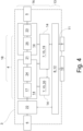
- Die Modulsteuereinheit 7 kann eine HV-Steuereinheit 15 sein, die galvanisch von der LV-Steuereinheit 12 getrennt ist. Die HV-Steuereinheit 15 ist hier und vorzugsweise in einem HV-Bereich 16 angeordnet, in dem auch Spannungen größer als 50 V vorhanden sind. Der HV-Bereich 16 kann galvanisch getrennte Unterbereiche 14 aufweisen. Hier und vorzugsweise weist der HV-Bereich 16 einen AC/DC Wandler 17 und/oder einen DC/DC Wandler 18 und/oder eine DC/DC Treiberstufe 19 für den DC/DC Wandler 18 und oder eine AC/DC Treiberstufe 20 für den AC/DC Wandler 17 auf. Der DC/DC Wandler 18 trennt vorzugsweise galvanisch, hier über einen Transformator 21. Diese Komponenten sowie die galvanisch getrennten Kommunikationen (gestrichelt) zeigt
Fig. 4 . Weiter zeigtFig. 4 eine Eingangsfilterstufe 22 und eine Ausgangsfilterstufe 23 sowie eine Eingangsseite 24 und eine Ausgangsseite 25 des DC/DC Wandlers 18. - Vorzugsweise aktiviert die Kommunikationseinheit 8 die LV-Steuereinheit 12 oder die LV-Steuereinheit 12 im Übrigen, falls sie Teil der LV-Steuereinheit 12 ist. Die LV-Steuereinheit 12 aktiviert dann vorzugsweise die HV-Steuereinheit 15. Es ist hier und vorzugsweise vorgesehen, dass die LV-Steuereinheit 12 und die HV-Steuereinheit 15 über einen Optokoppler kommunizieren.
- Weiter ist hier und vorzugsweise vorgesehen, dass das Kommunikationsnetzwerk 11 ein CAN-Bus ist, und, dass die Kommunikationseinheit 8 ein CAN-Transceiver ist. Vorzugsweise beendet der CAN-Transceiver den Schlafzustand bei Kommunikation auf dem CAN-Bus automatisch. Dabei kann vorgesehen sein, dass der CAN-Transceiver partial networking-fähig ist, sodass einzelne Leistungsmodule 3 gezielt aufgeweckt werden können.
- Unabhängig davon ist hier und vorzugsweise vorgesehen, dass das Leistungsmodul 3, wenn es keine Leistung an einem Anschlusspunkt 2 stellt und keine Kommunikation auf dem CAN-Bus empfängt, nach einer vordefinierten Zeitspanne automatisch das Leistungsmodul 3 in den Standbyzustand versetzt.
- Weiter ist hier und vorzugsweise vorgesehen, dass die Schnellladestation 1 mindestens zwei Anschlusspunkte 2 aufweist und dass die Leistungsmodule 3 den Anschlusspunkten 2 flexibel zuordenbar sind. Zumindest einige Leistungsmodule 3 können so nach Bedarf dem einen oder dem anderen Anschlusspunkt 2 zugeordnet werden.
- Zu Beginn eines Ladevorgangs an einem der Anschlusspunkte 2 ordnet die zentrale Steuereinheit 9 diesem Anschlusspunkt 2 ein oder mehrere Leistungsmodule 3 zu und weckt mindestens diese, vorzugsweise jedoch nicht alle, Leistungsmodule 3 auf. Da zu Beginn des Ladevorgangs nicht immer klar ist, welche Leistung benötigt wird, weckt die zentrale Steuereinheit 9 bevorzugt mehr Leistungsmodule 3 auf, als notwendig. Insbesondere weckt die zentrale Steuereinheit 9 alle verfügbaren Leistungsmodule 3 auf. In manchen Fällen sind dann vorzugsweise nicht alle der aufgeweckten Leistungsmodule 3 anschließend an dem Ladevorgang beteiligt. Es kann vorgesehen sein, dass mindestens ein dem Anschlusspunkt 2 zugeordnetes oder zeitweise, aber mit Bezug zu dem Ladevorgang, zugeordnetes Leistungsmodul 3 während des Ladevorgangs zeitweise im Standbyzustand ist.
- Weiter ist hier und vorzugsweise vorgesehen, dass nach Beginn, und vorzugsweise regelmäßig während, des Ladevorgangs die zentrale Steuereinheit 9 eine Leistungsanforderung des Ladevorgangs erfasst und basierend auf der Leistungsanforderung die Zuordnung der Leistungsmodule 3 zu dem Anschlusspunkt 2 anpasst. Die Anpassung nimmt die zentrale Steuereinheit 9 nach Bedarf vor.
- Vorzugweise ist es dann so, dass die zentrale Steuereinheit 9 je nach Leistungsanforderung ein weiteres Leistungsmodul 3 dem Anschlusspunkt 2 zuordnet, und/oder, dass die zentrale Steuereinheit 9 je nach Leistungsanforderung die Zuordnung eines Leistungsmoduls 3 zu dem Anschlusspunkt 2 aufhebt. Ersteres ist insbesondere der Fall, wenn die benötigte Leistung steigt, letzteres, wenn sie sinkt.
- Vorzugsweise geht das Leistungsmodul 3, dessen Zuordnung aufgehoben wurde, in den Standbyzustand über. Zusätzlich oder alternativ weckt die zentrale Steuereinheit 9 das weitere dem Anschlusspunkt 2 zugeordnete Leistungsmodul 3 auf.
- Da ein Leistungsmodul 3 nicht instantan zur Verfügung steht, wenn es aufgeweckt wird, ist es vorzugsweise so, dass die zentrale Steuereinheit 9 basierend auf der Leistungsanforderung eine prädizierte, zukünftige, erhöhte Leistungsanforderung ableitet und basierend auf der prädizierten Leistungsanforderung das weitere Leistungsmodul 3 dem Anschlusspunkt 2 vor Eintritt der prädizierten Leistungsanforderung zuordnet, sodass das Aufwecken des Leistungsmoduls 3 abgeschlossen ist, bevor die zukünftige Leistungsanforderung voraussichtlich eintritt. Eine Aufweckzeit kann der zentralen Steuereinheit 9 dafür bekannt sein. Die Prädiktion kann durch eine Extrapolation, Informationen des Elektrofahrzeuges, Erfahrungswerte oder dergleichen erfolgen.
- Weiter ist hier und vorzugsweise vorgesehen, dass im Standbyzustand die Stromrichteranordnung 4 und/oder die Modulsteuereinheit 7, insbesondere als HV-Steuereinheit 15, und/oder die LV-Steuereinheit 12 stromlos geschaltet ist, vorzugsweise, dass im Standbyzustand von allen programmierbaren Logikschaltungen des Leistungsmoduls 3 im Standbyzustand nur der CAN-Transceiver nicht stromlos geschaltet ist.
- Ebenfalls kann vorgesehen sein, dass das Leistungsmodul 3 eine interne Hilfsspannungsversorgung 26 aufweist, die galvanisch von dem externen Netzteil 10 getrennt ist. Vorzugsweise ist es dabei so, dass die interne Hilfsspannungsversorgung 26 im Standbyzustand stromlos geschaltet ist, und/oder, dass die interne Hilfsspannungsversorgung 26 ein Spannungsniveau von weniger als 75 %, vorzugsweise weniger als 50 %, des Netzteils 10 aufweist. Vorzugsweise weist die interne Hilfsspannungsversorgung 26 eine Spannung von 5 V oder 3,3 V auf. Die interne Hilfsspannungsversorgung 26 ist hier und vorzugsweise dem HV-Bereich 16 zugeordnet.
- Weiter ist hier und vorzugsweise vorgesehen, dass die Schnellladestation 1 eine, insbesondere ohne programmierbare Logik umgesetzte, Notschaltung aufweist, die in einem Fehlerfall eine Notabschaltung mehrerer Leistungsmodule 3 durch eine Notabschaltung des Netzteils 10 umsetzt. Dafür werden vorzugsweise alle einem Anschlusspunkt 2 zugeordneten oder alle Leistungsmodule 3 von dem Netzteil 10 notabgeschaltet, indem das Netzteil 10 die Hilfsspannung den Leistungsmodulen 3 nicht mehr zur Verfügung stellt.
- Vorgeschlagen wird gemäß einer weiteren Lehre ein Verfahren zum Betrieb einer Schnellladestation 1 nach einem der vorhergehenden Ansprüche, wobei die Schnellladestation 1 ein Leistungsmodul 3 aufweist, wobei das Leistungsmodul 3 eine Stromrichteranordnung 4, insbesondere zur Wandlung einer Wechselspannung als Eingangsspannung der Schnellladestation 1 in eine Gleichspannung als Ausgangsspannung der Schnellladestation 1, aufweist, wobei das Leistungsmodul 3 eine Modulsteuereinheit 7 zur Steuerung der Stromrichteranordnung 4 aufweist, wobei das Leistungsmodul 3 eine Kommunikationseinheit 8 aufweist, wobei das Leistungsmodul 3 in einen Standbyzustand versetzt werden kann, in dem die Modulsteuereinheit 7 inaktiv ist, wobei die Schnellladestation 1 eine zentrale Steuereinheit 9 aufweist.
- Wesentlich nach dieser weiteren Lehre ist, dass die Kommunikationseinheit 8 galvanisch von der Modulsteuereinheit 7 getrennt ist, dass die Schnellladestation 1 ein Netzteil 10 zur Bereitstellung einer Hilfsspannung aufweist, das extern zu dem Leistungsmodul 3 angeordnet ist, dass die Kommunikationseinheit 8 von dem Netzteil 10 mit der Hilfsspannung versorgt wird, dass die Kommunikationseinheit 8 über ein Kommunikationsnetzwerk 11 mit der zentralen Steuereinheit 9 verbunden ist, dass in dem Standbyzustand die Kommunikationseinheit 8 einen Schlafzustand einnimmt, dass im Standbyzustand die Kommunikationseinheit 8 über das Kommunikationsnetzwerk 11 von der zentralen Steuereinheit 9 aufgeweckt werden kann, und, dass die Kommunikationseinheit 8 nach ihrem Aufwecken durch die zentrale Steuereinheit 9 die Modulsteuereinheit 7 aktiviert.
- Auf alle Ausführungen zu der vorschlagsgemäßen Schnellladestation 1 darf verwiesen werden.
-
- 1
- Schnellladestation
- 2
- Anschlusspunkt
- 3
- Leistungsmodul
- 4
- Stromrichteranordnung
- 5
- Gleichspannungsschiene
- 6
- Wechselspannungseingang
- 7
- Modulsteuereinheit
- 8
- Kommunikationseinheit
- 9
- zentrale Steuereinheit
- 10
- Netzteil
- 11
- Kommunikationsnetzwerk
- 12
- LV-Steuereinheit
- 13
- LV-Bereich
- 14
- Unterbereiche
- 15
- HV-Steuereinheit
- 16
- HV-Bereich
- 17
- AC/DC Wandler
- 18
- DC/DC Wandler
- 19
- DC/DC Treiberstufe
- 20
- AC/DC Treiberstufe
- 21
- Transformator
- 22
- Eingangsfilterstufe
- 23
- Ausgangsfilterstufe
- 24
- Eingangsseite
- 25
- Ausgangsseite
- 26
- interne Hilfsspannungsversorgung
Claims (11)
- Schnellladestation für Elektrofahrzeuge, wobei die Schnellladestation (1) ein Leistungsmodul (3) aufweist, wobei das Leistungsmodul (3) eine Stromrichteranordnung (4), insbesondere zur Wandlung einer Wechselspannung als Eingangsspannung der Schnellladestation (1) in eine Gleichspannung als Ausgangsspannung der Schnellladestation (1), aufweist, wobei das Leistungsmodul (3) eine Modulsteuereinheit (7) zur Steuerung der Stromrichteranordnung (4) aufweist, wobei das Leistungsmodul (3) eine Kommunikationseinheit (8) aufweist, wobei das Leistungsmodul (3) in einen Standbyzustand versetzt werden kann, in dem die Modulsteuereinheit (7) inaktiv ist, wobei die Schnellladestation (1) eine zentrale Steuereinheit (9) aufweist,
dadurch gekennzeichnet,
dass die Kommunikationseinheit (8) galvanisch von der Modulsteuereinheit (7) getrennt ist, dass die Schnellladestation (1) ein Netzteil (10) zur Bereitstellung einer Hilfsspannung aufweist, das extern zu dem Leistungsmodul (3) angeordnet ist, dass die Kommunikationseinheit (8) von dem Netzteil (10) mit der Hilfsspannung versorgt wird, dass die Kommunikationseinheit (8) über ein Kommunikationsnetzwerk (11) mit der zentralen Steuereinheit (9) verbunden ist, dass in dem Standbyzustand die Kommunikationseinheit (8) einen Schlafzustand einnimmt, dass im Standbyzustand die Kommunikationseinheit (8) über das Kommunikationsnetzwerk (11) von der zentralen Steuereinheit (9) aufgeweckt werden kann, und, dass die Kommunikationseinheit (8) nach ihrem Aufwecken durch die zentrale Steuereinheit (9) die Modulsteuereinheit (7) aktiviert. - Schnellladestation nach Anspruch 1, dadurch gekennzeichnet, dass die Schnellladestation (1) mindestens zwei Leistungsmodule (3) aufweist, deren Kommunikationseinheiten (8) über das Kommunikationsnetzwerk (11) mit der zentralen Steuereinheit (9) und vorzugsweise einander kommunizieren sind, vorzugsweise, dass die Kommunikationseinheiten (8) von dem Netzteil (10) mit der Hilfsspannung versorgt werden, vorzugsweise, dass weitere Komponenten der Schnellladestation (1), die keinem Leistungsmodul (3) zugeordnet sind, von dem Netzteil (10) mit der Hilfsspannung versorgt werden.
- Schnellladestation nach Anspruch 1 oder 2, dadurch gekennzeichnet, dass das Leistungsmodul (3) eine LV-Steuereinheit (12) aufweist, die die Kommunikationseinheit (8) aufweist oder mit der Kommunikationseinheit (8) verbunden ist, dass die Modulsteuereinheit (7) eine HV-Steuereinheit (15) ist, die galvanisch von der LV-Steuereinheit (12) getrennt ist, vorzugsweise, dass die Kommunikationseinheit (8) die LV-Steuereinheit (12) oder die LV-Steuereinheit (12) im Übrigen aktiviert, dass die LV-Steuereinheit (12) die HV-Steuereinheit (15) aktiviert.
- Schnellladestation nach einem der vorhergehenden Ansprüche, dadurch gekennzeichnet, dass das Kommunikationsnetzwerk (11) ein CAN-Bus ist, dass die Kommunikationseinheit (8) ein CAN-Transceiver ist, vorzugsweise, dass CAN-Transceiver den Schlafzustand bei Kommunikation auf dem CAN-Bus automatisch beendet, weiter vorzugsweise, dass der CAN-Transceiver partial networking-fähig ist, sodass einzelne Leistungsmodule (3) gezielt aufgeweckt werden können.
- Schnellladestation nach einem der Ansprüche 2 bis 4, dadurch gekennzeichnet, dass die Schnellladestation (1) mindestens zwei Anschlusspunkte (2) aufweist, dass die Leistungsmodule (3) den Anschlusspunkten (2) flexibel zuordenbar sind, dass die zentrale Steuereinheit (9) zu Beginn eines Ladevorgangs an einem der Anschlusspunkte (2) diesem Anschlusspunkt (2) ein oder mehrere Leistungsmodule (3) zuordnet und mindestens diese, vorzugsweise jedoch nicht alle, Leistungsmodule (3) aufweckt, vorzugsweise, dass in manchen Fällen nicht alle der aufgeweckten Leistungsmodule (3) anschließend an dem Ladevorgang beteiligt sind.
- Schnellladestation nach Anspruch 5, dadurch gekennzeichnet, dass nach Beginn, und vorzugsweise regelmäßig während, des Ladevorgangs die zentrale Steuereinheit (9) eine Leistungsanforderung des Ladevorgangs erfasst und basierend auf der Leistungsanforderung die Zuordnung der Leistungsmodule (3) zu dem Anschlusspunkt (2) anpasst, dass die zentrale Steuereinheit (9) je nach Leistungsanforderung ein weiteres Leistungsmodul (3) dem Anschlusspunkt (2) zuordnet, und/oder, dass die zentrale Steuereinheit (9) je nach Leistungsanforderung die Zuordnung eines Leistungsmoduls (3) zu dem Anschlusspunkt (2) aufhebt, vorzugsweise, dass das Leistungsmodul (3), dessen Zuordnung aufgehoben wurde, in den Standbyzustand übergeht, und/oder, dass die zentrale Steuereinheit (9) das weitere dem Anschlusspunkt (2) zugeordnete Leistungsmodul (3) aufweckt.
- Schnellladestation nach Anspruch 6, dadurch gekennzeichnet, dass die zentrale Steuereinheit (9) basierend auf der Leistungsanforderung eine prädizierte, zukünftige, erhöhte Leistungsanforderung ableitet und basierend auf der prädizierten Leistungsanforderung das weitere Leistungsmodul (3) dem Anschlusspunkt (2) vor Eintritt der prädizierten Leistungsanforderung zuordnet, sodass das Aufwecken des Leistungsmoduls (3) abgeschlossen ist, bevor die zukünftige Leistungsanforderung voraussichtlich eintritt.
- Schnellladestation nach einem der vorhergehenden Ansprüche, dadurch gekennzeichnet, dass im Standbyzustand die Stromrichteranordnung (4) und/oder die Modulsteuereinheit (7), insbesondere als HV-Steuereinheit (15), und/oder die LV-Steuereinheit (12) stromlos geschaltet ist, vorzugsweise, dass im Standbyzustand von allen programmierbaren Logikschaltungen des Leistungsmoduls (3) im Standbyzustand nur der CAN-Transceiver nicht stromlos geschaltet ist.
- Schnellladestation nach einem der vorhergehenden Ansprüche, dadurch gekennzeichnet, dass das Leistungsmodul (3) eine interne Hilfsspannungsversorgung (26) aufweist, die galvanisch von dem externen Netzteil (10) getrennt ist, vorzugsweise, dass die interne Hilfsspannungsversorgung (26) im Standbyzustand stromlos geschaltet ist, und/oder, dass die interne Hilfsspannungsversorgung (26) ein Spannungsniveau von weniger als 75 %, vorzugsweise weniger als 50 %, des Netzteils (10) aufweist.
- Schnellladestation nach einem der vorhergehenden Ansprüche, dadurch gekennzeichnet, dass die Schnellladestation (1) eine, insbesondere ohne programmierbare Logik umgesetzte, Notschaltung aufweist, die in einem Fehlerfall eine Notabschaltung mehrerer Leistungsmodule (3) durch eine Notabschaltung des Netzteils (10) umsetzt.
- Verfahren zum Betrieb einer Schnellladestation (1) nach einem der vorhergehenden Ansprüche, wobei die Schnellladestation (1) ein Leistungsmodul (3) aufweist, wobei das Leistungsmodul (3) eine Stromrichteranordnung (4), insbesondere zur Wandlung einer Wechselspannung als Eingangsspannung der Schnellladestation (1) in eine Gleichspannung als Ausgangsspannung der Schnellladestation (1), aufweist, wobei das Leistungsmodul (3) eine Modulsteuereinheit (7) zur Steuerung der Stromrichteranordnung (4) aufweist, wobei das Leistungsmodul (3) eine Kommunikationseinheit (8) aufweist, wobei das Leistungsmodul (3) in einen Standbyzustand versetzt werden kann, in dem die Modulsteuereinheit (7) inaktiv ist, wobei die Schnellladestation (1) eine zentrale Steuereinheit (9) aufweist,
dadurch gekennzeichnet,
dass die Kommunikationseinheit (8) galvanisch von der Modulsteuereinheit (7) getrennt ist, dass die Schnellladestation (1) ein Netzteil (10) zur Bereitstellung einer Hilfsspannung aufweist, das extern zu dem Leistungsmodul (3) angeordnet ist, dass die Kommunikationseinheit (8) von dem Netzteil (10) mit der Hilfsspannung versorgt wird, dass die Kommunikationseinheit (8) über ein Kommunikationsnetzwerk (11) mit der zentralen Steuereinheit (9) verbunden ist, dass in dem Standbyzustand die Kommunikationseinheit (8) einen Schlafzustand einnimmt, dass im Standbyzustand die Kommunikationseinheit (8) über das Kommunikationsnetzwerk (11) von der zentralen Steuereinheit (9) aufgeweckt werden kann, und, dass die Kommunikationseinheit (8) nach ihrem Aufwecken durch die zentrale Steuereinheit (9) die Modulsteuereinheit (7) aktiviert.
Applications Claiming Priority (1)
| Application Number | Priority Date | Filing Date | Title |
|---|---|---|---|
| DE102023130947.1A DE102023130947A1 (de) | 2023-11-08 | 2023-11-08 | Schnellladestation für Elektrofahrzeuge |
Publications (2)
| Publication Number | Publication Date |
|---|---|
| EP4552905A2 true EP4552905A2 (de) | 2025-05-14 |
| EP4552905A3 EP4552905A3 (de) | 2025-07-02 |
Family
ID=93460564
Family Applications (1)
| Application Number | Title | Priority Date | Filing Date |
|---|---|---|---|
| EP24211622.6A Withdrawn EP4552905A3 (de) | 2023-11-08 | 2024-11-08 | Schnellladestation für elektrofahrzeuge |
Country Status (2)
| Country | Link |
|---|---|
| EP (1) | EP4552905A3 (de) |
| DE (1) | DE102023130947A1 (de) |
Citations (1)
| Publication number | Priority date | Publication date | Assignee | Title |
|---|---|---|---|---|
| EP3506471A1 (de) | 2018-01-02 | 2019-07-03 | Valeo Systèmes d'Essuyage | Rotor einer elektrisch umlaufenden maschine, und entsprechendes herstellungsverfahren |
Family Cites Families (7)
| Publication number | Priority date | Publication date | Assignee | Title |
|---|---|---|---|---|
| US7135836B2 (en) * | 2003-03-28 | 2006-11-14 | Power Designers, Llc | Modular and reconfigurable rapid battery charger |
| WO2013159821A1 (de) * | 2012-04-27 | 2013-10-31 | Siemens Aktiengesellschaft | Ladeeinrichtung |
| DE102016123923A1 (de) * | 2016-12-09 | 2018-06-14 | Dr. Ing. H.C. F. Porsche Aktiengesellschaft | Ladevorrichtung |
| ES1308610Y (es) * | 2020-09-07 | 2024-09-09 | Enel X Way S R L | Sistema de carga de alta potencia para vehiculos electricos con unidad de almacenamiento de energia |
| DE102021108037A1 (de) * | 2021-03-30 | 2022-10-06 | Phoenix Contact Gmbh & Co. Kg | Elektrische Leistungssteuereinheit und Ladestation |
| US11628732B2 (en) * | 2021-07-29 | 2023-04-18 | Rivian Ip Holdings, Llc | Controllers, devices, and methods for performing power quality control using direct current fast charging devices |
| US12294234B2 (en) * | 2021-11-01 | 2025-05-06 | Rivian Ip Holdings, Llc | Systems and methods for efficient DC fast charging |
-
2023
- 2023-11-08 DE DE102023130947.1A patent/DE102023130947A1/de active Pending
-
2024
- 2024-11-08 EP EP24211622.6A patent/EP4552905A3/de not_active Withdrawn
Patent Citations (1)
| Publication number | Priority date | Publication date | Assignee | Title |
|---|---|---|---|---|
| EP3506471A1 (de) | 2018-01-02 | 2019-07-03 | Valeo Systèmes d'Essuyage | Rotor einer elektrisch umlaufenden maschine, und entsprechendes herstellungsverfahren |
Also Published As
| Publication number | Publication date |
|---|---|
| DE102023130947A1 (de) | 2025-05-08 |
| EP4552905A3 (de) | 2025-07-02 |
Similar Documents
| Publication | Publication Date | Title |
|---|---|---|
| DE112014000434B4 (de) | Batterieladesystem für Elektrofahrzeug | |
| EP3003787B1 (de) | Bordnetz-anordnung für ein kraftfahrzeug | |
| DE102011083020A1 (de) | Ladevorrichtung, insbesondere für Kraftfahrzeuge, Verfahren und Kraftfahrzeug | |
| DE202005009886U1 (de) | Heizgerät für elektrische Speichervorrichtungen für Fahrzeuge | |
| DE102015224842A1 (de) | Elektrisches Spannungsnetzwerk und Verfahren zum Verteilen von elektrischer Energie in einem elektrischen Spannungsnetzwerk | |
| EP3634803B1 (de) | Energieversorgungseinrichtung für ein schienenfahrzeug | |
| DE112017007193T5 (de) | Fahrzeugstromversorgungsvorrichtung | |
| DE102012210448A1 (de) | Mehrstufiges Stromversorgungssystem und Verfahren zum ununterbrochenen Zuführen von Strom zu einem Fahrzeugschaltungsaufbau | |
| DE102012101586B4 (de) | Fahrzeugvorrichtung zum Zuführen von elektrischer Leistung und System zum Zuführen von elektrischer Leistung | |
| DE102012202009A1 (de) | Verfahren und Vorrichtung zur Spannungsstabilisierung in einem Kraftfahrzeugbordnetz | |
| WO2017017092A1 (de) | Elektrischer verbraucher für ein kraftfahrzeug | |
| DE102020007869A1 (de) | Elektrisches Bordnetzsystem für ein elektrisch angetriebenes Fahrzeug und dazugehöriges Verfahren | |
| EP2663468B1 (de) | Verfahren zum betrieb einer bordnetzstruktur eines kraftfahrzeugs | |
| EP4321364A1 (de) | Wechselspannungsenergienetz, steckdose und verfahren zur energieverteilung | |
| DE102023130947A1 (de) | Schnellladestation für Elektrofahrzeuge | |
| EP4520573B1 (de) | Schienenfahrzeug umfassend eine traktionsbatterie und einen stromrichter sowie verfahren zum einschalten eines schienenfahrzeuges | |
| DE102014224660A1 (de) | Elektronisches Bauteil und Bordnetzgruppe für ein elektrisch antreibbares Fortbewegungsmittel | |
| DE10129789C1 (de) | Bordnetzarchitektur für ein Kraftfahrzeug | |
| DE19953373B4 (de) | Vorrichtung zur Spannungsversorgung in einem Kraftfahrzeug | |
| WO2023209030A2 (de) | Energieversorgungssystem und verfahren zum betrieb eines energieversorgungssystems | |
| DE102012204029A1 (de) | Übertragungsvorrichtung für ein Elektrofahrzeug mit zwei Spannungsdomänen, Verfahren und Elektrofahrzeug | |
| DE102019214128B4 (de) | Verfahren zur selbstinkrementierenden Kommunikation mit einer eine Verkettungsverbindungsstruktur aufweisenden, integrierten Schaltkreiskennung und integrierte Schaltkreiskommunikationsvorrichtung zur Durchführung des Verfahrens | |
| EP3596792B1 (de) | Elektrisches energieversorgungsnetz und verfahren zu dessen betrieb | |
| DE102023122436B3 (de) | Energieversorgungssystem eines Fahrzeugs und Verfahren zu dessen Betrieb | |
| EP4552898A1 (de) | Schnellladestation für elektrofahrzeuge |
Legal Events
| Date | Code | Title | Description |
|---|---|---|---|
| PUAI | Public reference made under article 153(3) epc to a published international application that has entered the european phase |
Free format text: ORIGINAL CODE: 0009012 |
|
| STAA | Information on the status of an ep patent application or granted ep patent |
Free format text: STATUS: THE APPLICATION HAS BEEN PUBLISHED |
|
| AK | Designated contracting states |
Kind code of ref document: A2 Designated state(s): AL AT BE BG CH CY CZ DE DK EE ES FI FR GB GR HR HU IE IS IT LI LT LU LV MC ME MK MT NL NO PL PT RO RS SE SI SK SM TR |
|
| PUAL | Search report despatched |
Free format text: ORIGINAL CODE: 0009013 |
|
| AK | Designated contracting states |
Kind code of ref document: A3 Designated state(s): AL AT BE BG CH CY CZ DE DK EE ES FI FR GB GR HR HU IE IS IT LI LT LU LV MC ME MK MT NL NO PL PT RO RS SE SI SK SM TR |
|
| RIC1 | Information provided on ipc code assigned before grant |
Ipc: B60L 53/67 20190101ALI20250526BHEP Ipc: B60L 53/30 20190101ALI20250526BHEP Ipc: B60L 53/10 20190101AFI20250526BHEP |
|
| STAA | Information on the status of an ep patent application or granted ep patent |
Free format text: STATUS: REQUEST FOR EXAMINATION WAS MADE |
|
| 17P | Request for examination filed |
Effective date: 20250710 |
|
| STAA | Information on the status of an ep patent application or granted ep patent |
Free format text: STATUS: THE APPLICATION HAS BEEN WITHDRAWN |
|
| 18W | Application withdrawn |
Effective date: 20251208 |