EP4552897A1 - Method to control an electric power system of an electric vehicle - Google Patents
Method to control an electric power system of an electric vehicle Download PDFInfo
- Publication number
- EP4552897A1 EP4552897A1 EP24212443.6A EP24212443A EP4552897A1 EP 4552897 A1 EP4552897 A1 EP 4552897A1 EP 24212443 A EP24212443 A EP 24212443A EP 4552897 A1 EP4552897 A1 EP 4552897A1
- Authority
- EP
- European Patent Office
- Prior art keywords
- master
- time difference
- slave
- switching period
- control method
- Prior art date
- Legal status (The legal status is an assumption and is not a legal conclusion. Google has not performed a legal analysis and makes no representation as to the accuracy of the status listed.)
- Pending
Links
Images


Classifications
-
- B—PERFORMING OPERATIONS; TRANSPORTING
- B60—VEHICLES IN GENERAL
- B60L—PROPULSION OF ELECTRICALLY-PROPELLED VEHICLES; SUPPLYING ELECTRIC POWER FOR AUXILIARY EQUIPMENT OF ELECTRICALLY-PROPELLED VEHICLES; ELECTRODYNAMIC BRAKE SYSTEMS FOR VEHICLES IN GENERAL; MAGNETIC SUSPENSION OR LEVITATION FOR VEHICLES; MONITORING OPERATING VARIABLES OF ELECTRICALLY-PROPELLED VEHICLES; ELECTRIC SAFETY DEVICES FOR ELECTRICALLY-PROPELLED VEHICLES
- B60L3/00—Electric devices on electrically-propelled vehicles for safety purposes; Monitoring operating variables, e.g. speed, deceleration or energy consumption
- B60L3/0023—Detecting, eliminating, remedying or compensating for drive train abnormalities, e.g. failures within the drive train
- B60L3/0046—Detecting, eliminating, remedying or compensating for drive train abnormalities, e.g. failures within the drive train relating to electric energy storage systems, e.g. batteries or capacitors
-
- B—PERFORMING OPERATIONS; TRANSPORTING
- B60—VEHICLES IN GENERAL
- B60L—PROPULSION OF ELECTRICALLY-PROPELLED VEHICLES; SUPPLYING ELECTRIC POWER FOR AUXILIARY EQUIPMENT OF ELECTRICALLY-PROPELLED VEHICLES; ELECTRODYNAMIC BRAKE SYSTEMS FOR VEHICLES IN GENERAL; MAGNETIC SUSPENSION OR LEVITATION FOR VEHICLES; MONITORING OPERATING VARIABLES OF ELECTRICALLY-PROPELLED VEHICLES; ELECTRIC SAFETY DEVICES FOR ELECTRICALLY-PROPELLED VEHICLES
- B60L15/00—Methods, circuits, or devices for controlling the traction-motor speed of electrically-propelled vehicles
- B60L15/007—Physical arrangements or structures of drive train converters specially adapted for the propulsion motors of electric vehicles
-
- B—PERFORMING OPERATIONS; TRANSPORTING
- B60—VEHICLES IN GENERAL
- B60L—PROPULSION OF ELECTRICALLY-PROPELLED VEHICLES; SUPPLYING ELECTRIC POWER FOR AUXILIARY EQUIPMENT OF ELECTRICALLY-PROPELLED VEHICLES; ELECTRODYNAMIC BRAKE SYSTEMS FOR VEHICLES IN GENERAL; MAGNETIC SUSPENSION OR LEVITATION FOR VEHICLES; MONITORING OPERATING VARIABLES OF ELECTRICALLY-PROPELLED VEHICLES; ELECTRIC SAFETY DEVICES FOR ELECTRICALLY-PROPELLED VEHICLES
- B60L3/00—Electric devices on electrically-propelled vehicles for safety purposes; Monitoring operating variables, e.g. speed, deceleration or energy consumption
- B60L3/0023—Detecting, eliminating, remedying or compensating for drive train abnormalities, e.g. failures within the drive train
- B60L3/003—Detecting, eliminating, remedying or compensating for drive train abnormalities, e.g. failures within the drive train relating to inverters
-
- H—ELECTRICITY
- H02—GENERATION; CONVERSION OR DISTRIBUTION OF ELECTRIC POWER
- H02M—APPARATUS FOR CONVERSION BETWEEN AC AND AC, BETWEEN AC AND DC, OR BETWEEN DC AND DC, AND FOR USE WITH MAINS OR SIMILAR POWER SUPPLY SYSTEMS; CONVERSION OF DC OR AC INPUT POWER INTO SURGE OUTPUT POWER; CONTROL OR REGULATION THEREOF
- H02M1/00—Details of apparatus for conversion
- H02M1/0067—Converter structures employing plural converter units, other than for parallel operation of the units on a single load
- H02M1/008—Plural converter units for generating at two or more independent and non-parallel outputs, e.g. systems with plural point of load switching regulators
-
- H—ELECTRICITY
- H02—GENERATION; CONVERSION OR DISTRIBUTION OF ELECTRIC POWER
- H02M—APPARATUS FOR CONVERSION BETWEEN AC AND AC, BETWEEN AC AND DC, OR BETWEEN DC AND DC, AND FOR USE WITH MAINS OR SIMILAR POWER SUPPLY SYSTEMS; CONVERSION OF DC OR AC INPUT POWER INTO SURGE OUTPUT POWER; CONTROL OR REGULATION THEREOF
- H02M1/00—Details of apparatus for conversion
- H02M1/14—Arrangements for reducing ripples from DC input or output
-
- H—ELECTRICITY
- H02—GENERATION; CONVERSION OR DISTRIBUTION OF ELECTRIC POWER
- H02M—APPARATUS FOR CONVERSION BETWEEN AC AND AC, BETWEEN AC AND DC, OR BETWEEN DC AND DC, AND FOR USE WITH MAINS OR SIMILAR POWER SUPPLY SYSTEMS; CONVERSION OF DC OR AC INPUT POWER INTO SURGE OUTPUT POWER; CONTROL OR REGULATION THEREOF
- H02M7/00—Conversion of AC power input into DC power output; Conversion of DC power input into AC power output
- H02M7/42—Conversion of DC power input into AC power output without possibility of reversal
- H02M7/44—Conversion of DC power input into AC power output without possibility of reversal by static converters
- H02M7/48—Conversion of DC power input into AC power output without possibility of reversal by static converters using discharge tubes with control electrode or semiconductor devices with control electrode
-
- H—ELECTRICITY
- H02—GENERATION; CONVERSION OR DISTRIBUTION OF ELECTRIC POWER
- H02P—CONTROL OR REGULATION OF ELECTRIC MOTORS, ELECTRIC GENERATORS OR DYNAMO-ELECTRIC CONVERTERS; CONTROLLING TRANSFORMERS, REACTORS OR CHOKE COILS
- H02P5/00—Arrangements specially adapted for regulating or controlling the speed or torque of two or more electric motors
- H02P5/74—Arrangements specially adapted for regulating or controlling the speed or torque of two or more electric motors controlling two or more AC dynamo-electric motors
-
- B—PERFORMING OPERATIONS; TRANSPORTING
- B60—VEHICLES IN GENERAL
- B60L—PROPULSION OF ELECTRICALLY-PROPELLED VEHICLES; SUPPLYING ELECTRIC POWER FOR AUXILIARY EQUIPMENT OF ELECTRICALLY-PROPELLED VEHICLES; ELECTRODYNAMIC BRAKE SYSTEMS FOR VEHICLES IN GENERAL; MAGNETIC SUSPENSION OR LEVITATION FOR VEHICLES; MONITORING OPERATING VARIABLES OF ELECTRICALLY-PROPELLED VEHICLES; ELECTRIC SAFETY DEVICES FOR ELECTRICALLY-PROPELLED VEHICLES
- B60L2210/00—Converter types
- B60L2210/40—DC to AC converters
-
- B—PERFORMING OPERATIONS; TRANSPORTING
- B60—VEHICLES IN GENERAL
- B60L—PROPULSION OF ELECTRICALLY-PROPELLED VEHICLES; SUPPLYING ELECTRIC POWER FOR AUXILIARY EQUIPMENT OF ELECTRICALLY-PROPELLED VEHICLES; ELECTRODYNAMIC BRAKE SYSTEMS FOR VEHICLES IN GENERAL; MAGNETIC SUSPENSION OR LEVITATION FOR VEHICLES; MONITORING OPERATING VARIABLES OF ELECTRICALLY-PROPELLED VEHICLES; ELECTRIC SAFETY DEVICES FOR ELECTRICALLY-PROPELLED VEHICLES
- B60L2220/00—Electrical machine types; Structures or applications thereof
- B60L2220/40—Electrical machine applications
Definitions
- the present invention relates to a method to control an electric power system of an electric vehicle.
- An electric vehicle comprises at least one electric machine which is electrically connected to a battery and is mechanically connected to the drive wheels.
- the electric power system of an electric vehicle comprises at least one electronic bidirectional DC-AC power converter (namely, an inverter) which on the DC side is connected to the battery and on the AC side is connected to the electric machine and has the function of controlling the electric machine.
- the vehicle comprises more electric machines (for example two electric machines connected to the two front and rear axles, or four electric machines connected to the four wheels), just as many electronic bidirectional DC-AC power converters (inverters) are obviously provided, all connected to the same battery; in this situation, the ripples of the voltage on the DC side determined by all the electronic power converters can also be summed (at least for several instants) and thus it is necessary to dimension the filter capacitor in order to be able to compensate the sum of all the ripples of the voltage caused by all the electronic power converters.
- Patent application US2012235617A1 describes a system for controlling rotary electric machines to reduce the current ripple on a DC bus.
- Patent application US2004160201A1 describes a multiple inverter system with low power bus ripples.
- Patent US7425806B2 describes a system for controlling a variable speed drive.
- the object of the present invention is to provide a method for controlling an electric power system of an electric vehicle, said control method allowing reducing the weight, the bulk and the cost of the filter capacitor and being simultaneously easy and cost-effective to implement.
- reference numeral 1 indicates, as a whole, an electric vehicle provided with two drive wheels 2 (two front drive wheels 2 and two rear drive wheels 2).
- the vehicle 1 comprises an electric propulsion system 3 which is arranged in a front position (namely, is connected to the two front drive wheels 2), and an electric propulsion system 3 which is arranged in a rear position (namely, is connected to the two rear drive wheels 2), is structurally totally identical to the electric propulsion system 3 arranged in the front position, and is mechanically totally independent of and separated from the electric propulsion system 3 arranged in the front position.
- the vehicle 1 comprises one single electric propulsion system 3 (arranged in a front position or arranged in a rear position) and thus has only two drive wheels 2; in this embodiment, the vehicle 1 could alternatively also comprise a thermal propulsion system connected to the drive wheels 2 which do not receive the motion from the single electric propulsion system 3.
- each electric propulsion system 3 comprises a pair of reversible (i.e. that can operate both as electric motor absorbing electric energy and generating a mechanical torque, and as electric generator absorbing mechanical energy and generating electric energy) electric machines 4 provided with respective shafts and a pair of transmissions 5 which connect the electric machines 4 (namely, the shafts of the electric machines 4) to the corresponding drive wheels 2 without the interposition of any friction.
- the vehicle 1 comprises a battery 6 provided with a container 7 and with a plurality of electrochemical cells which are arranged inside the container 7 and are adapted to convert the accumulated chemical energy into electric energy and vice versa.
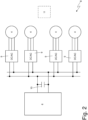
- the road vehicle 1 is provided with an electric power system 11, which comprises the battery 6 and four electronic DC-AC power converters (inverters) 9, each controlling a respective electric machine 4; namely, each electronic power converter 9 has a DC side which is connected to the battery 6 and comprises a three-phase AC side which is connected to the respective electric machine 4.
- an electric power system 11 which comprises the battery 6 and four electronic DC-AC power converters (inverters) 9, each controlling a respective electric machine 4; namely, each electronic power converter 9 has a DC side which is connected to the battery 6 and comprises a three-phase AC side which is connected to the respective electric machine 4.
- a filter capacitor 10 is interposed which has the function of filtering the high-frequency voltage ripples determined by the operation of the electronic power converters 9.
- a control unit 11 controls the operation of each electronic power converter 9 for following a rotation speed target (positive for the forward movement and negative for the backward movement) of the respective electric machine 8 and a torque target (positive in the case of operation as motor, negative in the case of operation as generator) delivered or absorbed by the electric machine 8.
- each electronic power converter 9 applies a three-phase alternated voltage to the terminals of the electric machine 8 (and thus delivers/absorbs a three-phase alternating current which flows through the terminals of the electric machine 8).
- the control unit 11 translates the " mechanical " targets (rotation speed and delivered/absorbed torque of the electric machine 8) into “ electric " targets (among which an electric power which has to be provided to/absorbed by the electric machine 8).
- the control unit 11 identifies only one of the electronic power converters (inverters) 9 as master (namely, as guide) and identifies all the other electronic power converters (inverters) 9 as slave (namely, as followers of the master electronic power converter 9).
- Figure 3 illustrates a control logic implemented in the control unit 11 (for simplicity, the behaviour of only one slave electronic power converter 9 is shown) which shows based on time t the sequence of the activations of the three phases for each switching cycle. According to what is illustrated in Figure 3 , the control unit 11 controls the master electronic power converter 9 with a master switching period T master and controls each slave electronic power converter 9 with a respective slave switching period T slave (potentially different for each slave electronic power converter 9).
- the control unit 11 determines the master switching period T master solely based on a rotation speed of the corresponding electric machine 4; namely, the master switching period T master is established only based on the control needs of the corresponding electric machine 4 so as to perform the best control possible of the corresponding electric machine 4.
- the control unit 11 establishes a desired time difference ⁇ t* between a switching of the master electronic power converter 9 and a switching of each slave electronic power converter 9; in particular, the desired time difference ⁇ t* is potentially different for each slave electronic power converter 9, namely the three desired time differences ⁇ t* are not (always) the same with respect to one another.
- the desired time difference ⁇ t* is determined based on the master switching period T master (namely, the desired time difference ⁇ t* varies upon the varying of the master switching period T master ).
- the sole desired time difference ⁇ t* is approximately one quarter of the master switching period T master .
- the three desired time differences ⁇ t* are different from one another and could, for example be equal, to one quarter, half and three quarters of the master switching period T master .
- control unit 11 determines an actual time difference ⁇ t between the switching of the master electronic power converter 9 and the switching of each slave electronic power converter 9 (obviously the actual time difference ⁇ t is potentially different for each slave electronic power converter 9) and thus compares each desired time difference ⁇ t* with the respective actual time difference ⁇ t.
- control unit 11 changes, if necessary, the sole slave switching period T slave based on the comparison between the respective desired time difference ⁇ t* with the respective actual time difference ⁇ t; namely, the master switching period T master is always constant and solely established based on the rotation speed of the respective electric machine 4 and a (possible) difference between a desired time difference ⁇ t* and the respective actual time difference ⁇ t determines (if necessary) only a variation of the corresponding slave switching period T slave .
- the corresponding slave switching period T slave is set to be identical to the master switching period T master (namely, it is not necessary to insert a further switching between the master electronic power converter 9 and the corresponding slave electronic power converter 9).
- the corresponding slave switching period T slave is set to be different from the master switching period T master (namely, it is necessary to insert a further switching between the master electronic power converter 9 and the corresponding slave electronic power converter 9 for eliminating the difference between the desired time difference ⁇ t* and the respective actual time difference ⁇ t).
- the corresponding slave switching period T slave is set to be greater than the master switching period T master and, if a desired time difference ⁇ t* is (substantially) smaller than the respective actual time difference ⁇ t, the corresponding slave switching period T slave is set to be smaller than the master switching period T master .
- the respective slave switching period T slave is set to be smaller than the master switching period T master and preferably equal to a minimum value TS MIN (obviously smaller than the master switching period T master ), if the difference ⁇ between the desired time difference ⁇ t* and the respective actual time difference ⁇ t is greater than an upper threshold ⁇ t LOW (having a positive value), the respective slave switching period T slave is set to be greater than the master switching period T master and preferably equal to a maximum value TS MAX (obviously greater than the master switching period T master ), and if the difference ⁇ between the desired time difference ⁇ t* and the respective actual time difference ⁇ t is comprised between the lower threshold ⁇ t UP (having a negative value) and the upper threshold ⁇ t LOW (having a positive value), the respective slave switching period T slave is set to be the same as the master switching period T master .
- the control unit 11 determines the lower threshold ⁇ t UP (having a negative value) and the upper threshold ⁇ t LOW (having a positive value) based on the master switching period T master ; namely, upon the varying of the master switching period T master , also the lower threshold ⁇ t UP and the upper threshold ⁇ t LOW are varied.
- the control unit 11 determines the minimum value TS MIN and the maximum value TS MAX based on the master switching period T master ; namely, upon the varying of the master switching period T master , also the minimum value TS MIN and the maximum value TS MAX are varied.
- the control unit 11 determines the minimum value TS MIN and the maximum value TS MAX assuming that a switching frequency difference ⁇ F is (by adding or subtracting) applied to the master switching period T master ; the switching frequency difference ⁇ F has to be sufficiently high for quite quickly allowing correcting the corresponding difference ⁇ between the desired time difference ⁇ t* and the respective actual time difference ⁇ t, but it must not be too large for avoiding an excessive difference between the master switching period T master and a slave switching period T slave (namely, for avoiding penalizing the quality of the control of the respective slave electronic power converter 9).
- the switching frequency difference ⁇ F which is added to/subtracted from the master switching period T master for determining the minimum value TS MIN and the maximum value TS MAX can be constant and predetermined or can also be variable (for example, based on the master switching period T master , namely the switching frequency difference ⁇ F increases upon the decrease in the master switching period T master ).
- the minimum value TS MIN and the maximum value TS MAX differ from the master switching period T master by 0.1-10%.
- the minimum value TS MIN is clearly lower than the maximum value TS MAX and thus when a slave switching period T slave is set to be equal to the minimum value TS MIN , the respective slave electronic power converter 9 accelerates with respect to (goes faster than) the master electronic power converter 9, whereas when a slave switching period T slave is set to be equal the maximum value TS MAX , the respective slave electronic power converter 9 slows down with respect to (goes slower than) the master electronic power converter 9.
- the difference ⁇ between the desired time difference ⁇ t* and the respective actual time difference ⁇ t is comprised between the lower threshold ⁇ t UP (having a negative value) and the upper threshold ⁇ t LOW (having a positive value)
- control unit 11 generates a synchronization signal SYNCH (illustrated in Figure 3 ) exactly synchronized with the switching of the master electronic power converter 9; namely, the synchronization signal SYNCH indicates the operation of the master electronic power converter 9. Therefore, the control unit 11 determines the actual time difference ⁇ t of each slave electronic power converter 9 using the synchronization signal SYNCH as reference.
- control unit 11 carries out the comparison between each desired time difference ⁇ t* and the respective actual time difference ⁇ t and the consequent change, if needed, of the respective slave switching period T slave with every switching cycle of the electronic power converters 9.
- each slave switching period T slave could be adapted for eliminating a possible difference between the respective desired time difference ⁇ t* and the respective actual time difference ⁇ t.
- control unit 11 temporarily interrupts the change of the slave switching periods T slave based on the comparison between the desired time differences ⁇ t* and the respective actual time differences ⁇ t, when an absolute value of a difference between the rotation speeds of the electric machines 4 exceeds a synchronization threshold.
- each slave switching period T slave when all the electric machines 4 approximately have the same speed (namely, when the vehicle 1 is travelling along a straight road), it is possible to set each slave switching period T slave to be the same as the master switching period T master or anyway not much different from the master switching period T master and instead, when the electric machines 4 have different speeds (namely, when the vehicle 1 is travelling along a curve and thus the wheels 2 outside the curve have to rotate faster than the wheels 2 inside the curve) it can be more convenient not to link the slave switching periods T slave to the master switching period T master so as to be free to choose the slave switching periods T slave more suitable to the actual rotation speeds of the respective electric machines 4.
- inverters 9 In the embodiment illustrated in the accompanying figures, four electronic power converters (inverters) 9 are present and thus one master electronic power converter 9 and three slave electronic power converters 9; according to other embodiments not illustrated, a different number of electronic power converters (inverters) 9 is provided, for example two or three electronic power converters (inverters) 9 and thus one master electronic power converter 9 and one or two slave electronic power converters 9.
- the above-described control method allows minimizing the ripple of the voltage on the DC side since the voltage ripples generated by the various electronic power converters (inverters) 9 tend to compensate (reduce) one another rather than summing up.
- the above-described control method allows obtaining a destructive interference, rather than a constructive interference, between the voltage ripples generated by the various electronic power converters (inverters) 9 and thus allows reducing in a substantial manner the ripple of the voltage on the DC side.
- the capacity of the filter capacitor 10 it is possible to reduce the capacity of the filter capacitor 10: some simulations have demonstrated that, thanks to the above-described control method, the capacity of the filter capacitor 10 can be reduced by 40-50%. In this manner, the filter capacitor 10 is smaller (less bulky), lighter and less expensive.
- control method is easy and cost-effective to implement, since it does not require a high calculation power, does not require a relevant memory occupation, and especially does not require the installation of any additional physical component (hardware) with respect to what normally provided (and thus the above-described control method can also be installed in an existing road vehicle 1 with a simple software updating).
Landscapes
- Engineering & Computer Science (AREA)
- Power Engineering (AREA)
- Transportation (AREA)
- Mechanical Engineering (AREA)
- Life Sciences & Earth Sciences (AREA)
- Sustainable Development (AREA)
- Sustainable Energy (AREA)
- Electric Propulsion And Braking For Vehicles (AREA)
Abstract
Description
- This patent application claims priority from
Italian patent application no. 102023000023958 filed on November 13, 2023 - The present invention relates to a method to control an electric power system of an electric vehicle.
- An electric vehicle comprises at least one electric machine which is electrically connected to a battery and is mechanically connected to the drive wheels. In particular, the electric power system of an electric vehicle comprises at least one electronic bidirectional DC-AC power converter (namely, an inverter) which on the DC side is connected to the battery and on the AC side is connected to the electric machine and has the function of controlling the electric machine.
- During the operation of the electronic power converter, on the DC side an evident ripple of the voltage is manifested at the switching frequency of the electronic power converter (directly dependent on the rotation speed of the electric machine); this ripple of the voltage on the DC side subjects the electrochemical cells of the battery to a significant stress and must thus be filtered by installing on the DC side a filter capacitor having a suitable (i.e. sufficiently high) capacity.
- If the vehicle comprises more electric machines (for example two electric machines connected to the two front and rear axles, or four electric machines connected to the four wheels), just as many electronic bidirectional DC-AC power converters (inverters) are obviously provided, all connected to the same battery; in this situation, the ripples of the voltage on the DC side determined by all the electronic power converters can also be summed (at least for several instants) and thus it is necessary to dimension the filter capacitor in order to be able to compensate the sum of all the ripples of the voltage caused by all the electronic power converters.
-
Patent application US2012235617A1 describes a system for controlling rotary electric machines to reduce the current ripple on a DC bus. -
Patent application US2004160201A1 describes a multiple inverter system with low power bus ripples. -
Patent US7425806B2 describes a system for controlling a variable speed drive. - The object of the present invention is to provide a method for controlling an electric power system of an electric vehicle, said control method allowing reducing the weight, the bulk and the cost of the filter capacitor and being simultaneously easy and cost-effective to implement.
- According to the present invention, a method for controlling an electric power system of an electric vehicle is provided according to what is claimed in the appended claims.
- The claims describe preferred embodiments of the present invention forming integral part of the present description.
- The present invention will now be described with reference to the accompanying drawings, which illustrate a non-limiting example embodiment thereof, wherein:
-
Figure 1 is a schematic plan view of an electric road vehicle; -
Figure 2 is a schematic view of an electric power system of the road vehicle ofFigure 1 ; -
Figure 3 is a schematic view of a control mode performed by a control unit of the electric power system ofFigure 2 ; and -
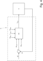
Figure 4 is a block diagram which illustrates a control logic implemented in the control unit of the electric power system ofFigure 2 . - In
Figure 1 ,reference numeral 1 indicates, as a whole, an electric vehicle provided with two drive wheels 2 (twofront drive wheels 2 and two rear drive wheels 2). - The
vehicle 1 comprises anelectric propulsion system 3 which is arranged in a front position (namely, is connected to the two front drive wheels 2), and anelectric propulsion system 3 which is arranged in a rear position (namely, is connected to the two rear drive wheels 2), is structurally totally identical to theelectric propulsion system 3 arranged in the front position, and is mechanically totally independent of and separated from theelectric propulsion system 3 arranged in the front position. - According to a different embodiment not illustrated, the
vehicle 1 comprises one single electric propulsion system 3 (arranged in a front position or arranged in a rear position) and thus has only twodrive wheels 2; in this embodiment, thevehicle 1 could alternatively also comprise a thermal propulsion system connected to thedrive wheels 2 which do not receive the motion from the singleelectric propulsion system 3. - In the embodiment illustrated in
Figure 1 , eachelectric propulsion system 3 comprises a pair of reversible (i.e. that can operate both as electric motor absorbing electric energy and generating a mechanical torque, and as electric generator absorbing mechanical energy and generating electric energy)electric machines 4 provided with respective shafts and a pair oftransmissions 5 which connect the electric machines 4 (namely, the shafts of the electric machines 4) to thecorresponding drive wheels 2 without the interposition of any friction. - The
vehicle 1 comprises abattery 6 provided with acontainer 7 and with a plurality of electrochemical cells which are arranged inside thecontainer 7 and are adapted to convert the accumulated chemical energy into electric energy and vice versa. - According to what is illustrated in
Figure 2 , theroad vehicle 1 is provided with anelectric power system 11, which comprises thebattery 6 and four electronic DC-AC power converters (inverters) 9, each controlling a respectiveelectric machine 4; namely, eachelectronic power converter 9 has a DC side which is connected to thebattery 6 and comprises a three-phase AC side which is connected to the respectiveelectric machine 4. - Between the
electronic power converters 9 and thebattery 6, afilter capacitor 10 is interposed which has the function of filtering the high-frequency voltage ripples determined by the operation of theelectronic power converters 9. - A
control unit 11 is provided which controls the operation of eachelectronic power converter 9 for following a rotation speed target (positive for the forward movement and negative for the backward movement) of the respectiveelectric machine 8 and a torque target (positive in the case of operation as motor, negative in the case of operation as generator) delivered or absorbed by theelectric machine 8. - In use, each
electronic power converter 9 applies a three-phase alternated voltage to the terminals of the electric machine 8 (and thus delivers/absorbs a three-phase alternating current which flows through the terminals of the electric machine 8). In particular, thecontrol unit 11 translates the "mechanical" targets (rotation speed and delivered/absorbed torque of the electric machine 8) into "electric" targets (among which an electric power which has to be provided to/absorbed by the electric machine 8). - The
control unit 11 identifies only one of the electronic power converters (inverters) 9 as master (namely, as guide) and identifies all the other electronic power converters (inverters) 9 as slave (namely, as followers of the master electronic power converter 9).Figure 3 illustrates a control logic implemented in the control unit 11 (for simplicity, the behaviour of only one slaveelectronic power converter 9 is shown) which shows based on time t the sequence of the activations of the three phases for each switching cycle. According to what is illustrated inFigure 3 , thecontrol unit 11 controls the masterelectronic power converter 9 with a master switching period Tmaster and controls each slaveelectronic power converter 9 with a respective slave switching period Tslave (potentially different for each slave electronic power converter 9). - The
control unit 11 determines the master switching period Tmaster solely based on a rotation speed of the correspondingelectric machine 4; namely, the master switching period Tmaster is established only based on the control needs of the correspondingelectric machine 4 so as to perform the best control possible of the correspondingelectric machine 4. - In use and according to what is illustrated in
Figure 4 , thecontrol unit 11 establishes a desired time difference Δt* between a switching of the masterelectronic power converter 9 and a switching of each slaveelectronic power converter 9; in particular, the desired time difference Δt* is potentially different for each slaveelectronic power converter 9, namely the three desired time differences Δt* are not (always) the same with respect to one another. In particular, the desired time difference Δt* is determined based on the master switching period Tmaster (namely, the desired time difference Δt* varies upon the varying of the master switching period Tmaster). - In the embodiment where only two
electronic power converters 9 are present (one masterelectronic power converter 9 and one slave electronic power converter 9), the sole desired time difference Δt* is approximately one quarter of the master switching period Tmaster. In the embodiment where fourelectronic power converters 9 are present (one masterelectronic power converter 9 and three slave electronic power converters 9), the three desired time differences Δt* are different from one another and could, for example be equal, to one quarter, half and three quarters of the master switching period Tmaster. - In use and according to what is illustrated in
Figure 4 , thecontrol unit 11 determines an actual time difference Δt between the switching of the masterelectronic power converter 9 and the switching of each slave electronic power converter 9 (obviously the actual time difference Δt is potentially different for each slave electronic power converter 9) and thus compares each desired time difference Δt* with the respective actual time difference Δt. Furthermore, thecontrol unit 11 changes, if necessary, the sole slave switching period Tslave based on the comparison between the respective desired time difference Δt* with the respective actual time difference Δt; namely, the master switching period Tmaster is always constant and solely established based on the rotation speed of the respectiveelectric machine 4 and a (possible) difference between a desired time difference Δt* and the respective actual time difference Δt determines (if necessary) only a variation of the corresponding slave switching period Tslave. - If a desired time difference Δt* is the same as the respective actual time difference Δt, the corresponding slave switching period Tslave is set to be identical to the master switching period Tmaster (namely, it is not necessary to insert a further switching between the master
electronic power converter 9 and the corresponding slave electronic power converter 9). - If a desired time difference Δt* is (substantially) different from the respective actual time difference Δt, the corresponding slave switching period Tslave is set to be different from the master switching period Tmaster (namely, it is necessary to insert a further switching between the master
electronic power converter 9 and the corresponding slaveelectronic power converter 9 for eliminating the difference between the desired time difference Δt* and the respective actual time difference Δt). - According to a preferred embodiment, if a desired time difference Δt* is (substantially) greater than the respective actual time difference Δt, the corresponding slave switching period Tslave is set to be greater than the master switching period Tmaster and, if a desired time difference Δt* is (substantially) smaller than the respective actual time difference Δt, the corresponding slave switching period Tslave is set to be smaller than the master switching period Tmaster.
- According to a preferred embodiment, a difference ε is calculated between a desired time difference Δt* and the respective actual time difference Δt (ε = Δt* - Δt): if the difference ε between the desired time difference Δt* and the respective actual time difference Δt is smaller than a lower threshold ΔtUP (having a negative value, i.e. lower than zero), the respective slave switching period Tslave is set to be smaller than the master switching period Tmaster and preferably equal to a minimum value TSMIN (obviously smaller than the master switching period Tmaster), if the difference ε between the desired time difference Δt* and the respective actual time difference Δt is greater than an upper threshold ΔtLOW (having a positive value), the respective slave switching period Tslave is set to be greater than the master switching period Tmaster and preferably equal to a maximum value TSMAX (obviously greater than the master switching period Tmaster), and if the difference ε between the desired time difference Δt* and the respective actual time difference Δt is comprised between the lower threshold ΔtUP (having a negative value) and the upper threshold ΔtLOW (having a positive value), the respective slave switching period Tslave is set to be the same as the master switching period Tmaster.
- According to a preferred embodiment, the
control unit 11 determines the lower threshold ΔtUP (having a negative value) and the upper threshold ΔtLOW (having a positive value) based on the master switching period Tmaster; namely, upon the varying of the master switching period Tmaster, also the lower threshold ΔtUP and the upper threshold ΔtLOW are varied. Similarly, according to a preferred embodiment, thecontrol unit 11 determines the minimum value TSMIN and the maximum value TSMAX based on the master switching period Tmaster; namely, upon the varying of the master switching period Tmaster, also the minimum value TSMIN and the maximum value TSMAX are varied. - Preferably, the
control unit 11 determines the minimum value TSMIN and the maximum value TSMAX assuming that a switching frequency difference ΔF is (by adding or subtracting) applied to the master switching period Tmaster; the switching frequency difference ΔF has to be sufficiently high for quite quickly allowing correcting the corresponding difference ε between the desired time difference Δt* and the respective actual time difference Δt, but it must not be too large for avoiding an excessive difference between the master switching period Tmaster and a slave switching period Tslave (namely, for avoiding penalizing the quality of the control of the respective slave electronic power converter 9). The switching frequency difference ΔF which is added to/subtracted from the master switching period Tmaster for determining the minimum value TSMIN and the maximum value TSMAX can be constant and predetermined or can also be variable (for example, based on the master switching period Tmaster, namely the switching frequency difference ΔF increases upon the decrease in the master switching period Tmaster). - Namely, the minimum value TSMIN and the maximum value TSMAX are calculated using the following equations:


- By way of example, generally the minimum value TSMIN and the maximum value TSMAX differ from the master switching period Tmaster by 0.1-10%.
- The minimum value TSMIN is clearly lower than the maximum value TSMAX and thus when a slave switching period Tslave is set to be equal to the minimum value TSMIN, the respective slave
electronic power converter 9 accelerates with respect to (goes faster than) the masterelectronic power converter 9, whereas when a slave switching period Tslave is set to be equal the maximum value TSMAX, the respective slaveelectronic power converter 9 slows down with respect to (goes slower than) the masterelectronic power converter 9. - Summarizing, if the difference ε between the desired time difference Δt* and the respective actual time difference Δt is smaller than the lower threshold ΔtUP (having a negative value), it means that the actual time difference Δt is higher than the desired time difference Δt* (ε = Δt* - Δt) and thus it is necessary to accelerate the respective slave
electronic power converter 9 setting the respective slave switching period Tslave to be smaller than the master switching period Tmaster and equal to the minimum value TSMIN; whereas, if the difference ε between the desired time difference Δt* and the respective actual time difference Δt is greater than the upper threshold ΔtLOW (having a positive value), it means that the actual time difference Δt is lower than the desired time difference Δt* (ε = Δt* - Δt) and it is thus necessary to slow down the respective slaveelectronic power converter 9 setting the respective slave switching period Tslave to be greater than the master switching period Tmaster and equal to the maximum value TSMAX. Finally, if the difference ε between the desired time difference Δt* and the respective actual time difference Δt is comprised between the lower threshold ΔtUP (having a negative value) and the upper threshold ΔtLOW (having a positive value), it means that the actual time difference Δt is quite (sufficiently) similar to the desired time difference Δt* (ε = Δt* - Δt) and thus the respective slaveelectronic power converter 9 can have the same speed of the respective masterelectronic power converter 9 setting the respective slave switching period Tslave to be identical to the master switching period Tmaster. - According to a preferred embodiment, the
control unit 11 generates a synchronization signal SYNCH (illustrated inFigure 3 ) exactly synchronized with the switching of the masterelectronic power converter 9; namely, the synchronization signal SYNCH indicates the operation of the masterelectronic power converter 9. Therefore, thecontrol unit 11 determines the actual time difference Δt of each slaveelectronic power converter 9 using the synchronization signal SYNCH as reference. - According to a preferred embodiment, the
control unit 11 carries out the comparison between each desired time difference Δt* and the respective actual time difference Δt and the consequent change, if needed, of the respective slave switching period Tslave with every switching cycle of theelectronic power converters 9. Namely, potentially with every switching cycle of theelectronic power converters 9, each slave switching period Tslave could be adapted for eliminating a possible difference between the respective desired time difference Δt* and the respective actual time difference Δt. - According to a preferred embodiment, the
control unit 11 temporarily interrupts the change of the slave switching periods Tslave based on the comparison between the desired time differences Δt* and the respective actual time differences Δt, when an absolute value of a difference between the rotation speeds of theelectric machines 4 exceeds a synchronization threshold. In other words, in order to carry out a good control of anelectric machine 4, it is necessary for the switching period to be suitable to the rotation speed of the electric machine 4: when all theelectric machines 4 approximately have the same speed (namely, when thevehicle 1 is travelling along a straight road), it is possible to set each slave switching period Tslave to be the same as the master switching period Tmaster or anyway not much different from the master switching period Tmaster and instead, when theelectric machines 4 have different speeds (namely, when thevehicle 1 is travelling along a curve and thus thewheels 2 outside the curve have to rotate faster than thewheels 2 inside the curve) it can be more convenient not to link the slave switching periods Tslave to the master switching period Tmaster so as to be free to choose the slave switching periods Tslave more suitable to the actual rotation speeds of the respectiveelectric machines 4. It is important to observe that during the travelling of a curve, theelectric machines 4 are hardly called to generate or absorb high torques and mechanical powers (namely, close to the maximum values) and thus the fact of compensating in a less effective manner the voltage ripple on the DC side is less penalizing (stressful) for thebattery 6. - In the embodiment illustrated in the accompanying figures, four electronic power converters (inverters) 9 are present and thus one master
electronic power converter 9 and three slaveelectronic power converters 9; according to other embodiments not illustrated, a different number of electronic power converters (inverters) 9 is provided, for example two or three electronic power converters (inverters) 9 and thus one masterelectronic power converter 9 and one or two slaveelectronic power converters 9. - The embodiments described herein can be combined with one another without departing from the scope of protection of the present invention.
- The above-described control method has numerous advantages.
- Firstly, the above-described control method allows minimizing the ripple of the voltage on the DC side since the voltage ripples generated by the various electronic power converters (inverters) 9 tend to compensate (reduce) one another rather than summing up. In other words, the above-described control method allows obtaining a destructive interference, rather than a constructive interference, between the voltage ripples generated by the various electronic power converters (inverters) 9 and thus allows reducing in a substantial manner the ripple of the voltage on the DC side.
- Therefore, thanks to the above-described control method, it is possible to reduce the capacity of the filter capacitor 10: some simulations have demonstrated that, thanks to the above-described control method, the capacity of the
filter capacitor 10 can be reduced by 40-50%. In this manner, thefilter capacitor 10 is smaller (less bulky), lighter and less expensive. - Furthermore, the above-described control method is easy and cost-effective to implement, since it does not require a high calculation power, does not require a relevant memory occupation, and especially does not require the installation of any additional physical component (hardware) with respect to what normally provided (and thus the above-described control method can also be installed in an existing
road vehicle 1 with a simple software updating). -
- 1
- vehicle
- 2
- wheels
- 3
- propulsion system
- 4
- electric machine
- 5
- transmission
- 6
- battery
- 7
- container
- 8
- electric power system
- 9
- electronic power converter
- 10
- filter capacitor
- 11
- control unit
- t
- time
- Tmaster
- master switching period
- Tslave
- slave switching period
- Δt*
- desired time difference
- Δt
- actual time difference
- ΔtUP
- lower threshold
- ΔtLOW
- upper threshold
- ε
- difference
- TSMIN
- minimum value
- TSMAX
- maximum value
- SYNCH
- synchronization signal
Claims (17)
- A method to control an electric power system (18) of an electric vehicle (1) and provided with at least two electric machines (4); the electric power system (18) comprises two electronic DC-AC power converters (9), each having a DC side connected to a battery (6) and an AC side connected to a respective electric machine (4); the control method comprises the steps of:controlling a first electronic power converter (9) with a master switching period (Tmaster);controlling a second electronic power converter (9) with a slave switching period (Tslave); andestablishing a desired time difference (Δt*) between a switching of the first electronic power converter (9) and a switching of the second electronic power converter (9);the control method is characterized in that it comprises the steps of:determining an actual time difference (Δt) between the switching of the first electronic power converter (9) and the switching of the second electronic power converter (9);comparing the desired time difference (Δt*) with the actual time difference (Δt); andchanging, if necessary, the sole slave switching period (Tslave) based on the comparison between the desired time difference (Δt*) with the actual time difference (Δt).
- The control method according to claim 1, wherein, if the desired time difference (Δt*) is the same as the actual time difference (Δt), the slave switching period (Tslave) is set to be identical to the master switching period (Tmaster).
- The control method according to claim 1 or 2, wherein, if the desired time difference (Δt*) is different from the actual time difference (Δt), the slave switching period (Tslave) is set to be different from the master switching period (Tmaster).
- The control method according to claim 3, wherein, if the desired time difference (Δt*) is greater than the actual time difference (Δt), the slave switching period (Tslave) is set to be greater than the master switching period (Tmaster) and, if the desired time difference (Δt*) is smaller than the actual time difference (Δt), the slave switching period (Tslave) is set to be smaller than the master switching period (Tmaster).
- The control method according to one of the claims from 1 to 4, wherein:if a difference (ε) between the desired time difference (Δt*) and the actual time difference (Δt) is smaller than a lower threshold (ΔtUP), the slave switching period (Tslave) is set to be smaller than the master switching period (Tmaster);if the difference (ε) between the desired time difference (Δt*) and the actual time difference (Δt) is greater than an upper threshold (ΔLOW), the slave switching period (Tslave) is set to be greater than the master switching period (Tmaster); andif the difference (ε) between the desired time difference (Δt*) and the actual time difference (Δt) is comprised between the lower threshold (ΔtUP) and the upper threshold (ΔtLOW), the slave switching period (Tslave) is set to be the same as the master switching period (Tmaster).
- The control method according to claim 5, wherein the lower threshold (ΔtUP) is negative and the upper threshold (ΔtLOW) is positive.
- The control method according to claim 5 or 6 and comprising the further step of determining the lower threshold (ΔtUP) and the upper threshold (ΔtLOW) based on the master switching period (Tmaster).
- The control method according to claim 5, 6 or 7, wherein:if a difference (ε) between the desired time difference (Δt*) and the actual time difference (Δt) is smaller than the lower threshold (ΔtUP), the slave switching period (Tslave) is set to be equal to a minimum value (TSMIN) smaller than the master switching period (Tmaster); andif the difference (ε) between the desired time difference (Δt*) and the actual time difference (Δt) is greater than the upper threshold (ΔtLOW), the slave switching period (Tslave) is set to be equal to a maximum value (TSMAX) greater than the master switching period (Tmaster).
- The control method according to claim 8 and comprising the further step of determining the minimum value (TSMIN) and the maximum value (TSMAX) based on the master switching period (Tmaster).
- The control method according to claim 9, wherein the minimum value (TSMIN) and the maximum value (TSMAX) are determined assuming that a switching frequency difference (ΔF) is applied to the master switching period (Tmaster).
- The control method according to claim 10, wherein the minimum value (TSMIN) and the maximum value (TSMAX) are calculated using the following equations:

 TSMIN minimum value;TSMAX maximum value;Tmaster master switching period;ΔF switching frequency difference.
 - The control method according to one of the claims from 1 to 10 and comprising the steps of:generating a synchronization signal (SYNCH) exactly corresponding to the switching period of the first electronic power converter (9); anddetermining the actual time difference (Δt) using the synchronization signal (SYNCH) as reference.
- The control method according to one of the claims from 1 to 12 and comprising the further step of determining the desired time difference (Δt*) based on the master switching period (Tmaster).
- The control method according to claim 13, wherein the desired time difference (Δt*) approximately is one quarter of the master switching period (Tmaster).
- The control method according to one of the claims from 1 to 14, wherein the master switching period (Tmaster) is solely determined based on a rotation speed of the corresponding electric machine (4).
- The control method according to one of the claims from 1 to 15, wherein the comparison between the desired time difference (Δt*) and the actual time difference (Δt) and the consequent change, if needed, of the slave switching period (Tslave) are carried out with every switching cycle of the electronic power converters (9).
- The control method according to one of the claims from 1 to 16 and comprising the further step of temporarily interrupting the change of the slave switching period (Tslave) based on the comparison between the desired time difference (Δt*) and the actual time difference (Δt), when an absolute value of a difference between the rotation speeds of the two electric machines (4) exceeds a synchronization threshold.
Applications Claiming Priority (1)
| Application Number | Priority Date | Filing Date | Title |
|---|---|---|---|
| IT102023000023958A IT202300023958A1 (en) | 2023-11-13 | 2023-11-13 | METHOD OF CONTROL OF AN ELECTRICAL POWER SYSTEM OF AN ELECTRIC-POWER VEHICLE |
Publications (1)
| Publication Number | Publication Date |
|---|---|
| EP4552897A1 true EP4552897A1 (en) | 2025-05-14 |
Family
ID=89983516
Family Applications (1)
| Application Number | Title | Priority Date | Filing Date |
|---|---|---|---|
| EP24212443.6A Pending EP4552897A1 (en) | 2023-11-13 | 2024-11-12 | Method to control an electric power system of an electric vehicle |
Country Status (5)
| Country | Link |
|---|---|
| US (1) | US20250153574A1 (en) |
| EP (1) | EP4552897A1 (en) |
| JP (1) | JP2025080242A (en) |
| CN (1) | CN119995408A (en) |
| IT (1) | IT202300023958A1 (en) |
Citations (3)
| Publication number | Priority date | Publication date | Assignee | Title |
|---|---|---|---|---|
| US20040160201A1 (en) | 2003-02-14 | 2004-08-19 | Rahman Khwaja M. | Multiple inverter system with low power bus ripples and method therefor |
| US7425806B2 (en) | 2004-04-12 | 2008-09-16 | York International Corporation | System and method for controlling a variable speed drive |
| US20120235617A1 (en) | 2011-03-16 | 2012-09-20 | Singh Brij N | System for controlling rotary electric machines to reduce current ripple on a direct current bus |
-
2023
- 2023-11-13 IT IT102023000023958A patent/IT202300023958A1/en unknown
-
2024
- 2024-11-05 US US18/937,932 patent/US20250153574A1/en active Pending
- 2024-11-12 JP JP2024197459A patent/JP2025080242A/en active Pending
- 2024-11-12 EP EP24212443.6A patent/EP4552897A1/en active Pending
- 2024-11-12 CN CN202411608796.9A patent/CN119995408A/en active Pending
Patent Citations (3)
| Publication number | Priority date | Publication date | Assignee | Title |
|---|---|---|---|---|
| US20040160201A1 (en) | 2003-02-14 | 2004-08-19 | Rahman Khwaja M. | Multiple inverter system with low power bus ripples and method therefor |
| US7425806B2 (en) | 2004-04-12 | 2008-09-16 | York International Corporation | System and method for controlling a variable speed drive |
| US20120235617A1 (en) | 2011-03-16 | 2012-09-20 | Singh Brij N | System for controlling rotary electric machines to reduce current ripple on a direct current bus |
Also Published As
| Publication number | Publication date |
|---|---|
| IT202300023958A1 (en) | 2025-05-13 |
| JP2025080242A (en) | 2025-05-23 |
| US20250153574A1 (en) | 2025-05-15 |
| CN119995408A (en) | 2025-05-13 |
Similar Documents
| Publication | Publication Date | Title |
|---|---|---|
| US10784698B2 (en) | Modulation index improvement by intelligent battery | |
| EP2804309B1 (en) | Three-level power conversion device | |
| EP2686950B1 (en) | System for controlling rotary electric machines to reduce current ripple on direct current bus | |
| US5389749A (en) | Elevator system | |
| EP2096747B1 (en) | Motor driving apparatus | |
| KR101787823B1 (en) | Electrically-driven vehicle | |
| US5880574A (en) | Control system for electric vehicle | |
| EP0401057B1 (en) | Variable-speed driving system | |
| EP2251224A1 (en) | Electric vehicle driving device | |
| US20040160201A1 (en) | Multiple inverter system with low power bus ripples and method therefor | |
| EP2003010A2 (en) | Control apparatus for rotational electric machine and driving apparatus for vehicle | |
| US9895983B2 (en) | Propulsion system and method for driving a vehicle | |
| EP1864847A1 (en) | Hybrid vehicle | |
| KR102780380B1 (en) | Method for controlling an electric machine | |
| KR101850415B1 (en) | Power supply system | |
| WO2011021443A1 (en) | Electric-vehicle propulsion power-conversion device | |
| US20150311851A1 (en) | Switching control device | |
| US20200162005A1 (en) | Partial-load phase deactivation of polyphase electric machine | |
| EP3484043A1 (en) | Motor controller, power converter, auxiliary power source, and method for controlling auxiliary power source | |
| KR102649967B1 (en) | Method and system for configuring an ac battery for ac charging | |
| JP7600837B2 (en) | Power Conversion Equipment | |
| US20250153574A1 (en) | Method to control an electric power system of an electric vehicle | |
| JP7785101B2 (en) | Battery packs and automobiles | |
| JP2017143654A (en) | Electric car | |
| JP7802929B2 (en) | How to Control a Power Converter with Variable Switching Frequency |
Legal Events
| Date | Code | Title | Description |
|---|---|---|---|
| PUAI | Public reference made under article 153(3) epc to a published international application that has entered the european phase |
Free format text: ORIGINAL CODE: 0009012 |
|
| STAA | Information on the status of an ep patent application or granted ep patent |
Free format text: STATUS: THE APPLICATION HAS BEEN PUBLISHED |
|
| AK | Designated contracting states |
Kind code of ref document: A1 Designated state(s): AL AT BE BG CH CY CZ DE DK EE ES FI FR GB GR HR HU IE IS IT LI LT LU LV MC ME MK MT NL NO PL PT RO RS SE SI SK SM TR |
|
| STAA | Information on the status of an ep patent application or granted ep patent |
Free format text: STATUS: REQUEST FOR EXAMINATION WAS MADE |
|
| 17P | Request for examination filed |
Effective date: 20251113 |
|
| GRAP | Despatch of communication of intention to grant a patent |
Free format text: ORIGINAL CODE: EPIDOSNIGR1 |
|
| STAA | Information on the status of an ep patent application or granted ep patent |
Free format text: STATUS: GRANT OF PATENT IS INTENDED |