EP4552882A1 - Battery frame, power battery, and vehicle - Google Patents
Battery frame, power battery, and vehicle Download PDFInfo
- Publication number
- EP4552882A1 EP4552882A1 EP23876226.4A EP23876226A EP4552882A1 EP 4552882 A1 EP4552882 A1 EP 4552882A1 EP 23876226 A EP23876226 A EP 23876226A EP 4552882 A1 EP4552882 A1 EP 4552882A1
- Authority
- EP
- European Patent Office
- Prior art keywords
- side beam
- cavity
- battery
- battery frame
- vehicle
- Prior art date
- Legal status (The legal status is an assumption and is not a legal conclusion. Google has not performed a legal analysis and makes no representation as to the accuracy of the status listed.)
- Pending
Links
Images


Classifications
-
- B—PERFORMING OPERATIONS; TRANSPORTING
- B60—VEHICLES IN GENERAL
- B60K—ARRANGEMENT OR MOUNTING OF PROPULSION UNITS OR OF TRANSMISSIONS IN VEHICLES; ARRANGEMENT OR MOUNTING OF PLURAL DIVERSE PRIME-MOVERS IN VEHICLES; AUXILIARY DRIVES FOR VEHICLES; INSTRUMENTATION OR DASHBOARDS FOR VEHICLES; ARRANGEMENTS IN CONNECTION WITH COOLING, AIR INTAKE, GAS EXHAUST OR FUEL SUPPLY OF PROPULSION UNITS IN VEHICLES
- B60K1/00—Arrangement or mounting of electrical propulsion units
- B60K1/04—Arrangement or mounting of electrical propulsion units of the electric storage means for propulsion
-
- B—PERFORMING OPERATIONS; TRANSPORTING
- B60—VEHICLES IN GENERAL
- B60L—PROPULSION OF ELECTRICALLY-PROPELLED VEHICLES; SUPPLYING ELECTRIC POWER FOR AUXILIARY EQUIPMENT OF ELECTRICALLY-PROPELLED VEHICLES; ELECTRODYNAMIC BRAKE SYSTEMS FOR VEHICLES IN GENERAL; MAGNETIC SUSPENSION OR LEVITATION FOR VEHICLES; MONITORING OPERATING VARIABLES OF ELECTRICALLY-PROPELLED VEHICLES; ELECTRIC SAFETY DEVICES FOR ELECTRICALLY-PROPELLED VEHICLES
- B60L50/00—Electric propulsion with power supplied within the vehicle
- B60L50/50—Electric propulsion with power supplied within the vehicle using propulsion power supplied by batteries or fuel cells
- B60L50/60—Electric propulsion with power supplied within the vehicle using propulsion power supplied by batteries or fuel cells using power supplied by batteries
- B60L50/64—Constructional details of batteries specially adapted for electric vehicles
-
- B—PERFORMING OPERATIONS; TRANSPORTING
- B60—VEHICLES IN GENERAL
- B60L—PROPULSION OF ELECTRICALLY-PROPELLED VEHICLES; SUPPLYING ELECTRIC POWER FOR AUXILIARY EQUIPMENT OF ELECTRICALLY-PROPELLED VEHICLES; ELECTRODYNAMIC BRAKE SYSTEMS FOR VEHICLES IN GENERAL; MAGNETIC SUSPENSION OR LEVITATION FOR VEHICLES; MONITORING OPERATING VARIABLES OF ELECTRICALLY-PROPELLED VEHICLES; ELECTRIC SAFETY DEVICES FOR ELECTRICALLY-PROPELLED VEHICLES
- B60L50/00—Electric propulsion with power supplied within the vehicle
- B60L50/50—Electric propulsion with power supplied within the vehicle using propulsion power supplied by batteries or fuel cells
- B60L50/60—Electric propulsion with power supplied within the vehicle using propulsion power supplied by batteries or fuel cells using power supplied by batteries
- B60L50/66—Arrangements of batteries
-
- H—ELECTRICITY
- H01—ELECTRIC ELEMENTS
- H01M—PROCESSES OR MEANS, e.g. BATTERIES, FOR THE DIRECT CONVERSION OF CHEMICAL ENERGY INTO ELECTRICAL ENERGY
- H01M10/00—Secondary cells; Manufacture thereof
- H01M10/60—Heating or cooling; Temperature control
- H01M10/62—Heating or cooling; Temperature control specially adapted for specific applications
- H01M10/625—Vehicles
-
- H—ELECTRICITY
- H01—ELECTRIC ELEMENTS
- H01M—PROCESSES OR MEANS, e.g. BATTERIES, FOR THE DIRECT CONVERSION OF CHEMICAL ENERGY INTO ELECTRICAL ENERGY
- H01M10/00—Secondary cells; Manufacture thereof
- H01M10/60—Heating or cooling; Temperature control
- H01M10/65—Means for temperature control structurally associated with the cells
- H01M10/656—Means for temperature control structurally associated with the cells characterised by the type of heat-exchange fluid
- H01M10/6567—Liquids
- H01M10/6568—Liquids characterised by flow circuits, e.g. loops, located externally to the cells or cell casings
-
- H—ELECTRICITY
- H01—ELECTRIC ELEMENTS
- H01M—PROCESSES OR MEANS, e.g. BATTERIES, FOR THE DIRECT CONVERSION OF CHEMICAL ENERGY INTO ELECTRICAL ENERGY
- H01M50/00—Constructional details or processes of manufacture of the non-active parts of electrochemical cells other than fuel cells, e.g. hybrid cells
- H01M50/20—Mountings; Secondary casings or frames; Racks, modules or packs; Suspension devices; Shock absorbers; Transport or carrying devices; Holders
- H01M50/204—Racks, modules or packs for multiple batteries or multiple cells
-
- H—ELECTRICITY
- H01—ELECTRIC ELEMENTS
- H01M—PROCESSES OR MEANS, e.g. BATTERIES, FOR THE DIRECT CONVERSION OF CHEMICAL ENERGY INTO ELECTRICAL ENERGY
- H01M50/00—Constructional details or processes of manufacture of the non-active parts of electrochemical cells other than fuel cells, e.g. hybrid cells
- H01M50/20—Mountings; Secondary casings or frames; Racks, modules or packs; Suspension devices; Shock absorbers; Transport or carrying devices; Holders
- H01M50/233—Mountings; Secondary casings or frames; Racks, modules or packs; Suspension devices; Shock absorbers; Transport or carrying devices; Holders characterised by physical properties of casings or racks, e.g. dimensions
- H01M50/242—Mountings; Secondary casings or frames; Racks, modules or packs; Suspension devices; Shock absorbers; Transport or carrying devices; Holders characterised by physical properties of casings or racks, e.g. dimensions adapted for protecting batteries against vibrations, collision impact or swelling
-
- H—ELECTRICITY
- H01—ELECTRIC ELEMENTS
- H01M—PROCESSES OR MEANS, e.g. BATTERIES, FOR THE DIRECT CONVERSION OF CHEMICAL ENERGY INTO ELECTRICAL ENERGY
- H01M50/00—Constructional details or processes of manufacture of the non-active parts of electrochemical cells other than fuel cells, e.g. hybrid cells
- H01M50/20—Mountings; Secondary casings or frames; Racks, modules or packs; Suspension devices; Shock absorbers; Transport or carrying devices; Holders
- H01M50/244—Secondary casings; Racks; Suspension devices; Carrying devices; Holders characterised by their mounting method
-
- H—ELECTRICITY
- H01—ELECTRIC ELEMENTS
- H01M—PROCESSES OR MEANS, e.g. BATTERIES, FOR THE DIRECT CONVERSION OF CHEMICAL ENERGY INTO ELECTRICAL ENERGY
- H01M50/00—Constructional details or processes of manufacture of the non-active parts of electrochemical cells other than fuel cells, e.g. hybrid cells
- H01M50/20—Mountings; Secondary casings or frames; Racks, modules or packs; Suspension devices; Shock absorbers; Transport or carrying devices; Holders
- H01M50/249—Mountings; Secondary casings or frames; Racks, modules or packs; Suspension devices; Shock absorbers; Transport or carrying devices; Holders specially adapted for aircraft or vehicles, e.g. cars or trains
-
- H—ELECTRICITY
- H01—ELECTRIC ELEMENTS
- H01M—PROCESSES OR MEANS, e.g. BATTERIES, FOR THE DIRECT CONVERSION OF CHEMICAL ENERGY INTO ELECTRICAL ENERGY
- H01M50/00—Constructional details or processes of manufacture of the non-active parts of electrochemical cells other than fuel cells, e.g. hybrid cells
- H01M50/20—Mountings; Secondary casings or frames; Racks, modules or packs; Suspension devices; Shock absorbers; Transport or carrying devices; Holders
- H01M50/262—Mountings; Secondary casings or frames; Racks, modules or packs; Suspension devices; Shock absorbers; Transport or carrying devices; Holders with fastening means, e.g. locks
-
- H—ELECTRICITY
- H01—ELECTRIC ELEMENTS
- H01M—PROCESSES OR MEANS, e.g. BATTERIES, FOR THE DIRECT CONVERSION OF CHEMICAL ENERGY INTO ELECTRICAL ENERGY
- H01M50/00—Constructional details or processes of manufacture of the non-active parts of electrochemical cells other than fuel cells, e.g. hybrid cells
- H01M50/20—Mountings; Secondary casings or frames; Racks, modules or packs; Suspension devices; Shock absorbers; Transport or carrying devices; Holders
- H01M50/289—Mountings; Secondary casings or frames; Racks, modules or packs; Suspension devices; Shock absorbers; Transport or carrying devices; Holders characterised by spacing elements or positioning means within frames, racks or packs
- H01M50/293—Mountings; Secondary casings or frames; Racks, modules or packs; Suspension devices; Shock absorbers; Transport or carrying devices; Holders characterised by spacing elements or positioning means within frames, racks or packs characterised by the material
-
- B—PERFORMING OPERATIONS; TRANSPORTING
- B60—VEHICLES IN GENERAL
- B60K—ARRANGEMENT OR MOUNTING OF PROPULSION UNITS OR OF TRANSMISSIONS IN VEHICLES; ARRANGEMENT OR MOUNTING OF PLURAL DIVERSE PRIME-MOVERS IN VEHICLES; AUXILIARY DRIVES FOR VEHICLES; INSTRUMENTATION OR DASHBOARDS FOR VEHICLES; ARRANGEMENTS IN CONNECTION WITH COOLING, AIR INTAKE, GAS EXHAUST OR FUEL SUPPLY OF PROPULSION UNITS IN VEHICLES
- B60K1/00—Arrangement or mounting of electrical propulsion units
- B60K1/04—Arrangement or mounting of electrical propulsion units of the electric storage means for propulsion
- B60K2001/0405—Arrangement or mounting of electrical propulsion units of the electric storage means for propulsion characterised by their position
- B60K2001/0438—Arrangement under the floor
-
- B—PERFORMING OPERATIONS; TRANSPORTING
- B62—LAND VEHICLES FOR TRAVELLING OTHERWISE THAN ON RAILS
- B62D—MOTOR VEHICLES; TRAILERS
- B62D25/00—Superstructure or monocoque structure sub-units; Parts or details thereof not otherwise provided for
- B62D25/02—Side panels
- B62D25/025—Side sills thereof
-
- H—ELECTRICITY
- H01—ELECTRIC ELEMENTS
- H01M—PROCESSES OR MEANS, e.g. BATTERIES, FOR THE DIRECT CONVERSION OF CHEMICAL ENERGY INTO ELECTRICAL ENERGY
- H01M10/00—Secondary cells; Manufacture thereof
- H01M10/60—Heating or cooling; Temperature control
- H01M10/61—Types of temperature control
- H01M10/613—Cooling or keeping cold
-
- H—ELECTRICITY
- H01—ELECTRIC ELEMENTS
- H01M—PROCESSES OR MEANS, e.g. BATTERIES, FOR THE DIRECT CONVERSION OF CHEMICAL ENERGY INTO ELECTRICAL ENERGY
- H01M10/00—Secondary cells; Manufacture thereof
- H01M10/60—Heating or cooling; Temperature control
- H01M10/65—Means for temperature control structurally associated with the cells
- H01M10/655—Solid structures for heat exchange or heat conduction
- H01M10/6556—Solid parts with flow channel passages or pipes for heat exchange
- H01M10/6557—Solid parts with flow channel passages or pipes for heat exchange arranged between the cells
-
- H—ELECTRICITY
- H01—ELECTRIC ELEMENTS
- H01M—PROCESSES OR MEANS, e.g. BATTERIES, FOR THE DIRECT CONVERSION OF CHEMICAL ENERGY INTO ELECTRICAL ENERGY
- H01M10/00—Secondary cells; Manufacture thereof
- H01M10/60—Heating or cooling; Temperature control
- H01M10/65—Means for temperature control structurally associated with the cells
- H01M10/656—Means for temperature control structurally associated with the cells characterised by the type of heat-exchange fluid
- H01M10/6567—Liquids
-
- H—ELECTRICITY
- H01—ELECTRIC ELEMENTS
- H01M—PROCESSES OR MEANS, e.g. BATTERIES, FOR THE DIRECT CONVERSION OF CHEMICAL ENERGY INTO ELECTRICAL ENERGY
- H01M2220/00—Batteries for particular applications
- H01M2220/20—Batteries in motive systems, e.g. vehicle, ship, plane
-
- Y—GENERAL TAGGING OF NEW TECHNOLOGICAL DEVELOPMENTS; GENERAL TAGGING OF CROSS-SECTIONAL TECHNOLOGIES SPANNING OVER SEVERAL SECTIONS OF THE IPC; TECHNICAL SUBJECTS COVERED BY FORMER USPC CROSS-REFERENCE ART COLLECTIONS [XRACs] AND DIGESTS
- Y02—TECHNOLOGIES OR APPLICATIONS FOR MITIGATION OR ADAPTATION AGAINST CLIMATE CHANGE
- Y02E—REDUCTION OF GREENHOUSE GAS [GHG] EMISSIONS, RELATED TO ENERGY GENERATION, TRANSMISSION OR DISTRIBUTION
- Y02E60/00—Enabling technologies; Technologies with a potential or indirect contribution to GHG emissions mitigation
- Y02E60/10—Energy storage using batteries
-
- Y—GENERAL TAGGING OF NEW TECHNOLOGICAL DEVELOPMENTS; GENERAL TAGGING OF CROSS-SECTIONAL TECHNOLOGIES SPANNING OVER SEVERAL SECTIONS OF THE IPC; TECHNICAL SUBJECTS COVERED BY FORMER USPC CROSS-REFERENCE ART COLLECTIONS [XRACs] AND DIGESTS
- Y02—TECHNOLOGIES OR APPLICATIONS FOR MITIGATION OR ADAPTATION AGAINST CLIMATE CHANGE
- Y02T—CLIMATE CHANGE MITIGATION TECHNOLOGIES RELATED TO TRANSPORTATION
- Y02T10/00—Road transport of goods or passengers
- Y02T10/60—Other road transportation technologies with climate change mitigation effect
- Y02T10/70—Energy storage systems for electromobility, e.g. batteries
Definitions
- the present application relates to the technical field of power batteries, and in particular to a battery frame, a power battery and a vehicle.
- the power battery of a pure electric vehicle is usually provided under the floor of the vehicle body, and between the front and rear subframes.
- the front and rear parts of the battery are protected by the subframe, so the damage to the power battery by the front and rear collisions is relatively small.
- the side is only protected by the door sill beam and the battery's own side beam, so the side collision is more likely to cause a greater impact on the battery.
- a space distance will be reserved between the battery cell and the side beam to reduce the risk of hitting the battery cell during a side collision.
- the above problems are generally solved by strengthening the door sill beam and the battery side beam.
- strengthening the structural strength of the door sill beam and the battery side beam can protect the battery cell to a certain extent, on the one hand, it increases the weight of the vehicle and the battery frame, which does not meet the requirements of lightweight design; on the other hand, the problem of hitting the battery cell during a side collision still exists and has not been well solved.
- the main purpose of the application is to provide a battery frame, aiming to increase the cell capacity of the power battery pack while ensuring the safety of the cell during a side collision.
- the present application provides a battery frame, including: a base plate and side beams.
- the side beams are provided on opposite sides of the base plate, each side beam includes a side beam part extending along a height direction of the base plate, a connecting part provided inside the side beam part and connected to the base plate, and a fixing part provided outside the side beam part and connected to a door sill beam of a vehicle.
- the side beam part includes an upper side beam and a lower side beam, the upper side beam is provided above the lower side beam, an outer side of the lower side beam is connected to the fixing part, an inner side of the lower side beam is connected to the connecting part, a first cavity is provided at the lower side beam, and a thickness of a bottom wall of the first cavity is less than a thickness of a side wall of the first cavity.
- the battery frame further includes a scratch protection plate, the bottom wall of the first cavity is provided with a mounting position, and the scratch protection plate is detachably fixed to the mounting position.
- the scratch protection plate is fixed to the mounting position by a fastener, the mounting position forms a groove along a penetration direction of the fastener, and a head of the fastener is placed in the groove.
- the connecting part is provided with a second cavity.
- a thickness of a wall of the second cavity is greater than or equal to the thickness of the side wall of the first cavity.
- a third cavity is provided on the upper side beam, and a reinforcement structure is provided in the third cavity.
- the reinforcement structure includes a plurality of reinforcement ribs distributed inside the third cavity, the plurality of reinforcement ribs are obliquely provided between two side walls of the third cavity, and the third cavity is divided into a plurality of sub-cavities.
- a thickness of a side wall of the third cavity is less than the thickness of the side wall of the first cavity.
- a connection between the fixing part and the lower side beam is inclined.
- the fixing part includes a sink formed by a bottom depression, a fastener passes through the fixing part and is fixed to the door sill beam of the vehicle, and a head of the fastener is provided in the sink.
- the side beam is formed by an integral extrusion process.
- the power battery further includes a protective layer provided between the cell module and the battery frame.
- the present application also provides a vehicle, including: a vehicle body and the power battery described in any of the above embodiments, the two fixing parts are respectively connected to a door sill beam of the vehicle body, and a cavity structure is provided in the door sill beam.
- the door sill beam is formed by an integral extrusion process.
- the battery frame includes a base plate and side beams, the side beams are provided at opposite sides of the base plate, and each side beam includes a side beam part extending along the height direction of the base plate, a connecting part provided inside the side beam part and connected to the base plate, and a fixing part provided outside the side beam part and configured to connect to a door sill beam of a vehicle.
- the side beam part includes an upper side beam and a lower side beam, the upper side beam is provided above lower side beam.
- the outer side of the lower side beam is connected to the fixing part, and the inner side of the lower side beam is connected to the connecting part.
- a first cavity is provided at lower side beam, the bottom wall of the first cavity at lower side beam is thinned, and the thickness of the bottom wall of the first cavity is less than the thickness of the side wall of the first cavity.
- the bottom wall of the first cavity at the bottom of the side beam is thinned so that the thickness of the bottom wall of the first cavity is less than the thickness of the side wall of the first cavity, and the structure of the side beam is changed.
- the side beam is bent at this thinned point, so that during the collision, the side beam will be squeezed and deformed in an oblique upward direction, avoiding direct squeezing in the direction of the battery cell when the connection position between the battery frame and the door sill beam collapses, thereby reducing the impact force.
- the battery frame is applied to an improved door sill beam of the vehicle of the present application, and the collision force can be weakened by the door sill beam, which can further ensure the safety of the battery cell during a side collision, and the protection effect is better.
- the directional indication is only configured to explain the relative positional relationship, movement, etc. of the components in a certain posture (as shown in the drawings). If the specific posture changes, the directional indication will change accordingly.
- the power battery of a pure electric vehicle is usually provided under the floor of the vehicle body, and between the front and rear subframes.
- the front and rear parts of the battery are protected by the subframe, so the damage to the power battery by the front and rear collisions is relatively small.
- the side is only protected by the door sill beam and the battery's own side beam, so the side collision is more likely to cause a greater impact on the battery.
- a space distance will be reserved between the battery cell and the side beam to reduce the risk of hitting the battery cell during a side collision.
- the above problems are generally solved by strengthening the door sill beam and the battery side beam.
- strengthening the structural strength of the door sill beam and the battery side beam can protect the battery cell to a certain extent, on the one hand, it increases the weight of the vehicle and the battery frame, which does not meet the requirements of lightweight design; on the other hand, the problem of hitting the battery cell during a side collision still exists and has not been well solved.
- the present application provides a vehicle.
- the power battery 200 of the vehicle is installed under the floor of the vehicle body.
- the power battery 200 is connected to the door sill beam 100 of the vehicle.
- the collision force first hits the door sill beam 100, and the door sill beam 100 absorbs part of the energy during the collision.
- Part of the remaining energy is transferred to other areas of the vehicle body through the horizontal seat crossbeam on the floor of the vehicle body.
- the other part of the remaining energy is mainly transferred to the frame at the bottom of the battery through the side beam 320 of the battery frame 300, and then transferred to the vehicle body structure on another side.
- the door sill beam 100 is an aluminum extruded beam, that is, the door sill beam 100 is formed by an integrated aluminum extrusion process.
- the interior of the door sill beam 100 is a cavity structure 110, similar to a plurality of space structures, for example, a space structure in a nine-square format.
- the plurality of space structures ensure the absorption of the collision force, and when the door sill beam 100 is crushed and deformed during the collision, the side collision force can be reduced.
- the present application further provides a power battery 200 including a cell module 400 and a battery frame 300 on which the cell module 400 is installed.
- the battery frame 300 includes a base plate of front and rear side beams and two side beams 320.
- the cell module 400 is provided in the battery frame 300.
- the cell module 400 includes a cell group 410 and a cooling assembly 420.
- the cooling assembly 420 includes a liquid cooling plate 421 and a water pipe 422.
- the cooling assembly 420 is provided between the cell group 410 and the battery frame 300.
- the collision requirements of the power battery 200 are as follows: the deformation of the battery frame 300 cannot touch the cell group 410, causing the cell group 410 to deform, nor can it touch the cooling assembly 420 inside the battery frame 300, and the coolant in the cooling assembly 420 cannot flow out.
- the present application further improves the battery frame 300 to increase the cell capacity of the power battery 200 while ensuring the safety during a side collision.
- the battery frame 300 includes a base plate 310 and side beams 320 provided on both sides of the base plate 310.
- Each side beam 320 includes a side beam part 330 extending along the height direction of the base plate 310, a connecting part 360 provided inside the side beam part 330 and connected to the base plate 310, and a fixing part 370 provided outside the side beam part 330 and connected to a door sill beam 100 of the vehicle.
- the side beam part 330 includes an upper side beam 340 and a lower side beam 350.
- the upper side beam 340 is provided above the lower side beam 350.
- the outer side of the lower side beam 350 is connected to the fixing part 370 and the inner side of the lower side beam 350 is connected to the connecting part 360.
- the lower side beam 350 is provided with a first cavity 351.
- the bottom wall 353 of the first cavity 351 of the lower side beam 350 is thinned so that the thickness of the bottom wall 353 of the first cavity 351 is less than the thickness of the side wall of the first cavity 351.
- the structure of the side beam 320 is changed.
- the side beam 320 When deformed by collision, the side beam 320 is bent at the thinned part, so that the side beam 320 is bent in an oblique upward direction toward the battery frame 300 during the collision, avoiding direct squeezing toward the battery cell when the connection position between the battery frame 300 and the door sill beam 100 collapses, thereby reducing the impact force.
- the door sill beams 100 of the vehicle cooperate to weaken the collision force after the improvement described above, further ensuring the safety of the battery cell during side collision.
- the technical solution of the present application adopts a base plate 310 and a side beam 320, the side beam 320 is provided at two opposite sides of the base plate 310, and the side beam 320 includes a side beam part 330 extending along the height direction of the base plate 310, a connecting part 360 provided inside the side beam part 330 and connected to the base plate 310, and a fixing part 370 provided outside the side beam part 330 and connected to the door sill beam of the vehicle 100.
- the side beam part 330 includes an upper side beam 340 and a lower side beam 350, the upper side beam 340 is provided above the lower side beam 350.
- the outer side of the lower side beam 350 is connected to the fixing part 370, and the inner side of the lower side beam 350 is connected to the connecting part 360.
- the lower side beam 350 is provided with a first cavity 351, and a bottom wall 353 of the first cavity 351 of the lower side beam 350 is thinned, and the thickness of the bottom wall 353 of the first cavity 351 is less than the thickness of the side wall of the first cavity 351.
- the bottom wall 353 of the first cavity 351 of the lower side beam 350 is thinned so that the thickness of the bottom wall 353 of the first cavity 351 is less than the thickness of the side wall of the first cavity 351, and the structure of the side beam 320 is changed.
- the side beam 320 When deformed by collision, the side beam 320 is bent at the thinned part, so that the side beam 320 is bent in an oblique upward direction toward the battery frame 300 during the collision, avoiding direct squeezing toward the battery cell when the connection position between the battery frame 300 and the door sill beam 100 collapses, thereby reducing the impact force.
- the door sill beams 100 of the vehicle cooperate to weaken the collision force after the improvement described above, further ensuring the safety of the battery cell during side collision.
- the side beam 320 is deformed at the thinned part at the bottom of the side beam 320.
- the bottom of the side beam 320 begins to deform, so that the side beam 320 moves in an oblique upward direction, reducing the impact force on the battery cell.
- the capacity of the cell group 410 in the battery frame 300 can be increased by expanding the battery cell boundary.
- the connecting part 360 is provided with a second cavity 361.
- the thickness of the wall of the second cavity 361 is greater than or equal to the thickness of the side wall of the first cavity 351.
- the second cavity 361 is provided in the connecting part 360 to strengthen the connection between the side beam 320 of the battery and the base plate 310.
- the base plate 310 is fixed to the connecting part 360 by welding.
- the thickness of the wall of the transverse structure of the second cavity 361 is greater than the thickness of the bottom wall 353 of the first cavity 351, ensuring that the side beam 320 is not easily deformed at this point.
- the collision force can be diffused to the frame of the base plate 310 of the battery frame 300 through the second cavity 361, thereby dispersing the collision force.
- the power battery 200 in order to increase the capacity of the cell of the power battery 200 and ensuring safety during a side collision, also includes a buffer material, and a protective layer 500 made of the buffer material is provided between the battery frame 300 and the cell.
- the protective layer 500 is configured as a polyurethane filling layer.
- a liquid cooling plate 421 and a water pipe 422 for cooling are provided between the battery frame 300 and the cell group 410.
- the polyurethane filling layer wraps the liquid cooling plate 421 and the water pipe 422.
- a liquid cooling plate 421 is added between rows of cells to increase the cooling area of the cells.
- the interface between the liquid cooling plate 421 and the water pipe 422 is provided between the side beam 320 and the cell.
- polyurethane material is added.
- the polyurethane material is attached to the battery cell on one side and to the side beam on another side, and the middle is hollowed out to avoid the liquid cooling plate 421.
- the side beam 320 is deformed at the thinned part of the first cavity 351 of the lower side beam 350, so that the force area squeezed on the polyurethane material will also increase, minimizing the impact on the battery cell.
- the polyurethane material protects the liquid cooling plate 421.
- the polyurethane material can withstand an impact greater than 80Mpa, which can prevent the coolant of the liquid cooling plate 421 from flowing out when the power battery 200 is hit from the side.
- the battery frame 300 also includes a scratch protection plate 600, and the lower side beam 350 is provided with a mounting position 352, and the scratch protection plate 600 is detachably fixed to the mounting position 352.
- the scratch protection plate 600 is fixed to the mounting position 352 with bolts, and can be directly replaced after the battery is scratched.
- other detachable connection methods can also be used, such as projection welding nuts, clamping, etc.
- the scratch protection plate 600 is fixed to the mounting position 352 by a fastener 800, and the mounting position 352 forms a groove along the penetration direction of the fastener, and the head of the fastener 800 is placed in the groove.
- the bottom wall 353 of the first cavity 351 is provided with a mounting position 352, and the groove at the mounting position 352 is formed by the bottom wall 353 itself being recessed in the direction of the fastener 800.
- the fastener 800 is inserted through the bottom wall 353 and placed in the first cavity 351, and the head of the fastener 800 is hidden by the groove. In this way, even if the bottom wall 353 is thinned, the fastener 800 fixing the scratch protection plate 600 can be prevented from being exposed, thereby ensuring the aesthetics and high-end feel.
- the bottom wall 353 of the first cavity 351 is provided with a mounting position 352, and the groove at the mounting position 352 is formed by the right side wall of the fixing part 370, the bottom wall 353 and the left side wall of the connecting part 360.
- the design of the groove can prevent the head of the fastener 800 of the scratch protection plate 600 from being exposed, ensuring the aesthetics and high-end feel.
- the groove can also cause the side beam to deform here when a collision occurs, and in order to make deformation easier, the thickness of the bottom wall 353 at this point is also thinned compared to the surrounding side walls.
- the structure of the side beam 320 will not be directly squeezed in the direction of the battery cell during a collision.
- the side beam 320 will be squeezed and deformed obliquely upward, increasing the force area with the polyurethane material and reducing the impact on the cooling module and the battery cell.
- a third cavity 341 is provided on the upper side beam 340. Furthermore, a reinforcement structure is provided in the third cavity 341 to separate the third cavity 341 to form a plurality of sub-cavities.
- the reinforcement structure includes a plurality of reinforcing ribs 342 distributed in the third cavity 341.
- the plurality of reinforcing ribs 342 are obliquely provided and supported between the two side walls of the third cavity 341. While increasing the structural strength, the plurality of sub-cavities formed by the inclined plurality of reinforcing ribs 342 are also convenient for collision collapse, and have a certain effect on buffering and energy absorption.
- the force on the upper side beam 340 in the collision is smaller than that on the lower side beam 350. Therefore, the thickness of the wall of the third cavity 341 of the upper side beam 340 is smaller than the thickness of the side wall of the first cavity 351 of the lower side beam 350.
- the reinforcing ribs 342 of the third cavity 341 of the upper side beam 340 are also designed to be inclined. In this embodiment, two inclined reinforcing ribs 342 are provided in the third cavity 341, and the cross-section of the reinforcing ribs 342 and the side wall of the third cavity 341 is trapezoidal. In this way, while ensuring the collision effect, the thickness of the side beam 320 structure is minimized as much as possible to achieve the lightweight design requirements.
- the connection between the fixing part 370 and the lower side beam 350 is inclined to facilitate the connection between the fixing part 370 and the door sill beam 100.
- the thickness of the wall of the connection between the fixing part 370 and the lower side beam 350 is greater than the thickness of the wall at other positions, thereby enhancing the connection strength between the lower side beam 350 and the fixing part 370.
- the door sill beam 100 is connected to the fixing part 370 by a fastener 800.
- the fastener 800 is a bolt.
- the fixing part 370 is recessed in the Z direction to form a sink 371.
- the Z direction is the vertical direction of the base plate 310, that is, the Z direction of the vehicle.
- the bolt passes through from bottom to top to connect the fixing part 370 with the door sill beam 100. After fixing, the head of the bolt is provided in the sink 371 to avoid protruding from the bottom surface of the fixing part 370.
- the side beam 320 is formed by the integral extrusion process. That is, the side beam part 330, the fixing part 370 and the connecting part 360 are provided in one piece. In order to reduce weight and ensure lightweight, the side beam 320 can be formed by an integrated alloy extrusion process.
- the collision force first hits the door sill beam 100.
- the plurality of cavities of the door sill beam 100 will collapse and deform to absorb part of the energy.
- Part of the remaining energy is transferred to other areas of the vehicle body through the transverse seat crossbeam of the floor of the vehicle body.
- Another part of the remaining energy is transferred to the side beam part 330 through the fixing part 370.
- the side beam part 330 is induced to bend at the mounting position 352 of the anti-scratch guard plate 600.
- the side beam part 330 After the deformation, the side beam part 330 will be squeezed and deformed obliquely upward, increasing the force-bearing area of the side beam part 330 and the polyurethane material, reducing the impact on the cooling assembly 420 and the battery cell group 410.
- the excess energy is transferred to the base plate 310 of the battery frame 300 through the connecting part 360 of the battery frame 300, and then transferred to the side beam 320 on another side of the battery frame 300 through the base plate 310, and then transferred to the vehicle body structure.
Landscapes
- Engineering & Computer Science (AREA)
- Chemical & Material Sciences (AREA)
- Chemical Kinetics & Catalysis (AREA)
- Electrochemistry (AREA)
- General Chemical & Material Sciences (AREA)
- Mechanical Engineering (AREA)
- Transportation (AREA)
- Sustainable Energy (AREA)
- Sustainable Development (AREA)
- Power Engineering (AREA)
- Life Sciences & Earth Sciences (AREA)
- Combustion & Propulsion (AREA)
- Aviation & Aerospace Engineering (AREA)
- Manufacturing & Machinery (AREA)
- Body Structure For Vehicles (AREA)
- Battery Mounting, Suspending (AREA)
- Arrangement Or Mounting Of Propulsion Units For Vehicles (AREA)
Abstract
Disclosed are a battery frame, a power battery and a vehicle. The battery frame includes a base plate and side beams. The side beams are provided on opposite sides of the base plate, each side beam includes a side beam part, a connecting part provided inside the side beam part and connected to the base plate, and a fixing part provided outside the side beam part and configured to connect to a door sill beam of a vehicle. The side beam part includes a upper side beam and a lower side beam, the upper side beam is provided above the lower side beam, an outer side of the lower side beam is connected to the fixing part, and an inner side of the lower side beam is connected to the connecting part, and a first cavity is provided at the lower side beam. The bottom wall of the first cavity at the lower part of the side beam is thinned, and the thickness of the bottom wall of the first cavity is less than the thickness of the side wall of the first cavity.
Description
- This application claims priority to
Chinese Patent Application No. 202211258098.1, filed on October 13, 2022 - The present application relates to the technical field of power batteries, and in particular to a battery frame, a power battery and a vehicle.
- The power battery of a pure electric vehicle is usually provided under the floor of the vehicle body, and between the front and rear subframes. The front and rear parts of the battery are protected by the subframe, so the damage to the power battery by the front and rear collisions is relatively small. The side is only protected by the door sill beam and the battery's own side beam, so the side collision is more likely to cause a greater impact on the battery. In order to avoid the side beam from hitting the battery during a side collision, a space distance will be reserved between the battery cell and the side beam to reduce the risk of hitting the battery cell during a side collision.
- However, in order to alleviate the anxiety of electric vehicle owners, major car companies are now working hard to increase the battery power. Among them, expanding the battery cell boundary to increase the battery power is an effective solution, but limited by the influence of the vehicle width, expanding the battery cell boundary will further shorten the distance from the vehicle boundary to the battery cell, increasing the risk of hitting the battery cell during a side collision.
- At present, the above problems are generally solved by strengthening the door sill beam and the battery side beam. Although strengthening the structural strength of the door sill beam and the battery side beam can protect the battery cell to a certain extent, on the one hand, it increases the weight of the vehicle and the battery frame, which does not meet the requirements of lightweight design; on the other hand, the problem of hitting the battery cell during a side collision still exists and has not been well solved.
- The main purpose of the application is to provide a battery frame, aiming to increase the cell capacity of the power battery pack while ensuring the safety of the cell during a side collision.
- To achieve the above purpose, the present application provides a battery frame, including: a base plate and side beams. The side beams are provided on opposite sides of the base plate, each side beam includes a side beam part extending along a height direction of the base plate, a connecting part provided inside the side beam part and connected to the base plate, and a fixing part provided outside the side beam part and connected to a door sill beam of a vehicle. The side beam part includes an upper side beam and a lower side beam, the upper side beam is provided above the lower side beam, an outer side of the lower side beam is connected to the fixing part, an inner side of the lower side beam is connected to the connecting part, a first cavity is provided at the lower side beam, and a thickness of a bottom wall of the first cavity is less than a thickness of a side wall of the first cavity.
- In an embodiment, the battery frame further includes a scratch protection plate, the bottom wall of the first cavity is provided with a mounting position, and the scratch protection plate is detachably fixed to the mounting position.
- In an embodiment, the scratch protection plate is fixed to the mounting position by a fastener, the mounting position forms a groove along a penetration direction of the fastener, and a head of the fastener is placed in the groove.
- In an embodiment, the connecting part is provided with a second cavity.
- In an embodiment, a thickness of a wall of the second cavity is greater than or equal to the thickness of the side wall of the first cavity.
- In an embodiment, a third cavity is provided on the upper side beam, and a reinforcement structure is provided in the third cavity.
- In an embodiment, the reinforcement structure includes a plurality of reinforcement ribs distributed inside the third cavity, the plurality of reinforcement ribs are obliquely provided between two side walls of the third cavity, and the third cavity is divided into a plurality of sub-cavities.
- In an embodiment, a thickness of a side wall of the third cavity is less than the thickness of the side wall of the first cavity.
- In an embodiment, a connection between the fixing part and the lower side beam is inclined.
- In an embodiment, the fixing part includes a sink formed by a bottom depression, a fastener passes through the fixing part and is fixed to the door sill beam of the vehicle, and a head of the fastener is provided in the sink.
- In an embodiment, the side beam is formed by an integral extrusion process.
- The present application also provides a power battery, including: a cell module and the battery frame described in any of the above embodiments, the battery frame is configured to install the cell module.
- In an embodiment, the power battery further includes a protective layer provided between the cell module and the battery frame.
- The present application also provides a vehicle, including: a vehicle body and the power battery described in any of the above embodiments, the two fixing parts are respectively connected to a door sill beam of the vehicle body, and a cavity structure is provided in the door sill beam.
- In an embodiment, the door sill beam is formed by an integral extrusion process.
- In technical solutions of the present application, the battery frame includes a base plate and side beams, the side beams are provided at opposite sides of the base plate, and each side beam includes a side beam part extending along the height direction of the base plate, a connecting part provided inside the side beam part and connected to the base plate, and a fixing part provided outside the side beam part and configured to connect to a door sill beam of a vehicle. The side beam part includes an upper side beam and a lower side beam, the upper side beam is provided above lower side beam. The outer side of the lower side beam is connected to the fixing part, and the inner side of the lower side beam is connected to the connecting part. A first cavity is provided at lower side beam, the bottom wall of the first cavity at lower side beam is thinned, and the thickness of the bottom wall of the first cavity is less than the thickness of the side wall of the first cavity. The bottom wall of the first cavity at the bottom of the side beam is thinned so that the thickness of the bottom wall of the first cavity is less than the thickness of the side wall of the first cavity, and the structure of the side beam is changed. When deformed by collision, the side beam is bent at this thinned point, so that during the collision, the side beam will be squeezed and deformed in an oblique upward direction, avoiding direct squeezing in the direction of the battery cell when the connection position between the battery frame and the door sill beam collapses, thereby reducing the impact force. In particular, the battery frame is applied to an improved door sill beam of the vehicle of the present application, and the collision force can be weakened by the door sill beam, which can further ensure the safety of the battery cell during a side collision, and the protection effect is better.
- In order to more clearly illustrate the embodiments of the present application or the technical solutions in the related art, the drawings required for use in the embodiments or the description of the related art will be briefly introduced below. Obviously, the drawings described below are only some embodiments of the present application. For those skilled in the art other drawings can be obtained based on the structures shown in these drawings without creative work.
-
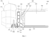
FIG. 1 is a cross-sectional schematic view of a power battery installed on a door sill beam according to an embodiment of the present application. -
FIG. 2 is a schematic view of a battery frame inFIG. 1 . -
FIG. 3 is a schematic view of a side beam inFIG. 1 . -
FIG. 4 is a schematic view of the door sill beam collapsing during a side collision inFIG. 1 . -
FIG. 5 is a schematic view of a collapse direction of the side beam inFIG. 4 . - The realization of the objective, functional characteristics, and advantages of the present application are further described with reference to the accompanying drawings.
- The technical solutions of the embodiments of the present application will be described in more detail below with reference to the accompanying drawings. It is obvious that the embodiments to be described are only some rather than all of the embodiments of the present application. All other embodiments obtained by those skilled in the art based on the embodiments of the present application without creative efforts shall fall within the scope of the present application.
- It should be noted that if there is a directional indication (such as up, down, left, right, front, rear) in the embodiments of the present application, the directional indication is only configured to explain the relative positional relationship, movement, etc. of the components in a certain posture (as shown in the drawings). If the specific posture changes, the directional indication will change accordingly.
- Besides, the descriptions associated with, e.g., "first" and "second" in the present application are merely for descriptive purposes, and cannot be understood as indicating or suggesting relative importance or impliedly indicating the number of the indicated technical feature. Therefore, the feature associated with "first" or "second" can expressly or impliedly include at least one such feature. The meaning of "and/or" appearing in the present application includes three parallel scenarios. In addition, the technical solutions between the various embodiments can be combined with each other, but they must be based on the realization of those skilled in the art. When the combination of technical solutions is contradictory or cannot be achieved, it should be considered that such a combination of technical solutions does not exist, nor is it within the scope of the present application.
- The power battery of a pure electric vehicle is usually provided under the floor of the vehicle body, and between the front and rear subframes. The front and rear parts of the battery are protected by the subframe, so the damage to the power battery by the front and rear collisions is relatively small. The side is only protected by the door sill beam and the battery's own side beam, so the side collision is more likely to cause a greater impact on the battery. In order to avoid the side beam from hitting the battery during a side collision, a space distance will be reserved between the battery cell and the side beam to reduce the risk of hitting the battery cell during a side collision.
- However, in order to alleviate the anxiety of electric vehicle owners, major car companies are now working hard to increase the battery power. Among them, expanding the battery cell boundary to increase the battery power is an effective solution, but limited by the influence of the vehicle width, expanding the battery cell boundary will further shorten the distance from the vehicle boundary to the battery cell, increasing the risk of hitting the battery cell during a side collision.
- At present, the above problems are generally solved by strengthening the door sill beam and the battery side beam. Although strengthening the structural strength of the door sill beam and the battery side beam can protect the battery cell to a certain extent, on the one hand, it increases the weight of the vehicle and the battery frame, which does not meet the requirements of lightweight design; on the other hand, the problem of hitting the battery cell during a side collision still exists and has not been well solved.
- As shown in
FIG. 1 to FIG. 3 , the present application provides a vehicle. Thepower battery 200 of the vehicle is installed under the floor of the vehicle body. Thepower battery 200 is connected to thedoor sill beam 100 of the vehicle. When the vehicle experiences a side collision, the collision force first hits thedoor sill beam 100, and thedoor sill beam 100 absorbs part of the energy during the collision. Part of the remaining energy is transferred to other areas of the vehicle body through the horizontal seat crossbeam on the floor of the vehicle body. The other part of the remaining energy is mainly transferred to the frame at the bottom of the battery through theside beam 320 of thebattery frame 300, and then transferred to the vehicle body structure on another side. - As shown in
FIG. 1 , in order to reduce the impact force during the side collision process and ensure lightweight, in an embodiment, thedoor sill beam 100 is an aluminum extruded beam, that is, thedoor sill beam 100 is formed by an integrated aluminum extrusion process. The interior of thedoor sill beam 100 is acavity structure 110, similar to a plurality of space structures, for example, a space structure in a nine-square format. The plurality of space structures ensure the absorption of the collision force, and when thedoor sill beam 100 is crushed and deformed during the collision, the side collision force can be reduced. - As shown in
FIG. 1 to FIG. 3 , the present application further provides apower battery 200 including acell module 400 and abattery frame 300 on which thecell module 400 is installed. Thebattery frame 300 includes a base plate of front and rear side beams and two side beams 320. Thecell module 400 is provided in thebattery frame 300. Thecell module 400 includes acell group 410 and acooling assembly 420. The coolingassembly 420 includes aliquid cooling plate 421 and awater pipe 422. The coolingassembly 420 is provided between thecell group 410 and thebattery frame 300. The collision requirements of thepower battery 200 are as follows: the deformation of thebattery frame 300 cannot touch thecell group 410, causing thecell group 410 to deform, nor can it touch thecooling assembly 420 inside thebattery frame 300, and the coolant in thecooling assembly 420 cannot flow out. - As shown in
FIG. 4 andFIG. 5 , the present application further improves thebattery frame 300 to increase the cell capacity of thepower battery 200 while ensuring the safety during a side collision. In an embodiment, thebattery frame 300 includes abase plate 310 andside beams 320 provided on both sides of thebase plate 310. Eachside beam 320 includes aside beam part 330 extending along the height direction of thebase plate 310, a connectingpart 360 provided inside theside beam part 330 and connected to thebase plate 310, and a fixingpart 370 provided outside theside beam part 330 and connected to adoor sill beam 100 of the vehicle. In order to increase the cell capacity of thepower battery 200 and ensure the safety of the cell during a side collision, theside beam part 330 includes an upper side beam 340 and a lower side beam 350. The upper side beam 340 is provided above the lower side beam 350. The outer side of the lower side beam 350 is connected to the fixingpart 370 and the inner side of the lower side beam 350 is connected to the connectingpart 360. The lower side beam 350 is provided with afirst cavity 351. Thebottom wall 353 of thefirst cavity 351 of the lower side beam 350 is thinned so that the thickness of thebottom wall 353 of thefirst cavity 351 is less than the thickness of the side wall of thefirst cavity 351. The structure of theside beam 320 is changed. When deformed by collision, theside beam 320 is bent at the thinned part, so that theside beam 320 is bent in an oblique upward direction toward thebattery frame 300 during the collision, avoiding direct squeezing toward the battery cell when the connection position between thebattery frame 300 and thedoor sill beam 100 collapses, thereby reducing the impact force. In particular, the door sill beams 100 of the vehicle cooperate to weaken the collision force after the improvement described above, further ensuring the safety of the battery cell during side collision. - The technical solution of the present application adopts a
base plate 310 and aside beam 320, theside beam 320 is provided at two opposite sides of thebase plate 310, and theside beam 320 includes aside beam part 330 extending along the height direction of thebase plate 310, a connectingpart 360 provided inside theside beam part 330 and connected to thebase plate 310, and a fixingpart 370 provided outside theside beam part 330 and connected to the door sill beam of thevehicle 100. Theside beam part 330 includes an upper side beam 340 and a lower side beam 350, the upper side beam 340 is provided above the lower side beam 350. The outer side of the lower side beam 350 is connected to the fixingpart 370, and the inner side of the lower side beam 350 is connected to the connectingpart 360. The lower side beam 350 is provided with afirst cavity 351, and abottom wall 353 of thefirst cavity 351 of the lower side beam 350 is thinned, and the thickness of thebottom wall 353 of thefirst cavity 351 is less than the thickness of the side wall of thefirst cavity 351. Thebottom wall 353 of thefirst cavity 351 of the lower side beam 350 is thinned so that the thickness of thebottom wall 353 of thefirst cavity 351 is less than the thickness of the side wall of thefirst cavity 351, and the structure of theside beam 320 is changed. When deformed by collision, theside beam 320 is bent at the thinned part, so that theside beam 320 is bent in an oblique upward direction toward thebattery frame 300 during the collision, avoiding direct squeezing toward the battery cell when the connection position between thebattery frame 300 and thedoor sill beam 100 collapses, thereby reducing the impact force. In particular, the door sill beams 100 of the vehicle cooperate to weaken the collision force after the improvement described above, further ensuring the safety of the battery cell during side collision. - The
side beam 320 is deformed at the thinned part at the bottom of theside beam 320. During the side collision, the bottom of theside beam 320 begins to deform, so that theside beam 320 moves in an oblique upward direction, reducing the impact force on the battery cell. By changing the deformation direction of theside beam 320, the capacity of thecell group 410 in thebattery frame 300 can be increased by expanding the battery cell boundary. - As shown in
FIG. 1 andFIG. 3 , in order to reduce the mass of thebattery frame 300 to achieve a light weight design, the connectingpart 360 is provided with asecond cavity 361. - In order to increase the capacity of the battery cell of the
power battery 200 and ensuring safety during a side collision, the thickness of the wall of thesecond cavity 361 is greater than or equal to the thickness of the side wall of thefirst cavity 351. As described above, during a collision, a part of the energy will be transferred from theside beam 320 to the frame at the bottom of the battery, and then transferred to the vehicle body structure on another side. By strengthening the strength of the connection with thebase plate 310, the impact force can be better transmitted and the deformation effect can also be ensured. Thesecond cavity 361 is provided in the connectingpart 360 to strengthen the connection between theside beam 320 of the battery and thebase plate 310. Thebase plate 310 is fixed to the connectingpart 360 by welding. The thickness of the wall of the transverse structure of thesecond cavity 361 is greater than the thickness of thebottom wall 353 of thefirst cavity 351, ensuring that theside beam 320 is not easily deformed at this point. The collision force can be diffused to the frame of thebase plate 310 of thebattery frame 300 through thesecond cavity 361, thereby dispersing the collision force. - As shown in
FIG. 1 andFIG. 3 , in order to increase the capacity of the cell of thepower battery 200 and ensuring safety during a side collision, thepower battery 200 also includes a buffer material, and aprotective layer 500 made of the buffer material is provided between thebattery frame 300 and the cell. In the embodiment, theprotective layer 500 is configured as a polyurethane filling layer. Aliquid cooling plate 421 and awater pipe 422 for cooling are provided between thebattery frame 300 and thecell group 410. The polyurethane filling layer wraps theliquid cooling plate 421 and thewater pipe 422. In order to improve the cooling efficiency, aliquid cooling plate 421 is added between rows of cells to increase the cooling area of the cells. In addition, in order to increase the utilization rate of the internal space of the battery, the interface between theliquid cooling plate 421 and thewater pipe 422 is provided between theside beam 320 and the cell. In order to protect theliquid cooling plate 421, polyurethane material is added. The polyurethane material is attached to the battery cell on one side and to the side beam on another side, and the middle is hollowed out to avoid theliquid cooling plate 421. When a collision occurs, theside beam 320 is deformed at the thinned part of thefirst cavity 351 of the lower side beam 350, so that the force area squeezed on the polyurethane material will also increase, minimizing the impact on the battery cell. The polyurethane material protects theliquid cooling plate 421. The polyurethane material can withstand an impact greater than 80Mpa, which can prevent the coolant of theliquid cooling plate 421 from flowing out when thepower battery 200 is hit from the side. - As shown in
FIG. 1 andFIG. 3 , in order to protect thepower battery 200, thebattery frame 300 also includes ascratch protection plate 600, and the lower side beam 350 is provided with a mountingposition 352, and thescratch protection plate 600 is detachably fixed to the mountingposition 352. In order to facilitate replacement, in this embodiment, thescratch protection plate 600 is fixed to the mountingposition 352 with bolts, and can be directly replaced after the battery is scratched. In an embodiment, other detachable connection methods can also be used, such as projection welding nuts, clamping, etc. Thescratch protection plate 600 is fixed to the mountingposition 352 by afastener 800, and the mountingposition 352 forms a groove along the penetration direction of the fastener, and the head of thefastener 800 is placed in the groove. - In an embodiment, the
bottom wall 353 of thefirst cavity 351 is provided with a mountingposition 352, and the groove at the mountingposition 352 is formed by thebottom wall 353 itself being recessed in the direction of thefastener 800. Thefastener 800 is inserted through thebottom wall 353 and placed in thefirst cavity 351, and the head of thefastener 800 is hidden by the groove. In this way, even if thebottom wall 353 is thinned, thefastener 800 fixing thescratch protection plate 600 can be prevented from being exposed, thereby ensuring the aesthetics and high-end feel. - In an embodiment, as shown in
FIG. 1 andFIG. 3 , thebottom wall 353 of thefirst cavity 351 is provided with a mountingposition 352, and the groove at the mountingposition 352 is formed by the right side wall of the fixingpart 370, thebottom wall 353 and the left side wall of the connectingpart 360. The design of the groove can prevent the head of thefastener 800 of thescratch protection plate 600 from being exposed, ensuring the aesthetics and high-end feel. Furthermore, the groove can also cause the side beam to deform here when a collision occurs, and in order to make deformation easier, the thickness of thebottom wall 353 at this point is also thinned compared to the surrounding side walls. It is ensured that the structure of theside beam 320 will not be directly squeezed in the direction of the battery cell during a collision. In the actual analysis process, after the deformation here, theside beam 320 will be squeezed and deformed obliquely upward, increasing the force area with the polyurethane material and reducing the impact on the cooling module and the battery cell. - As shown in
FIG. 1 andFIG. 3 , in order to reduce the mass of thebattery frame 300 and to achieve a light weight design, athird cavity 341 is provided on the upper side beam 340. Furthermore, a reinforcement structure is provided in thethird cavity 341 to separate thethird cavity 341 to form a plurality of sub-cavities. The reinforcement structure includes a plurality of reinforcingribs 342 distributed in thethird cavity 341. The plurality of reinforcingribs 342 are obliquely provided and supported between the two side walls of thethird cavity 341. While increasing the structural strength, the plurality of sub-cavities formed by the inclined plurality of reinforcingribs 342 are also convenient for collision collapse, and have a certain effect on buffering and energy absorption. - As shown in
FIG. 1 andFIG. 3 , in order to further reduce the weight of thebattery frame 300, the force on the upper side beam 340 in the collision is smaller than that on the lower side beam 350. Therefore, the thickness of the wall of thethird cavity 341 of the upper side beam 340 is smaller than the thickness of the side wall of thefirst cavity 351 of the lower side beam 350. In order to facilitate buffering deformation, the reinforcingribs 342 of thethird cavity 341 of the upper side beam 340 are also designed to be inclined. In this embodiment, two inclined reinforcingribs 342 are provided in thethird cavity 341, and the cross-section of the reinforcingribs 342 and the side wall of thethird cavity 341 is trapezoidal. In this way, while ensuring the collision effect, the thickness of theside beam 320 structure is minimized as much as possible to achieve the lightweight design requirements. - Furthermore, in order to ensure the stability of the connection between the fixing
part 370 and thedoor sill beam 100 and to ensure the transmission of collision force during a collision, the connection between the fixingpart 370 and the lower side beam 350 is inclined to facilitate the connection between the fixingpart 370 and thedoor sill beam 100. At the same time, the thickness of the wall of the connection between the fixingpart 370 and the lower side beam 350 is greater than the thickness of the wall at other positions, thereby enhancing the connection strength between the lower side beam 350 and the fixingpart 370. - As shown in
FIG. 1 andFIG. 3 , thedoor sill beam 100 is connected to the fixingpart 370 by afastener 800. In this embodiment, thefastener 800 is a bolt. In order to prevent the bolt from protruding from the fixingpart 370, the fixingpart 370 is recessed in the Z direction to form asink 371. The Z direction is the vertical direction of thebase plate 310, that is, the Z direction of the vehicle. The bolt passes through from bottom to top to connect the fixingpart 370 with thedoor sill beam 100. After fixing, the head of the bolt is provided in thesink 371 to avoid protruding from the bottom surface of the fixingpart 370. - For the stability of the structure, the
side beam 320 is formed by the integral extrusion process. That is, theside beam part 330, the fixingpart 370 and the connectingpart 360 are provided in one piece. In order to reduce weight and ensure lightweight, theside beam 320 can be formed by an integrated alloy extrusion process. - When in use, the
cell module 400 is placed into thebattery frame 300 from the opening of thebattery frame 300, and thecell module 400 is fixed in thebattery frame 300. The polyurethane is provided between thecell module 400 and the side beam of thebattery frame 300. Thebattery cover 700 is covered on the opening of thebattery frame 300, and thebattery cover 700 is fixed in the opening of thebattery frame 300. The assembledpower battery 200 as a whole is installed under the floor of the vehicle. The fixingparts 370 of the side beams 320 on both sides of thebattery frame 300 are connected and fixed to thedoor sill beam 100 by bolts. Thescratch protection plate 600 is fixed to the mountingposition 352 of the lower side beam 350 by bolts. Thescratch protection plate 600 can also be installed on thebattery frame 300 first. The bolts of thedoor sill beam 100 and the bolts of thescratch protection plate 600 will not protrude, ensuring the aesthetics. - As shown in
FIG. 4 andFIG. 5 , when the vehicle is in a side collision, the collision force first hits thedoor sill beam 100. During the collision, the plurality of cavities of thedoor sill beam 100 will collapse and deform to absorb part of the energy. Part of the remaining energy is transferred to other areas of the vehicle body through the transverse seat crossbeam of the floor of the vehicle body. Another part of the remaining energy is transferred to theside beam part 330 through the fixingpart 370. Theside beam part 330 is induced to bend at the mountingposition 352 of theanti-scratch guard plate 600. After the deformation, theside beam part 330 will be squeezed and deformed obliquely upward, increasing the force-bearing area of theside beam part 330 and the polyurethane material, reducing the impact on thecooling assembly 420 and thebattery cell group 410. At the same time, the excess energy is transferred to thebase plate 310 of thebattery frame 300 through the connectingpart 360 of thebattery frame 300, and then transferred to theside beam 320 on another side of thebattery frame 300 through thebase plate 310, and then transferred to the vehicle body structure. - The above contents are only some embodiments of the present application, and do not limit the scope of the present application. All equivalent structural changes made by using the contents of the present application specification and drawings under the inventive concept of the present application, or directly/indirectly applied in other related technical fields are included in the scope of the present application.
| reference sign | name | | name | |
| 100 | | 360 | connecting | |
| 110 | | 361 | | |
| 200 | | 370 | | |
| 300 | | 371 | | |
| 310 | | 400 | | |
| 320 | | 410 | | |
| 330 | | 420 | cooling assembly | |
| 340 | | 421 | | |
| 341 | | 422 | | |
| 342 | reinforcing | 500 | protective layer | |
| 350 | | 600 | | |
| 351 | | 700 | | |
| 352 | | 800 | | |
| 353 | bottom wall |
Claims (15)
- A battery frame, characterized by comprising:a base plate; andside beams, wherein:the side beams are provided on opposite sides of the base plate, each side beam comprises a side beam part extending along a height direction of the base plate, a connecting part provided inside the side beam part and connected to the base plate, and a fixing part provided outside the side beam part and connected to a door sill beam of a vehicle; andthe side beam part comprises an upper side beam and a lower side beam, the upper side beam is provided above the lower side beam, an outer side of the lower side beam is connected to the fixing part, an inner side of the lower side beam is connected to the connecting part, a first cavity is provided at the lower side beam, and a thickness of a bottom wall of the first cavity is less than a thickness of a side wall of the first cavity.
- The battery frame according to claim 1, further comprising:a scratch protection plate,wherein the bottom wall of the first cavity is provided with a mounting position, and the scratch protection plate is detachably fixed to the mounting position.
- The battery frame according to claim 2, wherein the scratch protection plate is fixed to the mounting position by a fastener, the mounting position forms a groove along a penetration direction of the fastener, and a head of the fastener is placed in the groove.
- The battery frame according to claim 1, wherein the connecting part is provided with a second cavity.
- The battery frame according to claim 4, wherein a thickness of a wall of the second cavity is greater than or equal to the thickness of the side wall of the first cavity.
- The battery frame according to any one of claims 1 to 5, wherein a third cavity is provided on the upper side beam, and a reinforcement structure is provided in the third cavity.
- The battery frame according to claim 6, wherein the reinforcement structure comprises a plurality of reinforcement ribs distributed inside the third cavity, the plurality of reinforcement ribs are obliquely provided between two side walls of the third cavity, and the third cavity is divided into a plurality of sub-cavities.
- The battery frame according to claim 7, wherein a thickness of a side wall of the third cavity is less than the thickness of the side wall of the first cavity.
- The battery frame according to claim 1, wherein a connection between the fixing part and the lower side beam is inclined.
- The battery frame according to claim 9, wherein the fixing part comprises a sink formed by a bottom depression, a fastener passes through the fixing part and is fixed to the door sill beam of the vehicle, and a head of the fastener is provided in the sink.
- The battery frame according to claim 1, wherein the side beam is formed by an integral extrusion process.
- A power battery, characterized by comprising:a cell module; andthe battery frame according to any one of claims 1 to 11,wherein the battery frame is configured to install the cell module.
- The power battery according to claim 12, further comprising:
a protective layer provided between the cell module and the battery frame. - A vehicle, characterized by comprising:a vehicle body; andthe power battery according to claim 12 or 13,wherein the two fixing parts are respectively connected to a door sill beam of the vehicle body, and a cavity structure is provided in the door sill beam.
- The vehicle according to claim 14, wherein the door sill beam is formed by an integral extrusion process.
Applications Claiming Priority (2)
| Application Number | Priority Date | Filing Date | Title |
|---|---|---|---|
| CN202211258098.1A CN115476671B (en) | 2022-10-13 | 2022-10-13 | Battery frame, power battery and vehicle |
| PCT/CN2023/102902 WO2024078016A1 (en) | 2022-10-13 | 2023-06-27 | Battery frame, power battery, and vehicle |
Publications (1)
| Publication Number | Publication Date |
|---|---|
| EP4552882A1 true EP4552882A1 (en) | 2025-05-14 |
Family
ID=84396675
Family Applications (1)
| Application Number | Title | Priority Date | Filing Date |
|---|---|---|---|
| EP23876226.4A Pending EP4552882A1 (en) | 2022-10-13 | 2023-06-27 | Battery frame, power battery, and vehicle |
Country Status (4)
| Country | Link |
|---|---|
| US (1) | US20250135866A1 (en) |
| EP (1) | EP4552882A1 (en) |
| CN (1) | CN115476671B (en) |
| WO (1) | WO2024078016A1 (en) |
Families Citing this family (7)
| Publication number | Priority date | Publication date | Assignee | Title |
|---|---|---|---|---|
| CN115476671B (en) * | 2022-10-13 | 2025-11-25 | 浙江极氪智能科技有限公司 | Battery frame, power battery and vehicle |
| CN118159463A (en) * | 2023-04-24 | 2024-06-07 | 宁德时代(上海)智能科技有限公司 | Vehicles and chassis components |
| US12533938B2 (en) * | 2023-05-02 | 2026-01-27 | Toyota Motor Engineering & Manufacturing North America, Inc. | High strength steel tube reinforcement of aluminum battery case |
| CN119108732A (en) * | 2023-06-09 | 2024-12-10 | 宁德时代新能源科技股份有限公司 | Beam structure, battery and power-using device |
| KR20250025186A (en) * | 2023-08-14 | 2025-02-21 | 현대자동차주식회사 | Battery case |
| CN119864571A (en) * | 2023-10-19 | 2025-04-22 | 宁德时代新能源科技股份有限公司 | Box, battery and power consumption device |
| CN121394726A (en) * | 2024-07-23 | 2026-01-23 | 宁德时代新能源科技股份有限公司 | Battery device, battery box, power consumption device and vehicle |
Family Cites Families (12)
| Publication number | Priority date | Publication date | Assignee | Title |
|---|---|---|---|---|
| US20120161472A1 (en) * | 2010-12-22 | 2012-06-28 | Tesla Motors, Inc. | System for Absorbing and Distributing Side Impact Energy Utilizing an Integrated Battery Pack |
| CN206201948U (en) * | 2016-08-31 | 2017-05-31 | 比亚迪股份有限公司 | A kind of Vehicular tray component, Vehicular battery inclusion and automobile |
| CN206584984U (en) * | 2017-03-23 | 2017-10-24 | 宁德时代新能源科技股份有限公司 | Battery bag shielded frame and battery bag |
| CN211265569U (en) * | 2019-12-27 | 2020-08-14 | 蜂巢能源科技有限公司 | The lower casing of the power battery pack and the power battery pack |
| CN214043845U (en) * | 2020-12-23 | 2021-08-24 | 蜂巢能源科技有限公司 | Inner side collision energy absorbing frame, battery pack frame and frame, battery pack and vehicle |
| JP2022124191A (en) * | 2021-02-15 | 2022-08-25 | 本田技研工業株式会社 | car body structure |
| KR102344152B1 (en) * | 2021-06-02 | 2022-01-03 | 서진산업 주식회사 | Integral batterycase Chassis Frame for Electric Vehicle |
| CN113602364B (en) * | 2021-07-28 | 2022-10-14 | 岚图汽车科技有限公司 | Threshold longeron, electric automobile body frame and electric automobile |
| CN113879091A (en) * | 2021-09-30 | 2022-01-04 | 浙江吉利控股集团有限公司 | Electric vehicle |
| CN114937846A (en) * | 2022-03-28 | 2022-08-23 | 湖北兴和电力新材料股份有限公司 | Boundary beam of aluminum alloy battery tray and preparation method thereof |
| CN217405591U (en) * | 2022-04-26 | 2022-09-09 | 合肥国轩高科动力能源有限公司 | Battery box frame |
| CN115476671B (en) * | 2022-10-13 | 2025-11-25 | 浙江极氪智能科技有限公司 | Battery frame, power battery and vehicle |
-
2022
- 2022-10-13 CN CN202211258098.1A patent/CN115476671B/en active Active
-
2023
- 2023-06-27 EP EP23876226.4A patent/EP4552882A1/en active Pending
- 2023-06-27 WO PCT/CN2023/102902 patent/WO2024078016A1/en not_active Ceased
-
2025
- 2025-01-07 US US19/012,809 patent/US20250135866A1/en active Pending
Also Published As
| Publication number | Publication date |
|---|---|
| CN115476671B (en) | 2025-11-25 |
| CN115476671A (en) | 2022-12-16 |
| US20250135866A1 (en) | 2025-05-01 |
| WO2024078016A1 (en) | 2024-04-18 |
Similar Documents
| Publication | Publication Date | Title |
|---|---|---|
| US20250135866A1 (en) | Battery frame, power battery and vehicle | |
| CN214057725U (en) | Vehicle threshold roof beam, threshold roof beam assembly and vehicle | |
| CN214930131U (en) | Lower vehicle body frame structure | |
| CN114940056B (en) | Vehicle with a vehicle body having a vehicle body support | |
| EP4501748A1 (en) | Vehicle chassis structure and vehicle | |
| JP7535249B2 (en) | Vehicle battery pack fixing structure | |
| KR20240006632A (en) | Battery pack, vehicle body, and vehicle | |
| CN212085102U (en) | Battery box of disconnect-type water-cooling board | |
| CN218228718U (en) | Seat crossbeam and vehicle | |
| CN216468112U (en) | Body and vehicle having the same | |
| CN110171376B (en) | Front engine room collision energy-absorbing structure | |
| WO2023273698A1 (en) | Body frame and vehicle having same | |
| CN215851513U (en) | Vehicle body threshold and vehicle | |
| WO2025092862A1 (en) | Vehicle | |
| CN115257970A (en) | A battery pack protective structure | |
| CN213026301U (en) | Battery pack case and battery pack having the same | |
| CN218505965U (en) | Threshold roof beam and vehicle | |
| CN218569054U (en) | Battery pack lower box body, battery pack and electric device | |
| CN220076502U (en) | Threshold beam assembly and vehicle with same | |
| CN216916058U (en) | Vehicle threshold beam, vehicle body frame and vehicle | |
| CN217881709U (en) | Battery package side frame, battery package and vehicle | |
| CN216580088U (en) | Side beams and battery packs for battery packs | |
| CN213594372U (en) | B-pillar reinforcing structure | |
| CN217405591U (en) | Battery box frame | |
| CN214254602U (en) | Bottom guard plate assembly of lower shell of battery pack, lower shell of battery pack and battery pack |
Legal Events
| Date | Code | Title | Description |
|---|---|---|---|
| STAA | Information on the status of an ep patent application or granted ep patent |
Free format text: STATUS: THE INTERNATIONAL PUBLICATION HAS BEEN MADE |
|
| PUAI | Public reference made under article 153(3) epc to a published international application that has entered the european phase |
Free format text: ORIGINAL CODE: 0009012 |
|
| STAA | Information on the status of an ep patent application or granted ep patent |
Free format text: STATUS: REQUEST FOR EXAMINATION WAS MADE |
|
| 17P | Request for examination filed |
Effective date: 20250207 |
|
| AK | Designated contracting states |
Kind code of ref document: A1 Designated state(s): AL AT BE BG CH CY CZ DE DK EE ES FI FR GB GR HR HU IE IS IT LI LT LU LV MC ME MK MT NL NO PL PT RO RS SE SI SK SM TR |
|
| DAV | Request for validation of the european patent (deleted) | ||
| DAX | Request for extension of the european patent (deleted) |