EP4552869A1 - Strut bearing device and vehicle strut suspension - Google Patents
Strut bearing device and vehicle strut suspension Download PDFInfo
- Publication number
- EP4552869A1 EP4552869A1 EP24205144.9A EP24205144A EP4552869A1 EP 4552869 A1 EP4552869 A1 EP 4552869A1 EP 24205144 A EP24205144 A EP 24205144A EP 4552869 A1 EP4552869 A1 EP 4552869A1
- Authority
- EP
- European Patent Office
- Prior art keywords
- wall surface
- case
- case wall
- strut
- raceway ring
- Prior art date
- Legal status (The legal status is an assumption and is not a legal conclusion. Google has not performed a legal analysis and makes no representation as to the accuracy of the status listed.)
- Pending
Links
Images


Classifications
-
- F—MECHANICAL ENGINEERING; LIGHTING; HEATING; WEAPONS; BLASTING
- F16—ENGINEERING ELEMENTS AND UNITS; GENERAL MEASURES FOR PRODUCING AND MAINTAINING EFFECTIVE FUNCTIONING OF MACHINES OR INSTALLATIONS; THERMAL INSULATION IN GENERAL
- F16C—SHAFTS; FLEXIBLE SHAFTS; ELEMENTS OR CRANKSHAFT MECHANISMS; ROTARY BODIES OTHER THAN GEARING ELEMENTS; BEARINGS
- F16C19/00—Bearings with rolling contact, for exclusively rotary movement
- F16C19/02—Bearings with rolling contact, for exclusively rotary movement with bearing balls essentially of the same size in one or more circular rows
- F16C19/14—Bearings with rolling contact, for exclusively rotary movement with bearing balls essentially of the same size in one or more circular rows for both radial and axial load
- F16C19/16—Bearings with rolling contact, for exclusively rotary movement with bearing balls essentially of the same size in one or more circular rows for both radial and axial load with a single row of balls
- F16C19/163—Bearings with rolling contact, for exclusively rotary movement with bearing balls essentially of the same size in one or more circular rows for both radial and axial load with a single row of balls with angular contact
-
- B—PERFORMING OPERATIONS; TRANSPORTING
- B60—VEHICLES IN GENERAL
- B60G—VEHICLE SUSPENSION ARRANGEMENTS
- B60G15/00—Resilient suspensions characterised by arrangement, location or type of combined spring and vibration damper, e.g. telescopic type
- B60G15/02—Resilient suspensions characterised by arrangement, location or type of combined spring and vibration damper, e.g. telescopic type having mechanical spring
- B60G15/06—Resilient suspensions characterised by arrangement, location or type of combined spring and vibration damper, e.g. telescopic type having mechanical spring and fluid damper
- B60G15/067—Resilient suspensions characterised by arrangement, location or type of combined spring and vibration damper, e.g. telescopic type having mechanical spring and fluid damper characterised by the mounting on the vehicle body or chassis of the spring and damper unit
- B60G15/068—Resilient suspensions characterised by arrangement, location or type of combined spring and vibration damper, e.g. telescopic type having mechanical spring and fluid damper characterised by the mounting on the vehicle body or chassis of the spring and damper unit specially adapted for MacPherson strut-type suspension
-
- F—MECHANICAL ENGINEERING; LIGHTING; HEATING; WEAPONS; BLASTING
- F16—ENGINEERING ELEMENTS AND UNITS; GENERAL MEASURES FOR PRODUCING AND MAINTAINING EFFECTIVE FUNCTIONING OF MACHINES OR INSTALLATIONS; THERMAL INSULATION IN GENERAL
- F16C—SHAFTS; FLEXIBLE SHAFTS; ELEMENTS OR CRANKSHAFT MECHANISMS; ROTARY BODIES OTHER THAN GEARING ELEMENTS; BEARINGS
- F16C33/00—Parts of bearings; Special methods for making bearings or parts thereof
- F16C33/72—Sealings
- F16C33/76—Sealings of ball or roller bearings
- F16C33/761—Sealings of ball or roller bearings specifically for bearings with purely axial load
-
- F—MECHANICAL ENGINEERING; LIGHTING; HEATING; WEAPONS; BLASTING
- F16—ENGINEERING ELEMENTS AND UNITS; GENERAL MEASURES FOR PRODUCING AND MAINTAINING EFFECTIVE FUNCTIONING OF MACHINES OR INSTALLATIONS; THERMAL INSULATION IN GENERAL
- F16C—SHAFTS; FLEXIBLE SHAFTS; ELEMENTS OR CRANKSHAFT MECHANISMS; ROTARY BODIES OTHER THAN GEARING ELEMENTS; BEARINGS
- F16C33/00—Parts of bearings; Special methods for making bearings or parts thereof
- F16C33/72—Sealings
- F16C33/76—Sealings of ball or roller bearings
- F16C33/78—Sealings of ball or roller bearings with a diaphragm, disc, or ring, with or without resilient members
- F16C33/7886—Sealings of ball or roller bearings with a diaphragm, disc, or ring, with or without resilient members mounted outside the gap between the inner and outer races, e.g. sealing rings mounted to an end face or outer surface of a race
-
- F—MECHANICAL ENGINEERING; LIGHTING; HEATING; WEAPONS; BLASTING
- F16—ENGINEERING ELEMENTS AND UNITS; GENERAL MEASURES FOR PRODUCING AND MAINTAINING EFFECTIVE FUNCTIONING OF MACHINES OR INSTALLATIONS; THERMAL INSULATION IN GENERAL
- F16C—SHAFTS; FLEXIBLE SHAFTS; ELEMENTS OR CRANKSHAFT MECHANISMS; ROTARY BODIES OTHER THAN GEARING ELEMENTS; BEARINGS
- F16C33/00—Parts of bearings; Special methods for making bearings or parts thereof
- F16C33/72—Sealings
- F16C33/76—Sealings of ball or roller bearings
- F16C33/80—Labyrinth sealings
-
- F—MECHANICAL ENGINEERING; LIGHTING; HEATING; WEAPONS; BLASTING
- F16—ENGINEERING ELEMENTS AND UNITS; GENERAL MEASURES FOR PRODUCING AND MAINTAINING EFFECTIVE FUNCTIONING OF MACHINES OR INSTALLATIONS; THERMAL INSULATION IN GENERAL
- F16C—SHAFTS; FLEXIBLE SHAFTS; ELEMENTS OR CRANKSHAFT MECHANISMS; ROTARY BODIES OTHER THAN GEARING ELEMENTS; BEARINGS
- F16C35/00—Rigid support of bearing units; Housings, e.g. caps, covers
- F16C35/04—Rigid support of bearing units; Housings, e.g. caps, covers in the case of ball or roller bearings
- F16C35/042—Housings for rolling element bearings for rotary movement
-
- B—PERFORMING OPERATIONS; TRANSPORTING
- B60—VEHICLES IN GENERAL
- B60G—VEHICLE SUSPENSION ARRANGEMENTS
- B60G2204/00—Indexing codes related to suspensions per se or to auxiliary parts
- B60G2204/40—Auxiliary suspension parts; Adjustment of suspensions
- B60G2204/418—Bearings, e.g. ball or roller bearings
-
- F—MECHANICAL ENGINEERING; LIGHTING; HEATING; WEAPONS; BLASTING
- F16—ENGINEERING ELEMENTS AND UNITS; GENERAL MEASURES FOR PRODUCING AND MAINTAINING EFFECTIVE FUNCTIONING OF MACHINES OR INSTALLATIONS; THERMAL INSULATION IN GENERAL
- F16C—SHAFTS; FLEXIBLE SHAFTS; ELEMENTS OR CRANKSHAFT MECHANISMS; ROTARY BODIES OTHER THAN GEARING ELEMENTS; BEARINGS
- F16C2326/00—Articles relating to transporting
- F16C2326/01—Parts of vehicles in general
- F16C2326/05—Vehicle suspensions, e.g. bearings, pivots or connecting rods used therein
Definitions
- the present invention relates to a strut bearing device for use in a vehicle strut suspension.
- a strut suspension including a coil spring that supports a wheel on a vehicle body and an expandable strut that is fixed to an axle, contains a shock absorber, and serves as a suspension provided with a shock absorber to absorb vertical vibrations.
- Strut suspensions are widely used primarily for front wheels of a passenger car.
- a strut bearing device for use in an upper portion of a strut suspension, there is a strut bearing device (see Patent Literature (PTL) 1, for example) including: an upper case that is made of a synthetic resin and holds an upper raceway ring (e.g., an upper cap 3 in PTL 1); a lower case that is made of a synthetic resin and holds a lower raceway ring (e.g., a lower cap 4 in PTL 1); an inner diameter side seal that is made of an elastomer and is provided in the lower case to be located in a radially inner side of rolling elements (e.g., an inner seal 6 in PTL 1); and an outer diameter side seal that is made of an elastomer and is located in a radially outer side of the rolling elements (e.g., an outer seal 7 in PTL 1).
- PTL Patent Literature
- the upper and lower cases are made of a synthetic resin.
- axial and radial gaps with required sizes are provided between the upper and lower cases.
- the strut bearing device is used in severe muddy-water environments where the strut bearing device directly receives muddy water on a road surface, which is splashed up by wheels. Furthermore, if a high-pressure washer is used when washing a car, the strut bearing device receives high-pressure water discharged from the high-pressure washer when washing the undercarriage.
- a purpose of the present invention is to provide a strut bearing device that can enhance an effect of decelerating high-speed water, such as muddy water, which has entered an axial gap between an upper case and a lower case, or an axial gap between the upper case and an upper spring seat from a radially outer side, before the water reaches an outer diameter side seal.
- high-speed water such as muddy water
- a strut bearing device is a strut bearing device that includes: a strut bearing; and an upper spring seat that is a spring support component supporting an upper end of a coil spring.
- the strut bearing includes an upper case, a lower case, an upper raceway ring held by the upper case, a lower raceway ring held by the lower case, rolling elements that roll between the upper raceway ring and the lower raceway ring, and a seal positioned in a radially outer side of the rolling elements.
- the upper spring seat is in contact with the lower case. An axial gap is present between the upper case and the upper spring seat.
- the upper case has a first upper-case wall surface, a second upper-case wall surface, and a third upper-case wall surface.
- Each of the first upper-case wall surface and the third upper-case wall surface is an inner peripheral surface of the upper case.
- the second upper-case wall surface is an annular surface of the upper case.
- the lower case has a first lower-case wall surface, a second lower-case wall surface, and a third lower-case wall surface.
- Each of the first lower-case wall surface and the third lower-case wall surface is an outer peripheral surface of the lower case.
- the second lower-case wall surface is an annular surface of the lower case.
- the first lower-case wall surface faces the axial gap.
- the second lower-case wall surface extends radially outward from an upper end of the first lower-case wall surface.
- the third lower-case wall surface extends upward from a radially outer end of the second lower-case wall surface.
- the first upper-case wall surface faces an upper portion of the first lower-case wall surface.
- the second upper-case wall surface extends radially inward from an upper end of the first upper-case wall surface.
- the third upper-case wall surface extends upward from a radially inner end of the second upper-case wall surface, and faces the third lower-case wall surface.
- a strut bearing device includes an upper case; a lower case; an upper raceway ring held by the upper case; a lower raceway ring held by the lower case; rolling elements that roll between the upper raceway ring and the lower raceway ring; and a seal positioned in a radially outer side of the rolling element.
- the lower case is made of a synthetic resin containing a core metal, has a cylindrical portion and an annular portion extending radially outward from an upper portion of the cylindrical portion, and functions as a spring support component that supports an upper end of a coil spring. An axial gap is present between the upper case and the lower case.
- the upper case has a first upper-case wall surface, a second upper-case wall surface, and a third upper-case wall surface.
- Each of the first upper-case wall surface and the third upper-case wall surface is an inner peripheral surface of the upper case.
- the second upper-case wall surface is an annular surface of the upper case.
- the lower case has a first lower-case wall surface, a second lower-case wall surface, and a third lower-case wall surface.
- Each of the first lower-case wall surface and the third lower-case wall surface is an outer peripheral surface of the lower case.
- the second lower-case wall surface is an annular surface of the lower case.
- the first lower-case wall surface faces the axial gap.
- the second lower-case wall surface extends radially outward from an upper end of the first lower-case wall surface.
- the third lower-case wall surface extends upward from a radially outer end of the second lower-case wall surface.
- the first upper-case wall surface faces an upper portion of the first lower-case wall surface.
- the second upper-case wall surface extends radially inward from an upper end of the first upper-case wall surface.
- the third upper-case wall surface extends upward from a radially inner end of the second upper-case wall surface and faces the third lower-case wall surface.
- At least one of an angle formed by the first lower-case wall surface and the second lower-case wall surface and an angle formed by the first upper-case wall surface and the second upper-case wall surface is an acute angle.
- a vehicle strut suspension according to a fourth aspect of the present invention includes the strut bearing device according to the first aspect or the second aspect.
- the upper case has the first upper-case wall surface, the second upper-case wall surface, and the third upper-case wall surface.
- the lower case has the first lower-case wall surface, the second lower-case wall surface, and the third lower-case wall surface.
- the high-speed water bounces off the first lower-case wall surface, which is the outer peripheral surface of the lower case and faces the axial gap, and then hits the first upper-case wall surface, which is the inner peripheral surface of the upper case.
- the water flow toward the outer diameter side seal located in the radially outer side of the rolling elements hits the second upper-case wall surface, which is an annular surface, and then passes through a radial gap between the third lower-case wall surface and the third upper-case wall surface.
- the high-speed water hits the first lower-case wall surface, which is the outer peripheral surface of the lower case and faces the axial gap, the first upper-case wall surface, which is the inner peripheral surface of the upper case, and the second upper-case wall surface, which is the annular surface.
- the water force is attenuated and the direction of the water flow is dispersed.
- the water passes through the radial gap and approaches the outer diameter side seal. Therefore, the deceleration of the high-speed water such as muddy water that has entered the axial gap from the radially outer side before the water reaches the outer diameter side seal can be enhanced.
- a direction parallel to a rotation axis O (see FIG. 1 ) of a strut bearing 1 is referred to as an "axial direction” (see an arrow J in FIG. 1 , for example)
- a direction orthogonal to the rotation axis O is referred to as a "radial direction”
- a radial direction approaching the rotation axis O is referred to as a "radially inward direction” (see an arrow RI in FIG. 1 , for example)
- a radial direction away from the rotation axis O is referred to as a "radially outward direction” (see an arrow RO in FIG. 1 , for example).
- a vehicle strut suspension S shown in FIG. 1 is used while an extendable strut 10 containing a shock absorber is fixed to an axle (not shown) and an upper mount 16 is fixed to a vehicle body.
- the strut suspension S is provided with, on its upper portion, a strut bearing 1 that supports the vehicle body and swings as much as a change in direction of steered wheels due to a steering operation.
- a swing angle of the strut bearing 1 is determined in accordance with an allowable steering angle of the wheels, and is set in a range of 40 degrees or more and 50 degrees or less, for example.
- a coil spring 11 serving as a suspension spring and a dust boot 12 for protecting an oil seal of the shock absorber from foreign matters such as sand are provided on the strut 10 in a radially outer side RO.
- the strut suspension S includes a spring support component 13 that supports an upper end of the coil spring 11.
- the spring support component 13 includes an upper spring seat 14 and an upper insulator 15.
- a strut bearing device A As shown in FIGS. 1 and 2 , a strut bearing device A according to Embodiment 1 of the present invention includes a strut bearing 1 and an upper spring seat 14 that constitutes the spring support component 13 supporting the upper end of the coil spring 11.
- the strut bearing 1 includes an upper case 2, a lower case 3, an upper raceway ring 4, a lower raceway ring 5, rolling elements 6, a retainer 7, an inner diameter side seal 8, an outer diameter side seal 9, and the like.
- the upper case 2 is fixed to an upper end of the strut 10, and the lower case 3 receives the upper spring seat 14 from above.
- the upper raceway ring 4 is held by the upper case 2, and the lower raceway ring 5 is held by the lower case 3.
- the rolling elements 6 roll in a space between the upper raceway ring 4 and the lower raceway ring 5, and the retainer 7 holds the rolling elements 6 in such a manner that the adjacent rolling elements 6 do not come into contact with each other.
- the inner diameter side seal 8 is located in a radially inner side RI of the rolling elements 6, and the outer diameter side seal 9 is located in the radially outer side RO of the rolling elements 6.
- the upper raceway ring 4, the lower raceway ring 5, and the upper spring seat 14 are made of steel, and each formed from a steel plate through press working.
- the upper case 2 and the lower case 3 are made of a synthetic resin, and the inner diameter side seal 8 and the outer diameter side seal 9 are made of an elastomer.
- the synthetic resin used for the upper case 2 and the lower case 3 is, for example, a polyamide-based resin (PA66, PA46, PA612, PA6, PA9T, PA10T, etc.), and contains, for example, 20 to 60% by weight of glass fiber (GF) as reinforcing fiber.
- a polyamide-based resin PA66, PA46, PA612, PA6, PA9T, PA10T, etc.
- GF glass fiber
- the elastomer used for the inner diameter side seal 8 and the outer diameter side seal 9 are thermoplastic elastomers (TPE), such as a styrene type elastomer (TPS), an olefin type elastomer (TPO), a urethane type elastomer (TPU), an amide type elastomer (TPA), an ester type elastomer (TPEE), etc.
- TPE thermoplastic elastomers
- the rubber materials are nitrile rubber (NBR), hydrogenated nitrile rubber (HNBR), acrylic rubber (ACM), ethylene acrylic rubber (AEM), fluororubber (FKM, FPM), silicone rubber (VQM), etc.
- the rubber materials may be used alone, or two or more kinds of rubber may be suitably blended and used.
- an axial gap C is present between the upper case 2 and the upper spring seat 14.
- the upper case 2 has a first upper-case wall surface 2A, a second upper-case wall surface 2B, and a third upper-case wall surface 2C.
- the lower case 3 has a first lower-case wall surface 3A, a second lower-case wall surface 3B, and a third lower-case wall surface 3C.
- Each of the first upper-case wall surface 2A and the third upper-case wall surface 2C is an inner peripheral surface of the upper case 2.
- the second upper-case wall surface 2B is an annular surface of the upper case 2.
- Each of the first lower-case wall surface 3A and the third lower-case wall surface 3C is an outer peripheral surface of the lower case 3.
- the second lower-case wall surface 3B is an annular surface of the lower case.
- the first lower-case wall surface 3A faces the axial gap C.
- the second lower-case wall surface 3B extends toward the radially outer side RO from an upper end of the first lower-case wall surface 3A.
- the third lower-case wall surface 3C extends upward from an end E of the second lower-case wall surface 3B in the radially outer side RO.
- the first upper-case wall surface 2A faces an upper portion of the first lower-case wall surface 3A.
- the second upper-case wall surface 2B extends toward a radially inner side RI from an upper end of the first upper-case wall surface 2A.
- the third upper-case wall surface 2C extends upward from an end F of the second upper-case wall surface 2B in the radially inner side RI, and faces the third lower-case wall surface 3C.
- the first upper-case wall surface 2A faces: the upper portion of the first lower-case wall surface 3A; the end E of the second lower-case wall surface 3B in the radially outer side RO; and a lower portion of the third lower-case wall surface 3C.
- the third lower-case wall surface 3C faces: a lower portion of the third upper-case wall surface 2C; the end F of the second upper-case wall surface 2B in the radially inner side RI; and an upper portion of the first upper-case wall surface 2A.
- water flow toward the outer diameter side seal 9 flows from a first radial gap G1 between the third lower-case wall surface 3C and the first upper-case wall surface 2A to a second radial gap G2 that is smaller in diameter than the first radial gap G1, between the third lower-case wall surface 3C and the third upper-case wall surface 2C.
- J2 J3
- the end E of the second lower-case wall surface 3B in the radially outer side RO and the end F of the second upper-case wall surface 2B in the radially inner side RI face each other in the radial direction R.
- FIG. 3 shows radii R1, R2, R3, and R4 that satisfy the relationship of R1 ⁇ R2 ⁇ R3 ⁇ R4.
- the length of the second radial gap G2 in the radial direction R i.e., R3 - R2, is set to 2.0 mm or less.
- the high-speed water bounces off the first lower-case wall surface 3A, which is the outer peripheral surface of the lower case 3 and faces the axial gap C, and then hits the first upper-case wall surface 2A, which is the inner peripheral surface of the upper case 2.
- the water flow toward the outer diameter side seal 9 hits the second upper-case wall surface 2B, which is the annular surface, and then passes through the second radial gap G2 between the third lower-case wall surface 3C and the third upper-case wall surface 2C.
- the high-speed water hits the first lower-case wall surface 3A that is the outer peripheral surface of the lower case and faces the axial gap C, the first upper-case wall surface 2A that is the inner peripheral surface of the upper case 2, and the second upper-case wall surface 2B that is the annular surface.
- the water force is attenuated and the direction of the water flow is dispersed.
- the high-speed water passes through the second radial gap G2 to approach the outer diameter side seal 9. Therefore, the deceleration of the high-speed water such as muddy water that has entered the axial gap C from the radially outer side RO before the water reaches the outer diameter side seal 9 can be enhanced. This makes it possible to reduce a quantity of the water flowing around a lip of the outer diameter side seal 9.
- the second lower-case wall surface 3B that is the annular surface is made to be inclined downward toward the radially outer side RO, so as to form, with the first lower-case wall surface 3A, an acute angle P (P ⁇ 90 degrees), as shown in FIG. 4 .
- the second upper-case wall surface 2B that is the annular surface is made to be inclined downward toward the radially inner side RI, so as to form, with the first upper-case wall surface 2A, an acute angle Q (Q ⁇ 90 degrees), as shown in FIG. 5 .
- the angle P and/or the angle Q is formed in an acute angle, thereby further enhancing the deceleration of high-speed water such as muddy water that has entered the axial gap C from the radially outer side RO before the water reaches the outer diameter side seal 9.
- a lower end of the upper case 2 in the structure of FIG. 2 may be provided with an inward protruding piece H that has an annular shape and protrudes toward the radially inner side RI as shown in FIG. 6 .
- the inward protruding piece H is provided, thereby preventing the upper case 2 and the lower case 3 from being separated.
- An analysis model of the present invention which imitates a shape of the strut bearing device A shown in FIG. 6
- an analysis model of a conventional shape which imitates a shape of the strut bearing device shown in FIG. 1 of PTL 1
- the axial lengths shown in FIG. 3 satisfy J3 ⁇ J4
- the axial lengths satisfy J3 > J4.
- Flow rates of water that has entered through the axial gap C around the lip of the outer diameter side seal 9 were compared between the analysis model of the present invention and the analysis model of the conventional shape.
- an underwater environment was adopted, and an injection port (diameter: 2 mm) for injecting water was arranged on the axial gap C in the radially outer side RO to face the radially inner side RI.
- the analysis was performed under conditions that high-speed water with a flow rate of 8 m/s was injected from the injection port.
- the flow rate around the lip of the outer diameter side seal 9 was 0.80 for the analysis model of the present invention, in comparison with 1.0 for the analysis model of the conventional shape. Accordingly, the present invention can enhance the deceleration of the high-speed water that has entered the axial gap C before the water reaches the outer diameter side seal 9.
- the lower case 3 of the strut bearing 1 that is the strut bearing device B is made of a synthetic resin and contains a core metal M.
- the core metal M is made of steel, and is formed by pressing a steel plate. Depending on the necessity, quench-hardening is performed after the processing.
- the lower case 3 is formed by injection molding using the core metal M as an insert work.
- the lower case 3 has a cylindrical portion 3D and an annular portion 3E extending toward the radially outer side RO from an upper part of the cylindrical portion 3D, and contains the core metal M, thereby functioning as an upper spring seat of the spring support component 13 that supports the upper end of the coil spring 11 (see FIG. 1 ).
- the first upper-case wall surface 2A, the second upper-case wall surface 2B, and the third upper-case wall surface 2C of the upper case 2, as well as the first lower-case wall surface 3A, the second lower-case wall surface 3B, and the third lower-case wall surface 3C of the lower case 3 are the same as those in Embodiment 1. Therefore, the strut bearing device B of Embodiment 2 exhibits the same operational effects as the strut bearing device A of Embodiment 1.
Landscapes
- Engineering & Computer Science (AREA)
- General Engineering & Computer Science (AREA)
- Mechanical Engineering (AREA)
- Vehicle Body Suspensions (AREA)
- Sealing With Elastic Sealing Lips (AREA)
- Sealing Of Bearings (AREA)
- Rolling Contact Bearings (AREA)
Abstract
To enhance deceleration of high-speed water, such as muddy water, which has entered an axial gap from a radially outer side, before the water reaches an outer diameter side seal.
A first lower-case wall surface 3A faces an axial gap C. A second lower-case wall surface 3B extends toward a radially outer side RO from an upper end of the first lower-case wall surface 3A. A third lower-case wall surface 3C extends upward from an end E of the second lower-case wall surface 3B in the radially outer side RO. A first upper-case wall surface 2A faces an upper portion of the first lower-case wall surface 3A. A second upper-case wall surface 2B extends toward a radially inner side RI from an upper end of the first upper-case wall surface 2A. A third upper-case wall surface 2C extends upward from an end F of the second upper-case wall surface 2B in the radially inner side RI and faces the third lower-case wall surface 3C.
Description
- The present invention relates to a strut bearing device for use in a vehicle strut suspension.
- There is a strut suspension including a coil spring that supports a wheel on a vehicle body and an expandable strut that is fixed to an axle, contains a shock absorber, and serves as a suspension provided with a shock absorber to absorb vertical vibrations. Strut suspensions are widely used primarily for front wheels of a passenger car.
- As a strut bearing device for use in an upper portion of a strut suspension, there is a strut bearing device (see Patent Literature (PTL) 1, for example) including: an upper case that is made of a synthetic resin and holds an upper raceway ring (e.g., an
upper cap 3 in PTL 1); a lower case that is made of a synthetic resin and holds a lower raceway ring (e.g., alower cap 4 in PTL 1); an inner diameter side seal that is made of an elastomer and is provided in the lower case to be located in a radially inner side of rolling elements (e.g., aninner seal 6 in PTL 1); and an outer diameter side seal that is made of an elastomer and is located in a radially outer side of the rolling elements (e.g., anouter seal 7 in PTL 1). - [PTL 1]
US Patent No. 10, 753, 389 - As described above, the upper and lower cases are made of a synthetic resin. In order to eliminate generation of abnormal noise and increase of torque, which are caused by contact between the upper and lower cases, axial and radial gaps with required sizes are provided between the upper and lower cases.
- Furthermore, the strut bearing device is used in severe muddy-water environments where the strut bearing device directly receives muddy water on a road surface, which is splashed up by wheels. Furthermore, if a high-pressure washer is used when washing a car, the strut bearing device receives high-pressure water discharged from the high-pressure washer when washing the undercarriage.
- In the strut bearing device of
PTL 1, for example, when high-speed water such as muddy water enters an axial gap between theupper cap 3 and thelower cap 4 from an outer diameter side, the water rises along an outer peripheral surface of thelower cap 4 and reaches theouter seal 7 without sufficiently decelerating, causing theouter seal 7 to become wet, which may result in a decrease in sealing performance. - A purpose of the present invention is to provide a strut bearing device that can enhance an effect of decelerating high-speed water, such as muddy water, which has entered an axial gap between an upper case and a lower case, or an axial gap between the upper case and an upper spring seat from a radially outer side, before the water reaches an outer diameter side seal.
- A strut bearing device according to a first aspect of the present invention is a strut bearing device that includes: a strut bearing; and an upper spring seat that is a spring support component supporting an upper end of a coil spring. The strut bearing includes an upper case, a lower case, an upper raceway ring held by the upper case, a lower raceway ring held by the lower case, rolling elements that roll between the upper raceway ring and the lower raceway ring, and a seal positioned in a radially outer side of the rolling elements. The upper spring seat is in contact with the lower case. An axial gap is present between the upper case and the upper spring seat. The upper case has a first upper-case wall surface, a second upper-case wall surface, and a third upper-case wall surface. Each of the first upper-case wall surface and the third upper-case wall surface is an inner peripheral surface of the upper case. The second upper-case wall surface is an annular surface of the upper case. The lower case has a first lower-case wall surface, a second lower-case wall surface, and a third lower-case wall surface. Each of the first lower-case wall surface and the third lower-case wall surface is an outer peripheral surface of the lower case. The second lower-case wall surface is an annular surface of the lower case. The first lower-case wall surface faces the axial gap. The second lower-case wall surface extends radially outward from an upper end of the first lower-case wall surface. The third lower-case wall surface extends upward from a radially outer end of the second lower-case wall surface. The first upper-case wall surface faces an upper portion of the first lower-case wall surface. The second upper-case wall surface extends radially inward from an upper end of the first upper-case wall surface. The third upper-case wall surface extends upward from a radially inner end of the second upper-case wall surface, and faces the third lower-case wall surface.
- A strut bearing device according to a second aspect of the present invention includes an upper case; a lower case; an upper raceway ring held by the upper case; a lower raceway ring held by the lower case; rolling elements that roll between the upper raceway ring and the lower raceway ring; and a seal positioned in a radially outer side of the rolling element. The lower case is made of a synthetic resin containing a core metal, has a cylindrical portion and an annular portion extending radially outward from an upper portion of the cylindrical portion, and functions as a spring support component that supports an upper end of a coil spring. An axial gap is present between the upper case and the lower case. The upper case has a first upper-case wall surface, a second upper-case wall surface, and a third upper-case wall surface. Each of the first upper-case wall surface and the third upper-case wall surface is an inner peripheral surface of the upper case. The second upper-case wall surface is an annular surface of the upper case. The lower case has a first lower-case wall surface, a second lower-case wall surface, and a third lower-case wall surface. Each of the first lower-case wall surface and the third lower-case wall surface is an outer peripheral surface of the lower case. The second lower-case wall surface is an annular surface of the lower case. The first lower-case wall surface faces the axial gap. The second lower-case wall surface extends radially outward from an upper end of the first lower-case wall surface. The third lower-case wall surface extends upward from a radially outer end of the second lower-case wall surface. The first upper-case wall surface faces an upper portion of the first lower-case wall surface. The second upper-case wall surface extends radially inward from an upper end of the first upper-case wall surface. The third upper-case wall surface extends upward from a radially inner end of the second upper-case wall surface and faces the third lower-case wall surface.
- In a strut bearing device according to a third aspect of the present invention in the strut bearing device according to the first and second aspects, at least one of an angle formed by the first lower-case wall surface and the second lower-case wall surface and an angle formed by the first upper-case wall surface and the second upper-case wall surface is an acute angle.
- A vehicle strut suspension according to a fourth aspect of the present invention includes the strut bearing device according to the first aspect or the second aspect.
- According to the strut bearing device and the vehicle strut suspension of the present invention, the upper case has the first upper-case wall surface, the second upper-case wall surface, and the third upper-case wall surface. Furthermore, the lower case has the first lower-case wall surface, the second lower-case wall surface, and the third lower-case wall surface.
- When high-speed water such as muddy water enters through the axial gap, the high-speed water bounces off the first lower-case wall surface, which is the outer peripheral surface of the lower case and faces the axial gap, and then hits the first upper-case wall surface, which is the inner peripheral surface of the upper case. The water flow toward the outer diameter side seal located in the radially outer side of the rolling elements hits the second upper-case wall surface, which is an annular surface, and then passes through a radial gap between the third lower-case wall surface and the third upper-case wall surface.
- Accordingly, the high-speed water hits the first lower-case wall surface, which is the outer peripheral surface of the lower case and faces the axial gap, the first upper-case wall surface, which is the inner peripheral surface of the upper case, and the second upper-case wall surface, which is the annular surface. Thus, the water force is attenuated and the direction of the water flow is dispersed. Then, the water passes through the radial gap and approaches the outer diameter side seal. Therefore, the deceleration of the high-speed water such as muddy water that has entered the axial gap from the radially outer side before the water reaches the outer diameter side seal can be enhanced.
-
-
FIG. 1 is a schematic view with a partial cross-sectional view, showing a vehicle strut suspension including a strut bearing device according toEmbodiment 1 of the present invention. -
FIG. 2 is a vertical cross-sectional view of an enlarged main part of the strut bearing device and an upper insulator. -
FIG. 3 is a vertical cross-sectional view of an enlarged main part of a structure around an axial gap. -
FIG. 4 is a vertical cross-sectional view of an enlarged main part of a first modified example. -
FIG. 5 is a vertical cross-sectional view of an enlarged main part of a second modified example. -
FIG. 6 is a vertical cross-sectional view of an enlarged main part of a third modified example. -
FIG. 7 is a vertical cross-sectional view of an enlarged main part of a strut bearing device according toEmbodiment 2 of the present invention. - Hereinafter, embodiments according to the present invention are described with reference to the drawings.
- In the description, a direction parallel to a rotation axis O (see
FIG. 1 ) of astrut bearing 1 is referred to as an "axial direction" (see an arrow J inFIG. 1 , for example), a direction orthogonal to the rotation axis O is referred to as a "radial direction" (see an arrow R inFIG. 1 , for example), a radial direction approaching the rotation axis O is referred to as a "radially inward direction" (see an arrow RI inFIG. 1 , for example), and a radial direction away from the rotation axis O is referred to as a "radially outward direction" (see an arrow RO inFIG. 1 , for example). - A vehicle strut suspension S shown in
FIG. 1 is used while anextendable strut 10 containing a shock absorber is fixed to an axle (not shown) and anupper mount 16 is fixed to a vehicle body. - The strut suspension S is provided with, on its upper portion, a
strut bearing 1 that supports the vehicle body and swings as much as a change in direction of steered wheels due to a steering operation. A swing angle of the strut bearing 1 is determined in accordance with an allowable steering angle of the wheels, and is set in a range of 40 degrees or more and 50 degrees or less, for example. - A
coil spring 11 serving as a suspension spring and adust boot 12 for protecting an oil seal of the shock absorber from foreign matters such as sand are provided on thestrut 10 in a radially outer side RO. The strut suspension S includes aspring support component 13 that supports an upper end of thecoil spring 11. Thespring support component 13 includes anupper spring seat 14 and anupper insulator 15. - As shown in
FIGS. 1 and2 , a strut bearing device A according toEmbodiment 1 of the present invention includes astrut bearing 1 and anupper spring seat 14 that constitutes thespring support component 13 supporting the upper end of thecoil spring 11. - The
strut bearing 1 includes anupper case 2, alower case 3, anupper raceway ring 4, alower raceway ring 5, rollingelements 6, aretainer 7, an innerdiameter side seal 8, an outerdiameter side seal 9, and the like. - The
upper case 2 is fixed to an upper end of thestrut 10, and thelower case 3 receives theupper spring seat 14 from above. Theupper raceway ring 4 is held by theupper case 2, and thelower raceway ring 5 is held by thelower case 3. The rollingelements 6 roll in a space between theupper raceway ring 4 and thelower raceway ring 5, and theretainer 7 holds the rollingelements 6 in such a manner that theadjacent rolling elements 6 do not come into contact with each other. - The inner
diameter side seal 8 is located in a radially inner side RI of the rollingelements 6, and the outerdiameter side seal 9 is located in the radially outer side RO of the rollingelements 6. - The
upper raceway ring 4, thelower raceway ring 5, and theupper spring seat 14 are made of steel, and each formed from a steel plate through press working. Theupper case 2 and thelower case 3 are made of a synthetic resin, and the innerdiameter side seal 8 and the outerdiameter side seal 9 are made of an elastomer. - The synthetic resin used for the
upper case 2 and thelower case 3 is, for example, a polyamide-based resin (PA66, PA46, PA612, PA6, PA9T, PA10T, etc.), and contains, for example, 20 to 60% by weight of glass fiber (GF) as reinforcing fiber. - The elastomer used for the inner
diameter side seal 8 and the outerdiameter side seal 9 are thermoplastic elastomers (TPE), such as a styrene type elastomer (TPS), an olefin type elastomer (TPO), a urethane type elastomer (TPU), an amide type elastomer (TPA), an ester type elastomer (TPEE), etc. The rubber materials are nitrile rubber (NBR), hydrogenated nitrile rubber (HNBR), acrylic rubber (ACM), ethylene acrylic rubber (AEM), fluororubber (FKM, FPM), silicone rubber (VQM), etc. The rubber materials may be used alone, or two or more kinds of rubber may be suitably blended and used. - As shown in
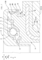
FIGS. 2 and3 , an axial gap C is present between theupper case 2 and theupper spring seat 14. Theupper case 2 has a first upper-case wall surface 2A, a second upper-case wall surface 2B, and a third upper-case wall surface 2C. Thelower case 3 has a first lower-case wall surface 3A, a second lower-case wall surface 3B, and a third lower-case wall surface 3C. - Each of the first upper-
case wall surface 2A and the third upper-case wall surface 2C is an inner peripheral surface of theupper case 2. The second upper-case wall surface 2B is an annular surface of theupper case 2. Each of the first lower-case wall surface 3A and the third lower-case wall surface 3C is an outer peripheral surface of thelower case 3. The second lower-case wall surface 3B is an annular surface of the lower case. - The first lower-
case wall surface 3A faces the axial gap C. The second lower-case wall surface 3B extends toward the radially outer side RO from an upper end of the first lower-case wall surface 3A. The third lower-case wall surface 3C extends upward from an end E of the second lower-case wall surface 3B in the radially outer side RO. - The first upper-
case wall surface 2A faces an upper portion of the first lower-case wall surface 3A. The second upper-case wall surface 2B extends toward a radially inner side RI from an upper end of the first upper-case wall surface 2A. The third upper-case wall surface 2C extends upward from an end F of the second upper-case wall surface 2B in the radially inner side RI, and faces the third lower-case wall surface 3C. - In the examples respectively shown in
FIGS. 2 and3 , the first upper-case wall surface 2A faces: the upper portion of the first lower-case wall surface 3A; the end E of the second lower-case wall surface 3B in the radially outer side RO; and a lower portion of the third lower-case wall surface 3C. In addition, the third lower-case wall surface 3C faces: a lower portion of the third upper-case wall surface 2C; the end F of the second upper-case wall surface 2B in the radially inner side RI; and an upper portion of the first upper-case wall surface 2A. Therefore, water flow toward the outerdiameter side seal 9 flows from a first radial gap G1 between the third lower-case wall surface 3C and the first upper-case wall surface 2A to a second radial gap G2 that is smaller in diameter than the first radial gap G1, between the third lower-case wall surface 3C and the third upper-case wall surface 2C. -
FIG. 3 shows axial lengths J1, J2, J3, and J4 that satisfy the relationship of J1 < J2 < J3 < J4, but may also satisfy J2 = J3. In other words, it is sufficient, if J1 < J2 ≦ J3 < J4 is satisfied. When J2 = J3, the end E of the second lower-case wall surface 3B in the radially outer side RO and the end F of the second upper-case wall surface 2B in the radially inner side RI face each other in the radial direction R. - Furthermore,
FIG. 3 shows radii R1, R2, R3, and R4 that satisfy the relationship of R1 < R2 < R3 < R4. In a preferred embodiment, the length of the second radial gap G2 in the radial direction R, i.e., R3 - R2, is set to 2.0 mm or less. - When high-speed water such as muddy water enters through the axial gap C, the high-speed water bounces off the first lower-
case wall surface 3A, which is the outer peripheral surface of thelower case 3 and faces the axial gap C, and then hits the first upper-case wall surface 2A, which is the inner peripheral surface of theupper case 2. The water flow toward the outerdiameter side seal 9 hits the second upper-case wall surface 2B, which is the annular surface, and then passes through the second radial gap G2 between the third lower-case wall surface 3C and the third upper-case wall surface 2C. - Accordingly, the high-speed water hits the first lower-
case wall surface 3A that is the outer peripheral surface of the lower case and faces the axial gap C, the first upper-case wall surface 2A that is the inner peripheral surface of theupper case 2, and the second upper-case wall surface 2B that is the annular surface. Thus, the water force is attenuated and the direction of the water flow is dispersed. Then, the high-speed water passes through the second radial gap G2 to approach the outerdiameter side seal 9. Therefore, the deceleration of the high-speed water such as muddy water that has entered the axial gap C from the radially outer side RO before the water reaches the outerdiameter side seal 9 can be enhanced. This makes it possible to reduce a quantity of the water flowing around a lip of the outerdiameter side seal 9. - In a preferred embodiment, with respect to the shape shown in
FIG. 3 , the second lower-case wall surface 3B that is the annular surface is made to be inclined downward toward the radially outer side RO, so as to form, with the first lower-case wall surface 3A, an acute angle P (P < 90 degrees), as shown inFIG. 4 . In a further preferred embodiment, with respect to the shape shown inFIG. 3 , the second upper-case wall surface 2B that is the annular surface is made to be inclined downward toward the radially inner side RI, so as to form, with the first upper-case wall surface 2A, an acute angle Q (Q < 90 degrees), as shown inFIG. 5 . - The angle P and/or the angle Q is formed in an acute angle, thereby further enhancing the deceleration of high-speed water such as muddy water that has entered the axial gap C from the radially outer side RO before the water reaches the outer
diameter side seal 9. - For example, a lower end of the
upper case 2 in the structure ofFIG. 2 may be provided with an inward protruding piece H that has an annular shape and protrudes toward the radially inner side RI as shown inFIG. 6 . The inward protruding piece H is provided, thereby preventing theupper case 2 and thelower case 3 from being separated. - An analysis model of the present invention, which imitates a shape of the strut bearing device A shown in
FIG. 6 , and an analysis model of a conventional shape, which imitates a shape of the strut bearing device shown inFIG. 1 ofPTL 1, were prepared. In the analysis model of the present invention, the axial lengths shown inFIG. 3 satisfy J3 < J4, whereas in the analysis model of the conventional shape, the axial lengths satisfy J3 > J4. Flow rates of water that has entered through the axial gap C around the lip of the outerdiameter side seal 9 were compared between the analysis model of the present invention and the analysis model of the conventional shape. - To facilitate the analysis, an underwater environment was adopted, and an injection port (diameter: 2 mm) for injecting water was arranged on the axial gap C in the radially outer side RO to face the radially inner side RI. The analysis was performed under conditions that high-speed water with a flow rate of 8 m/s was injected from the injection port.
- The flow rate around the lip of the outer
diameter side seal 9 was 0.80 for the analysis model of the present invention, in comparison with 1.0 for the analysis model of the conventional shape. Accordingly, the present invention can enhance the deceleration of the high-speed water that has entered the axial gap C before the water reaches the outerdiameter side seal 9. - In a strut bearing device B according to
Embodiment 2 of the present invention as shown inFIG. 7 , the same reference numerals as those ofEmbodiment 1 inFIGS. 1 to 3 indicate the same or corresponding components, parts, locations, and the like. - The
lower case 3 of the strut bearing 1 that is the strut bearing device B is made of a synthetic resin and contains a core metal M. The core metal M is made of steel, and is formed by pressing a steel plate. Depending on the necessity, quench-hardening is performed after the processing. Thelower case 3 is formed by injection molding using the core metal M as an insert work. - The
lower case 3 has acylindrical portion 3D and anannular portion 3E extending toward the radially outer side RO from an upper part of thecylindrical portion 3D, and contains the core metal M, thereby functioning as an upper spring seat of thespring support component 13 that supports the upper end of the coil spring 11 (seeFIG. 1 ). - There is an axial gap D between the
upper case 2 and thelower case 3. The first upper-case wall surface 2A, the second upper-case wall surface 2B, and the third upper-case wall surface 2C of theupper case 2, as well as the first lower-case wall surface 3A, the second lower-case wall surface 3B, and the third lower-case wall surface 3C of thelower case 3 are the same as those inEmbodiment 1. Therefore, the strut bearing device B ofEmbodiment 2 exhibits the same operational effects as the strut bearing device A ofEmbodiment 1. - The above description of Embodiments is merely illustrative and is not intended to limit the invention. Various improvements and modifications can be made without departing from the scope of the invention.
Claims (4)
- A strut bearing device, comprising: a strut bearing; and an upper spring seat that is a spring support component supporting an upper end of a coil spring, whereinthe strut bearing includes an upper case, a lower case, an upper raceway ring held by the upper case, a lower raceway ring held by the lower case, rolling elements that roll between the upper raceway ring and the lower raceway ring, and a seal positioned in a radially outer side of the rolling elements,the upper spring seat is in contact with the lower case,an axial gap is present between the upper case and the upper spring seat,the upper case has a first upper-case wall surface, a second upper-case wall surface, and a third upper-case wall surface,each of the first upper-case wall surface and the third upper-case wall surface is an inner peripheral surface of the upper case,the second upper-case wall surface is an annular surface of the upper case,the lower case has a first lower-case wall surface, a second lower-case wall surface, and a third lower-case wall surface,each of the first lower-case wall surface and the third lower-case wall surface is an outer peripheral surface of the lower case,the second lower-case wall surface is an annular surface of the lower case,the first lower-case wall surface faces the axial gap,the second lower-case wall surface extends radially outward from an upper end of the first lower-case wall surface,the third lower-case wall surface extends upward from a radially outer end of the second lower-case wall surface,the first upper-case wall surface faces an upper portion of the first lower-case wall surface,the second upper-case wall surface extends radially inward from an upper end of the first upper-case wall surface, andthe third upper-case wall surface extends upward from a radially inner end of the second upper-case wall surface, and faces the third lower-case wall surface.
- A strut bearing device comprising: an upper case; a lower case; an upper raceway ring held by the upper case; a lower raceway ring held by the lower case; rolling elements that roll between the upper raceway ring and the lower raceway ring; and a seal positioned in a radially outer side of the rolling element, whereinthe lower case is made of a synthetic resin containing a core metal, has a cylindrical portion and an annular portion extending radially outward from an upper portion of the cylindrical portion, and functions as a spring support component that supports an upper end of a coil spring;an axial gap is present between the upper case and the lower case, the upper case has a first upper-case wall surface, a second upper-case wall surface, and a third upper-case wall surface,each of the first upper-case wall surface and the third upper-case wall surface is an inner peripheral surface of the upper case,the second upper-case wall surface is an annular surface of the upper case,the lower case has a first lower-case wall surface, a second lower-case wall surface, and a third lower-case wall surface,each of the first lower-case wall surface and the third lower-case wall surface is an outer peripheral surface of the lower case,the second lower-case wall surface is an annular surface of the lower case,the first lower-case wall surface faces the axial gap,the second lower-case wall surface extends radially outward from an upper end of the first lower-case wall surface,the third lower-case wall surface extends upward from a radially outer end of the second lower-case wall surface,the first upper-case wall surface faces an upper portion of the first lower-case wall surface,the second upper-case wall surface extends radially inward from an upper end of the first upper-case wall surface, andthe third upper-case wall surface extends upward from a radially inner end of the second upper-case wall surface and faces the third lower-case wall surface.
- The strut bearing device according to claim 1 or 2, wherein
at least one of an angle formed by the first lower-case wall surface and the second lower-case wall surface and an angle formed by the first upper-case wall surface and the second upper-case wall surface is an acute angle. - A vehicle strut suspension comprising the strut bearing device according to claim 1 or 2.
Applications Claiming Priority (1)
| Application Number | Priority Date | Filing Date | Title |
|---|---|---|---|
| JP2023175481A JP2025065939A (en) | 2023-10-10 | 2023-10-10 | Strut bearing device and strut suspension for vehicle |
Publications (1)
| Publication Number | Publication Date |
|---|---|
| EP4552869A1 true EP4552869A1 (en) | 2025-05-14 |
Family
ID=93563391
Family Applications (1)
| Application Number | Title | Priority Date | Filing Date |
|---|---|---|---|
| EP24205144.9A Pending EP4552869A1 (en) | 2023-10-10 | 2024-10-08 | Strut bearing device and vehicle strut suspension |
Country Status (4)
| Country | Link |
|---|---|
| US (1) | US12618434B2 (en) |
| EP (1) | EP4552869A1 (en) |
| JP (1) | JP2025065939A (en) |
| CN (1) | CN119802079A (en) |
Citations (4)
| Publication number | Priority date | Publication date | Assignee | Title |
|---|---|---|---|---|
| WO2020016347A1 (en) * | 2018-07-18 | 2020-01-23 | Ntn-Snr Roulements | Bumpstop for a motor vehicle |
| US10753389B2 (en) | 2018-10-16 | 2020-08-25 | Aktiebolaget Skf | Suspension thrust bearing device |
| CN116104864A (en) * | 2021-11-11 | 2023-05-12 | 中西金属工业株式会社 | Thrust bearing arrangement and MacPherson suspension of the vehicle |
| FR3133420A1 (en) * | 2022-03-08 | 2023-09-15 | Skf | Sealed suspension stop device |
Family Cites Families (8)
| Publication number | Priority date | Publication date | Assignee | Title |
|---|---|---|---|---|
| FR2901737B1 (en) * | 2006-06-02 | 2008-08-29 | Skf Ab | SUSPENSION STOPPER DEVICE AND FORCE LEG |
| FR2934656B1 (en) * | 2008-08-01 | 2013-05-17 | Skf Ab | SUSPENSION STOP DEVICE AND FORCE LEG. |
| FR2954434B1 (en) * | 2009-12-23 | 2012-01-20 | Skf Ab | SUSPENSION STOP DEVICE, IN PARTICULAR FOR A MOTOR VEHICLE FORCE LEG. |
| US10746224B2 (en) * | 2016-07-19 | 2020-08-18 | Oiles Corporation | Slide bearing |
| DE102016222055A1 (en) * | 2016-11-10 | 2018-05-17 | Schaeffler Technologies AG & Co. KG | Strut mounts |
| DE102017208997A1 (en) * | 2017-05-29 | 2018-11-29 | Aktiebolaget Skf | AUFHÄNGUNGSAXIALLAGEREINHEIT |
| DE102020200587A1 (en) * | 2020-01-20 | 2021-07-22 | Aktiebolaget Skf | Suspension thrust bearing device |
| DE102020201405A1 (en) * | 2020-02-05 | 2021-08-05 | Aktiebolaget Skf | Suspension thrust bearing device with blocked seal |
-
2023
- 2023-10-10 JP JP2023175481A patent/JP2025065939A/en active Pending
-
2024
- 2024-09-27 CN CN202411357821.0A patent/CN119802079A/en active Pending
- 2024-10-07 US US18/907,978 patent/US12618434B2/en active Active
- 2024-10-08 EP EP24205144.9A patent/EP4552869A1/en active Pending
Patent Citations (4)
| Publication number | Priority date | Publication date | Assignee | Title |
|---|---|---|---|---|
| WO2020016347A1 (en) * | 2018-07-18 | 2020-01-23 | Ntn-Snr Roulements | Bumpstop for a motor vehicle |
| US10753389B2 (en) | 2018-10-16 | 2020-08-25 | Aktiebolaget Skf | Suspension thrust bearing device |
| CN116104864A (en) * | 2021-11-11 | 2023-05-12 | 中西金属工业株式会社 | Thrust bearing arrangement and MacPherson suspension of the vehicle |
| FR3133420A1 (en) * | 2022-03-08 | 2023-09-15 | Skf | Sealed suspension stop device |
Also Published As
| Publication number | Publication date |
|---|---|
| US20250116297A1 (en) | 2025-04-10 |
| CN119802079A (en) | 2025-04-11 |
| US12618434B2 (en) | 2026-05-05 |
| JP2025065939A (en) | 2025-04-22 |
Similar Documents
| Publication | Publication Date | Title |
|---|---|---|
| JP7381887B2 (en) | Strut bearings and vehicle strut suspensions | |
| JP5635091B2 (en) | Thrust bearing and vehicle suspension | |
| CN102046404B (en) | Suspension buffer block and pillar device | |
| US8496383B2 (en) | Bump stop and associated MacPherson strut | |
| CN102791501B (en) | For thrust bearing and the suspension of vehicle | |
| CN112644238B (en) | Suspension thrust bearing device and suspension strut equipped with such a device | |
| CN111306186B (en) | Suspension thrust bearing device and suspension strut equipped with such a device | |
| CN102822542A (en) | Axial thrust bearing device with a mobile sealing ring | |
| US9869351B2 (en) | Spring strut bearing | |
| JP7736231B2 (en) | Strut bearing device and strut suspension for vehicle | |
| JP7719443B2 (en) | Strut bearing device and strut suspension for vehicle | |
| CN111457013A (en) | Suspension thrust bearing device and suspension strut equipped with such device | |
| KR20230015837A (en) | Suspension abutment device with seal | |
| US12618434B2 (en) | Strut bearing device and vehicle strut suspension | |
| US12502920B2 (en) | Bump stop device with seal | |
| JP2007016972A (en) | Thrust bearing and vehicle suspension | |
| JP7365555B2 (en) | How to manufacture the lower case of a strut bearing | |
| JP2022088153A (en) | Strut bearing, and strut type suspension of vehicle | |
| JP2023085639A (en) | Strut bearings and vehicle strut suspensions | |
| JP2024053432A (en) | Strut bearing device and strut suspension for vehicle | |
| CN113389808B (en) | Support rod bearing and support rod type suspension of vehicle | |
| JP2025077531A (en) | Strut bearing and strut suspension of vehicle | |
| JP2024053431A (en) | Strut bearing device and strut suspension for vehicle | |
| WO2011026759A1 (en) | Bump stop device and macpherson strut | |
| KR102960787B1 (en) | Suspension thrust bearing device with seal comprising at least an elastic lip |
Legal Events
| Date | Code | Title | Description |
|---|---|---|---|
| PUAI | Public reference made under article 153(3) epc to a published international application that has entered the european phase |
Free format text: ORIGINAL CODE: 0009012 |
|
| STAA | Information on the status of an ep patent application or granted ep patent |
Free format text: STATUS: THE APPLICATION HAS BEEN PUBLISHED |
|
| AK | Designated contracting states |
Kind code of ref document: A1 Designated state(s): AL AT BE BG CH CY CZ DE DK EE ES FI FR GB GR HR HU IE IS IT LI LT LU LV MC ME MK MT NL NO PL PT RO RS SE SI SK SM TR |
|
| STAA | Information on the status of an ep patent application or granted ep patent |
Free format text: STATUS: REQUEST FOR EXAMINATION WAS MADE |
|
| 17P | Request for examination filed |
Effective date: 20250922 |