EP4552863A1 - Tire - Google Patents
Tire Download PDFInfo
- Publication number
- EP4552863A1 EP4552863A1 EP24206313.9A EP24206313A EP4552863A1 EP 4552863 A1 EP4552863 A1 EP 4552863A1 EP 24206313 A EP24206313 A EP 24206313A EP 4552863 A1 EP4552863 A1 EP 4552863A1
- Authority
- EP
- European Patent Office
- Prior art keywords
- sipe
- tire
- axial direction
- land portion
- tire axial
- Prior art date
- Legal status (The legal status is an assumption and is not a legal conclusion. Google has not performed a legal analysis and makes no representation as to the accuracy of the status listed.)
- Pending
Links
Images





Classifications
-
- B—PERFORMING OPERATIONS; TRANSPORTING
- B60—VEHICLES IN GENERAL
- B60C—VEHICLE TYRES; TYRE INFLATION; TYRE CHANGING; CONNECTING VALVES TO INFLATABLE ELASTIC BODIES IN GENERAL; DEVICES OR ARRANGEMENTS RELATED TO TYRES
- B60C11/00—Tyre tread bands; Tread patterns; Anti-skid inserts
- B60C11/03—Tread patterns
- B60C11/12—Tread patterns characterised by the use of narrow slits or incisions, e.g. sipes
- B60C11/1236—Tread patterns characterised by the use of narrow slits or incisions, e.g. sipes with special arrangements in the tread pattern
-
- B—PERFORMING OPERATIONS; TRANSPORTING
- B60—VEHICLES IN GENERAL
- B60C—VEHICLE TYRES; TYRE INFLATION; TYRE CHANGING; CONNECTING VALVES TO INFLATABLE ELASTIC BODIES IN GENERAL; DEVICES OR ARRANGEMENTS RELATED TO TYRES
- B60C11/00—Tyre tread bands; Tread patterns; Anti-skid inserts
- B60C11/03—Tread patterns
- B60C11/0304—Asymmetric patterns
-
- B—PERFORMING OPERATIONS; TRANSPORTING
- B60—VEHICLES IN GENERAL
- B60C—VEHICLE TYRES; TYRE INFLATION; TYRE CHANGING; CONNECTING VALVES TO INFLATABLE ELASTIC BODIES IN GENERAL; DEVICES OR ARRANGEMENTS RELATED TO TYRES
- B60C11/00—Tyre tread bands; Tread patterns; Anti-skid inserts
- B60C11/03—Tread patterns
- B60C11/0306—Patterns comprising block rows or discontinuous ribs
-
- B—PERFORMING OPERATIONS; TRANSPORTING
- B60—VEHICLES IN GENERAL
- B60C—VEHICLE TYRES; TYRE INFLATION; TYRE CHANGING; CONNECTING VALVES TO INFLATABLE ELASTIC BODIES IN GENERAL; DEVICES OR ARRANGEMENTS RELATED TO TYRES
- B60C11/00—Tyre tread bands; Tread patterns; Anti-skid inserts
- B60C11/03—Tread patterns
- B60C2011/0337—Tread patterns characterised by particular design features of the pattern
- B60C2011/0339—Grooves
- B60C2011/0341—Circumferential grooves
-
- B—PERFORMING OPERATIONS; TRANSPORTING
- B60—VEHICLES IN GENERAL
- B60C—VEHICLE TYRES; TYRE INFLATION; TYRE CHANGING; CONNECTING VALVES TO INFLATABLE ELASTIC BODIES IN GENERAL; DEVICES OR ARRANGEMENTS RELATED TO TYRES
- B60C11/00—Tyre tread bands; Tread patterns; Anti-skid inserts
- B60C11/03—Tread patterns
- B60C2011/0337—Tread patterns characterised by particular design features of the pattern
- B60C2011/0339—Grooves
- B60C2011/0358—Lateral grooves, i.e. having an angle of 45 to 90 degees to the equatorial plane
-
- B—PERFORMING OPERATIONS; TRANSPORTING
- B60—VEHICLES IN GENERAL
- B60C—VEHICLE TYRES; TYRE INFLATION; TYRE CHANGING; CONNECTING VALVES TO INFLATABLE ELASTIC BODIES IN GENERAL; DEVICES OR ARRANGEMENTS RELATED TO TYRES
- B60C11/00—Tyre tread bands; Tread patterns; Anti-skid inserts
- B60C11/03—Tread patterns
- B60C2011/0337—Tread patterns characterised by particular design features of the pattern
- B60C2011/0339—Grooves
- B60C2011/0381—Blind or isolated grooves
-
- B—PERFORMING OPERATIONS; TRANSPORTING
- B60—VEHICLES IN GENERAL
- B60C—VEHICLE TYRES; TYRE INFLATION; TYRE CHANGING; CONNECTING VALVES TO INFLATABLE ELASTIC BODIES IN GENERAL; DEVICES OR ARRANGEMENTS RELATED TO TYRES
- B60C11/00—Tyre tread bands; Tread patterns; Anti-skid inserts
- B60C11/03—Tread patterns
- B60C2011/0337—Tread patterns characterised by particular design features of the pattern
- B60C2011/0386—Continuous ribs
- B60C2011/0388—Continuous ribs provided at the equatorial plane
-
- B—PERFORMING OPERATIONS; TRANSPORTING
- B60—VEHICLES IN GENERAL
- B60C—VEHICLE TYRES; TYRE INFLATION; TYRE CHANGING; CONNECTING VALVES TO INFLATABLE ELASTIC BODIES IN GENERAL; DEVICES OR ARRANGEMENTS RELATED TO TYRES
- B60C11/00—Tyre tread bands; Tread patterns; Anti-skid inserts
- B60C11/03—Tread patterns
- B60C11/12—Tread patterns characterised by the use of narrow slits or incisions, e.g. sipes
- B60C11/1204—Tread patterns characterised by the use of narrow slits or incisions, e.g. sipes with special shape of the sipe
- B60C2011/1209—Tread patterns characterised by the use of narrow slits or incisions, e.g. sipes with special shape of the sipe straight at the tread surface
-
- B—PERFORMING OPERATIONS; TRANSPORTING
- B60—VEHICLES IN GENERAL
- B60C—VEHICLE TYRES; TYRE INFLATION; TYRE CHANGING; CONNECTING VALVES TO INFLATABLE ELASTIC BODIES IN GENERAL; DEVICES OR ARRANGEMENTS RELATED TO TYRES
- B60C11/00—Tyre tread bands; Tread patterns; Anti-skid inserts
- B60C11/03—Tread patterns
- B60C11/12—Tread patterns characterised by the use of narrow slits or incisions, e.g. sipes
- B60C11/1236—Tread patterns characterised by the use of narrow slits or incisions, e.g. sipes with special arrangements in the tread pattern
- B60C2011/1254—Tread patterns characterised by the use of narrow slits or incisions, e.g. sipes with special arrangements in the tread pattern with closed sipe, i.e. not extending to a groove
Definitions
- the present invention relates to a tire.
- Japanese Laid-Open Patent Publication No. 2019-194051 describes a tire provided with inner shoulder sipes on an inner shoulder land portion.
- the inner shoulder sipes include second end sipes each extending inward in the tire axial direction from one end thereof, and third end sipes each extending outward in the tire axial direction from one end thereof.
- a region where no sipe is provided is provided between the one ends of the second end sipes and the one ends of the third end sipes in the tire circumferential direction.
- the present invention has been made in view of the above-described problem, and a main object of the present invention is to provide a tire capable of improving noise performance while maintaining steering stability.
- a tire includes a tread portion, wherein: the tread portion includes a first tread end and a first shoulder land portion including the first tread end; a plurality of sipe groups each including four sipes extending in a tire axial direction are arranged in a tire circumferential direction on the first shoulder land portion; in each of the sipe groups, the four sipes include a first sipe, a second sipe adjacent to an outer side in the tire axial direction of the first sipe via a first land portion where no groove and no sipe are provided between the first sipe and the second sipe, a third sipe adjacent to the first sipe in the tire circumferential direction, and a fourth sipe adjacent to the outer side in the tire axial direction of the third sipe via a second land portion where no groove and no sipe are provided between the third sipe and the fourth sipe; and a center in the tire axial direction of the second land portion is located at a position different in the tire axial direction from a center in the tire axial direction of the first land portion.
- the tire of the present invention is capable of improving noise performance while maintaining steering stability.
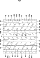
- FIG. 1 is an enlarged plan view of a tread portion 2 of a tire 1 showing one embodiment of the present invention.
- the present invention is suitably used for a pneumatic tire for a passenger car such as an SUV (Sport Utility Vehicle).
- the present invention may be used for pneumatic tires for a light truck and for a heavy duty vehicle and a non-pneumatic tire the interior of which is not filled with pressurized air.
- the standardized state is a state where the tire 1 is fitted on a standardized rim (not shown) and inflated to a standardized internal pressure and no load is applied to the tire 1.
- the standardized state means a standard use state, corresponding to the purpose of use of the tire, where the tire is not mounted on a vehicle and no load is applied to the tire.
- the "standardized rim” is a rim that is defined, in a standard system including a standard on which the tire 1 is based, by the standard for each tire, and is, for example, the "standard rim” in the JATMA standard, the "Design Rim” in the TRA standard, or the “Measuring Rim” in the ETRTO standard.
- the "standardized internal pressure” is an air pressure that is defined, in a standard system including a standard on which the tire 1 is based, by the standard for each tire, and is the “maximum air pressure” in the JATMA standard, the maximum value indicated in the table "TIRE LOAD LIMITS AT VARIOUS COLD INFLATION PRESSURES" in the TRA standard, or the “INFLATION PRESSURE” in the ETRTO standard.
- the tread portion 2 includes a first tread end T1 and a first shoulder land portion 5 including the first tread end T1.
- a plurality of sipe groups 6 each including four sipes extending in the tire axial direction are arranged in the tire circumferential direction.
- the "sipe” is a slit-like recess having a width Ws of less than 1.5 mm, and is clearly distinguished from grooves that are recesses having a groove width of 1.5 mm or more.
- the grooves include circumferential grooves and lateral grooves described later, etc.
- the sipes and the grooves are recesses provided on a tread surface 2a of the tread portion 2.
- the tread surface 2a is a surface that is in contact with a flat surface in a standardized load-applied state.
- the standardized load-applied state is a state where a standardized load is applied to the tire 1 in the standardized state and the tire 1 is brought into contact with the flat surface at a camber angle of 0°.
- the "standardized load” is a load that is defined, in a standard system including a standard on which the tire 1 is based, by the standard for each tire, and is the "maximum load capacity" in the JATMA standard, the maximum value indicated in the table "TIRE LOAD LIMITS AT VARIOUS COLD INFLATION PRESSURES" in the TRA standard, or the "LOAD CAPACITY" in the ETRTO standard.
- the four sipes include a first sipe 7, and a second sipe 9 adjacent to the outer side in the tire axial direction of the first sipe 7 via a first land portion 8 where no groove and no sipe are provided between the first sipe 7 and the second sipe 9.
- the four sipes also include a third sipe 10 adjacent to the first sipe 7 in the tire circumferential direction, and a fourth sipe 12 adjacent to the outer side in the tire axial direction of the third sipe 10 via a second land portion 11 where no groove and no sipe are provided between the third sipe 10 and the fourth sipe 12.
- Such first land portion 8 and second land portion 11 can suppress a decrease in the pattern stiffness of the first shoulder land portion 5, and further can maintain high steering stability.
- a center 11c in the tire axial direction of the second land portion 11 is located at a position different in the tire axial direction from a center 8c in the tire axial direction of the first land portion 8.
- the first land portion 8 and the second land portion 11 are each a land portion having high stiffness, and thus have an effect of suppressing vibration of the first shoulder land portion 5 upon release from ground contact at an early stage. Since the center 11c of the second land portion 11 is provided at a position different from the center 8c of the first land portion 8, the above vibration suppressing effect is exhibited over a wide range in the tire axial direction of the first shoulder land portion 5, so that noise performance during running can be improved.
- the first land portion 8 and the second land portion 11 also reduce pitch sound caused by contact between the sipes and a road surface. Since the center 11c of the second land portion 11 is located at a position different from the center 8c of the first land portion 8, the locations where pitch sound is generated by the respective sipes 7, 9, 10, and 12 are distributed, so that noise performance can be further improved.
- the center 11c of the second land portion 11 is located at a position different in the tire axial direction from the first land portion 8. In other words, it is preferable that the center 11c of the second land portion 11 does not overlap the first land portion 8 in the tire axial direction over the entire length of the first land portion 8. In the present embodiment, as shown in FIG. 1 , the second land portion 11 does not overlap the first land portion 8 in the tire axial direction over the entire length of the first land portion 8. Accordingly, the above-described effects are further effectively exhibited.
- the "second land portion 11 does not overlap the first land portion 8 in the tire axial direction over the entire length of the first land portion 8" means that an outer end 8e in the tire axial direction of the first land portion 8 is located at the same position in the tire axial direction as an inner end 11i in the tire axial direction of the second land portion 11 or is located inward of the inner end 11i in the tire axial direction.
- the "second land portion 11 does not overlap the first land portion 8 in the tire axial direction over the entire length of the first land portion 8" also means that an inner end 8i in the tire axial direction of the first land portion 8 is located at the same position in the tire axial direction as an outer end 11e in the tire axial direction of the second land portion 11 or is located outward of the outer end 11e in the tire axial direction.
- FIG. 2 is a plan view of the tread portion 2.
- the tread portion 2 of the present embodiment includes a second tread end T2, a second shoulder land portion 15, a first middle land portion 16, a second middle land portion 17, and a crown land portion 18.
- the tread portion 2 also includes, for example, a first shoulder circumferential groove 20, a second shoulder circumferential groove 21, a first crown circumferential groove 22, and a second crown circumferential groove 23.
- the first tread end T1 and the second tread end T2 are each at a position at which the tire 1 in the standardized load-applied state is in contact with the flat surface on the outermost side in the tire axial direction.
- the length in the tire axial direction between the first tread end T1 and the second tread end T2 is a tread width TW.
- the second shoulder land portion 15 of the present embodiment includes the second tread end T2.
- the first middle land portion 16 is, for example, adjacent to the first shoulder land portion 5 in the tire axial direction.
- the second middle land portion 17 of the present embodiment is adjacent to the second shoulder land portion 15 in the tire axial direction.
- the crown land portion 18 is, for example, located between the first middle land portion 16 and the second middle land portion 17 and includes a tire equator C.
- the first shoulder circumferential groove 20 demarcates the first shoulder land portion 5 and the first middle land portion 16.
- the second shoulder circumferential groove 21 demarcates the second shoulder land portion 15 and the second middle land portion 17.
- the first crown circumferential groove 22 demarcates the first middle land portion 16 and the crown land portion 18.
- the second crown circumferential groove 23 demarcates the second middle land portion 17 and the crown land portion 18.
- the respective circumferential grooves 20 to 23 extend in the tire circumferential direction.
- the first shoulder circumferential groove 20, the first crown circumferential groove 22, and the second crown circumferential groove 23 of the present embodiment each include a main portion 24 extending continuously parallel to the tire circumferential direction, and projection portions 25 each projecting from the main portion 24 toward a land portion side. Such projection portions 25 disturb and reduce air column resonance in the circumferential groove.
- the second shoulder circumferential groove 21 is formed, for example, only with a main portion 24.
- each projection portion 25 decreases in a direction away from the main portion 24, for example.
- Such projection portions 25 can suppress a significant decrease in the stiffness (pattern stiffness) of each land portion.
- Each projection portion 25 is formed, for example, in a trapezoidal shape, more specifically, in an isosceles trapezoidal shape.
- the projection portion 25 includes a pair of inclined portions K, K whose projection lengths from the main portion 24 change continuously, and an equal-length portion H (shown in FIG. 7 ) which connects both inclined portions K and has a constant projection length.
- the projection portions 25 of the present embodiment include first projection portions 25A, second projection portions 25B, third projection portions 25C, and fourth projection portions 25D.
- Each first projection portion 25A is provided, for example, so as to project from the main portion 24 of the first shoulder circumferential groove 20 toward the first tread end T1 side.
- Each second projection portion 25B is provided, for example, so as to project from the main portion 24 of the first shoulder circumferential groove 20 toward the tire equator C side.
- Each third projection portion 25C is provided, for example, so as to project from the main portion 24 of the first crown circumferential groove 22 toward the tire equator C side.
- Each fourth projection portion 25D is provided, for example, so as to project from the main portion 24 of the second crown circumferential groove 23 toward the tire equator C side.
- Each first projection portion 25A and each second projection portion 25B overlap in the tire circumferential direction, for example. Accordingly, the effect of disturbing air column resonance is enhanced.
- an inclined portion K1 on one side in the tire circumferential direction of the first projection portion 25A and an inclined portion K2 on the other side in the tire circumferential direction of the second projection portion 25B overlap in the tire circumferential direction.
- each third projection portion 25C and each fourth projection portion 25D overlap in the tire circumferential direction, for example.
- the ratio (Wb/Wa) between a maximum length Wa in the tire circumferential direction and a maximum length (projection length) Wb in the tire axial direction of the projection portion 25 is preferably not less than 0.10 and further preferably not less than 0.15, and is preferably not greater than 0.30 and further preferably not greater than 0.35.
- a groove width Wm of each of the circumferential grooves 20 to 23 is preferably not less than 2.0% and further preferably not less than 2.5% of the tread width TW, and is preferably not greater than 5.0% and further preferably not greater than 4.5% of the tread width TW.
- the groove depth (not shown) of each of the circumferential grooves 20 to 23 is preferably not less than 6.0 mm and further preferably not less than 6.5 mm, and is preferably not greater than 8.5 mm and further preferably not greater than 8.0 mm.
- the groove width Wm of each of the circumferential grooves 20 to 23 is specified as the width of the main portion 24.
- the tread portion 2 of the present embodiment also has a designated mounting direction to a vehicle.
- the first tread end T1 is an inner tread end located on the inner side of the vehicle when the tire 1 is mounted to the vehicle.
- the second tread end T2 is an outer tread end located on the outer side of the vehicle when the tire 1 is mounted to the vehicle.
- the tread portion 2 is not limited to such a mode.
- the second sipe 9 is located on a virtual extension line v1 obtained by extending the first sipe 7 outward in the tire axial direction.
- Such first sipe 7 and second sipe 9 act to maintain high edge effects of the respective sipes 7 and 9 while appropriately decreasing the stiffness of the first shoulder land portion 5.
- the "located on the virtual extension line v1" not only means that a maximum value Lx of a shortest separation distance Ln between the virtual extension line v1 and the second sipe 9 is 0 mm, but also includes the case where the maximum value Lx of the shortest separation distance Ln is 2 mm or less (shown in FIGS. 3(A) and 3(B)).
- FIG. 3(A) shows a mode in which the first sipe 7 extends straight
- FIG. 3(B) shows a mode in which the first sipe 7 extends in an arc
- the "virtual extension line v1" is specified as an arc passing through three points E1 to E3 on a width center line 7c of the first sipe 7 and having a single radius of curvature (including a straight line whose radius of curvature is ⁇ ).
- the three points E1 to E3 are the inner end, the outer end, and the center in the tire axial direction of the width center line 7c.
- a width center line 9c of the second sipe 9 overlaps the virtual extension line v1 over the entire length thereof.
- the fourth sipe 12 is located on a virtual extension line v2 obtained by extending the third sipe 10 outward in the tire axial direction. Accordingly, the above-described effects are more effectively exhibited.
- the "located on the virtual extension line v2" is defined in the same manner as the "located on the virtual extension line v1".
- a width center line 12c of the fourth sipe 12 overlaps the virtual extension line v2 over the entire length thereof.
- An outer end 9e in the tire axial direction of the second sipe 9 and an outer end 12e in the tire axial direction of the fourth sipe 12 are located, for example, inward of the first tread end T1 in the tire axial direction. Accordingly, a decrease in the stiffness around the first tread end T1 is suppressed, so that steering stability is enhanced.
- An inner end 7i in the tire axial direction of the first sipe 7 and an inner end 10i in the tire axial direction of the third sipe 10 are connected to the first shoulder circumferential groove 20, for example.
- Such first sipe 7 and third sipe 10 have an effect of disturbing air column resonance in the first shoulder circumferential groove 20, so that noise performance is improved.
- An angle ⁇ 1 of each of the four sipes with respect to the tire axial direction is preferably not greater than 10 degrees and further preferably not greater than 5 degrees.
- Such sipes 7, 9, 10, and 12 are easily misaligned with the outer edge of the ground-contact shape of the tread portion 2, which tends to be a lateral elliptical shape, and contribute to reduction of pitch sound.
- the angle ⁇ 1 of each of the sipes 7, 9, 10, and 12 is 0 degrees in the present embodiment.
- FIG. 4 is a plan view of the first shoulder land portion 5.
- a length La of the first land portion 8 is preferably not less than 20% and further preferably not less than 25% of a sum ⁇ n1 of the length La of the first land portion 8, a length L1 of the first sipe 7, and a length L2 of the second sipe 9, and is preferably not greater than 40% and further preferably not greater than 35% of the sum ⁇ n1. Since the length La of the first land portion 8 is not less than 20% of the sum ⁇ n1, an excessive decrease in the stiffness of the first shoulder land portion 5 can be suppressed. Since the length La of the first land portion 8 is not greater than 40% of the sum ⁇ n1, the stiffness of the first shoulder land portion 5 can be appropriately decreased.
- Each of the lengths La, L1, and L2 is a length in the tire axial direction.
- a length Lb of the second land portion 11 is preferably not less than 20% and further preferably not less than 25% of a sum ⁇ n2 of the length Lb of the second land portion 11, a length L3 of the third sipe 10, and a length L4 of the fourth sipe 12, and is preferably not greater than 40% and further preferably not greater than 35% of the sum ⁇ n2.
- Each of the lengths Lb, L3, and L4 is a length in the tire axial direction.
- the sum ⁇ n1 is preferably not less than 50% and further preferably not less than 60% of a length Ls in the tire axial direction of the first shoulder land portion 5, and is preferably not greater than 90% and further preferably not greater than 80% of the length Ls. Since the sum ⁇ n1 is not less than 50% of the length Ls of the first shoulder land portion 5, the stiffness of the first shoulder land portion 5 can be appropriately decreased, so that pitch sound can be reduced. Since the sum ⁇ n1 is not greater than 90% of the length Ls of the first shoulder land portion 5, a significant decrease in the stiffness of the first shoulder land portion 5 can be suppressed and high steering stability can be maintained.
- the sum ⁇ n2 is preferably not less than 50% and further preferably not less than 60% of the length Ls of the first shoulder land portion 5, and is preferably not greater than 90% and further preferably not greater than 80% of the length Ls.
- the sum ⁇ n1 and the sum ⁇ n2 are the same length.
- the first shoulder land portion 5 includes, for example, a first shoulder lateral groove 30, a second shoulder lateral groove 31, and a connection sipe 32.
- a plurality of first shoulder lateral grooves 30, a plurality of second shoulder lateral grooves 31, and a plurality of connection sipes 32 are provided.
- the first shoulder lateral grooves 30, the second shoulder lateral grooves 31, and the connection sipes 32 extend in the tire axial direction, for example.
- a plurality of sipe groups 6 are arranged between the first shoulder lateral grooves 30 of the present embodiment adjacent in the tire circumferential direction.
- the first shoulder lateral grooves 30 and the second shoulder lateral grooves 31 are provided alternately in the tire circumferential direction, for example.
- the first shoulder lateral grooves 30 of the present embodiment traverse the first shoulder land portion 5. Accordingly, the first shoulder land portion 5 is divided into a plurality of first shoulder blocks 5R. On each first shoulder block 5R, a plurality of sipe groups 6 are provided, and, in the present embodiment, two sipe groups 6 are provided. On each first shoulder block 5R, the first sipes 7 are alternately arranged with, for example, the third sipes 10 in the tire circumferential direction.
- An angle ⁇ 2 of each of the plurality of first shoulder lateral grooves 30 with respect to the tire axial direction is preferably not greater than 10 degrees and further preferably not greater than 5 degrees.
- Such first shoulder lateral grooves 30 are easily misaligned with the outer edge of the ground-contact shape of the tread portion 2, which tends to be a lateral elliptical shape, and contribute to reduction of pitch sound.
- the angle ⁇ 2 of each first shoulder lateral groove 30 is 0 degrees in the present embodiment.
- of the difference between the angle ⁇ 1 of each of the four sipes and the angle ⁇ 2 of each of the plurality of first shoulder lateral grooves 30 is preferably not greater than 10 degrees and further preferably not greater than 5 degrees. Accordingly, the stiffness of the land portion between the four sipes and the first shoulder lateral grooves 30 is equalized in the tire axial direction, so that high steering stability is maintained.
- of the difference is 0 degrees.
- Each second shoulder lateral groove 31 is located so as to interpose the sipe groups 6 between the first shoulder lateral grooves 30 and the second shoulder lateral groove 31.
- the second shoulder lateral groove 31 extends inward in the tire axial direction from the first tread end T1 and terminates in the first shoulder block 5R.
- Such a second shoulder lateral groove 31 serves to appropriately decrease the stiffness of the first shoulder land portion 5.
- An inner end 31i in the tire axial direction of the second shoulder lateral groove 31 is preferably located inward, in the tire axial direction, of the inner end 11i in the tire axial direction of the second land portion 11 adjacent thereto in the tire circumferential direction. Accordingly, the second shoulder lateral groove 31 and the second land portion 11 overlap in the tire axial direction, so that the location where the stiffness of the first shoulder land portion 5 is excessively decreased is reduced in the tire axial direction. If the inner end 31i of the second shoulder lateral groove 31 is located excessively inward, in the tire axial direction, of the inner end 11i of the second land portion 11 adjacent thereto in the tire circumferential direction, the stiffness of the first shoulder land portion 5 is excessively decreased by the second shoulder lateral groove 31.
- a distance Lf in the tire axial direction between the inner end 31i of the second shoulder lateral groove 31 and the inner end 11i of the second land portion 11 adjacent thereto is preferably not less than 5% and further preferably not less than 10% of the length Lb of the second land portion 11, and is preferably not greater than 25% and further preferably not greater than 20% of the length Lb.
- An angle ⁇ 3 of each of the plurality of second shoulder lateral grooves 31 with respect to the tire axial direction is preferably not greater than 10 degrees and further preferably not greater than 5 degrees.
- Such second shoulder lateral grooves 31 are also easily misaligned with the outer edge of the ground-contact shape of the tread portion 2, which tends to be a lateral elliptical shape, and contribute to reduction of pitch sound.
- the angle ⁇ 3 of each second shoulder lateral groove 31 is 0 degrees in the present embodiment.
- Each second shoulder lateral groove 31 extends substantially parallel to the first shoulder lateral groove 30.
- Such a second shoulder lateral groove 31 equalizes the stiffness of the portion of the first shoulder land portion 5 surrounded by the first shoulder lateral groove 30 and the second shoulder lateral groove 31, over the tire axial direction, so that steering stability is enhanced.
- the "substantially parallel” means that the difference between one angle and the other angle is 0 degrees, and also includes the case where the absolute value of this difference is 5 degrees or less.
- connection sipe 32 connects the inner end 31i of the second shoulder lateral groove 31 and the first shoulder circumferential groove 20. Such a connection sipe 32 exhibits an effect of disturbing air column resonance in the first shoulder circumferential groove 20.
- each connection sipe 32 is connected to the first projection portion 25A of the first shoulder circumferential groove 20, more specifically, to the center in the tire circumferential direction of the equal-length portion H. Accordingly, the above-described effects are effectively exhibited.
- connection sipe 32 extends substantially parallel to the first shoulder lateral groove 30. Such a connection sipe 32 equalizes the stiffness of the portion of the first shoulder land portion 5 surrounded by the first shoulder lateral groove 30 and the connection sipe 32, over the tire axial direction, so that steering stability is enhanced.
- the length Ls in the tire axial direction of such a first shoulder land portion 5 is preferably not less than 4.5% and further preferably not less than 5% of the tread width TW, and is preferably not greater than 40% and further preferably not greater than 30% of the tread width TW.
- FIG. 5 is a plan view of the second shoulder land portion 15.
- the second shoulder land portion 15 is located on the outer side of the vehicle when the tire 1 is mounted to the vehicle.
- the second shoulder land portion 15 of the present embodiment includes a plurality of third shoulder lateral grooves 40 and a plurality of lateral sipes 41 each located between the third shoulder lateral grooves 40 adjacent in the tire circumferential direction.
- the third shoulder lateral grooves 40 traverse the second shoulder land portion 15, for example.
- Each third shoulder lateral groove 40 of the present embodiment includes a first portion 40a, a second portion 40b, and a third portion 40c.
- the first portion 40a extends outward in the tire axial direction from the second shoulder circumferential groove 21 with a constant groove width.
- the second portion 40b is connected to the second tread end T2 with a larger groove width than the first portion 40a.
- the third portion 40c connects the first portion 40a and the second portion 40b and has a groove width increasing continuously toward the second portion 40b.
- the first portion 40a and the second portion 40b extend substantially parallel to the first shoulder lateral groove 30. Such first portion 40a and second portion 40b are easily misaligned with the outer edge of the ground-contact shape of the tread portion 2, which tends to be a lateral elliptical shape, and contribute to reduction of pitch sound.
- the first portion 40a and the second portion 40b extend substantially parallel to the tire axial direction.
- An angle ⁇ 4a of the first portion 40a with respect to the tire axial direction and an angle ⁇ 4b of the second portion 40b with respect to the tire axial direction are 0 degrees in the present embodiment.
- a groove width W4a of the first portion 40a is preferably not less than 60% and further preferably not less than 65% of a groove width W4b of the second portion 40b, and is preferably not greater than 90% and further preferably not greater than 85% of the groove width W4b.
- the groove width W4a of the first portion 40a is preferably not less than 25% and further preferably not less than 30% of a groove width W1b of the second shoulder circumferential groove 21, and is preferably not greater than 45% and further preferably not greater than 40% of the groove width W1b.
- the sipe width Ws (shown in FIG. 1 ) is preferably not less than 0.1 times and further preferably not less than 0.3 times the groove width W4a of the first portion 40a, and is preferably not greater than 0.6 times and further preferably not greater than 0.5 times the groove width W4a.
- a length L6 in the tire axial direction of the first portion 40a is preferably not less than 70% and further preferably not less than 75% of a length L7 in the tire axial direction of the second portion 40b, and is preferably not greater than 90% and further preferably not greater than 85% of the length L7.
- the length L6 of the first portion 40a is preferably not less than 30% and further preferably not less than 35% of a length Lt in the tire axial direction of the second shoulder land portion 15, and is preferably not greater than 50% and further preferably not greater than 45% of the length Lt.
- Each lateral sipe 41 has, for example, at least an outer end 41e in the tire axial direction terminating in the second shoulder land portion 15.
- the lateral sipes 41 include first lateral sipes 41A, second lateral sipes 41B, and third lateral sipes 41C.
- Each first lateral sipe 41A is connected to the second shoulder circumferential groove 21.
- Each second lateral sipe 41B does not overlap the first lateral sipe 41A in the tire circumferential direction and the tire axial direction.
- Each third lateral sipe 41C is connected to the second shoulder circumferential groove 21 at a position different from the first lateral sipe 41A.
- the first lateral sipes 41A extend straight, for example.
- the first lateral sipes 41A of the present embodiment extend substantially parallel to the tire axial direction.
- Each second lateral sipe 41B has, for example, ends e1, e1 located in the second shoulder land portion 15.
- Each second lateral sipe 41B of the present embodiment is formed with a larger length in the tire axial direction than the first lateral sipe 41A.
- the second lateral sipes 41B extend substantially parallel to the tire axial direction.
- Each third lateral sipe 41C includes, for example, an inner third sipe portion 42a, an outer third sipe portion 42b, and an intermediate third sipe portion 42c.
- the inner third sipe portion 42a of the present embodiment extends substantially parallel to the tire axial direction from the second shoulder circumferential groove 21.
- the inner third sipe portion 42a is located, for example, on a virtual extension line v3 obtained by extending the second lateral sipe 41B inward in the tire axial direction.
- the outer third sipe portion 42b extends substantially parallel to the tire axial direction.
- the outer third sipe portion 42b is located, for example, on a virtual extension line v4 obtained by extending the first lateral sipe 41A outward in the tire axial direction.
- the intermediate third sipe portion 42c of the present embodiment connects the inner third sipe portion 42a and the outer third sipe portion 42b and extends so as to be inclined to one side with respect to the tire axial direction.
- the "located on the virtual extension line v3" and the “located on the virtual extension line v4" are defined in the same manner as the "located on the virtual extension line v1".
- FIG. 6 is a plan view of the first middle land portion 16 and the second middle land portion 17.
- the first middle land portion 16 of the present embodiment includes first middle lateral grooves 46, second middle lateral grooves 47, first middle circumferential sipes 48, and first middle lateral sipes 49.
- first middle lateral grooves 46 traverse the first middle land portion 16.
- the first middle lateral grooves 46 extend straight, for example.
- the first middle lateral grooves 46 of the present embodiment are inclined with respect to the tire axial direction.
- the second middle lateral grooves 47 extend from the first shoulder circumferential groove 20 toward the tire equator C side and terminate in the first middle land portion 16, for example.
- the second middle lateral grooves 47 of the present embodiment extend straight.
- the second middle lateral grooves 47 are inclined with respect to the tire axial direction.
- the second middle lateral grooves 47 are inclined, for example, in the same direction as the first middle lateral grooves 46.
- the second middle lateral grooves 47 extend substantially parallel to the first middle lateral grooves 46.
- the first middle circumferential sipes 48 of the present embodiment extend straight.
- the first middle circumferential sipes 48 extend, for example, substantially parallel to the tire circumferential direction.
- each first middle circumferential sipe 48 connects the first middle lateral groove 46 and the second middle lateral groove 47.
- the first middle circumferential sipe 48 is located, for example, at the substantial center in the tire axial direction of the first middle land portion 16.
- the "substantial center” means not only a center 16c in the tire axial direction of the first middle land portion 16 but also a region within 1% of the tread width TW (shown in FIG. 2 ) on each of both sides in the tire axial direction from the center 16c of the first middle land portion 16.
- each first middle circumferential sipe 48 is located at the center 16c of the first middle land portion 16.
- the first middle lateral sipes 49 extend straight, for example.
- the first middle lateral sipes 49 of the present embodiment are inclined with respect to the tire axial direction.
- the first middle lateral sipes 49 are inclined in the same direction as the first middle lateral grooves 46.
- the first middle lateral sipes 49 extend, for example, substantially parallel to the first middle lateral grooves 46.
- the first middle lateral sipes 49 include first lateral sipes 49A connected to the first shoulder circumferential groove 20 and second lateral sipes 49B connected to the first crown circumferential groove 22.
- Each first lateral sipe 49A of the present embodiment has an end portion e2 terminating in the first middle land portion 16.
- the first lateral sipes 49A include, for example, first main lateral sipes 50a connected to the main portion 24 of the first shoulder circumferential groove 20 and first sub-lateral sipes 50b connected to the second projection portions 25B of the first shoulder circumferential groove 20.
- Each first sub-lateral sipe 50b of the present embodiment is formed with a smaller length in the tire axial direction than the first main lateral sipe 50a.
- the second lateral sipes 49B include, for example, first end sipes 51a each having an end portion e3 terminating in the first middle land portion 16, and second connection sipes 51b connecting the second middle lateral grooves 47.
- Each first end sipe 51a and each second connection sipe 51b have substantially the same length in the tire axial direction in the present embodiment.
- the "substantially the same length in the tire axial direction” includes not only a mode in which a length A in the tire axial direction of one sipe and a length B in the tire axial direction of the other sipe are exactly the same, but also a mode in which the absolute value of the difference between the length A of the one sipe and the length B of the other sipe is 2 mm or less.
- Each first end sipe 51a is located, for example, on a virtual extension line v5 obtained by extending the first lateral sipe 49A inward in the tire axial direction.
- the "located on the virtual extension line v5" is defined in the same manner as the "located on the virtual extension line v1".
- the second middle land portion 17 of the present embodiment includes third middle lateral grooves 54, second middle circumferential sipes 55, and second middle lateral sipes 56.
- the third middle lateral grooves 54 of the present embodiment extend outward in the tire axial direction from the second crown circumferential groove 23 and terminate in the second middle land portion 17.
- the third middle lateral grooves 54 extend straight, for example.
- the third middle lateral grooves 54 are inclined with respect to the tire axial direction.
- the third middle lateral grooves 54 are inclined in the same direction as the first middle lateral grooves 46.
- the third middle lateral grooves 54 extend, for example, substantially parallel to the first middle lateral grooves 46.
- the second middle circumferential sipes 55 of the present embodiment extend straight.
- the second middle circumferential sipes 55 extend, for example, substantially parallel to the tire circumferential direction.
- each second middle circumferential sipe 55 connects the third middle lateral grooves 54, 54 adjacent in the tire circumferential direction.
- Each second middle circumferential sipe 55 is located, for example, at the substantial center in the tire axial direction of the second middle land portion 17.
- the "substantial center” is defined in the same manner as the "substantial center” of the first middle land portion 16.
- Each second middle circumferential sipe 55 of the present embodiment is located at a center 17c in the tire axial direction of the second middle land portion 17.
- the second middle lateral sipes 56 extend straight, for example.
- the second middle lateral sipes 56 are inclined with respect to the tire axial direction.
- the second middle lateral sipes 56 of the present embodiment are inclined in the same direction as the third middle lateral grooves 54.
- the second middle lateral sipes 56 extend, for example, substantially parallel to the third middle lateral grooves 54.
- the second middle lateral sipes 56 include third lateral sipes 56A connected to the second shoulder circumferential groove 21 and fourth lateral sipes 56B connected to the second crown circumferential groove 23.
- the third lateral sipes 56A of the present embodiment include second end sipes 57a each having an end portion e4 terminating in the second middle land portion 17, and third connection sipes 57b connecting the third middle lateral grooves 54.
- Each third connection sipe 57b is formed, for example, with a length in the tire axial direction smaller than that of the second end sipe 57a.
- Each fourth lateral sipe 56B of the present embodiment has an end portion e5 terminating in the second middle land portion 17.
- Each fourth lateral sipe 56B is located, for example, on a virtual extension line v6 obtained by extending the second end sipe 57a inward in the tire axial direction.
- the "located on the virtual extension line v6" is defined in the same manner as the "located on the virtual extension line v1".
- a width center line 56c of the fourth lateral sipe 56B overlaps the virtual extension line v6 over the entire length thereof.
- FIG. 7 is a plan view of the crown land portion 18.
- the crown land portion 18 of the present embodiment includes crown lateral grooves 60, a crown circumferential sipe 61, and crown lateral sipes 62.
- the crown lateral grooves 60 extend straight, for example.
- the crown lateral grooves 60 are inclined with respect to the tire axial direction.
- the crown lateral grooves 60 of the present embodiment are inclined in a direction opposite to that of the first middle lateral grooves 46 (shown in FIG. 6 ).
- Each crown lateral groove 60 includes, for example, an end portion e6 terminating in the crown land portion 18.
- the crown lateral grooves 60 include first crown lateral grooves 60A extending from the third projection portions 25C of the first crown circumferential groove 22 and second crown lateral grooves 60B extending from the fourth projection portions 25D of the second crown circumferential groove 23.
- Each of the first crown lateral grooves 60A and the second crown lateral grooves 60B extends from the end side in the tire circumferential direction of the projection portion 25 in the present embodiment, more specifically, from the position of the intersection of the equal-length portion H and the inclined portion K.
- the crown circumferential sipe 61 of the present embodiment extends straight.
- the crown circumferential sipe 61 extends, for example, parallel to the tire circumferential direction.
- the crown circumferential sipe 61 extends continuously in the tire circumferential direction.
- the crown circumferential sipe 61 is located, for example, at the substantial center in the tire axial direction of the crown land portion 18.
- the "substantial center” is defined in the same manner as the "substantial center” of the first middle land portion 16.
- the crown circumferential sipe 61 of the present embodiment is located at a center 18c in the tire axial direction of the crown land portion 18.
- the crown lateral sipes 62 extend straight, for example.
- the crown lateral sipes 62 of the present embodiment are inclined with respect to the tire axial direction. In the present embodiment, the crown lateral sipes 62 are inclined in the same direction as the crown lateral grooves 60.
- the crown lateral sipes 62 extend, for example, substantially parallel to the crown lateral grooves 60.
- Each crown lateral sipe 62 of the present embodiment includes an end portion e7 terminating in the crown land portion 18.
- the crown lateral sipes 62 include, for example, first crown lateral sipes 62A connected to the main portions 24 of the first crown circumferential groove 22 and second crown lateral sipes 62B connected to the main portions 24 of the second crown circumferential groove 23.
- each second crown lateral groove 60B is located on a virtual extension line v8 obtained by extending the first crown lateral sipe 62A in the tire axial direction.
- each first crown lateral groove 60A is located on a virtual extension line v9 obtained by extending the second crown lateral sipe 62B in the tire axial direction.
- the "located on the virtual extension line v8" and the “located on the virtual extension line v9" are defined in the same manner as the "located on the virtual extension line v1".
- the second crown lateral groove 60B overlaps the virtual extension line v8 over the entire length thereof.
- the first crown lateral groove 60A overlaps the virtual extension line v9 over the entire length thereof.
- the present invention includes the following aspects.
- a tire including a tread portion, wherein
- a length in the tire axial direction of the first land portion is 20% to 40% of a sum ⁇ n1 of the length in the tire axial direction of the first land portion, a length in the tire axial direction of the first sipe, and a length in the tire axial direction of the second sipe.
- first shoulder land portion includes a second shoulder lateral groove extending inward in the tire axial direction from the first tread end and having an inner end located in the first shoulder land portion, and a connection sipe connecting the inner end of the second shoulder lateral groove and the first shoulder circumferential groove.
Landscapes
- Engineering & Computer Science (AREA)
- Mechanical Engineering (AREA)
- Tires In General (AREA)
Abstract
Description
- The present invention relates to a tire.
-
Japanese Laid-Open Patent Publication No. 2019-194051 - In the tire of
Japanese Laid-Open Patent Publication No. 2019-194051 - The present invention has been made in view of the above-described problem, and a main object of the present invention is to provide a tire capable of improving noise performance while maintaining steering stability.
- A tire includes a tread portion, wherein: the tread portion includes a first tread end and a first shoulder land portion including the first tread end; a plurality of sipe groups each including four sipes extending in a tire axial direction are arranged in a tire circumferential direction on the first shoulder land portion; in each of the sipe groups, the four sipes include a first sipe, a second sipe adjacent to an outer side in the tire axial direction of the first sipe via a first land portion where no groove and no sipe are provided between the first sipe and the second sipe, a third sipe adjacent to the first sipe in the tire circumferential direction, and a fourth sipe adjacent to the outer side in the tire axial direction of the third sipe via a second land portion where no groove and no sipe are provided between the third sipe and the fourth sipe; and a center in the tire axial direction of the second land portion is located at a position different in the tire axial direction from a center in the tire axial direction of the first land portion.
- As a result of adopting the above configuration, the tire of the present invention is capable of improving noise performance while maintaining steering stability.
-
-
FIG. 1 is an enlarged plan view of a tread portion of one embodiment of the present invention; -
FIG. 2 is a plan view of the tread portion; -
FIGS. 3(A) and 3(B) are plan views for describing a virtual extension line; -
FIG. 4 is a plan view of a first shoulder land portion; -
FIG. 5 is a plan view of a second shoulder land portion; -
FIG. 6 is a plan view of a first middle land portion and a second middle land portion; and -
FIG. 7 is a plan view of a crown land portion. - Hereinafter, an embodiment of the present invention will be described with reference to the drawings. The drawings contain exaggerated expressions and expressions that differ from the dimensional ratio of the actual structure in order to help the understanding of the present invention. In addition, when there are a plurality of embodiments, the same or common elements are denoted by the same reference characters throughout the description, and the redundant description thereof is omitted.
-
FIG. 1 is an enlarged plan view of atread portion 2 of atire 1 showing one embodiment of the present invention. The present invention is suitably used for a pneumatic tire for a passenger car such as an SUV (Sport Utility Vehicle). However, the present invention may be used for pneumatic tires for a light truck and for a heavy duty vehicle and a non-pneumatic tire the interior of which is not filled with pressurized air. - In the present specification, unless otherwise specified, dimensions and the like of components of the
tire 1 are values measured in a standardized state. In the case of a pneumatic tire, the "standardized state" is a state where thetire 1 is fitted on a standardized rim (not shown) and inflated to a standardized internal pressure and no load is applied to thetire 1. In the case of a non-pneumatic tire or a tire for which various standards are not defined, the standardized state means a standard use state, corresponding to the purpose of use of the tire, where the tire is not mounted on a vehicle and no load is applied to the tire. - The "standardized rim" is a rim that is defined, in a standard system including a standard on which the
tire 1 is based, by the standard for each tire, and is, for example, the "standard rim" in the JATMA standard, the "Design Rim" in the TRA standard, or the "Measuring Rim" in the ETRTO standard. - The "standardized internal pressure" is an air pressure that is defined, in a standard system including a standard on which the
tire 1 is based, by the standard for each tire, and is the "maximum air pressure" in the JATMA standard, the maximum value indicated in the table "TIRE LOAD LIMITS AT VARIOUS COLD INFLATION PRESSURES" in the TRA standard, or the "INFLATION PRESSURE" in the ETRTO standard. - As shown in
FIG. 1 , thetread portion 2 includes a first tread end T1 and a firstshoulder land portion 5 including the first tread end T1. On the firstshoulder land portion 5, a plurality ofsipe groups 6 each including four sipes extending in the tire axial direction are arranged in the tire circumferential direction. In the present specification, the "sipe" is a slit-like recess having a width Ws of less than 1.5 mm, and is clearly distinguished from grooves that are recesses having a groove width of 1.5 mm or more. The grooves include circumferential grooves and lateral grooves described later, etc. The sipes and the grooves are recesses provided on atread surface 2a of thetread portion 2. Thetread surface 2a is a surface that is in contact with a flat surface in a standardized load-applied state. - The standardized load-applied state is a state where a standardized load is applied to the
tire 1 in the standardized state and thetire 1 is brought into contact with the flat surface at a camber angle of 0°. The "standardized load" is a load that is defined, in a standard system including a standard on which thetire 1 is based, by the standard for each tire, and is the "maximum load capacity" in the JATMA standard, the maximum value indicated in the table "TIRE LOAD LIMITS AT VARIOUS COLD INFLATION PRESSURES" in the TRA standard, or the "LOAD CAPACITY" in the ETRTO standard. - In each of the
sipe groups 6, the four sipes include afirst sipe 7, and asecond sipe 9 adjacent to the outer side in the tire axial direction of thefirst sipe 7 via afirst land portion 8 where no groove and no sipe are provided between thefirst sipe 7 and thesecond sipe 9. The four sipes also include athird sipe 10 adjacent to thefirst sipe 7 in the tire circumferential direction, and afourth sipe 12 adjacent to the outer side in the tire axial direction of thethird sipe 10 via asecond land portion 11 where no groove and no sipe are provided between thethird sipe 10 and thefourth sipe 12. Suchfirst land portion 8 andsecond land portion 11 can suppress a decrease in the pattern stiffness of the firstshoulder land portion 5, and further can maintain high steering stability. - A
center 11c in the tire axial direction of thesecond land portion 11 is located at a position different in the tire axial direction from acenter 8c in the tire axial direction of thefirst land portion 8. Thefirst land portion 8 and thesecond land portion 11 are each a land portion having high stiffness, and thus have an effect of suppressing vibration of the firstshoulder land portion 5 upon release from ground contact at an early stage. Since thecenter 11c of thesecond land portion 11 is provided at a position different from thecenter 8c of thefirst land portion 8, the above vibration suppressing effect is exhibited over a wide range in the tire axial direction of the firstshoulder land portion 5, so that noise performance during running can be improved. Thefirst land portion 8 and thesecond land portion 11 also reduce pitch sound caused by contact between the sipes and a road surface. Since thecenter 11c of thesecond land portion 11 is located at a position different from thecenter 8c of thefirst land portion 8, the locations where pitch sound is generated by therespective sipes - In order to further effectively exhibit the above-described effects, it is preferable that the
center 11c of thesecond land portion 11 is located at a position different in the tire axial direction from thefirst land portion 8. In other words, it is preferable that thecenter 11c of thesecond land portion 11 does not overlap thefirst land portion 8 in the tire axial direction over the entire length of thefirst land portion 8. In the present embodiment, as shown inFIG. 1 , thesecond land portion 11 does not overlap thefirst land portion 8 in the tire axial direction over the entire length of thefirst land portion 8. Accordingly, the above-described effects are further effectively exhibited. The "second land portion 11 does not overlap thefirst land portion 8 in the tire axial direction over the entire length of thefirst land portion 8" means that anouter end 8e in the tire axial direction of thefirst land portion 8 is located at the same position in the tire axial direction as aninner end 11i in the tire axial direction of thesecond land portion 11 or is located inward of theinner end 11i in the tire axial direction. The "second land portion 11 does not overlap thefirst land portion 8 in the tire axial direction over the entire length of thefirst land portion 8" also means that aninner end 8i in the tire axial direction of thefirst land portion 8 is located at the same position in the tire axial direction as anouter end 11e in the tire axial direction of thesecond land portion 11 or is located outward of theouter end 11e in the tire axial direction. -
FIG. 2 is a plan view of thetread portion 2. As shown inFIG. 2 , thetread portion 2 of the present embodiment includes a second tread end T2, a secondshoulder land portion 15, a firstmiddle land portion 16, a secondmiddle land portion 17, and acrown land portion 18. Thetread portion 2 also includes, for example, a first shouldercircumferential groove 20, a second shouldercircumferential groove 21, a first crowncircumferential groove 22, and a second crowncircumferential groove 23. - In the case of a pneumatic tire, the first tread end T1 and the second tread end T2 are each at a position at which the
tire 1 in the standardized load-applied state is in contact with the flat surface on the outermost side in the tire axial direction. The length in the tire axial direction between the first tread end T1 and the second tread end T2 is a tread width TW. - The second
shoulder land portion 15 of the present embodiment includes the second tread end T2. The firstmiddle land portion 16 is, for example, adjacent to the firstshoulder land portion 5 in the tire axial direction. The secondmiddle land portion 17 of the present embodiment is adjacent to the secondshoulder land portion 15 in the tire axial direction. Thecrown land portion 18 is, for example, located between the firstmiddle land portion 16 and the secondmiddle land portion 17 and includes a tire equator C. - The first shoulder
circumferential groove 20 demarcates the firstshoulder land portion 5 and the firstmiddle land portion 16. The second shouldercircumferential groove 21 demarcates the secondshoulder land portion 15 and the secondmiddle land portion 17. The firstcrown circumferential groove 22 demarcates the firstmiddle land portion 16 and thecrown land portion 18. The secondcrown circumferential groove 23 demarcates the secondmiddle land portion 17 and thecrown land portion 18. - The respective
circumferential grooves 20 to 23 extend in the tire circumferential direction. The firstshoulder circumferential groove 20, the firstcrown circumferential groove 22, and the secondcrown circumferential groove 23 of the present embodiment each include amain portion 24 extending continuously parallel to the tire circumferential direction, andprojection portions 25 each projecting from themain portion 24 toward a land portion side.Such projection portions 25 disturb and reduce air column resonance in the circumferential groove. The second shouldercircumferential groove 21 is formed, for example, only with amain portion 24. - The length in the tire circumferential direction of each
projection portion 25 decreases in a direction away from themain portion 24, for example.Such projection portions 25 can suppress a significant decrease in the stiffness (pattern stiffness) of each land portion. Eachprojection portion 25 is formed, for example, in a trapezoidal shape, more specifically, in an isosceles trapezoidal shape. In the present embodiment, theprojection portion 25 includes a pair of inclined portions K, K whose projection lengths from themain portion 24 change continuously, and an equal-length portion H (shown inFIG. 7 ) which connects both inclined portions K and has a constant projection length. - The
projection portions 25 of the present embodiment includefirst projection portions 25A,second projection portions 25B,third projection portions 25C, andfourth projection portions 25D. Eachfirst projection portion 25A is provided, for example, so as to project from themain portion 24 of the firstshoulder circumferential groove 20 toward the first tread end T1 side. Eachsecond projection portion 25B is provided, for example, so as to project from themain portion 24 of the firstshoulder circumferential groove 20 toward the tire equator C side. Eachthird projection portion 25C is provided, for example, so as to project from themain portion 24 of the firstcrown circumferential groove 22 toward the tire equator C side. Eachfourth projection portion 25D is provided, for example, so as to project from themain portion 24 of the secondcrown circumferential groove 23 toward the tire equator C side. - Each
first projection portion 25A and eachsecond projection portion 25B overlap in the tire circumferential direction, for example. Accordingly, the effect of disturbing air column resonance is enhanced. In the present embodiment, an inclined portion K1 on one side in the tire circumferential direction of thefirst projection portion 25A and an inclined portion K2 on the other side in the tire circumferential direction of thesecond projection portion 25B overlap in the tire circumferential direction. In addition, eachthird projection portion 25C and eachfourth projection portion 25D overlap in the tire circumferential direction, for example. - Although not particularly limited, the ratio (Wb/Wa) between a maximum length Wa in the tire circumferential direction and a maximum length (projection length) Wb in the tire axial direction of the
projection portion 25 is preferably not less than 0.10 and further preferably not less than 0.15, and is preferably not greater than 0.30 and further preferably not greater than 0.35. - A groove width Wm of each of the
circumferential grooves 20 to 23 is preferably not less than 2.0% and further preferably not less than 2.5% of the tread width TW, and is preferably not greater than 5.0% and further preferably not greater than 4.5% of the tread width TW. The groove depth (not shown) of each of thecircumferential grooves 20 to 23 is preferably not less than 6.0 mm and further preferably not less than 6.5 mm, and is preferably not greater than 8.5 mm and further preferably not greater than 8.0 mm. The groove width Wm of each of thecircumferential grooves 20 to 23 is specified as the width of themain portion 24. - The
tread portion 2 of the present embodiment also has a designated mounting direction to a vehicle. In the present embodiment, the first tread end T1 is an inner tread end located on the inner side of the vehicle when thetire 1 is mounted to the vehicle. The second tread end T2 is an outer tread end located on the outer side of the vehicle when thetire 1 is mounted to the vehicle. Thetread portion 2 is not limited to such a mode. - As shown in
FIG. 1 , thesecond sipe 9 is located on a virtual extension line v1 obtained by extending thefirst sipe 7 outward in the tire axial direction. Suchfirst sipe 7 andsecond sipe 9 act to maintain high edge effects of therespective sipes shoulder land portion 5. The "located on the virtual extension line v1" not only means that a maximum value Lx of a shortest separation distance Ln between the virtual extension line v1 and thesecond sipe 9 is 0 mm, but also includes the case where the maximum value Lx of the shortest separation distance Ln is 2 mm or less (shown inFIGS. 3(A) and 3(B)). FIG. 3(A) shows a mode in which thefirst sipe 7 extends straight, andFIG. 3(B) shows a mode in which thefirst sipe 7 extends in an arc. As shown inFIGS. 3(A) and 3(B) , the "virtual extension line v1" is specified as an arc passing through three points E1 to E3 on awidth center line 7c of thefirst sipe 7 and having a single radius of curvature (including a straight line whose radius of curvature is ∞). The three points E1 to E3 are the inner end, the outer end, and the center in the tire axial direction of thewidth center line 7c. In the present embodiment, awidth center line 9c of thesecond sipe 9 overlaps the virtual extension line v1 over the entire length thereof. - The
fourth sipe 12 is located on a virtual extension line v2 obtained by extending thethird sipe 10 outward in the tire axial direction. Accordingly, the above-described effects are more effectively exhibited. The "located on the virtual extension line v2" is defined in the same manner as the "located on the virtual extension line v1". In the present embodiment, awidth center line 12c of thefourth sipe 12 overlaps the virtual extension line v2 over the entire length thereof. - An
outer end 9e in the tire axial direction of thesecond sipe 9 and anouter end 12e in the tire axial direction of thefourth sipe 12 are located, for example, inward of the first tread end T1 in the tire axial direction. Accordingly, a decrease in the stiffness around the first tread end T1 is suppressed, so that steering stability is enhanced. - An
inner end 7i in the tire axial direction of thefirst sipe 7 and aninner end 10i in the tire axial direction of thethird sipe 10 are connected to the firstshoulder circumferential groove 20, for example. Suchfirst sipe 7 andthird sipe 10 have an effect of disturbing air column resonance in the firstshoulder circumferential groove 20, so that noise performance is improved. - An angle θ1 of each of the four sipes with respect to the tire axial direction is preferably not greater than 10 degrees and further preferably not greater than 5 degrees.
Such sipes tread portion 2, which tends to be a lateral elliptical shape, and contribute to reduction of pitch sound. The angle θ1 of each of thesipes -
FIG. 4 is a plan view of the firstshoulder land portion 5. As shown inFIG. 4 , a length La of thefirst land portion 8 is preferably not less than 20% and further preferably not less than 25% of a sum Σn1 of the length La of thefirst land portion 8, a length L1 of thefirst sipe 7, and a length L2 of thesecond sipe 9, and is preferably not greater than 40% and further preferably not greater than 35% of the sum Σn1. Since the length La of thefirst land portion 8 is not less than 20% of the sum Σn1, an excessive decrease in the stiffness of the firstshoulder land portion 5 can be suppressed. Since the length La of thefirst land portion 8 is not greater than 40% of the sum Σn1, the stiffness of the firstshoulder land portion 5 can be appropriately decreased. Each of the lengths La, L1, and L2 is a length in the tire axial direction. - From the same viewpoint, a length Lb of the
second land portion 11 is preferably not less than 20% and further preferably not less than 25% of a sum Σn2 of the length Lb of thesecond land portion 11, a length L3 of thethird sipe 10, and a length L4 of thefourth sipe 12, and is preferably not greater than 40% and further preferably not greater than 35% of the sum Σn2. Each of the lengths Lb, L3, and L4 is a length in the tire axial direction. - The sum Σn1 is preferably not less than 50% and further preferably not less than 60% of a length Ls in the tire axial direction of the first
shoulder land portion 5, and is preferably not greater than 90% and further preferably not greater than 80% of the length Ls. Since the sum Σn1 is not less than 50% of the length Ls of the firstshoulder land portion 5, the stiffness of the firstshoulder land portion 5 can be appropriately decreased, so that pitch sound can be reduced. Since the sum Σn1 is not greater than 90% of the length Ls of the firstshoulder land portion 5, a significant decrease in the stiffness of the firstshoulder land portion 5 can be suppressed and high steering stability can be maintained. From the same viewpoint, the sum Σn2 is preferably not less than 50% and further preferably not less than 60% of the length Ls of the firstshoulder land portion 5, and is preferably not greater than 90% and further preferably not greater than 80% of the length Ls. In the present embodiment, the sum Σn1 and the sum Σn2 are the same length. - The first
shoulder land portion 5 includes, for example, a firstshoulder lateral groove 30, a secondshoulder lateral groove 31, and aconnection sipe 32. In the present embodiment, a plurality of firstshoulder lateral grooves 30, a plurality of secondshoulder lateral grooves 31, and a plurality ofconnection sipes 32 are provided. The firstshoulder lateral grooves 30, the secondshoulder lateral grooves 31, and theconnection sipes 32 extend in the tire axial direction, for example. A plurality ofsipe groups 6 are arranged between the firstshoulder lateral grooves 30 of the present embodiment adjacent in the tire circumferential direction. The firstshoulder lateral grooves 30 and the secondshoulder lateral grooves 31 are provided alternately in the tire circumferential direction, for example. - The first
shoulder lateral grooves 30 of the present embodiment traverse the firstshoulder land portion 5. Accordingly, the firstshoulder land portion 5 is divided into a plurality offirst shoulder blocks 5R. On eachfirst shoulder block 5R, a plurality ofsipe groups 6 are provided, and, in the present embodiment, twosipe groups 6 are provided. On eachfirst shoulder block 5R, thefirst sipes 7 are alternately arranged with, for example, thethird sipes 10 in the tire circumferential direction. - An angle θ2 of each of the plurality of first
shoulder lateral grooves 30 with respect to the tire axial direction is preferably not greater than 10 degrees and further preferably not greater than 5 degrees. Such firstshoulder lateral grooves 30 are easily misaligned with the outer edge of the ground-contact shape of thetread portion 2, which tends to be a lateral elliptical shape, and contribute to reduction of pitch sound. The angle θ2 of each firstshoulder lateral groove 30 is 0 degrees in the present embodiment. - The absolute value |θ1 - θ2| of the difference between the angle θ1 of each of the four sipes and the angle θ2 of each of the plurality of first
shoulder lateral grooves 30 is preferably not greater than 10 degrees and further preferably not greater than 5 degrees. Accordingly, the stiffness of the land portion between the four sipes and the firstshoulder lateral grooves 30 is equalized in the tire axial direction, so that high steering stability is maintained. In the present embodiment, the absolute value |θ1 - θ2| of the difference is 0 degrees. - Each second
shoulder lateral groove 31 is located so as to interpose thesipe groups 6 between the firstshoulder lateral grooves 30 and the secondshoulder lateral groove 31. The secondshoulder lateral groove 31 extends inward in the tire axial direction from the first tread end T1 and terminates in thefirst shoulder block 5R. Such a secondshoulder lateral groove 31 serves to appropriately decrease the stiffness of the firstshoulder land portion 5. - An
inner end 31i in the tire axial direction of the secondshoulder lateral groove 31 is preferably located inward, in the tire axial direction, of theinner end 11i in the tire axial direction of thesecond land portion 11 adjacent thereto in the tire circumferential direction. Accordingly, the secondshoulder lateral groove 31 and thesecond land portion 11 overlap in the tire axial direction, so that the location where the stiffness of the firstshoulder land portion 5 is excessively decreased is reduced in the tire axial direction. If theinner end 31i of the secondshoulder lateral groove 31 is located excessively inward, in the tire axial direction, of theinner end 11i of thesecond land portion 11 adjacent thereto in the tire circumferential direction, the stiffness of the firstshoulder land portion 5 is excessively decreased by the secondshoulder lateral groove 31. If theinner end 31i of the secondshoulder lateral groove 31 and theinner end 11i of thesecond land portion 11 adjacent thereto in the tire circumferential direction are excessively close to each other in the tire axial direction, the length of the secondshoulder lateral groove 31 becomes excessively small. Therefore, a distance Lf in the tire axial direction between theinner end 31i of the secondshoulder lateral groove 31 and theinner end 11i of thesecond land portion 11 adjacent thereto is preferably not less than 5% and further preferably not less than 10% of the length Lb of thesecond land portion 11, and is preferably not greater than 25% and further preferably not greater than 20% of the length Lb. - An angle θ3 of each of the plurality of second
shoulder lateral grooves 31 with respect to the tire axial direction is preferably not greater than 10 degrees and further preferably not greater than 5 degrees. Such secondshoulder lateral grooves 31 are also easily misaligned with the outer edge of the ground-contact shape of thetread portion 2, which tends to be a lateral elliptical shape, and contribute to reduction of pitch sound. The angle θ3 of each secondshoulder lateral groove 31 is 0 degrees in the present embodiment. - Each second
shoulder lateral groove 31 extends substantially parallel to the firstshoulder lateral groove 30. Such a secondshoulder lateral groove 31 equalizes the stiffness of the portion of the firstshoulder land portion 5 surrounded by the firstshoulder lateral groove 30 and the secondshoulder lateral groove 31, over the tire axial direction, so that steering stability is enhanced. In the present specification, the "substantially parallel" means that the difference between one angle and the other angle is 0 degrees, and also includes the case where the absolute value of this difference is 5 degrees or less. - Each
connection sipe 32 connects theinner end 31i of the secondshoulder lateral groove 31 and the firstshoulder circumferential groove 20. Such aconnection sipe 32 exhibits an effect of disturbing air column resonance in the firstshoulder circumferential groove 20. In the present embodiment, eachconnection sipe 32 is connected to thefirst projection portion 25A of the firstshoulder circumferential groove 20, more specifically, to the center in the tire circumferential direction of the equal-length portion H. Accordingly, the above-described effects are effectively exhibited. - Each
connection sipe 32 extends substantially parallel to the firstshoulder lateral groove 30. Such aconnection sipe 32 equalizes the stiffness of the portion of the firstshoulder land portion 5 surrounded by the firstshoulder lateral groove 30 and theconnection sipe 32, over the tire axial direction, so that steering stability is enhanced. - The length Ls in the tire axial direction of such a first
shoulder land portion 5 is preferably not less than 4.5% and further preferably not less than 5% of the tread width TW, and is preferably not greater than 40% and further preferably not greater than 30% of the tread width TW. -
FIG. 5 is a plan view of the secondshoulder land portion 15. In the present embodiment, the secondshoulder land portion 15 is located on the outer side of the vehicle when thetire 1 is mounted to the vehicle. The secondshoulder land portion 15 of the present embodiment includes a plurality of thirdshoulder lateral grooves 40 and a plurality oflateral sipes 41 each located between the thirdshoulder lateral grooves 40 adjacent in the tire circumferential direction. - The third
shoulder lateral grooves 40 traverse the secondshoulder land portion 15, for example. Each thirdshoulder lateral groove 40 of the present embodiment includes afirst portion 40a, asecond portion 40b, and athird portion 40c. Thefirst portion 40a extends outward in the tire axial direction from the second shouldercircumferential groove 21 with a constant groove width. Thesecond portion 40b is connected to the second tread end T2 with a larger groove width than thefirst portion 40a. Thethird portion 40c connects thefirst portion 40a and thesecond portion 40b and has a groove width increasing continuously toward thesecond portion 40b. - The
first portion 40a and thesecond portion 40b extend substantially parallel to the firstshoulder lateral groove 30. Suchfirst portion 40a andsecond portion 40b are easily misaligned with the outer edge of the ground-contact shape of thetread portion 2, which tends to be a lateral elliptical shape, and contribute to reduction of pitch sound. Thefirst portion 40a and thesecond portion 40b extend substantially parallel to the tire axial direction. An angle θ4a of thefirst portion 40a with respect to the tire axial direction and an angle θ4b of thesecond portion 40b with respect to the tire axial direction are 0 degrees in the present embodiment. - A groove width W4a of the
first portion 40a is preferably not less than 60% and further preferably not less than 65% of a groove width W4b of thesecond portion 40b, and is preferably not greater than 90% and further preferably not greater than 85% of the groove width W4b. The groove width W4a of thefirst portion 40a is preferably not less than 25% and further preferably not less than 30% of a groove width W1b of the second shouldercircumferential groove 21, and is preferably not greater than 45% and further preferably not greater than 40% of the groove width W1b. The sipe width Ws (shown inFIG. 1 ) is preferably not less than 0.1 times and further preferably not less than 0.3 times the groove width W4a of thefirst portion 40a, and is preferably not greater than 0.6 times and further preferably not greater than 0.5 times the groove width W4a. - Although not particularly limited, a length L6 in the tire axial direction of the
first portion 40a is preferably not less than 70% and further preferably not less than 75% of a length L7 in the tire axial direction of thesecond portion 40b, and is preferably not greater than 90% and further preferably not greater than 85% of the length L7. The length L6 of thefirst portion 40a is preferably not less than 30% and further preferably not less than 35% of a length Lt in the tire axial direction of the secondshoulder land portion 15, and is preferably not greater than 50% and further preferably not greater than 45% of the length Lt. - Each
lateral sipe 41 has, for example, at least anouter end 41e in the tire axial direction terminating in the secondshoulder land portion 15. In the present embodiment, thelateral sipes 41 include firstlateral sipes 41A, secondlateral sipes 41B, and thirdlateral sipes 41C. Each firstlateral sipe 41A is connected to the second shouldercircumferential groove 21. Eachsecond lateral sipe 41B does not overlap thefirst lateral sipe 41A in the tire circumferential direction and the tire axial direction. Each thirdlateral sipe 41C is connected to the second shouldercircumferential groove 21 at a position different from thefirst lateral sipe 41A. - The first
lateral sipes 41A extend straight, for example. The firstlateral sipes 41A of the present embodiment extend substantially parallel to the tire axial direction. - Each
second lateral sipe 41B has, for example, ends e1, e1 located in the secondshoulder land portion 15. Eachsecond lateral sipe 41B of the present embodiment is formed with a larger length in the tire axial direction than thefirst lateral sipe 41A. In the present embodiment, the secondlateral sipes 41B extend substantially parallel to the tire axial direction. - Each third
lateral sipe 41C includes, for example, an innerthird sipe portion 42a, an outerthird sipe portion 42b, and an intermediatethird sipe portion 42c. The innerthird sipe portion 42a of the present embodiment extends substantially parallel to the tire axial direction from the second shouldercircumferential groove 21. The innerthird sipe portion 42a is located, for example, on a virtual extension line v3 obtained by extending thesecond lateral sipe 41B inward in the tire axial direction. In the present embodiment, the outerthird sipe portion 42b extends substantially parallel to the tire axial direction. The outerthird sipe portion 42b is located, for example, on a virtual extension line v4 obtained by extending thefirst lateral sipe 41A outward in the tire axial direction. The intermediatethird sipe portion 42c of the present embodiment connects the innerthird sipe portion 42a and the outerthird sipe portion 42b and extends so as to be inclined to one side with respect to the tire axial direction. The "located on the virtual extension line v3" and the "located on the virtual extension line v4" are defined in the same manner as the "located on the virtual extension line v1". -
FIG. 6 is a plan view of the firstmiddle land portion 16 and the secondmiddle land portion 17. As shown inFIG. 6 , the firstmiddle land portion 16 of the present embodiment includes first middlelateral grooves 46, second middlelateral grooves 47, first middlecircumferential sipes 48, and firstmiddle lateral sipes 49. - In the present embodiment, the first middle
lateral grooves 46 traverse the firstmiddle land portion 16. The first middlelateral grooves 46 extend straight, for example. The first middlelateral grooves 46 of the present embodiment are inclined with respect to the tire axial direction. - The second middle
lateral grooves 47 extend from the firstshoulder circumferential groove 20 toward the tire equator C side and terminate in the firstmiddle land portion 16, for example. The second middlelateral grooves 47 of the present embodiment extend straight. In the present embodiment, the second middlelateral grooves 47 are inclined with respect to the tire axial direction. The second middlelateral grooves 47 are inclined, for example, in the same direction as the first middlelateral grooves 46. In the present embodiment, the second middlelateral grooves 47 extend substantially parallel to the first middlelateral grooves 46. - The first middle
circumferential sipes 48 of the present embodiment extend straight. The first middlecircumferential sipes 48 extend, for example, substantially parallel to the tire circumferential direction. In the present embodiment, each firstmiddle circumferential sipe 48 connects the first middlelateral groove 46 and the second middlelateral groove 47. The firstmiddle circumferential sipe 48 is located, for example, at the substantial center in the tire axial direction of the firstmiddle land portion 16. In the present specification, the "substantial center" means not only acenter 16c in the tire axial direction of the firstmiddle land portion 16 but also a region within 1% of the tread width TW (shown inFIG. 2 ) on each of both sides in the tire axial direction from thecenter 16c of the firstmiddle land portion 16. In the present embodiment, each firstmiddle circumferential sipe 48 is located at thecenter 16c of the firstmiddle land portion 16. - The first middle
lateral sipes 49 extend straight, for example. The first middlelateral sipes 49 of the present embodiment are inclined with respect to the tire axial direction. - In the present embodiment, the first middle
lateral sipes 49 are inclined in the same direction as the first middlelateral grooves 46. The first middlelateral sipes 49 extend, for example, substantially parallel to the first middlelateral grooves 46. In the present embodiment, the first middlelateral sipes 49 include firstlateral sipes 49A connected to the firstshoulder circumferential groove 20 and secondlateral sipes 49B connected to the firstcrown circumferential groove 22. - Each first
lateral sipe 49A of the present embodiment has an end portion e2 terminating in the firstmiddle land portion 16. The firstlateral sipes 49A include, for example, first mainlateral sipes 50a connected to themain portion 24 of the firstshoulder circumferential groove 20 and firstsub-lateral sipes 50b connected to thesecond projection portions 25B of the firstshoulder circumferential groove 20. Each firstsub-lateral sipe 50b of the present embodiment is formed with a smaller length in the tire axial direction than the firstmain lateral sipe 50a. The secondlateral sipes 49B include, for example,first end sipes 51a each having an end portion e3 terminating in the firstmiddle land portion 16, andsecond connection sipes 51b connecting the second middlelateral grooves 47. Eachfirst end sipe 51a and eachsecond connection sipe 51b have substantially the same length in the tire axial direction in the present embodiment. In the present specification, the "substantially the same length in the tire axial direction" includes not only a mode in which a length A in the tire axial direction of one sipe and a length B in the tire axial direction of the other sipe are exactly the same, but also a mode in which the absolute value of the difference between the length A of the one sipe and the length B of the other sipe is 2 mm or less. Eachfirst end sipe 51a is located, for example, on a virtual extension line v5 obtained by extending thefirst lateral sipe 49A inward in the tire axial direction. The "located on the virtual extension line v5" is defined in the same manner as the "located on the virtual extension line v1". - The second
middle land portion 17 of the present embodiment includes third middlelateral grooves 54, second middlecircumferential sipes 55, and secondmiddle lateral sipes 56. - The third middle
lateral grooves 54 of the present embodiment extend outward in the tire axial direction from the secondcrown circumferential groove 23 and terminate in the secondmiddle land portion 17. The third middlelateral grooves 54 extend straight, for example. The third middlelateral grooves 54 are inclined with respect to the tire axial direction. In the present embodiment, the third middlelateral grooves 54 are inclined in the same direction as the first middlelateral grooves 46. The third middlelateral grooves 54 extend, for example, substantially parallel to the first middlelateral grooves 46. - The second middle
circumferential sipes 55 of the present embodiment extend straight. The second middlecircumferential sipes 55 extend, for example, substantially parallel to the tire circumferential direction. In the present embodiment, each secondmiddle circumferential sipe 55 connects the third middlelateral grooves middle circumferential sipe 55 is located, for example, at the substantial center in the tire axial direction of the secondmiddle land portion 17. The "substantial center" is defined in the same manner as the "substantial center" of the firstmiddle land portion 16. Each secondmiddle circumferential sipe 55 of the present embodiment is located at acenter 17c in the tire axial direction of the secondmiddle land portion 17. - The second middle
lateral sipes 56 extend straight, for example. In the present embodiment, the second middlelateral sipes 56 are inclined with respect to the tire axial direction. The second middlelateral sipes 56 of the present embodiment are inclined in the same direction as the third middlelateral grooves 54. The second middlelateral sipes 56 extend, for example, substantially parallel to the third middlelateral grooves 54. In the present embodiment, the second middlelateral sipes 56 include thirdlateral sipes 56A connected to the second shouldercircumferential groove 21 and fourthlateral sipes 56B connected to the secondcrown circumferential groove 23. - The third
lateral sipes 56A of the present embodiment includesecond end sipes 57a each having an end portion e4 terminating in the secondmiddle land portion 17, andthird connection sipes 57b connecting the third middlelateral grooves 54. Eachthird connection sipe 57b is formed, for example, with a length in the tire axial direction smaller than that of thesecond end sipe 57a. Eachfourth lateral sipe 56B of the present embodiment has an end portion e5 terminating in the secondmiddle land portion 17. Eachfourth lateral sipe 56B is located, for example, on a virtual extension line v6 obtained by extending thesecond end sipe 57a inward in the tire axial direction. The "located on the virtual extension line v6" is defined in the same manner as the "located on the virtual extension line v1". In the present embodiment, awidth center line 56c of thefourth lateral sipe 56B overlaps the virtual extension line v6 over the entire length thereof. -
FIG. 7 is a plan view of thecrown land portion 18. As shown inFIG. 7 , thecrown land portion 18 of the present embodiment includescrown lateral grooves 60, acrown circumferential sipe 61, and crown lateral sipes 62. - The
crown lateral grooves 60 extend straight, for example. In the present embodiment, thecrown lateral grooves 60 are inclined with respect to the tire axial direction. Thecrown lateral grooves 60 of the present embodiment are inclined in a direction opposite to that of the first middle lateral grooves 46 (shown inFIG. 6 ). Each crownlateral groove 60 includes, for example, an end portion e6 terminating in thecrown land portion 18. In the present embodiment, thecrown lateral grooves 60 include firstcrown lateral grooves 60A extending from thethird projection portions 25C of the firstcrown circumferential groove 22 and secondcrown lateral grooves 60B extending from thefourth projection portions 25D of the secondcrown circumferential groove 23. Each of the firstcrown lateral grooves 60A and the secondcrown lateral grooves 60B extends from the end side in the tire circumferential direction of theprojection portion 25 in the present embodiment, more specifically, from the position of the intersection of the equal-length portion H and the inclined portion K. - The
crown circumferential sipe 61 of the present embodiment extends straight. Thecrown circumferential sipe 61 extends, for example, parallel to the tire circumferential direction. In the present embodiment, thecrown circumferential sipe 61 extends continuously in the tire circumferential direction. Thecrown circumferential sipe 61 is located, for example, at the substantial center in the tire axial direction of thecrown land portion 18. The "substantial center" is defined in the same manner as the "substantial center" of the firstmiddle land portion 16. Thecrown circumferential sipe 61 of the present embodiment is located at acenter 18c in the tire axial direction of thecrown land portion 18. - The
crown lateral sipes 62 extend straight, for example. Thecrown lateral sipes 62 of the present embodiment are inclined with respect to the tire axial direction. In the present embodiment, thecrown lateral sipes 62 are inclined in the same direction as thecrown lateral grooves 60. Thecrown lateral sipes 62 extend, for example, substantially parallel to thecrown lateral grooves 60. Eachcrown lateral sipe 62 of the present embodiment includes an end portion e7 terminating in thecrown land portion 18. Thecrown lateral sipes 62 include, for example, firstcrown lateral sipes 62A connected to themain portions 24 of the firstcrown circumferential groove 22 and secondcrown lateral sipes 62B connected to themain portions 24 of the secondcrown circumferential groove 23. - In the present embodiment, each second
crown lateral groove 60B is located on a virtual extension line v8 obtained by extending the firstcrown lateral sipe 62A in the tire axial direction. Also, in the present embodiment, each firstcrown lateral groove 60A is located on a virtual extension line v9 obtained by extending the secondcrown lateral sipe 62B in the tire axial direction. The "located on the virtual extension line v8" and the "located on the virtual extension line v9" are defined in the same manner as the "located on the virtual extension line v1". In the present embodiment, the secondcrown lateral groove 60B overlaps the virtual extension line v8 over the entire length thereof. Also, the first crown lateral groove 60A overlaps the virtual extension line v9 over the entire length thereof. - Although the particularly preferred embodiment of the present invention has been described in detail above, the present invention is not limited to the above-described embodiment, and various modifications can be made to implement the present invention.
- The present invention includes the following aspects.
- A tire including a tread portion, wherein
- the tread portion includes a first tread end and a first shoulder land portion including the first tread end,
- a plurality of sipe groups each including four sipes extending in a tire axial direction are arranged in a tire circumferential direction on the first shoulder land portion,
- in each of the sipe groups, the four sipes include
- a first sipe,
- a second sipe adjacent to an outer side in the tire axial direction of the first sipe via a first land portion where no groove and no sipe are provided between the first sipe and the second sipe,
- a third sipe adjacent to the first sipe in the tire circumferential direction, and
- a fourth sipe adjacent to the outer side in the tire axial direction of the third sipe via a second land portion where no groove and no sipe are provided between the third sipe and the fourth sipe, and
- a center in the tire axial direction of the second land portion is located at a position different in the tire axial direction from a center in the tire axial direction of the first land portion.
- The tire according to
Present Invention 1, wherein the second sipe is located on a virtual extension line obtained by extending the first sipe outward in the tire axial direction. - The tire according to
Present Invention - The tire according to any one of
Present Inventions 1 to 3, wherein the second land portion is located at a position different in the tire axial direction from the first land portion. - The tire according to any one of
Present Inventions 1 to 4, wherein a length in the tire axial direction of the first land portion is 20% to 40% of a sum Σn1 of the length in the tire axial direction of the first land portion, a length in the tire axial direction of the first sipe, and a length in the tire axial direction of the second sipe. - The tire according to
Present Invention 5, wherein the sum Σn1 is 50% to 90% of a length in the tire axial direction of the first shoulder land portion. - The tire according to any one of
Present Inventions 1 to 6, wherein an outer end in the tire axial direction of the second sipe and an outer end in the tire axial direction of the fourth sipe are located inward of the first tread end in the tire axial direction. - The tire according to any one of
Present Inventions 1 to 7, wherein an angle θ1 of each of the four sipes with respect to the tire axial direction is not greater than 10 degrees. - The tire according to
Present Invention 8, wherein - the first shoulder land portion includes a plurality of first shoulder lateral grooves located so as to interpose the sipe groups therebetween, and
- an angle θ2 of each of the plurality of first shoulder lateral grooves with respect to the tire axial direction is not greater than 10 degrees.
- The tire according to
Present Invention 9, wherein an absolute value |θ1 - θ2| of a difference between the angle θ1 of each of the four sipes and the angle θ2 of each of the plurality of first shoulder lateral grooves is not greater than 10 degrees. - The tire according to any one of
Present Inventions 1 to 10, wherein - the tread portion includes a first shoulder circumferential groove demarcating the first shoulder land portion, and
- an inner end in the tire axial direction of the first sipe and an inner end in the tire axial direction of the third sipe are connected to the first shoulder circumferential groove.
- The tire according to
Present Invention 11, wherein the first shoulder land portion includes a second shoulder lateral groove extending inward in the tire axial direction from the first tread end and having an inner end located in the first shoulder land portion, and a connection sipe connecting the inner end of the second shoulder lateral groove and the first shoulder circumferential groove. - The tire according to any one of
Present Inventions 1 to 12, wherein the length in the tire axial direction of the first shoulder land portion is 4.5% to 40% of a tread width. - The tire according to any one of
Present Inventions 1 to 13, wherein - the tread portion includes an inner tread end located on an inner side of a vehicle when the tire is mounted to the vehicle, and
- the first tread end is the inner tread end.
Claims (14)
- A tire (1) comprising a tread portion (2), whereinthe tread portion (2) includes a first tread end (T1) and a first shoulder land portion (5) including the first tread end (T1),a plurality of sipe groups (6) each including four sipes extending in a tire axial direction are arranged in a tire circumferential direction on the first shoulder land portion (5),in each of the sipe groups (6), the four sipes includea first sipe (7),a second sipe (9) adjacent to an outer side in the tire axial direction of the first sipe (7) via a first land portion (8) where no groove and no sipe are provided between the first sipe (7) and the second sipe (9),a third sipe (10) adjacent to the first sipe (7) in the tire circumferential direction, anda fourth sipe (12) adjacent to the outer side in the tire axial direction of the third sipe (10) via a second land portion (11) where no groove and no sipe are provided between the third sipe (10) and the fourth sipe (12), anda center (11c) in the tire axial direction of the second land portion (11) is located at a position different in the tire axial direction from a center (8c) in the tire axial direction of the first land portion (8).
- The tire (1) according to claim 1, wherein the second sipe (9) is located on a virtual extension line (v1) obtained by extending the first sipe (7) outward in the tire axial direction.
- The tire (1) according to claim 1 or 2, wherein the fourth sipe (12) is located on a virtual extension line (v2) obtained by extending the third sipe (10) outward in the tire axial direction.
- The tire (1) according to any one of claims 1 to 3, wherein the second land portion (11) is located at a position different in the tire axial direction from the first land portion (8).
- The tire (1) according to any one of claims 1 to 4, wherein a length (La) in the tire axial direction of the first land portion (8) is 20% to 40% of a sum Σn1 of the length (La) in the tire axial direction of the first land portion (8), a length (L1) in the tire axial direction of the first sipe (7), and a length (L2) in the tire axial direction of the second sipe (9).
- The tire (1) according to claim 5, wherein the sum Σn1 is 50% to 90% of a length (Ls) in the tire axial direction of the first shoulder land portion (5).
- The tire (1) according to any one of claims 1 to 6, wherein an outer end (9e) in the tire axial direction of the second sipe (9) and an outer end (12e) in the tire axial direction of the fourth sipe (12) are located inward of the first tread end (T1) in the tire axial direction.
- The tire (1) according to any one of claims 1 to 7, wherein an angle θ1 of each of the four sipes with respect to the tire axial direction is not greater than 10 degrees.
- The tire (1) according to claim 8, whereinthe first shoulder land portion (5) includes a plurality of first shoulder lateral grooves (30) located so as to interpose the sipe groups (6) therebetween, andan angle θ2 of each of the plurality of first shoulder lateral grooves (30) with respect to the tire axial direction is not greater than 10 degrees.
- The tire (1) according to claim 9, wherein an absolute value |θ1 - θ2| of a difference between the angle θ1 of each of the four sipes and the angle θ2 of each of the plurality of first shoulder lateral grooves (30) is not greater than 10 degrees.
- The tire (1) according to any one of claims 1 to 10, whereinthe tread portion (2) includes a first shoulder circumferential groove (20) demarcating the first shoulder land portion (5), andan inner end (7i) in the tire axial direction of the first sipe (7) and an inner end (10i) in the tire axial direction of the third sipe (10) are connected to the first shoulder circumferential groove (20).
- The tire (1) according to claim 11, wherein the first shoulder land portion (5) includes a second shoulder lateral groove (31) extending inward in the tire axial direction from the first tread end (T1) and having an inner end (31i) located in the first shoulder land portion (5), and a connection sipe (32) connecting the inner end (31i) of the second shoulder lateral groove (31) and the first shoulder circumferential groove (20).
- The tire (1) according to any one of claims 1 to 12, wherein the length (Ls) in the tire axial direction of the first shoulder land portion (5) is 4.5% to 40% of a tread width (TW).
- The tire (1) according to any one of claims 1 to 13, whereinthe tread portion (2) includes an inner tread end located on an inner side of a vehicle when the tire (1) is mounted to the vehicle, andthe first tread end (T1) is the inner tread end.
Applications Claiming Priority (1)
| Application Number | Priority Date | Filing Date | Title |
|---|---|---|---|
| JP2023191065A JP2025078471A (en) | 2023-11-08 | 2023-11-08 | tire |
Publications (1)
| Publication Number | Publication Date |
|---|---|
| EP4552863A1 true EP4552863A1 (en) | 2025-05-14 |
Family
ID=93119621
Family Applications (1)
| Application Number | Title | Priority Date | Filing Date |
|---|---|---|---|
| EP24206313.9A Pending EP4552863A1 (en) | 2023-11-08 | 2024-10-14 | Tire |
Country Status (2)
| Country | Link |
|---|---|
| EP (1) | EP4552863A1 (en) |
| JP (1) | JP2025078471A (en) |
Citations (8)
| Publication number | Priority date | Publication date | Assignee | Title |
|---|---|---|---|---|
| US20110162770A1 (en) * | 2008-09-12 | 2011-07-07 | The Yokohama Rubber Co., Ltd. | Pneumatic tire |
| JP2012121542A (en) * | 2010-11-15 | 2012-06-28 | Yokohama Rubber Co Ltd:The | Pneumatic tire |
| US20140360639A1 (en) * | 2013-06-10 | 2014-12-11 | Toyo Tire & Rubber Co., Ltd. | Pneumatic tire |
| JP2019194051A (en) | 2018-05-02 | 2019-11-07 | 住友ゴム工業株式会社 | tire |
| US11267291B2 (en) * | 2017-05-09 | 2022-03-08 | Sumitomo Rubber Industries, Ltd. | Tire |
| WO2023074026A1 (en) * | 2021-10-28 | 2023-05-04 | 株式会社ブリヂストン | Tire |
| WO2023074025A1 (en) * | 2021-10-28 | 2023-05-04 | 株式会社ブリヂストン | Pneumatic tire |
| JP2023066314A (en) * | 2021-10-28 | 2023-05-15 | 株式会社ブリヂストン | tire |
-
2023
- 2023-11-08 JP JP2023191065A patent/JP2025078471A/en active Pending
-
2024
- 2024-10-14 EP EP24206313.9A patent/EP4552863A1/en active Pending
Patent Citations (8)
| Publication number | Priority date | Publication date | Assignee | Title |
|---|---|---|---|---|
| US20110162770A1 (en) * | 2008-09-12 | 2011-07-07 | The Yokohama Rubber Co., Ltd. | Pneumatic tire |
| JP2012121542A (en) * | 2010-11-15 | 2012-06-28 | Yokohama Rubber Co Ltd:The | Pneumatic tire |
| US20140360639A1 (en) * | 2013-06-10 | 2014-12-11 | Toyo Tire & Rubber Co., Ltd. | Pneumatic tire |
| US11267291B2 (en) * | 2017-05-09 | 2022-03-08 | Sumitomo Rubber Industries, Ltd. | Tire |
| JP2019194051A (en) | 2018-05-02 | 2019-11-07 | 住友ゴム工業株式会社 | tire |
| WO2023074026A1 (en) * | 2021-10-28 | 2023-05-04 | 株式会社ブリヂストン | Tire |
| WO2023074025A1 (en) * | 2021-10-28 | 2023-05-04 | 株式会社ブリヂストン | Pneumatic tire |
| JP2023066314A (en) * | 2021-10-28 | 2023-05-15 | 株式会社ブリヂストン | tire |
Also Published As
| Publication number | Publication date |
|---|---|
| JP2025078471A (en) | 2025-05-20 |
Similar Documents
| Publication | Publication Date | Title |
|---|---|---|
| US11427033B2 (en) | Tire | |
| EP3351407B1 (en) | Tire | |
| EP2752309B1 (en) | Pneumatic tire | |
| US11001102B2 (en) | Tire | |
| EP3572243B1 (en) | Tire | |
| US11897290B2 (en) | Tire | |
| EP3603992A1 (en) | Tyre for running on rough terrain | |
| JP6943107B2 (en) | tire | |
| EP4393725A1 (en) | Tire | |
| CN114643812A (en) | Pneumatic tire | |
| US11135877B2 (en) | Tire | |
| EP3915809B1 (en) | Tire for motorcycle for running on rough terrain | |
| US11560019B2 (en) | Tire | |
| US11701923B2 (en) | Tire | |
| JP2022067497A (en) | tire | |
| EP4212360B1 (en) | Motorcycle tire | |
| US11872845B2 (en) | Tire | |
| US11884108B2 (en) | Tire | |
| US11912069B2 (en) | Tire | |
| EP3970996B1 (en) | Tire | |
| EP3695987B1 (en) | Tyre | |
| JP2025078471A (en) | tire | |
| EP3689641B1 (en) | Tire tread | |
| EP3666552B1 (en) | Tyre | |
| EP4431311B1 (en) | Tire |
Legal Events
| Date | Code | Title | Description |
|---|---|---|---|
| PUAI | Public reference made under article 153(3) epc to a published international application that has entered the european phase |
Free format text: ORIGINAL CODE: 0009012 |
|
| STAA | Information on the status of an ep patent application or granted ep patent |
Free format text: STATUS: THE APPLICATION HAS BEEN PUBLISHED |
|
| AK | Designated contracting states |
Kind code of ref document: A1 Designated state(s): AL AT BE BG CH CY CZ DE DK EE ES FI FR GB GR HR HU IE IS IT LI LT LU LV MC ME MK MT NL NO PL PT RO RS SE SI SK SM TR |
|
| STAA | Information on the status of an ep patent application or granted ep patent |
Free format text: STATUS: REQUEST FOR EXAMINATION WAS MADE |
|
| 17P | Request for examination filed |
Effective date: 20250814 |
|
| GRAP | Despatch of communication of intention to grant a patent |
Free format text: ORIGINAL CODE: EPIDOSNIGR1 |
|
| STAA | Information on the status of an ep patent application or granted ep patent |
Free format text: STATUS: GRANT OF PATENT IS INTENDED |
|
| P01 | Opt-out of the competence of the unified patent court (upc) registered |
Free format text: CASE NUMBER: UPC_APP_0005155_4552863/2026 Effective date: 20260212 |
|
| INTG | Intention to grant announced |
Effective date: 20260306 |