EP4552817A1 - Procédé de fabrication d'un réservoir étanche pour contenir un gaz et/ou un fluide - Google Patents
Procédé de fabrication d'un réservoir étanche pour contenir un gaz et/ou un fluide Download PDFInfo
- Publication number
- EP4552817A1 EP4552817A1 EP24202791.0A EP24202791A EP4552817A1 EP 4552817 A1 EP4552817 A1 EP 4552817A1 EP 24202791 A EP24202791 A EP 24202791A EP 4552817 A1 EP4552817 A1 EP 4552817A1
- Authority
- EP
- European Patent Office
- Prior art keywords
- strip
- wall
- sealed
- tank
- mandrel
- Prior art date
- Legal status (The legal status is an assumption and is not a legal conclusion. Google has not performed a legal analysis and makes no representation as to the accuracy of the status listed.)
- Withdrawn
Links
Images



Classifications
-
- F—MECHANICAL ENGINEERING; LIGHTING; HEATING; WEAPONS; BLASTING
- F17—STORING OR DISTRIBUTING GASES OR LIQUIDS
- F17C—VESSELS FOR CONTAINING OR STORING COMPRESSED, LIQUEFIED OR SOLIDIFIED GASES; FIXED-CAPACITY GAS-HOLDERS; FILLING VESSELS WITH, OR DISCHARGING FROM VESSELS, COMPRESSED, LIQUEFIED, OR SOLIDIFIED GASES
- F17C1/00—Pressure vessels, e.g. gas cylinder, gas tank, replaceable cartridge
- F17C1/16—Pressure vessels, e.g. gas cylinder, gas tank, replaceable cartridge constructed of plastics materials
-
- B—PERFORMING OPERATIONS; TRANSPORTING
- B29—WORKING OF PLASTICS; WORKING OF SUBSTANCES IN A PLASTIC STATE IN GENERAL
- B29C—SHAPING OR JOINING OF PLASTICS; SHAPING OF MATERIAL IN A PLASTIC STATE, NOT OTHERWISE PROVIDED FOR; AFTER-TREATMENT OF THE SHAPED PRODUCTS, e.g. REPAIRING
- B29C53/00—Shaping by bending, folding, twisting, straightening or flattening; Apparatus therefor
- B29C53/56—Winding and joining, e.g. winding spirally
- B29C53/58—Winding and joining, e.g. winding spirally helically
- B29C53/60—Winding and joining, e.g. winding spirally helically using internal forming surfaces, e.g. mandrels
- B29C53/602—Winding and joining, e.g. winding spirally helically using internal forming surfaces, e.g. mandrels for tubular articles having closed or nearly closed ends, e.g. vessels, tanks, containers
-
- B—PERFORMING OPERATIONS; TRANSPORTING
- B29—WORKING OF PLASTICS; WORKING OF SUBSTANCES IN A PLASTIC STATE IN GENERAL
- B29C—SHAPING OR JOINING OF PLASTICS; SHAPING OF MATERIAL IN A PLASTIC STATE, NOT OTHERWISE PROVIDED FOR; AFTER-TREATMENT OF THE SHAPED PRODUCTS, e.g. REPAIRING
- B29C70/00—Shaping composites, i.e. plastics material comprising reinforcements, fillers or preformed parts, e.g. inserts
- B29C70/04—Shaping composites, i.e. plastics material comprising reinforcements, fillers or preformed parts, e.g. inserts comprising reinforcements only, e.g. self-reinforcing plastics
- B29C70/06—Fibrous reinforcements only
- B29C70/08—Fibrous reinforcements only comprising combinations of different forms of fibrous reinforcements incorporated in matrix material, forming one or more layers, and with or without non-reinforced layers
- B29C70/086—Fibrous reinforcements only comprising combinations of different forms of fibrous reinforcements incorporated in matrix material, forming one or more layers, and with or without non-reinforced layers and with one or more layers of pure plastics material, e.g. foam layers
-
- B—PERFORMING OPERATIONS; TRANSPORTING
- B29—WORKING OF PLASTICS; WORKING OF SUBSTANCES IN A PLASTIC STATE IN GENERAL
- B29C—SHAPING OR JOINING OF PLASTICS; SHAPING OF MATERIAL IN A PLASTIC STATE, NOT OTHERWISE PROVIDED FOR; AFTER-TREATMENT OF THE SHAPED PRODUCTS, e.g. REPAIRING
- B29C33/00—Moulds or cores; Details thereof or accessories therefor
- B29C33/44—Moulds or cores; Details thereof or accessories therefor with means for, or specially constructed to facilitate, the removal of articles, e.g. of undercut articles
- B29C33/48—Moulds or cores; Details thereof or accessories therefor with means for, or specially constructed to facilitate, the removal of articles, e.g. of undercut articles with means for collapsing or disassembling
-
- B—PERFORMING OPERATIONS; TRANSPORTING
- B29—WORKING OF PLASTICS; WORKING OF SUBSTANCES IN A PLASTIC STATE IN GENERAL
- B29C—SHAPING OR JOINING OF PLASTICS; SHAPING OF MATERIAL IN A PLASTIC STATE, NOT OTHERWISE PROVIDED FOR; AFTER-TREATMENT OF THE SHAPED PRODUCTS, e.g. REPAIRING
- B29C53/00—Shaping by bending, folding, twisting, straightening or flattening; Apparatus therefor
- B29C53/56—Winding and joining, e.g. winding spirally
-
- B—PERFORMING OPERATIONS; TRANSPORTING
- B29—WORKING OF PLASTICS; WORKING OF SUBSTANCES IN A PLASTIC STATE IN GENERAL
- B29C—SHAPING OR JOINING OF PLASTICS; SHAPING OF MATERIAL IN A PLASTIC STATE, NOT OTHERWISE PROVIDED FOR; AFTER-TREATMENT OF THE SHAPED PRODUCTS, e.g. REPAIRING
- B29C53/00—Shaping by bending, folding, twisting, straightening or flattening; Apparatus therefor
- B29C53/80—Component parts, details or accessories; Auxiliary operations
- B29C53/82—Cores or mandrels
- B29C53/821—Mandrels especially adapted for winding and joining
-
- B—PERFORMING OPERATIONS; TRANSPORTING
- B29—WORKING OF PLASTICS; WORKING OF SUBSTANCES IN A PLASTIC STATE IN GENERAL
- B29C—SHAPING OR JOINING OF PLASTICS; SHAPING OF MATERIAL IN A PLASTIC STATE, NOT OTHERWISE PROVIDED FOR; AFTER-TREATMENT OF THE SHAPED PRODUCTS, e.g. REPAIRING
- B29C53/00—Shaping by bending, folding, twisting, straightening or flattening; Apparatus therefor
- B29C53/80—Component parts, details or accessories; Auxiliary operations
- B29C53/82—Cores or mandrels
- B29C53/821—Mandrels especially adapted for winding and joining
- B29C53/825—Mandrels especially adapted for winding and joining for continuous winding
-
- B—PERFORMING OPERATIONS; TRANSPORTING
- B29—WORKING OF PLASTICS; WORKING OF SUBSTANCES IN A PLASTIC STATE IN GENERAL
- B29C—SHAPING OR JOINING OF PLASTICS; SHAPING OF MATERIAL IN A PLASTIC STATE, NOT OTHERWISE PROVIDED FOR; AFTER-TREATMENT OF THE SHAPED PRODUCTS, e.g. REPAIRING
- B29C53/00—Shaping by bending, folding, twisting, straightening or flattening; Apparatus therefor
- B29C53/80—Component parts, details or accessories; Auxiliary operations
- B29C53/84—Heating or cooling
- B29C53/845—Heating or cooling especially adapted for winding and joining
-
- B—PERFORMING OPERATIONS; TRANSPORTING
- B29—WORKING OF PLASTICS; WORKING OF SUBSTANCES IN A PLASTIC STATE IN GENERAL
- B29C—SHAPING OR JOINING OF PLASTICS; SHAPING OF MATERIAL IN A PLASTIC STATE, NOT OTHERWISE PROVIDED FOR; AFTER-TREATMENT OF THE SHAPED PRODUCTS, e.g. REPAIRING
- B29C63/00—Lining or sheathing, i.e. applying preformed layers or sheathings of plastics; Apparatus therefor
- B29C63/02—Lining or sheathing, i.e. applying preformed layers or sheathings of plastics; Apparatus therefor using sheet or web-like material
- B29C63/04—Lining or sheathing, i.e. applying preformed layers or sheathings of plastics; Apparatus therefor using sheet or web-like material by folding, winding, bending or the like
- B29C63/08—Lining or sheathing, i.e. applying preformed layers or sheathings of plastics; Apparatus therefor using sheet or web-like material by folding, winding, bending or the like by winding helically
-
- B—PERFORMING OPERATIONS; TRANSPORTING
- B29—WORKING OF PLASTICS; WORKING OF SUBSTANCES IN A PLASTIC STATE IN GENERAL
- B29C—SHAPING OR JOINING OF PLASTICS; SHAPING OF MATERIAL IN A PLASTIC STATE, NOT OTHERWISE PROVIDED FOR; AFTER-TREATMENT OF THE SHAPED PRODUCTS, e.g. REPAIRING
- B29C65/00—Joining or sealing of preformed parts, e.g. welding of plastics materials; Apparatus therefor
- B29C65/02—Joining or sealing of preformed parts, e.g. welding of plastics materials; Apparatus therefor by heating, with or without pressure
-
- B—PERFORMING OPERATIONS; TRANSPORTING
- B29—WORKING OF PLASTICS; WORKING OF SUBSTANCES IN A PLASTIC STATE IN GENERAL
- B29C—SHAPING OR JOINING OF PLASTICS; SHAPING OF MATERIAL IN A PLASTIC STATE, NOT OTHERWISE PROVIDED FOR; AFTER-TREATMENT OF THE SHAPED PRODUCTS, e.g. REPAIRING
- B29C70/00—Shaping composites, i.e. plastics material comprising reinforcements, fillers or preformed parts, e.g. inserts
- B29C70/04—Shaping composites, i.e. plastics material comprising reinforcements, fillers or preformed parts, e.g. inserts comprising reinforcements only, e.g. self-reinforcing plastics
- B29C70/06—Fibrous reinforcements only
- B29C70/10—Fibrous reinforcements only characterised by the structure of fibrous reinforcements, e.g. hollow fibres
- B29C70/16—Fibrous reinforcements only characterised by the structure of fibrous reinforcements, e.g. hollow fibres using fibres of substantial or continuous length
- B29C70/20—Fibrous reinforcements only characterised by the structure of fibrous reinforcements, e.g. hollow fibres using fibres of substantial or continuous length oriented in a single direction, e.g. roofing or other parallel fibres
- B29C70/205—Fibrous reinforcements only characterised by the structure of fibrous reinforcements, e.g. hollow fibres using fibres of substantial or continuous length oriented in a single direction, e.g. roofing or other parallel fibres the structure being shaped to form a three-dimensional configuration
-
- B—PERFORMING OPERATIONS; TRANSPORTING
- B29—WORKING OF PLASTICS; WORKING OF SUBSTANCES IN A PLASTIC STATE IN GENERAL
- B29C—SHAPING OR JOINING OF PLASTICS; SHAPING OF MATERIAL IN A PLASTIC STATE, NOT OTHERWISE PROVIDED FOR; AFTER-TREATMENT OF THE SHAPED PRODUCTS, e.g. REPAIRING
- B29C70/00—Shaping composites, i.e. plastics material comprising reinforcements, fillers or preformed parts, e.g. inserts
- B29C70/04—Shaping composites, i.e. plastics material comprising reinforcements, fillers or preformed parts, e.g. inserts comprising reinforcements only, e.g. self-reinforcing plastics
- B29C70/06—Fibrous reinforcements only
- B29C70/10—Fibrous reinforcements only characterised by the structure of fibrous reinforcements, e.g. hollow fibres
- B29C70/16—Fibrous reinforcements only characterised by the structure of fibrous reinforcements, e.g. hollow fibres using fibres of substantial or continuous length
- B29C70/22—Fibrous reinforcements only characterised by the structure of fibrous reinforcements, e.g. hollow fibres using fibres of substantial or continuous length oriented in at least two directions forming a two-dimensional [2D] structure
-
- B—PERFORMING OPERATIONS; TRANSPORTING
- B29—WORKING OF PLASTICS; WORKING OF SUBSTANCES IN A PLASTIC STATE IN GENERAL
- B29C—SHAPING OR JOINING OF PLASTICS; SHAPING OF MATERIAL IN A PLASTIC STATE, NOT OTHERWISE PROVIDED FOR; AFTER-TREATMENT OF THE SHAPED PRODUCTS, e.g. REPAIRING
- B29C70/00—Shaping composites, i.e. plastics material comprising reinforcements, fillers or preformed parts, e.g. inserts
- B29C70/04—Shaping composites, i.e. plastics material comprising reinforcements, fillers or preformed parts, e.g. inserts comprising reinforcements only, e.g. self-reinforcing plastics
- B29C70/06—Fibrous reinforcements only
- B29C70/10—Fibrous reinforcements only characterised by the structure of fibrous reinforcements, e.g. hollow fibres
- B29C70/16—Fibrous reinforcements only characterised by the structure of fibrous reinforcements, e.g. hollow fibres using fibres of substantial or continuous length
- B29C70/22—Fibrous reinforcements only characterised by the structure of fibrous reinforcements, e.g. hollow fibres using fibres of substantial or continuous length oriented in at least two directions forming a two-dimensional [2D] structure
- B29C70/224—Fibrous reinforcements only characterised by the structure of fibrous reinforcements, e.g. hollow fibres using fibres of substantial or continuous length oriented in at least two directions forming a two-dimensional [2D] structure the structure being a net
-
- B—PERFORMING OPERATIONS; TRANSPORTING
- B29—WORKING OF PLASTICS; WORKING OF SUBSTANCES IN A PLASTIC STATE IN GENERAL
- B29C—SHAPING OR JOINING OF PLASTICS; SHAPING OF MATERIAL IN A PLASTIC STATE, NOT OTHERWISE PROVIDED FOR; AFTER-TREATMENT OF THE SHAPED PRODUCTS, e.g. REPAIRING
- B29C70/00—Shaping composites, i.e. plastics material comprising reinforcements, fillers or preformed parts, e.g. inserts
- B29C70/04—Shaping composites, i.e. plastics material comprising reinforcements, fillers or preformed parts, e.g. inserts comprising reinforcements only, e.g. self-reinforcing plastics
- B29C70/28—Shaping operations therefor
- B29C70/30—Shaping by lay-up, i.e. applying fibres, tape or broadsheet on a mould, former or core; Shaping by spray-up, i.e. spraying of fibres on a mould, former or core
-
- B—PERFORMING OPERATIONS; TRANSPORTING
- B29—WORKING OF PLASTICS; WORKING OF SUBSTANCES IN A PLASTIC STATE IN GENERAL
- B29C—SHAPING OR JOINING OF PLASTICS; SHAPING OF MATERIAL IN A PLASTIC STATE, NOT OTHERWISE PROVIDED FOR; AFTER-TREATMENT OF THE SHAPED PRODUCTS, e.g. REPAIRING
- B29C70/00—Shaping composites, i.e. plastics material comprising reinforcements, fillers or preformed parts, e.g. inserts
- B29C70/04—Shaping composites, i.e. plastics material comprising reinforcements, fillers or preformed parts, e.g. inserts comprising reinforcements only, e.g. self-reinforcing plastics
- B29C70/28—Shaping operations therefor
- B29C70/30—Shaping by lay-up, i.e. applying fibres, tape or broadsheet on a mould, former or core; Shaping by spray-up, i.e. spraying of fibres on a mould, former or core
- B29C70/32—Shaping by lay-up, i.e. applying fibres, tape or broadsheet on a mould, former or core; Shaping by spray-up, i.e. spraying of fibres on a mould, former or core on a rotating mould, former or core
-
- B—PERFORMING OPERATIONS; TRANSPORTING
- B29—WORKING OF PLASTICS; WORKING OF SUBSTANCES IN A PLASTIC STATE IN GENERAL
- B29C—SHAPING OR JOINING OF PLASTICS; SHAPING OF MATERIAL IN A PLASTIC STATE, NOT OTHERWISE PROVIDED FOR; AFTER-TREATMENT OF THE SHAPED PRODUCTS, e.g. REPAIRING
- B29C70/00—Shaping composites, i.e. plastics material comprising reinforcements, fillers or preformed parts, e.g. inserts
- B29C70/04—Shaping composites, i.e. plastics material comprising reinforcements, fillers or preformed parts, e.g. inserts comprising reinforcements only, e.g. self-reinforcing plastics
- B29C70/28—Shaping operations therefor
- B29C70/30—Shaping by lay-up, i.e. applying fibres, tape or broadsheet on a mould, former or core; Shaping by spray-up, i.e. spraying of fibres on a mould, former or core
- B29C70/34—Shaping by lay-up, i.e. applying fibres, tape or broadsheet on a mould, former or core; Shaping by spray-up, i.e. spraying of fibres on a mould, former or core and shaping or impregnating by compression, i.e. combined with compressing after the lay-up operation
- B29C70/342—Shaping by lay-up, i.e. applying fibres, tape or broadsheet on a mould, former or core; Shaping by spray-up, i.e. spraying of fibres on a mould, former or core and shaping or impregnating by compression, i.e. combined with compressing after the lay-up operation using isostatic pressure
-
- B—PERFORMING OPERATIONS; TRANSPORTING
- B29—WORKING OF PLASTICS; WORKING OF SUBSTANCES IN A PLASTIC STATE IN GENERAL
- B29C—SHAPING OR JOINING OF PLASTICS; SHAPING OF MATERIAL IN A PLASTIC STATE, NOT OTHERWISE PROVIDED FOR; AFTER-TREATMENT OF THE SHAPED PRODUCTS, e.g. REPAIRING
- B29C70/00—Shaping composites, i.e. plastics material comprising reinforcements, fillers or preformed parts, e.g. inserts
- B29C70/04—Shaping composites, i.e. plastics material comprising reinforcements, fillers or preformed parts, e.g. inserts comprising reinforcements only, e.g. self-reinforcing plastics
- B29C70/28—Shaping operations therefor
- B29C70/40—Shaping or impregnating by compression not applied
- B29C70/42—Shaping or impregnating by compression not applied for producing articles of definite length, i.e. discrete articles
- B29C70/44—Shaping or impregnating by compression not applied for producing articles of definite length, i.e. discrete articles using isostatic pressure, e.g. pressure difference-moulding, vacuum bag-moulding, autoclave-moulding or expanding rubber-moulding
-
- B—PERFORMING OPERATIONS; TRANSPORTING
- B29—WORKING OF PLASTICS; WORKING OF SUBSTANCES IN A PLASTIC STATE IN GENERAL
- B29C—SHAPING OR JOINING OF PLASTICS; SHAPING OF MATERIAL IN A PLASTIC STATE, NOT OTHERWISE PROVIDED FOR; AFTER-TREATMENT OF THE SHAPED PRODUCTS, e.g. REPAIRING
- B29C70/00—Shaping composites, i.e. plastics material comprising reinforcements, fillers or preformed parts, e.g. inserts
- B29C70/04—Shaping composites, i.e. plastics material comprising reinforcements, fillers or preformed parts, e.g. inserts comprising reinforcements only, e.g. self-reinforcing plastics
- B29C70/28—Shaping operations therefor
- B29C70/40—Shaping or impregnating by compression not applied
- B29C70/42—Shaping or impregnating by compression not applied for producing articles of definite length, i.e. discrete articles
- B29C70/44—Shaping or impregnating by compression not applied for producing articles of definite length, i.e. discrete articles using isostatic pressure, e.g. pressure difference-moulding, vacuum bag-moulding, autoclave-moulding or expanding rubber-moulding
- B29C70/443—Shaping or impregnating by compression not applied for producing articles of definite length, i.e. discrete articles using isostatic pressure, e.g. pressure difference-moulding, vacuum bag-moulding, autoclave-moulding or expanding rubber-moulding and impregnating by vacuum or injection
-
- B—PERFORMING OPERATIONS; TRANSPORTING
- B29—WORKING OF PLASTICS; WORKING OF SUBSTANCES IN A PLASTIC STATE IN GENERAL
- B29C—SHAPING OR JOINING OF PLASTICS; SHAPING OF MATERIAL IN A PLASTIC STATE, NOT OTHERWISE PROVIDED FOR; AFTER-TREATMENT OF THE SHAPED PRODUCTS, e.g. REPAIRING
- B29C70/00—Shaping composites, i.e. plastics material comprising reinforcements, fillers or preformed parts, e.g. inserts
- B29C70/04—Shaping composites, i.e. plastics material comprising reinforcements, fillers or preformed parts, e.g. inserts comprising reinforcements only, e.g. self-reinforcing plastics
- B29C70/28—Shaping operations therefor
- B29C70/40—Shaping or impregnating by compression not applied
- B29C70/42—Shaping or impregnating by compression not applied for producing articles of definite length, i.e. discrete articles
- B29C70/44—Shaping or impregnating by compression not applied for producing articles of definite length, i.e. discrete articles using isostatic pressure, e.g. pressure difference-moulding, vacuum bag-moulding, autoclave-moulding or expanding rubber-moulding
- B29C70/446—Moulding structures having an axis of symmetry or at least one channel, e.g. tubular structures, frames
-
- B—PERFORMING OPERATIONS; TRANSPORTING
- B29—WORKING OF PLASTICS; WORKING OF SUBSTANCES IN A PLASTIC STATE IN GENERAL
- B29C—SHAPING OR JOINING OF PLASTICS; SHAPING OF MATERIAL IN A PLASTIC STATE, NOT OTHERWISE PROVIDED FOR; AFTER-TREATMENT OF THE SHAPED PRODUCTS, e.g. REPAIRING
- B29C70/00—Shaping composites, i.e. plastics material comprising reinforcements, fillers or preformed parts, e.g. inserts
- B29C70/04—Shaping composites, i.e. plastics material comprising reinforcements, fillers or preformed parts, e.g. inserts comprising reinforcements only, e.g. self-reinforcing plastics
- B29C70/28—Shaping operations therefor
- B29C70/54—Component parts, details or accessories; Auxiliary operations, e.g. feeding or storage of prepregs or SMC after impregnation or during ageing
-
- B—PERFORMING OPERATIONS; TRANSPORTING
- B29—WORKING OF PLASTICS; WORKING OF SUBSTANCES IN A PLASTIC STATE IN GENERAL
- B29C—SHAPING OR JOINING OF PLASTICS; SHAPING OF MATERIAL IN A PLASTIC STATE, NOT OTHERWISE PROVIDED FOR; AFTER-TREATMENT OF THE SHAPED PRODUCTS, e.g. REPAIRING
- B29C70/00—Shaping composites, i.e. plastics material comprising reinforcements, fillers or preformed parts, e.g. inserts
- B29C70/68—Shaping composites, i.e. plastics material comprising reinforcements, fillers or preformed parts, e.g. inserts by incorporating or moulding on preformed parts, e.g. inserts or layers, e.g. foam blocks
- B29C70/86—Incorporated in coherent impregnated reinforcing layers, e.g. by winding
-
- B—PERFORMING OPERATIONS; TRANSPORTING
- B32—LAYERED PRODUCTS
- B32B—LAYERED PRODUCTS, i.e. PRODUCTS BUILT-UP OF STRATA OF FLAT OR NON-FLAT, e.g. CELLULAR OR HONEYCOMB, FORM
- B32B1/00—Layered products having a non-planar shape
- B32B1/08—Tubular products
-
- B—PERFORMING OPERATIONS; TRANSPORTING
- B32—LAYERED PRODUCTS
- B32B—LAYERED PRODUCTS, i.e. PRODUCTS BUILT-UP OF STRATA OF FLAT OR NON-FLAT, e.g. CELLULAR OR HONEYCOMB, FORM
- B32B5/00—Layered products characterised by the non- homogeneity or physical structure, i.e. comprising a fibrous, filamentary, particulate or foam layer; Layered products characterised by having a layer differing constitutionally or physically in different parts
- B32B5/02—Layered products characterised by the non- homogeneity or physical structure, i.e. comprising a fibrous, filamentary, particulate or foam layer; Layered products characterised by having a layer differing constitutionally or physically in different parts characterised by structural features of a fibrous or filamentary layer
- B32B5/026—Knitted fabric
-
- B—PERFORMING OPERATIONS; TRANSPORTING
- B32—LAYERED PRODUCTS
- B32B—LAYERED PRODUCTS, i.e. PRODUCTS BUILT-UP OF STRATA OF FLAT OR NON-FLAT, e.g. CELLULAR OR HONEYCOMB, FORM
- B32B5/00—Layered products characterised by the non- homogeneity or physical structure, i.e. comprising a fibrous, filamentary, particulate or foam layer; Layered products characterised by having a layer differing constitutionally or physically in different parts
- B32B5/22—Layered products characterised by the non- homogeneity or physical structure, i.e. comprising a fibrous, filamentary, particulate or foam layer; Layered products characterised by having a layer differing constitutionally or physically in different parts characterised by the presence of two or more layers which are next to each other and are fibrous, filamentary, formed of particles or foamed
- B32B5/24—Layered products characterised by the non- homogeneity or physical structure, i.e. comprising a fibrous, filamentary, particulate or foam layer; Layered products characterised by having a layer differing constitutionally or physically in different parts characterised by the presence of two or more layers which are next to each other and are fibrous, filamentary, formed of particles or foamed one layer being a fibrous or filamentary layer
- B32B5/26—Layered products characterised by the non- homogeneity or physical structure, i.e. comprising a fibrous, filamentary, particulate or foam layer; Layered products characterised by having a layer differing constitutionally or physically in different parts characterised by the presence of two or more layers which are next to each other and are fibrous, filamentary, formed of particles or foamed one layer being a fibrous or filamentary layer another layer next to it also being fibrous or filamentary
-
- F—MECHANICAL ENGINEERING; LIGHTING; HEATING; WEAPONS; BLASTING
- F16—ENGINEERING ELEMENTS AND UNITS; GENERAL MEASURES FOR PRODUCING AND MAINTAINING EFFECTIVE FUNCTIONING OF MACHINES OR INSTALLATIONS; THERMAL INSULATION IN GENERAL
- F16J—PISTONS; CYLINDERS; SEALINGS
- F16J12/00—Pressure vessels in general
-
- F—MECHANICAL ENGINEERING; LIGHTING; HEATING; WEAPONS; BLASTING
- F17—STORING OR DISTRIBUTING GASES OR LIQUIDS
- F17C—VESSELS FOR CONTAINING OR STORING COMPRESSED, LIQUEFIED OR SOLIDIFIED GASES; FIXED-CAPACITY GAS-HOLDERS; FILLING VESSELS WITH, OR DISCHARGING FROM VESSELS, COMPRESSED, LIQUEFIED, OR SOLIDIFIED GASES
- F17C1/00—Pressure vessels, e.g. gas cylinder, gas tank, replaceable cartridge
- F17C1/02—Pressure vessels, e.g. gas cylinder, gas tank, replaceable cartridge involving reinforcing arrangements
- F17C1/04—Protecting sheathings
- F17C1/06—Protecting sheathings built-up from wound-on bands or filamentary material, e.g. wires
-
- B—PERFORMING OPERATIONS; TRANSPORTING
- B29—WORKING OF PLASTICS; WORKING OF SUBSTANCES IN A PLASTIC STATE IN GENERAL
- B29L—INDEXING SCHEME ASSOCIATED WITH SUBCLASS B29C, RELATING TO PARTICULAR ARTICLES
- B29L2031/00—Other particular articles
- B29L2031/712—Containers; Packaging elements or accessories, Packages
- B29L2031/7154—Barrels, drums, tuns, vats
-
- B—PERFORMING OPERATIONS; TRANSPORTING
- B29—WORKING OF PLASTICS; WORKING OF SUBSTANCES IN A PLASTIC STATE IN GENERAL
- B29L—INDEXING SCHEME ASSOCIATED WITH SUBCLASS B29C, RELATING TO PARTICULAR ARTICLES
- B29L2031/00—Other particular articles
- B29L2031/712—Containers; Packaging elements or accessories, Packages
- B29L2031/7154—Barrels, drums, tuns, vats
- B29L2031/7156—Pressure vessels
-
- B—PERFORMING OPERATIONS; TRANSPORTING
- B32—LAYERED PRODUCTS
- B32B—LAYERED PRODUCTS, i.e. PRODUCTS BUILT-UP OF STRATA OF FLAT OR NON-FLAT, e.g. CELLULAR OR HONEYCOMB, FORM
- B32B2439/00—Containers; Receptacles
-
- F—MECHANICAL ENGINEERING; LIGHTING; HEATING; WEAPONS; BLASTING
- F17—STORING OR DISTRIBUTING GASES OR LIQUIDS
- F17C—VESSELS FOR CONTAINING OR STORING COMPRESSED, LIQUEFIED OR SOLIDIFIED GASES; FIXED-CAPACITY GAS-HOLDERS; FILLING VESSELS WITH, OR DISCHARGING FROM VESSELS, COMPRESSED, LIQUEFIED, OR SOLIDIFIED GASES
- F17C2201/00—Vessel construction, in particular geometry, arrangement or size
- F17C2201/01—Shape
- F17C2201/0104—Shape cylindrical
-
- F—MECHANICAL ENGINEERING; LIGHTING; HEATING; WEAPONS; BLASTING
- F17—STORING OR DISTRIBUTING GASES OR LIQUIDS
- F17C—VESSELS FOR CONTAINING OR STORING COMPRESSED, LIQUEFIED OR SOLIDIFIED GASES; FIXED-CAPACITY GAS-HOLDERS; FILLING VESSELS WITH, OR DISCHARGING FROM VESSELS, COMPRESSED, LIQUEFIED, OR SOLIDIFIED GASES
- F17C2201/00—Vessel construction, in particular geometry, arrangement or size
- F17C2201/01—Shape
- F17C2201/0104—Shape cylindrical
- F17C2201/0109—Shape cylindrical with exteriorly curved end-piece
-
- F—MECHANICAL ENGINEERING; LIGHTING; HEATING; WEAPONS; BLASTING
- F17—STORING OR DISTRIBUTING GASES OR LIQUIDS
- F17C—VESSELS FOR CONTAINING OR STORING COMPRESSED, LIQUEFIED OR SOLIDIFIED GASES; FIXED-CAPACITY GAS-HOLDERS; FILLING VESSELS WITH, OR DISCHARGING FROM VESSELS, COMPRESSED, LIQUEFIED, OR SOLIDIFIED GASES
- F17C2201/00—Vessel construction, in particular geometry, arrangement or size
- F17C2201/05—Size
- F17C2201/056—Small (<1 m3)
-
- F—MECHANICAL ENGINEERING; LIGHTING; HEATING; WEAPONS; BLASTING
- F17—STORING OR DISTRIBUTING GASES OR LIQUIDS
- F17C—VESSELS FOR CONTAINING OR STORING COMPRESSED, LIQUEFIED OR SOLIDIFIED GASES; FIXED-CAPACITY GAS-HOLDERS; FILLING VESSELS WITH, OR DISCHARGING FROM VESSELS, COMPRESSED, LIQUEFIED, OR SOLIDIFIED GASES
- F17C2201/00—Vessel construction, in particular geometry, arrangement or size
- F17C2201/05—Size
- F17C2201/058—Size portable (<30 l)
-
- F—MECHANICAL ENGINEERING; LIGHTING; HEATING; WEAPONS; BLASTING
- F17—STORING OR DISTRIBUTING GASES OR LIQUIDS
- F17C—VESSELS FOR CONTAINING OR STORING COMPRESSED, LIQUEFIED OR SOLIDIFIED GASES; FIXED-CAPACITY GAS-HOLDERS; FILLING VESSELS WITH, OR DISCHARGING FROM VESSELS, COMPRESSED, LIQUEFIED, OR SOLIDIFIED GASES
- F17C2203/00—Vessel construction, in particular walls or details thereof
- F17C2203/06—Materials for walls or layers thereof; Properties or structures of walls or their materials
- F17C2203/0602—Wall structures; Special features thereof
- F17C2203/0609—Straps, bands or ribbons
-
- F—MECHANICAL ENGINEERING; LIGHTING; HEATING; WEAPONS; BLASTING
- F17—STORING OR DISTRIBUTING GASES OR LIQUIDS
- F17C—VESSELS FOR CONTAINING OR STORING COMPRESSED, LIQUEFIED OR SOLIDIFIED GASES; FIXED-CAPACITY GAS-HOLDERS; FILLING VESSELS WITH, OR DISCHARGING FROM VESSELS, COMPRESSED, LIQUEFIED, OR SOLIDIFIED GASES
- F17C2203/00—Vessel construction, in particular walls or details thereof
- F17C2203/06—Materials for walls or layers thereof; Properties or structures of walls or their materials
- F17C2203/0602—Wall structures; Special features thereof
- F17C2203/0612—Wall structures
- F17C2203/0614—Single wall
- F17C2203/0617—Single wall with one layer
-
- F—MECHANICAL ENGINEERING; LIGHTING; HEATING; WEAPONS; BLASTING
- F17—STORING OR DISTRIBUTING GASES OR LIQUIDS
- F17C—VESSELS FOR CONTAINING OR STORING COMPRESSED, LIQUEFIED OR SOLIDIFIED GASES; FIXED-CAPACITY GAS-HOLDERS; FILLING VESSELS WITH, OR DISCHARGING FROM VESSELS, COMPRESSED, LIQUEFIED, OR SOLIDIFIED GASES
- F17C2203/00—Vessel construction, in particular walls or details thereof
- F17C2203/06—Materials for walls or layers thereof; Properties or structures of walls or their materials
- F17C2203/0634—Materials for walls or layers thereof
- F17C2203/0636—Metals
- F17C2203/0656—Metals in form of filaments
-
- F—MECHANICAL ENGINEERING; LIGHTING; HEATING; WEAPONS; BLASTING
- F17—STORING OR DISTRIBUTING GASES OR LIQUIDS
- F17C—VESSELS FOR CONTAINING OR STORING COMPRESSED, LIQUEFIED OR SOLIDIFIED GASES; FIXED-CAPACITY GAS-HOLDERS; FILLING VESSELS WITH, OR DISCHARGING FROM VESSELS, COMPRESSED, LIQUEFIED, OR SOLIDIFIED GASES
- F17C2203/00—Vessel construction, in particular walls or details thereof
- F17C2203/06—Materials for walls or layers thereof; Properties or structures of walls or their materials
- F17C2203/0634—Materials for walls or layers thereof
- F17C2203/0658—Synthetics
- F17C2203/066—Plastics
-
- F—MECHANICAL ENGINEERING; LIGHTING; HEATING; WEAPONS; BLASTING
- F17—STORING OR DISTRIBUTING GASES OR LIQUIDS
- F17C—VESSELS FOR CONTAINING OR STORING COMPRESSED, LIQUEFIED OR SOLIDIFIED GASES; FIXED-CAPACITY GAS-HOLDERS; FILLING VESSELS WITH, OR DISCHARGING FROM VESSELS, COMPRESSED, LIQUEFIED, OR SOLIDIFIED GASES
- F17C2203/00—Vessel construction, in particular walls or details thereof
- F17C2203/06—Materials for walls or layers thereof; Properties or structures of walls or their materials
- F17C2203/0634—Materials for walls or layers thereof
- F17C2203/0658—Synthetics
- F17C2203/0663—Synthetics in form of fibers or filaments
-
- F—MECHANICAL ENGINEERING; LIGHTING; HEATING; WEAPONS; BLASTING
- F17—STORING OR DISTRIBUTING GASES OR LIQUIDS
- F17C—VESSELS FOR CONTAINING OR STORING COMPRESSED, LIQUEFIED OR SOLIDIFIED GASES; FIXED-CAPACITY GAS-HOLDERS; FILLING VESSELS WITH, OR DISCHARGING FROM VESSELS, COMPRESSED, LIQUEFIED, OR SOLIDIFIED GASES
- F17C2203/00—Vessel construction, in particular walls or details thereof
- F17C2203/06—Materials for walls or layers thereof; Properties or structures of walls or their materials
- F17C2203/0634—Materials for walls or layers thereof
- F17C2203/0658—Synthetics
- F17C2203/0663—Synthetics in form of fibers or filaments
- F17C2203/0668—Synthetics in form of fibers or filaments axially wound
-
- F—MECHANICAL ENGINEERING; LIGHTING; HEATING; WEAPONS; BLASTING
- F17—STORING OR DISTRIBUTING GASES OR LIQUIDS
- F17C—VESSELS FOR CONTAINING OR STORING COMPRESSED, LIQUEFIED OR SOLIDIFIED GASES; FIXED-CAPACITY GAS-HOLDERS; FILLING VESSELS WITH, OR DISCHARGING FROM VESSELS, COMPRESSED, LIQUEFIED, OR SOLIDIFIED GASES
- F17C2203/00—Vessel construction, in particular walls or details thereof
- F17C2203/06—Materials for walls or layers thereof; Properties or structures of walls or their materials
- F17C2203/0634—Materials for walls or layers thereof
- F17C2203/0658—Synthetics
- F17C2203/0663—Synthetics in form of fibers or filaments
- F17C2203/067—Synthetics in form of fibers or filaments helically wound
-
- F—MECHANICAL ENGINEERING; LIGHTING; HEATING; WEAPONS; BLASTING
- F17—STORING OR DISTRIBUTING GASES OR LIQUIDS
- F17C—VESSELS FOR CONTAINING OR STORING COMPRESSED, LIQUEFIED OR SOLIDIFIED GASES; FIXED-CAPACITY GAS-HOLDERS; FILLING VESSELS WITH, OR DISCHARGING FROM VESSELS, COMPRESSED, LIQUEFIED, OR SOLIDIFIED GASES
- F17C2203/00—Vessel construction, in particular walls or details thereof
- F17C2203/06—Materials for walls or layers thereof; Properties or structures of walls or their materials
- F17C2203/0634—Materials for walls or layers thereof
- F17C2203/0658—Synthetics
- F17C2203/0663—Synthetics in form of fibers or filaments
- F17C2203/0673—Polymers
-
- F—MECHANICAL ENGINEERING; LIGHTING; HEATING; WEAPONS; BLASTING
- F17—STORING OR DISTRIBUTING GASES OR LIQUIDS
- F17C—VESSELS FOR CONTAINING OR STORING COMPRESSED, LIQUEFIED OR SOLIDIFIED GASES; FIXED-CAPACITY GAS-HOLDERS; FILLING VESSELS WITH, OR DISCHARGING FROM VESSELS, COMPRESSED, LIQUEFIED, OR SOLIDIFIED GASES
- F17C2209/00—Vessel construction, in particular methods of manufacturing
- F17C2209/21—Shaping processes
- F17C2209/2154—Winding
-
- F—MECHANICAL ENGINEERING; LIGHTING; HEATING; WEAPONS; BLASTING
- F17—STORING OR DISTRIBUTING GASES OR LIQUIDS
- F17C—VESSELS FOR CONTAINING OR STORING COMPRESSED, LIQUEFIED OR SOLIDIFIED GASES; FIXED-CAPACITY GAS-HOLDERS; FILLING VESSELS WITH, OR DISCHARGING FROM VESSELS, COMPRESSED, LIQUEFIED, OR SOLIDIFIED GASES
- F17C2209/00—Vessel construction, in particular methods of manufacturing
- F17C2209/21—Shaping processes
- F17C2209/2154—Winding
- F17C2209/2163—Winding with a mandrel
-
- F—MECHANICAL ENGINEERING; LIGHTING; HEATING; WEAPONS; BLASTING
- F17—STORING OR DISTRIBUTING GASES OR LIQUIDS
- F17C—VESSELS FOR CONTAINING OR STORING COMPRESSED, LIQUEFIED OR SOLIDIFIED GASES; FIXED-CAPACITY GAS-HOLDERS; FILLING VESSELS WITH, OR DISCHARGING FROM VESSELS, COMPRESSED, LIQUEFIED, OR SOLIDIFIED GASES
- F17C2209/00—Vessel construction, in particular methods of manufacturing
- F17C2209/23—Manufacturing of particular parts or at special locations
- F17C2209/232—Manufacturing of particular parts or at special locations of walls
-
- F—MECHANICAL ENGINEERING; LIGHTING; HEATING; WEAPONS; BLASTING
- F17—STORING OR DISTRIBUTING GASES OR LIQUIDS
- F17C—VESSELS FOR CONTAINING OR STORING COMPRESSED, LIQUEFIED OR SOLIDIFIED GASES; FIXED-CAPACITY GAS-HOLDERS; FILLING VESSELS WITH, OR DISCHARGING FROM VESSELS, COMPRESSED, LIQUEFIED, OR SOLIDIFIED GASES
- F17C2221/00—Handled fluid, in particular type of fluid
- F17C2221/01—Pure fluids
- F17C2221/012—Hydrogen
-
- F—MECHANICAL ENGINEERING; LIGHTING; HEATING; WEAPONS; BLASTING
- F17—STORING OR DISTRIBUTING GASES OR LIQUIDS
- F17C—VESSELS FOR CONTAINING OR STORING COMPRESSED, LIQUEFIED OR SOLIDIFIED GASES; FIXED-CAPACITY GAS-HOLDERS; FILLING VESSELS WITH, OR DISCHARGING FROM VESSELS, COMPRESSED, LIQUEFIED, OR SOLIDIFIED GASES
- F17C2223/00—Handled fluid before transfer, i.e. state of fluid when stored in the vessel or before transfer from the vessel
- F17C2223/01—Handled fluid before transfer, i.e. state of fluid when stored in the vessel or before transfer from the vessel characterised by the phase
- F17C2223/0107—Single phase
- F17C2223/0123—Single phase gaseous, e.g. CNG, GNC
-
- F—MECHANICAL ENGINEERING; LIGHTING; HEATING; WEAPONS; BLASTING
- F17—STORING OR DISTRIBUTING GASES OR LIQUIDS
- F17C—VESSELS FOR CONTAINING OR STORING COMPRESSED, LIQUEFIED OR SOLIDIFIED GASES; FIXED-CAPACITY GAS-HOLDERS; FILLING VESSELS WITH, OR DISCHARGING FROM VESSELS, COMPRESSED, LIQUEFIED, OR SOLIDIFIED GASES
- F17C2223/00—Handled fluid before transfer, i.e. state of fluid when stored in the vessel or before transfer from the vessel
- F17C2223/03—Handled fluid before transfer, i.e. state of fluid when stored in the vessel or before transfer from the vessel characterised by the pressure level
- F17C2223/036—Very high pressure (>80 bar)
-
- F—MECHANICAL ENGINEERING; LIGHTING; HEATING; WEAPONS; BLASTING
- F17—STORING OR DISTRIBUTING GASES OR LIQUIDS
- F17C—VESSELS FOR CONTAINING OR STORING COMPRESSED, LIQUEFIED OR SOLIDIFIED GASES; FIXED-CAPACITY GAS-HOLDERS; FILLING VESSELS WITH, OR DISCHARGING FROM VESSELS, COMPRESSED, LIQUEFIED, OR SOLIDIFIED GASES
- F17C2270/00—Applications
- F17C2270/01—Applications for fluid transport or storage
- F17C2270/0165—Applications for fluid transport or storage on the road
- F17C2270/0168—Applications for fluid transport or storage on the road by vehicles
-
- Y—GENERAL TAGGING OF NEW TECHNOLOGICAL DEVELOPMENTS; GENERAL TAGGING OF CROSS-SECTIONAL TECHNOLOGIES SPANNING OVER SEVERAL SECTIONS OF THE IPC; TECHNICAL SUBJECTS COVERED BY FORMER USPC CROSS-REFERENCE ART COLLECTIONS [XRACs] AND DIGESTS
- Y02—TECHNOLOGIES OR APPLICATIONS FOR MITIGATION OR ADAPTATION AGAINST CLIMATE CHANGE
- Y02E—REDUCTION OF GREENHOUSE GAS [GHG] EMISSIONS, RELATED TO ENERGY GENERATION, TRANSMISSION OR DISTRIBUTION
- Y02E60/00—Enabling technologies; Technologies with a potential or indirect contribution to GHG emissions mitigation
- Y02E60/30—Hydrogen technology
- Y02E60/32—Hydrogen storage
Definitions
- the technical field of the invention relates to methods for manufacturing sealed tanks, or sealed containers, in particular but not limited to pressure tanks made of composite material.
- the present invention relates to a method of manufacturing a sealed tank using fiber-reinforced thermoplastic materials in the manufacturing process.
- a "tight tank” means a tank or container that is tight against liquids and/or gases. More specifically, it means a tank that has a permeability for these liquids and/or gases that is less than a maximum limit prescribed by the application.
- a sealed tank intended for a high-pressure compressed hydrogen transport application exhibits permeability to hydrogen when this gas is compressed in a pressure range from 30 MPa to 70 MPa (i.e. from 300 bar to 700 bar).
- the role of the internal liner is mainly to ensure a gas-tight function (it must be as impermeable as possible to hydrogen).
- the role of the external reinforcement structure is mainly to ensure a mechanical pressure resistance function.
- the internal liner is metallic.
- the internal liner is made of polymer and is produced by rotational molding or extrusion blow molding, for example.
- a new type of tank is described in the document WO2011143723A2 .
- Gas tightness is achieved in a way other than by an internal metal liner.
- the liner is thus replaced by a sealed internal envelope formed by winding and heating a strip of liner made of a heat-sealing thermoplastic material around a template (or mandrel).
- This template is metallic, removable into multiple hoops that fit together circumferentially, allowing it to be removable and reusable.
- the template also has a shape that corresponds to the shape of the tank.
- the template has a cylindrical shape and, on each axial side, a rounded, cap-shaped frontal facet.
- the sealed inner casing is protected by a second casing, called the protective outer casing, also made from a wound strip, comprising a heat-sealed thermoplastic material and reinforced with fibers which are preferably continuous.
- This second casing constitutes the external reinforcement structure of the sealed tank.
- This outer shell is, like the inner shell, formed by winding a liner strip onto the first shell (which then acts as a mandrel), the material of the wound liner strip being the fiber-reinforced thermoplastic material.
- the resulting sealed wall of the sealed tank thus comprises two components (the inner shell, the outer shell).
- thermoplastic material Since the internal waterproof envelope made from the wound strip of thermoplastic material is much lighter and also less expensive than a liner (metallic but also polymer), its use allows to considerably lighten the mass of the tank and reduce its cost.
- the coating strip being narrow and not very thick compared to the dimensions of the template and the desired thickness of the sealed inner shell, must be wound by multiple turns around the template.
- the coating strip is wound to form a plurality of superimposed turns overlapping longitudinally and radially, thus forming several layers around the template.
- the winding speed is constrained by the stretching and pressure to be applied to the coating strip so that the first layer is tightly clamped on the template and the successive layers are clamped together. This avoids air bubbles between each turn and layer during the heating step which allows the turns to be fused or softened together in order to consolidate them.
- the invention offers a solution to the problems mentioned above, by making it possible to obtain a watertight wall in a single step of winding a fiber material.
- the initial use of a knit whose threads/loops are made of a thermoplastic material compatible with the thermoplastic material of the first strip advantageously makes it possible to avoid a very time-consuming step of winding a strip of thermoplastic material around the mandrel.
- the method for manufacturing the sealed wall of a sealed tank is thus faster than the solution proposed by the prior art document.
- a single knit (or a single layer of knitted yarns) provides enough thermoplastic material to create, by merging with the first strip, a gas barrier effect with the same mechanical resistance to pressure as the sealed inner shell of the tank according to the prior art. Since the knit is manufactured beforehand, it does not have to be formed during the manufacturing process of the tank, unlike the sealed inner shell of the tank according to the prior art. The knitting is also easy and quick to apply to the mandrel since it can simply be threaded onto it, for example manually.
- the resulting sealed wall is monolithic, i.e. formed from a single material.
- the constituents used the knitted yarns and the thermoplastic material impregnating the reinforcing fibers.
- This homogeneity of the sealed wall makes it possible, compared to a sealed wall composed of two inner and outer envelopes (such as those present in the solutions of the prior art), to improve the robustness of the tank.
- the sealed wall of the monolithic tank is more resistant than a double-layer wall when a vacuum or depressurization is applied inside the sealed tank. Since these pressure and temperature conditions are those encountered during the drying and decontamination phases of the tank, or during the emptying phases, the resulting sealed tank is better suited to its use and has a longer service life.
- the tank's waterproof wall is reinforced with fibers and thermoplastic materials. This increases the tank's watertightness and mechanical resistance to pressure.
- thermoplastic material of the knitted yarns of the knit is identical to the thermoplastic material of the first strip.
- the envelope and the second wound tape are unified in the most perfect way possible.
- thermoplastic material of the second strip is therefore chemically compatible with the underlying region of the sealing wall to fuse together.
- thermoplastic materials of the first and second strips are identical.
- the base has an outer peripheral surface covered with a heat-sealing thermoplastic material compatible with the thermoplastic material of the sealed wall.
- the peripheral surface of the base is heated before the closing step to fuse with an inner peripheral surface of the sealed wall defining the extraction orifice during the closing step of the sealed wall.
- the external surface of the base is covered by the second strip during said step of consolidating the waterproof wall.
- the present invention relates to sealed tanks and their manufacturing methods. More particularly, the invention aims to produce more quickly sealed tanks having a pressure resistance greater than 0.2 MPa and gas barrier characteristics (impermeability to the gas/or liquid to be contained in the sealed tank) similar to, or even better than, those of the solutions of the prior art.
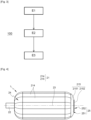
- FIG. 1 An example of implementation of a manufacturing method 200 of a sealed tank according to the invention is illustrated in the form of a flowchart on the Figure 1 .
- the method 200 for manufacturing a sealed tank is preferably used to produce the sealed tank 1 (also referred to as “tank 1” hereinafter) of which an enlargement of a section is shown schematically on the Figure 2 .
- tank 1 is a composite tank suitable for use in the field of transport and delivery of hydrogen under high pressure.
- composite tank designates a type of tank in which the gas-tight function is performed by a thermosetting material and the mechanical pressure resistance function is performed by fiber reinforcements.
- the tank 1 is thus here intended to contain hydrogen maintained under a high pressure, equal to or greater than 700 MPa.
- the tank is furthermore here adapted to contain a liquid such as water.
- the tank 1 may be intended to contain other gases and/or other liquids, under atmospheric storage conditions or under pressures lower than 700 MPa.
- the sealed tank 1 here has a cylindrical interior and exterior shape, according in this example to the same longitudinal axis XX'.
- the exterior shape and the interior shape may have an axis offset from each other, for example parallel to each other.
- the tank 1 comprises a flank on each axial side 1a, 1b, called a front facet which is rounded, dome-shaped or cap-shaped.
- the shape of the tank 1 may be different, for example spherical, ellipsoidal or other shapes.
- the terms “inner”, “outer”, “internal” and “external” are used to denote the position of a part or surface relative to the longitudinal axis XX' of the tank 1, an inner or inner surface (for example) being closer to the longitudinal axis than an outer or external surface.
- the term “axial” means “along the direction of the longitudinal axis” and the terms “radial” and “transverse” mean “along a direction perpendicular to the longitudinal axis”.
- the term “lateral” means “which is located on the sides of a part extending radially”.
- the terms “thickness” and “diameter” denote dimensions measured radially.
- the term “length” denotes a dimension measured axially.
- the tank 1 comprises a wall 11 and an interior volume 13.
- the tank 1 comprises a nozzle 12.
- the internal volume 13 of the tank 1 can have in this example a diameter d 13 of 60 cm and a length l 13 of 3.50 m.
- the end piece 12 of the tank 1 is for example a tap 12 allowing alternately closing/opening the passage of gas or liquid into/out of the tank 1.
- the wall 11 of the tank 1 has a sealed wall 111 and, in this example, a base 112 positioned on one of the axial sides 1b of the tank 1.
- the sealed wall 111 of the wall 11 of the tank 1 has an internal surface 111c which has the shape of the internal volume 13 of the tank 1.
- the sealed wall 111 is formed from a composite material, that is to say it comprises a mixture of at least one thermoplastic material and at least one fibrous material.
- the sealed wall 111 achieves both the internal barrier effect (impermeability) to the gas or liquid contained in the interior volume 13 of the tank 1 and the effect of mechanical resistance to pressure.
- the thermoplastic material(s), as well as the type of fibers of the sealed wall 111 will be described later, in relation to the method 100 for manufacturing the tank 1.
- the base 112 of the wall 11 of the tank 1 is preferably annular in shape, that is to say that it has an internal passage adapted to receive the nozzle (the tap) 12.
- the base 112 advantageously has a curved external surface 112a whose periphery, at least, is positioned in the thickness of the sealed wall 111 (not visible on the Figure 2 ) as explained below.
- the watertight wall 111 and the base 112 forming the tank 1 form a rigid unitary structure capable of withstanding the pressures required by the application.
- the method 200 for manufacturing the tank 1 is described below in relation to the figures 1 to 15 .
- the manufacturing method 100 of the waterproof wall 111 is described below in relation to the figures 3 to 10 .
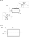
- FIG. 4 illustrates, in schematic form, an example of a mounted mandrel 2, used in the method 100.
- This mandrel 2 is inspired by the document WO2011143723A2 .
- the mandrel 2 acts as an internal mold for the watertight wall 111.
- step E3 of the method 100 implements such a method of filament winding around the mandrel 2.
- the mandrel 2 is here a hollow part of revolution, having an axis of revolution 23.
- the mandrel 2 comprises at one end a removable spindle 22 (or connection) arranged at an axial end of the mandrel 2.
- This spindle 22 of the mandrel 2 is in this example adapted to be coupled to a rotary motor, allowing the mandrel 2 to rotate around its axis of revolution 23.
- the chuck 2 further comprises a removable external surface 21, integral with the spindle 22 (once the assembly of the chuck 2 is complete).
- the external surface 21 of the mandrel 2 has a rounded shape corresponding to the shape (and dimensions) of the internal surface 111c of the sealed wall 111 of the wall 11 of the tank 1 (cf. Figure 2 ).
- the mandrel 2 here has an external surface 21 whose largest diameter is 60 cm and the length 3.50 m.
- the mandrel 2 comprises a plurality of hoops 24 and in this example a bottom 25.
- the bottom 25 comprises in this case a base 251 and a plug 252 positioned in the base 251 but can be formed in a single piece.
- the surface external surface of mandrel 21 comprises each axially elongated external surface 214 of each hoop 24, and an external surface 215 of the bottom 25 arranged opposite the spindle 22 of the mandrel 2.
- the external surface 215 of the bottom 25 comprises in this example an external base surface 2151 and an external cap surface 2152.
- Each hoop 24 is held in position by its opposite ends, one being fixed on the circumference 22a of the spindle 22, and the other being engaged in the base 251 of the bottom 25.
- the hoops 24 can also, according to another example, fit into each other.
- the mounting E1 of the mandrel 2 is carried out, for example, by first coupling the spindle 22 to the rotating tool, then engaging one end of each hoop 24 in the spindle 22, and finally fixing the opposite ends of the hoops 24 with the bottom 25 of the mandrel 2.
- step E2 of the method 100.
- This step E2 aims, as described previously, to form the sealed wall 111 of the wall 11 of the tank 1.
- step E2 begins at sub-step E21.
- a knit 3 is applied to the mandrel 2, covering the external surface 21 of the mandrel 2.
- FIG. 6 represents, in schematic form, a partial view of an example of knitting 3.
- the knit 3 comprises a layer 31 of knitted threads 311, 312 forming loops.
- the knit 3 is thus a structure which can be formed of loops or stitches passed through one another.
- the loops or stitches are formed of “intermingled feet and heads”.
- the knit 3 thus forms a fabric whose stitches can be stretched in various directions having more elasticity than a weave.
- the knitted threads 311, 312 are formed from one or more of the heat-sealed thermoplastic materials of the sealed wall 111 (note that the sealing is not carried out during sub-step E21).
- thermoplastic material(s) of the knit 3 are for example chosen from (but not limited to) thermoplastic materials from the polyolefin family or the polyamide family.
- the knitted threads 311, 312 can thus be made of nylon.
- the diameter of the knitted threads 311, 312 can be between 0.5 mm and 1 mm.
- the knitted yarns 311, 312 preferably form loops oriented in a first direction D1 and a second direction D2 orthogonal to the first direction D1.
- the thickness of the knitted yarns 311, 312 and/or the geometry of the knit are determined so that the mass per surface of the knit 3, once applied to the external surface 21 of the mandrel 2, is between 100 g/m 2 and 800 g/m 2 .
- the knitted threads 311, 312 of the knit 3 form an envelope 30 of knitted threads shaped according to the circumference of the external surface 21 of the mandrel 2.
- the envelope 30 of knitted threads has the shape of the circumference (of the external limits) of the external surface 21 of the mandrel 2 and is placed in contact with this external surface 21.
- the envelope 30 forms a net placed flat, or draping, the external surface 21 of the mandrel 2.
- FIG. 7 represents the mandrel 2 obtained at the end of step E21, this mandrel being, in this case, covered with the envelope 30 of knitted threads.
- the casing 30 does not cover the spindle 22 of the mandrel 22.
- an orifice corresponding to the cross-section of the spindle 22
- orifice 111d for extracting the mandrel 2 thereafter (cf. Figure 10 ), by which the hoops 24, and the bottom 25 of the mandrel 2 can be extracted from inside the sealed wall 111.
- the pin 22 (and therefore the extraction orifice 111d) are therefore sized according to the hoops 24 and the base 25 and the plug 26, so that these can be extracted.
- a portion of the mandrel 2 is not covered by the casing 30 to form the extraction orifice 111d.
- the casing 30 does not cover the external surface 2152 of the plug 252, allowing it to be removed and forms the extraction orifice 111d or a second extraction orifice.
- the pin 22 may be only an internal axis and be covered by 30 and be removed through the extraction orifice 111d when the plug is removed.
- the plug 252 may in this case serve as a support and holding of the mandrel 2, for example by having the axis 23 vertical, during the manufacturing process of the watertight wall.
- the knit 3 is manufactured prior to the execution of the method 100 for manufacturing the sealed tank 1.
- the sleeve is then applied to the mandrel 2, for example by an operator, in the following manner: the sleeve is threaded onto the mandrel 2 by one of the ends of the mandrel 2, in this case by the spindle 22 of the mandrel 2, or by the bottom 212 of the external surface 21 of the mandrel 2.
- the sleeve stretches when being threaded and then, once threaded and released, it retracts onto the external surface of the mandrel. In this way, the knitted fabric 3 is laid flat on the external surface 21 of the mandrel.
- one sleeve can be used to cover the or a part of the external surface 214 of the hoops 24 and another sleeve can be used to cover the external surface 215 of the bottom and optionally one or the other part of the external surface 214 of the hoops 24.
- the sleeves can be applied side by side, or overlap axially.
- the step E21 of applying the knit 3 is particularly quick and easy to perform. For example, it takes, for a trained operator, 10 minutes to form the envelope 30 around the mandrel 2. In other words, a portion of the thermoplastic material(s) of the sealed wall 111 is affixed simply and quickly to the mandrel.
- Another knit may be applied to the knit 3 previously described.
- This knit is denoted “second knit” by the following, while the previously deposited knit is noted “first knit”.
- the envelope 30 is then made up of the two (first and second) superimposed knits. This makes it possible to increase the quantity of thermoplastic material of the envelope 30 of knitted threads. This variant is particularly well suited to increasing the permeability (gas barrier effect) of the sealed wall 111.
- thermoplastic materials have been applied (via the envelope 30) to the external surface 21 of the mandrel 2, it is necessary to provide the other portion of the thermoplastic materials, as well as the fibers necessary to achieve the gas barrier effect. This provision is carried out during sub-step E22 described below, in relation to the figure 8 .
- a filament winding process of the first strip 4 onto the envelope 30 is carried out to cover the envelope 30 with fibers and thermoplastic material.
- the fibers of the first strip 4 are preferably continuous. This makes it possible to obtain a more efficient reinforcement structure and thus to increase the mechanical resistance to pressure of the resulting watertight wall 111.
- the fibers of the first strip 4 are formed from a material chosen from (but not limited to) the following materials: glass, carbon, metal, mineral, wool, cotton, linen, polyester, polypropylene, polyamide, basalt, kevlar ® , stretched thermoplastic or a mixture of two or more of these materials.
- thermoplastic material of this first strip 4 is chemically compatible with the thermoplastic material of the knitted yarns 311, 312.
- chemically compatible means that the thermoplastic materials of the knitted fabric 3 and of the first strip 4 have melting and/or softening points located in identical or similar temperature ranges.
- the heat-sealed thermoplastic material of the first strip 4 may be identical to that of the knitted yarns 311, 312.
- the thermoplastic material of the first strip and that of the knitted yarns may both be from the polyolefin family or from the polyamide family.
- thermoplastic materials of the first strip 4 and the knitted threads 3 will be described later, in relation to sub-step E23.
- the first strip 4 preferably has a width greater than or equal to 20 cm, for example equal to 20 cm, 50 cm or more. This makes it possible to make the execution of substep E22 faster than when the first strip has a smaller width.
- first strip 4 of width less than 20 cm is suitable for the method 100, for example a width of first strip 4 equal to 2 cm, or 4 cm, or even 14 cm is suitable.
- the mandrel 2 is rotated via, in this example, the spindle 22 during the execution of the sub-step E22.
- the mandrel 2 and the casing 30 are stationary and a winder rotates around the mandrel 2 for the filament winding of the first strip 4 onto the casing 30 to cover the casing 30 with fibers and thermoplastic material.
- the strip 4 is, as explained below, wound tightly onto the casing 30, exerting pressure between the strip 4 and the casing 30 during the filament winding at a temperature within a predetermined temperature range so that the strip 4 fuses or unifies with the casing 30.
- the number n1 of superimposed layers of this first strip 4 depends on the diameter and the geometric shape of the mandrel 2 (therefore on the diameter and the shape of the interior volume 13 desired for the tank 1), as well as on the desired burst pressure (i.e. the pressure beyond which the tank 1 no longer holds the pressure and deforms).
- the multilayer winding makes it possible to reduce the permeability and increase the mechanical resistance to pressure of the resulting sealed wall 111 1.
- the sections successive 41 of the first band overlap over a distance between 0 (corresponding to no overlap) and half the width of the first band 4 and according to overlap angles which can vary.
- the heating temperature applied to each section 41 of the first wound strip is determined according to the properties of the thermoplastic material(s) used (in the first strip 4, in the envelope 30 of knitted yarns). Specifically, the temperature is located in the melting range of the thermoplastic materials used (this range being common since the thermoplastic materials are compatible).
- thermoplastic material of each wound section 41 fuses, or unifies, with the underlying yarns of the envelope 30 of knitted yarns.
- thermoplastic material of each wound section 41 fuses, or unifies, with the underlying layer 410i-1 of first strip 4.
- the temperature is chosen to fuse the thermoplastic material of each section of the first layer of first strip with the underlying yarns of the knitted yarn cover, and to fuse the sections of successive layers of first strip.
- the temperature is between 160°C and 340°C.
- the envelope 30 and all of the superimposed layers 40 of the first strip are combined, or consolidated, into a single material.
- a single material is understood here as having such homogeneity that it is impossible, with the naked eye, to distinguish the materials used to produce it.
- the expression “in a single material” designates a monolithic structure which is opposed to a watertight wall which would be made up of two concentric envelopes.
- sub-step E22 is carried out not with a single first strip 4, but with at least one other additional strip, formed from the material of the first strip, the additional strip being wound simultaneously with the first strip 4. This makes it possible to accelerate the execution of this sub-step E22 and thus to make the method 100 for manufacturing the watertight wall 111 faster.
- the method 100 for manufacturing the sealed wall 111 further comprises a sub-step E23 during step E2. During this sub-step E23, cooling of the casing 30 and of all the superimposed layers 40 of the first strip is carried out, to stiffen them. A sealed block 130 is thus obtained, which is the sealed wall 111 of the tank 1. This block 130 is separable from the mandrel 2.
- FIG. 9 illustrates the block 130, and therefore the sealed wall 111, obtained at the end of sub-step E23. It is noted that this block 130 (like the envelope 30 of knitted threads) has the extraction orifice 111d, the latter being positioned at the location of the spindle 22 of the mandrel 2.
- step E3 of the method 100 for manufacturing the watertight wall 111 is implemented after step E2. This step E3 is illustrated in schematic form on the Figure 10 .
- step E3 consists of dismantling the mandrel 2 and extracting it from inside the block 130 through the extraction orifice 111d.
- step E3 the spindle 22 of the chuck 2 is first dismantled, then the hoops 24 are dismantled and removed through the extraction orifice 111d of the block 130 and finally, the bottom 25 is dismantled and also removed through the extraction orifice 111d.
- step E3 the block 130 emptied from the mandrel 2 forms the sealed wall 130, 111 of the tank 1.
- This sealed wall 130, 111 is thus made of a single material (cf. Figure 10 ).
- the watertight wall 130, 111 has, thanks to the consolidation of the envelope 30 of knitted threads with the layers 40 of first wound strip 4, properties of impermeability and mechanical resistance to pressure similar to those of the tank described in the document WO2011143723A2 , while being faster to produce.
- this sub-step E21 is fast (10 minutes are sufficient in the example of tank 1), because the knit 3 is previously manufactured, because it is very quick and easy to apply to the mandrel 2, and, finally, because a single layer 31 of knitted yarns is sufficient to provide the sufficient quantity of thermoplastic material. Indeed, by adapting the knitting parameters, a sufficient knit weight is obtained, allowing the use of a single layer of knitted yarns.
- the unification of the envelope 30 of knitted yarns with the superimposed layers 40 of the first strip makes it possible to produce the waterproof wall 130 in a single material.
- This homogeneous material has several advantages: 1) it increases the resistance to internal pressure of the waterproof wall 130 and 2) increases the impermeability with respect to liquids. This therefore makes it possible to obtain a waterproof wall 130 of better quality and better resistance over time (or, in other words, a longer service life).
- this knit 3 is less than the thickness of a conventional liner.
- the method 200 for manufacturing the tank 1 continues by implementing steps E4 and E5 (cf. Figure 1 ).
- step E4 second step of the manufacturing method 200
- step E4 the base 112 of the wall 11 of the tank 1 (cf. Figure 2 ) is applied against the watertight wall 130, so as to close the extraction orifice 111d.
- the base 112 may be welded against the sealed wall 130, at the periphery of the extraction orifice 111d. In another example, the base 112 may be fitted into the extraction orifice 112.
- the internal passage of the base 112 is of a reduced diameter compared to the diameter of the pin 22.
- this internal passage is advantageously adapted to receive a second pin 6 (cf. Figure 11 ) to allow the watertight wall 130 to rotate around its axis XX'.
- the external periphery 112a of the base 112 may advantageously be formed from a thermoplastic material which can be sealed by heat and is compatible with the material of the sealed wall 130 (i.e. compatible with the thermoplastic material of the knitted threads and therefore compatible with the thermoplastic material of the first strip 4).
- the base 112 may be formed entirely of this thermoplastic material, or only have an overmolding of this material positioned on its outer periphery 112a (in this case, the remainder of the base may be made of metal).
- the overmolded base may be easily welded against the sealed wall 130.
- FIG. 12 represents, in the form of a flowchart, step E5 of the method 200 for manufacturing the sealed tank 1.
- This step E5 aims to reinforce, or consolidate, the sealed wall 130 with a fibrous material to obtain a reinforced sealed wall 150, thus capable of mechanically resisting pressures for example greater than 2 MPa.
- the sealed wall 111 of the tank 1 is, then, the reinforced sealed wall 150.
- this step E5 comprises for this a sub-step E51 comprising a filament winding and a sub-step E52 of cooling the winding.
- sub-step E51 consists of winding successive sections 51 of a second strip 5 of material heat-sealed thermoplastic reinforced with fibers, around the waterproof wall 130.
- thermoplastic material of the second strip 5 is chemically compatible with the thermoplastic material of the first strip 4 and therefore with the thermoplastic material of the knitted threads 311, 312. It is noted that the material of the second strip 5 is thus also compatible with the thermoplastic material of the external periphery 112a or of the external surface of the base 112 (in the case where the latter is formed from a thermoplastic material).
- the second band 5 is similar to the first band 4 in that it can have the same width, the same thickness, or even fibers of the same nature and/or the same weaving geometry.
- the watertight wall 130 can be rotated (for example via the pin 6).
- the process of winding (or reeling) the second strip 5 is similar to that of the first strip 4.
- the axial overlap distance may for example be between 0 (corresponding to no overlap) and half the width of the second strip 5.
- the heating temperature applied to each wound section 51 of the second strip may be identical to the temperature applied when winding the first strip 4.
- the heating temperature applied to each wound section 51 of the second strip is similar, i.e. located in the melting temperature range of the thermoplastic materials used.
- thermoplastic material of each wound section 51 of second strip 5 fuses with the underlying region of the sealing wall 130 and fuses with the underlying layer of second strip (during the formation of the superimposed layers of second strip).
- the superimposed layers 50 of second strip 5 are joined with the waterproof wall 130 to form the waterproof wall 150 reinforced in a single material.
- the second wound strip and the sealed wall 130 are cooled and therefore stiffened so that the reinforced sealed wall 150 is consolidated and rigid.
- the reinforced sealed wall 150 then forms the sealed wall 111 of the tank 1.
- Cooling can be carried out after sub-step E51, i.e. once the winding of the second strip 5 is complete.
- cooling can be carried out locally, during winding E51 of the second strip 5.
- Cooling E52 can be carried out in a controlled manner by injecting cooled water into the sealed wall 130, and/or by applying pressure to the internal surface of the sealed wall 130.
- sub-step E511 consists of winding the successive sections 51 of the second strip 5 not only around the sealed wall 111 but also on the external surface 112a of the base 112.
- the superimposed layers 50 of second strip 5 thus also cover the external periphery 112a of the base 112.
- the outer periphery 112a of the base When the outer periphery 112a of the base is covered with the thermoplastic material compatible with the thermoplastic material of the sealed wall 111, the superimposed layers 50 of the second strip 5 are joined with the sealed wall 111 and with the outer periphery 112a of the base 112.
- the reinforced sealed wall 150 (and therefore the sealed wall 111 of the tank 1) is thus extended to the circumference of the pin 6 and formed from a single material.
- the reinforced watertight wall 150 (and therefore the watertight wall 111 of the tank 1) extends to the periphery of the internal passage of the base 112.
- the base 112 is partially integrated into the thickness of the watertight wall 111. This makes it possible to avoid breaks in pressure resistance around the tap of the tank 1 and thus to obtain a tank 1 which is watertight and mechanically resistant to the pressures involved.
- the sealed wall 111 of the tank 1 obtained by implementing the sub-step E511 is advantageously more homogeneous than that obtained according to the first embodiment E51. Indeed, this sealed wall 111 is then formed along its entire periphery from the same reinforced material. This makes it possible to obtain a tank 1 having impermeability properties, and identical mechanical properties at every point of its sealed wall 111. This (spatial) homogeneity of the sealed wall 111 makes it possible to produce a tank 1 of better quality.
- the method 100 may comprise, after step E5, a step (not shown in the figures) consisting of applying the tap 122 of the nozzle 12 of the reservoir 1 in the internal passage of the base 112.
- the reservoir 1 illustrated in the Figure 2 is then obtained.
Landscapes
- Engineering & Computer Science (AREA)
- Mechanical Engineering (AREA)
- Chemical & Material Sciences (AREA)
- Composite Materials (AREA)
- General Engineering & Computer Science (AREA)
- Textile Engineering (AREA)
- Manufacturing & Machinery (AREA)
- Moulding By Coating Moulds (AREA)
- Filling Or Discharging Of Gas Storage Vessels (AREA)
- Moulds For Moulding Plastics Or The Like (AREA)
- Laminated Bodies (AREA)
Abstract
Un aspect de l'invention concerne un procédé de fabrication d'un réservoir étanche pour contenir un gaz et/ou un liquide, comprenant un étape de formation d'une paroi étanche du réservoir, comprenant les sous-étapes suivantes :
- Formation d'une enveloppe par application d'au moins un tricot recouvrant la surface externe du mandrinle tricot comprenant des fils tricotés d'un matériau thermoplastique colmatable par chaleur,
- Enroulement filamentaire, autour de l'enveloppe, de sections successives d'une première bande comprenant un matériau thermoplastique colmatable par chaleur renforcé de fibres, de manière à fusionner les sections successives bobinées de la première bande,
- Refroidissement de l'enveloppe et de la première bande pour former la paroi étanche en une seule matière.
- Formation d'une enveloppe par application d'au moins un tricot recouvrant la surface externe du mandrinle tricot comprenant des fils tricotés d'un matériau thermoplastique colmatable par chaleur,
- Enroulement filamentaire, autour de l'enveloppe, de sections successives d'une première bande comprenant un matériau thermoplastique colmatable par chaleur renforcé de fibres, de manière à fusionner les sections successives bobinées de la première bande,
- Refroidissement de l'enveloppe et de la première bande pour former la paroi étanche en une seule matière.
Description
- Le domaine technique de l'invention concerne les procédés de fabrication de réservoirs étanches, ou récipients étanches, notamment mais non limitativement les réservoirs sous pression en matériau composite.
- La présente invention concerne un procédé de fabrication d'un réservoir étanche utilisant des matériaux thermoplastiques renforcés par des fibres dans le processus de fabrication.
- Les conditions de stockage de gaz ou de liquide se sont récemment améliorées avec l'apparition des réservoirs étanches composites qui comprennent un matériau fibreux, c'est-à-dire qui est renforcé par des fibres, comme structure de paroi, ou enveloppe externe.
- Par « réservoir étanche », on entend un réservoir ou récipient étanche aux liquides et/ou aux gaz. Plus précisément, on entend un réservoir qui présente, pour ces liquides et/ou ces gaz, une perméabilité inférieure à une limite maximale prescrite par l'application.
- Par exemple, un réservoir étanche destiné à une application de transport d'hydrogène sous forme comprimée à haute pression présente une perméabilité à l'hydrogène lorsque ce gaz est comprimé dans une gamme de pressions allant de 30 MPa à 70 MPa (soit de 300 bars à 700 bars).
- Il est connu, pour permettre le stockage de l'hydrogène dans ces conditions de pression, d'utiliser une architecture de réservoir étanche dite de type III ou IV. Cette architecture comporte, de l'intérieur vers l'extérieur, une bouteille étanche, aussi appelée « liner interne » selon la terminologie couramment employée, et une structure externe de renfort réalisée par enroulement filamentaire.
- Le rôle du liner interne est principalement d'assurer une fonction d'étanchéité au gaz (il doit être le plus imperméable possible à l'hydrogène). Le rôle de la structure externe de renfort est principalement d'assurer une fonction de résistance mécanique à la pression.
- Dans les réservoirs de type III, le liner interne est métallique. Dans les réservoirs de type IV, le liner interne est en polymère et réalisé par roto-moulage ou par extrusion-soufflage par exemple.
- Un nouveau type de réservoir est décrit dans le document
WO2011143723A2 . L'étanchéité au gaz y est réalisée autrement que par un liner interne métallique. Le liner est ainsi remplacé par une enveloppe interne étanche formée en bobinant et en chauffant une bande de revêtement formée d'un matériau thermoplastique colmatable par chaleur autour d'un gabarit (ou mandrin). Ce gabarit est métallique, démontable en de multiple arceaux s'emboitant de façon circonférentielle les uns aux autres, permettant d'être amovible et réutilisable. Le gabarit présente de plus une forme qui correspond à la forme du réservoir. Typiquement, le gabarit présente une forme cylindrique et, de chaque côté axial, une facette frontale arrondie, en forme de calotte. - Afin d'assurer la solidité mécanique et pour consolider la barrière aux gaz, l'enveloppe interne étanche est protégée par une deuxième enveloppe, appelée enveloppe externe protectrice, faite aussi à partir d'une bande bobinée, comprenant un matériau thermoplastique colmatable par chaleur et renforcé de fibres qui sont de préférence continues. Cette deuxième enveloppe constitue la structure externe de renfort du réservoir étanche.
- Cette enveloppe externe est, comme l'enveloppe interne, formée en bobinant une bande de revêtement sur la première enveloppe (qui joue alors le rôle de mandrin), le matériau de la bande de revêtement bobiné étant le matériau thermoplastique renforcé par les fibres. La paroi étanche résultante du réservoir étanche comprend ainsi deux constituants (l'enveloppe interne, l'enveloppe externe).
- Comme l'enveloppe interne étanche faite à partir de la bande bobinée de matériau thermoplastique est beaucoup plus légère et, aussi, moins coûteuse qu'un liner (métallique mais aussi en polymère), son utilisation permet d'alléger considérablement la masse du réservoir et de diminuer son coût.
- Cet avantage est toutefois pondéré par l'augmentation du temps de fabrication du réservoir étanche, puisque le bobinage de la bande de revêtement lors de la fabrication de l'enveloppe interne étanche prend beaucoup de temps. En effet la bande de revêtement, étant étroite et peu épaisse en comparaison des dimensions du gabarit et de l'épaisseur souhaitée de l'enveloppe interne étanche, doit être bobinée par de multiples tours autour du gabarit. Précisément, la bande de revêtement est bobinée pour former une pluralité de spires superposées se chevauchant longitudinalement et radialement, formant ainsi plusieurs couches autour du gabarit. De plus, la vitesse de bobinage est contrainte par l'étirement et la pression à appliquer à la bande de revêtement pour que la première couche soit bien serrée sur le gabarit et que les couches successives soient serrées entre elles. Cela permet d'éviter des bulles d'air entre chaque spire et couche lors de l'étape de chauffage qui permet de fusionner ou de ramollir les spires entre elles afin de les consolider.
- Par exemple, il faut plusieurs heures pour bobiner une bande de 120 µm à 150 µm d'épaisseur et de 25 mm à 80 mm de largeur autour d'un gabarit cylindrique de 60 cm de diamètre et de 3,50 m de longueur, sur une épaisseur comprise entre 2 mm et 5 mm. Une telle durée entrave le déploiement du procédé de fabrication à l'échelle industrielle.
- Il existe donc un besoin d'accélérer la fabrication d'un réservoir étanche, en particulier d'un réservoir étanche ne comportant pas de liner interne.
- L'invention offre une solution aux problèmes évoqués précédemment, en permettant d'obtenir une paroi étanche en une seule étape de bobinage d'un matériau fibré.
- Un premier aspect de l'invention concerne un procédé de fabrication d'une paroi étanche d'un réservoir étanche, le réservoir étanche étant adapté pour contenir un gaz et/ou un liquide, le procédé de fabrication comprenant les étapes suivantes :
- Monter un mandrin réutilisable et amovible par montage/démontage d'arceaux, le mandrin présentant une surface externe de forme correspondant à une surface interne de la paroi étanche du réservoir,
- Former la paroi étanche du réservoir sur la surface externe du mandrin, en formant un orifice d'extraction du mandrin,
- Retirer le mandrin hors de la paroi étanche par l'orifice d'extraction,
- Formation d'une enveloppe par application d'au moins un tricot recouvrant la surface externe du mandrin, le tricot comportant une couche de fils tricotés formant des boucles, les fils tricotés étant d'un matériau thermoplastique colmatable par apport de chaleur,
- Bobinage, autour de l'enveloppe formée par le tricot recouvrant la surface externe du mandrin, de sections successives d'une première bande comprenant un matériau thermoplastique colmatable par apport de chaleur et renforcé de fibres, de sorte que les sections successives de première bande bobinées se recouvrent pour former une première couche de première bande et se recouvrent pour former des couches superposées de première bande, le bobinage étant effectué en :
- Exerçant une pression choisie pour serrer chaque section de la première bande bobinée contre l'enveloppe, formant la première couche de première bande, et pour serrer les sections recouvrant la première couche de première bande pour former les autres couches superposées de première bande, et en
- Exerçant une température choisie pour fusionner le matériau thermoplastique de chaque section de la première couche de première bande avec les fils sous-jacents de l'enveloppe, et pour fusionner les sections des couches successives de première bande,
- Refroidissement de l'enveloppe et de la première bande bobinée pour former la paroi étanche en une seule matière.
- Ainsi, l'utilisation liminaire d'un tricot dont les fils/boucles sont d'un matériau thermoplastique compatible avec le matériau thermoplastique de la première bande (les deux constituants fusionnent sous l'effet combiné de la pression et de la température exercée pendant le bobinage) permet avantageusement de s'affranchir d'une étape, très consommatrice en temps, de bobinage d'une bande de matériau thermoplastique autour du mandrin. Le procédé de fabrication de la paroi étanche d'un réservoir étanche est ainsi plus rapide que la solution proposée par le document de l'art antérieur.
- En effet, un seul tricot (ou une seule couche de fils tricotés) apporte suffisamment de matière thermoplastique pour créer, en fusionnant avec la première bande, un effet barrière au gaz de même tenue mécanique à la pression que l'enveloppe interne étanche du réservoir selon l'art antérieur. Comme le tricot est fabriqué au préalable, il n'a pas à être formé pendant le processus de fabrication du réservoir, contrairement à l'enveloppe interne étanche du réservoir selon l'art antérieur. Le tricot est en outre aisé et rapide à appliquer sur le mandrin puisqu'il peut y être simplement enfilé, par exemple manuellement.
- De plus, grâce aux fils/boucles du tricot qui sont d'un matériau thermoplastique compatible avec le matériau thermoplastique de la première bande, la paroi étanche obtenue est monolithique, c'est-à-dire formée d'une seule matière. Dit autrement, on ne peut pas, une fois le bobinage par la première bande achevé, distinguer les constituants utilisés (les fils tricotés et le matériau thermoplastique imprégnant les fibres de renfort). Cette homogénéité de la paroi étanche permet, par rapport à une paroi étanche composée de deux enveloppes interne et externe (telles que celles présentes dans les solutions de l'art antérieur), d'améliorer la robustesse du réservoir.
- Précisément, la paroi étanche du réservoir monolithique résiste mieux qu'une paroi à double couche lorsqu'un vide ou une dépressurisation sont appliquées à l'intérieur du réservoir étanche. Comme ces conditions de pression et de température sont celles rencontrées lors des phases de séchage et décontamination du réservoir, ou lors des phases de vidange, le réservoir étanche obtenu est mieux adapté à son usage et présente une durée de vie plus longue.
- Outre les caractéristiques qui viennent d'être évoquées dans les paragraphes précédents, le procédé selon le premier aspect de l'invention peut présenter une ou plusieurs caractéristiques complémentaires parmi les suivantes, considérées individuellement ou selon toutes les combinaisons techniquement possibles.
- le matériau thermoplastique des fils tricotés est identique au matériau thermoplastique de la première bande.
- le tricot présente une masse par surface comprise entre 100 g/m2 et 800 g/m2.
- le tricot se présente sous la forme d'un ou plusieurs manchons, chaque manchon étant enfilé par une extrémité du mandrin.
- la sous-étape de formation de l'enveloppe comprend en outre l'application d'un deuxième tricot sur le premier tricot, le matériau thermoplastique des fils tricotés du deuxième tricot étant colmatable par apport de chaleur dans les mêmes conditions de température et de pression que le matériau thermoplastique des fils tricotés du premier tricot sous-jacent.
- la sous étape de bobinage autour de l'enveloppe comprend le bobinage d'au moins une autre bande additionnelle, formée du matériau de la première bande, la bande additionnelle étant bobinée simultanément avec la première bande.
- Un deuxième aspect de l'invention concerne un procédé de réalisation d'une paroi étanche renforcée d'un réservoir comprenant les étapes du procédé de la paroi étanche décrite précédemment avec ou sans les différents modes de mise en oeuvre, comprenant les sous-étapes suivantes :
- Bobinage, autour de la paroi étanche, de sections successives d'une deuxième bande comprenant un matériau thermoplastique colmatable par chaleur renforcé de fibres, de sorte que les sections successives de deuxième bande bobinées se recouvrent pour former une première couche de deuxième bande et se recouvre pour former des couches superposées de deuxième bande, le bobinage étant effectué en :
- Exerçant une pression choisie pour serrer chaque section de la deuxième bande bobinée contre la paroi étanche, formant la première couche de deuxième bande, et pour serrer les sections recouvrant la première couche de deuxième bande pour former les autres couches superposées de deuxième bande, et en
- Exerçant une température choisie pour fusionner le matériau thermoplastique de chaque section de la première couche de deuxième bande avec la région sous-jacente de la paroi étanche, et pour fusionner les sections des couches successives de deuxième bande,
- Refroidissement de la paroi étanche et de la deuxième bande pour former la paroi étanche renforcée en une seule matière.
- Ainsi, la paroi étanche du réservoir est renforcée en fibres et en matériaux thermoplastique. Cela permet d'augmenter l'étanchéité et la résistance mécanique à la pression du réservoir.
- Avantageusement, le matériau thermoplastique des fils tricotés du tricot est identique au matériau thermoplastique de la première bande.
- Ainsi, l'enveloppe et la deuxième bande bobinée sont unifiées de la manière la plus parfaite possible.
- Un troisième aspect de l'invention concerne un procédé de fabrication d'un réservoir étanche pour contenir un gaz ou un liquide, comprenant les étapes suivantes
- Fabriquer une paroi étanche du réservoir en accomplissant les étapes du procédé de fabrication selon le premier aspect de l'invention, avec ou sans les différents modes de réalisation décrits précédemment,
- Fermer la paroi étanche en appliquant une embase contre la paroi étanche,
- Consolider la paroi étanche pour obtenir une paroi étanche renforcée du réservoir,
- Bobinage, autour la paroi étanche, de sections successives d'une deuxième bande comprenant un matériau thermoplastique colmatable par chaleur renforcé de fibres, de sorte que les sections successives de deuxième bande bobinées se recouvrent pour former une première couche de deuxième bande et se recouvrent pour former des couches superposées de deuxième bande, le bobinage étant effectué en :
- Exerçant une pression choisie pour serrer chaque section de la deuxième bande bobinée contre la paroi étanche, formant la première couche de deuxième bande, et pour serrer les sections recouvrant la première couche de deuxième bande pour former les autres couches superposées de deuxième bande, et en
- Exerçant une température choisie pour fusionner le matériau thermoplastique de chaque section de la première couche de deuxième bande avec la région sous-jacente de la paroi étanche, et pour fusionner les sections des couches successives de deuxième bande,
- Refroidissement de la paroi étanche et de la deuxième bande pour former la paroi étanche renforcée en une seule matière.
- Le matériau thermoplastique de la deuxième bande est donc chimiquement compatible avec la région sous-jacente de la paroi étanche pour fusionner ensemble.
- Selon un mode de réalisation, les matériaux thermoplastiques de la première et de la deuxième bande sont identiques.
- Selon un mode de réalisation, l'embase présente une surface périphérique externe recouverte d'un matériau thermoplastique colmatable par chaleur et compatible avec le matériau thermoplastique de la paroi étanche. Selon un exemple, la surface périphérique de l'embase est chauffée avant l'étape de fermeture pour fusionner avec une surface périphérique interne de la paroi étanche définissant l'orifice d'extraction pendant l'étape de fermeture de la paroi étanche.
- Selon un mode de réalisation, la surface externe de l'embase est recouverte par la deuxième bande lors de ladite étape de consolidation de la paroi étanche.
- L'invention et ses différentes applications seront mieux comprises à la lecture de la description qui suit et à l'examen des figures qui l'accompagnent.
- Les figures sont présentées à titre indicatif et nullement limitatif de l'invention.
- La
figure 1 représente, sous forme de logigramme, les principales étapes d'un procédé de fabrication d'un réservoir étanche selon un aspect de l'invention ; - La
figure 2 est une représentation schématique en vue de coupe d'un réservoir étanche obtenu selon le procédé de fabrication représenté sur lafigure 1 ; - La
figure 3 représente, sous forme de logigramme, les principales étapes du procédé de fabrication d'une paroi étanche, première étape du procédé de fabrication représenté sur lafigure 1 ; - La
figure 4 représente, sous forme schématique, un exemple de mandrin mis en oeuvre lors du procédé de fabrication représenté sur lafigure 3 ; - La
figure 5 représente, sous forme de logigramme, la deuxième étape du procédé de fabrication représenté sur lafigure 3 , - La
figure 6 représente, sous forme schématique, un exemple de tricot mis en oeuvre lors l'étape représentée sur lafigure 5 ; - La
figure 7 représente, sous forme schématique, une paroi étanche semi finie en cours de fabrication lors de la première sous-étape de l'étape représentée sur lafigure 5 ; - La
figure 8 représente, sous forme schématique, la deuxième sous-étape de l'étape représentée sur lafigure 5 ; - La
figure 9 représente, sous forme schématique, un bloc formant la paroi étanche entourant un mandrin lors de la troisième sous-étape de l'étape représentée sur lafigure 5 ; - La
figure 10 représente, sous forme schématique, une paroi étanche obtenue après la troisième étape du procédé de fabrication représenté sur lafigure 3 ; - La
figure 11 représente, sous forme schématique, un réservoir semi fini lors de la deuxième étape du procédé de fabrication représenté sur lafigure 1 ; - La
figure 12 représente, sous forme de logigramme, des sous-étapes de la troisième étape du procédé de fabrication représenté enfigure 1 , - La
figure 13 représente, sous forme schématique, la première sous-étape de l'étape représentée sur lafigure 11 ; - La
figure 14 représente, sous forme schématique, une sous-étape alternative à la première sous-étape représentée sur lafigure 13 ; - La
figure 15 représente, sous forme schématique, un réservoir obtenu après la deuxième sous-étape de l'étape représentée sur lafigure 12 . - Sauf précision contraire, un même élément apparaissant sur des figures différentes présente une référence unique.
- La présente invention se place dans le contexte des réservoirs étanches et de leurs procédés de fabrication. Plus particulièrement, l'invention vise à produire de manière plus rapide des réservoirs étanches présentant une résistance à la pression supérieure à 0,2 MPa et des caractéristiques de barrière au gaz (imperméabilité au gaz/ou au liquide à contenir dans le réservoir étanche) similaires, voire meilleures, que celles des solutions de l'art antérieur.
- Un exemple de mise en oeuvre d'un procédé de fabrication 200 d'un réservoir étanche conforme à l'invention est illustré sous forme de logigramme sur la
figure 1 . - Le procédé 200 de fabrication d'un réservoir étanche est préférentiellement utilisé pour produire le réservoir étanche 1 (aussi noté « réservoir 1 » par la suite) dont un agrandissement d'une coupe est représenté schématiquement sur la
figure 2 . - En particulier, le réservoir 1 est un réservoir composite adapté à un usage dans le domaine du transport et de la livraison d'hydrogène sous haute pression.
- L'expression « réservoir composite » désigne un type de réservoir dans lequel la fonction d'étanchéité au gaz est réalisée par un matériau thermodurcissable et la fonction de résistance mécanique à la pression est réalisée par des renforts fibrés. Le réservoir 1 est ainsi ici destiné à contenir de l'hydrogène maintenu sous une pression élevée, égale ou supérieure à 700 MPa. Le réservoir est en outre ici adapté à contenir un liquide tel que de l'eau. Naturellement, dans d'autres exemples, le réservoir 1 peut être destiné à contenir d'autres gaz et/ou d'autres liquides, dans des conditions de stockage atmosphériques ou sous des pressions inférieures à 700 MPa.
- Comme le montre la
figure 2 , le réservoir étanche 1 présente ici une forme intérieure et extérieure cylindrique, selon dans cet exemple un même axe longitudinal XX'. La forme extérieure et la forme intérieure peuvent avoir un axe décalé l'un par rapport à l'autre par exemple parallèle l'un à l'autre. Le réservoir 1 comprend un flanc de chaque côté axial 1a, 1b, appelée facette frontale qui est arrondie, en forme de dôme ou de calotte. Dans d'autres exemples, la forme du réservoir 1 peut être différente, par exemple sphérique, ellipsoïdale ou d'autres formes. - Dans la description qui suit, les termes « intérieur », « extérieur », « interne » et « externe » sont utilisés pour désigner la position d'une pièce ou d'une surface par rapport à l'axe longitudinal XX' du réservoir 1, une surface intérieure ou interne (par exemple) étant plus proche de l'axe longitudinal qu'une surface extérieure ou externe. Le terme « axial » signifie « suivant la direction de l'axe longitudinal » et les termes « radial » et « transversal » signifient « suivant une direction perpendiculaire à l'axe longitudinal ». Le terme « latéral » signifie « qui est situé sur les côtés d'une pièce s'étendant radialement ». Les termes « épaisseur » et « diamètre » désignent des dimensions mesurées radialement. Le terme « longueur » désigne une dimension mesurée axialement.
- Plus précisément, et toujours en référence à la
figure 2 , le réservoir 1 comporte une paroi 11 et un volume intérieur 13. Dans cet exemple le réservoir 1 comprend un embout 12. - Le volume intérieur 13 du réservoir 1 peut présenter dans cet exemple un diamètre d13 de 60 cm et une longueur l13 de 3,50 m.
- L'embout 12 du réservoir 1 est par exemple un robinet 12 permettant alternativement de fermer/ouvrir le passage du gaz ou du liquide dans/hors du réservoir 1.
- La paroi 11 du réservoir 1 présente une paroi étanche 111 et, dans cet exemple, une embase 112 positionnée sur l'un des côtés axiaux 1b du réservoir 1.
- La paroi étanche 111 de la paroi 11 du réservoir 1 présente une surface interne 111c qui a la forme du volume intérieur 13 du réservoir 1.
- La paroi étanche 111 est formée d'un matériau composite, c'est-à-dire qu'elle comprend, un mélange d'au moins un matériau thermoplastique et au moins un matériau fibreux. La paroi étanche 111 réalise à la fois l'effet barrière interne (l'imperméabilité) au gaz ou au liquide contenu dans le volume intérieur 13 du réservoir 1 et l'effet de résistance mécanique à la pression. Le ou les matériaux thermoplastiques, ainsi que le type de fibres de la paroi étanche 111 seront décrits ultérieurement, en relation avec le procédé 100 de fabrication du réservoir 1.
- L'embase 112 de la paroi 11 du réservoir 1 est de préférence de forme annulaire, c'est-à-dire qu'elle présente un passage intérieur adapté à recevoir l'embout (le robinet) 12.
- Dans l'exemple du réservoir 1 illustré sur la
figure 2 , l'embase 112 présente avantageusement une surface externe courbée 112a dont la périphérie, au moins, est positionnée dans l'épaisseur de la paroi étanche 111 (non visibles sur lafigure 2 ) comme expliquée dans la suite. Ainsi, la paroi étanche 111 et l'embase 112 formant le réservoir 1, forment une structure rigide unitaire capable de résister aux pressions exigées par l'application. - Le procédé 200 de fabrication du réservoir 1 est décrit ci-après en relation avec les
figures 1 à 15 . - Comme le montre la
figure 1 , le procédé 200 de fabrication du réservoir 1 comprend les étapes successives suivantes : - Fabriquer la paroi étanche 111 de la paroi 11 du réservoir 1 selon un procédé de fabrication noté 100 conforme à un autre aspect de l'invention,
- Fermer E4 la paroi étanche 111 en appliquant l'embase contre la paroi étanche.
- En outre optionnellement le procédé 200 comprend en outre une étape suivante :
- Consolider E5 la paroi étanche 111 pour obtenir une paroi étanche renforcée.
- Le procédé de fabrication 100 de la paroi étanche 111 est décrit ci-après en relation avec les
figures 3 à 10 . - En référence à la
figure 3 , le procédé 100 de fabrication de la paroi étanche 111 comprend les étapes suivantes : - Monter E1 un mandrin 2 réutilisable et amovible par montage/démontage d'arceaux 24, le mandrin 2 présentant une surface externe de forme correspondant à la surface interne 111c de la paroi étanche 111 de la paroi 11 du réservoir 1,
- Former E2 la paroi étanche 111 de la paroi 11 du réservoir 1 sur la surface externe du mandrin 2, en formant un orifice d'extraction 111d du mandrin 2,
- Retirer E3 le mandrin 2 hors de la paroi étanche 111 par l'orifice d'extraction 111d.
- La
figure 4 illustre, sous forme schématique, un exemple de mandrin 2 monté, utilisé dans le procédé 100. Ce mandrin 2 est inspiré du documentWO2011143723A2 . - Le mandrin 2 joue le rôle d'un moule intérieur de la paroi étanche 111.
- Le mandrin 2 convient à l'enroulement filamentaire. En effet, comme il sera décrit plus loin, l'étape E3 du procédé 100 met en oeuvre un tel procédé d'enroulement filamentaire autour du mandrin 2.
- Comme le montre la
figure 4 , le mandrin 2 est ici une pièce de révolution creuse, présentant un axe de révolution 23. - Le mandrin 2 comporte dans cet exemple à une extrémité une broche 22 amovible (ou raccord) disposée à une extrémité axiale du mandrin 2. Cette broche 22 du mandrin 2 est dans cet exemple adaptée pour être couplée à un moteur rotatif, permettant de mettre en rotation le mandrin 2 autour de son axe de révolution 23.
- Le mandrin 2 comporte en outre une surface externe 21 amovible, solidaire de la broche 22 (une fois le montage du mandrin 2 achevé).
- La surface externe 21 du mandrin 2 présente une forme arrondie correspondant à la forme (et aux dimensions) de la surface intérieure 111c de la paroi étanche 111 de la paroi 11 du réservoir 1 (cf.
figure 2 ). Ainsi, selon l'exemple du réservoir 1 détaillé précédemment, le mandrin 2 présente ici une surface externe 21 dont le plus grand diamètre est 60 cm et la longueur 3,50 m. - Le mandrin 2 comprend une pluralité d'arceaux 24 et dans cet exemple un fond 25. Le fond 25 comprend en l'occurrence une embase 251 et un bouchon 252 positionné dans l'embase 251 mais peut être formé en une seule pièce. La surface externe de mandrin 21 comprend chaque surface externe 214 allongé axialement de chaque arceau 24, et une surface externe 215 du fond 25 disposé à l'opposé de la broche 22 du mandrin 2. La surface externe 215 du fond 25 comprend dans cet exemple une surface externe d'embase 2151 et une surface externe de bouchon 2152. Chaque arceau24 est maintenu en position par ses extrémités opposées, l'une étant fixé sur la circonférence 22a de la broche 22, et l'autre étant engagée dans l'embase 251 du fond 25. Les arceaux 24 peuvent aussi selon un autre exemple s'emboiter les uns dans les autres.
- Le montage E1 du mandrin 2 s'effectue, par exemple, en couplant d'abord la broche 22 sur l'outillage rotatif, puis en engageant une extrémité de chaque arceau 24 dans la broche 22, et enfin en fixant les extrémités opposées des arceaux 24 avec le fond 25 du mandrin 2.
- Naturellement, d'autres configurations du mandrin 2 sont possibles (non représentées par les figures).
- La
figure 5 représente, sous forme de logigramme, l'étape E2 du procédé 100. Cette étape E2 vise, comme décrit précédemment, à former la paroi étanche 111 de la paroi 11 du réservoir 1. - Comme le montre la
figure 5 , l'étape E2 débute à la sous-étape E21. Lors de cette sous-étape E21, un tricot 3 est appliqué sur le mandrin 2, en recouvrant la surface externe 21 du mandrin 2. - La
figure 6 représente, sous forme schématique, une vue partielle d'un exemple de tricot 3. - Comme le montre la
figure 6 , le tricot 3 comprend une couche 31 de fils tricotés 311,312 formant des boucles. Le tricot 3 est ainsi une structure qui peut être formée de boucles ou mailles passées les unes dans les autres. Par exemple les boucles ou mailles sont formées de « pieds et têtes entremêlés ». Le tricot 3 forme ainsi une étoffe dont les mailles peuvent être étirées dans diverses directions ayant plus d'élasticité qu'un tissage. - Les fils tricotés 311, 312 sont formés du ou de l'un des matériaux thermoplastiques colmatable par chaleur de la paroi étanche 111 (notons que le colmatage n'est pas effectué lors de la sous-étape E21).
- Le ou les matériaux thermoplastiques du tricot 3 sont par exemple choisis parmi (mais non limités aux) matériaux thermoplastiques de la famille des polyoléfines ou de la famille des polyamides.
- Les fils tricotés 311,312 peuvent ainsi être en nylon. Dans ce cas notamment, le diamètre des fils tricotés 311, 312 peut être compris entre 0,5 mm et 1 mm.
- Les fils tricotés 311, 312 forment préférentiellement des boucles orientées suivant une première direction D1 et une deuxième direction D2 orthogonales à la première direction D1. L'épaisseur des fils tricotés 311, 312 et/ou la géométrie du tricot, sont déterminées pour que la masse par surface du tricot 3, une fois appliqué sur la surface externe 21 du mandrin 2, soit comprise entre 100 g/m2 et 800 g/m2.
- Ainsi, à l'issue de la sous-étape E21, les fils tricotés 311, 312 du tricot 3 forment une enveloppe 30 de fils tricotés conformée selon le pourtour de la surface externe 21 du mandrin 2. Autrement dit, l'enveloppe 30 de fils tricotés présente la forme de la circonférence (des limites extérieures) de la surface externe 21 du mandrin 2 et est posée au contact de cette surface externe 21. Dit autrement encore, l'enveloppe 30 forme un filet posé à plat, ou drapant, la surface externe 21 du mandrin 2.
- Cette enveloppe 30 de fils tricotés fournit une première partie du ou des matériaux thermoplastiques de la paroi étanche 111. Comme décrit précédemment, ce ou ces matériaux thermoplastiques sont nécessaires pour réaliser l'effet barrière (l'imperméabilité) au gaz ou au liquide à contenir dans le volume intérieur 13 du réservoir 1.
- La
figure 7 représente le mandrin 2 obtenu à l'issue de l'étape E21, ce mandrin étant, en l'occurrence, recouvert de l'enveloppe 30 de fils tricotés. - Comme on le voit sur la
figure 7 , l'enveloppe 30 ne recouvre pas la broche 22 du mandrin 22. Ainsi, lorsque la broche 22 sera retirée, lors de l'étape E3 du procédé 100, il subsistera un orifice (correspondant à la section transversale de la broche 22), noté « orifice 111d d'extraction du mandrin 2 » par la suite (cf.figure 10 ), par lequel les arceaux 24, et le fond 25 du mandrin 2 pourront être extraits depuis l'intérieur de la paroi étanche 111. La broche 22 (et donc l'orifice d'extraction 111d) sont pour cela dimensionnés en fonction des arceaux 24 et de l'embase 25 et le bouchon 26, pour que ceux-ci puissent être extraits. - En tout état de cause, une partie du mandrin 2 n'est pas recouvert par l'enveloppe 30 pour former l'orifice d'extraction 111d. Selon un autre exemple non représenté, l'enveloppe 30 ne recouvre pas la surface externe 2152 du bouchon 252, permettant de le retirer et forme l'orifice d'extraction 111d ou un deuxième orifice d'extraction. Dans cet exemple, la broche 22 peut être uniquement un axe interne et être recouvert par 30 et être retiré par l'orifice d'extraction 111d lorsque le bouchon est retiré. Le bouchon 252 peut dans ce cas servir de support et maintien du mandrin 2, par exemple en ayant l'axe 23 vertical, pendant le procédé de fabrication de la paroi étanche.
- En pratique, le tricot 3 est fabriqué préalablement à l'exécution du procédé 100 de fabrication du réservoir étanche 1.
- Il se présente avantageusement sous la forme d'un ou plusieurs manchons (ou chaussettes) (non représentés par les figures). Ces manchons sont étirables et rétractables, du fait qu'ils ne sont faits que des fils 311,312 tricotés.
- Le manchon est alors appliqué sur le mandrin 2, par exemple par un opérateur, de la manière suivante : le manchon est enfilé sur le mandrin 2 par l'une des extrémités du mandrin 2, en l'occurrence par la broche 22 du mandrin 2, ou par le fond 212 de la surface externe 21 du mandrin 2. Le manchon s'étire au moment d'être enfilé puis, une fois enfilé et relâché, il se rétracte sur la surface externe du mandrin. De la sorte, le tricot 3 est déposé à plat sur la surface externe 21 du mandrin.
- Plusieurs manchons sont avantageusement utilisés lorsque les dimensions du mandrin sont grandes (par exemple lorsque sa longueur est supérieure à 1 m).
- Dans d'autres cas, on utilise plusieurs manchons spécifiquement adaptés pour se conformer aux différentes formes (diamètres) de la surface externe 21 du mandrin 2. Ainsi, un manchon peut être utilisé pour recouvrir la ou une partie de la surface externe 214 des arceaux 24 et un autre manchon peut être utilisé pour recouvrir la surface externe 215 du fond et optionnellement une ou l'autre partie de la surface externe 214 des arceaux 24. Les manchons peuvent être appliqués côte à côte, ou se chevaucher axialement.
- En tout état de cause, quel que soit le nombre de manchons, et quelle que soit la dimension du mandrin (en particulier sa longueur), l'étape E21 d'application du tricot 3 est particulièrement rapide et aisée à exécuter. Par exemple, il faut, pour un opérateur formé, 10 minutes pour former l'enveloppe 30 autour du mandrin 2. Dit autrement, une partie du ou des matériaux thermoplastiques de la paroi étanche 111 est apposée de manière simple et rapide sur le mandrin.
- En variante, un autre tricot (non représenté par les figures) peut être appliqué sur le tricot 3 précédemment décrit. Ce tricot est noté « deuxième tricot » par la suite, tandis que le tricot déposé préalablement est noté « premier tricot ». L'enveloppe 30 est alors constituée des deux (premier et deuxième) tricots superposés. Cela permet d'augmenter la quantité de matériau thermoplastique de l'enveloppe 30 de fils tricotés. Cette variante est particulièrement bien adaptée pour augmenter la perméabilité (effet barrière au gaz) de la paroi étanche 111.
- A présent qu'une partie des matériaux thermoplastiques a été apposée (via l'enveloppe 30) sur la surface externe 21 du mandrin 2, il s'agit d'apporter l'autre partie des matériaux thermoplastiques, ainsi que les fibres nécessaires à la réalisation de l'effet barrière au gaz. Cet apport est réalisé lors de la sous-étape E22 décrite ci-après, en relation avec la
figure 8 . - Lors de cette sous-étape E22, comme le montre la
figure 8 , et en particulier à l'insert présent sur cettefigure 8 , des sections successives 41 d'une première bande 4 de matériau thermoplastique colmatable par chaleur et renforcé avec des fibres sont bobinées (enroulées) autour de l'enveloppe 30 de fils tricotés. - Dit autrement, on réalise, lors de cette sous-étape E22, un procédé d'enroulement filamentaire de la première bande 4 sur l'enveloppe 30 pour recouvrir l'enveloppe 30 de fibres et de matériau thermoplastique.
- Les fibres de la première bande 4 sont préférentiellement continues. Cela permet d'obtenir une structure de renfort plus performante et ainsi d'augmenter la résistance mécanique à la pression de la paroi étanche 111 résultante.
- Les fibres de la première bande 4 sont formées d'un matériau choisi parmi (mais non limité à) les matériaux suivants : verre, carbone, métal, minérale, laine, coton, lin, polyester, polypropylène, polyamide, basalte, kevlar®, thermoplastique étiré ou un mélange de deux ou plusieurs de ces matériaux.
- Le matériau thermoplastique de cette première bande 4 est compatible chimiquement avec le matériau thermoplastique des fils 311,312 tricotés. L'expression « compatible chimiquement » signifie que les matériaux thermoplastiques du tricot 3 et de la première bande 4 présentent des points de fusion et/ou de ramollissement situés dans des plages de température identiques ou voisines.
- Le matériau thermoplastique colmatable par apport de chaleur de la première bande 4 peut être identique à celui des fils 311, 312 tricotés. Par exemple, le matériau thermoplastique de la première bande et celui des fils tricotés peuvent tous deux être de la famille des polyoléfines ou encore de la famille des polyamides.
- L'effet produit par cette compatibilité des matériaux thermoplastiques de la première bande 4 et des fils tricotés 3 sera décrit ultérieurement, en relation avec la sous-étape E23.
- La première bande 4 présente de préférence une largeur supérieure ou égale à 20 cm, par exemple égale à 20 cm, 50 cm ou plus. Cela permet de rendre l'exécution de la sous-étape E22 plus rapide que lorsque la première bande présente une largeur plus petite.
- Naturellement, une première bande 4 de largeur inférieure à 20 cm convient au procédé 100, par exemple une largeur de première bande 4 égale à 2 cm, ou 4 cm, ou encore 14 cm convient.
- En pratique, le mandrin 2 est mis en rotation via en l'occurrence dans cet exemple la broche 22 durant l'exécution de la sous-étape E22. Selon un autre exemple, le mandrin 2 et l'enveloppe 30 sont immobiles et une bobineuse tourne autour du mandrin 2 pour l'enroulement filamentaire de la première bande 4 sur l'enveloppe 30 pour recouvrir l'enveloppe 30 de fibres et de matériau thermoplastique. La bande 4 est, comme expliqué dans la suite, enroulée en étant serrée sur l'enveloppe 30, exerçant une pression entre la bande 4 et l'enveloppe 30 lors de l'enroulement filamentaire à une température dans une plage de température prédéterminée pour que la bande 4 fusionne ou s'unifie avec l'enveloppe 30.
- Comme l'illustre de manière schématique l'insert de la
figure 8 , les sections successives 41 de la première bande 4 bobinées se recouvrent pour former une première couche 4101 de première bande 4, et se recouvrent pour former des couches superposées 40 de première bande 4 (sur l'insert de lafigure 8 , une deuxième couche superposée à la première couche 410i, i=1 s'apprête à être formée, selon la direction axiale de la flèche). Le nombre n1 de couches superposées de cette première bande 4 dépend du diamètre et de la forme géométrique du mandrin 2 (donc du diamètre et de la forme du volume intérieur 13 souhaités pour le réservoir 1), ainsi que de la pression d'éclatement souhaitée (c'est-à-dire de la pression au-delà de laquelle le réservoir 1 ne tient plus la pression et se déforme). Le nombre n1 de couches peut être compris entre n1=2 et plusieurs centaines, par exemple n1=200. L'enroulement multicouches permet de diminuer la perméabilité et d'augmenter la tenue mécanique à la pression de la paroi étanche 111 résultante 1. - L'épaisseur de chaque couche 410i, i= 1 à n peut être, par exemple, comprise entre 50 µm et 300 µm. Au sein de chaque couche 410i, i =1 à n, les sections successives 41 de première bande se chevauchent sur une distance comprise entre 0 (correspondant à aucun recouvrement) et la moitié de la largeur de la première bande 4 et selon des angles de recouvrement qui peuvent varier.
- Durant le bobinage de la première bande 4, une pression et un chauffage sont exercés sur chaque section 41 bobinée successive de la première bande 4.
- La pression exercée sur chaque section 41 de première bande bobinée est déterminée pour 1) lors de la formation de la première couche 410i, i= 1, serrer cette section 41 contre l'enveloppe 30 de fils tricotés et 2) lors de la formation des couches 410i, i= 2 à n1 superposées, pour serrer cette section 41 contre la couche 410i-1 sous-jacente de première bande 4.
- La température du chauffage exercée sur chaque section 41 de première bande bobinée est déterminée en fonction des propriétés du ou des matériaux thermoplastiques utilisés (dans la première bande 4, dans l'enveloppe 30 de fils tricotés). Précisément, la température est située dans la plage de fusion des matériaux thermoplastiques utilisés (cette plage étant commune puisque les matériaux thermoplastiques sont compatibles).
- Ainsi, lors de la formation de la première couche 410i, i= 1 de première bande 4, le matériau thermoplastique de chaque section 41 bobinée fusionne, ou s'unifie, avec les fils sous-jacents de l'enveloppe 30 de fils tricotés. De plus, lors de la formation des couches superposées de première bande 4, le matériau thermoplastique de chaque section 41 bobinée fusionne, ou s'unifie, avec la couche 410i-1 sous-jacente de première bande 4.
- Dit Autrement, la température est choisie pour fusionner le matériau thermoplastique de chaque section de la première couche de première bande avec les fils sous-jacents de l'enveloppe de fils tricotés, et pour fusionner les sections des couches successives de première bande.
- Par exemple, lorsque les matériaux thermoplastiques concernés sont de la famille des polyoléfines ou de la famille des polyamides, la température est comprise entre 160°C et 340°C.
- Sous l'effet de la chaleur et du serrage, les fibres des couches 410i, i=1 à n1 de première bande 4 sont aussi réunies contre le ou les matériaux thermoplastiques (de la première bande 4, de l'enveloppe 30 de fils tricotés).
- Ainsi, à l'issue de la sous-étape E22, l'enveloppe 30 et l'ensemble des couches superposées 40 de première bande sont réunies, ou consolidées, en une seule matière.
- L'expression « une seule matière » est ici entendue comme présentant une homogénéité telle qu'il est impossible, à l'œil nu, de distinguer les matériaux ayant servi à la produire. Ainsi, l'expression « en une seule matière » désigne une structure monolithique qui s'oppose à une paroi étanche qui serait constituée de deux enveloppes concentriques.
- En variante, la sous étape E22 est réalisée non pas avec une seule première bande 4, mais avec au moins une autre bande additionnelle, formée du matériau de la première bande, la bande additionnelle étant bobinée simultanément avec la première bande 4. Cela permet d'accélérer l'exécution de cette sous-étape E22 et ainsi, de rendre le procédé 100 de fabrication de la paroi étanche 111 plus rapide.
- Le procédé 100 de fabrication de la paroi étanche 111 comprend en outre une sous-étape E23 lors de l'étape E2. Lors de cette sous-étape E23, un refroidissement de l'enveloppe 30 et de l'ensemble des couches superposées 40 de première bande est mis en oeuvre, pour les rigidifier. On obtient ainsi un bloc 130 étanche, qui est la paroi étanche 111 du réservoir 1. Ce bloc 130 est séparable du mandrin 2.
- La
figure 9 illustre le bloc 130, et donc la paroi étanche 111, obtenu à l'issue de la sous-étape E23. On note que ce bloc 130 (comme l'enveloppe 30 de fils tricotés) présente, l'orifice d'extraction 111d, celui-ci étant positionné à l'emplacement de la broche 22 du mandrin 2. - En référence à la
figure 3 , l'étape E3 du procédé 100 de fabrication de la paroi étanche 111 est mise en oeuvre après l'étape E2. Cette étape E3 est illustrée sous forme schématique sur lafigure 10 . - Comme le montre la
figure 10 , l'étape E3 consiste à démonter le mandrin 2 et à l'extraire de l'intérieur du bloc 130 par l'orifice d'extraction 111d. - En pratique, lors de l'étape E3, la broche 22 du mandrin 2 est d'abord démontée, puis les arceaux 24 sont démontés et retirés par l'orifice d'extraction 111d du bloc 130 et finalement, le fond 25 est démonté et également retiré par l'orifice d'extraction 111d.
- A l'issue de l'étape E3, le bloc 130 vidé du mandrin 2, forme la paroi étanche 130, 111 du réservoir 1. Cette paroi étanche 130, 111 est ainsi en une seule matière (cf.
figure 10 ). - La paroi étanche 130, 111 présente, grâce à la consolidation de l'enveloppe 30 de fils tricotés avec les couches 40 de première bande 4 bobinée, des propriétés d'imperméabilité et de résistance mécanique, à la pression similaires à celles du réservoir décrit dans le document
WO2011143723A2 , tout en étant plus rapide à produire. - En effet, pour former la couche barrière au gaz, il n'est plus nécessaire de réaliser le premier enroulement filamentaire avec le matériau thermoplastique. Cette étape, qui est longue (dans l'exemple du réservoir 1, il faut plus de trois heures), n'est plus nécessaire parce qu'elle est remplacée par la sous-étape E21 du procédé 100, qui consiste à former l'enveloppe 30 de fils tricotés.
- Comme décrit précédemment, cette sous-étape E21 est rapide (10 minutes suffisent dans l'exemple du réservoir 1), parce que le tricot 3 est préalablement fabriqué, parce qu'il est très rapide et facile à appliquer sur le mandrin 2, et, enfin, parce qu'une seule couche 31 de fils tricotés suffit pour apporter la quantité de matériau thermoplastique suffisante. En effet, en adaptant les paramètres de tricotage, on obtient un grammage de tricot suffisant, permettant d'utiliser une seule couche de fils tricotés.
- Outre sa rapidité d'exécution, l'unification de l'enveloppe 30 de fils tricotés avec les couches superposées 40 de première bande permet de réaliser la paroi étanche 130 en une seule matière. Cette matière homogène présente plusieurs avantages : 1) elle augmente la résistance à la pression interne de la paroi étanche 130 et 2) augmente l'imperméabilité vis-à-vis des liquides. Cela permet donc d'obtenir une paroi étanche 130 de meilleure facture et de meilleure tenue dans le temps (ou, dit autrement de durée de vie plus longue).
- On note, enfin, que l'épaisseur de ce tricot 3 est inférieure à l'épaisseur d'un liner conventionnel.
- A présent que la paroi étanche 130 a été fabriquée, le procédé 200 de fabrication du réservoir 1 se poursuit en mettant en oeuvre les étapes E4 et E5 (cf.
figure 1 ). - La
figure 11 illustre, sous forme schématique, l'étape E4 (deuxième étape du procédé de fabrication 200) - Comme le montre la
figure 11 , lors de l'étape E4, l'embase 112 de la paroi 11 du réservoir 1 (cf.figure 2 ) est appliquée contre le la paroi étanche 130, de manière à fermer l'orifice d'extraction 111d. - Par exemple, l'embase 112 peut être soudée contre la paroi étanche 130, en périphérie de l'orifice d'extraction 111d. Dans un autre exemple, l'embase 112 peut être emboitée dans l'orifice d'extraction 112.
- Le passage intérieur de l'embase 112 est d'un diamètre réduit par rapport au diamètre de la broche 22. Dans cet exemple, ce passage intérieur est avantageusement adapté à recevoir une deuxième broche 6 (cf.
figure 11 ) pour permettre la mise en rotation de la paroi étanche 130 autour de son axe XX'. - La périphérie externe 112a de l'embase 112 peut être avantageusement formée d'un matériau thermoplastique colmatable par chaleur et compatible avec le matériau de la paroi étanche 130 (c'est-à-dire compatible avec le matériau thermoplastique des fils tricotés et donc compatible avec le matériau thermoplastique de la première bande 4).
- Par exemple, l'embase 112 peut être entièrement formée de ce matériau thermoplastique, ou seulement présenter une sur-moulure de ce matériau positionnée sur sa périphérie externe 112a (dans ce cas, le reste de l'embase peut être en métal). L'embase surmoulée peut être aisément soudée contre la paroi étanche 130.
- La
figure 12 représente, sous forme de logigramme, l'étape E5 du procédé 200 de fabrication du réservoir étanche 1. Cette étape E5 vise à renforcer, ou consolider, la paroi étanche 130 avec un matériau fibreux pour obtenir une paroi étanche 150 renforcée, capable ainsi de résister mécaniquement à des pressions par exemple supérieures à 2 MPa. La paroi étanche 111 du réservoir 1 est, alors, la paroi étanche renforcée 150. - Comme le montre la
figure 12 , cette étape E5 comporte pour cela une sous-étape E51 comprenant un enroulement filamentaire et une sous-étape E52 de refroidissement de l'enroulement. - Deux modes de mise en oeuvre de la sous-étape E51 sont décrit ci-après, en relation avec les
figures 13 et14 . - Dans sa mise en oeuvre la plus simple (aussi noté « premier mode de mise en oeuvre E51 » par la suite), illustrée sur la
figure 13 , la sous-étape E51 consiste à bobiner des sections successives 51 d'une deuxième bande 5 de matériau thermoplastique colmatable par chaleur et renforcé avec des fibres, autour de la paroi étanche 130. - Le matériau thermoplastique de la deuxième bande 5 est compatible chimiquement avec le matériau thermoplastique de la première bande 4 et donc, avec le matériau thermoplastique des fils 311,312 tricotés. On note que le matériau de la deuxième bande 5 est ainsi aussi compatible avec le matériau thermoplastique de la périphérie externe 112a ou de la surface externe de l'embase 112 (dans le cas où celle-ci est formée d'un matériau thermoplastique).
- La deuxième bande 5 est similaire à la première bande 4 en ce qu'elle peut présenter la même largeur, la même épaisseur, ou encore des fibres de même nature ou/et de même géométrie de tissage.
- En pratique, la paroi étanche 130 peut être mise en rotation (par exemple via la broche 6).
- Le processus d'enroulement (ou d'embobinage) de la deuxième bande 5 est similaire à celui de la première bande 4. Ainsi, comme illustré sur la
figure 13 , les sections 51 bobinées successives de la deuxième bande 5 se recouvrent pour former une première couche 510i, i=1 de deuxième bande 5, et se recouvrent pour former des couches superposées 50 de deuxième bande 5. Le nombre n2 de couches superposées dépend des dimensions du réservoir 1 et peut être compris entre n2=2 et plusieurs centaines, par exemple n2=200. - L'enroulement multicouches de la deuxième bande 5 permet d'augmenter la perméabilité, la tenue mécanique et à la pression de la paroi étanche renforcée 150 (et donc de la paroi étanche 111 du réservoir 1) par rapport à un enroulement qui n'aurait que la première couche 510i, i=1.
- L'épaisseur de chaque couche 510i, i=1 à n2 de deuxième bande 5 peut être par exemple comprise entre 50 µm et 300 µm. Au sein d'une même couche de deuxième bande bobinée, la distance de chevauchement axial peut par exemple être comprise entre 0 (correspondant à aucun recouvrement) et la moitié de la largeur de la deuxième bande 5.
- Lors du bobinage E51 de deuxième bande 5, comme lors du bobinage E22 des sections 41 de première bande 4, une pression et un chauffage sont exercés sur chaque section 51 bobinée.
- Plus précisément, la pression exercée sur chaque section 51 de deuxième bande bobinée est déterminée pour :
- 1) serrer cette section 51 contre les limites extérieures de la paroi étanche 130, et
- 2) pour serrer cette section 51 contre la couche 510i, i=1 à n2 de deuxième bande sous-jacente (lors de la formation des couches superposées de deuxième bande 5).
- La température du chauffage exercée sur chaque section 51 bobinée de deuxième bande peut être identique à la température appliquée lors du bobinage de la première bande 4. Alternativement, La température du chauffage exercée sur chaque section 51 de deuxième bande bobinée est voisine, c'est-à-dire située dans la plage de température de fusion des matériaux thermoplastiques utilisés.
- Ainsi, le matériau thermoplastique de chaque section 51 bobinée de deuxième bande 5 fusionne avec la région sous-jacente de la paroi étanche 130 et fusionne avec la couche sous-jacente de deuxième bande (lors de la formation des couches superposées de deuxième bande).
- A l'issue de la sous-étape E51, les couches superposées 50 de deuxième bande 5 sont réunies avec la paroi étanche 130 pour former la paroi étanche 150 renforcée en une seule matière.
- Lors de la sous-étape E52, la deuxième bande bobinée et la paroi étanche 130 sont refroidies et donc rigidifiées pour que la paroi étanche renforcée 150 soit consolidée et rigide. La paroi étanche renforcée 150 forme alors la paroi étanche 111 du réservoir 1.
- Le refroidissement peut être réalisé après la sous-étape E51, c'est-à-dire une fois le bobinage de la deuxième bande 5 achevé.
- Alternativement, le refroidissement peut être réalisé localement, au cours du bobinage E51 de la deuxième bande 5.
- Le refroidissement E52 peut être réalisé de manière régulée en injectant à l'intérieur de la paroi étanche 130 de l'eau refroidie, et/ou en appliquant une pression sur la surface interne de la paroi étanche 130.
- La
figure 14 représente un mode de mise en oeuvre préférentiel E511 de la sous-étape E51. Selon ce mode préférentiel, la sous-étape E511 consiste à bobiner les sections successives 51 de la deuxième bande 5 non seulement autour de la paroi étanche 111 mais aussi sur la surface externe 112a de l'embase 112. - A l'issue de la sous-étape E511, les couches superposées 50 de deuxième bande 5 recouvrent ainsi aussi la périphérie externe 112a de l'embase 112.
- Lorsque la périphérie externe 112a de l'embase est recouverte du matériau thermoplastique compatible avec le matériau thermoplastique de la paroi étanche 111, les couches superposées 50 de deuxième bande 5 sont réunies avec la paroi étanche 111 et avec la périphérie externe 112a de l'embase 112. La paroi étanche 150 renforcée (et donc la paroi étanche 111 du réservoir 1) est ainsi prolongée jusqu'à la circonférence de la broche 6 et formée d'une seule matière.
- Après avoir exécuté un refroidissement E521 selon le procédé décrit précédemment en relation avec la sous-étape E52, on obtient la structure illustrée sur la
figure 15 . - Comme le montre la
figure 15 , grâce au mode de mise en oeuvre préférentiel E511, La paroi étanche 150 renforcée (et donc la paroi étanche 111 du réservoir 1) se prolonge jusqu'à la périphérie du passage intérieur de l'embase 112. Dit autrement, l'embase 112 est partiellement intégrée dans l'épaisseur de la paroi étanche 111. Cela permet d'éviter des ruptures de tenue à la pression autour du robinet du réservoir 1 et ainsi d'obtenir un réservoir 1 étanche et résistant mécaniquement aux pressions en jeu. - On note que la paroi étanche 111 du réservoir 1 obtenue en mettant en oeuvre la sous-étape E511 est avantageusement plus homogène que celle obtenue selon le premier mode de mise en oeuvre E51. En effet, cette paroi étanche 111 est alors formée selon tout son pourtour du même matériau renforcé. Cela permet d'obtenir un réservoir 1 ayant des propriétés d'imperméabilité, et des propriétés mécaniques identiques en tout point de sa paroi étanche 111. Cette homogénéité (spatiale) de la paroi étanche 111 permet de produire un réservoir 1 de meilleure facture.
- Finalement, le procédé 100 peut comprendre, après l'étape E5, une étape (non représentée par les figures) consistant à appliquer le robinet 122 de l'embout 12 du réservoir 1 dans le passage intérieur de l'embase 112. Le réservoir 1 illustré sur la
figure 2 est alors obtenu.
Claims (10)
- Procédé (100) de fabrication d'une paroi étanche (111) d'un réservoir étanche (1), le réservoir étanche (1) étant adapté pour contenir un gaz et/ou un liquide, le procédé de fabrication (100) comprenant les étapes suivantes :- Monter (E1) un mandrin (2) réutilisable et amovible par montage/démontage d'arceaux (24), le mandrin (2) présentant une surface externe (21) de forme correspondant à une surface interne de la paroi étanche (111) du réservoir (1),- Former (E2) la paroi étanche (111) du réservoir (1) sur la surface externe (21) du mandrin (2), en formant un orifice d'extraction (111d) du mandrin (2),- Retirer (E3) le mandrin (2) hors de la paroi étanche (111) par l'orifice d'extraction (111d),L'étape (E2) pour former la paroi étanche (111) étant effectuée en accomplissant les sous-étapes suivantes de :- Formation (E21) d'une enveloppe (30) par application d'au moins un tricot (3) recouvrant la surface externe (21) du mandrin (2), le tricot (3) comportant une couche de fils tricotés (311, 312) formant des boucles, les fils tricotés (311, 312) étant d'un matériau thermoplastique colmatable par apport de chaleur,- Bobinage (E22), autour de l'enveloppe (30) formée par le tricot (3) recouvrant la surface externe (21) du mandrin (2), de sections successives (41) d'une première bande (4) comprenant un matériau thermoplastique colmatable par apport de chaleur et renforcé de fibres, de sorte que les sections successives (41) de première bande (4) bobinées se recouvrent pour former une première couche (410i, i=1) de première bande et se recouvrent pour former des couches superposées (40) de première bande, le bobinage (E22) étant effectué en :∘ Exerçant une pression choisie pour serrer chaque section (41) de la première bande bobinée contre l'enveloppe (30), formant la première couche (410i, i=1) de première bande, et pour serrer les sections recouvrant la première couche de première bande pour former les autres couches superposées (40) de première bande, et en∘ Exerçant une température choisie pour fusionner le matériau thermoplastique de chaque section (41) de la première couche de première bande avec les fils tricotés (131, 132) sous-jacents de l'enveloppe (30), et pour fusionner les sections des couches successives de première bande,- Refroidissement (E23) de l'enveloppe (30) et de la première bande (4) bobinée pour former la paroi étanche (130) en une seule matière.
- Procédé (100) de fabrication d'une paroi étanche selon la revendication 1, dans lequel le matériau thermoplastique des fils tricotés (311, 312) est identique au matériau thermoplastique de la première bande.
- Procédé (100) de fabrication d'une paroi étanche selon l'une des revendications 1 à 2, dans lequel le tricot (3) présente une masse par surface comprise entre 100 g/m2 et 800 g/m2.
- Procédé (100) de fabrication d'une paroi étanche selon l'une des revendications 1 à 3, dans lequel le tricot (3) se présente sous la forme d'un ou plusieurs manchons, chaque manchon étant enfilé par une extrémité du mandrin.
- Procédé (100) de fabrication d'une paroi étanche selon l'une des revendications 1 à 4, dans lequel la sous-étape (E21) de formation de l'enveloppe (30) comprend en outre l'application d'un deuxième tricot sur le premier tricot (3), le matériau thermoplastique des fils tricotés du deuxième tricot étant colmatable par apport de chaleur dans les mêmes conditions de température et de pression que le matériau thermoplastique des fils tricotés du premier tricot (3) sous-jacent.
- Procédé (100) de fabrication d'une paroi étanche selon l'une des revendications 1 à 5, dans lequel, la sous étape (E22) de bobinage autour de l'enveloppe comprend le bobinage d'au moins une autre bande additionnelle, formée du matériau de la première bande, la bande additionnelle étant bobinée simultanément avec la première bande.
- Procédé (200) de fabrication d'un réservoir étanche pour contenir un gaz ou un liquide, comprenant les étapes suivantes :- Fabriquer une paroi étanche (130) du réservoir (1) en accomplissant les étapes (E1, E2, E3) du procédé de fabrication (100) selon l'une des revendications 1 à 6,- Fermer (E4) la paroi étanche (130) en appliquant une embase (112) contre la paroi étanche (130),- Consolider (E5) la paroi étanche (130) pour obtenir une paroi étanche renforcée (150, 111) du réservoir 1,L'étape (E5) pour consolider la paroi étanche (130) étant accomplie en effectuant les sous-étapes suivantes de :- Bobinage (E51, E511), autour la paroi étanche (130), de sections successives (51) d'une deuxième bande (5) comprenant un matériau thermoplastique colmatable par chaleur renforcé de fibres, de sorte que les sections successives (51) de deuxième bande bobinées se recouvrent pour former une première couche (5101) de deuxième bande (5) et se recouvre pour former des couches superposées (50) de deuxième bande (5), le bobinage (E51, E511) étant effectué en :∘ exerçant une pression choisie pour serrer chaque section (51) de la deuxième bande bobinée contre la paroi étanche (130), formant la première couche (510i, i=1) de deuxième bande, et pour serrer les sections recouvrant la première couche de deuxième bande pour former les autres couches superposées de deuxième bande, et eno exerçant une température choisie pour fusionner le matériau thermoplastique de chaque section de la première couche de deuxième bande avec la région sous-jacente de la paroi étanche (130), et pour fusionner les sections des couches successives de deuxième bande,- Refroidissement (E52) de la paroi étanche (130) et de la deuxième bande (5) pour former la paroi étanche renforcée (130, 111) en une seule matière.
- Procédé (200) de fabrication d'un réservoir étanche selon la revendication 7, dans lequel les matériaux thermoplastiques de la première et de la deuxième bande sont identiques.
- Procédé (200) de fabrication d'un réservoir étanche selon la revendication 7 à 8, dans lequel l'embase (112) présente une surface périphérique externe recouverte d'un matériau thermoplastique colmatable par chaleur et compatible avec le matériau thermoplastique de la paroi étanche (130).
- Procédé (200) de fabrication d'un réservoir étanche selon l'une des revendications 7 à 9, dans lequel la surface externe de l'embase (112) est recouverte par la deuxième bande lors de ladite étape (E5) de consolidation de la paroi étanche (130).
Applications Claiming Priority (1)
| Application Number | Priority Date | Filing Date | Title |
|---|---|---|---|
| FR2312150A FR3155051B1 (fr) | 2023-11-08 | 2023-11-08 | Procédé de fabrication d’un réservoir étanche pour contenir un gaz et/ou un fluide |
Publications (1)
| Publication Number | Publication Date |
|---|---|
| EP4552817A1 true EP4552817A1 (fr) | 2025-05-14 |
Family
ID=89474748
Family Applications (1)
| Application Number | Title | Priority Date | Filing Date |
|---|---|---|---|
| EP24202791.0A Withdrawn EP4552817A1 (fr) | 2023-11-08 | 2024-09-26 | Procédé de fabrication d'un réservoir étanche pour contenir un gaz et/ou un fluide |
Country Status (6)
| Country | Link |
|---|---|
| US (1) | US20250146621A1 (fr) |
| EP (1) | EP4552817A1 (fr) |
| JP (1) | JP2025078595A (fr) |
| KR (1) | KR20250068519A (fr) |
| CN (1) | CN119957808A (fr) |
| FR (1) | FR3155051B1 (fr) |
Citations (7)
| Publication number | Priority date | Publication date | Assignee | Title |
|---|---|---|---|---|
| US3682201A (en) * | 1970-09-22 | 1972-08-08 | Uniroyal Inc | Textile-reinforced all-polymeric hose |
| EP0415207B1 (fr) * | 1989-08-29 | 1995-11-02 | The Yokohama Rubber Co., Ltd. | Procédé pour fabriquer des objets creux thermoplastiques renforcés de fibres |
| US20050258575A1 (en) * | 2001-03-13 | 2005-11-24 | Christian Kruse | Non-isothermal method for fabricating hollow composite parts |
| US20090294031A1 (en) * | 2007-08-06 | 2009-12-03 | Futurematrix Interventional, Inc. | Non-compliant medical balloon |
| WO2011143723A2 (fr) | 2010-05-17 | 2011-11-24 | Covess N.V. | Procédé pour produire une cuve étanche aux fuites, et cuve étanche aux fuites |
| DE102010033623B4 (de) * | 2010-08-06 | 2012-02-16 | Daimler Ag | Vorrichtung zum Speichern eines Mediums und Verfahren zum Herstellen einer solchen |
| CN204879094U (zh) * | 2015-08-07 | 2015-12-16 | 广东宝通玻璃钢有限公司 | 有关连续纤维增强的热塑性管道 |
-
2023
- 2023-11-08 FR FR2312150A patent/FR3155051B1/fr active Active
-
2024
- 2024-09-26 EP EP24202791.0A patent/EP4552817A1/fr not_active Withdrawn
- 2024-10-18 JP JP2024182322A patent/JP2025078595A/ja active Pending
- 2024-11-04 KR KR1020240154087A patent/KR20250068519A/ko active Pending
- 2024-11-06 US US18/938,807 patent/US20250146621A1/en active Pending
- 2024-11-07 CN CN202411581784.1A patent/CN119957808A/zh active Pending
Patent Citations (7)
| Publication number | Priority date | Publication date | Assignee | Title |
|---|---|---|---|---|
| US3682201A (en) * | 1970-09-22 | 1972-08-08 | Uniroyal Inc | Textile-reinforced all-polymeric hose |
| EP0415207B1 (fr) * | 1989-08-29 | 1995-11-02 | The Yokohama Rubber Co., Ltd. | Procédé pour fabriquer des objets creux thermoplastiques renforcés de fibres |
| US20050258575A1 (en) * | 2001-03-13 | 2005-11-24 | Christian Kruse | Non-isothermal method for fabricating hollow composite parts |
| US20090294031A1 (en) * | 2007-08-06 | 2009-12-03 | Futurematrix Interventional, Inc. | Non-compliant medical balloon |
| WO2011143723A2 (fr) | 2010-05-17 | 2011-11-24 | Covess N.V. | Procédé pour produire une cuve étanche aux fuites, et cuve étanche aux fuites |
| DE102010033623B4 (de) * | 2010-08-06 | 2012-02-16 | Daimler Ag | Vorrichtung zum Speichern eines Mediums und Verfahren zum Herstellen einer solchen |
| CN204879094U (zh) * | 2015-08-07 | 2015-12-16 | 广东宝通玻璃钢有限公司 | 有关连续纤维增强的热塑性管道 |
Also Published As
| Publication number | Publication date |
|---|---|
| JP2025078595A (ja) | 2025-05-20 |
| US20250146621A1 (en) | 2025-05-08 |
| FR3155051A1 (fr) | 2025-05-09 |
| KR20250068519A (ko) | 2025-05-16 |
| CN119957808A (zh) | 2025-05-09 |
| FR3155051B1 (fr) | 2025-10-03 |
Similar Documents
| Publication | Publication Date | Title |
|---|---|---|
| EP3458767B1 (fr) | Reservoir en matériau composite pour contenir un fluide sous pression | |
| EP2949449B1 (fr) | Réservoir destiné au stockage de milieux liquides ou gazeux sous pression et son procédé de fabrication | |
| EP0410884B1 (fr) | Bouteille haute pression à parois métalliques minces renforcée par un bobinage à base de fibres de carbone, et procédé de fabrication | |
| EP1056970B1 (fr) | Procede de raccordement de deux tubes en materiau thermoplastique renforce | |
| CN113108235B (zh) | 高压罐的制造方法 | |
| EP0487374A1 (fr) | Réservoir de poids unitaire faible utilisable notamment pour le stockage de fluides sous pression et son procédé de fabrication | |
| FR2604947A1 (fr) | Procede de fabrication de tubes composites pour le transport de fluides divers et tube obtenu par ce procede | |
| EP2407319A1 (fr) | Jante ou portion de jante réalisée en matériau composite | |
| WO2002007954A1 (fr) | Corps creux composite et son procede de fabrication | |
| WO2018234687A1 (fr) | Outillage et procédé d'imprégnation d'une préforme fibreuse de révolution | |
| EP4107420B1 (fr) | Réservoir pour ergols cryogéniques | |
| EP4136382A1 (fr) | Reservoir de stockage de fluide sous pression renforce | |
| FR3155051A1 (fr) | Procédé de fabrication d’un réservoir étanche pour contenir un gaz et/ou un fluide | |
| FR2720142A1 (fr) | Structure légère PA-12-carbone pour le stockage de fluides sous pression. | |
| WO2015055928A1 (fr) | Procédé de liaison d'une jupette a une enveloppe d'un corps de propulseur | |
| EP0857911B1 (fr) | Réservoir composite pour fluide sous pression et son procédé de réalisation | |
| WO2024052046A1 (fr) | Réservoir destiné à contenir un gaz sous pression | |
| BE1008712A3 (fr) | Article composite et procede pour sa fabrication. | |
| FR3136396A1 (fr) | Réservoir pour le stockage d’un fluide sous pression | |
| EP4090877A1 (fr) | Embout pour un réservoir de fluide sous pression | |
| EP3638484B1 (fr) | Conduit pour réservoir à carburant de véhicule convenant pour la soudure et procédé | |
| EP4136381B1 (fr) | Procede de realisation d'un reservoir de stockage composite | |
| EP2715744B1 (fr) | Procédé de fabrication de corps creux pour isolateurs électriques composites et corps creux obtenu avec un tel procédé | |
| FR2921459A1 (fr) | Systeme de fermeture etanche pour la fabrication a partir de tresses,de corps tubulaires creux souples resistants a fortes pressions. | |
| FR3156685A1 (fr) | Procédé de fabrication d’un corps creux en matériau composite de section variable |
Legal Events
| Date | Code | Title | Description |
|---|---|---|---|
| PUAI | Public reference made under article 153(3) epc to a published international application that has entered the european phase |
Free format text: ORIGINAL CODE: 0009012 |
|
| STAA | Information on the status of an ep patent application or granted ep patent |
Free format text: STATUS: THE APPLICATION HAS BEEN PUBLISHED |
|
| AK | Designated contracting states |
Kind code of ref document: A1 Designated state(s): AL AT BE BG CH CY CZ DE DK EE ES FI FR GB GR HR HU IE IS IT LI LT LU LV MC ME MK MT NL NO PL PT RO RS SE SI SK SM TR |
|
| STAA | Information on the status of an ep patent application or granted ep patent |
Free format text: STATUS: THE APPLICATION IS DEEMED TO BE WITHDRAWN |
|
| 18D | Application deemed to be withdrawn |
Effective date: 20251115 |