EP4552810A1 - Robot system, and method for controlling robot system - Google Patents
Robot system, and method for controlling robot system Download PDFInfo
- Publication number
- EP4552810A1 EP4552810A1 EP23860253.6A EP23860253A EP4552810A1 EP 4552810 A1 EP4552810 A1 EP 4552810A1 EP 23860253 A EP23860253 A EP 23860253A EP 4552810 A1 EP4552810 A1 EP 4552810A1
- Authority
- EP
- European Patent Office
- Prior art keywords
- imager
- calibration
- image
- identification
- robot arm
- Prior art date
- Legal status (The legal status is an assumption and is not a legal conclusion. Google has not performed a legal analysis and makes no representation as to the accuracy of the status listed.)
- Pending
Links
Images
Classifications
-
- B—PERFORMING OPERATIONS; TRANSPORTING
- B25—HAND TOOLS; PORTABLE POWER-DRIVEN TOOLS; MANIPULATORS
- B25J—MANIPULATORS; CHAMBERS PROVIDED WITH MANIPULATION DEVICES
- B25J19/00—Accessories fitted to manipulators, e.g. for monitoring, for viewing; Safety devices combined with or specially adapted for use in connection with manipulators
- B25J19/02—Sensing devices
- B25J19/021—Optical sensing devices
- B25J19/023—Optical sensing devices including video camera means
-
- B—PERFORMING OPERATIONS; TRANSPORTING
- B25—HAND TOOLS; PORTABLE POWER-DRIVEN TOOLS; MANIPULATORS
- B25J—MANIPULATORS; CHAMBERS PROVIDED WITH MANIPULATION DEVICES
- B25J13/00—Controls for manipulators
- B25J13/08—Controls for manipulators by means of sensing devices, e.g. viewing or touching devices
-
- B—PERFORMING OPERATIONS; TRANSPORTING
- B25—HAND TOOLS; PORTABLE POWER-DRIVEN TOOLS; MANIPULATORS
- B25J—MANIPULATORS; CHAMBERS PROVIDED WITH MANIPULATION DEVICES
- B25J19/00—Accessories fitted to manipulators, e.g. for monitoring, for viewing; Safety devices combined with or specially adapted for use in connection with manipulators
- B25J19/02—Sensing devices
- B25J19/04—Viewing devices
-
- B—PERFORMING OPERATIONS; TRANSPORTING
- B25—HAND TOOLS; PORTABLE POWER-DRIVEN TOOLS; MANIPULATORS
- B25J—MANIPULATORS; CHAMBERS PROVIDED WITH MANIPULATION DEVICES
- B25J9/00—Program-controlled manipulators
- B25J9/10—Program-controlled manipulators characterised by positioning means for manipulator elements
-
- B—PERFORMING OPERATIONS; TRANSPORTING
- B25—HAND TOOLS; PORTABLE POWER-DRIVEN TOOLS; MANIPULATORS
- B25J—MANIPULATORS; CHAMBERS PROVIDED WITH MANIPULATION DEVICES
- B25J9/00—Program-controlled manipulators
- B25J9/16—Program controls
- B25J9/1679—Program controls characterised by the tasks executed
- B25J9/1692—Calibration of manipulator
-
- B—PERFORMING OPERATIONS; TRANSPORTING
- B25—HAND TOOLS; PORTABLE POWER-DRIVEN TOOLS; MANIPULATORS
- B25J—MANIPULATORS; CHAMBERS PROVIDED WITH MANIPULATION DEVICES
- B25J9/00—Program-controlled manipulators
- B25J9/16—Program controls
- B25J9/1694—Program controls characterised by use of sensors other than normal servo-feedback from position, speed or acceleration sensors, perception control, multi-sensor controlled systems, sensor fusion
- B25J9/1697—Vision controlled systems
-
- G—PHYSICS
- G06—COMPUTING OR CALCULATING; COUNTING
- G06T—IMAGE DATA PROCESSING OR GENERATION, IN GENERAL
- G06T7/00—Image analysis
- G06T7/50—Depth or shape recovery
- G06T7/55—Depth or shape recovery from multiple images
- G06T7/593—Depth or shape recovery from multiple images from stereo images
-
- G—PHYSICS
- G06—COMPUTING OR CALCULATING; COUNTING
- G06T—IMAGE DATA PROCESSING OR GENERATION, IN GENERAL
- G06T7/00—Image analysis
- G06T7/70—Determining position or orientation of objects or cameras
-
- G—PHYSICS
- G06—COMPUTING OR CALCULATING; COUNTING
- G06T—IMAGE DATA PROCESSING OR GENERATION, IN GENERAL
- G06T7/00—Image analysis
- G06T7/70—Determining position or orientation of objects or cameras
- G06T7/73—Determining position or orientation of objects or cameras using feature-based methods
- G06T7/74—Determining position or orientation of objects or cameras using feature-based methods involving reference images or patches
-
- G—PHYSICS
- G06—COMPUTING OR CALCULATING; COUNTING
- G06T—IMAGE DATA PROCESSING OR GENERATION, IN GENERAL
- G06T7/00—Image analysis
- G06T7/80—Analysis of captured images to determine intrinsic or extrinsic camera parameters, i.e. camera calibration
-
- G—PHYSICS
- G05—CONTROLLING; REGULATING
- G05B—CONTROL OR REGULATING SYSTEMS IN GENERAL; FUNCTIONAL ELEMENTS OF SUCH SYSTEMS; MONITORING OR TESTING ARRANGEMENTS FOR SUCH SYSTEMS OR ELEMENTS
- G05B2219/00—Program-control systems
- G05B2219/30—Nc systems
- G05B2219/39—Robotics, robotics to robotics hand
- G05B2219/39008—Fixed camera detects reference pattern held by end effector
-
- G—PHYSICS
- G05—CONTROLLING; REGULATING
- G05B—CONTROL OR REGULATING SYSTEMS IN GENERAL; FUNCTIONAL ELEMENTS OF SUCH SYSTEMS; MONITORING OR TESTING ARRANGEMENTS FOR SUCH SYSTEMS OR ELEMENTS
- G05B2219/00—Program-control systems
- G05B2219/30—Nc systems
- G05B2219/39—Robotics, robotics to robotics hand
- G05B2219/39011—Fixed camera detects deviation end effector from reference on workpiece, object
-
- G—PHYSICS
- G06—COMPUTING OR CALCULATING; COUNTING
- G06T—IMAGE DATA PROCESSING OR GENERATION, IN GENERAL
- G06T2207/00—Indexing scheme for image analysis or image enhancement
- G06T2207/10—Image acquisition modality
- G06T2207/10016—Video; Image sequence
- G06T2207/10021—Stereoscopic video; Stereoscopic image sequence
-
- G—PHYSICS
- G06—COMPUTING OR CALCULATING; COUNTING
- G06T—IMAGE DATA PROCESSING OR GENERATION, IN GENERAL
- G06T2207/00—Indexing scheme for image analysis or image enhancement
- G06T2207/30—Subject of image; Context of image processing
- G06T2207/30108—Industrial image inspection
- G06T2207/30164—Workpiece; Machine component
-
- G—PHYSICS
- G06—COMPUTING OR CALCULATING; COUNTING
- G06T—IMAGE DATA PROCESSING OR GENERATION, IN GENERAL
- G06T2207/00—Indexing scheme for image analysis or image enhancement
- G06T2207/30—Subject of image; Context of image processing
- G06T2207/30204—Marker
- G06T2207/30208—Marker matrix
Definitions
- the present disclosure relates to a robot system and a method for controlling a robot system.
- Japanese Patent Laid-Open No. 2022-028672 discloses a system including a vision system camera and a robot arm.
- hand-eye calibration which is a calibration operation, is performed to control movement of the robot arm within a scene imaged by the camera.
- a calibration object attached to the robot arm is moved such that images of the calibration object in many different positions are captured by the camera.
- the transformation from a robot coordinate space to a camera coordinate space is computed by identifying features of the calibration object in the captured images.
- a pre-calibration process is performed such that the calibration object is placed within the field of view of the camera in the hand-eye calibration.
- a three-point calibration is performed within the field of view of the camera, and the rough transformation from the robot coordinate space to an image coordinate space is computed.
- a feature pattern of the calibration object is first placed in a central region of the field of view of the camera. Then, the three-point calibration is performed using the identified feature points of the calibration object by moving the calibration object while adjusting a step size, which is a movement distance.
- spatial positions that maintain the features of the calibration object within the field of view of the camera are computed such that the range of motion of a robot in the hand-eye calibration is set.
- Patent Document 1 Japanese Patent Laid-Open No. 2022- 028672
- the pre-calibration process is performed in which the rough transformation is computed by performing the three-point calibration while changing the position of the robot arm.
- the hand-eye calibration which is a calibration operation
- the present disclosure is intended to solve the above problems.
- the present disclosure aims to provide a robot system and a method for controlling a robot system each capable of reducing or preventing increases in the time and processing amount required for a control process in a calibration operation to associate position information of a robot arm with position information of a captured image.
- a robot system includes a robot arm to which a hand operable to perform an operation on a workpiece is attached, an imager to image the workpiece, and a controller configured or programmed to perform a calibration operation to associate position information of the robot arm with position information of a captured image captured by the imager in order to operate the robot arm based on the captured image.
- the controller is configured or programmed to acquire a reference image, which is the captured image obtained by imaging an identification member for calibration with the imager while the robot arm is placed in one posture, set, in the calibration operation, a plurality of calibration postures of the robot arm based on the reference image that has been acquired such that the imager images the identification member in a state in which the identification member is included in a field of view of the imager, and acquire, for each of the plurality of calibration postures that have been set, a calibration image, which is the captured image for calibration obtained by imaging the identification member with the imager.
- the controller is configured or programmed to acquire the reference image, which is one captured image obtained by imaging the identification member for calibration with the imager while the robot arm is placed in the one posture.
- the controller is configured or programmed to set, in the calibration operation, the plurality of calibration postures of the robot arm based on the acquired reference image such that the imager images the identification member in a state in which the identification member is included in the field of view of the imager.
- the controller is configured or programmed to acquire, for each of the plurality of set calibration postures, the calibration image, which is the captured image for calibration obtained by imaging the identification member with the imager.
- the plurality of calibration postures of the robot arm are set based on the reference image, which is one captured image, and thus as compared with a case in which the calibration postures are set by performing rough transformation in advance based on a plurality of captured images, such as a three-point calibration, it is possible to decrease the time required for a control process for setting the calibration postures, and decrease the processing amount in the control process. Consequently, in the calibration operation to associate the position information of the robot arm with the position information of the captured image, increases in the time and processing amount required for the control process can be reduced or prevented.
- a method for controlling a robot system includes performing a calibration operation to associate position information of a robot arm to which a hand operable to perform an operation on a workpiece is attached with position information of a captured image captured by an imager operable to image the workpiece, and controlling operation of the robot arm based on the captured image captured by the imager after performing the calibration operation.
- the performing the calibration operation includes acquiring a reference image, which is the captured image obtained by imaging an identification member for calibration with the imager while the robot arm is placed in one posture, setting a plurality of calibration postures of the robot arm based on the reference image that has been acquired such that the imager images the identification member in a state in which the identification member is included in a field of view of the imager, and acquiring, for each of the plurality of calibration postures that have been set, a calibration image, which is the captured image for calibration obtained by imaging the identification member with the imager.
- the reference image is acquired, which is one captured image obtained by imaging the identification member for calibration with the imager while the robot arm is placed in the one posture.
- the plurality of calibration postures of the robot arm are set based on the acquired reference image in the calibration operation such that the imager images the identification member in a state in which the identification member is included in the field of view of the imager.
- the calibration image which is the captured image for calibration obtained by imaging the identification member with the imager, is acquired for each of the plurality of set calibration postures.
- the plurality of calibration postures of the robot arm are set based on the reference image, which is one captured image, and thus as compared with a case in which the calibration postures are set by performing rough transformation in advance based on a plurality of captured images, such as a three-point calibration, it is possible to decrease the time required for a control process for setting the calibration postures, and decrease the processing amount in the control process. Consequently, it is possible to provide the method for controlling a robot system capable of reducing or preventing increases in the time and processing amount required for the control process in the calibration operation to associate the position information of the robot arm with the position information of the captured image.
- the robot system and the method for controlling a robot system each capable of reducing or preventing increases in the time and processing amount required for the control process in the calibration operation to associate the position information of the robot arm with the position information of the captured image.
- FIGS. 1 to 12 The configuration of a robot system 100 according to the embodiment of the present disclosure is now described with reference to FIGS. 1 to 12 .
- the robot system 100 is a system in which a robot arm 11 performs an operation on a workpiece W imaged by an imager 21 and an imager 22.
- the robot arm 11 performs an operation to transfer the workpiece W arranged in the vicinity of the robot arm 11 to a predetermined location.
- the workpiece W is a cardboard box.
- the robot system 100 includes a robot 10, the imager 21, the imager 22, and a vision controller 30.
- the imager 21 is an example of an "imager” or a "first imager” in the claims.
- the imager 22 is an example of an "imager” or a “second imager” in the claims.
- the vision controller 30 is an example of a "controller” in the claims.
- the robot 10 includes the robot arm 11 and a robot controller 12.
- the robot arm 11 is a vertical articulated robot arm including a plurality of joints.
- a hand H that performs an operation on the workpiece W is attached to the robot arm 11.
- the hand H grips the workpiece W.
- the hand H is attached to a distal end of the robot arm 11.
- the robot arm 11 is controlled by the robot controller 12 to operate the plurality of joints.
- the robot arm 11 operates due to driving of drives such as servomotors provided at the plurality of joints.
- the robot controller 12 is an example of a "controller" in the claims.
- the robot controller 12 controls the operation of the robot arm 11.
- the robot controller 12 also controls the operation of the hand H attached to the robot arm 11.
- the robot controller 12 includes, for example, a processor such as a central processing unit (CPU) and a memory to store information.
- the robot controller 12 communicates with the vision controller 30.
- the imager 21 and the imager 22 image the workpiece W.
- the imager 21 and the imager 22 include an imaging device such as a complementary metal-oxide semiconductor (CMOS) image sensor or a charge coupled device (CCD) image sensor.
- CMOS complementary metal-oxide semiconductor
- CCD charge coupled device
- the imager 21 is arranged at a first location different from the robot arm 11.
- the imager 22 is arranged at a second location different from the robot arm 11, separately from the imager 21.
- Each of the first location and the second location is, for example, a floor surface, a wall surface, or a base of the robot arm 11, which is spaced apart from the robot arm 11. That is, the imager 21 and the imager 22 are fixed and arranged at locations at which the workpiece W is imaged, separately from the operation of the robot arm 11.
- Each of the imager 21 and the imager 22 is placed so as to image a common workpiece W.
- the imager 21 and the imager 22 are arranged as stereo cameras configured to acquire the three-dimensional position of the workpiece W. Therefore, the imager 21 and the imager 22 are fixed while being spaced apart from each other by a predetermined distance in a right-left direction in order to identify the position of the workpiece W by triangulation.
- the imager 21 and the imager 22 are connected in parallel to each other to the vision controller 30.
- the vision controller 30 is an image processor that processes images captured by the imager 21 and the imager 22.
- the vision controller 30 includes a personal computer including processors such as a CPU and a graphics processing unit (GPU), a memory to store information, and a storage such as a hard disk drive (HDD) or a solid state drive (SSD), for example.
- the vision controller 30 controls the imager 21 and the imager 22 to acquire a captured image 41 captured by the imager 21 and a captured image 42 captured by the imager 22.
- the vision controller 30 then performs image processing on the captured images 41 and 42 to detect the workpiece W contained in each of the captured images 41 and 42.
- the captured image 41 is an example of a "first captured image” or a “captured image” in the claims.
- the captured image 42 is an example of a "second captured image” or a "captured image” in the claims.
- the robot arm 11 grips the workpiece W based on the captured images 41 and 42, which are images of the workpiece W captured by the imager 21 and imager 22, through control processes by the robot controller 12 and the vision controller 30.
- the vision controller 30 outputs a signal to the robot controller 12 to control the operation of the robot arm 11 based on the images 41 and 42 captured by the imager 21 and the imager 22.
- the vision controller 30 performs image processing on the image 41 captured by the imager 21 and the image 42 captured by the imager 22 to acquire the three-dimensional position of the workpiece W in order to control the operation of the robot arm 11.
- the vision controller 30 then outputs a signal indicating the acquired three-dimensional position of the workpiece W to the robot controller 12.
- the robot controller 12 controls the operation of the robot arm 11 to perform an operation on the workpiece W based on the signal from the vision controller 30. That is, the robot controller 12 recognizes the three-dimensional position of the workpiece W based on the signal from the vision controller 30. Then, based on the recognized position of the workpiece W, the robot controller 12 operates the robot arm 11 and the hand H such that the hand H attached to the robot arm 11 grips the workpiece W.
- the robot controller 12 and the vision controller 30 perform a calibration operation to associate position information of the robot arm 11 with position information of the captured images 41 and 42 in advance while communicating with each other in order to operate the robot arm 11 based on the images 41 and 42 captured by the imager 21 and the imager 22. That is, in this embodiment, the robot controller 12 and the vision controller 30 operate as controllers that perform the calibration operation by performing the control processes while communicating with each other.
- the calibration operation is performed when the robot system 100 is installed or when the imager 21 and the imager 22 are replaced, for example.
- an identification member 101 for calibration attached to the hand H at the distal end of the robot arm 11 is imaged a plurality of times by the imager 21 and the imager 22 while the posture of the robot arm 11 is changed by the robot controller 12 such that a plurality of calibration images 51, which are a plurality of captured images 41 for calibration, and a plurality of calibration images 52, which are a plurality of captured images 42 for calibration, are acquired by the vision controller 30.
- the vision controller 30 identifies the position and angle of the identification member 101 for calibration contained in the plurality of calibration images 51 and the plurality of calibration images 52 by image processing to perform a computation process to associate the position information of the robot arm 11 with the position information of the captured image 41 and the captured image 42.
- the identification member 101 is a plate-shaped member on which a plurality of identification points 101a are arranged in a lattice pattern.
- the robot controller 12 moves the robot arm 11 to a plurality of calibration postures to place the identification member 101 attached to the hand H at a position included in both the field of view 21a of the imager 21 and the field of view 22a of the imager 22.
- the vision controller 30 controls the imager 21 and the imager 22 to image the identification member 101 placed at the position included in both the field of view 21a of the imager 21 and the field of view 22a of the imager 22 for each of the plurality of calibration postures.
- the robot controller 12 automatically sets the plurality of calibration postures of the robot arm 11.
- the posture of the robot arm 11 in this description refers to the arrangement position and arrangement angle of the robot arm 11.
- a reference image 51a is first acquired as a reference to acquire the plurality of calibration postures.
- the vision controller 30 acquires the reference image 51a obtained by imaging the identification member 101 with the imager 21 while the robot arm 11 is placed in one reference posture.
- the reference image 51a is one captured image 41 obtained by imaging the identification member 101 arranged on the robot arm 11 in the reference posture with the imager 21.
- the identification member 101 is located at a position that is an approximate center of the field of view 21a of the imager 21 and also an approximate center of the field of view 22a of the imager 22. Therefore, the reference image 51a is captured such that the identification member 101 is located at an approximate center of the image.
- the reference image 51a is an example of a "reference image” or a "first reference image” in the claims.
- one reference image 52a is acquired by imaging the identification member 101 arranged on the hand H of the robot arm 11 with the imager 22 while the robot arm 11 is placed in one reference posture.
- the reference image 52a captured by the imager 22 is captured such that the identification member 101 is located at an approximate center of the image.
- the reference image 52a is an example of a "reference image” or a "second reference image” in the claims.
- the identification member 101 is arranged such that a surface of the identification member 101 on which the identification points 101a are arranged faces both the imager 21 and the imager 22.
- the imager 21 and the imager 22 are spaced apart from each other, and thus the identification member 101 is arranged such that the surface on which the identification points 101a are arranged faces a midpoint between the positions of the imager 21 and the imager 22 while the identification member 101 is arranged on the robot arm 11 in the reference posture. Therefore, in both the reference image 51a and the reference image 52a, the identification member 101 is imaged with the surface on which the plurality of identification points 101a are arranged facing substantially forward.
- the control amount for placing the robot arm 11 in the reference posture is set based on an input by an operator.
- the vision controller 30 displays the captured images 41 and 42, which are images from the imager 21 and the imager 22, on a display (not shown) such as a display connected to the vision controller 30, and displays a cross-shaped image or the like for identifying a center position, superimposed on each of the captured images 41 and 42.
- the operator places the identification member 101 at the center position of both the field of view 21a of the imager 21 and the field of view 22a of the imager 22 while visually recognizing the cross shape for identifying the center position on the display (not shown).
- the robot controller 12 changes the posture of the robot arm 11 to adjust the arrangement of the identification member 101 so as to set the reference posture.
- the robot controller 12 and the vision controller 30 set, in the calibration operation, the plurality of calibration postures of the robot arm 11 based on the acquired reference images 51a and 52a such that the imager 21 and the imager 22 image the identification member 101 in a state in which the identification member 101 is included in both the field of view 21a of the imager 21 and the field of view 22a of the imager 22.
- the robot controller 12 and the vision controller 30 set the plurality of calibration postures of the robot arm 11 based on the distance D of an identification position on the actual identification member 101 and the distance D of an identification position on the on-image identification member 101 in the reference image 51a in the calibration operation.
- the distance D of the identification position is a distance between a plurality of identification points 101a on the identification member 101.
- the distance D of the identification position is a distance between identification points 101a at the four corners among the plurality of identification points 101a arranged in a lattice pattern.
- the vision controller 30 detects a frame line 101b included in the identification member 101 in each of the acquired reference images 51a and 52a. Then, the vision controller 30 identifies each of the plurality of identification points 101a included inside the frame line 101b, which are arranged in a lattice pattern. Then, the vision controller 30 acquires the distance between the identification points 101a at the four corners among the plurality of identification points 101a to acquire the distance D of the identification position on the on-image identification member 101 in the reference images 51a and 52a.
- the distance D of the identification position on the on-image identification member 101 is, for example, a numerical value expressed by the number of pixels.
- the distance D of the identification position on the on-image identification member 101 is acquired, for example, along the horizontal direction and the vertical direction of the image. Then, the vision controller 30 stores in advance the distance D of the actual identification position, which is the distance between the identification points 101a at the four corners of the actual identification member 101.
- the vision controller 30 compares the distance D of the identification position on the actual identification member 101 with the distance D of the identification position on the on-image identification member 101 in the reference images 51a and 52a to calculate a limit movement amount that indicates how far the robot arm 11 can move the identification member 101, which is included in both the field of view 21a of the imager 21 and the field of view 22a of the imager 22, without the identification member 101 going out of the field of view 21a and the field of view 22a. Then, the vision controller 30 outputs the calculated movement amount to the robot controller 12.
- the robot controller 12 acquires the movement amount output from the vision controller 30 and sets a calibration posture based on the acquired movement amount. In this embodiment, the robot controller 12 and the vision controller 30 set twelve calibration postures to acquire the calibration images 51 and 52 based on the acquired reference images 51a and 51b.
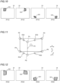
- the robot controller 12 and the vision controller 30 set four calibration postures of the robot arm 11 so as to move the identification member 101 to four positions P2, P3, P4, and P5 in a predetermined reference plane S1 based on the acquired reference images 51a and 52a.
- the predetermined reference plane S1 includes a position P1, which is the position of the identification member 101 when the reference image 51a and the reference image 52a are captured.
- the reference plane S1 is a plane along the surface of the identification member 101 on which the identification points 101a are arranged.
- the vision controller 30 When moving the identification member 101 from the position P1 to the positions P2, P3, P4, and P5, the vision controller 30 outputs, to the robot controller 12, a signal indicating a movement amount for moving the identification member 101 along the surface of the identification member 101 on which the identification points 101a are arranged.
- the robot controller 12 sets the four calibration postures of the robot arm 11 such that the identification member 101 is located at each of the four corners of the calibration images 51 and 52 by moving the identification member 101 to the four positions P2, P3, P4, and P5 in the predetermined reference plane S1 based on the signal indicating the movement amount acquired from the vision controller 30.
- the calibration images 51 are illustrated, and illustration of the calibration images 52 is omitted.
- the positions P2, P3, P4, and P5 are calculated by the vision controller 30 such that the identification member 101 is included in both the field of view 21a of the imager 21 and the field of view 22a of the imager 22.
- the vision controller 30 calculates the value of the movement amount that is the limit of the movement distance of the actual identification member 101 relative to the imagers 21 and 22 such that the identification member 101 is placed within the field of view 21a of the imager 21 and the field of view 22a of the imager 22, in each of the reference image 51a captured by the imager 21 and the reference image 52a captured by the imager 22. Then, the vision controller 30 acquires the positions P2, P3, P4, and P5 according to the reference image 51a or the reference image 52a, whichever has a smaller limit movement amount of the identification member 101. The robot controller 12 changes the posture of the robot arm 11 such that the identification member 101 is located at the positions P2, P3, P4, and P5.
- the robot controller 12 outputs, to the vision controller 30, a signal to instruct the vision controller 30 to capture the calibration images 51 and 52, and outputs a signal indicating a posture for placing the identification member 101 at each of the positions P2, P3, P4, and P5.
- the vision controller 30 corrects the positions P2, P3, P4, and P5. In such a case, the movement distance from the center position P1 is gradually decreased from the calculation result, for example. In other words, the value of the calculated limit movement amount is gradually decreased toward the center of the image. Then, the movement amounts corresponding to the corrected positions P2, P3, P4, and P5 are output again to the robot controller 12, and the calibration images 51 and 52 are captured again.
- the robot controller 12 After the calibration images 51 and 52 are acquired by imaging the identification member 101 located at the positions P2, P3, P4, and P5, the robot controller 12 further sets eight postures of the robot arm 11 so as to move the identification member 101 to a position between each of the four positions P2, P3, P4, and P5 in the reference plane S1 and a point on the far side, which is a first side in a direction perpendicular to the reference plane S1, and a position between each of the four positions P2, P3, P4, and P5 in the reference plane S1 and a point on the near side, which is a second side in the direction perpendicular to the reference plane S1.
- the robot controller 12 acquires four positions P12, P13, P14, and P15 to acquire four calibration postures on the far side, which is the first side in the direction perpendicular to the reference plane S1. After the position P1 is moved toward the far side, the robot controller 12 acquires the uppermost position of the field of view 21a of the imager 21 and the field of view 22a of the imager 22 as a position Pa and the lowermost position as a position Pb.
- the robot controller 12 acquires a midpoint between the position Pa and the position P2 as the position P12, a midpoint between the position Pa and the position P3 as the position P13, a midpoint between the position Pb and the position P4 as the position P14, and a midpoint between the position Pb and the position P5 as the position P15.
- the robot controller 12 outputs, to the vision controller 30, a signal to instruct the vision controller 30 to capture the calibration images 51 and 52, and outputs a signal indicating a posture for placing the identification member 101 at each of the positions P12, P13, P14, and P15.
- the robot controller 12 sets calibration postures such that the identification member 101 is placed at different angles relative to the imagers 21 and 22 from the reference posture at the positions P12, P13, P14, and P15.
- the calibration postures are set such that the identification member 101 is moved parallel to the reference plane S1 from the posture at the position P1, but at the positions P12, P13, P14, and P15, the surface of the identification member 101 on which the identification points 101a are arranged is placed so as not to face the reference plane S1.
- the identification member 101 is placed in a state rotated by a predetermined angle around at least one of the X direction, the Y direction, or the Z direction from the state in the reference posture.
- the angular directions at the positions P12, P13, P14, and P15 are preset.
- the robot controller 12 acquires four positions P22, P23, P24, and P25 to acquire four calibration postures on the near side, which is the second side in the direction perpendicular to the reference plane S1. After the position P1 is moved toward the near side, the robot controller 12 acquires the uppermost position of the field of view 21a of the imager 21 and the field of view 22a of the imager 22 as a position Pc and the lowermost position as a position Pd.
- the robot controller 12 acquires a midpoint between the position Pc and the position P2 as the position P22, a midpoint between the position Pc and the position P3 as the position P23, a midpoint between the position Pd and the position P4 as the position P24, and a midpoint between the position Pd and the position P5 as the position P25.
- the robot controller 12 outputs, to the vision controller 30, a signal to instruct the vision controller 30 to capture the calibration images 51 and 52, and outputs a signal indicating a posture for placing the identification member 101 at each of the positions P22, P23, P24, and P25.
- the surface of the identification member 101 on which the identification points 101a are arranged is placed so as not to face the reference plane S1.
- the identification member 101 is placed in a state rotated by a predetermined angle around at least one of the X direction, the Y direction, or the Z direction from the state in the reference posture.
- the angular directions at the positions P22, P23, P24, and P25 are also preset.
- FIGS. 8 , 10, and 12 show examples of only the calibration images 51, but the same applies to the calibration images 52. In the calibration images 51 in FIGS. 8 , 10, and 12 , illustration of the robot arm 11 is omitted.
- the distances of the positions Pa and Pb toward the far side from the reference plane S1 are preset.
- the distances toward the far side may be changed based on an input operation by the operator.
- the distances of the positions Pc and Pd toward the near side from the reference plane S1 are also preset and may be changed by the operator.
- the angular directions at the positions P12, P13, P14, and P15 and the angular directions at the positions P22, P23, P24, and P25 may be changed by an input operation by the operator.
- the robot controller 12 sets, as calibration postures, thirteen postures that are obtained by adding the reference posture to the twelve calibration postures set based on the reference posture. Then, the vision controller 30 acquires thirteen calibration images 51 and thirteen calibration images 52 by capturing images with the imager 21 and the imager 22 in the thirteen set calibration postures. Then, the vision controller 30 performs the calibration operation by performing the computation process to associate the position information of the robot arm 11 with the position information of the imagers 21 and 22, based on the position of the identification member 101 in each of the acquired thirteen calibration images 51 and thirteen calibration images 52 and the posture of the robot arm 11 at the time at which each of the thirteen calibration images 51 and the thirteen calibration images 52 is captured.
- the vision controller 30 detects the coordinates of the identification points 101a on the identification member 101 in each of the acquired thirteen calibration images 51 and thirteen calibration images 52. Then, the vision controller 30 performs the computation process to associate the coordinate system of the robot 10, which is the position information of the robot arm 11, with each of the coordinate systems of the imager 21 and the imager 22 by associating the coordinates of the identification points 101a in each of the thirteen calibration images 51 and the thirteen calibration images 52 with the thirteen calibration postures.
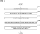
- a method for controlling the robot system 100 is now described with reference to FIG. 13 .
- the method for controlling the robot system 100 is performed by the robot controller 12 and the vision controller 30 performing the control processes.
- step S101 the calibration operation is started, and the reference image 51a and the reference image 52a are acquired.
- the robot arm 11 is set to one reference posture based on an operation by the operator.
- the identification member 101 for calibration is imaged using the imager 21 and the imager 22 while the robot arm 11 is placed in the reference posture such that one reference image 51a and one reference image 52a are acquired.
- step S102 a plurality of calibration postures of the robot arm 11 are set based on the acquired reference images 51a and 52a such that the identification member 101 is imaged by each of the imager 21 and the imager 22 while being included in both the field of view 21a of the imager 21 and the field of view 22a of the imager 22.
- thirteen calibration postures are set such that the identification member 101 is placed at the thirteen positions, namely the positions P1, P2, P3, P4, and P5, the positions P12, P13, P14, and P15, and the positions P22, P23, P24, and P25.
- step S103 a plurality of calibration images 51 and 52 captured by the imager 21 and the imager 22 in the plurality of set calibration postures are acquired. Specifically, the identification member 101 is imaged in each of the thirteen calibration postures such that thirteen calibration images 51 and thirteen calibration images 52 are acquired.
- step S104 based on the position of the identification member 101 in each of the acquired thirteen calibration images 51 and thirteen calibration images 52 and the posture of the robot arm 11 at the time at which each of the thirteen calibration images 51 and the thirteen calibration images 52 is captured, the computation process for the calibration operation is performed to associate the position information of the robot arm 11 with the position information of the image 41 captured by the imager 21 and the image 42 captured by the imager 22.
- step S101 to step S104 the calibration operation is performed to associate the position information of the robot arm 11, to which the hand H configured to perform an operation on the workpiece W is attached, with the position information of the captured images 41 and 42, which are images captured by the imager 21 and the imager 22 configured to image the workpiece W.
- step S101 to step S104 the operation of the robot arm 11 is controlled based on the image 41 captured by the imager 21 and the image 42 captured by the imager 22 in step S105.
- the robot controller 12 and the vision controller 30 are configured or programmed to acquire the reference image 51a, which is one captured image 41 obtained by imaging the identification member 101 for calibration with the imager 21 while the robot arm 11 is placed in one reference posture.
- the robot controller 12 and the vision controller 30 are also configured or programmed to acquire, in the calibration operation, the reference image 52a, which is one captured image 42 obtained by imaging the identification member 101 for calibration with the imager 22 while the robot arm 11 is placed in the reference posture.
- the robot controller 12 and the vision controller 30 are configured or programmed to set, in the calibration operation, the plurality of calibration postures of the robot arm 11 based on the acquired reference images 51a and 52a such that the imager 21 and the imager 22 image the identification member 101 in a state in which the identification member 101 is included in the field of view 21a of the imager 21 and the field of view 22a of the imager 22. Furthermore, the robot controller 12 and the vision controller 30 are configured or programmed to acquire, for each of the plurality of set calibration postures, the calibration image 51, which is the captured image 41 for calibration obtained by imaging the identification member 101 with the imager 21, and the calibration image 52, which is the captured image 42 for calibration obtained by imaging the identification member 101 with the imager 22.
- the plurality of calibration postures of the robot arm 11 are set based on the reference image 51a, which is one captured image 41, and the reference image 52a, which is one captured image 42, and thus as compared with a case in which the calibration postures are set by performing rough transformation in advance based on a plurality of captured images, such as a three-point calibration, it is possible to decrease the time required for the control processes for setting the calibration postures, and decrease the processing amount in the control processes. Consequently, in the calibration operation to associate the position information of the robot arm 11 with the position information of the captured images 41 and 42, increases in the time and processing amount required for the control processes can be reduced or prevented.
- the robot controller 12 and the vision controller 30 are configured or programmed to set the plurality of calibration postures of the robot arm 11 based on the distance D of the identification position on the actual identification member 101 and the distance D of the identification position on the on-image identification member 101 in the reference images 51a and 52a. Accordingly, by comparing the distance D of the identification position on the actual identification member 101 with the distance D of the identification position on the on-image identification member 101 in the reference images 51a and 52a, the value that is the limit of the movement distance of the actual identification member 101 relative to the imagers 21 and 22 can be easily acquired such that the identification member 101 is placed within the field of view 21a of the imager 21 and the field of view 22a of the imager 22.
- the calibration postures are set based on the distance D of the identification position on the actual identification member 101 and the distance D of the identification position on the on-image identification member 101 in the reference images 51a and 52a such that the calibration postures can be easily set such that the identification member 101 is included in the field of view 21a of the imager 21 and the field of view 22a of the imager 22.
- the identification member 101 includes the plurality of identification points 101a
- the robot controller 12 and the vision controller 30 are configured or programmed to acquire the distance D of the identification position on the actual identification member 101 based on the actual distance between the plurality of identification points 101a, and acquire the distance D of the identification position on the on-image identification member 101 based on the distance between the plurality of on-image identification points 101a in the reference images 51a and 52a in which the plurality of identification points 101a are imaged so as to set the plurality of calibration postures of the robot arm 11.
- the distance between the plurality of identification points 101a on the identification member 101 is acquired such that it is possible to more easily acquire the distance D of the identification position on the actual identification member 101 and the distance D of the identification position on the on-image identification member 101 in the reference images 51a and 52a . Therefore, the calibration postures can be set more easily such that the identification position on the identification member 101 is included in the field of view 21a of the imager 21 and the field of view 22a of the imager 22.
- the identification member 101 includes the plate-shaped member on which the plurality of identification points 101a are arranged in a lattice pattern
- the robot controller 12 and the vision controller 30 are configured or programmed to acquire the distance D of the identification position on the actual identification member 101 based on the actual distance between the identification points 101a at the four corners among the plurality of identification points 101a arranged in a lattice pattern, and acquire the distance D of the identification position on the on-image identification member 101 based on the distance between the on-image identification points 101a at the four corners in the reference images 51a and 52a in which the plurality of identification points 101a arranged in a lattice pattern are imaged so as to set the plurality of calibration postures of the robot arm 11.
- the distance between the identification points 101a at the four corners among the plurality of identification points 101a arranged in a lattice pattern is acquired such that it is possible to still more easily acquire the distance D of the identification position on the actual identification member 101 and the distance D of the identification position on the on-image identification member 101 in the reference images 51a and 52a. Therefore, it is possible to still more easily set the calibration postures such that the identification position on the identification member 101 is included in the field of view 21a of the imager 21 and the field of view 22a of the imager 22.
- the robot system 100 includes the imager 21 fixed to the first position different from the robot arm 11 to image the workpiece W, and the imager 22 fixed to the second position different from the robot arm 11 separately from the imager 21 to image the workpiece W together with the imager 21.
- the robot controller 12 and the vision controller 30 are configured or programmed to perform the calibration operation to associate the position information of the robot arm 11 to the position information of each of the captured image 41, which is a captured image captured by the imager 21, and the captured image 42, which is a captured image captured by the imager 22, in order to operate the robot arm 11 based on the captured image 41 and the captured image 42.
- the robot controller 12 and the vision controller 30 are configured or programmed to acquire, in the calibration operation, the reference image 51a, which is one captured image 41 obtained by imaging the identification member 101 arranged on the hand H with the imager 21 while the robot arm 11 is placed in the reference posture, and the reference image 52a, which is one captured image 42 obtained by imaging the identification member 101 arranged on the hand H with the imager 22 while the robot arm 11 is placed in the reference posture, to set, in the calibration operation, the plurality of calibration postures of the robot arm 11 based on the acquired reference images 51a and 52a such that the imager 21 and the imager 22 image the identification member 101 in a state in which the identification member 101 is included in the field of view 21a of the imager 21 and the field of view 22a of the imager 22, and to acquire, for each of the plurality of set calibration postures, the calibration image 51 and the calibration image 52 captured by the imager 21 and the imager 22, respectively.
- the plurality of calibration postures of the robot arm 11 can be set such that the identification member 101 is imaged by each of the imager 21 and the imager 22 in a state in which the identification member 101 is included in the field of view 21a of the imager 21 and the field of view 22a of the imager 22, and thus even when two different imagers 21 and 22 are used to three-dimensionally control the operation of the robot arm 11, increases in the time and processing amount required for the control processes can be reduced or prevented in the calibration operation to associate the position information of the robot arm 11 with the position information of each of the captured images 41 and 42.
- the robot controller 12 and the vision controller 30 are configured or programmed to acquire the reference images 51a and 52a captured such that the identification member 101 is located at the approximate center of the image, to set the four postures of the robot arm 11 such that the identification member 101 is located at each of the four corners of the calibration images 51 and 52 by moving the identification member 101 to the four positions P2, P3, P4, and P5 in the predetermined reference plane S1 including the position P1 of the identification member 101 at the time of capturing the reference images 51a and 52a based on the acquired reference images 51a and 52a, and to set the eight postures of the robot arm 11 such that the identification member 101 is moved to each of the positions P12, P13, P14, and P15 between the four positions P2, P3, P4, and P5 in the reference plane S1 and the point on the first side in the direction perpendicular to the reference plane S1, and each of the positions P22, P23, P24, and P25 between the four positions P2, P3, P4, and P5 in the reference plane S1 and
- the thirteen calibration postures can be set such that the identification member 101 is moved three-dimensionally relative to the imagers 21 and 22. Therefore, the identification member 101 is moved three-dimensionally such that the position information of the robot arm 11 and the position information of the captured images 41 and 42 can be accurately associated with each other in the calibration operation.
- the calibration operation may be performed by imaging an identification member arranged at a position at which the workpiece on which an operation is to be performed is placed with an imager placed on the robot arm. That is, an operation may be performed on the workpiece while the workpiece is imaged with the imager placed on the robot arm.
- one reference image is acquired, and a plurality of calibration postures are set based on the distance of the identification position on the on-image identification member in the reference image and the distance of the identification position on the actual identification member.
- the present disclosure is not limited to this.
- the distance of the identification position on the identification member may not be the distance between the identification points.
- a cross-shaped symbol or a rectangular symbol, the size of which can be identified may be arranged on the identification member.
- the identification points may not be arranged in a lattice pattern, but only four identification points may be provided.
- the present disclosure is not limited to this.
- a single imager may be used to control the operation of the robot arm.
- the present disclosure is not limited to this. In the present disclosure, more than thirteen calibration postures may be set. Alternatively, fewer than thirteen calibration postures may be set. Furthermore, the calibration postures may be postures in which the identification member is arranged at a position different from that in the example of the above embodiment. Moreover, the angle of the identification member in the thirteen calibration postures may be different from that in the example of the above embodiment.
- the robot arm 11 may be configured to perform operations to manufacture and assemble a workpiece.
- the present disclosure is not limited to this.
- the calibration operation may be controlled by a single control device as a controller.
- the robot controller that controls the operation of the robot arm may perform the computation process to associate the position information of the robot with the position information of the captured images, instead of the vision controller that acquires the captured image.
- the robot controller may perform a control to detect the identification member from the calibration image.
- circuitry or processing circuitry that includes general purpose processors, special purpose processors, integrated circuits, application specific integrated circuits (ASICs), conventional circuitry and/or combinations thereof that are configured or programmed to perform the disclosed functionality.
- Processors are considered processing circuitry or circuitry as they include transistors and other circuitry therein.
- the circuitry, units, or means are hardware that carries out the recited functionality or hardware that is programmed to perform the recited functionality.
- the hardware may be hardware disclosed herein or other known hardware that is programmed or configured to carry out the recited functionality.
- the hardware is a processor that may be considered a type of circuitry
- the circuitry, means, or units are a combination of hardware and software, and the software is used to configure the hardware and/or processor.
- a robot system comprising:
- a method for controlling a robot system comprising:
Landscapes
- Engineering & Computer Science (AREA)
- Robotics (AREA)
- Mechanical Engineering (AREA)
- Computer Vision & Pattern Recognition (AREA)
- Physics & Mathematics (AREA)
- General Physics & Mathematics (AREA)
- Theoretical Computer Science (AREA)
- Multimedia (AREA)
- Human Computer Interaction (AREA)
- Manipulator (AREA)
Abstract
Description
- The present disclosure relates to a robot system and a method for controlling a robot system.
- Conventionally, a robot system is known that controls the operation of a robot arm based on a captured image captured by an imager. For example,
Japanese Patent Laid-Open No. 2022-028672 Japanese Patent Laid-Open No. 2022-028672 - In the system described in
Japanese Patent Laid-Open No. 2022-028672 - Patent Document 1:
Japanese Patent Laid-Open No. 2022- 028672 - In the robot system described in
Japanese Patent Laid-Open No. 2022-028672 - The present disclosure is intended to solve the above problems. The present disclosure aims to provide a robot system and a method for controlling a robot system each capable of reducing or preventing increases in the time and processing amount required for a control process in a calibration operation to associate position information of a robot arm with position information of a captured image.
- In order to attain the aforementioned object, a robot system according to a first aspect of the present disclosure includes a robot arm to which a hand operable to perform an operation on a workpiece is attached, an imager to image the workpiece, and a controller configured or programmed to perform a calibration operation to associate position information of the robot arm with position information of a captured image captured by the imager in order to operate the robot arm based on the captured image. The controller is configured or programmed to acquire a reference image, which is the captured image obtained by imaging an identification member for calibration with the imager while the robot arm is placed in one posture, set, in the calibration operation, a plurality of calibration postures of the robot arm based on the reference image that has been acquired such that the imager images the identification member in a state in which the identification member is included in a field of view of the imager, and acquire, for each of the plurality of calibration postures that have been set, a calibration image, which is the captured image for calibration obtained by imaging the identification member with the imager.
- In the robot system according to the first aspect of the present disclosure, as described above, the controller is configured or programmed to acquire the reference image, which is one captured image obtained by imaging the identification member for calibration with the imager while the robot arm is placed in the one posture. The controller is configured or programmed to set, in the calibration operation, the plurality of calibration postures of the robot arm based on the acquired reference image such that the imager images the identification member in a state in which the identification member is included in the field of view of the imager. Furthermore, the controller is configured or programmed to acquire, for each of the plurality of set calibration postures, the calibration image, which is the captured image for calibration obtained by imaging the identification member with the imager. Accordingly, the plurality of calibration postures of the robot arm are set based on the reference image, which is one captured image, and thus as compared with a case in which the calibration postures are set by performing rough transformation in advance based on a plurality of captured images, such as a three-point calibration, it is possible to decrease the time required for a control process for setting the calibration postures, and decrease the processing amount in the control process. Consequently, in the calibration operation to associate the position information of the robot arm with the position information of the captured image, increases in the time and processing amount required for the control process can be reduced or prevented.
- In order to attain the aforementioned object, a method for controlling a robot system according to a second aspect of the present disclosure includes performing a calibration operation to associate position information of a robot arm to which a hand operable to perform an operation on a workpiece is attached with position information of a captured image captured by an imager operable to image the workpiece, and controlling operation of the robot arm based on the captured image captured by the imager after performing the calibration operation. The performing the calibration operation includes acquiring a reference image, which is the captured image obtained by imaging an identification member for calibration with the imager while the robot arm is placed in one posture, setting a plurality of calibration postures of the robot arm based on the reference image that has been acquired such that the imager images the identification member in a state in which the identification member is included in a field of view of the imager, and acquiring, for each of the plurality of calibration postures that have been set, a calibration image, which is the captured image for calibration obtained by imaging the identification member with the imager.
- In the method for controlling the robot system according to the second aspect of the present disclosure, as described above, the reference image is acquired, which is one captured image obtained by imaging the identification member for calibration with the imager while the robot arm is placed in the one posture. The plurality of calibration postures of the robot arm are set based on the acquired reference image in the calibration operation such that the imager images the identification member in a state in which the identification member is included in the field of view of the imager. Furthermore, the calibration image, which is the captured image for calibration obtained by imaging the identification member with the imager, is acquired for each of the plurality of set calibration postures. Accordingly, the plurality of calibration postures of the robot arm are set based on the reference image, which is one captured image, and thus as compared with a case in which the calibration postures are set by performing rough transformation in advance based on a plurality of captured images, such as a three-point calibration, it is possible to decrease the time required for a control process for setting the calibration postures, and decrease the processing amount in the control process. Consequently, it is possible to provide the method for controlling a robot system capable of reducing or preventing increases in the time and processing amount required for the control process in the calibration operation to associate the position information of the robot arm with the position information of the captured image.
- According to the present disclosure, as described above, it is possible to provide the robot system and the method for controlling a robot system each capable of reducing or preventing increases in the time and processing amount required for the control process in the calibration operation to associate the position information of the robot arm with the position information of the captured image.
-
-
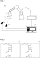
FIG. 1 is a schematic view showing the overall configuration of a robot system according to an embodiment of the present disclosure. -
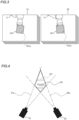
FIG. 2 is a diagram showing examples of captured images captured by each of two imagers. -
FIG. 3 is a diagram for illustrating a plurality of calibration images for calibration. -
FIG. 4 is a diagram for illustrating an arrangement of the fields of view of the two imagers and an identification member. -
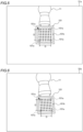
FIG. 5 is a diagram showing an example of areference image 51a. -
FIG. 6 is a diagram showing an example of areference image 52a. -
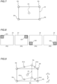
FIG. 7 is a diagram for illustrating acquisition of four calibration postures in a reference plane. -
FIG. 8 is a diagram showing an example of calibration images in the four calibration postures in the reference plane. -
FIG. 9 is a diagram for illustrating acquisition of four calibration postures behind the reference plane. -
FIG. 10 is a diagram showing an example of calibration images in the four calibration postures behind the reference plane. -
FIG. 11 is a diagram for illustrating acquisition of four calibration postures in front of the reference plane. -
FIG. 12 is a diagram showing an example of calibration images in the four calibration postures in front of the reference plane. -
FIG. 13 is a flowchart showing a method for controlling the robot system according to the embodiment of the present disclosure. - An embodiment embodying the present disclosure is hereinafter described on the basis of the drawings.
- The configuration of a
robot system 100 according to the embodiment of the present disclosure is now described with reference toFIGS. 1 to 12 . - As shown in
FIG. 1 , therobot system 100 is a system in which arobot arm 11 performs an operation on a workpiece W imaged by animager 21 and animager 22. For example, therobot arm 11 performs an operation to transfer the workpiece W arranged in the vicinity of therobot arm 11 to a predetermined location. In an example shown inFIG. 1 , the workpiece W is a cardboard box. - The
robot system 100 includes arobot 10, theimager 21, theimager 22, and avision controller 30. Theimager 21 is an example of an "imager" or a "first imager" in the claims. Theimager 22 is an example of an "imager" or a "second imager" in the claims. Thevision controller 30 is an example of a "controller" in the claims. - The
robot 10 includes therobot arm 11 and arobot controller 12. Therobot arm 11 is a vertical articulated robot arm including a plurality of joints. A hand H that performs an operation on the workpiece W is attached to therobot arm 11. For example, the hand H grips the workpiece W. The hand H is attached to a distal end of therobot arm 11. Therobot arm 11 is controlled by therobot controller 12 to operate the plurality of joints. For example, therobot arm 11 operates due to driving of drives such as servomotors provided at the plurality of joints. Therobot controller 12 is an example of a "controller" in the claims. - The
robot controller 12 controls the operation of therobot arm 11. Therobot controller 12 also controls the operation of the hand H attached to therobot arm 11. Therobot controller 12 includes, for example, a processor such as a central processing unit (CPU) and a memory to store information. Therobot controller 12 communicates with thevision controller 30. - The
imager 21 and theimager 22 image the workpiece W. Theimager 21 and theimager 22 include an imaging device such as a complementary metal-oxide semiconductor (CMOS) image sensor or a charge coupled device (CCD) image sensor. Theimager 21 is arranged at a first location different from therobot arm 11. Theimager 22 is arranged at a second location different from therobot arm 11, separately from theimager 21. Each of the first location and the second location is, for example, a floor surface, a wall surface, or a base of therobot arm 11, which is spaced apart from therobot arm 11. That is, theimager 21 and theimager 22 are fixed and arranged at locations at which the workpiece W is imaged, separately from the operation of therobot arm 11. Each of theimager 21 and theimager 22 is placed so as to image a common workpiece W. Theimager 21 and theimager 22 are arranged as stereo cameras configured to acquire the three-dimensional position of the workpiece W. Therefore, theimager 21 and theimager 22 are fixed while being spaced apart from each other by a predetermined distance in a right-left direction in order to identify the position of the workpiece W by triangulation. Theimager 21 and theimager 22 are connected in parallel to each other to thevision controller 30. - The
vision controller 30 is an image processor that processes images captured by theimager 21 and theimager 22. Thevision controller 30 includes a personal computer including processors such as a CPU and a graphics processing unit (GPU), a memory to store information, and a storage such as a hard disk drive (HDD) or a solid state drive (SSD), for example. - As shown in
FIG. 2 , thevision controller 30 controls theimager 21 and theimager 22 to acquire a capturedimage 41 captured by theimager 21 and a capturedimage 42 captured by theimager 22. Thevision controller 30 then performs image processing on the capturedimages images image 41 is an example of a "first captured image" or a "captured image" in the claims. The capturedimage 42 is an example of a "second captured image" or a "captured image" in the claims. - In the
robot system 100, therobot arm 11 grips the workpiece W based on the capturedimages imager 21 andimager 22, through control processes by therobot controller 12 and thevision controller 30. Thevision controller 30 outputs a signal to therobot controller 12 to control the operation of therobot arm 11 based on theimages imager 21 and theimager 22. Specifically, thevision controller 30 performs image processing on theimage 41 captured by theimager 21 and theimage 42 captured by theimager 22 to acquire the three-dimensional position of the workpiece W in order to control the operation of therobot arm 11. Thevision controller 30 then outputs a signal indicating the acquired three-dimensional position of the workpiece W to therobot controller 12. Therobot controller 12 controls the operation of therobot arm 11 to perform an operation on the workpiece W based on the signal from thevision controller 30. That is, therobot controller 12 recognizes the three-dimensional position of the workpiece W based on the signal from thevision controller 30. Then, based on the recognized position of the workpiece W, therobot controller 12 operates therobot arm 11 and the hand H such that the hand H attached to therobot arm 11 grips the workpiece W. - In the
robot system 100, when therobot arm 11 grips the workpiece W based on the capturedimages imager 21 and theimager 22 and the coordinate system of therobot arm 11. Therefore, therobot controller 12 and thevision controller 30 perform a calibration operation to associate position information of therobot arm 11 with position information of the capturedimages robot arm 11 based on theimages imager 21 and theimager 22. That is, in this embodiment, therobot controller 12 and thevision controller 30 operate as controllers that perform the calibration operation by performing the control processes while communicating with each other. The calibration operation is performed when therobot system 100 is installed or when theimager 21 and theimager 22 are replaced, for example. - As shown in
FIG. 3 , in the calibration operation, anidentification member 101 for calibration attached to the hand H at the distal end of therobot arm 11 is imaged a plurality of times by theimager 21 and theimager 22 while the posture of therobot arm 11 is changed by therobot controller 12 such that a plurality ofcalibration images 51, which are a plurality of capturedimages 41 for calibration, and a plurality ofcalibration images 52, which are a plurality of capturedimages 42 for calibration, are acquired by thevision controller 30. Then, thevision controller 30 identifies the position and angle of theidentification member 101 for calibration contained in the plurality ofcalibration images 51 and the plurality ofcalibration images 52 by image processing to perform a computation process to associate the position information of therobot arm 11 with the position information of the capturedimage 41 and the capturedimage 42. Theidentification member 101 is a plate-shaped member on which a plurality ofidentification points 101a are arranged in a lattice pattern. - Specifically, as shown in
FIG. 4 , in the calibration operation, therobot controller 12 moves therobot arm 11 to a plurality of calibration postures to place theidentification member 101 attached to the hand H at a position included in both the field ofview 21a of theimager 21 and the field ofview 22a of theimager 22. Thevision controller 30 controls theimager 21 and theimager 22 to image theidentification member 101 placed at the position included in both the field ofview 21a of theimager 21 and the field ofview 22a of theimager 22 for each of the plurality of calibration postures. In this embodiment, therobot controller 12 automatically sets the plurality of calibration postures of therobot arm 11. The posture of therobot arm 11 in this description refers to the arrangement position and arrangement angle of therobot arm 11. - As shown in
FIG. 5 , in the calibration operation, areference image 51a is first acquired as a reference to acquire the plurality of calibration postures. In this embodiment, thevision controller 30 acquires thereference image 51a obtained by imaging theidentification member 101 with theimager 21 while therobot arm 11 is placed in one reference posture. Thereference image 51a is one capturedimage 41 obtained by imaging theidentification member 101 arranged on therobot arm 11 in the reference posture with theimager 21. In the reference posture, theidentification member 101 is located at a position that is an approximate center of the field ofview 21a of theimager 21 and also an approximate center of the field ofview 22a of theimager 22. Therefore, thereference image 51a is captured such that theidentification member 101 is located at an approximate center of the image. Thereference image 51a is an example of a "reference image" or a "first reference image" in the claims. - As shown in
FIG. 6 , similarly to thereference image 51a, in order to acquire the plurality of calibration postures, onereference image 52a is acquired by imaging theidentification member 101 arranged on the hand H of therobot arm 11 with theimager 22 while therobot arm 11 is placed in one reference posture. Similarly to thereference image 51a, thereference image 52a captured by theimager 22 is captured such that theidentification member 101 is located at an approximate center of the image. Thereference image 52a is an example of a "reference image" or a "second reference image" in the claims. - In the reference posture, the
identification member 101 is arranged such that a surface of theidentification member 101 on which theidentification points 101a are arranged faces both theimager 21 and theimager 22. Theimager 21 and theimager 22 are spaced apart from each other, and thus theidentification member 101 is arranged such that the surface on which theidentification points 101a are arranged faces a midpoint between the positions of theimager 21 and theimager 22 while theidentification member 101 is arranged on therobot arm 11 in the reference posture. Therefore, in both thereference image 51a and thereference image 52a, theidentification member 101 is imaged with the surface on which the plurality ofidentification points 101a are arranged facing substantially forward. - The control amount for placing the
robot arm 11 in the reference posture is set based on an input by an operator. For example, thevision controller 30 displays the capturedimages imager 21 and theimager 22, on a display (not shown) such as a display connected to thevision controller 30, and displays a cross-shaped image or the like for identifying a center position, superimposed on each of the capturedimages identification member 101 at the center position of both the field ofview 21a of theimager 21 and the field ofview 22a of theimager 22 while visually recognizing the cross shape for identifying the center position on the display (not shown). For example, based on an input operation on an operation unit (not shown) such as a keyboard or a mouse connected to thevision controller 30 or therobot controller 12, therobot controller 12 changes the posture of therobot arm 11 to adjust the arrangement of theidentification member 101 so as to set the reference posture. - In this embodiment, the
robot controller 12 and thevision controller 30 set, in the calibration operation, the plurality of calibration postures of therobot arm 11 based on the acquiredreference images imager 21 and theimager 22 image theidentification member 101 in a state in which theidentification member 101 is included in both the field ofview 21a of theimager 21 and the field ofview 22a of theimager 22. Therobot controller 12 and thevision controller 30 set the plurality of calibration postures of therobot arm 11 based on the distance D of an identification position on theactual identification member 101 and the distance D of an identification position on the on-image identification member 101 in thereference image 51a in the calibration operation. The distance D of the identification position is a distance between a plurality ofidentification points 101a on theidentification member 101. For example, the distance D of the identification position is a distance betweenidentification points 101a at the four corners among the plurality ofidentification points 101a arranged in a lattice pattern. - Specifically, the
vision controller 30 detects aframe line 101b included in theidentification member 101 in each of the acquiredreference images vision controller 30 identifies each of the plurality ofidentification points 101a included inside theframe line 101b, which are arranged in a lattice pattern. Then, thevision controller 30 acquires the distance between theidentification points 101a at the four corners among the plurality ofidentification points 101a to acquire the distance D of the identification position on the on-image identification member 101 in thereference images image identification member 101 is, for example, a numerical value expressed by the number of pixels. Furthermore, the distance D of the identification position on the on-image identification member 101 is acquired, for example, along the horizontal direction and the vertical direction of the image. Then, thevision controller 30 stores in advance the distance D of the actual identification position, which is the distance between theidentification points 101a at the four corners of theactual identification member 101. - The
vision controller 30 compares the distance D of the identification position on theactual identification member 101 with the distance D of the identification position on the on-image identification member 101 in thereference images robot arm 11 can move theidentification member 101, which is included in both the field ofview 21a of theimager 21 and the field ofview 22a of theimager 22, without theidentification member 101 going out of the field ofview 21a and the field ofview 22a. Then, thevision controller 30 outputs the calculated movement amount to therobot controller 12. Therobot controller 12 acquires the movement amount output from thevision controller 30 and sets a calibration posture based on the acquired movement amount. In this embodiment, therobot controller 12 and thevision controller 30 set twelve calibration postures to acquire thecalibration images reference images 51a and 51b. - As shown in
FIG. 7 , therobot controller 12 and thevision controller 30 set four calibration postures of therobot arm 11 so as to move theidentification member 101 to four positions P2, P3, P4, and P5 in a predetermined reference plane S1 based on the acquiredreference images identification member 101 when thereference image 51a and thereference image 52a are captured. The reference plane S1 is a plane along the surface of theidentification member 101 on which theidentification points 101a are arranged. When moving theidentification member 101 from the position P1 to the positions P2, P3, P4, and P5, thevision controller 30 outputs, to therobot controller 12, a signal indicating a movement amount for moving theidentification member 101 along the surface of theidentification member 101 on which theidentification points 101a are arranged. - As shown in
FIG. 8 , therobot controller 12 sets the four calibration postures of therobot arm 11 such that theidentification member 101 is located at each of the four corners of thecalibration images identification member 101 to the four positions P2, P3, P4, and P5 in the predetermined reference plane S1 based on the signal indicating the movement amount acquired from thevision controller 30. InFIG. 8 , only thecalibration images 51 are illustrated, and illustration of thecalibration images 52 is omitted. The positions P2, P3, P4, and P5 are calculated by thevision controller 30 such that theidentification member 101 is included in both the field ofview 21a of theimager 21 and the field ofview 22a of theimager 22. That is, thevision controller 30 calculates the value of the movement amount that is the limit of the movement distance of theactual identification member 101 relative to theimagers identification member 101 is placed within the field ofview 21a of theimager 21 and the field ofview 22a of theimager 22, in each of thereference image 51a captured by theimager 21 and thereference image 52a captured by theimager 22. Then, thevision controller 30 acquires the positions P2, P3, P4, and P5 according to thereference image 51a or thereference image 52a, whichever has a smaller limit movement amount of theidentification member 101. Therobot controller 12 changes the posture of therobot arm 11 such that theidentification member 101 is located at the positions P2, P3, P4, and P5. Each time theidentification member 101 is placed at each of the positions P2, P3, P4, and P5, therobot controller 12 outputs, to thevision controller 30, a signal to instruct thevision controller 30 to capture thecalibration images identification member 101 at each of the positions P2, P3, P4, and P5. When thecalibration images identification member 101 at the positions P2, P3, P4, and P5 do not include a portion or the whole of theidentification member 101, thevision controller 30 corrects the positions P2, P3, P4, and P5. In such a case, the movement distance from the center position P1 is gradually decreased from the calculation result, for example. In other words, the value of the calculated limit movement amount is gradually decreased toward the center of the image. Then, the movement amounts corresponding to the corrected positions P2, P3, P4, and P5 are output again to therobot controller 12, and thecalibration images - After the
calibration images identification member 101 located at the positions P2, P3, P4, and P5, therobot controller 12 further sets eight postures of therobot arm 11 so as to move theidentification member 101 to a position between each of the four positions P2, P3, P4, and P5 in the reference plane S1 and a point on the far side, which is a first side in a direction perpendicular to the reference plane S1, and a position between each of the four positions P2, P3, P4, and P5 in the reference plane S1 and a point on the near side, which is a second side in the direction perpendicular to the reference plane S1. - For example, as shown in
FIG. 9 , therobot controller 12 acquires four positions P12, P13, P14, and P15 to acquire four calibration postures on the far side, which is the first side in the direction perpendicular to the reference plane S1. After the position P1 is moved toward the far side, therobot controller 12 acquires the uppermost position of the field ofview 21a of theimager 21 and the field ofview 22a of theimager 22 as a position Pa and the lowermost position as a position Pb. Then, therobot controller 12 acquires a midpoint between the position Pa and the position P2 as the position P12, a midpoint between the position Pa and the position P3 as the position P13, a midpoint between the position Pb and the position P4 as the position P14, and a midpoint between the position Pb and the position P5 as the position P15. - Then, as shown in
FIG. 10 , each time theidentification member 101 is placed at each of the positions P12, P13, P14, and P15, therobot controller 12 outputs, to thevision controller 30, a signal to instruct thevision controller 30 to capture thecalibration images identification member 101 at each of the positions P12, P13, P14, and P15. Therobot controller 12 sets calibration postures such that theidentification member 101 is placed at different angles relative to theimagers identification member 101 is moved parallel to the reference plane S1 from the posture at the position P1, but at the positions P12, P13, P14, and P15, the surface of theidentification member 101 on which theidentification points 101a are arranged is placed so as not to face the reference plane S1. For example, when mutually perpendicular directions in the reference plane S1 are defined as an X direction and a Y direction, and a direction perpendicular to the reference plane S1 is defined as a Z direction, at the positions P12, P13, P14, and P15, theidentification member 101 is placed in a state rotated by a predetermined angle around at least one of the X direction, the Y direction, or the Z direction from the state in the reference posture. The angular directions at the positions P12, P13, P14, and P15 are preset. - As shown in
FIG. 11 , similarly to the case on the far side, therobot controller 12 acquires four positions P22, P23, P24, and P25 to acquire four calibration postures on the near side, which is the second side in the direction perpendicular to the reference plane S1. After the position P1 is moved toward the near side, therobot controller 12 acquires the uppermost position of the field ofview 21a of theimager 21 and the field ofview 22a of theimager 22 as a position Pc and the lowermost position as a position Pd. Then, therobot controller 12 acquires a midpoint between the position Pc and the position P2 as the position P22, a midpoint between the position Pc and the position P3 as the position P23, a midpoint between the position Pd and the position P4 as the position P24, and a midpoint between the position Pd and the position P5 as the position P25. - Then, as shown in
FIG. 12 , each time theidentification member 101 is placed at each of the positions P22, P23, P24, and P25, therobot controller 12 outputs, to thevision controller 30, a signal to instruct thevision controller 30 to capture thecalibration images identification member 101 at each of the positions P22, P23, P24, and P25. Similarly to the positions P12, P13, P14, and P15, at the positions P22, P23, P24, and P25, the surface of theidentification member 101 on which theidentification points 101a are arranged is placed so as not to face the reference plane S1. Similarly to the positions P12, P13, P14, and P15, at the positions P22, P23, P24, and P25, theidentification member 101 is placed in a state rotated by a predetermined angle around at least one of the X direction, the Y direction, or the Z direction from the state in the reference posture. The angular directions at the positions P22, P23, P24, and P25 are also preset.FIGS. 8 ,10, and 12 show examples of only thecalibration images 51, but the same applies to thecalibration images 52. In thecalibration images 51 inFIGS. 8 ,10, and 12 , illustration of therobot arm 11 is omitted. - The distances of the positions Pa and Pb toward the far side from the reference plane S1 are preset. The distances toward the far side may be changed based on an input operation by the operator. Similarly, the distances of the positions Pc and Pd toward the near side from the reference plane S1 are also preset and may be changed by the operator. The angular directions at the positions P12, P13, P14, and P15 and the angular directions at the positions P22, P23, P24, and P25 may be changed by an input operation by the operator.
- The
robot controller 12 sets, as calibration postures, thirteen postures that are obtained by adding the reference posture to the twelve calibration postures set based on the reference posture. Then, thevision controller 30 acquires thirteencalibration images 51 and thirteencalibration images 52 by capturing images with theimager 21 and theimager 22 in the thirteen set calibration postures. Then, thevision controller 30 performs the calibration operation by performing the computation process to associate the position information of therobot arm 11 with the position information of theimagers identification member 101 in each of the acquired thirteencalibration images 51 and thirteencalibration images 52 and the posture of therobot arm 11 at the time at which each of the thirteencalibration images 51 and the thirteencalibration images 52 is captured. Specifically, thevision controller 30 detects the coordinates of theidentification points 101a on theidentification member 101 in each of the acquired thirteencalibration images 51 and thirteencalibration images 52. Then, thevision controller 30 performs the computation process to associate the coordinate system of therobot 10, which is the position information of therobot arm 11, with each of the coordinate systems of theimager 21 and theimager 22 by associating the coordinates of theidentification points 101a in each of the thirteencalibration images 51 and the thirteencalibration images 52 with the thirteen calibration postures. - A method for controlling the
robot system 100 is now described with reference toFIG. 13 . The method for controlling therobot system 100 is performed by therobot controller 12 and thevision controller 30 performing the control processes. - As shown in
FIG. 13 , first, in step S101, the calibration operation is started, and thereference image 51a and thereference image 52a are acquired. Specifically, therobot arm 11 is set to one reference posture based on an operation by the operator. Then, theidentification member 101 for calibration is imaged using theimager 21 and theimager 22 while therobot arm 11 is placed in the reference posture such that onereference image 51a and onereference image 52a are acquired. - Next, in step S102, a plurality of calibration postures of the
robot arm 11 are set based on the acquiredreference images identification member 101 is imaged by each of theimager 21 and theimager 22 while being included in both the field ofview 21a of theimager 21 and the field ofview 22a of theimager 22. Specifically, based on the distance D of the identification position on theactual identification member 101 and the distance D of the identification position on the on-image identification member 101 in each of thereference images identification member 101 is placed at the thirteen positions, namely the positions P1, P2, P3, P4, and P5, the positions P12, P13, P14, and P15, and the positions P22, P23, P24, and P25. - Next, in step S103, a plurality of
calibration images imager 21 and theimager 22 in the plurality of set calibration postures are acquired. Specifically, theidentification member 101 is imaged in each of the thirteen calibration postures such that thirteencalibration images 51 and thirteencalibration images 52 are acquired. - Next, in step S104, based on the position of the
identification member 101 in each of the acquired thirteencalibration images 51 and thirteencalibration images 52 and the posture of therobot arm 11 at the time at which each of the thirteencalibration images 51 and the thirteencalibration images 52 is captured, the computation process for the calibration operation is performed to associate the position information of therobot arm 11 with the position information of theimage 41 captured by theimager 21 and theimage 42 captured by theimager 22. - In this manner, in step S101 to step S104, the calibration operation is performed to associate the position information of the
robot arm 11, to which the hand H configured to perform an operation on the workpiece W is attached, with the position information of the capturedimages imager 21 and theimager 22 configured to image the workpiece W. - After the calibration operation in step S101 to step S104 is performed, the operation of the
robot arm 11 is controlled based on theimage 41 captured by theimager 21 and theimage 42 captured by theimager 22 in step S105. - According to this embodiment, the following advantages are achieved.
- According to this embodiment, the
robot controller 12 and thevision controller 30 are configured or programmed to acquire thereference image 51a, which is one capturedimage 41 obtained by imaging theidentification member 101 for calibration with theimager 21 while therobot arm 11 is placed in one reference posture. Therobot controller 12 and thevision controller 30 are also configured or programmed to acquire, in the calibration operation, thereference image 52a, which is one capturedimage 42 obtained by imaging theidentification member 101 for calibration with theimager 22 while therobot arm 11 is placed in the reference posture. Therobot controller 12 and thevision controller 30 are configured or programmed to set, in the calibration operation, the plurality of calibration postures of therobot arm 11 based on the acquiredreference images imager 21 and theimager 22 image theidentification member 101 in a state in which theidentification member 101 is included in the field ofview 21a of theimager 21 and the field ofview 22a of theimager 22. Furthermore, therobot controller 12 and thevision controller 30 are configured or programmed to acquire, for each of the plurality of set calibration postures, thecalibration image 51, which is the capturedimage 41 for calibration obtained by imaging theidentification member 101 with theimager 21, and thecalibration image 52, which is the capturedimage 42 for calibration obtained by imaging theidentification member 101 with theimager 22. Accordingly, the plurality of calibration postures of therobot arm 11 are set based on thereference image 51a, which is one capturedimage 41, and thereference image 52a, which is one capturedimage 42, and thus as compared with a case in which the calibration postures are set by performing rough transformation in advance based on a plurality of captured images, such as a three-point calibration, it is possible to decrease the time required for the control processes for setting the calibration postures, and decrease the processing amount in the control processes. Consequently, in the calibration operation to associate the position information of therobot arm 11 with the position information of the capturedimages - According to this embodiment, the
robot controller 12 and thevision controller 30 are configured or programmed to set the plurality of calibration postures of therobot arm 11 based on the distance D of the identification position on theactual identification member 101 and the distance D of the identification position on the on-image identification member 101 in thereference images actual identification member 101 with the distance D of the identification position on the on-image identification member 101 in thereference images actual identification member 101 relative to theimagers identification member 101 is placed within the field ofview 21a of theimager 21 and the field ofview 22a of theimager 22. Therefore, the calibration postures are set based on the distance D of the identification position on theactual identification member 101 and the distance D of the identification position on the on-image identification member 101 in thereference images identification member 101 is included in the field ofview 21a of theimager 21 and the field ofview 22a of theimager 22. - According to this embodiment, the
identification member 101 includes the plurality ofidentification points 101a, and therobot controller 12 and thevision controller 30 are configured or programmed to acquire the distance D of the identification position on theactual identification member 101 based on the actual distance between the plurality ofidentification points 101a, and acquire the distance D of the identification position on the on-image identification member 101 based on the distance between the plurality of on-image identification points 101a in thereference images identification points 101a are imaged so as to set the plurality of calibration postures of therobot arm 11. Accordingly, the distance between the plurality ofidentification points 101a on theidentification member 101 is acquired such that it is possible to more easily acquire the distance D of the identification position on theactual identification member 101 and the distance D of the identification position on the on-image identification member 101 in thereference images identification member 101 is included in the field ofview 21a of theimager 21 and the field ofview 22a of theimager 22. - According to this embodiment, the
identification member 101 includes the plate-shaped member on which the plurality ofidentification points 101a are arranged in a lattice pattern, and therobot controller 12 and thevision controller 30 are configured or programmed to acquire the distance D of the identification position on theactual identification member 101 based on the actual distance between theidentification points 101a at the four corners among the plurality ofidentification points 101a arranged in a lattice pattern, and acquire the distance D of the identification position on the on-image identification member 101 based on the distance between the on-image identification points 101a at the four corners in thereference images identification points 101a arranged in a lattice pattern are imaged so as to set the plurality of calibration postures of therobot arm 11. Accordingly, the distance between theidentification points 101a at the four corners among the plurality ofidentification points 101a arranged in a lattice pattern is acquired such that it is possible to still more easily acquire the distance D of the identification position on theactual identification member 101 and the distance D of the identification position on the on-image identification member 101 in thereference images identification member 101 is included in the field ofview 21a of theimager 21 and the field ofview 22a of theimager 22. - According to this embodiment, the
robot system 100 includes theimager 21 fixed to the first position different from therobot arm 11 to image the workpiece W, and theimager 22 fixed to the second position different from therobot arm 11 separately from theimager 21 to image the workpiece W together with theimager 21. Therobot controller 12 and thevision controller 30 are configured or programmed to perform the calibration operation to associate the position information of therobot arm 11 to the position information of each of the capturedimage 41, which is a captured image captured by theimager 21, and the capturedimage 42, which is a captured image captured by theimager 22, in order to operate therobot arm 11 based on the capturedimage 41 and the capturedimage 42. Furthermore, therobot controller 12 and thevision controller 30 are configured or programmed to acquire, in the calibration operation, thereference image 51a, which is one capturedimage 41 obtained by imaging theidentification member 101 arranged on the hand H with theimager 21 while therobot arm 11 is placed in the reference posture, and thereference image 52a, which is one capturedimage 42 obtained by imaging theidentification member 101 arranged on the hand H with theimager 22 while therobot arm 11 is placed in the reference posture, to set, in the calibration operation, the plurality of calibration postures of therobot arm 11 based on the acquiredreference images imager 21 and theimager 22 image theidentification member 101 in a state in which theidentification member 101 is included in the field ofview 21a of theimager 21 and the field ofview 22a of theimager 22, and to acquire, for each of the plurality of set calibration postures, thecalibration image 51 and thecalibration image 52 captured by theimager 21 and theimager 22, respectively. Accordingly, the plurality of calibration postures of therobot arm 11 can be set such that theidentification member 101 is imaged by each of theimager 21 and theimager 22 in a state in which theidentification member 101 is included in the field ofview 21a of theimager 21 and the field ofview 22a of theimager 22, and thus even when twodifferent imagers robot arm 11, increases in the time and processing amount required for the control processes can be reduced or prevented in the calibration operation to associate the position information of therobot arm 11 with the position information of each of the capturedimages - According to this embodiment, the
robot controller 12 and thevision controller 30 are configured or programmed to acquire thereference images identification member 101 is located at the approximate center of the image, to set the four postures of therobot arm 11 such that theidentification member 101 is located at each of the four corners of thecalibration images identification member 101 to the four positions P2, P3, P4, and P5 in the predetermined reference plane S1 including the position P1 of theidentification member 101 at the time of capturing thereference images reference images robot arm 11 such that theidentification member 101 is moved to each of the positions P12, P13, P14, and P15 between the four positions P2, P3, P4, and P5 in the reference plane S1 and the point on the first side in the direction perpendicular to the reference plane S1, and each of the positions P22, P23, P24, and P25 between the four positions P2, P3, P4, and P5 in the reference plane S1 and the point on the second side in the direction perpendicular to the reference plane S1. Accordingly, the thirteen calibration postures can be set such that theidentification member 101 is moved three-dimensionally relative to theimagers identification member 101 is moved three-dimensionally such that the position information of therobot arm 11 and the position information of the capturedimages - The embodiment disclosed this time must be considered as illustrative in all points and not restrictive. The scope of the present disclosure is not shown by the above description of the embodiment but by the scope of claims for patent, and all modifications (modified examples) within the meaning and scope equivalent to the scope of claims for patent are further included.
- For example, while the example in which the calibration operation is performed by imaging the
identification member 101 arranged on therobot arm 11 with theimager 21 and theimager 22 fixedly arranged at the first position and the second position that are different from therobot arm 11 has been shown in the aforementioned embodiment, the present disclosure is not limited to this. In the present disclosure, the calibration operation may be performed by imaging an identification member arranged at a position at which the workpiece on which an operation is to be performed is placed with an imager placed on the robot arm. That is, an operation may be performed on the workpiece while the workpiece is imaged with the imager placed on the robot arm. In such a case, as in the above embodiment, one reference image is acquired, and a plurality of calibration postures are set based on the distance of the identification position on the on-image identification member in the reference image and the distance of the identification position on the actual identification member. - While the example in which the distance between the
identification points 101a arranged at the four corners among the plurality ofidentification points 101a is acquired using theidentification member 101 on which the plurality ofidentification points 101a are arranged in a lattice pattern such that the distance D of the identification position on theidentification member 101 is acquired has been shown in the aforementioned embodiment, the present disclosure is not limited to this. In the present disclosure, the distance of the identification position on the identification member may not be the distance between the identification points. For example, a cross-shaped symbol or a rectangular symbol, the size of which can be identified, may be arranged on the identification member. Alternatively, the identification points may not be arranged in a lattice pattern, but only four identification points may be provided. - While the example in which the operation of the
robot arm 11 is controlled based on the capturedimages imager 21 and theimager 22, has been shown in the aforementioned embodiment, the present disclosure is not limited to this. In the present disclosure, a single imager may be used to control the operation of the robot arm. - While the example in which thirteen calibration postures are set has been shown in the aforementioned embodiment, the present disclosure is not limited to this. In the present disclosure, more than thirteen calibration postures may be set. Alternatively, fewer than thirteen calibration postures may be set. Furthermore, the calibration postures may be postures in which the identification member is arranged at a position different from that in the example of the above embodiment. Moreover, the angle of the identification member in the thirteen calibration postures may be different from that in the example of the above embodiment.
- While an example of the
robot arm 11 that performs an operation to grip the workpiece W has been shown in the aforementioned embodiment, the present disclosure is not limited to this. In the present disclosure, the robot arm may be configured to perform operations to manufacture and assemble a workpiece. - While the example in which the calibration operation is performed by the control processes using two pieces of hardware, the
robot controller 12 and thevision controller 30, has been shown in the aforementioned embodiment, the present disclosure is not limited to this. In the present disclosure, the calibration operation may be controlled by a single control device as a controller. Alternatively, the robot controller that controls the operation of the robot arm may perform the computation process to associate the position information of the robot with the position information of the captured images, instead of the vision controller that acquires the captured image. Alternatively, the robot controller may perform a control to detect the identification member from the calibration image. - The functionality of the elements disclosed herein may be implemented using circuitry or processing circuitry that includes general purpose processors, special purpose processors, integrated circuits, application specific integrated circuits (ASICs), conventional circuitry and/or combinations thereof that are configured or programmed to perform the disclosed functionality. Processors are considered processing circuitry or circuitry as they include transistors and other circuitry therein. In the present disclosure, the circuitry, units, or means are hardware that carries out the recited functionality or hardware that is programmed to perform the recited functionality. The hardware may be hardware disclosed herein or other known hardware that is programmed or configured to carry out the recited functionality. When the hardware is a processor that may be considered a type of circuitry, the circuitry, means, or units are a combination of hardware and software, and the software is used to configure the hardware and/or processor.
- It will be appreciated by those skilled in the art that the exemplary embodiments described above are specific examples of the following aspects.
- A robot system comprising:
- a robot arm to which a hand operable to perform an operation on a workpiece is attached;
- an imager to image the workpiece; and
- a controller configured or programmed to perform a calibration operation to associate position information of the robot arm with position information of a captured image captured by the imager in order to operate the robot arm based on the captured image; wherein
- the controller is configured or programmed to:
- acquire a reference image, which is the captured image obtained by imaging an identification member for calibration with the imager while the robot arm is placed in one posture;
- set, in the calibration operation, a plurality of calibration postures of the robot arm based on the reference image that has been acquired such that the imager images the identification member in a state in which the identification member is included in a field of view of the imager; and
- acquire, for each of the plurality of calibration postures that have been set, a calibration image, which is the captured image for calibration obtained by imaging the identification member with the imager.
- The robot system according to
item 1, wherein the controller is configured or programmed to set the plurality of calibration postures of the robot arm based on a distance of an identification position on an actual identification member and a distance of an identification position on an on-image identification member in the reference image. - The robot system according to item 2, wherein
- the identification member includes a plurality of identification points; and
- the controller is configured or programmed to acquire the distance of the identification position on the actual identification member based on an actual distance between the plurality of identification points, and acquire the distance of the identification position on the on-image identification member based on a distance between a plurality of on-image identification points in the reference image in which the plurality of identification points are imaged so as to set the plurality of calibration postures of the robot arm.
- The robot system according to item 3, wherein
- the identification member includes a plate-shaped member on which the plurality of identification points are arranged in a lattice pattern; and
- the controller is configured or programmed to acquire the distance of the identification position on the actual identification member based on an actual distance between identification points at four corners among the plurality of identification points arranged in the lattice pattern, and acquire the distance of the identification position on the on-image identification member based on a distance between on-image identification points at the four corners in the reference image in which the plurality of identification points arranged in the lattice pattern are imaged so as to set the plurality of calibration postures of the robot arm.
- The robot system according to any one of
items 1 to 4, wherein - the imager includes a first imager fixed to a first position different from the robot arm to image the workpiece, and a second imager fixed to a second position different from the robot arm separately from the first imager to image the workpiece together with the first imager; and
- the controller is configured or programmed to:
- perform the calibration operation to associate the position information of the robot arm to position information of each of a first captured image, which is the captured image captured by the first imager, and a second captured image, which is the captured image captured by the second imager, in order to operate the robot arm based on the first captured image and the second captured image;
- acquire, in the calibration operation, a first reference image, which is the first captured image obtained by imaging the identification member arranged on the hand with the first imager while the robot arm is placed in the one posture, and a second reference image, which is the second captured image obtained by imaging the identification member arranged on the hand with the second imager while the robot arm is placed in the one posture;
- set, in the calibration operation, the plurality of calibration postures of the robot arm based on the first reference image and the second reference image that have been acquired such that the first imager and the second imager image the identification member in a state in which the identification member is included in both a field of view of the first imager and a field of view of the second imager; and
- acquire, for each of the plurality of calibration postures that have been set, the calibration image captured by each of the first imager and the second imager.
- The robot system according to any one of
items 1 to 5, wherein the controller is configured or programmed to: - acquire the reference image captured such that the identification member is located at an approximate center of the image;
- set four postures of the robot arm such that the identification member is located at each of four corners of the calibration image by moving the identification member to four positions in a predetermined reference plane including a position of the identification member at a time of capturing the reference image based on the reference image that has been acquired; and
- set eight postures of the robot arm such that the identification member is moved to each of positions between the four positions in the reference plane and a point on a first side in a direction perpendicular to the reference plane, and each of positions between the four positions in the reference plane and a point on a second side in the direction perpendicular to the reference plane.
- A method for controlling a robot system, the method comprising:
- performing a calibration operation to associate position information of a robot arm to which a hand operable to perform an operation on a workpiece is attached with position information of a captured image captured by an imager operable to image the workpiece; and
- controlling operation of the robot arm based on the captured image captured by the imager after performing the calibration operation; wherein
- the performing the calibration operation includes:
- acquiring a reference image, which is the captured image obtained by imaging an identification member for calibration with the imager while the robot arm is placed in one posture;
- setting a plurality of calibration postures of the robot arm based on the reference image that has been acquired such that the imager images the identification member in a state in which the identification member is included in a field of view of the imager; and
- acquiring, for each of the plurality of calibration postures that have been set, a calibration image, which is the captured image for calibration obtained by imaging the identification member with the imager.
Claims (7)
- A robot system comprising:a robot arm to which a hand operable to perform an operation on a workpiece is attached;an imager to image the workpiece; anda controller configured or programmed to perform a calibration operation to associate position information of the robot arm with position information of a captured image captured by the imager in order to operate the robot arm based on the captured image; whereinthe controller is configured or programmed to:acquire a reference image, which is the captured image obtained by imaging an identification member for calibration with the imager while the robot arm is placed in one posture;set, in the calibration operation, a plurality of calibration postures of the robot arm based on the reference image that has been acquired such that the imager images the identification member in a state in which the identification member is included in a field of view of the imager; andacquire, for each of the plurality of calibration postures that have been set, a calibration image, which is the captured image for calibration obtained by imaging the identification member with the imager.
- The robot system according to claim 1, wherein the controller is configured or programmed to set the plurality of calibration postures of the robot arm based on a distance of an identification position on an actual identification member and a distance of an identification position on an on-image identification member in the reference image.
- The robot system according to claim 2, whereinthe identification member includes a plurality of identification points; andthe controller is configured or programmed to acquire the distance of the identification position on the actual identification member based on an actual distance between the plurality of identification points, and acquire the distance of the identification position on the on-image identification member based on a distance between a plurality of on-image identification points in the reference image in which the plurality of identification points are imaged so as to set the plurality of calibration postures of the robot arm.
- The robot system according to claim 3, whereinthe identification member includes a plate-shaped member on which the plurality of identification points are arranged in a lattice pattern; andthe controller is configured or programmed to acquire the distance of the identification position on the actual identification member based on an actual distance between identification points at four corners among the plurality of identification points arranged in the lattice pattern, and acquire the distance of the identification position on the on-image identification member based on a distance between on-image identification points at the four corners in the reference image in which the plurality of identification points arranged in the lattice pattern are imaged so as to set the plurality of calibration postures of the robot arm.
- The robot system according to claim 1, whereinthe imager includes a first imager fixed to a first position different from the robot arm to image the workpiece, and a second imager fixed to a second position different from the robot arm separately from the first imager to image the workpiece together with the first imager; andthe controller is configured or programmed to:perform the calibration operation to associate the position information of the robot arm to position information of each of a first captured image, which is the captured image captured by the first imager, and a second captured image, which is the captured image captured by the second imager, in order to operate the robot arm based on the first captured image and the second captured image;acquire, in the calibration operation, a first reference image, which is the first captured image obtained by imaging the identification member arranged on the hand with the first imager while the robot arm is placed in the one posture, and a second reference image, which is the second captured image obtained by imaging the identification member arranged on the hand with the second imager while the robot arm is placed in the one posture;set, in the calibration operation, the plurality of calibration postures of the robot arm based on the first reference image and the second reference image that have been acquired such that the first imager and the second imager image the identification member in a state in which the identification member is included in both a field of view of the first imager and a field of view of the second imager; andacquire, for each of the plurality of calibration postures that have been set, the calibration image captured by each of the first imager and the second imager.
- The robot system according to claim 1, wherein the controller is configured or programmed to:acquire the reference image captured such that the identification member is located at an approximate center of the image;set four postures of the robot arm such that the identification member is located at each of four corners of the calibration image by moving the identification member to four positions in a predetermined reference plane including a position of the identification member at a time of capturing the reference image based on the reference image that has been acquired; andset eight postures of the robot arm such that the identification member is moved to each of positions between the four positions in the reference plane and a point on a first side in a direction perpendicular to the reference plane, and each of positions between the four positions in the reference plane and a point on a second side in the direction perpendicular to the reference plane.
- A method for controlling a robot system, the method comprising:performing a calibration operation to associate position information of a robot arm to which a hand operable to perform an operation on a workpiece is attached with position information of a captured image captured by an imager operable to image the workpiece; andcontrolling operation of the robot arm based on the captured image captured by the imager after performing the calibration operation; whereinthe performing the calibration operation includes:acquiring a reference image, which is the captured image obtained by imaging an identification member for calibration with the imager while the robot arm is placed in one posture;setting a plurality of calibration postures of the robot arm based on the reference image that has been acquired such that the imager images the identification member in a state in which the identification member is included in a field of view of the imager; andacquiring, for each of the plurality of calibration postures that have been set, a calibration image, which is the captured image for calibration obtained by imaging the identification member with the imager.
Applications Claiming Priority (2)
| Application Number | Priority Date | Filing Date | Title |
|---|---|---|---|
| JP2022136820A JP2024033308A (en) | 2022-08-30 | 2022-08-30 | Robot system and robot system control method |
| PCT/JP2023/030877 WO2024048491A1 (en) | 2022-08-30 | 2023-08-28 | Robot system, and method for controlling robot system |
Publications (2)
| Publication Number | Publication Date |
|---|---|
| EP4552810A1 true EP4552810A1 (en) | 2025-05-14 |
| EP4552810A4 EP4552810A4 (en) | 2025-11-05 |
Family
ID=90099872
Family Applications (1)
| Application Number | Title | Priority Date | Filing Date |
|---|---|---|---|
| EP23860253.6A Pending EP4552810A4 (en) | 2022-08-30 | 2023-08-28 | ROBOT SYSTEM AND METHOD FOR CONTROLLING THE ROBOT SYSTEM |
Country Status (5)
| Country | Link |
|---|---|
| EP (1) | EP4552810A4 (en) |
| JP (1) | JP2024033308A (en) |
| KR (1) | KR20250022787A (en) |
| CN (1) | CN119451791A (en) |
| WO (1) | WO2024048491A1 (en) |
Families Citing this family (1)
| Publication number | Priority date | Publication date | Assignee | Title |
|---|---|---|---|---|
| CN122156200B (en) * | 2026-05-08 | 2026-07-24 | 国创移动能源创新中心(江苏)有限公司 | Remote calibration method and system for automatic charging equipment |
Family Cites Families (5)
| Publication number | Priority date | Publication date | Assignee | Title |
|---|---|---|---|---|
| US9393694B2 (en) * | 2010-05-14 | 2016-07-19 | Cognex Corporation | System and method for robust calibration between a machine vision system and a robot |
| JP6468741B2 (en) * | 2013-07-22 | 2019-02-13 | キヤノン株式会社 | Robot system and robot system calibration method |
| JP6886620B2 (en) * | 2017-08-09 | 2021-06-16 | オムロン株式会社 | Calibration method, calibration system and program |
| JP6611888B2 (en) * | 2018-09-28 | 2019-11-27 | キヤノン株式会社 | Robot device, control method of robot device, program, and recording medium |
| US11911914B2 (en) * | 2019-01-28 | 2024-02-27 | Cognex Corporation | System and method for automatic hand-eye calibration of vision system for robot motion |
-
2022
- 2022-08-30 JP JP2022136820A patent/JP2024033308A/en active Pending
-
2023
- 2023-08-28 EP EP23860253.6A patent/EP4552810A4/en active Pending
- 2023-08-28 KR KR1020257000607A patent/KR20250022787A/en not_active Ceased
- 2023-08-28 WO PCT/JP2023/030877 patent/WO2024048491A1/en not_active Ceased
- 2023-08-28 CN CN202380049800.XA patent/CN119451791A/en active Pending
Also Published As
| Publication number | Publication date |
|---|---|
| JP2024033308A (en) | 2024-03-13 |
| KR20250022787A (en) | 2025-02-17 |
| EP4552810A4 (en) | 2025-11-05 |
| CN119451791A (en) | 2025-02-14 |
| WO2024048491A1 (en) | 2024-03-07 |
Similar Documents
| Publication | Publication Date | Title |
|---|---|---|
| KR102532072B1 (en) | System and method for automatic hand-eye calibration of vision system for robot motion | |
| CN109940662B (en) | Imaging device equipped with a vision sensor that captures images of workpieces | |
| US9679385B2 (en) | Three-dimensional measurement apparatus and robot system | |
| US11046530B2 (en) | Article transfer apparatus, robot system, and article transfer method | |
| EP3895855B1 (en) | Robot control system and robot control method | |
| JP6180087B2 (en) | Information processing apparatus and information processing method | |
| JP5233601B2 (en) | Robot system, robot control apparatus, and robot control method | |
| US9586321B2 (en) | Robot, control method of robot, and control device of robot | |
| EP1555508B1 (en) | Measuring system | |
| JP2000288968A (en) | Teaching model generator | |
| JP2012030320A (en) | Work system, working robot controller, and work program | |
| US20240157567A1 (en) | Picking system | |
| US12186920B2 (en) | Robot system | |
| JP2014188617A (en) | Robot control system, robot, robot control method, and program | |
| WO2024048491A1 (en) | Robot system, and method for controlling robot system | |
| US20250312925A1 (en) | Robot control system | |
| Hu et al. | A ball-throwing robot with visual feedback | |
| JP2008045983A (en) | Stereo camera adjustment device | |
| JP2006033188A (en) | Monitoring device and monitoring method | |
| JP2005205519A (en) | Robot hand device | |
| US12307703B2 (en) | Detection device and detection method | |
| JPS6334093A (en) | Visual device | |
| JP6708142B2 (en) | Robot controller | |
| JP6578671B2 (en) | ROBOT, ROBOT CONTROL METHOD, AND ROBOT CONTROL DEVICE | |
| JPH05204423A (en) | Coordinate correcting method for robot device provided with visual device |
Legal Events
| Date | Code | Title | Description |
|---|---|---|---|
| STAA | Information on the status of an ep patent application or granted ep patent |
Free format text: STATUS: THE INTERNATIONAL PUBLICATION HAS BEEN MADE |
|
| PUAI | Public reference made under article 153(3) epc to a published international application that has entered the european phase |
Free format text: ORIGINAL CODE: 0009012 |
|
| STAA | Information on the status of an ep patent application or granted ep patent |
Free format text: STATUS: REQUEST FOR EXAMINATION WAS MADE |
|
| 17P | Request for examination filed |
Effective date: 20250204 |
|
| AK | Designated contracting states |
Kind code of ref document: A1 Designated state(s): AL AT BE BG CH CY CZ DE DK EE ES FI FR GB GR HR HU IE IS IT LI LT LU LV MC ME MK MT NL NO PL PT RO RS SE SI SK SM TR |
|
| A4 | Supplementary search report drawn up and despatched |
Effective date: 20251006 |
|
| RIC1 | Information provided on ipc code assigned before grant |
Ipc: B25J 19/04 20060101AFI20250929BHEP Ipc: G06T 7/70 20170101ALI20250929BHEP Ipc: G06T 7/593 20170101ALI20250929BHEP Ipc: G06T 7/73 20170101ALI20250929BHEP Ipc: G06T 7/80 20170101ALI20250929BHEP Ipc: B25J 19/02 20060101ALI20250929BHEP Ipc: B25J 13/08 20060101ALI20250929BHEP Ipc: B25J 9/10 20060101ALI20250929BHEP Ipc: B25J 9/16 20060101ALI20250929BHEP |
|
| DAV | Request for validation of the european patent (deleted) | ||
| DAX | Request for extension of the european patent (deleted) | ||
| STAA | Information on the status of an ep patent application or granted ep patent |
Free format text: STATUS: THE APPLICATION IS DEEMED TO BE WITHDRAWN |